a physical model of cirrus 8–13-µ infrared radiance
TRANSCRIPT
A Physical Model of Cirrus 8-13-/, Infrared Radiance
Freeman F. Hall, Jr.
A simplified physical model of cirrus cloud 8-13-p radiance is derived, in an attempt to explain measuredcloud radiance characteristics. Thermal emission and scattering of irradiance from the earth are consid-ered separately. The scattering diagram for a 50-1u radius ice sphere, which is opaque at these wave-lengths, is computed from diffraction theory and specular surface reflection. Thermal emission is foundto exceed scattered radiance significantly for all zenith angles, and computed radiance values are found tomatch measured cloud radiance closely.
1. IntroductionRecent radiometric measurements of the sky in the
S-13-,p window have shown the importance of cirrusclouds in determining sky radiance.' To explain thiseffect, it is necessary to know the optical properties ofthe cloud particles, the particle spatial distribution, andthe temperature of the cloud, as well as the temperatureand water vapor content in the atmosphere between thecloud and observer. The technique for obtaining thecomplete solution to this problem has been given bySekera,I where scattering from absorbing particles is in-cluded, based on the principles of invariance. Mc-Donald and Deltenre3 have measured ice cloud scatter-ing in the near ir, but the elements of the scatteringphase matrix have not been measured or computed withthe appropriate optical constants and size parametersneeded to describe cirrus ice particles in the S-13-y re-gion. It is therefore not feasible to provide a radiancemodel based upon the complete radiative transfertheory. Instead, this paper approximates cloud radi-ance by use of single scattering and geometrical optics topredict the scattering diagram. This should be a goodapproximation for thin cirrus clouds, because of thelarge size parameters and the highly absorbing char-acter of ice in the window region. It is shown that thissimple model provides a reasonable fit to measured cloudradiance as a function of zenith angle. It is recognizedthat this is an interim solution, and it is hoped that acomplete solution will be attempted when better dataare available on the scattering properties of cirrus parti-cles.
The problem of radiative transfer in water clouds inthe window region has been solved by Yamamotoet a. 4 Their technique of separating the cloud radiance
The author is with The Douglas Advanced Research Labora-tories, McDonnell-Douglas Corporation, Huntington Beach,California 92647.
Received 10 June 1968.
into two parts, that due to the scattering of irradiancefrom external sources and that due to emission in thecloud, is very useful. If our attention is directed only tothin cirrus clouds, the multiple scattering terms may beneglected. To a first order approximation, cloud radi-ance is determined by emission within the cloud, at-tenuated by absorption and scattering as it escapes,and by single scattering of the thermal irradiance fromthe earth and lower atmosphere back downward to theobserver. Laboratory measurements of single scatter-ing from ice particles have been found to agree well withnear ir scattered from bulk ice clouds3 in support of thevalidity of this model.
I. Geometrical Optics of Cirrus ice ParticlesThe knowledge available on the sizes, shapes, and
particle densities in cirrus is based largely on the in-vestigation of Weickmann.5 The cirrostratus cloud isthe most simple to model, since it is composed almostentirely of ice single crystals of nearly uniform size (Ref.5, plates 34, 35, and 36). A typical cirrostratus particlemight be a prism 200 g long, 30 A wide, occurring in anaverage patricle concentration of 5 X 10⁵ m-3 . One ofthe basic scattering theories stated by van de Hulst isthat "The scattering pattern caused by reflection onvery large convex particles with random orientation isidentical with the scattering pattern by reflection on avery large sphere of the same material and surface con-dition." Although cirrus layers with highly orientedparticles are known to exist on occasion, a reasonablycorrect approximation may picture cirrostratus cloudsas composed of monodisperse ice spheres with radius a =50 , and with specular reflection occurring on thesmooth ice surface. This size will lead to a size param-eter x = 2ra/X = 26 for 12 -u wavelengths, and this sizeparameter satisfies the requirement for very largeparticles. Convective cirrus forms (spissatus, uncinus,and fibratus) frequently have even larger multicrystal-line particles.
2264 APPLIED OPTICS / Vol. 7, No. 11 / November 1968

1.7
1.6
1.5-
1.4-
1.3-
1.2
1.1
1.0 , I I I I
8.0 9.0 10.0 11.0
WAVELENGTH,
12.0 13.0
Fig. 1. Optical constants of ice.
The optical constants for ice have been reviewIrvine and Pollack7 and the values for the window]are shown in Fig. 1. It will be recognized that throut the window region, ice must be characterizedcomplex index of refraction. Values of m = nfrom 1.17 - 0.03i to 1.58 - 0.12i will be encounNo angular scattering characteristics for particles isize parameter of 26 for this range of complex iiseem to be available, although for the smaller si:rameters Deirmendjian et al.8 have performed cations for several complex indices in the generalof interest noted above. Tables of total scatterirextinction efficiencies for ice spheres in the windowbeen calculated by Twomey,9 but these tables contangular data.
Lacking the angular intensity functions from E
plete Mie theory calculation, we may obtain aquantitative picture of the scattering diagram bylating independently the diffraction envelope forcles in the proper size range, using for convenientable of Bessel functions given by van de Hulst, l0 ocalculating the reflection from the surface of the a]ing particles. Refractive effects may be neglectcause absorption leads to I/e attenuation in but smicrons of passage through the ice particle. Thfound to be true for coal particles in the visible regHodkinson,"I who also showed that a collection of ilar particles scatters as a cloud of equivalentlyspheres. The Fresnel reflection coefficients Pi
may be calculated with the procedure describHall."2 Then the intensity functions may be relTthe reflectance by
ii = r2a
2pi/X
2, i2 = 7r
2a
2p2 /X
2.
.14 interference between reflection and diffraction for these
.12 smaller particles causes much fine structure, especiallyin i2, while i1 closely follows the predicted Fresnel be-
.10 havior for scattering angles greater than 30°. The
.08 angular intensity functions shown in Fig. 2 are thereforeto be used as a guide only in predicting the gross
.06 characteristics of window scattering from ice particles.It is probable that some positive polarization may be ex-
.04 pected for scattering angles near the Brewster angle,
.02 and that the orders of magnitude indicated for thediffraction peak and in the backscattering direction are
° essentially correct.The ir radiance of a cirrus cloud will then be due to
isotropic thermal emission by the ice particles, taken tohave a mean temperature of 2380 K from Weickmann,5
and from ir energy emitted by the earth that is scatteredback toward the observer by the ice particles. The ir
ed by flux passing through the clouds will be attenuated be--egion cause of the extinction coefficient of the ice particles.
ough- Weickmann found that the maximum frequency of oc-1 by a currence for cirrus and cirrostratus was for thin layers
- ik up to 300 m in depth. A typical cirrus is defined heretered. as a cloud 200 m thick, with n = 5 X 10⁵ m-3 icevith a particles. In addition, a cirrus haze is defined with thenidices same thickness and temperature, but with one-tenth the6e pa- particle density.Jcula-range lll. Thermal Emission from Cirrusig and Neglecting scattering for the moment, the optical
r have depth r, due to an absorbing layer of thickness 1 is givenain no by
a com-semi-
calcu-parti-ce theand bybsorb-ed be-everalis wasion byrregu-y sizedand P2
ed byAted to
(1)
ra = 7ra2Qanl
where Qa is the absorption extinction efficiency calcu-lated by Twomey to be 1.04 for 50- radius ice spheres inthe 8-13-u region. Then, assuminglocalthermodynamic
105
-
zt
I-i]
0
an
U
n
0
z
,
The scattering diagrams resulting from these calcula-tions are shown in Fig. 2, indicating that diffractioneffects predominate for a scattering angle 0 of less than20°, and that complex interactions between diffractionand reflection may be expected between 20° and 900.For backscatter, reflection effects should predominate.
These conclusions are substantiated by the Mietheory calculations for x = 10, m = 1.29 - 0.472i of
Deirmendjian et al.A The exact theory shows thatalthough Brewster angle effects are distinguishable, the
103
102
101
100
, _________ ENVELOPE, DIFFRACTION + 1 + 2
…-- DIFFRACTION PATTERN X 26L FOR m = 1.4-0.5t X = 26' 2 FOR m = 1.4-0.5L X = 26
I II It. .,1 Is
_11 R11o
_ I I 1 \ w
I I I 4 6
0 20 40 60 80 100 120 140 160 180
SCATTERING ANGLE 0, DEGREES
Fig. 2. Scattering diagram for 50-,u radius ice spheres.
November 1968 / Vol. 7, No. 11 / APPLIED OPTICS 2265
I
..CI
.FIItII
(2)

may be obtained by integrating over the layer of opticaldepth ri, or
= fJ exp(r _r )dr =0 = fo "exp 1 - t + '
XK {1 -exP-TI( + )]}
t, =5S
\ \I -
"I t' =55- t-' =45'--
Fig. 3. Scattering geometry where the earth is the source ofirradiance.
equilibrium in the cloud, the absorbed energy equalsthat emitted, or if the cloud reflectance is w,
(6)
If the cirrus scattering were isotropic, it would bepossible to compute the scattering optical depthdirectly from the Twomey calculated scattering effi-ciency in like manner to Eq. (2). However, as pointedout by Gumprecht and Sliepcevich,"3 when scattering ischaracterized by a strong, narrow forward lobe, thisforward scattered light is essentially indistinguishablefrom the incident flux and therefore does not lead to at-tenuation. The energy diffracted by the cirrus crystalis largely concentrated at scattering angles of less than10°, as may be seen from Fig. 2. Therefore, the scat-tering optical depth will be calculated from the angularintensity functions i(O) only. Considering that for thelarge absorbing cirrus particles
= (1 - e a/1)(1 - co). (3)
The emittance is determined by the fraction of energyentering the cloud times the absorptance, where for agiven zenith angle , = cost. The cloud reflectance due to scattering is considered in Sec. IV.
Using the values of n for the cirrus cloud model andthe cirrus haze model, it is possible to compute thethermal radiance directly from the layers by multiplyingthe blackbody radiance function for 2380 K by the emit-tance value for the appropriate zenith angles, or
NE(¢) = (1 - )VBB(T)8-,3. 5 [1 - exp(-ra2Qanl/t)]. (4)
IV. Scattering from CirrusThe calculation of earth radiance that is scattered
from cirrus requires a more complex definition of thescattering geometry than for the simple case of isotropicthermal emission. This geometry is indicated in Fig. 3,which defines the zenith angle for the scattering centerat C, and the observer at 0. The zenith angle is takento be 300 in the figure. Circular zones of constant ze-nith angle ' for the scattering center are indicated bydashed lines. Zones of constant scattering angle arecircular only for = 0; they are elliptical on a flat earthfor large scattering angles and greater than zero, and forsmall values of 0 they become hyperbolic.
For a given value of , the scattered radiance from aninfinitesimal layer of cloud of thickness dl will be
dN.(¢) = aidNndl (ii + i2)jAj, (5)
where N is the earth surface radiance and A\j is a solidangle increment defined by A and A'. For thickerlayers, it is necessary to consider attenuation due to thefinite optical depth, and the total attenuating factor
Qsca = Qdiff + Qr0f, (7)
then the scattering optical depth will be calculated as
u = 7ra2Qrflnl. (8)
Averaging the values for i and i2 from Fig. 2, it wasfound that Qrcfl = 0.185. Then with the total extinc-tion optical depth given as
Tr = Ta + T8,
the scattered radiance is given by
(9)
N.(r)= 8 L.2zE (, + i2)jAQj+
X {1 - exp[- T-(, + (10)
where the summations extend over solid angle incre-ments A2j, which taken together total to the slightly lessthan hemispheric solid angle which the curved earthsubtends from the scattering layer, taken here to have amean height of 10 km. The cloud reflectance is then = Na/Ne.
Equation (10) was evaluated by first determining anequivalent incident zenith angle ' by graphical integra-tion with a planimeter, using overlays of the contours ofconstant ' and 0, and increments of add of 100.
V. Infrared Radiance of CirrusThe results of the calculations for thermal emission
and diffuse reflection are shown in Figs. 4 and 5 for thecirrus cloud and cirrus haze models, respectively. Alsoshown is the radiance to be expected from 1 cm of pre-cipitable water in the lower troposphere, typical of clearwinter Southern California conditions. The combinedemission and scattering curves include the vapor emis-sion and the vapor attenuated cirrus radiance, using
2266 APPLIED OPTICS / Vol. 7, No. 11 / November 1968

5
I-
zCZ
U
InCO
3
2
0 20 40 60 80
ZENITH ANGLE, DEGREES
Fig. 4. Infrared radiance of a cirrus cloud at 8-13.5 u.
20 40 60 80
5
C2
C-,2
C
.cc
C:
U)
In
3
2
0
found to be more important than scattering for waterdroplet clouds in the study by Yamamoto et at. 4 It willbe seen that for the cloud, scattering increases in impor-tance more rapidly than thermal emission for largezenith angles.
It is seen from Fig. 5, the cirrus haze model, that theexcess radiation is considerably reduced below that con-tributed by the cirrus cloud, but not in proportion to thereduction in the number of emitting and scatteringparticles. This is because the emittance of the cirruscloud was appreciable for large zenith angles, whereasfor the haze, thermal emission is small and continues toincrease significantly at large zenith angles.
The results presented in Figs. 4 and 5 provide a sim-plified model against which zenith angle measurementsof sky radiance may be compared. As an example, con-sider several of the measurements reported previously.'Data recorded on 3 January 1966 were notable in thatthis was a dry, clear day with but 0.71 cm precipitablewater with meteorological range greater than 50 km.No clouds of any type were seen in the sky although alarge, structureless and bright aureole was white to atleast 300 from the sun. In Fig. 6, the upper solid curveand the experimental points are the measured results ob-tained with the radiometer filtered for 8-13.5 , withozone band radiance subtracted by 9 .6-p spike filterradiance values. When the model emission and scatter-ing from a cirrus haze are added to the radiation fromthe precipitable water vapor, the dashed line is obtained,which is clearly a better fit to the experimental measure-ments.
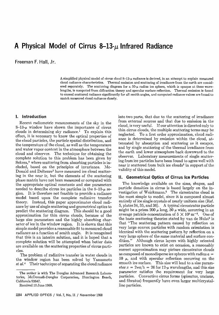
On 7 January 1966 there was a total of 1.33 cm pre-cipitable water, meteorological range was greater than50 km, and the sky was overcast with cirrostratus andcirrus fibratus. The measured data in Fig. 7 exceed
2.4
2.2
2.0
I-
U)
2
C-
2
in
2
UZ
a-IC
.VC
C~
C,
ZENITH ANGLE, DEGREES
Fig. 5. Infrared radiance of a cirrus haze at 8-13.5 u.
transmittance values obtained from the window radia-tion chart,' or
N = N + t(N 5 + N.). (11)
It is seen from Fig. 4, the cloud model, that scatteringalone accounts for less than 0.2 mW cm-' sr-' in thezenith, increasing to three or four times this amount forlarge zenith angles. The thermal emission is greaterthan 0.8 mW cm-' sr-'. Thermal emission was also
1.8
1.6
1.4
1.2
1.0
.8
.6
.4
.2
00 20 40 60 80
ZENITH ANGLE, DEGREES
Fig. 6. Comparison of haze model radiance with measurements.
November 1968 / Vol. 7, No. 11 / APPLIED OPTICS 2267
IU)In
2
2Cl:
vZ
z
C
I
3C)
al,
2
00 20 40 60 80
ZENITH ANGLE, DEGREES
Fig. 7. Comparison of cloud model radiance with measurements.
that for the cirrus cloud model, represented by thedashed line, but clearly the cloud model gives a better fitthan the emission due to the precipitable water alone.To explain the large sky radiance values measured, itmust be assumed that the cloud was considerablywarmer than 2380K, and that the clouds may have beenthicker than the 200-m layer assumed.
VI. Polarization EffectsAnother characteristic of cirrus scattered radiation
may be predicted from the intensity functions in Fig. 2,and the cirrus cloud model scattering curve in Fig. 4.It will be noted that significant polarization is predictedby the intensity functions for scattering angles between40' and 1200. It is therefore not unexpected that thepolarization measurements of cirrus described in anearlier paper' showed positive polarization where thedegree of polarization is defined by
P = (i, - i2)/(i, + i2) = (i. - i/(i± + ill). (12)
Here a vertical plane serves as the reference; radiationwith the electric vector in this plane is defined as havingparallel polarization.
To compute the expected degree of polarization byuse of the reflectance functions of Fig. 2, the earth'ssurface was taken to be a flat plane subtending 2 7r srbelow the cirrus scattering center. This plane wasdivided into a number of areas, each subtending anequal solid angle from the scattering center. In theabsence of atmospheric attenuation, the radiance fromeach lambertian area will lead to equal irradiancevalues at the cirrus, and the polarization measured bythe observer at zenith angle r will then be
PW= [7 (i) - > (i 2 )j/[ (i,)j + 7 (i2)j] (13)
where the individual intensities defined by the scatter-ing angle 0 are given by
il,2 = i(O),2 COs'# + i(0)2,1 sin2#, (14)
with A1 being the intersection angle of the scattering planeand the vertical observation plane. Equation (13) wasevaluated for = = 60° where maximum polarization wasfound and j = 61. With no atmospheric attenuation,and i(0)1,2 given by Fig. 2, a value of P60o = 0.10 was ob-tained. The calculation showed that while scatteredirradiance from areas close to the nadir contributedpositive polarization, this polarization value was re-duced by the negative polarization of scattered irradi-ance from zones near the horizon. Therefore, when anattenuating atmosphere was considered, emitting at alower temperature than the earth's surface, the cirrusscattered radiance polarization became more positive.Taking typical clear winter day transmittance for thedifferent zenith angles, a value of P60o = 0.12 was com-puted.
Only a fraction of the sky radiance is due to scatteringin the cirrus, however. Thermal emission from thecloud and tropospheric water vapor should be un-polarized. Referring to Fig. 4, it is seen that about13% of the sky radiance at v = 600 is due to scattering.Thus, the expected cirrus polarization should be posi-tive, and of the order 0.02, whereas a maximum value of0.04 was measured.
VII. ConclusionsA simplified model for predicting the thermal emis-
sion and scattering from thin cirrus clouds has been de-rived. The model predicts cloud radiance which isfound to agree rather closely with measured radiancevalues in the S-13.5-g window. On days with a thincirrus haze, the model nearly matches to within experi-mental error the measured radiance distributions tozenith angles as large as 600. On days with an easilyvisible cirrus overcast, emission and scattering as pre-dicted by the model matched the measured data moreclosely than did a radiation chart prediction. It is con-cluded that the emission and scattering from cirrusclouds can account for measured values of radiancemore accurately than can emission due only to strongwater vapor line wings in the window, except when thesky is visually clear with little evidence of an ice hazeproduced solar aureole.
Since cirrus ice particles are such efficient radiators inthe ir, because of their absorbing properties and largesize, they can significantly cool the air in which they areimbedded. Warmer air underlying a radiatively cooledcirrus layer may lead to an unstable lapse rate, and toconvective stirring and turbulence. This may explain arecent observation 4 that many cases of clear air tur-bulence are associated with cirrostratus clouds.
References1. F. F. Hall, Jr., Appl. Opt. 7, 891 (1968).2. Z. Sekera, "Radiative Transfer in a Planetary Atmosphere
with Imperfect Scattering," Rand Corp. R-413-PR, June1963 (AD 407 493).
2268 APPLIED OPTICS / Vol. 7, No. 11 / November 1968
3. R. K. McDonald and R. W. Deltenre, J. Opt. Soc. Amer. 53, 9. S. Twomey, Tables of Scattering and Extinction Efficiencies,860 (1963). unpublished computations by U. S. Weather Bureau, Wash-
4. G. Yamamoto, M. Tanaka, and K. Kamitani, J. Atmos. ington, D. C. (1963).Sci. 23,305 (1966). 10. Ref. 6, p. 99.
5. H. Weickmann, Ber. Deut. Wetter. U. S. Zone 6, 61 (1949) 11. J. R. Hodkinson, in Electromagnetic Scattering, M. Kerker,(available from NASA as R&T 273). Ed. (Pergamon Press, Inc., New York, 1963), pp. 87-100.
6. H. C. van de Hulst, Light Scattering by Small Particles (John 12. F. F. Hall, Jr., Appl. Opt. 3, 781 (1964).Wiley & Sons, Inc., New York, 1957), p. 1 11.13 R.0GupehanC.MSlpevcJPysCem57
7. W. M. Irvine and J. B. Pollack, Icarus 8, 324 (1968). 13. R. 0. Gumprecht and C. . Sliepcevich, J. Phys. Chem. 57,8. D. Deirmendjian, R. Clasen, and W. Viezee, J. Opt. Soc. 90 (1953).
Amer. 51, 620 (1961). 14. P. J. Klass, Aviation Week & Space Technol. 88, 80 (1968).
Volume 58, No. 9 JOURNAL OF THE OPTICAL SOCIETY OF AMERICA September 1968
Optical Waveguides Formed by Proton Irradiation of Fused Silica . .. . . . . . . . . . . . . . . . . . . . . . . .E. Ronald Schineller, Richard P. Flam, and Donald W. Wilmot 1171
Coherent Interactions between Optical Waveguides and Lasers. . N. S. Kapany, J. J. Burke, K. L. Frame, and R. E. Wilcox 1176Grating Anomalies as a Local Phenomenon . . . . . . . . . . . . . . . C. Harvey Palmer and Frederick W. Phelps, Jr. 1184Reflection Efficiencies of Grating in the Soft X-Ray Region . . . . . . . . . . . . . Shiro Fujiwara and Yasuo Iguchi 1189Excitation of K-Shell Electrons in Be by Soft X Rays and 20-keV Electrons . . . . . . . . .N. Swanson and K. Codling 1192Present State of Analysis of the First Spectrum of Thorium (Th I) . . . . . . . . . . . . . . . . . . Romuald Zalubas 1195Transition Probabilities in the Spectra of Ne I, Ar I, and Kr I . . . . . . . . . . . . . . . . . . . . Peter W. Murphy 1200Electronic Raman Spectra. IV: Relation between the Scattering Tensor and the Symmetry of the Crystal Field .
.. ........ ........... ........ . . . . .J. A. Koningstein and 0. Sonnich Mortensen 1208Random Band Models with Lines of Pure Doppler Shape. .. . . . . . . . . . . . . . . . . . . . W. Malkmus 1214Polymeric Matrices for Organic Phosphors . . . . . . . . . . . . Nicholas Geacintov, Gerald Oster, and Thomas Cassen 1217Influence of Impurities on the Optical Absorption Edge of Gallium Arsenide from 2970 to 40K . . .
. . . . . . . . . . . . . . . .Jacques Lefevre, Daniel Bois, Pierre Pinard, Francois Davoine, and Pierre Leclerc 1230New Approach to the Phase Problem in Optical Theory. . . .. . . . . . . . . . . . . . . . . . . C. L. Mehta 1233Conditions for the Validity of the Angular Spectrum of Plane Waves. .. . . . . . . . . . . . . . . .Eamon Lalor 1235Coherence Properties of Optical Fields. II. Study of Experiments Described by Fourth-Order Coherence Functions .
. . . . . . . . . . . . . . . . . . . . . . . . . . . . . . . . . . . . . . . . .. E. Boileau and B. Picinbono 1238Determination of the Modulation Transfer Function of Photographic Emulsions from Physical Measurements
.. ..... ..... ... .. ....... ...... . R. N. Wolfe, E. W. Marchand and J. J. DePalma 1245Radiometry and Coherence. . . . . . . . . . . . . . . . . . . . . . . . . . . . . . . . . . A. Walther 1256Rayleigh Scattering of Ruby-Laser Light by Neutral Gases . . . . . . . . . . . Ralph R. Rudder and David R. Bach 1260Permanence of the Log-Normal Distribution. .. . . . . . . . . . . . . . . . . . . . . . . . .R. L. Mitchell 1267Optimum, Nonlinear Processing of Noisy Images. .. . . . . . . . . . . . . . . . . . . . . . . . B. Roy Frieden 1272Effects of Film Nonlinearities on Wavefront-Reconstruction Images of Diffuse Objects . . J. W. Goodman and G. R. Knight 1276Three-Dimensional Fourier-Transforn Method for Synthesizing Binary Holograms . . . . . . . . . . . .James P. Waters 1284Comparison of Experimental and Theoretical Holographic Image Radiance. .F. G. Kaspar, R. L. Lamberts, and C. D. Edgett 1289Standard Observer for Large-Field Photometry at Any Level. .. . . . . . . . . . . . . . . . . . .D. A. Palmer 1296Perturbation Approach to Spatial Brightness Interaction in Human Vision . . . . . . . . . . . . . . Michael Davidson 1300Letters to the Editor:
Influence of Geometry and Light of High Luminance on Glare Impression . . . . . . . . . .Roger L. Saur and Slavko M. Dobrash 1309Elimination of Polarization Corrections from Optical Excitation-Function Measurements. . John W. Woolsey and John W. McConkey 1309Brightness of Ramp Stimuli as a Function of Plateau and Gradient Widths . . . . . . . . Donald C. Hood and John A. Whiteside 1310Overlapping Atomic Multiplets . . . . . . . . . . . . . . . . . . . . . . . . . . . . . . . . B. R. Judd 1311Origin of Dark Noise in Human Foveal Vision. . . . . . . . . . . . . . . . . . . . . . . . . Richard Srebro and Allan Jaffe 1313Zeeman Effect in a Spinless Two-Body System .. ... . . . . . . . . . . . Ernst Breitenberger 1315Spectral Lines for Refractometry . . . . . . . . . . . . . . . . . . . . . . . . . . . . . . . . . .Habell and A. Jackson 1316
Book Reviews:The Swan System of the C2 Molecule; The Spectrum of the HgH Molecule. By John G. Phillips and Summer P. Davis .... . . . 1316Oscillator Strengths and Transition Probabilities for 3288 Lines of Fe I. By C. H. Corliss and I. L. Tech . . . . . . . . . . 1317Advances in Microwaves. Vol. 1. Edited by Leo Young .. Reviewed by Walter K. Kahn 1317Advances in Microwaves. Vol. 2. Edited by Leo Young . . . . . . . . . . . . . . . . . . . . .Reviewed by James E. Burke 1317Dynamical Processes in Solid State Optics. Edited by R. Kubo and H. Kamimula . . . . . . . .Reviewed by Benjamin B. Snavely 1319Electro-Optical Photography at Low Illumination. By Harold V. Soule . .. . . . . . . . . . . . Reviewed by James E. LuValle 1319Progress in Optics. Volume VI. Edited by E. Wolf .. . . . . ...... . .. Reviewed by P. B. Mauer 1320
Announcements .......... . ... . ... . 1320Contents:
Optik, Band 27, Heft 3, 4 . ................... .. 1321
Personalia:Adriaan Walther .1321
Necrology:William W. Woodbury .1321Alexander Boyd McLay .1321
OSA Technical Groups . . . . . . . . . . . . . . . . . . . . . . . . . . . . . 1 . . . . . . . . . . . . . . . . 1322Technical Calendar ..... . . . . . . . . . . . . . . . . . . . . . . . . . . . . . . . . . . . . . . . . . . 1322From the Executive Office . . . . .1.3.2.3.................. . ... .. .. . . . . . . . ... 1323Editor's Page . . . . . . . . . . . . . . . . . . . . . . . . . . . . . . . . . . . . . . . . . . . . . . . . . . 1324
November 1968 / Vol. 7, No. 11 / APPLIED OPTICS 2269