a model-driven approach to support engineering changes … · a model-driven approach to support...
TRANSCRIPT
R.B. France et al. (Eds.): MODELS 2012, LNCS 7590, pp. 368–382, 2012. © Springer-Verlag Berlin Heidelberg 2012
A Model-Driven Approach to Support Engineering Changes in Industrial Robotics Software
Yu Sun1, Jeff Gray2, Karlheinz Bulheller3, and Nicolaus von Baillou3
1 University of Alabama at Birmingham, Birmingham AL 35294 [email protected]
2 University of Alabama, Tuscaloosa, AL 35401 [email protected]
3 Bulheller Consulting, Inc., Tuscaloosa, AL 35406 bulheller+partner ingenieure, Boeblingen, Germany
{k.bulheller,n.vonbaillou}@bulheller-consulting.com
Abstract. Software development has improved greatly over the past decades with the introduction of new programming languages and tools. However, software development in the context of industrial robotics is dominated by practices that require attention to low-level accidental complexities related to the solution space of a particular domain. Most vendor-specific robotics platforms force the developer to be concerned with many low-level implementation details, which presents a maintenance challenge in the context of making engineering changes to the robotics solution. Additionally, satisfying the timing requirements across the platforms of multiple robot vendors represents an additional challenge. We introduce our work using Domain-Specific Modeling to support the control of industrial robots using models that are at a higher level of abstraction than traditional robot programming languages. Our modeling approach assists robotics developers to plan the schedule, validate timing requirements, optimize robot control, handle engineering changes, and support multiple platforms.
Keywords: Domain-Specific Modeling, Robotics, Software Maintenance, Digital Factory, Digital Master.
1 Challenges in Industrial Robotics
Industrial robots have been applied widely in various domains to perform different tasks [4][9], such as welding robots used in the automobile industry, or assembly robots used in manufacturing factories. Robots are often controlled and programmed using textual and imperative robot programming languages that are customized environments from each robot vendor. Even with the implementation of a digital factory (i.e., a virtual representation of the manufacturing process and facility), most robotics languages are domain-specific languages designed by specific robot vendors (e.g., the KUKA [14] robot programming language, and RAPID [16] from ABB [15]), they are still at a low-level of abstraction. This requires a great deal of knowledge
A Model-Driven Approach to Support Engineering Changes 369
about implementation and configuration details (e.g., the coordinates of the movement destination, the speed and acceleration of the movement, the ports to write and read data), which presents a host of challenges in robotics software development and maintenance. Based on our 20+ years of automotive industry experience, the following paragraphs describe what we have observed as the key challenges in supporting engineering changes in industrial robotics software (in particular, in an automotive factory context using digital factory methodologies).
Challenge 1 – The Complexity of Adapting Engineering Changes Across Robotics Software Solutions. Similar to other types of software development, software evolution is also inevitable in robotics development. For instance, working on different types of products and work tasks, robots need to be modified frequently with different hardware parameters, environment configurations, and more importantly a different sequence of actions needed to address a new requirement on the assembly line. Changing and evolving the robot programs to adapt to new requirements is challenging, particularly when performing the changes on large-scale heterogeneous robotics systems. To make an engineering change across a specific cell of an assembly line, robotics programmers need to search through a collection of robot programs manually, locate the correct location of low-level configuration information, and make the correct modification corresponding to the new requirement.
Challenge 2 – The Difficulty of Satisfying Timing Requirements and Optimizing Action Schedules for Cycle Time Optimization. The correct timing and scheduling configuration on a robotics system plays an essential role in multi-robot coordination. Consider the category of welding robots as an example, where each robot must finish its own task on time and ensure the robot next to it has the needed parts within a certain time target. Failure to meet a task deadline in the prescribed time will either cause unnecessary delays or trigger collision conflicts among different robots. In order to minimize the duration of completing a certain task, an optimized schedule for each robot is required to avoid unnecessary delays. However, due to a lack of native support for time in most robot programming languages, satisfying the correct timing requirements in robotics development has become a tedious, time-consuming and error-prone task that requires much manual tweaking and refined intuition in order to elaborate a successful implementation. The most commonly used approach in practice is to plan the schedule manually, and then hand it to robot developers who then implement the schedule plan manually. There are several current well-known automotive factories that still use standard spreadsheets for determining such timing considerations. Developers must write robot programs based on the timing requirements, and test the program in an ad hoc manner to obtain various timing measurements during commissioning. If the measurement indicates the violation of specific timing requirements, changes must be made either to the schedule or the robot programs. This process iterates until all the timing requirements are satisfied. This type of scenario, based on manual and iterative refinements, is ripe for application of model-driven techniques.
Challenge 3 – The Challenge of Supporting Multiple Platforms. With multiple robot manufactures throughout a manufacturing facility, it is often necessary to swap

370 Y. Sun et al.
out robots from different vendors at different stations in a manufacturing cell. However, if each vendor uses a different robot programming language, the same task will have to be programmed multiple times in different languages. This requires much redundancy and maintenance of multiple programs for the same task – a situation that is fertile for creating software failures. A desired capability is to be able to describe the intellectual property associated with a robot task at a level that can be maintained and preserved across current vendors. Such a capability would also protect against obsolescence and allow integration of future robot platforms that may later emerge.
We have designed a modeling, planning, and code generation tool suite that addresses the needs of these three challenges. This tool, called Automax, serves as the future input to our existing robotics optimization solution (called Robmax) that is currently deployed on over 3,000 industrial robots in “Body in White”1 shops at manufacturing facilities in the USA and Europe. The main objectives of our work described in this paper are: 1) to raise the level of abstraction in robotics programming and hide the low-level implementation details. This is done by capturing key domain concepts and constructing code frameworks and libraries, in order to facilitate multiple types of engineering changes on the manufacturing line; 2) to combine timing and scheduling information for robot programs, and provide timing analysis to ease the process of satisfying timing requirements; 3) to build a common representation for expressing robot control, from which automatic generation to specific vendor platforms is possible.
An overview of the proposed solution will be given in Section 2, followed by the illustration of each key component in the solution from Section 3 to Section 5. Section 6 summarizes the related work and Section 7 offers concluding remarks.
2 Automax Overview
Our solution to address the key challenges presented in Section 1 is to use Domain-Specific Modeling (DSM) [3] to support robotics development. Raising the level of abstraction from programming languages to modeling languages has been shown to be an effective approach to attack the increasing complexity of software systems [1]. Domain-Specific Modeling Languages (DSMLs) [2] assist domain experts in focusing on the level of abstraction relevant to their problem space by providing notations and constructs tailored specifically to that domain, while removing the accidental concerns of a specific solution space. DSMLs help to represent the solution of the problem domain and reduce miscommunication between stakeholders by providing common abstractions and notations.
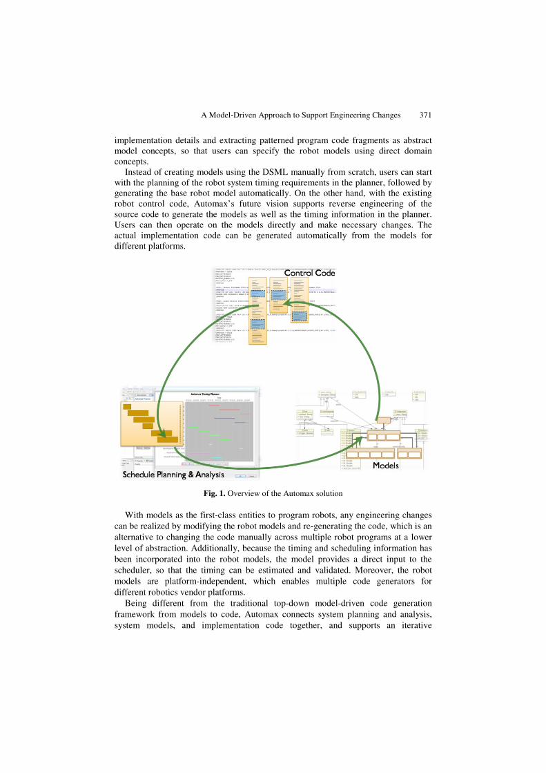
Figure 1 is an overview of our solution. The core part of the solution is a graphical DSML defined by a metamodel specifically for the industrial robotics domain. Our modeling language captures the key configurations for robots, all types of actions an industrial automotive manufacturing robot can perform, as well as the scheduling and timing information. Compared with traditional robot programming languages (e.g., KUKA), this DSML is at a higher level of abstraction by hiding many low-level 1 Body In White refers to a phase of automotive manufacturing when the metal body of the car
has been welded together, just before the addition of attached structures (e.g., doors) and prior to painting.
A Model-Driven Approach to Support Engineering Changes 371
implementation details and extracting patterned program code fragments as abstract model concepts, so that users can specify the robot models using direct domain concepts.
Instead of creating models using the DSML manually from scratch, users can start with the planning of the robot system timing requirements in the planner, followed by generating the base robot model automatically. On the other hand, with the existing robot control code, Automax’s future vision supports reverse engineering of the source code to generate the models as well as the timing information in the planner. Users can then operate on the models directly and make necessary changes. The actual implementation code can be generated automatically from the models for different platforms.
Fig. 1. Overview of the Automax solution
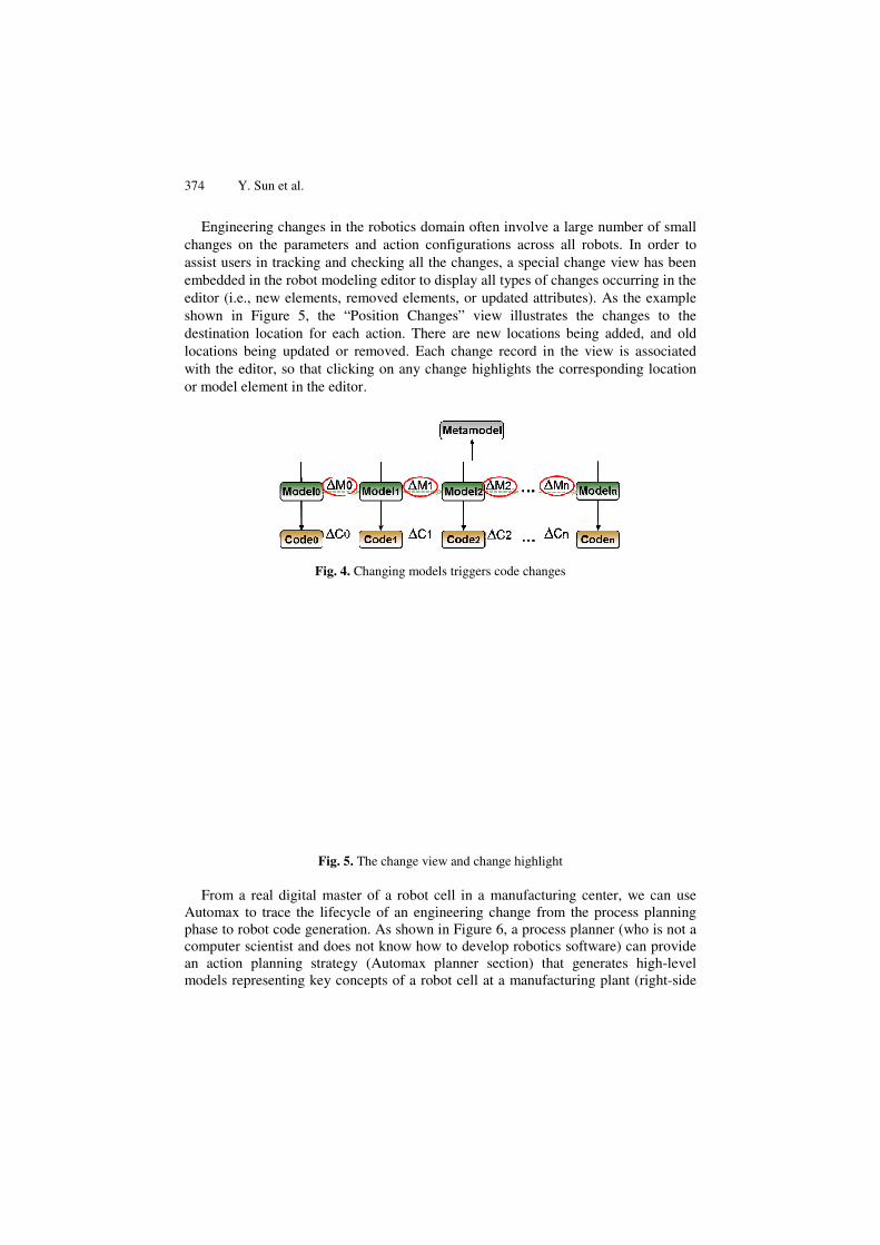
With models as the first-class entities to program robots, any engineering changes can be realized by modifying the robot models and re-generating the code, which is an alternative to changing the code manually across multiple robot programs at a lower level of abstraction. Additionally, because the timing and scheduling information has been incorporated into the robot models, the model provides a direct input to the scheduler, so that the timing can be estimated and validated. Moreover, the robot models are platform-independent, which enables multiple code generators for different robotics vendor platforms.
Being different from the traditional top-down model-driven code generation framework from models to code, Automax connects system planning and analysis, system models, and implementation code together, and supports an iterative
372 Y. Sun et al.
development process from planning to models, models to code, and code back to analysis and planning. The goal is to enable users to create models rapidly with integrated timing requirements, directly generate implementation code and measure the performance, and more seamlessly make engineering changes on models and re-generate code.
Our solution with Automax has been implemented as a modeling tool in Eclipse using multiple Eclipse Modeling Projects [17], which provides a unified set of modeling frameworks, tooling, and standards implementations on the evolution and promotion of model-driven development technologies within the Eclipse community. Automax provides a schedule planner, robot modeling editor, code generator, and a number of tools to facilitate the timing and scheduling design, validation, and optimization. The next sections will present the main components of our Automax solution.
3 Using Models to Facilitate Engineering Changes
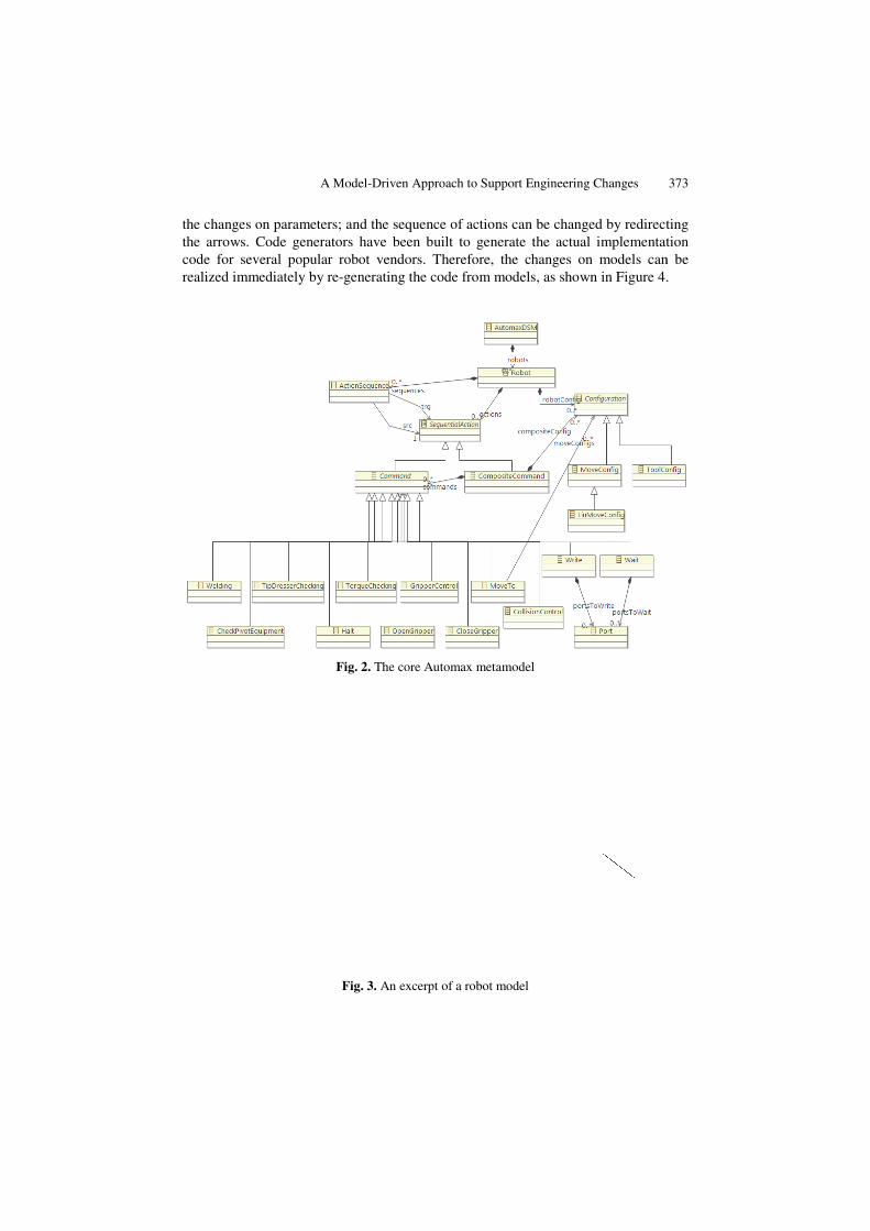
The engineering changes in robotics may emerge from the need for a new group of robots to collaborate with each other, a new sequence of actions to perform, or a new set of configuration parameters for each robot. The main challenge of handling these changes comes from locating the correct parts of the source code and making the needed changes. To raise the level of abstraction, we analyzed the source code of existing robot programs currently in use within an automotive assembly line and identified the key concepts and relationships in the robotics domain through a manual reverse-engineering process (i.e., identify the functions or statement blocks in the source code and extract them as unique and reusable modeling concepts). A DSML was defined using these concepts. Figure 2 shows the core part of the metamodel used to define the Automax DSML, with the model attributes and some extra data types elided. A robotics configuration can include multiple robots. Each robot can perform various types of sequential actions, such as moving, welding, opening/closing grippers, checking pivot equipment and halting. Corresponding attributes are available for direct configuration for each action. The Composite command pattern can be used to include a group of actions. Special configurations (e.g., movement configuration, tooling configuration) are available for separate definition and shared by the action commands. Advanced flow control mechanisms such as repetition and decision-making are not defined in the metamodel for the purpose of hiding the low-level programming details.
Figure 3 shows an excerpt of a robot model instance. Users can construct a group of robots, configure the actions and parameters in the editor, and specify the sequence of actions using arrows. Based on this DSML, any engineering changes defined in the Digital Master of the product can be implemented by modifying the model instances to adopt the changes in the manufacturing process. For example, a group of robots can be changed by directly adding or removing robots; the actions for each robot can be updated by editing the action command model elements; the attribute editor allows
A M
the changes on parameters; the arrows. Code generatocode for several popular rrealized immediately by re-
F
F
Model-Driven Approach to Support Engineering Changes
and the sequence of actions can be changed by redirectrs have been built to generate the actual implementat
robot vendors. Therefore, the changes on models can-generating the code from models, as shown in Figure 4.
Fig. 2. The core Automax metamodel
Fig. 3. An excerpt of a robot model
373
ting tion
n be .
374 Y. Sun et al.
Engineering changes in tchanges on the parametersassist users in tracking andembedded in the robot modeditor (i.e., new elements, shown in Figure 5, the “destination location for eaclocations being updated orwith the editor, so that clicor model element in the edi
Fig. 4
Fig. 5
From a real digital masAutomax to trace the lifecphase to robot code generatcomputer scientist and doesan action planning strategmodels representing key co
the robotics domain often involve a large number of sms and action configurations across all robots. In order
d checking all the changes, a special change view has bdeling editor to display all types of changes occurring in removed elements, or updated attributes). As the exam“Position Changes” view illustrates the changes to ch action. There are new locations being added, and r removed. Each change record in the view is associacking on any change highlights the corresponding locatitor.
4. Changing models triggers code changes
5. The change view and change highlight
ter of a robot cell in a manufacturing center, we can ycle of an engineering change from the process planntion. As shown in Figure 6, a process planner (who is nos not know how to develop robotics software) can provgy (Automax planner section) that generates high-leoncepts of a robot cell at a manufacturing plant (right-s
mall r to
been the
mple the old
ated tion
use ning ot a vide evel side

A Model-Driven Approach to Support Engineering Changes 375
of Figure 6, where the Palette represents the visualized domain concepts available from the Automax metamodel definition). From this model, robot code can be generated within seconds, from what previously would take several weeks. From our experience, this new capability allows the exploration of the design alternatives in a way that is very productive (within seconds) and accurate (the maturity of the code generators produces code that is always more reliable than human-generated code), allowing engineers the flexibility to understand design tradeoffs in a manner that is currently not possible due to the time needed for manual adaptation.
Fig. 6. The integration of planning and high-level robot control in Automax
The basic implementation of this tool is based on the Eclipse Modeling environment. The metamodel is defined using EMF [13][18] and the editing environment is generated using GMF [19]. Building and maintaining a modeling tool with GMF is not an easy task, which requires six individual models that are highly dependent on each other and all need to be in sync with each other. Instead of creating these models manually one by one, we use the Eugenia tool [20], which considerably sped up the creation of the graphical DSML editors. The Eugenia tool essentially reduces development and maintenance effort down to one model plus some optional, separate customization information.
4 Incorporating Timing Requirements to Optimize Schedules
The separation of timing and scheduling information from the traditional robot control programs in process planning makes it difficult to satisfy and validate timing requirements. The traditional robotics development requires a timing plan on paper
376 Y. Sun et al.
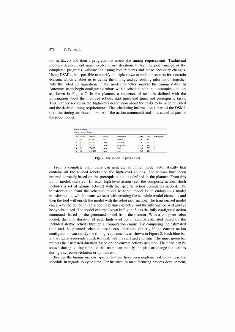
(or in Excel) and then a program that meets the timing requirements. Traditional robotics development may involve many iterations to test the performance of the completed programs, validate the timing requirements and make necessary changes. Using DSMLs, it is possible to specify multiple views or multiple aspects for a certain domain, which enables us to define the timing and scheduling information together with the robot configurations in the model to better analyze the timing status. In Automax, users begin configuring robots with a schedule plan in a customized editor, as shown in Figure 7. In the planner, a sequence of tasks is defined with the information about the involved robots, start time, end time, and prerequisite tasks. This planner serves as the high-level description about the tasks to be accomplished and the desired timing requirements. The scheduling information is part of the DSML (i.e., the timing attributes in some of the action command) and thus saved as part of the robot model.
Fig. 7. The schedule plan editor
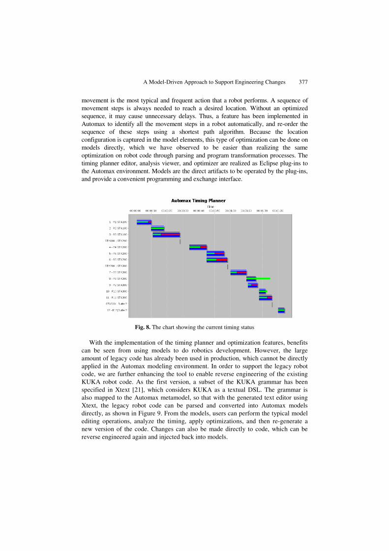
From a complete plan, users can generate an initial model automatically that contains all the needed robots and the high-level actions. The actions have been ordered correctly based on the prerequisite actions defined in the planner. From this initial model, users can fill each high-level action (i.e., the composite action which includes a set of atomic actions) with the specific action commands needed. The transformation from the schedule model to robot model is an endogenous model transformation, which means we start with creating the schedule model elements, and then the tool will enrich the model with the robot information. The transformed model can always be edited in the schedule planner directly, and the information will always be synchronized. The model excerpt shown in Figure 3 has the fully configured action commands based on the generated model from the planner. With a complete robot model, the total duration of each high-level action can be estimated based on the included atomic actions through a computation engine. By comparing the estimated time and the planned schedule, users can determine directly if the current action configuration can satisfy the timing requirements, as shown in Figure 8. Each blue bar in the figure represents a task to finish with its start and end time. The inner green bar reflects the estimated duration based on the current actions included. The chart can be shown during editing time, so that users can modify the plan or change the actions during a schedule violation or optimization.
Besides the timing analysis, special features have been implemented to optimize the schedule in regards to cycle time. For instance, in manufacturing process development,
A Model-Driven Approach to Support Engineering Changes 377
movement is the most typical and frequent action that a robot performs. A sequence of movement steps is always needed to reach a desired location. Without an optimized sequence, it may cause unnecessary delays. Thus, a feature has been implemented in Automax to identify all the movement steps in a robot automatically, and re-order the sequence of these steps using a shortest path algorithm. Because the location configuration is captured in the model elements, this type of optimization can be done on models directly, which we have observed to be easier than realizing the same optimization on robot code through parsing and program transformation processes. The timing planner editor, analysis viewer, and optimizer are realized as Eclipse plug-ins to the Automax environment. Models are the direct artifacts to be operated by the plug-ins, and provide a convenient programming and exchange interface.
Fig. 8. The chart showing the current timing status
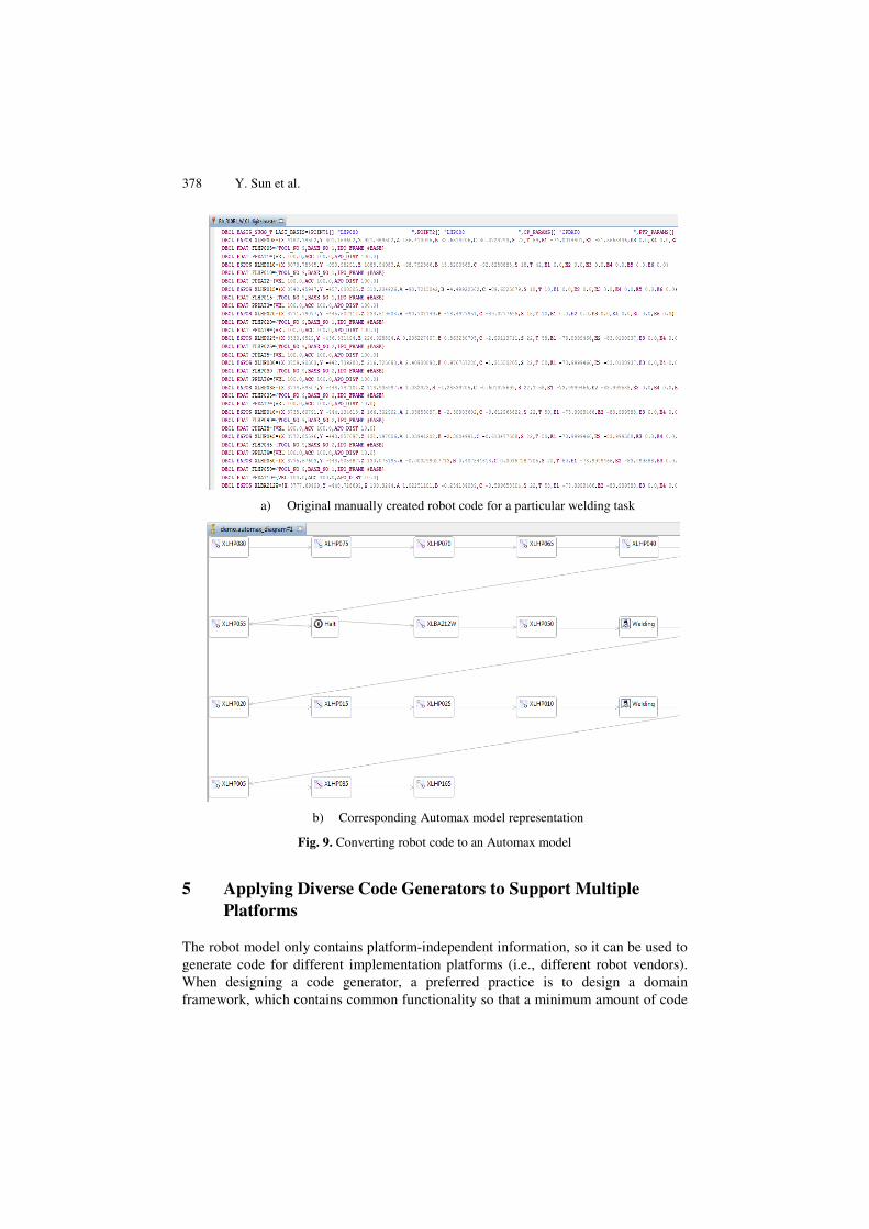
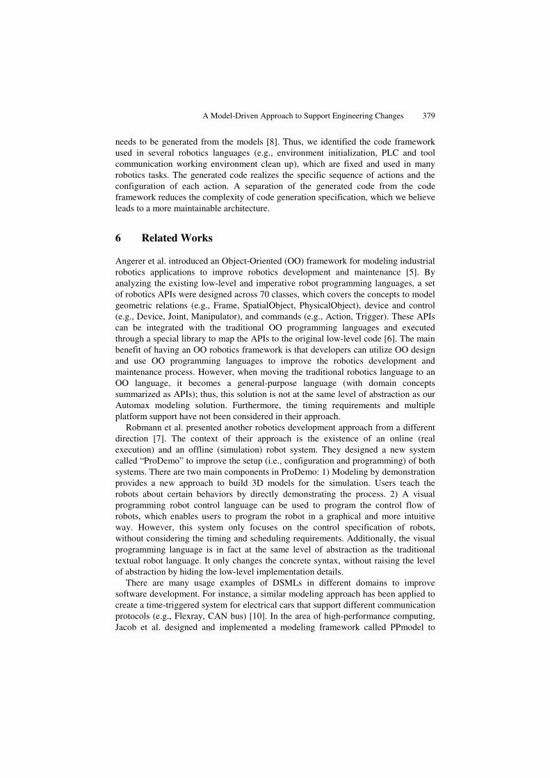
With the implementation of the timing planner and optimization features, benefits can be seen from using models to do robotics development. However, the large amount of legacy code has already been used in production, which cannot be directly applied in the Automax modeling environment. In order to support the legacy robot code, we are further enhancing the tool to enable reverse engineering of the existing KUKA robot code. As the first version, a subset of the KUKA grammar has been specified in Xtext [21], which considers KUKA as a textual DSL. The grammar is also mapped to the Automax metamodel, so that with the generated text editor using Xtext, the legacy robot code can be parsed and converted into Automax models directly, as shown in Figure 9. From the models, users can perform the typical model editing operations, analyze the timing, apply optimizations, and then re-generate a new version of the code. Changes can also be made directly to code, which can be reverse engineered again and injected back into models.
378 Y. Sun et al.
a) Original manually created robot code for a particular welding task
b) Corresponding Automax model representation
Fig. 9. Converting robot code to an Automax model
5 Applying Diverse Code Generators to Support Multiple Platforms
The robot model only contains platform-independent information, so it can be used to generate code for different implementation platforms (i.e., different robot vendors). When designing a code generator, a preferred practice is to design a domain framework, which contains common functionality so that a minimum amount of code
A Model-Driven Approach to Support Engineering Changes 379
needs to be generated from the models [8]. Thus, we identified the code framework used in several robotics languages (e.g., environment initialization, PLC and tool communication working environment clean up), which are fixed and used in many robotics tasks. The generated code realizes the specific sequence of actions and the configuration of each action. A separation of the generated code from the code framework reduces the complexity of code generation specification, which we believe leads to a more maintainable architecture.
6 Related Works
Angerer et al. introduced an Object-Oriented (OO) framework for modeling industrial robotics applications to improve robotics development and maintenance [5]. By analyzing the existing low-level and imperative robot programming languages, a set of robotics APIs were designed across 70 classes, which covers the concepts to model geometric relations (e.g., Frame, SpatialObject, PhysicalObject), device and control (e.g., Device, Joint, Manipulator), and commands (e.g., Action, Trigger). These APIs can be integrated with the traditional OO programming languages and executed through a special library to map the APIs to the original low-level code [6]. The main benefit of having an OO robotics framework is that developers can utilize OO design and use OO programming languages to improve the robotics development and maintenance process. However, when moving the traditional robotics language to an OO language, it becomes a general-purpose language (with domain concepts summarized as APIs); thus, this solution is not at the same level of abstraction as our Automax modeling solution. Furthermore, the timing requirements and multiple platform support have not been considered in their approach.
Robmann et al. presented another robotics development approach from a different direction [7]. The context of their approach is the existence of an online (real execution) and an offline (simulation) robot system. They designed a new system called “ProDemo” to improve the setup (i.e., configuration and programming) of both systems. There are two main components in ProDemo: 1) Modeling by demonstration provides a new approach to build 3D models for the simulation. Users teach the robots about certain behaviors by directly demonstrating the process. 2) A visual programming robot control language can be used to program the control flow of robots, which enables users to program the robot in a graphical and more intuitive way. However, this system only focuses on the control specification of robots, without considering the timing and scheduling requirements. Additionally, the visual programming language is in fact at the same level of abstraction as the traditional textual robot language. It only changes the concrete syntax, without raising the level of abstraction by hiding the low-level implementation details.
There are many usage examples of DSMLs in different domains to improve software development. For instance, a similar modeling approach has been applied to create a time-triggered system for electrical cars that support different communication protocols (e.g., Flexray, CAN bus) [10]. In the area of high-performance computing, Jacob et al. designed and implemented a modeling framework called PPmodel to
380 Y. Sun et al.
assist programmers in separating the core computation from the details of a specific parallel architecture, identifying and retargeting the parallel section of a program to execute in a different platform [11]. Another example is the application of model-driven engineering and a supporting tool infrastructure for the industrial process control domain, done by Lukman et al. [12]. The work described in this paper distinguishes itself from the following aspects: 1) it focuses on the robotics domain; 2) non-functional requirements (i.e., timing and scheduling requirements) have been integrated with domain concepts and reflected in the generated code; 3) performance analysis and optimization can be made to models during editing time; 4) the same metamodel is mapped to both the textual and the graphical DSL so that the two formats can be interchanged with each other; 5) an iterative development approach and reverse engineering are both supported in our framework.
7 Conclusions and Future Work
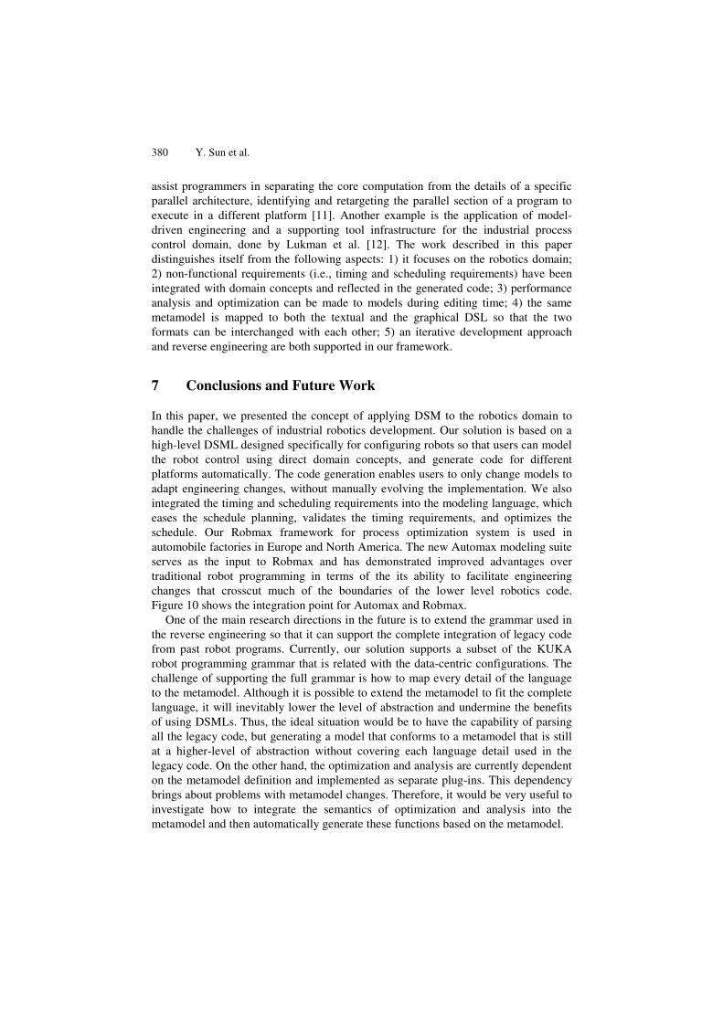
In this paper, we presented the concept of applying DSM to the robotics domain to handle the challenges of industrial robotics development. Our solution is based on a high-level DSML designed specifically for configuring robots so that users can model the robot control using direct domain concepts, and generate code for different platforms automatically. The code generation enables users to only change models to adapt engineering changes, without manually evolving the implementation. We also integrated the timing and scheduling requirements into the modeling language, which eases the schedule planning, validates the timing requirements, and optimizes the schedule. Our Robmax framework for process optimization system is used in automobile factories in Europe and North America. The new Automax modeling suite serves as the input to Robmax and has demonstrated improved advantages over traditional robot programming in terms of the its ability to facilitate engineering changes that crosscut much of the boundaries of the lower level robotics code. Figure 10 shows the integration point for Automax and Robmax.
One of the main research directions in the future is to extend the grammar used in the reverse engineering so that it can support the complete integration of legacy code from past robot programs. Currently, our solution supports a subset of the KUKA robot programming grammar that is related with the data-centric configurations. The challenge of supporting the full grammar is how to map every detail of the language to the metamodel. Although it is possible to extend the metamodel to fit the complete language, it will inevitably lower the level of abstraction and undermine the benefits of using DSMLs. Thus, the ideal situation would be to have the capability of parsing all the legacy code, but generating a model that conforms to a metamodel that is still at a higher-level of abstraction without covering each language detail used in the legacy code. On the other hand, the optimization and analysis are currently dependent on the metamodel definition and implemented as separate plug-ins. This dependency brings about problems with metamodel changes. Therefore, it would be very useful to investigate how to integrate the semantics of optimization and analysis into the metamodel and then automatically generate these functions based on the metamodel.
A Model-Driven Approach to Support Engineering Changes 381
Fig. 10. Automax interaction with Robmax (a highly successful automation efficiency solution already deployed across 3,000 robots in Europe and North America)
Acknowledgement. This work is supported by NSF CAREER award CCF-1052616.
References
1. Schmidt, D.: Model-Driven Engineering. IEEE Computer 39(2), 25–32 (2006) 2. Lédeczi, Á., Bakay, Á., Maróti, M., Völgyesi, P., Nordstrom, G., Sprinkle, J., Karsai, G.:
Composing Domain-Specific Design Environments. IEEE Computer 34(11), 44–51 (2001) 3. Gray, J., Tolvanen, J., Kelly, S., Gokhale, A., Neema, S., Sprinkle, J.: Domain-Specific
Modeling. In: Handbook of Dynamic System Modeling, ch. 7, pp. 7.1–7.20. CRC Press (2007)
4. Brogardh, T.: Present and Future Robot Control Development – An Industrial Perspective. Annual Reviews in Control 31(1), 69–79 (2007)
5. Angerer, A., Hoffmann, A., Schierl, A., Vistein, M., Reif, W.: The Robotics API: An Object-Oriented Framework for Modeling Industrial Robotics Applications. In: IEEE/RSJ International Conference on Intelligent Robots and Systems, Taipei, pp. 4036–4041 (September 2010)
6. Muhe, H., Angerer, A., Hoffmann, A., Reif, W.: On Reverse-engineering the KUKA Robot Language. In: International Workshop on Domain-Specific Languages and Models for Robotic Systems, Taipei, pp. 11–17 (September 2010)
7. Robmann, J., Ruf, H., Schlette, C.: Model-Based Programming “by Demonstration” – Fast Setup of Robot Systems (ProDemo). Advances in Robotics Research 5, 159–168 (2010)
8. Kelly, S., Tolvanen, J.: Domain-Specific Modeling: Enabling Full Code Generation. Wiley (2008)
9. Freund, E., Rossmann, H., Schluse, M., Schlette, C.: Using Supervisory Control Methods for Model Based Control of Multi-agent Systems. In: IEEE Conference on Robotics, Automation and Mechatronics, Singapore, pp. 649–654 (December 2004)
10. Sun, Y., Wienands, C., Felser, M.: Apply Model-Driven Design and Development to Distributed Time-Triggered Systems. In: International Conference on Engineering and Meta-Engineering, Orlando, FL, pp. 557–563 (March 2011)
382 Y. Sun et al.
11. Jacob, F., Gray, J., Bangalore, P., Sun, Y.: A Platform-Independent Tool for Modeling Parallel Programs. In: 49th Annual ACM Southeast Conference, Kennesaw, GA, pp. 138–143 (March 2011)
12. Lukman, T., Godena, G., Gray, J., Strmcnik, S.: Model-Driven Engineering of Industrial Control Process Applications. In: IEEE International Conference on Emerging Technologies and Factory Automation, Bilbao, Spain (September 2010)
13. Budinsky, F., Steinberg, D., Merks, E., Ellersick, R., Grose, T.: Eclipse Modeling Framework. Addison-Wesley (2004)
14. KUKA Robots (2012), http://www.kukarobotics.com/ 15. ABB Group (2012), http://www.abb.com/ 16. RAPID Reference Manual (2012),
http://rab.ict.pwr.wroc.pl/irb1400/overviewrev1.pdf 17. Eclipse Modeling Project, EMP (2012), http://www.eclipse.org/modeling/ 18. Eclipse Modeling Framework, EMF (2012),
http://www.eclipse.org/modeling/emf/ 19. Graphical Modeling Framework, GMF (2012), http://www.eclipse.org/gmf/ 20. Eugenia (2012), http://www.eclipse.org/gmt/epsilon/doc/eugenia/ 21. Xtext (2012), http://www.eclipse.org/Xtext/