a digital simulator design for real-time...
TRANSCRIPT

A DIGITAL SIMULATOR DESIGN FORREAL-TIME AND OPEN-LOOP APPLICATIONS
N.A. Izquierdo Jr.Commonwealth Edison Company
M.Kezunovic, Z.Galijasevic, F.Ji1,A.Gopalakrishnan, J.Domaszewicz
Texas A&M University
U.S.A
Abstract – This paper describes new design of a digital simulatorfor relay testing. The main simulator feature is its capability tooperate in both real-time and open-loop modes. In the real-timemode, the modeling software used is the Real Time System(RTS) developed by Texas A&M University. In the open-loopmode, a standard Electromagnetic Transient Program (EMTP)is used. A common Graphical User Interface (GUI) is used forboth operating modes. The main design features of the simulatorare summarized in this paper.
Keywords – Digital Simulation, Protective Relaying, Relay Testing, EMTP, Real-Time Application
I. INTRODUCTION
Recent development of digital simulator technology hasprovided an opportunity for use of digital simulators in testingprotective relays both in real-time and open-loop modes.Texas A&M University has developed an advanced real-timesimulator under the sponsorship of the Department ofEnergy–Western Area Power Administration (WAPA). Thesimulator was delivered to WAPA in the Spring of 1994, andits real-time operation has been demonstrated [1-3]. Inanother project under EPRI sponsorship, Texas A&MUniversity developed an open-loop simulator aimed at back-to-back testing of two terminal protective relay applications.This design has extensive software capabilities for usersupport in performing relay testing [4]. This simulator hasbeen developed using hardware and software that iscompatible with the ones used in the real-time design. Thisprovides for great flexibility in upgrading from the open-loopdesign to the real-time one [5].1
1The work has been done while the author was with Texas A&M
Recently, Texas A&M University was awarded a contractfrom Commonwealth Edison Company that included thedevelopment of a flexible simulator to operate both in real-time and open-loop modes. Due to the compatibility of theprevious designs, it was possible to provide both modes ofoperation using the same hardware and system softwareenvironment. This paper discusses implementationcharacteristics and major benefits of such a design achievedby providing both operating modes.
II. DESIGN REQUIREMENTS
The simulator was implemented under two sets ofrequirements. One set was related to the general features asfollows:� Simulator hardware should be, as much as possible,
commercially available "off the shelf"� Simulator system software should be standard solution
commercially available "off the shelf"� Simulator application software should be written in high
level programming language and portable� Simulator should have an elaborate Graphical User
Interface implemented using standard X-Windows toolsThe other set of requirements was related to the specific
application constraints as follows:� Simulator should operate in both real-time and open-loop
modes� The real-time mode should allow for interactive testing of
protective relays to change network topology for suchconditions as autoreclosing sequences
� The open-loop mode should allow for interactive testingof protective relays by submitting test files generatedthrough simulations using Electromagnetic TransientProgram (EMTP)
� Graphical User Interface should allow for a commonaccess to both the real-time and open-loop modes [6]
To meet these requirements, a new design had to beimplemented. Various features of both the real-time [3] andopen-loop [7] simulators, previously developed independentlyby Texas A&M University, were combined in one simulatordesign.

III. IMPLEMENTATION
This section describes various implementation aspects ofthe new simulator.
A. System Architecture
The major hardware and software building blocks of thesimulator architecture are shown in Fig. 1.
I/O
DSP
for Three Terminals
GUIRTS
Circuit Breakers
ControllerLAN
XX
RISC RISC
D/A Converters
EMTP + replay
Instrument Transformers
I/O
GUI
Power Amplifiers
Fig. 1. The architecture of the simulator
In the closed-loop operating mode, transient simulation iscarried out on-line so that a real-time change of the networktopology controlled by the relay under test is possible. On theother hand, in the open-loop mode transient simulation isdone off-line so that there is no possibility to change networktopology under the control of the relay. To provide these twomodes, unique hardware and software solutions are used.
The hardware basis of the simulator consists of two RISCcomputers, DSP subsystem, two sets of I/O boards andamplifiers subsystem. One computer serves as a user front-end machine for both open-loop and closed-loop simulators.Graphical user interface software (GUI) runs primarily on thatcomputer. The second computer, the faster one, is dedicatedto run real-time transient simulation as well as real-timereplay of EMTP output file. One set of I/O boards connectsthat computer to the DSP subsystem where the real-timesimulation of instrument transformers and circuit breakerstakes place. Another set of I/O boards serves as a connectionbetween the DSP subsystem and amplifiers' section of thesimulator.
The simulator software consists of the graphical userinterface software, conversion software, software for filemanagement and resource control, as well as real-timesimulation and playback software. Both operating modes ofthe simulator are provided to the user by means of thecommon graphical user interface (GUI). Several programsthat perform conversion between the different file formatsaccompany the user interface software. In the closed-loopmode, network simulation is performed in real-time by the
Real-Time System (RTS) software, while DSP boards-basedsoftware simulates instrument transformers and circuit-breakers. In the open-loop mode, entire network simulation isdone in preparatory phase by EMTP, while only the replay ofthe output file takes place in real-time. File transfer from thegraphical user interface to network simulation software andback is managed by the program called Sequencer. Finally,Controller software is used to ensure that I/O hardware of thesimulator is used on scheduled basis.
B. Hardware Implementation
The simulator hardware is shown in Fig. 2. It can supportup to 3 terminals for relay testing. The system hardwareconsists of two RISC machines, each of which can beequipped with the Graphical User Interface (GUI). However,all connection to the external I/O hardware is made throughthe RISC System/590 only. This is to ensure maximumcomputational speed for the real-time simulation.
The DSP subsystem is composed of a single 'central' DSPand a number of 'peripheral' DSPs (TI's TMS320C40 chips).The central processor is connected to the host and to theperipheral DSPs.
The I/O subsystem is divided into a communicationinterface to receive/send serial data from/to the DSPsubsystem, a D/A subsystem for reconstruction of the analogsignals, a digital I/O subsystem to monitor contact statuschanges of the device under test, and a hardware mechanismfor clock synchronization between the Master and Slave I/Oterminals. Clock Synchronization between the terminals isachieved by using Phase Locked Loop ICs, which ties theSlave Terminal clocks to the Master Terminal clock. The I/Osubsystem and the amplifier subsystem are packaged into acustom designed high-precision cabinet. The interfaces aredesigned so that both open-loop and real-time testings arepossible using the same hardware.
LAN
MICRO
INTERF.6000 590 DSP
I/O
IBM RISC
6000 250IBM RISC
AMPLIFIERS
GUI
SYSTEM
THREE-TERMINAL
RECONSTRUCTION
FILE REPLAY
REAL-TIMESIMULATIONCHANNEL
RELAY
WAVEFORM
Fig. 2. Simulator Hardware

C. Software implementation
The software architecture of the simulator and interactionsbetween its major components are shown in Fig. 3.
EMTP-RTS
EMTP
Conversion
GUI-EMTP
SequencerRTS
EMTP
SoftwareFile Replay
RTS
SoftwareDSP
GUIController
GUI
Sequencer
Conversion
Fig. 3. The software architecture of the simulator
D. Graphical User Interface
The user builds the network in one-line diagram form andinitiates the simulation in both operating modes of thesimulator by using a common graphical user interface. Thenetwork is built in a paint-brush-program way; the userselects with the cursor an icon in the toolbox representing anetwork component, inserts it to the required location in thedrawing area, and connects it to the rest of the network usingediting tools such as move, cut, link, delete, undo, etc. [6].The parameters of the components are entered through amenu-driven interface. Ease of use is further enhanced by theexistence of the libraries of predefined models for some of thecomplex network elements.
As far as the GUI is concerned, there is no differencebetween the two operating modes until the very start of thesimulation. In both modes the same graphical interface isused: the same components and tools are utilized to build thenetwork, and component parameters are defined through thesame menus. The two operating modes are forked byselecting different option provided by the GUI menu beforethe simulation is about to start. This transparency, along withthe unique output file format, is ensured by using theappropriate file conversion prior to the simulation.
In order to support concurrent use of the simulator bymultiple users (in closed-loop and open-loop mode), GUI
software is written as a client program. It means it relies oncertain services provided by the server program (in this casecalled Controller). The service can be either real-timenetwork simulation or real-time waveform file replay.Multiple real-time operations are not allowed at the same timebecause they attempt to use the same hardware, each on theexclusive basis. Therefore, GUI negotiates with theController when to start such an operation.
E. Conversion software
After the user creates a network using one-line networkeditor feature of the GUI, it can be saved in the output file inthe specific format (referred as ".gui"). This file keeps allinformation that enables one to redraw the network at a latertime. However, in order to run the simulation, this file mustbe first converted into another file whose format depends onthe simulation program used in the specific operating mode.
For both possible types of the simulations, ".gui" file needsto be converted into the EMTP input file format. However,since RTS based simulation uses some complex componentmodels that do not exist in EMTP, the output file can not bethe same as for the EMTP based simulation. Therefore,specific 'hybrid' EMTP format is adopted for the RTS basedsimulation in order to provide additional information.Likewise, since ".gui" file itself does not bear all theinformation needed for EMTP based simulation, a specialmechanism for building input file from predefined "include"file modules has been developed.
Since RTS requires its input in the specific format, anadditional file conversion is needed in closed-loop operatingmode. First, 'hybrid' EMTP input file has to be processed sothat all the network components are given in the specificorder. Then, in order to shift as much of the computationalburden as possible into the preparatory phase, the networkadmittance matrix and the forcing function vectors arecomputed.
F. Real-Time System (RTS)
The network simulation in the closed-loop operating modehas to be performed in real-time. Ordinary programs forpower system transients simulation are not suitable for thispurpose. Therefore, a program specially developed for thereal-time network transient simulation is used in the TAMU'ssimulator.
The RTS is a new program specially tailored for the real-time applications [1,2]. The main objective in its developmentwas to meet very stringent time and memory requirements. Itis, therefore, written in C with the extensive use of the speedoptimizing techniques. To meet the other requirements, suchas accuracy and stability, RTS uses EMTP modeling andsolution techniques.
All the main elements existing in EMTP are also includedin RTS: simple branches, coupled branches, overheadtransmission lines, voltage sources, MOVs, voltage arrestersand time switches. Additionally, there is a number of complexnetwork elements such as relay controlled circuit breakers,series capacitors with MOV protection, voltage and currentinstrument transformers and faults. Common to all of them isthat they are handled in alternative ways so that the real-timenature of the simulation is not jeopardized. For example,series capacitors with MOV protection are modeled andsolved efficiently as a single component [2]. A specialsolution technique is used to represent switching operation.Circuit breaker and instrument transformer models areimplemented using DSP boards.
G. File replay
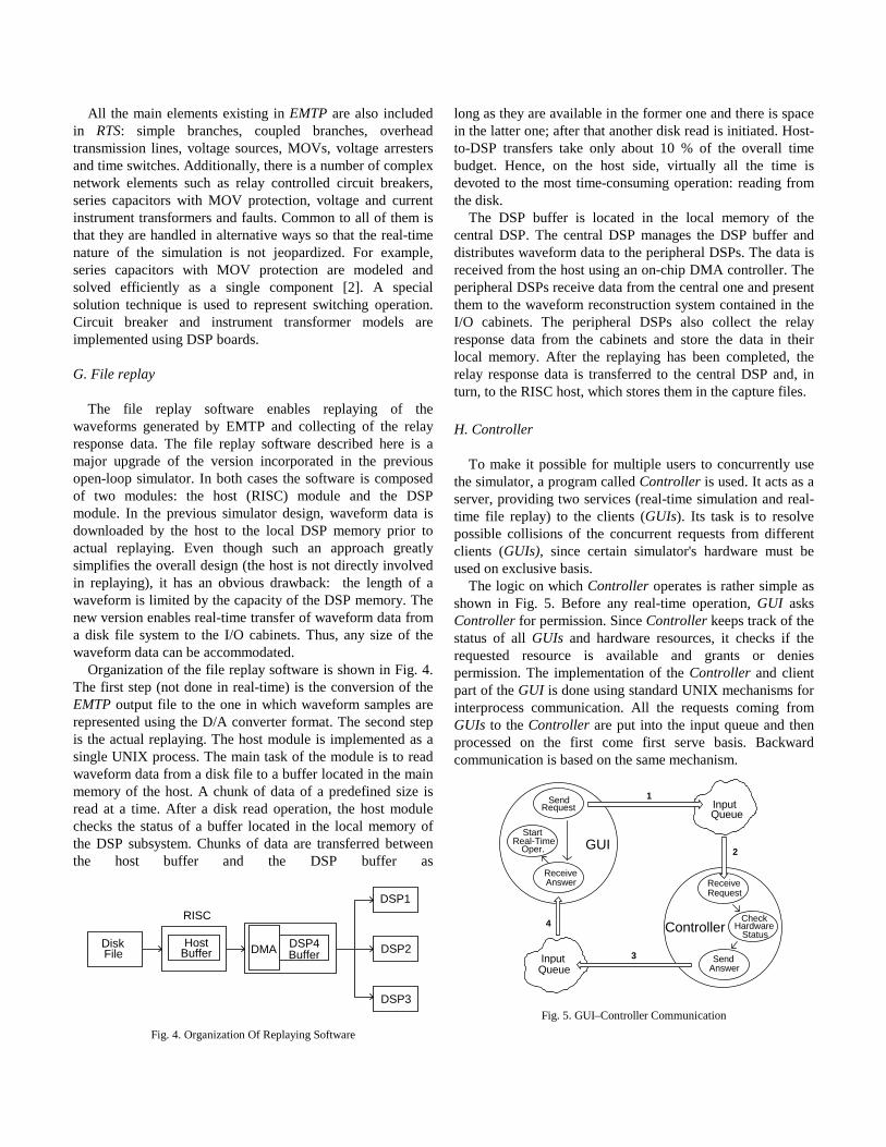
The file replay software enables replaying of thewaveforms generated by EMTP and collecting of the relayresponse data. The file replay software described here is amajor upgrade of the version incorporated in the previousopen-loop simulator. In both cases the software is composedof two modules: the host (RISC) module and the DSPmodule. In the previous simulator design, waveform data isdownloaded by the host to the local DSP memory prior toactual replaying. Even though such an approach greatlysimplifies the overall design (the host is not directly involvedin replaying), it has an obvious drawback: the length of awaveform is limited by the capacity of the DSP memory. Thenew version enables real-time transfer of waveform data froma disk file system to the I/O cabinets. Thus, any size of thewaveform data can be accommodated.
Organization of the file replay software is shown in Fig. 4.The first step (not done in real-time) is the conversion of theEMTP output file to the one in which waveform samples arerepresented using the D/A converter format. The second stepis the actual replaying. The host module is implemented as asingle UNIX process. The main task of the module is to readwaveform data from a disk file to a buffer located in the mainmemory of the host. A chunk of data of a predefined size isread at a time. After a disk read operation, the host modulechecks the status of a buffer located in the local memory ofthe DSP subsystem. Chunks of data are transferred betweenthe host buffer and the DSP buffer as
DiskFile
RISC
HostBufferDMA
DSP3
BufferDSP4
DSP1
DSP2
Fig. 4. Organization Of Replaying Software
long as they are available in the former one and there is spacein the latter one; after that another disk read is initiated. Host-to-DSP transfers take only about 10 % of the overall timebudget. Hence, on the host side, virtually all the time isdevoted to the most time-consuming operation: reading fromthe disk.
The DSP buffer is located in the local memory of thecentral DSP. The central DSP manages the DSP buffer anddistributes waveform data to the peripheral DSPs. The data isreceived from the host using an on-chip DMA controller. Theperipheral DSPs receive data from the central one and presentthem to the waveform reconstruction system contained in theI/O cabinets. The peripheral DSPs also collect the relayresponse data from the cabinets and store the data in theirlocal memory. After the replaying has been completed, therelay response data is transferred to the central DSP and, inturn, to the RISC host, which stores them in the capture files.
H. Controller
To make it possible for multiple users to concurrently usethe simulator, a program called Controller is used. It acts as aserver, providing two services (real-time simulation and real-time file replay) to the clients (GUIs). Its task is to resolvepossible collisions of the concurrent requests from differentclients (GUIs), since certain simulator's hardware must beused on exclusive basis.
The logic on which Controller operates is rather simple asshown in Fig. 5. Before any real-time operation, GUI asksController for permission. Since Controller keeps track of thestatus of all GUIs and hardware resources, it checks if therequested resource is available and grants or deniespermission. The implementation of the Controller and clientpart of the GUI is done using standard UNIX mechanisms forinterprocess communication. All the requests coming fromGUIs to the Controller are put into the input queue and thenprocessed on the first come first serve basis. Backwardcommunication is based on the same mechanism.
InputQueue
Send
Request
Answer
Receive
Check
Status
InputQueue
Start
Request
Real-Time
Send
ReceiveAnswer
Oper.
Hardware
2
1
3
4 Controller
GUI
Fig. 5. GUI–Controller Communication

IV. EXAMPLES OF SIMULATOR OPERATING MODES
This section explains in more detail each of the operatingmodes of the simulator.
A. Closed Loop Operating Mode
In both operating modes the user first builds network byusing Graphical User Interface (GUI). Network description iscontained in the file in ".gui" format. In closed loop mode,described in Fig. 6, GUI then invokes GUI-EMTP software. Itconverts ".gui" file into ".rts" file whose format closelyresembles format of an EMTP input file. After that, GUIstarts EMTP-RTS software that produces two files: ".inp" and".ss". First file contains network data in the specific formatrequested by RTS, and second file keeps steady state solutiondata. To create ".ss" file, EMTP-RTS invokes EMTP.
Prior to the start of the real-time simulation, GUI sends arequest to the Controller. Controller checks if the hardwarethat is to be used is available, and sends an answer. If thepermission is granted, GUI transfers necessary files andinvokes Sequencer. Sequencer starts RTS which outputs itsresults through the DSP subsystem as soon as they arecalculated. Relay responses are used to change the networktopology interactively by the operation of the respective relayterminal(s). At the end of the simulation, Sequencer copiesback the waveform (".wav")and message files (".msg").
GUI-EMTP
RTS
EMTP
RTS
SoftwareDSP
GUIControllerGUI
Sequencer
Conversion
EMTP-RTSConversion
Permission
Request
.wav, .msg .inp, .ss
.OUT
.gui
.rts4
7
3
1
.rts .inp, .ss2
.wav, .msg .inp, .ss5
6
TripSignal
.dat
I/O
Fig. 6. Closed-Loop Operating Mode
B. Open Loop Operating Mode
Fig. 7 shows the involvement of particular softwaremodules in the open loop operating mode of the simulator.
GUI-EMTP
Replay
ArrDat
EMTP
ReplayFile
GUI
Sequencer
Conversion
.pun
2
.out8
.OUT .dat4
.dat
.gui .dat1
ConversionEMTP Results
.out .OUT7
GUIController
Permission
Request
3
.out .OUT6
5
I/O
Fig. 7. Open-Loop Operating Mode
Again, the first step is to build the network by usingGraphical User Interface (GUI). In the next step GUI invokesGUI-EMTP conversion software. It converts ".gui" file into".dat" file whose format is identical to the format of an EMTPinput file. In addition to the conversion used in the closedloop mode, this involves processing of the "include" files andcomponent reordering. Also, during this conversion, EMTPauxiliary program ArrDat might be called to process surgearrester and metal-oxide varistor data.
Since in this operating mode only file replay happens inreal-time, GUI starts EMTP separately. However, it stillcommunicates with the Controller to find out where to runEMTP most efficiently. After the EMTP simulation is done,GUI requests permission from the Controller to start real-timereplay. If the replaying hardware is available, the permissionis granted. GUI then transfers EMTP output file and invokesReplay Sequencer. Sequencer first invokes software thatprocesses raw EMTP results, and then replaying software. Atthe end of the replay, Sequencer copies back the waveformand relay response file.

V. CONCLUSIONS
Simulator description given in this paper leads to thefollowing conclusions:� It is possible to to implement digital simulator design that
is capable of both real-time and open-loop operation� Simulator hardware and system software can be selected
as "off the shelf" products� Graphical User Interface (GUI) can be implemented to
serve as a common interface for both operating modes
VI. ACKNOWLEDGMENTS
The simulator development reported in this paper is fundedby the Commonwealth Edison Company of Chicago undercontract # 811856.
VII. REFERENCES
[1] M. Kezunovic, et. al. ''Transient Computation for Relay Testingin Real-Time", IEEE Transaction on Power Delivery, vol. 9,no. 3, July 1994, pp. 1298-1307.
[2] M. Kezunovic, et. al. ''Computing Responses of SeriesCompensation Capacitors with MOV Protection in Real-Time",IEEE PES Summer Meeting, paper no. 94 SM 400-2 PWRD,San Francisco, July 1994.
[3] M. Kezunovic, et. al. ''Design, Implementation and Validationof a Real-Time Digital Simulator for Protection Relay Testing",IEEE PES Winter Meeting, Paper no. 95 WM 034-9 PWRD,New York, February 1995.
[4] M. Kezunovic, et. al. ''Advanced Signal Processing and FileManagement Software for Relay Testing Using DigitalSimulators", 11th. PSCC, Avignon, France, September 1993.
[5] M. Kezunovic, et. al. ''New Digital Simulator Design forProtective Relay Testing", Texas A&M Relay Conference,College Station, Texas, March 1995.
[6] M. Kezunovic, et. al. ''Extensible Graphical User Interface forDigital Simulators", First International Conference on DigitalSimulators, College Station, Texas, April 1995.
[7] M. Kezunovic, et. al. ''Design Characteristics of and AdvancedTwo-Terminal Digital Simulator for Relay Testing", FirstInternational Conference on Digital Simulators, CollegeStation, Texas, April 1995.
N. A. Izquierdo Jr. (M '76) earned his B.S.E.E. at the IllinoisInstitute of Technology, in 1978. He also completed post-degreemaster's level courses. Mr. Izquierdo began his career withCommonwealth Edison (ComEd) in 1975 in the Relay Section ofthe Operational Analysis Department. In 1978 as a Relay Settingsand application Engineer in the System Planning Department, hewas responsible for relay setting and fault calculation for twoChicago divisions and three generating stations. He also taughtvarious ComEd after-hours protective relay courses. Since 1982, inthe Relay Section of the Operational Analysis Department, he hasbeen responsible for acceptance testing, including design andmanufacture of new protective relays, developing relay test
equipment, investigation and analysis of oscillograms after systemdisturbances, assisting the Regional Operational AnalysisDepartment, General Office Engineering Departments, andlaboratory personnel with special investigations and solutions ofrelay and power system problems. He currently holds the title ofStaff Engineer in the Operational Analysis Department, TechnicalServices-Relay Group. He is a member of the Institute of Electricaland Electronic Engineers.
M. Kezunovic (S'77, M'80, SM'85) received his Dipl. Ing. degree inelectrical engineering in 1974, and the M.S. and Ph.D. degree fromthe University of Kansas, in electrical engineering in 1977 and1980 respectively. His industrial experience is with WestinghouseElectric Corporation in the U.S.A., and the Energoinvest Companyin Sarajevo. His academic experience is with the University ofSarajevo and Washington State University. He has been with TexasA&M University since 1987 where he is an Associate Professor. Heis member of the IEEE PSRC, member of CIGRE and a registeredProfessional Engineer in the State of Texas. Dr. Kezunovic is thechairman of the PSRC working group F-8 on " Digital SimulatorPerformance Requirements".
Z. Galijasevic received his B.S. and M.S. degrees from theUniversity of Sarajevo, Bosnia and Herzegovina, both in electricalengineering, in 1985 and 1992 respectively. From 1985 to 1992 hewas with the Power Electric Institute of the Energoinvest Companyin Sarajevo. In 1993 Mr. Galijasevic joined Texas A&M Universityas a research engineer. His main research interests are in the area ofdigital simulation of electromagnetic transients and computer aidedmeasurement.
F. Ji was born in Henan, China on February 11, 1965. She receivedher B.S. and M.S. degrees in electrical engineering from TianjinUniversity, Tianjin, China in 1985 and 1988 respectively. Ms Ji hadbeen employed with Tianjin University from 1988 to 1991 as ateaching and research assistant. In 1994 she received M.S. degree inelectrical engineering from Texas A&M University. Currently she iswith the Texas Instruments in Houston.
A. Gopalakrishnan received his B.E. degree in Electrical &Electronics Engineering from BITS, Pilani, India in 1989. From1989 to 1992, he was working in The English Electric Co. of IndiaLtd., in Madras, India. Mr. Gopalakrishnan is currently a graduatestudent in EE at Texas A & M University.
J. Domaszewicz earned his M.Sc.E.E. degree from WarsawTechnical University, Poland, in 1986. From 1986 to 1989 he waswith the Department of Electronics at Warsaw Technical University.Mr. Domaszewicz is currently a graduate student at Texas A&MUniversity.