a lightweight rigid-body verlet simulator for real … · a lightweight rigid-body verlet simulator...
TRANSCRIPT

A Lightweight Rigid-Body Verlet Simulatorfor Real-Time Environments
Ben Kenwright
Abstract—In this paper, we present a real-time rigid-body simula-tion technique based upon the popular position-based integrationscheme (Verlet). The Verlet technique has gained popularity dueto its intuitiveness and simulation stability (e.g., coupled soft-body systems, such as, cloths). We explain a simplified techniquebased-upon the Verlet approach for creating a robust rigid-bodysolution for dynamic environments (e.g., objects flying aroundwhile interacting and colliding with one another). What is more,we take the traditional particle-Verlet scheme and expand it toaccommodate both angular and linear components. With thisin mind, we formulate simple constraints (e.g., ball-joints andcollision-contacts) to reconcile and resolve coupled interactions.Our algorithm works by approximating the rigid-body velocities(angular and linear) as the different between the current andprevious states. Constraints are enforced by injecting correctivetransforms that ‘snap’ violating positions and orientations outof error. The coupled rigid-body system is iteratively solvedthrough relaxation to help convergence on an acceptable globalsolution. This addresses the issue of one constraint fightingwith another constraint. We estimate corrective measures anditeratively apply updates to ensure the simulation correlateswith the laws-of-motion (i.e., moving and reacting in a realisticmanner). Our approach targets visually plausible systems, likeinteractive gaming environments, by reducing the mathematicalcomplexity of the problem through ad-hoc simplifications. Finally,we demonstrate our rigid-body system in a variety of scenarioswith contacts and external user input.
Keywords–simulation, verlet, interactive, real-time, rigid-body, colli-sions, constraints
I INTRODUCTION
Interactive Environments Virtual environments are rich withmotion. Highly interactive worlds contain dynamic and complexbodies. Bodies that fly around and bounce off one another.Typically, these scenes need to ‘appear’ detailed and move ina life-like way while running at real-time frame-rates. Theseaction packed scenes have characters falling, stones flying,dust particles swooshing, and trees swaying. While we havean abundance of moving objects, it is also important thatthe user and objects are able to interact with one another.A lightweight solution is sufficient, as we are concerned withaesthetic properties, when buildings collapse, debris and dust isflying around in a dynamic and realistic way. Combined withforces from high-winds and impact explosions to produce anoverall visual effect that is satisfying and captivating. Hence, wedo not need an approach that is highly accurate but aestheticallypleasing.
Interesting & Important An intuitive, stable, and efficientrigid-body simulator is a valuable and important tool for anyreal-time interactive environment. This enables us to createemmersive dynamic worlds. The challenge is to synthesizecoupled and uncoupled motion in a realistic manner efficientlywith less emphasis on physical accuracy. We address engi-neering trade-offs, that trade scientific precision for simplicity
and speed, while maintaining the fundamental rigid-bodymotion mechanics (visually). The Verlet integration schemefor calculating the equations of motion for rigid-bodies mightbe less accurate than other integration methods, but possessesfavourable characteristics (i.e., it is inexpensive, stable and doesnot require the computation of velocities).
Currently At the present time, rigid-body systems primarilyuse Newtonian mechanics to solve the equations of motion(e.g., velocity-impulses, penalty-forces, constrained Lagrangianmechanics) [1]–[4]. The Verlet technique used in this paperhas primarily been used for point-mass systems and soft-bodysimulations (cloths). For interactive media, however, we areless concerned with accuracy but aesthetic qualities. In dynamicsituation (e.g., vehicles colliding, collapsing building, andflying debris), approximations and errors often go unnoticed(intersections and penetrations). Our lightweight approachfocuses on these situations.
Components A simulation is the imitation of the real-worldprocesses and their changes with respect to time. This includesa number of different components that work in synergy, such as,collision detection, resolution, coupled constraints and processparallelisation. We concentrate on the dynamic equations forsimulating real-time interactive situations. The approach isable to solve a variety of common constraint and producesmotions that correlate with physically-accurate models (i.e.,classical mechanic formulations). Techniques include, velocityimpulses, penalty forces, constraint solving methods. Eachrigid-body is subject to a forces and torques (gravity andwind) and constraints (ball-joints and contacts) to preventshapes interpenetrating with each other and the environment.A relaxation technique is used to resolve these ‘concurrent’constraints (help the system converge on a global solution andreduce constraint fighting).
Contributions The key technical contributions of this paperare: (1) the formulation of the Verlet integration scheme foruse in a real-time three-dimensional rigid-body simulator; (2)show that a high precision solution is not essential for mostgaming situation and an uncomplicated second order velocity-Verlet or position-Verlet works well enough; (3) demonstrationof the Verlet method as an effective solution for interactiveenvironments (creating realistic motion for real-time systemsand supporting arbitrary interactions); simulation and (4) theparallelisation of the technique using the graphical processingunit (GPU).
II RELATED WORK
Quantum Mechanics to Interactive Gaming EnvironmentsThe Verlet integration scheme was born in the moleculardynamics field [5], but later gained recognition in otherdomains, such as, computer graphics [6]. During the 2001Game Developer’s Conference, Thomas Jakobsen [7] presented
a simulation technique for point-mass systems, such as, clothesand other soft bodies problems. The particle-Verlet was provenas a viable commercial solution in the video game Hitman:Codename 47 [8] - providing an efficient and stable rag-doll technique (i.e., dead human bodies). Of course, dueto the simplicity and stability of the Verlet technique, theparticle-Verlet method was expanded to include rigid-bodies.Porcino [9] presented a working application of a Verlet-Basedphysics engine. At the same time, Baltman and Radeztsky [10],presented a Verlet integration and constraints system for a sixdegree of freedom rigid-body physics simulation.
On a side note, it can be said that the Verlet technique isa modified impulse solution, since it instantaneous changesthe position and velocity (i.e., velocity impulses). Anotherkey thing to remember is, the basic Verlet integration schemedoes not handle variable frame rates well. However, with asmall modification, we can adapt the technique to account forchanging time-steps.
Verlet Flavours The Verlet integration technique comes inthree basic types (see Section VII for further details):
• Position-Verlet [11]• Leapfrog-Verlet [12], [13] (Leap-frog Verlet method which
is explained clearly by Hut et al. [14]).• Velocity-Verlet
Our Approach We present a method for efficiently modellingcomplex rigid-body interactions in dynamic situations throughlightweight approaches. We employ an ad-hoc solution basedon the popular Verlet-system to reduce overheads yet maintaincore aesthetic qualities. Our lightweight approach eases thememory and computational overhead for less accurate dynamicsituations.
The Newton-Euler formulation [15] for a 6 degrees-of-freedom(dof) rigid body is given by Equation 1:
f = ma
τ = ω × (Iω) + Iα(1)
where f is force, τ torque, m mass, a acceleration, I inertiatensor, ω angular velocity, and α is the angular acceleration.For our simplified approach, we neglect the angular componentfrom the Coriolis (ω × (Iω)) leaving us the simpler Equation2:
f = ma
τ = Iα(2)
III METHOD
Verlet vs Euler (or Runge-Kutta) The advantages anddisadvantages of a technique depend upon its target use. Asan aesthetically pleasing simulation solution is more usefulcompared to a more accurate scientific model for interac-tive gaming environments. The different integration methodsfor interactive physics-based simulation possess numerousadvantages and disadvantages. We show the limitations ofa position-based approach (i.e., modified Verlet technique),including experiments to support and software engineering
workarounds. We investigate the trade-offs between a motionappearing ‘plausible’ but not being realistic due to numericalsimplifications - but provides improved stability in general [15],[16].
Constraints, Collisions, and Contacts One way of reactingto collisions is to use a penalty-based system which basicallyapplies a set force to a point upon contact. The problem withthis is that it is very difficult to choose the force imparted. Usetoo strong a force and objects will become unstable, too weakand the objects will penetrate each other. Another way is touse projection collision reactions which takes the offendingpoint and attempts to move it the shortest distance possible tomove it out of the other object. The Verlet integration wouldautomatically handle the velocity imparted via the collisionin the latter case, however note that this is not guaranteed todo so in a way that is consistent with collision physics (thatis, changes in momentum are not guaranteed to be realistic).Instead of implicitly changing the velocity term, you wouldneed to explicitly control the final velocities of the objectscolliding (by changing the recorded position from the previoustime step). The two simplest methods for deciding on a newvelocity are perfectly elastic collisions and inelastic collisions.A slightly more complicated strategy that offers more controlwould involve using the coefficient of restitution. Our rigid-body Verlet integration (in which velocity is implicit) correctsconstraint violations by implicitly change the angular and linearvelocities (analogous to an applied spring forces).
Connecting Newtonian & Verlet A first order simplecticEuler integration (sometimes called the Euler-Cromer) - thereason the we call the integrator simplectic is the modifiedvelocity (vn+1) is used to update the position - helping toimprove stability (i.e., semi-implicit feedback).
vn+1 = vn + a ∆t
xn+1 = xn + vn+1 ∆t(3)
We approximate velocity as:
v =xn − xn−1
∆t(4)
We substitute this into our simplectic Euler for vn:
vn+1 =
(xn − xn−1
∆t
)+ a ∆t
xn+1 = xn + vn+1 ∆t
(5)
Combining into a single representation for pn+1:
xn+1 = xn + [
(xn − xn−1
∆t
)+ a ∆t] ∆t
= xn +xn − xn−1
∆t∆t+ a (∆t)2
= xn + (xn − xn−1) + a (∆t)2
= 2xn − xn−1 + a (∆t)2
(6)
We are able to calculate the approximated velocities as vn =1
2∆t (xn+1 − xn−1), since having the velocities is frequentlyuseful for some calculations.
Rotation & Translation We use quaternions to represent arigid-body’s rotation. This represention is intuitive especiallyfor the calculation of rotational constraints. The concatenationand difference calculation of quaternions is performed throughmultiplication and conjugate. Using traditional quaternion an-gular integration (see Section VIII), we formulate the equationsfor the rigid-body Verlet:
Translation:xn+1 = xn + (xn − xn−1) + a (∆t)2
Rotation:
qn+1 = qn (qn q∗n−1) +
1
2(α(∆t)2)(qn)
(7)
where a is linear acceleration, α = τI is the angular acceleration,
x represents the translation and q the orientation as a unit-quaternion.
Penalties For traditional Newtonian mechanics, we have thewell known connection between force and torque:
τ = r × f (8)
where τ is the torque, r is the offset from the centre of massto the point we are applying the force f . Equation 8, enablesus to calculate penalty forces at specific points on a rigid-body,so we are able to inject corrective motions.
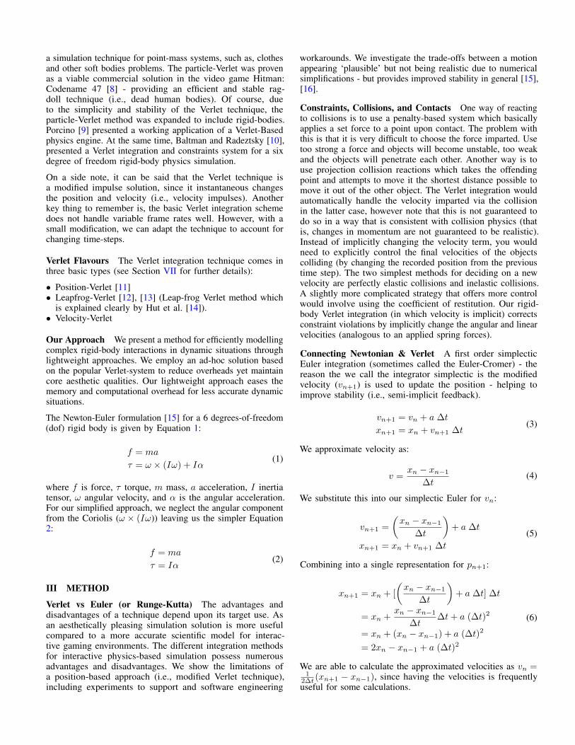
For the particle-Verlet constraint solution, we correct constrainterrors by ‘moving’ (or snapping) each particle’s position outof error. However, for our rigid-body solution, we have botha rotational and translational component. Hence, we use thefounding formula given in Equation 8 to derive Equation 9below (with reference to Figure 1).
∆θ = r × n∆d
∆x = ((r × n∆d) × n) · n (9)
∆x provides the translational penalty, and ∆θ provides theaxis-angle penalty that we convert to a quaternion.
The penalty corrections are applied over multiple iterations incombination with a relaxed over time to provide stability at theexpense of error. This enables the system to converge on anacceptable solution and reduce constraint fighting. As shownin Equation 10 below, we multiple the solution by a scalar crto help the simulation converge. This is especially importantfor coupled problems, multiple contacts and chains of items.
∆θ = (r × n∆d ) cr∆x = (((r × n∆d) × n) · n ) cr
(10)
Velocity-Verlet & Position-Verlet In this paper, we focuson the ‘position-Verlet’ technique, however, there are differenttypes of Verlet integration schemes. A related, and morecommonly used, algorithm is the velocity-Verlet algorithm [17],similar to the Leapfrog method [14], except that the velocity andposition are calculated at the same value of the time variable(Leapfrog does not, as the name suggests). This uses a similarapproach but explicitly incorporates velocity, solving the firsttime step problem in the basic Verlet algorithm.
Figure 1. Penalty Correction - Corrective position and orientation penalty.
Time-Corrected Verlet A disadvantages of the Verlet methodis it handles changing time steps badly, i.e., it is not a self-starter (it requires 2 steps to get going, so initial conditionsare crucial), and it is unclear from the formulation how ithandles changing accelerations. The modified Verlet integratoris referred to as the Time-Corrected Verlet (TCV) and is shownbelow with its original counterpart:
Original Verlet:xn+1 = xn + (xn − xn−1) + a(∆t)2
Time-Corrected Verlet:
xn+1 = xn + (xn − xn−1)∆tn
∆tn−1+ a(∆tn)2
(11)
Damping The Verlet equations can also be modified toincorporate a simple damping component (for instance, toemulate air friction):
Without Damping:xn+1 = 2xn − xn−1 + a(∆t)2
With Damping:xn+1 = (2 − β)xn − (1 − β)xn−1 + a(∆t)2
(12)
where β is the damping coefficient between 0.0 and 1.0. For thequaternion implementation, we integrate in damping in a similarway to the translational damping, but use an interpolationcalculation.
No Silver Bullet Each physics-based technique offers prosand cons, with respect to simplicity, speed, accuracy, andstability - and we find that there is ‘no’ one shoe fit all -a best solution for every situation. However, for interactiveenvironments, such as, video games, the Verlet technique offersprovides certain advantages, as we are interested in astheticqualities - compared to physical accuracy. To summarize, thekey points:
• Pros◦ Quick to process◦ Practically any geometry can be simulated◦ Well suited for soft-body systems◦ Integration with other areas of physics, such as, pool balls
and rope/cloth◦ Time-invariant (play-back)
• Cons◦ Has been described as ‘bouncy’ with few iterations

◦ Inaccuracies develop from relaxation◦ Requires user intervention to get the collision detection
and response to feel right
Pros
Parallelisation We distribute the work load of the simulationby double buffering the simulation parameters. Each rigid-bodyupdates itself and writes its modified position and orientationto the next buffer. Once every rigid-body has updated the nextbuffer, the current and next buffer are swapped and the systemis integrated forward in time (as shown by Westwood et al.[18]).
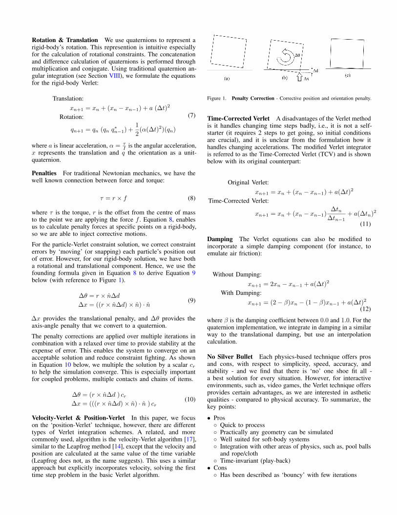
Figure 2. Joint Constraint - Connecting relative rigid-body offsets.
IV EXPERIMENTAL RESULTS
Simulation test-cases:
• single rigid-body falling and bouncing with ground• number of rigid-bodies interacting• chain of interconnected objects (e.g., bridges and ragdolls)• stacking objects• parallelisation of the constraint algorithm by ping-ponging
updates between two copies of memory on the GPU
The technique is simple to implement and moves in a realisticmanner (see Figure 3 and Figure 5). However, as shown inthe simulations, the approach has some issues, for example,long chains of objects settle in a configuration that appearsincorrect (see Figure 2). In our implementation, we did notcache contact points between frames, hence we observed asmall amount of jittering, especially when multiple constraintsinfluence a single rigid-body. For dynamic situations, with lotsof interacting rigid-bodies flying around (see Figure 6, thesimulation produced acceptable results.
V DISCUSSION
Overall the technique is simple to implement and producesasthetically pleasing results in the majority of cases for dynamicsituations. To create more accurate solutions and solve specificcases, such as, stacks and resting bodies, the approach wouldrequire user intervention and tuning of parameters. We didnot include any advanced techniques to help improve thesimulations realism and performance, for instance, shock-propagation, sleeping, and contact caching.
We have concentrated on a rigid-body system, on the otherhand, the approach we present in this paper is easily combinedwith other techniques (particles, deformations, and soft-bodies).
VI CONCLUSION
We propose a lightweight rigid-body simulation method that isstable, fast, and flexible enough for used in real applications,like computer games. Future work would be the developmentof additional constraint types. We also considered the trans-lational and rotational components separately, while a moreesoteric solution to investigate would be the unification of themathematics using dual-quaternions. The creation of a morecomplex joints/constraints types using the Verlet integrationmodel would be useful for simulating intricate systems.
Figure 3. Simple Test Cases - A set of basic simulation tests to show theworking mechanics of motion.
Figure 4. Chain Rigid-Bodies - 21 rigid-bodies connected via ball-jointconstraints. The figure shows how the chain is dropped horizontally andoscillates back-and-forth due to gravity and damping. However, at the end ofthe simulation the chain settles in a straight line (i.e., not the ideal curved arcdue to the weight distribution). We emphasis it here - but point out that in themajority of cases would not be noticed by the user (e.g., in dynamic situationsor a systems with only a few links).
References[1] A. Boeing and T. Braunl, “Evaluation of real-time physics simulation
systems,” in Proceedings of the 5th international conference on Computergraphics and interactive techniques in Australia and Southeast Asia.ACM, 2007, pp. 281–288. 1

Figure 5. Random Cubes - 200 rigid-body cubes falling.
Figure 6. Random Cubes - 1000 rigid-body cubes falling. Our lightweighttechnique is well suited to ‘dynamic’ situations (multiple rigid-bodies flyingaround) - capturing the mechanics of motion and the responsiveness duringimpacts and collisions.
[2] R. Smith et al., “Open dynamics engine,” 2005. 1[3] E. Coumans, “Bullet physics engine,” Open Source Software:
http://bulletphysics. org, vol. 1, 2010. 1[4] A. Bond, “Havok fx: Gpu-accelerated physics for pc games,” in
Proceedings of Game Developers Conference 2006, 2006. 1[5] E. Barth, K. Kuczera, B. Leimkuhler, and R. D. Skeel, “Algorithms for
constrained molecular dynamics,” Journal of computational chemistry,vol. 16, no. 10, 1995, pp. 1192–1209. 1
[6] D. Rozmanov and P. G. Kusalik, “Robust rotational-velocity-verletintegration methods,” Physical Review E, vol. 81, no. 5, 2010, p. 056706.1
[7] T. Jakobsen, “Advanced character physics,” in Game DevelopersConference, 2001, pp. 383–401. 1
[8] Eidos Interactiven, “Hitman: Codename 47,” in Video Game, 2000. 2[9] N. Porcino, “(LucasArts), Writing a verlet-based physics engine,” Game
Programming Gems 4, April 2004, pp. 231–241. 2[10] R. Baltman and R. Radeztsky Jr, “Verlet integration and constraints
in a six degree of freedom rigid body physics simulation,” in GameDevelopers Conference, 2004. 2
[11] D. Ramtal and A. Dobre, “Numerical integration schemes,” in TheEssential Guide to Physics for Flash Games, Animation, and Simulations.Springer, 2011, pp. 443–459. 2
[12] C. Raymaekers, E. CUPPENS, K. CONINX, and L. VANACKEN, “Acomparison of different techniques for haptic cloth rendering,” 2005. 2
[13] G. van den Bergen and D. Gregorius, Game physics pearls. CRC Press,2010. 2
[14] P. Hut, J. Makino, and S. McMillan, “Building a better leapfrog,” TheAstrophysical Journal, vol. 443, 1995, pp. L93–L96. 2, 3
[15] B. Kenwright and G. Morgan, “Practical introduction to rigid bodylinear complementary problem (lcp) constraint solvers,” Algorithmicand Architectural Gaming Design, 2012, pp. 159–205. 2
[16] B. Kenwright, Computational Game Dynamics. Digital Media (ISBN:978-1501018398), 2016. 2
[17] P. F. Batcho and T. Schlick, “Special stability advantages of position-verlet over velocity-verlet in multiple-time step integration,” The Journalof Chemical Physics, vol. 115, no. 9, 2001, pp. 4019–4029. 3
[18] J. D. Westwood et al., “A gpu accelerated spring mass system forsurgical simulation,” Medicine Meets Virtual Reality 13: The MagicalNext Becomes the Medical Now, vol. 111, 2005, p. 342. 4
VII APPENDIX A
Position Verlet Algorithm takes the form:
xn+1 = 2xn − xn−1 + a∆t2
vn =1
2∆t(xn+1 − xn−1)
(13)
Verlet Leapfrog Algorithm takes the form:
vn+1/2 = vn−1/2 + a∆t
xn+1 = xn + vn+1/2∆t
vn+1 =1
2[vn+1/2 + vn−1/2]
(14)
Velocity Verlet Algorithm takes the form:
xn+1 = xn + vn∆t+an2
∆t2
vn+1 = vn + (an+1 + an)∆t
2
(15)
VIII APPENDIX B: QUATERNION INTEGRATION
qn+1 = qn + (dq
dt) dt (16)
dq
dt= limh→0
q(t+ h) − q(t)
h
=1
2ω q
(17)