a design method for drilled piers in soft...
TRANSCRIPT

A design method for drilled piers in soft rock
R. K. ROWE Geotechnicnl Research Centre, Fac~llty of Engineering Science, The University of Western Ontario, London, Ont.,
Canada N6A 5B9
AND
H. H. ARMITAGE Golder Associates, 500 Nottinghill Road, London, Onr., Canacla N6K 3Pl
Received May 20, 1986 Accepted October 16, 1986
A new procedure for the design of drilled piers socketed into soft rock is presented and the selection of design parameters discussed. The design method is based on (I) satisfying a specified design settlement criterion and (2) checking to ensure that there is an adequate factor of safety against collapse. The design allows consideration of the possibility of some slip occurring at the pier-rock interface under working load conditions.
The design procedure is illustrated by a series of detailed calculations relating to two piers in Queenston shale and the observed behaviour of these piers is compared with design expectations. It is shown that these piers satisfied the design settlement criterion while having a significant proven factor of safety against collapse.
Key words: rock, piers, piles, settlement, bearing capacity, design.
Une nouvelle procCdure pour le calcul de pieux forts dans la roche molle est presentee, et le choix de parambtres de calcul est discute. La mCthode de calcul est basCe sur un critkre donne de calcul de tassement, et sur un coefficient de sCcurit6 adCquat contre une rupture complkte. Le calcul permet de prendre en consideration la possibilitC d'un glissement i I'interface pieu-rocher sous des conditions de charge de travail.
La procCdure de calcul est illustrCe par une sCrie de calculs dCtaillCs de deux pieux dans le schiste Queenston; leur comportement observC est compare avec les prCvisions calculCes. L'on montre que ces pieux satisfont aux critbres de tassement calcule tout en ayant un coefficient CprouvC de sCcuritC contre la rupture.
Mots clks : roche, pieux, tassement, capacitC portante, calcul
Can. Geotech. J. 24, 126- 142 (1987) [Traduit par la revue]
Introduction Diameter of Recessed Pier
Historically, the design of drilled piers socketed into rock (referred to herein as socketed piers) has been primarily based on consideration of "bearing capacity" and construction con- straints (Armitage and Rowe 1983). However, procedures for determining the "bearing capacity" of axially loaded drilled piers in rock tend to be crude and conservative, as evidenced by the fact that collapse is rare even in tests intended to deter- mine bearing capacity. Because of the difficulty in causing collapse, "bearing capacity" failure is often associated with the displacement attaining an "excessive" value. Consequently, piers designed on the basis of a de facto limited settlement criterion. (A similar situation exists when considering the bearing capacity of cohesionless sands (see e.g. Peck 1976).)
Recently, a number of researchers have advocated design procedures involving relatively high allowable side shear resistance values (compared with those of earlier empirical design methods) in conjunction with the use of elastic theory for determination of settlement (e.g. Pells and Turner 1979; Horvath 1980; Williams and Pells 1981). In the determina- tion of settlement, these approaches implicitly assume that the available side shear resistance is sufficient to avoid any slip (i.e. failure) at the pier-rock interface under design conditions.
As shown theoretically by Rowe and Armitage (1987), and as demonstrated by the field results of Williams (1980) and Horvath (l980), the majority of the load carried by a socketed pier will be carried in side shear until slip occurs at the inter- face. Once slip occurs, the majority of additional load is then transferred to the base of the socket. In many instances, the shear stress distribution along the socket will be quite non-
Surface
Socket , Base
I E b
Diameter i f Socketed Pier
FIG. I. Notation for a recessed complete socketed pier in rock.
uniform and when consideration is given to the potential vari- ability in side shear resistance itself, it can be expected that under normal conditions (i.e. unless extremely low loads are applied), some slip will occur along the socket irrespective of whether it is considered in design (Rowe and Armitage 1984). Thus it would seem reasonable to adopt a design procedure that does explicitly consider the effect of slip. This paper presents one such approach.
The paper firstly outlines some recent theoretical develop- ments that will allow for consideration of slip in the design of socketed piers. Secondly, selection of design parameters will be considered and a new design method proposed. This ap- proach will then be verified by comparison with the actual behaviour of two piers tested by Horvath (1980). Finally, con-

ROWE AND ARMITAGE: 2
FIG. 2. Elastic settlement influence factors for a complete socketed pier: ( a ) E b / E , = I; ( b ) Eb /E , = 0.5; ( c ) E, /E, = 2.0.
struction considerations such as cleaning and inspection of the rock below) side shear resistance. The pier, of diameter D , sockets are discussed. is bonded to the rock over a length L . The rock has a mass
modulus E , adjacent to this pier and a modulus E , below the Theoretical solutions pier. The pier has a Young's modulus E,.
The general problem being considered is shown in Fig. 1. Initially, assuming that the pier is not recessed (i.e. L , = O), The pier may be recessed to a depth L, below the ground/rock elastic solutions were developed assuming a fully bonded surface. It is assumed that the rock/soil to this depth has a socket using a finite element analysis. The dimensionless modulus E, but does not contribute significant (compared with settlement I defined by

128 CAN. CEOTECH. J . VOL. 24, 1987
FIG. 3. Elastic load distribution curves for a complete socketed pier: ( a ) homogeneous, Eh/E, = 1.0; (b ) E,/E, = 0.5; ( c ) E,/E, = 2.0.
pE,D [ l ] I = -
Q t where p = average settlement of the head of the socket (see Fig. 1 for definition of socket head) and Q, = applied load at the head of the socket, is given in Fig. 2 for a range of geom- etries (LID) and modulus ratios (E,/E,, Eb/E,). The load carried in end bearing, Qb, may be estimated for elastic condi- tions from Fig. 3. (The use of these charts will be described in a later section.)
Recessment of the pier (i.e., LC > 0) will result in a decrease in settlement at the head of the socket (see Fig. 1 ) . This reduc- tion can be expressed in terms of a reduction factor (RF),) such that the settlement at the ground surface is given by
4LcQt Q t
[2] p = - + -1 (RF), .rrD;E, E,D
where I is the influence factor for L, = 0 (see Fig. 2); (RF), is a correction factor for the effect of recessment; D , is the diam-
eter of the pierlpile over the length LC; and all other terms are as previously defined. The first portion of the expression given in [2] simply represents elastic compression of the pier over the length LC. The second portion of the expression gives the settle- ment due to rock deformation. The reduction factor (RF),, is given in Figs. 4 and 5 for a range of situations.
The solutions given in Figs. 2-5 are for the limiting case where no slip occurs along the socket length L (i.e. the pier behaviour is perfectly elastic). The situation where slip can occur at the interface has been examined in detail by Rowe and Armitage (1987). Using an axisymmetric finite element anal- ysis, they developed solutions relating the settlement influence factor I at the head of the pier to the proportion of load trans- ferred to the base of the socket (Qb/Qt) for the situation where partial or complete slip has developed along the socket. A wide range of solutions is given by Rowe and Armitage (1987). A typical set of results is shown (see Fig. 7). The use of these solutions will be described in a later section. The full set of these nonlinear solutions along with the elastic solutions given in Figs. 2-5 provide the theoretical basis for the design method presented in the following section.
Design philosophy The design method described in this paper is intended to
provide a simple, yet rational, hand method for the design of axially loaded drilled piers in soft rock. The approach is based on (1) satisfying a user-specified design settlement criterion (which will govern the design in most cases); (2) ensuring that there is an adequate "factor of safety" against the possibility of collapse. A limit state design philosophy is adopted. Thus, design parameters are obtained by applying partial factors to the ex- pected values of the deformation and strength parameters. The probability of exceeding the design settlement can then be related to the choice of partial factors.
Range of applicability-assumptions The proposed design method is considered appropriate for
socketed piers in rock where ( l ) the load is axial and static in nature (cyclical loading has not been considered); (2) the load is carried in both end bearing and side shear; (3) the base of the pier is in direct contact with the underlying rock and no soft compressible material impairs this contact (cleaning and inspection of sockets will be discussed later); (4) the sides of the drilled shaft are clear of any contamination (e.g. rock smear, drilling mud) that could result in a decrease in peak average side shear resistance at the concrete-rock interface; (5) the sides of the shaft are in either a natural state or arti- ficially roughened; (6) there are no voids or open cavities within the zone of influence of the loaded pier; (7) the expected mass modulus of the rock and average peak side shear resistance at the concrete-rock interface may be estimated either from empirical correlation or from field load tests.
The approach described in this paper is not considered ap- propriate for rock that may be expected to exhibit signifi- cant time-dependent (creep) behaviour at the design loads (e.g. rock salt, gypsum) or for porous rock (e.g. corals) in which crushing, punching, and flexural failure may occur. Also, this

ROWE AND ARMITAGE: 2
FIG. 4. Reduction factors for a recessed socket: (a and b) E,/E, = 10; (c and d) E,/B, = 100.
FIG. 5. Variation insettlement reduction factor with modulus ratio.
paper does not consider factors such as solutioning in lime- stone, chemical swelling, subsidence, etc. that may be critical to the design of foundations in certain situations.
Geological considerations Soft rock will typically be anisotropic and nonhomogeneous,
having variable weathering with depth beneath the rock surface and naturally occurring discontinuities such as joints, seams, faults, and bedding planes (see e.g. Kulhawy and Goodman 1980; Peck 1976). Thus both the deformation and strength characteristics will be directional and will reflect the properties of both the intact rock and the discontinuities. For these reasons it is important that the design parameters be related to actual field behaviour by means of either empirical correlations or, preferably, prototype field tests at the particular site of interest. However, since the mass parameters are dependent on the discontinuities, which may vary appreciably even over a given site, careful consideration of the geological factors is required when selecting design parameters.
Even on an apparently uniform site, statistical variation in parameters may be expected to occur owing to minor local variations in conditions. The design parameters can be selected to allow for this potential variation by applying partial factors to the expected value of the mass parameter (be it the modulus of the rock or the average socket side shear resistance) as described in the following sections.
The roughness of the socket walls will depend on both geo- logical factors, particularly discontinuities, and the construc- tion method used to form the socket. As indicated by Pells et al. (1980), Horvath (1980), and Rowe and Armitage (1984), the roughness of a socket can have a significant influence on the expected side shear resistance. To assist in the selection of parameters for a given situation, the roughness classification R l , R2, R3, and R4 proposed by Pells et al. (1980) and given in Table 1 will be adopted in this paper. Alternative roughness classifications such as that of Horvath could equally well be used and may be correlated with the categories Rl-R4.

130 CAN. GEOTECH. J . VOL. 24, 1987
TABLE I . Roughness classification (after Pells et ell. 1980)
Roughness class Description
R I Straight, smooth-sided socket, grooves or indentations less than l .OO mm deep
R2 Grooves of depth 1 -4 mm, width greater than 2 mm, at spacing 50-200 mm
R3 Grooves of depth 4- 10 mm, width greater than 5 mm, at spacing 50-200 mm
R4 Grooves or undulations of depth greater than 10 mm, width greater than 10 mm, at spacing 50-200 mm
Expected side shear resistance and rock mass modulus Rowe and Armitage (1984) have correlated the socket side
shear resistance, and rock mass modulus, deduced from a large number of field tests with the average unconfined compressive strength for weak rock deposits in which the socket is founded. These correlations, which were developed for rock where there were no open discontinuities within the zone of influence of the socket, may provide an initial estimate of the expected side shear resistance and mass modulus as follows:
[3a] C = 0 . 4 5 6 for regular clean sockets (roughness R1, R2, R3 as defined in Table 1)
[3b] ;i = 0 . 6 6 for clean rough (R4) sockets
[4] E , = 2 1 5 <
where 'i = expected side shear resistance, in MPa; u, = aver- age uniaxial compressive strength of rock core (ASTM D2938), in MPa; and E , = expected rock mass modulus of the rock, in MPa.
A clean socket is classified as a socket where there is no significant auger smear (i.e., zone of remoulded rock), ben- tonite, or other substance that will inhibit good bonding be- tween the rock and concrete. In the absence of direct field test data, side shear resistance should be neglected for any sockets that are not clean. This assumption may be appropriate for smooth sockets but can be quite conservative for sockets with roughness R3 or R4 (see Table I). Even with smear, the side shear resistance of very rough sockets (this includes artificially roughened sockets; see e.g. Horvath (1980)) may be close to that of clean sockets, but the actual available side shear re- sistance should be verified for the ex~ected field conditions
Statistical studies by Rowe and Armitage (1984) have shown that, based on available data, the probability of exceeding a specified design settlement is less than 30% if partial factors f, = f , = 0.7 are adopted and less than 11% forf, = fE = 0.5. The probability of exceeding twice the design settlement is less than 3% in both cases.
To make allowances for potential variability in rock proper- ties with both position and time, it is recommended that a reduction factor of at least 0.7 be applied even when the socketed pier design is based on parameters back-figured from a field test on a prototype pier.
Unless previous testing and experience indicate that the parameters empirically selected on the basis of [3] - [5] are appropriate for a specific site, piers designed on the basis of these parameters should be proof-tested to verify the design.
Allotvable design settlement Careful consideration should be given to the adoption of a
reasonable allowable design settlement. It is well accepted that foundations on soil settle and still perform adequately. The same philosophy should also apply to foundations on rock, recognizing that the majority of the deformations for founda- tions on most rock will occur during construction. (Exception must be made for rocks particularly susceptible to creep.)
It is suggested that the maximum groundline settlement should be selected to be the maximum settlement (at the surface of the soil/rock deposit) that is consistent with good perfor- mance of the structure. The maximum pier head settlement, p,,, , is then calculated by subtracting the compression of the pier or column above the actual socket (e.g. due to the length LC in Fig. I) from the maximum groundline settlement. (Note that the compression of the length LC should be calculated using a concrete modulus and design load that have been factored in accordance with normal limit state design practice.) The design settlement for the socketed pier is then taken to be the max- imum settlement divided by 2, i.e., pd = 0.5 p ,,,.
In the design of socketed piers, differential settlement is likely to be of greater concern than the actual magnitude of the settlement. In general, piers should be designed to ensure that the settlement of each pier will be the same. If differential settlement is critical, the sockets of each pier should be care- fully inspected in the field and the designs adjusted as necessi- tated by differences in the rock at different sockets (e.g. vari- able weathering, seams, etc.).
from a field test. Particular care should be adopted when ben- ANowable etld-bearing pressures tonite is used, as discussed later. There has been considerable debate concerning the bearing
Equation [''I be quite conservative for capWty of circular foundations on rock. Numerous theories roughened sockets. Clearly, higher values may be adopted have been proposed (for a review, see Pells and Turner 1980; when supported by appropriate data. Couetdic and Barron 1975) and there is a significant variation
The most means of determining the side in the predicted bearing capacity. For example, the predicted shear resistance and mass modulus is by performing a field load bearing capacity of a circular footing on rock with + = 350 test On a prototype pier. test may serve to the ranges from to 3zUc depending upon which theory is adequacy of initial empirical estimates of available side shear adopted. The scatter in experimental results is also quite high resistance or to justify the adoption of side shear resistance and the available data does not lend to any values larger than those recommended above. theory. Nevertheless, even adopting the lowest theoretical pre- Design values for side shear resistance and mass modulus diction and applying a factor of safety of 3 would give an
Design values of side shear resistance T,, and rock mass "allowable bearing pressure" of 2 . 7 ~ ~ . This, coincidentally, modulus Ed should be obtained by applying a reduction factor also approximately corresponds to the pressure expected to (or partial factor) f to the expected values of ;i, E,, viz., cause the onset of first failure based on incipient failure theory
[5a] T~ = f,'i (see Pells and Turner 1980). Thus, based on purely theoretical considerations, an allowable bearing pressure at the base of the
[5b] Ed = f E E , pier of 2 . 7 ~ ~ would seem reasonable. (In considering the allow-
ROWE AND ARMITAl
able bearing pressure, it should be remembered that we are only concerned here with preventing significant failure of the rock below the base of the pier. The magnitude of the settlement is considered separately-in the follohing section and depends primarily on the mass modulus of the rock.)
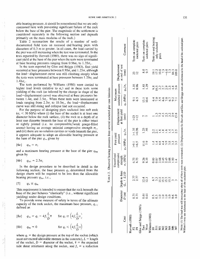
Table 2 summarizes the results of a number of well- documented field tests on recessed end-bearing piers with diameters of 0.3 m or greater. In all cases, the load carried by the pier was still increasing when the test was terminated. In the tests reported by Horvath (1980), there was no sign of signifi- cant yield at the base of the pier when the tests were terminated at base bearing pressures ranging from 0.960, to 1.350,.
In the tests reported by Glos and Briggs (1983), first yield occurred at base pressures between 0.950, and 1.250, although the load-displacement curve was still climbing steeply when the tests were terminated at base pressures between 1.290, and 1 . 4 1 ~ , .
The tests performed by Williams (1980) were carried to higher load levels (relative to u,.) and in these tests some yielding of the rock (as inferred by the change in shape of the load-displacement curve) was observed at base pressures be- tween 1.40, and 2.50,. When these tests were terminated at loads ranging from 2.50, to 10.5u,, the load-displacement curve was still rising and collapse had not occurred.
For the purpose of designing piers socketed into soft rock (0, < 30 MPa) where (i) the base of the socket is at least one diameter below the rock surface, (ii) the rock to a depth of at least one diameter beneath the base of the pier is either intact or tightly jointed (i.e. no compressible/weak gouge-filled seams) having an average uniaxial compressive strength a , , and (iii) there are no solution cavities or voids beneath the pier, it appears adequate to adopt an allowable bearing pressure at the base of the pier q,,, given by
and a maximum bearing pressure at the base of the pier q,,,, given by
In the design procedure to be described in detail in the following section, the base pressure q, determined from the design charts will be required to be less than the allowable bearing pressure q,, , i.e.,
This requirement is intended to ensure that the rock beneath the base of the pier behaves "elastically" (i.e., without significant yielding) under design conditions.
To provide some measure of safety in terms of the ultimate capacity of the rock socket, the maximum base pressure, q,,, defined as
L L [gal q,, = q, - 4/,-i D for q , r (4fsET)
where q , = the design pressure at the top of the socket (which must not exceed allowable stresses in the concrete), L = length of the socket, D = diameter of the socket, i = the expected side shear resistance along the socket, and f, = a reduction

132 CAN. GEOTECH. J . VOL. 24. 1987
factor for ultimate conditions, must be less than the maximum bearing pressure qhnl, i.e.,
For the purposes of design, it is recommended that f , be taken to be 0.3. Based on the statistical studies by Rowe and Armitage (1984), this implies that the probability of the mobi- lized shear resistance being less than that assumed in [8] is less than 0.5%. Thus, [8] is intended to ensure than even if only 30% of the expected side shear resistance was mobilized at the pier-rock interface, the entire pier-socket sustem will still have an adequate factor of safety against collapse.
Note that for lightly loaded piers with long sockets, q,, may be very small. Under these circumstances, [7] will govern.
An acceptable design should satisfy both 171 and [9].
Proposed design procedure A preliminary geotechnical investigation should be under-
taken to assess the in situ conditions of the rock mass and to determine a representative uniaxial compressive strength of the rock as well as to determine any other appropriate parameters. This information can be used together with the design pro- cedure described below to develop a preliminary design. Field tests may then be performed to obtain improved estimates of rock properties and the design can be revised as necessary.
Design of an unrecessed complete socket For a complete socket where the pier is not recessed and no
excessive clay filled or weathered seams exist along the walls of the socket, the design method proceeds as follows (see also Fig. 6):
- STEP l
Select : design settlement . Pd socket diameter, D applied load, Qt [Factored]
Estimate : Modulus of pier, Ep [Factored] Unconfined compressive strength of the rock, Uc
STEP 2 Estimate : expected side shear resistance 7 (e.g. see Eq. 3 )
expected rock mass modulus adjacent to socket ( ag. see Eq. 4 ) expected rock mass modulus beneath socket, Eb
Select : Partial factors to be used in design fT , fE
Calculate : Design s~de shear resistance 7' = fT. ( Eq. 50 ) Design mass modulus Ed= f E . E r (Eq. 5 b )
s r E p 3 Modulus ratios E p / E d , Eb/Er
s r E p 4 ( L / D ) m O x a Q t / ( % ~ 2 ~ d ~
Id ' PdEd D/Qt
re there seams whose presence is not implicitly included in the rock mass modulus and side shear resistance?
I NO Y S
Estimate : Depth .to which seams extend L S Length of socket L i Proportion of seams S = C( seam thickness ) / L i Seam modulus ES Seam side shear resistance Ts
Calculate: €,/Er ; Ts / 7
( L / D $ , ~ ~ = ( L / D l m a X / ( l - ~ + q . s ) ( ~ q . 1 9 )
I; = rd (I-s + SE~IE,) ( ~ q . 21)
7
FIG. 6. Flow chart for the design procedure

ROWE AND ARMITAGE: 2
FIG. 6 . (Concluded).
STEP 5 Determine: ( L / D ) d , ( Q b / Q t ) d from the ~ntersection of the factored
design line for (L/D),,, or ( L / D ) ~ ~ ~ with the contour for Id ( o r 1: ) using des~gn charts allowlng for slip (Rowe 8 Armitage 1987 )
YES I
NO
Determine the value of ( L / D ) d for given Id ( o r 1;) using Fig. 2 Deterrnine the corresponding ( Q b /Qt )d for ( L / D Id using Fig. 3 Determine the recessment length L e
YES
Determine ( RF )p from Fig. 4 or 5 Calculate 1: = Id / ( R F ) p Determine a revised value of ( L / D ) d and ( Qb /Qt Id from Figs. 2 , 3
4 Was a value of ( L / D I d found
I YES
Calculate L = ( L / D ) d . D
STEP 6
q t = Qt / ( ' X D ~ / ~ ) [Eq. 121
4ba = Uc [ ~ q . 131
[ ~ q . 1401 -. 7 = ( I - s + Z . s ) T [ E ~ . l e a ]
7
qbm = 2.5 Uc [Eq. 151
L qbu = st - 4 (E)d fs [ ~ q . 1601
Redesign required Go to step 1
YES
!/
+YES t
NO
Let L I = L S + L o ( calculated above assuming S = 0 i.e. , using Id , ( L / D ) m o x )
Let L 2 = L* (calculated using 12 ) L = m i n ( L I , L 2 )
Deslgn IS Complete

134 CAN. GEOTECH. J. VOL. 24, 1987
loo h _I Factored Design Lsne €b/[ = 1.0
FIG. 7. Design of a complete socketed pier allowing for slip; E,,/E, = 1.
Step I Determine the following design parameters:
(i) allowable design settlement (see previous section), p, (m); (ii) socket diameter, D (m); (iii) applied axial load (factored according to limit state rules), Q, (MN); (iv) modulus of pier (factored according to limit state rules), E, (MPa); (v) unconfined compressive strength of the rock, a, (MPa).
Step 2 (a) Select expected values of side shear resistance and rock
mass modulus by one of the following methods: (i) Using a representative value of u, determined from tests on intact core samples, determine ?. and E , for the rock adjacent to the socket and E b (the modulus of the rock at the base of the pier) from [3] and [4]. (ii) If more - accurate field information is available, then values of E , should be used.
(b) Apply partial factors (i.e., f, and f,) to the expected values found in step 2(a) to obtain the design parameters for side shear resistance and rock mass modulus ([5]). The proba- bility of exceeding the design settlement will depend on the partial factors adopted as indicated in the preceding section.
Step 3 Calculate the dimensionless modulus ratios E,/Ed and
E ~ I E , . Note that the use of the ratio E,/E, (E,/E,) rather than Eb/E, (El lEd) implies that the reduction factorf, is applied to all the rock.
Step 4 (a) Calculate the dimensionless socket length that would be
required if all load was to be carried in side shear:
(b) Calculate the "design" settlement influence factor, I,:
FIG. 8. Design of a complete socketed pier allowing for no slip conditions; E,,/E, = 1.
(c) Estimate S , the percentage of compressible/weak weath- ered seams expected along the shaft of the socket. For S # 0, the values of (LID),,,,, Id may be adjusted as described in the following section. (S = C (seam thickness)/expected socket length L .)
Step 5 This step involves selecting the length of pier required to
give the "design" settlement influence factor I,, while allowing for possible slip at the pier-rock interface. This is achieved by selecting an appropriate design chart for the given values of E,/E, = E,/Ed and E,/E, from those produced by Rowe and Armitage (1987) (e.g., see Fig. 7), and then proceeding as follows:
(a) On the design chart, draw the "factored design line," which is a straight line between the coordinates (LID = 0, Qh/Ql = 100%) and (LID = Ltll;,,ID, Qh/Qt = 0) (see Fig. 7).
(b) Locate the intersection between the "factored design line" and the curve corresponding to the "design" settlement influence factor, I, (see Fig. 7). Then from the intersection point: (i) Draw a vertical line to the L I D axis and read off the "design" length-to-diameter ratio (LID), . Calculate the corre- sponding length L, = (L/D),,*D. (ii) Draw a horizontal line to the Qb/Q, axis and read off the "design" ratio of load carried to the base (Qh/QI),.
If an intersection can be found, then a pier of length Ld will satisfy the design settlement criterion and it simply remains to check that there is an adequate "factor of safety" against over- stressing the rock beneath the pier. Proceed to step 6.
(c) If no intersection point can be established on this design chart, it is necessary to check whether the pier can be designed for the given conditions. Select the appropriate chart from those given as Fig. 2 (e.g., see Fig. 8) and draw a horizontal line for I = I , . Find the intersection of this line with the curve for the

ROWE AND ARMITAGE: 2 135
FIG. 9. Design of a complete socketed pier for no slip conditions; Eh/E , = 1 .
appropriate value of E,/Er = E,/E,: (i) If there is an intersection point on this curve then the pier can be designed elastically (i.e., negligible slip should occur under design conditions). The required (LID), can be obtained by dropping a vertical line from the point of intersection to the LID axis. Calculate the design length L, = (LID),-D. The corresponding proportion of load transferred to the base (Qb/Q,) may be determined from curves given as Fig. 3 by drawing a vertical line from the selected value of (LID), to meet the curve for the appropriate value of E,/E,, then move horizontally to read off the value of (Qb/Ql)d (e.g., see
I i Fig. 9). This pier of length LID satisfies the design settlement I criterion. Proceed to step 6 to check bearing pressures. I (ii) If there is no intersection point then no pier of diameter D
will satisfy the design requirements for the specified condi- tions. Go back to step 1 and either increase the design settle- ment (if the selected value was unrealistically low) or increase the diameter D .
NOTE: In situations where values of E,/E, lie between two design charts (or curves) given by Rowe and Armitage (1987), interpolation will be necessary between the bounding design charts.
To illustrate the three possible situations that may occur in this step, consider a pier with (LID),,,, = 4.5 with E,/E, = 50 and E ~ I E , = 1 (where these values would have been deter- mined in previous steps). In step 5(a), (LID),,,,, = 4.5 is marked on the LID axis and the "factored design line" is drawn between the points (LID = 0, Qb/Q, = 100%) and ((LID),,,,, , Qb/Q, = 0). Now consider three possible values of I,. -If 1, = 0.45 then the intersection point of the factored design line and the curve for I = 0.45 can be found (see Fig. 7) and the values of (LID), = 2.2 and (Qb/Ql), = 5 1 % are read directly from the graph. Proceed to step 6 in this case. -If 1, = 0.25 then an inspection of Fig. 7 shows that there is no intersection point between the factored design line and the curve for I = 0.25 and the procedure described in step 5(c) must be followed. Going to Fig. 8 and drawing a horizontal line forl, = 0.25, an intersection with the appropriate elastic curve for E,/Er = 50 is found at (LID), = 4.7. This pier can be designed elastically (i.e., no slip occurs at the interface). The corresponding value of Qb/Q, can be found from Fig. 9 by moving vertically upwards from (LID), = 4.7 to the curve for E,/Er = 50 and then horizontally to get (Qb/Ql), = 13.5%. Proceed to step 6. -If 1, = 0.15 then an inspection of Fig. 7 shows that there is no intersection point between the factored design line and the curve for I = 0.15 and the procedure described in step 5(c) must be followed. Going to Fig. 8 and drawing a horizontal line
for I = 0.15, we find that there is no intersection of this line with the curve for E,/Er = 50. A pier with this diameter D cannot be designed to satisfy the specified design conditions with I, = 0.15. In this case it is necessary to go back to step 1 and either reassess the choice of allowable settlement p, or adopt a larger pier diameter (or both).
Step 6 This step involves checking that the end-bearing pressure
does not exceed allowable values that were selected to ensure an adequate factor of safety against overstressing the rock below the pier. Calculate:
From earlier recommendations, it is required that
Again, from earlier recommendations, it is required that
(a) If both conditions [14b] and [16b] are satisfied then the design has been controlled by settlement considerations and a suitable pier with length Ld and diameter D has been selected.
(b) If either condition [14b] and [16b] is violated then end bearing controls the design and either the pier length or diam- eter must be increased to reduce the base pressure.
Consideration of weathered seams In soft rocks, soft weathered seams may be encountered
along the shaft of the socket. These seams will generally have a lower modulus and a lower shear strength than the adjacent rock. The effect of these seams will depend on these two properties together with the proportion of seams and the posi- tion of the seams along the socket. Rowe and Armitage (1984) have developed theoretical solutions that allow the designer to examine the effect of seams explicitly. Based on this rigorous analysis, it appears that the effect of seams can be considered using the following approximate methods.
Suppose that an initial estimate of the socket length Li has been obtained (e.g. from a design neglecting seams by fol- lowing steps 1-6) and it is found that weathered seams will exist along the proposed socket.
(a) If these seams are localized to a depth L,, the designer may choose to neglect the portion of the rock with these seams and simply extend the pier to a depth Li below this zone (i.e., the revised length of the pier L , will then be given by
However, if the length L, is a significant proportion of the required length Li then this approach may be far too expensive and an alternative estimate of the required pier length should be determined as described below.
(b) If the seams are evenly distributed down the length of the pier or are localized at some depth L, > D,

136 CAN. GEOTECH. J . VOL. 24. I987
(i) Estimate-The proportion S of seams to total socket length (i.e., S = 2 (seam thicknesses)/L);
-the modulus of the weathered seam material E, (20) ;
-the pier - seam material interface strength T,
(often taken to be zero). (ii) Deduce a modified design side shear resistance, viz.,
and a modified maximum pier geometry
(iii) Deduce a modified modulus
and a new estimate of I:, viz.,
(iv) Repeat steps 5 and 6 as previously described using the modified parameters (LID);,,, I:, and 7: to determine a socket length LZ that will satisfy the design conditions (if no such pier exists, take LZ = m).
(c) Take the total pier length (as measured from the rock surface) to be the minimum of L I and LZ as calculated above.
To illustrate this procedure, consider a pier to be designed for E,/Ed = 50, (LID) ,,,, = 4.5, and 1, = 0.45. Neglecting seams, this pier could be designed as shown in Fig. 7 for (LID), = 2.2 and Q,/Qb = 51%. Suppose that 20% of this socket length is composed of weathered seams (i.e., S = 0.2) with E,/Er = 0.1, 7\17, = 0.1. (i) If the seams are at the top of the socket, L, = 0.2 L i and
If the seams extend approximately to a depth L i , then L, = Li and
(ii) Deduce the modified maximum pier length for full slip design, which becomes
(LID);,, = (LID) ,,,,, l(1 - S + ST,/T) = 5.5
and the new estimate of 1: is
Repeating step 5 using 1: = 0.37 and (LID),,,, = 5.5 then gives (LID), = 3.4 and (Qb/Q,), = 37%. Thus
LZ = 3.40
(iii) If the seams are localized at the top of the pier, take
L = min (L , , L2) = min (2.60, 3 .40) = 2 .60 ,
(Qb/Qt)d = 0.51
If the seams are distributed along the pier,
L = min (4.40, 3.40) = 3 .40 , (Qb/Q,)d = 0.37
The design length 3 .40 was calculated assuming that the seams represent 20% of the final length of the socket. If, in fact, the seams only represent 20% of the top 2.2 m (i.e., the initial length), then the percentage of seams S could be reduced and the calculation repeated to give (after another iteration) Ld = 3 0 , (Qb1Qt),, = 0.40.
Design of n recessecl complete socketed pier If the pier is recessed, it should be initially designed ignoring
recessment by following steps 1-6 above. This design will be conservative for a recessed socketed pier (i.e., where LC # 0). The effect of recessment can be ignored if the pier design involves slip (i.e., if it was designed using figures given by Rowe and Armitage (1987)). However, the design obtained ignoring recessment may be a little too conservative if the pier design does not involve slip (i.e., if it was designed using step 5(c) and curves given in Fig. 2. In this case, the designer may adjust the design to take account of recessment as follows.
Step 5(c) -modified for recessment Determine the following additional design parameters:
(i) recessment length LC (m) and (ii) modulus of the rock adja- cent to the recessed length of the socket (see Fig. 1) E, (MPa), and the corresponding ratios L,/D , E,/Er = E,/E,.
Having determined an initial estimate of (LID), from Fig. 2, determine a settlement reduction factor (RF), from Fig. 4 for the appropriate values of L I D , L,/D, E,/E,, and E,/Er. Adjust the design value of Id as follows:
and then repeat step 5(c) using Figs. 2 and 3 and this revised value of 1: instead of I,. The adjusted value of (LID): should be used to compute a new value of (RF),,. This value may be compared with that initially adopted, and if necessary, step 5(c) may be repeated again for a revised value of 1: calculated with the most recent estimate of (RF),.
Additional comments The design procedure described in the previous section in-
volves selecting a pier geometry such that (1) the probability of exceeding the design settlement pd is acceptably small; (2) the bearing pressure at the base of the pier under design conditions is less than a specified allowable value qhl; (3) the maximum pressure that would develop at the base of the pier if only 30% of the expected side shear resistance were mobilized will not exceed one-third of the estimated base bearing capacity (i.e., qb, < qb,).
Condition ( 1 ) ensures that the serviceability limit state crite- rion is satisfied. Condition (2) is intended to limit yielding of the rock beneath the base of the pier under design conditions.
Normally, one would want the probability of exceeding the design settlement to be less than 30%; this will give a proba- bility of exceeding the maximum allowable settlement (which is twice the design settlement) of less than 3%. Consequently, the expected observed settlement of a pier designed to satisfy conditions (1)-(3) above will be less than the design settlement (i.e., the design settlement is not the settlement that would be predicted for piers with the selected geometry assuming the most probable rock and pier properties).
Considerable research has been conducted into available side shear resistance of concrete sockets under short-term condi- tions (see Rowe and Armitage 1984). However, very little

ROWE AND ARMITAGE: 2
TABLE 3. Design calculations for pier P2
6 ) (ii) Design based on empirically Design based on back-figured
determined parameters parameters
Line Step Quantity Value Notes Value Notes
P'l (m) D (m) Q l (MN) E, (MPa) a, (MPa) ;i (MPa) E , (MPa)
f T
f ,; T~ (MPa) Ed (MPa) E,IE_'i Eh/Er
(L /D )r,,.,x
I* S
(LID
(Qh/Qt)d (LID )<I
(Qh/Ql)d (%) (LID 1,
(Qb/QO* (%I
Ld (m) 41 (MPa) qhil (MPa) 4h (MPa) qbn, (MPa) qhu (MPa) Observed
settlement (m)
"Specified Specified Specified Horvath ( 1980) Horvath (1 980)
"Eq. 1301 Eq. 141 For probability of
exceeding design settle- ment less than 30%
Eq. 15al Eq. 15bI From lines 4 and I I
'Wssume weaker base rock because of fracturing (see text)
Eq. l l O 1 Eq. 11 11 Minor occurrence of seams
based on interpretation of the bore log; neglect effect of seams
'For Eb/E, = I , from Fig. IOa (E,/E, = 100) " ,,
*For Eb /E , = 0.5, from Fig. 10b (E,/E, = 100)
4 , *By linear interpolation
lines 170 and 17b for Eb/E, = 0.75
*Interpolation from lines 18n and 18b
Eq. 1121 Eq. 1131 Eq. [ 141 < qh., .'. OK Eq. 1151 Eq. [I 61 < qh,,, :. OK Less than p,, OK
"Specified Specified Specified Horvath ( 1980) Horvath ( 1980) Back-figured Back-figured Probability of exceeding
design settlement less than 30%
Eq. 15al Eq. 15bl
Effect of weaker base rock included in back- figured parameters
Eq. 1101 Eq. 1111 Effect of any seams
included in the back- figured parametcrs
~ i g : 120 * ,I
"For E,/Ed = 250, Fig. 12b
-F , 'Wy interpolation lines
17n and 176 for E,/E,t = 187
'"Interpolation from lines 18a and 18b
Eq. 1121 Eq. 1131 Eq. 1141 < qh;, :. OK Eq. 1151 Eq. 1 I 61 < y h,,, :. OK Less than p,, OK
NOTE: Items marked * are specifically commented on in the text.
research has been conducted into the long-term load-transfer behaviour of socketed piers. Based on the very limited avail- able data (e.g. Ladanyi 1977; Horvath 1980), it would appear that some additional load transfer to the base of the socket will occur with time owing to the time-dependent characteristics of the rock and concrete. Although there is insufficient data for any firm conclusions to be reached, it may be reasonable to speculate that this time-dependent behaviour will be more criti- cal for smooth than for rough (e.g. R4) sockets. Because of this uncertainty as to exactly how much load will eventually be carried in side shear, condition (3) above is intended to ensure than even if only 30% of the expected side shear resistance is mobilized, there will still be a "factor of safety" of at least 3 against bearing capacity failure of the pier.
When designing piers in rock that is considerably less stiff
than the concrete pier (i.e., E,/E, > lo), to satisfy the settle- ment criteria is quite straightforward and invariably increasing the pier length will reduce settlement. Nevertheless, it may not be possible to design a pier of given diameter and reasonable length ( L I D 5 10) if the settlement criterion is too restrictive. Soft rock should be regarded in a sense as a very strong soil, i.e., presuming that for a given structure constructed on soil a settlement p would be acceptable, then there is no reason why the same settlement p should not be acceptable for the same structure constructed on soft rock. One cannot expect zero settlement for piers constructed on soft rock. Any attempt to achieve negligible settlement will necessarily involve large- diameter piers and low applied pressures; this may be too expensive.
If the concrete pier is only slightly stiffer than the rock (i.e.,

CAN. GEOTECH. I. VOL. 24, 1987
I ~ ' ~ ' ' " ' "
FIG. 10. Determination of design L I D and Q b / Q , values for pier P2; empirical parameters: (LID),,,;,, = 3.4, I,, = 0.53, E,/E, = 1.0 ( a ) , EhIE, = 0.5 (b).
1 5 E,/E, 5 lo), some benefit (in terms of reduced settlement) may be derived from socketing the pier into the rock, however, the benefit of the higher concrete modulus can be partially offset by the weakening of the rock at the concrete-rock inter- face. These competing effects can give rise to a situation where the pier length required to satisfy a given design condition (i.e., to give a specified I ) may not be unique. In these cases, it is generally best to adopt the shorter of the possible design lengths, provided there is adequate end-bearing resistance. If the end-bearing resistance is not adequate, increasing the pier diameter may be preferable to increasing the length of the pier.
Example design calculation To illustrate the use of the proposed design method, consider
the design of a concrete pier (designated as P2) constructed in Queenston shale using rock and concrete data obtained by Horvath (1980) and the empirical correlations for E, and 7, given in this paper. The design parameters are as follows: (i) maximum permissible pier head settlement of p, = 17 mm and hence a design settlement p, = 0 . 5 ~ ~ ~ = 8.5 mm (assumed), (ii) pier diameter D = 0.7 1 m (assumed), (iii) design load Q, = 4.45 MN (assumed), (iv) modulus of the piers, E, = 37 000 MPa (from Horvath 1980), (v) representative unconfined compressive strength of the rock a, = 6.75 MPa (from Horvath 1980).
The design procedure is illustrated under column (i) in Table 3 using the empirical correlations given in [3a] and [4] of this paper for a relatively smooth-sided socket. Thus, (vi) ? = 0 . 4 5 m = 1.17 MPa, (vii) E = 2152/675 = 560 MPa.
The partial factors are chosen to meet a serviceability limit state such that the probability of exceeding the design settle-
ment is less than 30% (i.e., f, = f, = 0.7 (lines 8 and 9 of Table 3)).
The design parameters can then be deduced from [5]: (viii) T~ = 0.7 X 1.17 = 0.82 MPa, (ix) Ed = 0.7 X 560 = 390 MPa, and hence (x) E,/E, = 37 0001390 = 95.
It is assumed here that the pier will be founded in fractured rock (this was in fact the case of Horvath's pier P2) such that the modulus beneath the pier Eb = 0.75Er (line 13). The design parameters (LID),,;,, and Id can then be deduced from [lo] and [I I ] , viz., (xi) (LID) ,,,, = 4.45/(n x 0.71' X 0.82) = 3.4, (xii) I, = (0.0085 X 390 x 0.71)/4.45 = 0.53.
Rowe and Armitage (1 987) have provided design charts for Ep/Ed = 10, 25, 50, 100, and 250 and E,/E, = 0.5, 1.0, and 2.0. For this design, using empirical correlations, the actual value of Ep/Ed = 95 in Table 3 (line 12) is very close to 100 and so only the curves for Ep/Ed = 100 (Fig. 10) were used to deduce the values of (Qh/Q,h in step 5 (lines 17a and 176; 18a and 18b, Table 3). The value for E,,IE, = 0.75 was then obtained (lines 17c and 18c) by linear interpolation be- tween the results for E,/E, = 0.5 and 1 .O. Since 50 < E,/E, < 100, one could also deduce values of (LID), and (Q,/Q,), for Ep/Er = 50 and interpolate between this result and that obtained above for E,/E, = 100. In fact, the values of (LID), and (Qb/Q,), obtained for E,/Er = 50 are 1.9 1 and 44% and it can be seen that in this case no interpolation was necessary to get results for Ep/Ed = 95.
From line 17c, the design length of socket L, = 1.35 m is deduced (line 19).
The allowable end-bearing pressure (q,) and the maximum bearing pressure (q,,,) are then checked against the design recommendations and are found to be adequate (lines 20-24, Table 3). This completes the design.

ROWE AND ARMITAGE: 2 139
A Horizontal
7' Strain Gouges - +
Telltales in Rock Telltales in Pier O
TOP VIEW
~71o"&i+
1 1 /Load Cell N
SECTION A A
FIG. I I. Plan and cross section of geometry for socketed piers P2 and P4 (from Horvath 1980).
Validation of the procedure with reference to Horvath's tests (1980)
Horvath ( 1980) and Horvath et al. ( 1983) performed tests on two end-bearing piers, P2 and P4, which had geometries as shown in Fig. 11. To provide some validation of the design method proposed in this paper, these two piers have been "redesigned" using (i) empirical correlations given in this paper and (ii) parameters back-figured from Horvath's load tests (Table 4). In each case, the design settlement pd has been selected such that the "redesigned" pier has the same dimen- sions as the piers tested by Horvath. The actual performance of the piers can then be directly compared with design expectations.
Comments regarding pier design at location P2 (see Table 3) The socket at location P2 was formed using conventional
drilling techniques and was relatively smooth-sided. For this reason, the empirical correlation given by [3n] was adopted in selecting the expected side shear resistance ?. The redesign of this socket using empirical correlations was described in the previous section and column (i) of Table 3. The corresponding calculations using modulus and side shear values deduced from Horvath's load test (see Table 4) are given in column (ii) of Table 3). In this case, the effect of fracturing in the rock below the pier was not explicitly considered (i.e., the rock was as- sumed to be homogeneous) since the effect of the base is already included in the back-figured modulus, which was de- duced assuming a homogeneous deposit. (This may partly explain the difference between the back-figured rock mass modulus exhibited by sockets P2 and P4 (see Table 4), since there was no fractured rock beneath pier P4.)
For design (ii) the actual value of Ep/Ed = 187 (line 12, Table 3) is not particularly close to the values for which design curves have been given by Rowe and Armitage (1987). Con- sequently, values of (Qb/Q,)d were deduced both for Ep/Ed = 100 and 250 (lines 17a and 17b; 18a and 18b) and the value for Ep /Ed = 187 was then obtained by linear inter- polation (lines 17c, 18c).
To obtain pier geometries comparable with those of the pier P2 actually tested by Horvath, design settlements of 8.5 and
TABLE 4. Relevant design information for socketed piers P2 and P4
Item Socket P2 Socket P4
Average uniaxial compressive stength (at site) for shale, a, (MPa)
Back-figured rock modulus, E,,,Ll, (MPa) Measured peak average side shear
resistance, T~~~~~ (MPa) Roughness category
Modulus of pier concrete (GPa) Length of socketed pier (m) Diameter of socketed pier (m) Recessed pier length (m)
11.5 mm were adopted for the redesign based on (i) empirical correlations and (ii) back-figured parameters respectively. (These design values correspond to maximum allowable settle- ment p,,, = 2pd, i.e., 17 and 23 mm respectively.)
The observed settlement at the head of the socket (i.e., at a depth of 0.6 m) under the design load was 8.4 mm, which, as expected, is less than the design settlement in both cases. Thus both designs may be considered to have performed adequately. In this case, the difference between the design settlement and the observed settlement is greatest for the design based on back-figured parameters. Thus if the same design settlement has been adopted, a design based on back-figured parameters would have given the longer socket (i.e., the more conservative design) for the given conditions.
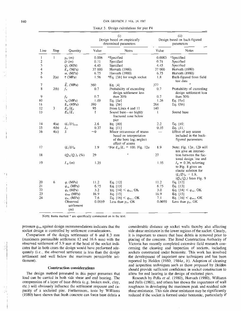
Comrnents regarcling pier design at locatioil P4 (see Table 5) The design settlements pd adopted for the design of socket P4
were 6 and 8.3 mm for the designs based on (i) empirical correlations and (ii) back-figured parameters respectively. The actual socket at P4 was formed using conventional drilling methods but was then artificially roughened (i.e., a roughness R4) using a special pneumatic roughening tool (Horvath 1980). To allow for this roughening, the empirical equation [3b] was used to estimate the expected side shear resistance ? in step 2(a). In fact, the actual socket was considerably rougher than an average "R4" socket and as a consequence the value of ? back-figured from a load test and used in design (ii) is 15% higher than the value given by the empirical correlation.
Since there was no highly fractured zone beneath the bottom of the pier at socket P4, the modulus ratio Eh/E, was taken to be unity. For design (i), based on empirical correlations, E,/E, = 95, and so Fig. 12a was used to estimate with sufficient accuracy the design values (LID),, (Qh/Q,)*. Notice that in this particular case the intersection between the factored design line and the interpolated curve for Id = 0.37 occurs between the dashed curves for elastic behaviour and full slip (T;, ,~/T~ = 1). This implies that this design is based on partial slip along the socket for design conditions where partial factors of 0.7 have been applied to both the side shear resistance and modulus.
For design (ii), based on back-figured parameters, an in- spection of Figs. 12a and 12b shows that there is no inter- section between the factored design line and the curve for I = 0.35. In this case, step 5(c) is required. Referring to Fig. 8, it is seen that for I, = 0.35, Ep/Ed = 95, the pier can be designed elastically (i.e., no slip under design conditions) with (LID), = 1.9. To obtain the proportion of load carried to the base of the socket, reference to Fig. 9 gives (Qb/Q,)d = 27%.
A check of the allowable pressure q, and maximum bearing
140 CAN. GEOTECH. J. VOL. 21. 1987
TABLE 5. Design calculations for pier P4
(i) (ii) Design based on empirically Design based on back-figured
determined parameters parameters
Line Step Quantity Value Notes Value Notes
I I Pd (m) 0.006 *:Specified 0.0083 "'Specified 2 D (m) 0.7 1 Specified 0.7 1 Specified 3 Qt (MN) 4.45 Specified 4.45 Specified 4 E, (MPa) 37 000 Horvath (1980) 37 000 Howath (1980) 5 o, (MPa) 6.75 Horvath (1980) 6.75 Horvath (1980) 6 2(a) 'i (MPa) 1.56 "'Eq. 1301 for rough socket 1.8 Back-figured from field
test data 7 E , (MPa) 560 Eq. L41 377 , 8 2(b) fT 0.7 Probability of exceeding 0.7 Probability of exceeding
design settlement less design settlement less 9 f c 0.7 than 30% 0.7 than 30%
10 T~ (MPa) 1.09 Eq.[5a] 1.26 Eq. [5a] I I Ed (MPa) 390 Eq. 1501 264 Eq. 15b] 12 3 E,IE,, 95 From Lines 4 and 1 1 140 13 E,/Er I Sound base-no highly 1 Sound base
fractured zone below pier
14 4(a) (LID),,,,,, 2.6 Eq. [I01 2.2 Eq. [101 15 4(b) I d 0.37 Eq. [ ] I ] 0.35 Eq. [ I l l 16 4(c) s -0 Minor occurrence of seams - Effect of any seams
based on interpretation included in the baek- of the bore log; neglect figured parameters effect of seams
17 (LID 1.9 "For E,/E, = 100, Fig. 120 1.9 Note: Fig. 12n, 12b will not give an intersec-
18 (QI,/Q!)~ (%) 29 27 tion between the fac- tored design line and
19 Ld (m) I .35 1.35 I,, = 0.36; referring to Fig. 8 gives an elastic solution for (LID),, = 1.9, (Qh/Q,) from Fig. 9
20 6 9 , (MPa) 11.2 ~ q . 1121 11.2 Eel. 1121 2 1 qh., (MPa) 6.75 Eq. [I31 6.75 Eq. [13] 22 ~b ( M k ) 3.2 Eq. 1141 < q,,, OK 3 .O Eq. [I41 < (ih;,, OK 23 4htn (MPa) 16.9 Eq. I151 16.9 Eq. 1151 24 qhu (MPa) 7.6 Eq. 1161 < ql,,,, , OK 7.1 Eq. [I61 < clh.,, OK
Observed 0.0059 Less than p,,, OK 0.0059 Less than pd, OK settkment (m)
NOTE: Items marked * are specifically commented on in the text
pressure qbm against design recommendations indicates that the socket design is controlled by settlement considerations.
Comparison of the design settlements of 6 and 8.3 mm (maximum permissible settlement 12 and 16.6 mm) with the observed settlement of 5.9 mm at the head of the socket indi- cates that in both cases the design would have performed ade- quately (i.e., the observed settlement is less than the design settlement and well below the maximum permissible set- tlement).
Construction considerations The design method presented in this paper presumes that
load can be carried in both side shear and end bearing. The compression of a layer of base debris (e.g. broken rock, clay, etc.) will obviously influence the settlement response and ca- pacity of a socketed pier. Furthermore, tests by Williams (1980) have shown that fresh concrete can force base debris a
considerable distance up socket walls thereby also affecting side shear resistance in the lower regions of the socket. Clearly, it is important to ensure that base debris is removed prior to placing of the concrete. The Road Construction Authority of Victoria has recently completed extensive field research con- cerning the cleaning and inspection of sockets, including sockets constructed under bentonite. This work has involved the development of important new techniques and has been reported by Holden (1980, 1984a, b). Adoption of cleaning and inspection techniques such as those proposed by Holden should provide sufficient confidence in socket construction to allow for end bearing in the design of socketed piers.
Research by Pells et al. (1980), Horvath (1980), Williams and Pells (1981), and others has shown the importance of wall roughness in developing the maximum peak and residual side shear resistance. 'This side shear resistance may be significantly reduced if the socket is formed under bentonite, particularly if

ROWE AND ARMITAGE: 2
-__:35 - -
1
1 2 3 4 5 6 7 8 9 1 0 O ; 4 k b
L - L - D D
FIG. 12. Determination of design L I D and Q,,/Q, values for pier P4: (0) E,,/E, = 100; (17) E,/E, = 250.
the socket is relatively smooth (see e.g. Pells et a/. 1980; Holden 1984a). Frequently, a filter-cake of bentonite will form along the sides of a socket during construction. Experiments by Holden (1984a) have shown that under certain conditions, ben- tonite filter-cake can build up to thicknesses in excess of 100 mm on both mudstones and sandstones. This will reduce the side shear resistance even in relatively rough (or artificially roughened) sockets. Clearly, considerable caution is required in designing socketed piers cast under bentonite. Some recom- mendations for construction procedures to minimize the effect of bentonite filter-cake in these situations have been given by Holden ( 1984a).
In the construction of socketed piers, it is generally advisable to place the concrete as soon as practicable after construction of the socket. Prolonged exposure of the rock socket (particu- larly to water or bentonite) may result in softening of the rock at the concrete-rock interface thereby substantially lowering the available side shear resistance. Research reported by Bamford and Washusen (1981) concerning the softening of Silurian mudstone in contact with water or bentonite has, for example, resulted in a limit of 6 days being placed 03 the time sockets formed in this rock may be exposed to water or ben- tonite without additional reaming (Holden 1984a, b). The ex- tent of exposure required to cause softening will, of course, depend on the type of rock and exposure conditions; however, the potential effects of softening should be considered in any situation where prolonged exposure of the socket occurs prior to casting of the pier.
Concluding discussion A procedure for the design of drilled piers socketed into soft
rock has been proposed. The key equations used in this pro- cedure are summarized in Table 6. The procedure is relatively simple and a socket can be designed in less than 15 min once the designer is familiar with the technique. The design method is based on (1) satisfying a specified design settlement criterion; (2) checking to ensure there is an adequate factor of safety against collapse.
TABLE 6 . Summary of important equations
Equation number Equation
130 I ;i = 0.45 (MPa) [3bl ii = 0.6 6 (MPa) (roughness R4) 141 E , = 2 1 5 6 (MPa) L5al 7 4 =fTfr.? [5bl E,, = f ,;-E, I101 ( L I D = Q I / ( n D 2 ~ d ) 1 1 1 1 Id = P&,IDIQ, 1121 91 = Q l l ( n D v 4 ) L131 qhi, = [14al qh = (Qb/Qt)d(lt 11461 qb 5 qh;, for satisfactory design 1151 yh,,, = 2 . 5 ~ ~ 116al qh,, = 4 1 - 4 f ; (L /D)d? (f, = 0.3) 116bI y,,, 5 qh,,, for satisfactory design 1171 L , = L , + L , L18al 7 :I: = ( I - s + ST./T)?
118b1 ;i: = f T .?:"
1191 (LID)?,,,, = (L/D),,,.,,/(1 - S + ST,/?) 1201 E:; = ( I - s + SE, /E , )E , 12 1 I I: = (pdE,*D)/Ql = I d ( l - S + SE, /E , )
The design method has been illustrated by a series of detailed calculations relating to the sockets P2 and P4 tested by Horvath (1980) in Queenston shale. These calculations show that piers designed to have the same geometry as those tested by Horvath (1980) would have satisfied the design settlement criteria while having a proven "factor of safety" against collapse of at least 2. (Since the test piles were not brought to collapse the actual "factor of safety" is unknown.) Similar comparisons conducted by Rowe and Armitage (1984) for a number of other field cases documented by Glos and Briggs (1983) and Williams (1980) have shown similar encouragement. However, as always, care- ful consideration should be given to the geological conditions at any specific site when designing piers in rock and field load tests should be conducted to verify design assumptions when- ever unusual conditions or uncertainties exist.

142 CAN. CEOTECH. J . VOL. 24. 1987
Acknowledgements Research Council of Canada, DSS file no. 10X5.31155-9-4420, "
The research described in this paper was supported by the Department of Supply and Services Canada and the National Research Council of Canada under contract no. ISU83-00082.
Many thanks are due Dr. M. Bozozuk, of the National Research Council, who acted as Scientific Advisor on this project. Thanks are also due Mr. P. J. N . Pells for many useful discussions over many years and to Dr. F. Kulhawy for his very useful comments on the manuscript.
ARMITACE, H. H., and ROWE, R. K. 1983. Current practice for the design of socketed piles: Response to a survey. Faculty of Engi- neering Science, The University of Western Ontario, London, Ont., Research Report GEOT-4-83.
BAMFORD, N. E., and WASHUSEN, J. A. 1981. Weakening caused by fluids used for drilling mudstones. Proceedings of International Symposium on Weak Rock, Tokyo.
COUETDIC, J. M., and BARRON, K. 1975. Plate-load testing as a method of assessing the in situ strength properties of Western Cana- dian coal. International Journal of Rock Mechanics and Mining Sciences, 12(10), pp. 303-310.
GLOS, G. H., 111, and BRICCS, 0 . H., JR. 1983. Rock sockets in soft rock. ASCE Journal of Geotechnical Engineering, 109(4), pp. 525-535.
HOLDEN, J. C. 1980. Development of a socket inspection device. Proceedings of the International Conference on Structural Founda- tions on Rock, Sydney, Vol. 2, pp. 91 -95.
1984a. Construction of bored piles in weathered rocks. Road Construction Authority of Victoria, Melbourne, Australia, Tech- nical Report no. 69.
1984b. The construction of bored piles in weathered sedimen- tary rock. Proceedings of 4th Australia and New Zealand Confer- ence on Geomechanics, Perth, pp. 1-7.
HORVATH, R. G. 1980. Research project report on load transfer sys- tem for rock-socketed drilled pier foundations. For the National
contract serial no. lSX79.0053 1 . HORVATH, R. G., KENNEY, T. C., and KOZICKI, P. 1983. Methods of
improving the performance of drilled piers in weak rock. Canadian Geotechnical Journal, 20(4), pp. 758-772.
KULHAWY, F. H., and GOODMAN, G. E. 1980. Design of foundations on discontinuous rock. Proceedings of the International Conference on Structural Foundations on Rock, Sydney, Vol. I, pp. 209-222.
LADANYI, B. 1977. Friction and end bearing tests on bedrock for high capacity socket design: Discussion. Canadian Geotechnical Journal, 14(1), pp. 153-155.
PECK, R. B. 1976. Rock foundations for structures. Rock Engineering for Foundations and Slopes, Proceedings of a Specialty Conference, ASCE, Vol. 11, Boulder, CO, pp. 1 -2 1 .
PELLS, P. J. N., and TURNER, R. M. 1979. Elastic solutions for the design and analysis of rock-socketed piles. Canadian Geotechnical Journal, 16(3), pp. 48 1 -487.
1980. Endbearing on rock with particular reference to sand- stone. Proceedings of the International Conference on Structural Foundations on Rock, Sydney, Vol. 1, pp. 181 - 190.
PELLS, P. J. N., RowE, R. K., and TURNER, R. M. 1980. An experi- mental investigation into sideshear for socketed piles in sandstone. Proceedings of the International Conference on Structural Founda- tions on Rock, Sydney, Voi. I, pp. 291 -302.
ROWE, R. K., and ARMITAGE, H. H. 1984. The design of piles socketed into weak rock. Faculty of Engineering Science, The University of Western Ontario, London, Ont., Research Report GEOT- 1 1-84.
1987. Theoretical solutions for axial deformation of drilled shafts in rock. Canadian Geotechnical Journal, 24, this issue.
WILLIAMS, A. F. 1980. The design and performance of piles socketed into weak rock. Ph.D. thesis, Monash University, Melbourne, Australia.
WILLIAMS, A. F., and PELLS, P. J. N. 1981. Side resistance rock sockets in sandstone, mudstone, and shale. Canadian Geotechnical Journal, 18(4), pp. 502-5 13.