gonzalez-strength and associates, inc. 2176 parkway … drilled straight ... specification for the...
TRANSCRIPT

Terracon Consul tants, Inc. 2147 Riverchase Off ice Road B irmingham, Alabama 35244P [205] 942-1289 F [205] 443- 5302 terracon.com
April 6, 2018
Gonzalez-Strength and Associates, Inc.2176 Parkway Lake DriveBirmingham, Alabama 35244
Attn: Mr. Douglas R. Peterson, P.E.
Re: Signal Pole Foundation ReportAdditional Lanes and Widening on SR-2 (US-278)From West of County Line Road to Crutcher RoadAnd on County Line Road and Old Railroad Bed RoadIn The City of HuntsvilleGrade, Drain, Base, Pave, Signing, and SignalsMadison and Limestone Counties, AlabamaTerracon Project No. E1165145
Dear Doug:
Terracon is pleased to present this signal pole foundation report for the above-referencedproject. Our scope for this project was performed in general accordance with our proposalnumber PE1165145 dated March 31, 2016. The following report presents the results of our fieldprocedures, an evaluation of the subsurface conditions with respect to available projectcharacteristics, and recommendations to aid in the design and construction of the proposedsignal pole foundations. We appreciate the opportunity to be of service to you on this project. Ifyou have any questions concerning this report, or if we may be of further service, please contactus.
Sincerely,Terracon Consultants, Inc.
Matthew S. McCullough, P.E. Jerome A. Smith, P.E.Project Engineer Manager, Geotechnical ServicesAlabama PE 26344 Alabama PE 20478
Attachments: Exhibit A-1: Site Location PlanExhibits A-2: Geologic MapExhibit A-3: Boring Location PlanPassive Pressure Diagram Sheets (2)Test Boring Record Sheets (2)

Signal Pole Foundation ReportAdditional Lanes and Widening on SR-2 (US-72) from West of County Line RoadTo Crutcher Road ■ Madison and Limestone Counties, AlabamaApril 6, 2018 ■ Terracon Project E1165145
Responsive ■ Resourceful ■ Reliable 2
GEOLOGICAL SURVEY
Published maps indicate that the project is underlain by the Fort Payne Chert. This formationcontains very light to light-olive-gray, thin to thick-bedded fine to coarse-grained bioclastic(abundant pelmatozoans) limestone containing abundant nodules, lenses and beds of light todark-grey chert.
FIELD EXPLORATION
The field exploration consisted of performing Standard Penetration Test (SPT) boring near eachof the four (4) signal pole locations. These locations were staked by our client in the field prior toour mobilization. It should be noted that the project plans have been changed since the boringswere performed in 2013, but we anticipate the new signal pole locations will remain in thegeneral vicinity of our borings. The attached Site Location Plan indicates the approximatelocation of the site. The boring locations are depicted on Exhibit A-3 (Boring Location Plan).
The sampling and penetration procedures of the SPT borings were accomplished using a powerrotary drill rig and were performed in accordance with ASTM D-1586. The standard penetrationtests were performed by driving a standard 1-3/8” I.D. and 2” O.D. split spoon sampler with a140-pound hammer falling 30 inches. The number of hammer blows required to drive thesampler a total of 18 inches was recorded in 6-inch increments. The penetration resistance (N-value) is the summation of the last two 6-inch increments and is illustrated on the attachedboring logs adjacent to the corresponding depths. The N-values are used as an index to derivesoil parameters from various empirical correlations.
The borings typically penetrated lean clays or fat clays of moderate to high-plasticity and low-plasticity clayey sand. These soils were medium stiff to hard or dense, with standard penetrationresistance (N-values) of 6 to 57 blows per foot (bpf).
The boreholes were observed while drilling and after completion for the presence and level ofgroundwater. Groundwater was observed at the time of drilling at the depths shown in thefollowing table.
Boring No. Depth Groundwater Observed(feet)
Elevation Groundwater Observed(feet)
P-1 18.0 719.0P-2 13.5 719.5P-3 15.0 720.5P-4 18.0 716.5
Due to the low to moderate permeability of the soils encountered in the borings, a relatively longperiod of time may be necessary for a groundwater level to stabilize in a borehole in these

Signal Pole Foundation ReportAdditional Lanes and Widening on SR-2 (US-72) from West of County Line RoadTo Crutcher Road ■ Madison and Limestone Counties, AlabamaApril 6, 2018 ■ Terracon Project E1165145
Responsive ■ Resourceful ■ Reliable 3
materials. Long term observations in piezometers or observation wells sealed from the influence ofsurface water are often required to define groundwater levels in materials of this type.
Groundwater level fluctuations occur due to seasonal variations in the amount of rainfall, runoffand other factors not evident at the time the borings were performed. Therefore, groundwaterlevels during construction or at other times in the life of the structures may be higher or lowerthan the levels indicated on the boring logs. The possibility of groundwater level fluctuationsshould be considered when developing the design and construction plans for the project.
For a more detailed description of the subsurface strata encountered, please refer to theattached Test Boring Record Sheets. The stratification lines on the boring logs representapproximate boundaries between major soil and rock types as interpreted by the engineer. Theactual transitions may be gradual.
RECOMMENDATIONS
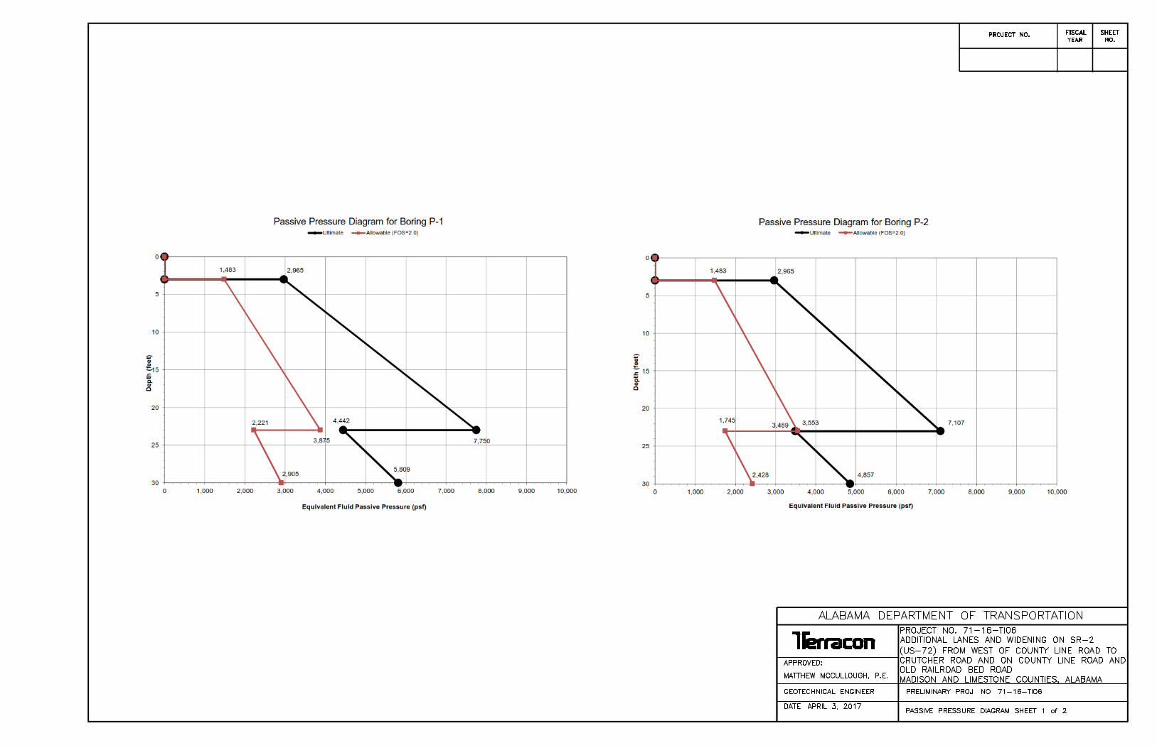
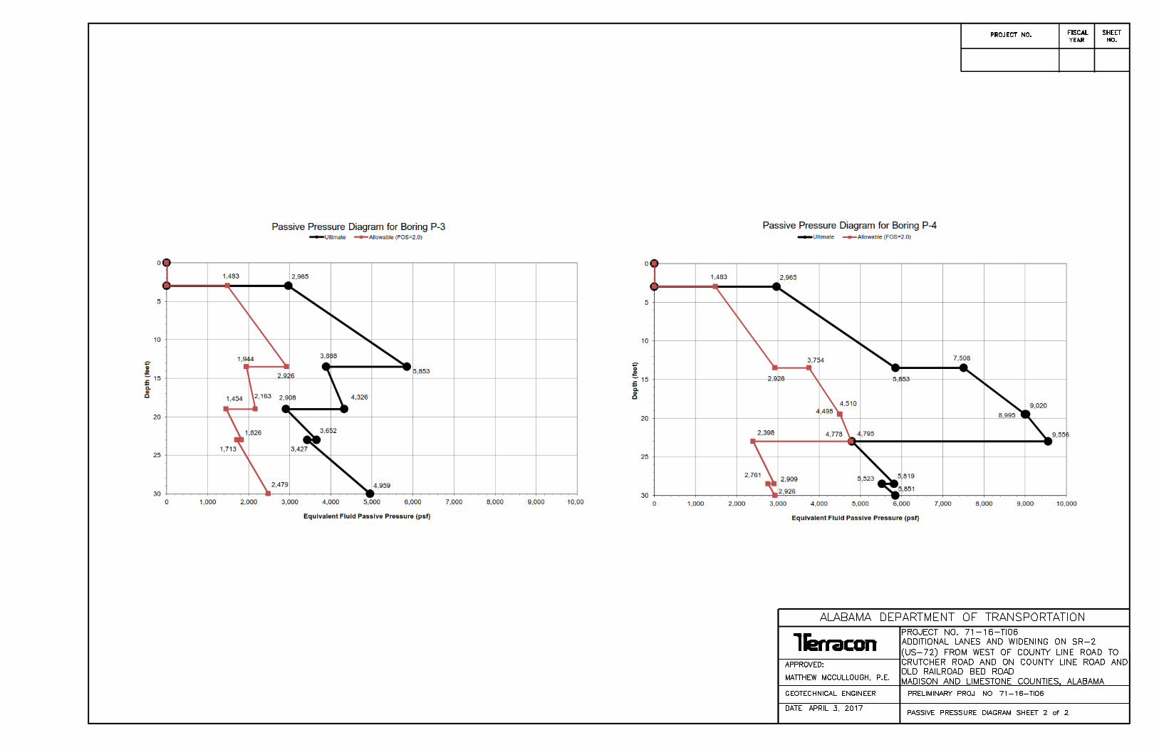
Engineering values for each soil strata encountered by our borings at the signal pole locationsare presented in the following tables for use in designing drilled straight-shaft foundations. Also,we have attached the recommended passive pressure diagrams.
Boring P-1DepthBelow
ExistingGrade
(ft)
MaterialDescription
NetAllowable
EndBearingPressure
(psf)
AllowableSide
Friction(psf)
EffectiveUnit
Weight(pcf)
Cohesion(psf)
FrictionAngle
(degrees)
Strainat 50%(E50)
HorizontalSubgrade
Modulus (k)(pci)
0 – 3 Lean Clay(hard) --- --- --- --- --- --- ---
3 – 8.5 Lean Clay(very stiff) 2,500 250 125 1,000 22 0.007 200
8.5 – 13 Fat Clay(stiff) 2,500 250 125 1,000 22 0.007 200
13 – 18.5 Lean Clay withChert (stiff) 2,500 250 125 1,000 22 0.007 200
18.5 – 23Sandy Lean Clay
with Gravel(very stiff)
2,500 250 125 1,000 22 0.007 200
23 – 30 Clayey Sand withGravel (dense) 4,000 650 125 --- 32 --- 500

Signal Pole Foundation ReportAdditional Lanes and Widening on SR-2 (US-72) from West of County Line RoadTo Crutcher Road ■ Madison and Limestone Counties, AlabamaApril 6, 2018 ■ Terracon Project E1165145
Responsive ■ Resourceful ■ Reliable 4
Boring P-2
Boring P-3
DepthBelow
ExistingGrade
(ft)
MaterialDescription
NetAllowable
EndBearingPressure
(psf)
AllowableSide
Friction(psf)
EffectiveUnit
Weight(pcf)
Cohesion(psf)
FrictionAngle
(degrees)
Strainat 50%(E50)
HorizontalSubgrade
Modulus (k)(pci)
0 – 3Sandy Lean Clay
with Chert(very stiff)
--- --- --- --- --- --- ---
3 – 6Sandy Lean Clay
with Chert(very stiff)
2,500 250 125 1,000 22 0.007 200
6 – 8.5 Sandy Lean Clay(very stiff) 2,500 250 125 1,000 22 0.007 200
8.5 – 13 Sandy Lean Clay(stiff) 2,500 250 125 1,000 22 0.007 200
13 – 19Sandy Lean Clay
with Gravel(stiff)
2,500 250 125 1,000 22 0.007 200
19 – 23Sandy Lean Clay
with Gravel(very stiff)
2,500 250 125 1,000 22 0.007 200
23 – 30 Clayey Sand withGravel (dense) 4,000 650 125 --- 32 --- 500
DepthBelow
ExistingGrade
(ft)
MaterialDescription
NetAllowable
EndBearingPressure
(psf)
AllowableSide
Friction(psf)
EffectiveUnit
Weight(pcf)
Cohesion(psf)
FrictionAngle
(degrees)
Strainat 50%(E50)
HorizontalSubgrade
Modulus (k)(pci)
0 – 3 Lean Clay(very stiff) --- --- --- --- --- --- ---
3 – 8.5 Lean Clay(very stiff) 2,500 250 125 1,000 22 0.007 200
8.5 – 13.5Sandy Lean Clay
with Chert(very stiff)
2,500 250 125 1,000 22 0.007 200
13.5 – 19Sandy Lean Clay
with Chert(medium stiff)
1,000 200 125 500 --- 0.01 100
19 – 23Clayey Sand with
Gravel(medium dense)
3,000 500 125 --- 28 --- 250
23 – 30 Clayey Sand withGravel (dense)
4,000 650 125 --- 32 --- 500

Signal Pole Foundation ReportAdditional Lanes and Widening on SR-2 (US-72) from West of County Line RoadTo Crutcher Road ■ Madison and Limestone Counties, AlabamaApril 6, 2018 ■ Terracon Project E1165145
Responsive ■ Resourceful ■ Reliable 5
Boring P-4
The design parameters presented in the tables above and on the attached passive pressurediagrams are applicable for the soils encountered at the specific boring locations. The endbearing, skin friction, and passive resistance are allowable parameters with factors of safety of3, 2, and 2, respectively. The values given in the tables are based on our borings and pastexperience with similar soil types. Lateral resistance and friction in the upper 3 feet should beignored due to the potential effects of frost action, desiccation, and drilling disturbance. Drilledstraight-shaft foundations should extend at least 3 feet into the desired bearing strata in order touse the recommended allowable end bearing pressures.
The drilling contractor should be experienced in the subsurface conditions observed at the site,and the excavations should be performed with equipment capable of providing a clean bearingarea. The drilled straight-shaft foundation should be installed in general accordance with theprocedures presented in "Drilled Shafts: Construction Procedures and Design Methods," byReese, L. C. and O’Neill, M. W., FHWA Publication No. FHWA-IF-99-025, 1999 and "StandardSpecification for the Construction of Drilled Piers", ACI Publication No. 336.1-01, 2001.
Casing may be required during construction of the drilled shafts. A sufficient head of plasticconcrete having a minimum slump on the order of 6 inches should be maintained inside thecasing as it is being withdrawn to prevent an influx of soil and debris into the excavation andconcrete arching inside the casing. To facilitate pier construction, concrete should be on-siteand ready for placement immediately after each pier excavation is completed.
DepthBelow
ExistingGrade
(ft)
MaterialDescription
NetAllowable
EndBearingPressure
(psf)
AllowableSide
Friction(psf)
EffectiveUnit
Weight(pcf)
Cohesion(psf)
FrictionAngle
(degrees)
Strainat 50%(E50)
HorizontalSubgrade
Modulus (k)(pci)
0 – 3 Lean Clay(very stiff) --- --- --- --- --- --- ---
3 - 6 Lean Clay(very stiff) 2,500 250 125 1,000 22 0.007 200
6 – 9 Lean Clay withChert (very stiff) 2,500 250 125 1,000 22 0.007 200
9 – 13.5Sandy Lean Clay
with Chert(very stiff)
2,500 250 125 1,000 22 0.007 200
13.5 – 19.5 Lean Clay(hard) 4,000 400 125 1,500 24 0.004 300
19.5 – 23 Lean Clay(very stiff) 2,500 250 125 1,000 22 0.007 200
23 – 28.5Clayey Sand with
Gravel(medium dense)
3,000 500 125 --- 28 --- 250
28.5 – 30 Clayey Sand withGravel (dense) 4,000 650 125 --- 32 --- 500

Signal Pole Foundation ReportAdditional Lanes and Widening on SR-2 (US-72) from West of County Line RoadTo Crutcher Road ■ Madison and Limestone Counties, AlabamaApril 6, 2018 ■ Terracon Project E1165145
Responsive ■ Resourceful ■ Reliable 6
Because the subsurface conditions could vary away from the boring location, we recommendthat the geotechnical engineer or his representative observe the pier installations to evaluate theintended bearing material is encountered and sufficiently penetrated.

SITE LOCATION MAPADDITIONAL LANES AND WIDENING ON SR-2(US-72) FROM WEST OF COUNTY LINE ROAD
TO CRUTCHER ROADMADISON AND LIMESTONE COUNTIES
Huntsville, AL
TOPOGRAPHIC MAP IMAGE COURTESY OF THE U.S. GEOLOGICAL SURVEYQUADRANGLES INCLUDE: CAPSHAW, AL (1/1/1982) and GREENBRIER, AL (1/1/1992).
110 12th St NBirmingham, AL 35203-1537
E1165145Project Manager:
Drawn by:
Checked by:
Approved by:
MSM
JAS
JAS
1”=2,000’
4/6/2017
Project No.
Scale:
File Name:
Date:A-1
ExhibitMSM
SITE

Fort Payne Chert - Very light to light-olive-gray, thin to thick-bedded fine to coarse-grained bioclastic (abundant pelmatozoans)limestone containing abundant nodules,lenses and beds of light to dark-grey chert.
Hartselle Sandstone - Light-colored thick-bedded to massive quartzose sandstone,containing interbeds of dark-gray shale.
GEOLOGIC MAPADDITIONAL LANES AND WIDENING ON SR-2(US-72) FROM WEST OF COUNTY LINE ROAD
TO CRUTCHER ROADMADISON AND LIMESTONE COUNTIES
110 12th St NBirmingham, AL 35203-1537
DIAGRAM IS FOR GENERAL LOCATION ONLY, AND ISNOT INTENDED FOR CONSTRUCTION PURPOSES
E1165145
MSM
JAS
JAS
NTS
4/6/2017
Scale:
A-2
ExhibitProject Manager:
Drawn by:
Checked by:
Approved by:
Project No.
File Name:
Date:
MSM
SITE

DIAGRAM IS FOR GENERAL LOCATION ONLY, AND IS NOTINTENDED FOR CONSTRUCTION PURPOSES
110 12th Street North Birmingham, Alabama 35203
PH. (205) 942-1289 FAX. (205) 443-5302
A-3
EXHIBITBORING LOCATION PLANADDITIONAL LANES AND WIDENING ON SR-2(US-72) FROM WEST OF COUNTY LINE ROAD
TO CRUTCHER ROADMADISON AND LIMESTONE COUNTIES
Project Manager:
Drawn by:
Checked by:
Approved by:
MSM
MSM
JAS
JAS
Project No.
Scale:
File Name:
Date:
E1165145
4/6/2017
NTS
P-4
BORING LOCATION
P-1
P-2
P-3