a dependence representation for coverage testing of object
TRANSCRIPT
Journal of Object TechnologyPublished by ETH Zurich, Chair of Software Engineering, c© JOT 2010
Online at http://www.jot.fm.
A Dependence Representation forCoverage Testing of Object-Oriented
Programs
E.S.F. Najumudheena Rajib Malla Debasis Samantab
a. Department of Computer Science and EngineeringIndian Institute of Technology, Kharagpur, India
b. School of Information TechnologyIndian Institute of Technology, Kharagpur, India
Abstract We propose a dependence-based representation for object-or-iented programs, named Call-based Object-Oriented System DependenceGraph (COSDG). Apart from structural features, COSDG captures im-portant object-oriented features such as class, inheritance, and polymor-phism. Novel features of COSDG include details of method visibility in aderived class, and different types of method call edges to distinguish be-tween various calling contexts—simple, inherited, and polymorphic. Wealso propose an algorithm for the construction of COSDG, and subse-quently explain its working with an example. COSDG has been devel-oped primarily to aid test coverage analysis. However, it can be used in avariety of other software engineering applications such as program slicing,software re-engineering, and debugging.
Keywords Coverage analysis, program representation, software testing,object-oriented programs.
1 Introduction
Various software techniques such as test coverage analysis, program slicing, programdebugging, software re-engineering, and compiler optimization convert a program intoa suitable intermediate representation by code analysis, and use it for subsequentoperations. An intermediate representation is essentially a model of a program thatcaptures those characteristics that are relevant to a specific task while abstractingout the rest.
A variety of models have been proposed in the past to represent various featuresof programs. Control flow graph (CFG) [2, 6], data flow graph (DFG) [16, 6], programdependence graph (PDG) [6], system dependence graph (SDG) [8], and call graph (CG)
E.S.F. Najumudheen, Rajib Mall, Debasis Samanta. A Dependence Representation for CoverageTesting of Object-Oriented Programs. In Journal of Object Technology, vol. 9, no. 4, 2010,pages 1–23. Available at http://www.jot.fm/contents/issue_2010_07/article1.html
2 · E.S.F. Najumudheen, Rajib Mall, Debasis Samanta
[20] are some of the well known representations. Each of these captures some specificfeatures of a program: CFG depicts the flow of control between various programelements, DFG depicts data flow information between various program elements, PDGcaptures both control and data dependences for a single procedure, SDG representsdependences and procedure calls between multiple procedures, and CG representscalling relationships between various modules of a program.
These models were proposed to represent procedural programs. However, theycannot be used satisfactorily for object-oriented programs since the object-orientedparadigm introduces several features such as encapsulation, inheritance, polymor-phism and dynamic binding.
In the past, several researchers have proposed extensions to dependence-based rep-resentations such as PDG and SDG, to incorporate features specific to object-orientedprograms. Some of them were intended to meet the specific needs of a particular ap-plication [17, 10, 11], whereas some others were intended to support a variety ofapplications [13, 7]. Rothermel and Harrold proposed the class dependence graph(ClDG) [17]. Larsen and Harrold proposed a system dependence graph for object-oriented software (ESDG) [10]. Liang and Harrold proposed extensions to ESDG forthe purpose of object-slicing [11]. Malloy et al. proposed a layered representation, theobject-oriented program dependency graph (OPDG) [13]. Harrold and Rothermel pro-posed a family of representations for object-oriented software: class hierarchy graph(CHG), class call graph (CCG), class control flow graph (CCFG), class dependencegraph (ClDG), and framed graph [7].
Although SDG and its modified versions have been used as intermediate represen-tations for various software engineering applications [17, 10, 11, 23, 22, 9], attemptsto perform test coverage analysis of object-oriented programs based on a dependence-based representation are scarcely reported in the literature. Earlier work have usedcontrol flow graphs, data flow graphs, def-use graphs, and call graphs as intermedi-ate representations to perform test coverage analysis [4, 21, 1, 12, 18, 19], but not adependence-based graph. Moreover, to perform an object-oriented coverage analysis,we need a representation that has the following aspects: be capable of capturing im-portant object-oriented features, should help track the coverage of various programelements and features during execution, and facilitate accurate and efficient compu-tation of object-oriented coverage measures. SDG or its modified versions either lacksome of these aspects or possess unnecessary details (discussed in Section 6), andhence, cannot be used satisfactorily for test coverage analysis. Therefore, a specificrepresentation is needed.
In this paper, we propose a dependence-based representation, based on ESDG, fortest coverage analysis of object-oriented programs. We have named our representationCall-based Object-Oriented System Dependence Graph (COSDG). Our representationincorporates dependence, flow, call graph, and inheritance details. Dependence detailsinclude control dependence, data dependence, and membership dependence. Flowdetails include control flow and data flow. Call graph details consists of simple,inherited, and polymorphic method calls. Inheritance details consists of inheritancehierarchy among classes, and method visibility in a derived class. Though COSDGwas developed specifically for coverage analysis operations, it has all the essentialfeatures needed for use in a variety of other software engineering applications such asprogram slicing, software re-engineering, and program debugging.
The rest of the paper is organized as follows. Section 2 provides the basic detailsneeded to understand our representation. Section 3 describes our proposed represen-
Journal of Object Technology, vol. 9, no. 4, 2010
A Dependence Representation for Coverage Testing of Object-Oriented Programs · 3
tation, the Call-based Object-Oriented System Dependence Graph (COSDG). Section4 describes the construction of the graph with the help of an example. Section 5 brieflydescribes our coverage analysis technique using the COSDG, and also discusses theresults of our experimental study. We compare our work with related work in Section6. Section 7 concludes this paper.
2 Background
In this section, we first provide a few definitions that would help the reader to un-derstand the subsequent discussions. Next, we give an overview of SDG, ClDG, andthen ESDG, which forms the basis of our proposed representation, COSDG.
Definition 2.1. Control Dependence: For two statements X and Y in a program,if Y is control dependent on X, then X must have two exit paths; one of the exit pathsalways results in Y being executed, and the other exit path may result in Y not beingexecuted [6].
Definition 2.2. Data Dependence: For two statements X and Y in a program, Yis data dependent on X, if X defines a variable v, Y uses v, and there exists a directedpath from X to Y along which there is no intervening definition of v [8, 17].
2.1 System Dependence Graph
The System Dependence Graph (SDG) is an extension of the program dependencegraph [6], and represents a program that consists of multiple procedures and involvesprocedure calls. An SDG includes a program dependence graph to represent a sys-tem’s main program, procedure dependence graphs to represent a system’s auxiliaryprocedures, and some additional edges to interconnect these graphs [8].
In an SDG, a method call statement in a program (the corresponding programpoint is referred to as a call site) is represented by using a call-site vertex. Parameterpassing between a call site and a called procedure is modeled by the introduction offour types of parameter vertices: formal-in, formal-out, actual-in, and actual-out ver-tices. A formal-in vertex is used to represent each formal parameter of the procedure,and a formal-out vertex is used to represent each formal parameter that may be mod-ified by the procedure. Similarly, an actual-in vertex is used to represent each actualparameter at the call site, and an actual-out vertex is used to represent each actualparameter that may be modified by the called procedure. Formal-in and formal-outvertices are control dependent on the entry vertex of the procedure, whereas actual-inand actual-out vertices are control dependent on the call-site vertex.
A call edge is used to connect a call vertex to entry vertex of the called procedure.A parameter-in edge is used to connect an actual-in vertex to a formal-in vertex, andrepresents data flow from a call temporary1 to a formal parameter. A parameter-outedge is used to connect a formal-out vertex to an actual-out vertex, and representsdata flow from a formal parameter to a return temporary. In a procedure call, thevalue of an actual parameter represented by an actual-out vertex may depend onthe value of another actual parameter represented by an actual-in vertex. Such a
1An intermediate temporary variable created for each parameter, to effect the transfer of valuebetween a call site and a called procedure [8].
Journal of Object Technology, vol. 9, no. 4, 2010
4 · E.S.F. Najumudheen, Rajib Mall, Debasis Samanta
dependence, termed as transitive dependence, is represented by using a transitivedependence edge to connect the actual-in to the actual-out vertex.
Data dependence edges are used to represent data flow between two statementswithin a method. Let two statements in a method be represented by vertices v1 andv2. If vertex v2 is data dependent on vertex v1, then v1 is connected to v2 by a datadependence edge.
2.2 Class Dependence Graph
The Class Dependence Graph (ClDG) represents the control and data dependencieswithin a class [17]. For a given class, the ClDG consists of a set of program dependencegraphs (PDGs) [6] with additional edges to represent inter-procedural control and datadependences. Each method (procedure) in a class is represented by an individualPDG. Hence, in a ClDG, each PDG is actually a procedure dependence graph.
Each procedure dependence graph contains an entry vertex that represents entryinto a procedure. A statement in a procedure is represented by a statement vertex.Control and data dependences between program statements are represented by controldependence and data dependence edges, respectively. For example, a control depen-dence edge from a vertex A to a vertex B implies that the statement represented byB is control dependent on the statement represented by vertex A (similarly for datadependence).
A representative driver node (RDN) serves as the root of the graph, and summa-rizes the set of drivers for class testing. Each public method in a class (representedas a PDG) is made a child of the root, by adding a driver edge from the root to theentry vertex of the PDG of that method.
A state vertex summarizes variables that make up the state of an object of a class.A state vertex is also made a child of the root vertex. The location of a method callin the program is referred to as a call site. A call to a method is represented by a calledge which connects a call site to the entry vertex of the called method.
2.3 Extended System Dependence Graph
Larsen and Harrold extended the System Dependence Graph to represent object-oriented programs [10]. In this paper, we refer to this graph as Extended SystemDependence Graph (ESDG). Since an object-oriented software consists of a group ofinteracting classes, ESDG uses a class dependence graph (ClDG) to represent eachclass in a system. In an ESDG, the root node in the original ClDG is replaced bya class entry vertex which uniquely identifies a class, and driver edges are replacedby class member edges. A method in a class is represented by a method dependencegraph which is similar to the procedure dependence graph discussed in ClDG. Classmember edges connect a class entry vertex to the method entry vertex of each methodin a class.
A call site in a method is represented as a call vertex. Parameter passing is modeledsimilar to the SDG with the introduction of parameter vertices and parameter edges.The transitive dependence edge in SDG is called a summary edge in ESDG. Moreover,since instance variables of a class are accessible to all methods in a class, a formal-inand a formal-out vertex is created for each instance variable that is referenced in amethod.
For a derived class, the representation of the base class method is reused for aninherited method. Apart from connecting the class entry vertex of a class to the
Journal of Object Technology, vol. 9, no. 4, 2010
A Dependence Representation for Coverage Testing of Object-Oriented Programs · 5
method entry vertices of locally defined methods, class member edges also connect itto the method entry vertices of the methods inherited by the derived class.
A method call is termed as a polymorphic method call if there are several possibledestinations of the call, and the actual destination is determined dynamically. ESDGuses a polymorphic choice vertex to represent the dynamic choice among the possibledestinations of a polymorphic call. A polymorphic call vertex is connected to a poly-morphic choice vertex by a call edge. Calls to each possible destination is representedby a subgraph, and call edges are used to connect the polymorphic choice vertex tothe individual subgraphs.
3 Call-based Object-Oriented System Dependence Graph (COSDG)
In this section, we present our dependence-based representation for object-orientedprograms, named Call-based Object-Oriented System Dependence Graph (COSDG).The COSDG is based on ESDG. Like ESDG, each class in a COSDG is representedby a class dependence graph, but those aspects that are not needed for test coverageanalysis (e.g., polymorphic choice vertex) are excluded from the representation. More-over, it incorporates visibility details of inherited methods in the representation, andrepresents polymorphic and inherited method calls differently. These modificationsare intended to help achieve accurate polymorphic and inheritance coverage measuresfor object-oriented programs.
COSDG is a directed, connected multigraph G = (V,E), consisting of a set V ofvertices and a set E of edges. A vertex v ∈ V represents one of the three categoriesof vertices, namely, statement vertices, entry vertices, and parameter vertices. Anedge e ∈ E represents one of the seven categories of edges, namely, control depen-dence edges, data dependence edges, parameter dependence edges, method call edges,summary edges, class member edges, and inheritance edges.
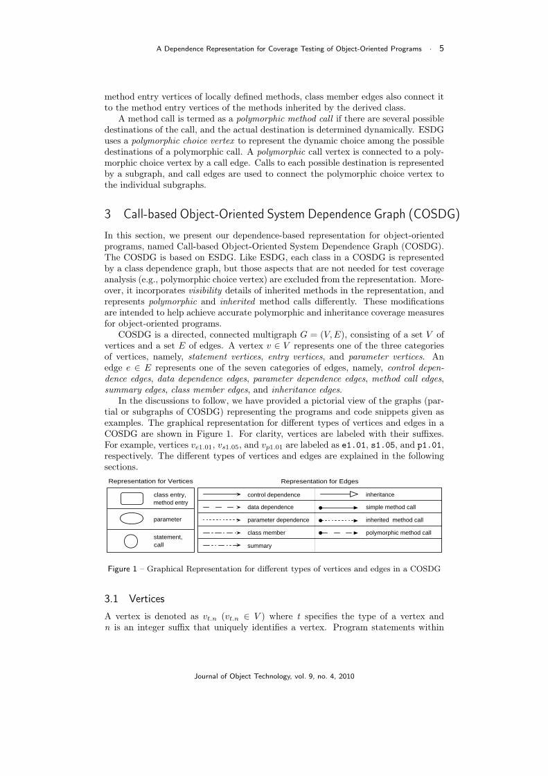
In the discussions to follow, we have provided a pictorial view of the graphs (par-tial or subgraphs of COSDG) representing the programs and code snippets given asexamples. The graphical representation for different types of vertices and edges in aCOSDG are shown in Figure 1. For clarity, vertices are labeled with their suffixes.For example, vertices ve1.01, vs1.05, and vp1.01 are labeled as e1.01, s1.05, and p1.01,respectively. The different types of vertices and edges are explained in the followingsections.
class entry, method entry
parameter
statement, call
control dependence inheritance data dependence simple method call parameter dependence inherited method call class member polymorphic method call summary
Representation for EdgesRepresentation for Vertices
Figure 1 – Graphical Representation for different types of vertices and edges in a COSDG
3.1 Vertices
A vertex is denoted as vt.n (vt.n ∈ V ) where t specifies the type of a vertex andn is an integer suffix that uniquely identifies a vertex. Program statements within
Journal of Object Technology, vol. 9, no. 4, 2010
6 · E.S.F. Najumudheen, Rajib Mall, Debasis Samanta
the body of a method are represented by statement vertices (Vs). These are of twotypes, namely, simple statement vertices and call vertices. Statements that invoke amethod (call sites) are represented by call vertices (Vs2), whereas program statementsother than method calls, such as assignments, loops, and conditions, are representedby simple statement vertices (Vs1). Class and method headers are represented byentry vertices (Ve): class headers by class entry vertices (Ve1), and method headersby method entry vertices (Ve2). Hence, Vs = Vs1 ∪ Vs2, and Ve = Ve1 ∪ Ve2.
COSDG adopts the ESDG’s model for parameter passing between a caller anda callee2. It is modeled by using parameter vertices (Vp) and parameter dependenceedges (Section 2.1). There are four types of parameter vertices, namely, formal-in(Vp1), formal-out (Vp2), actual-in (Vp3), and actual-out (Vp4) vertices. These verticesare similar to the parameter vertices mentioned in Section 2.1.
In the discussions to follow, vs1.n ∈ Vs1, vs2.n ∈ Vs2, ve1.n ∈ Ve1, and ve2.n ∈Ve2 denote a simple statement, a call, a class entry, and a method entry vertex,respectively. Similarly, vp1.n ∈ Vp1, vp2.n ∈ Vp2, vp2.n ∈ Vp3, and vp4.n ∈ Vp4 denote aformal-in, a formal-out, an actual-in, and an actual-out vertex, respectively.
3.2 Edges
An edge is denoted as et.n (et.n ∈ E) where t specifies the type of an edge, and n is aninteger suffix that uniquely identifies an edge. Passing of values between actual andformal parameters is represented by parameter dependence edges (Ep), which are oftwo types: parameter-in (Ep1) and parameter-out (Ep2) edges. Data dependence edges(Ed) represent the flow of data between different statement vertices of the COSDG.These edges are similar to the parameter and data dependence edges described inSection 2.1. Summary edges (Es) represent the transitive flow of dependence betweenactual-in and actual-out vertices.
Thus, ep1.n ∈ Ep1, ep2.n ∈ Ep2, ed.n ∈ Ed, and es.n ∈ Es denote a parameter-in, aparameter-out, a data dependence, and a summary edge, respectively. Other types ofedges are explained in the following subsections.
3.2.1 Class Member Edges
Class member edges (Eb) are used to represent the membership relation between aclass and its methods. They associate all locally defined and overriding methods of aclass with the class entry vertex. A class entry vertex is connected to a method entryvertex by using a class member edge. It is denoted as eb.n where b specifies a classmember edge, and n is an integer suffix that uniquely identifies the edge.
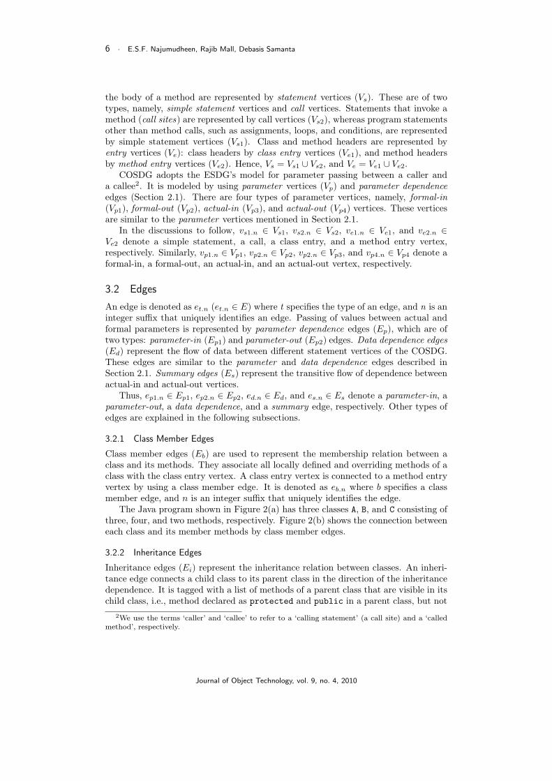
The Java program shown in Figure 2(a) has three classes A, B, and C consisting ofthree, four, and two methods, respectively. Figure 2(b) shows the connection betweeneach class and its member methods by class member edges.
3.2.2 Inheritance Edges
Inheritance edges (Ei) represent the inheritance relation between classes. An inheri-tance edge connects a child class to its parent class in the direction of the inheritancedependence. It is tagged with a list of methods of a parent class that are visible in itschild class, i.e., method declared as protected and public in a parent class, but not
2We use the terms ‘caller’ and ‘callee’ to refer to a ‘calling statement’ (a call site) and a ‘calledmethod’, respectively.
Journal of Object Technology, vol. 9, no. 4, 2010
A Dependence Representation for Coverage Testing of Object-Oriented Programs · 7
01: class A {02: private void m0(){
// base}
03: protected void m1(){// base}
04: public void m2(){// base}
}05: class B extends A {06: public void m2(){
// overriding}
07: private void m3(){// locally defined
}08: public void m4(){
// locally defined}
09: public void m5(){// locally defined}
}10: class C extends B {11: private void m6(){
// locally defined}
12: public void m7(){// locally defined}
}
(a) An example Java program
e1.05
e2. 06 e2.07 e2.08 e2.09
e1.01
e2.02 e2.03 e2.04
e1.10
e2.11 e2.12
(b) Class member edges
e1.05
e1.01
e1.10
ei.02 = { m2 , m4 , m5 }
ei.01 = { m1 }
(c) Inheritance edges with tagsshowing method visibility
Figure 2 – (a) A Java program depicting class membership and inheritance dependences(for clarity, only relevant edges are shown)
overridden in a child class. An inheritance edge is denoted as ei.n where i specifiesan inheritance edge, and n is an integer suffix that uniquely identifies the edge.
Figure 2(c) illustrates the inheritance hierarchy of classes A, B, and C for the Javaprogram in Figure 2(a). In the example, class B is derived from class A, and class Cis derived from class B. Hence, class entry vertex ve1.05 is connected to class entryvertex ve1.01 by an inheritance edge ei.01, and vertex ve1.10 is connected to vertexve1.05 by another inheritance edge ei.02. Out of the three methods defined in class A,m0 is declared as private, m1 as protected, and m2 as public. However, as methodm2 is overridden in the derived class B, only method m1 is visible in class B. Hence,edge ei.01 is tagged with m1 only. Similarly, edge ei.02 is tagged with m2, m4, and m5.
Journal of Object Technology, vol. 9, no. 4, 2010
8 · E.S.F. Najumudheen, Rajib Mall, Debasis Samanta
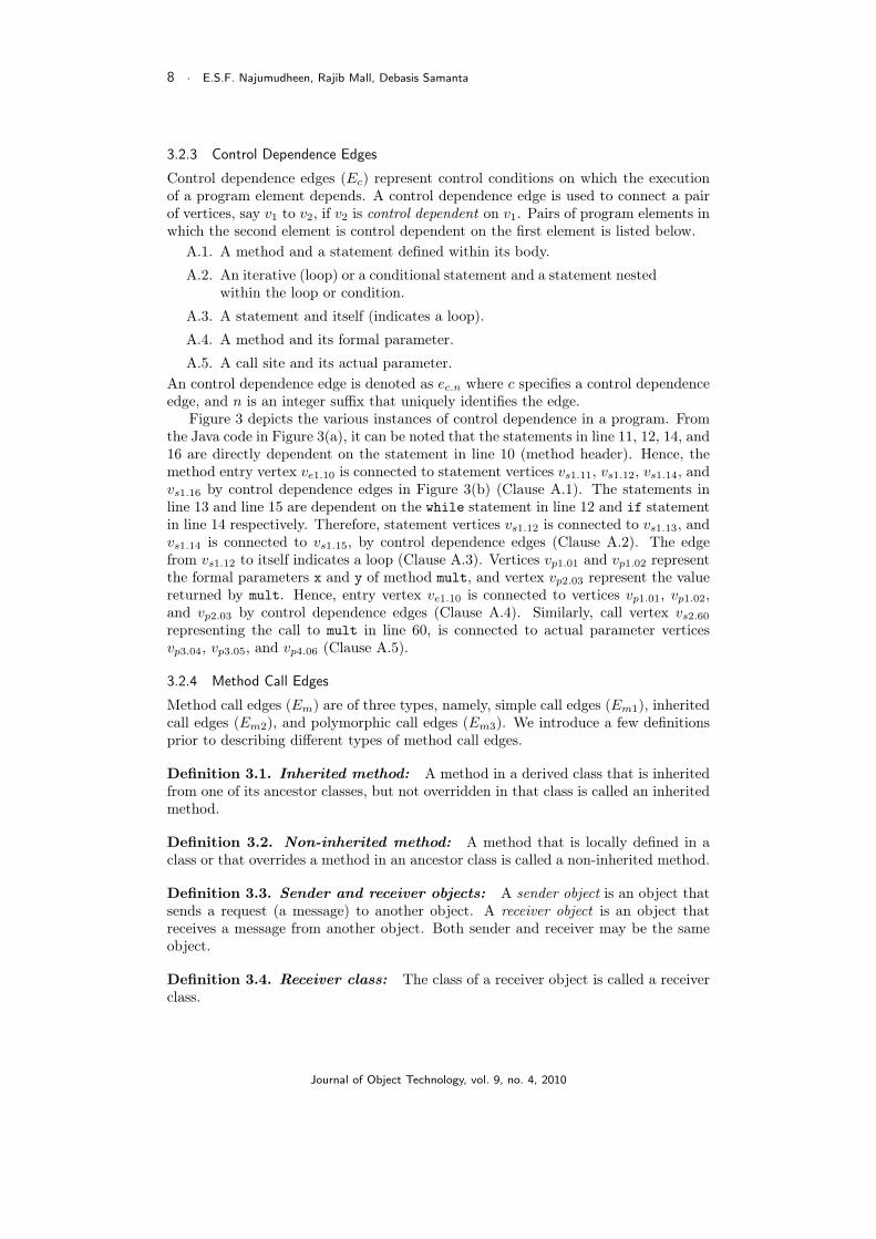
3.2.3 Control Dependence Edges
Control dependence edges (Ec) represent control conditions on which the executionof a program element depends. A control dependence edge is used to connect a pairof vertices, say v1 to v2, if v2 is control dependent on v1. Pairs of program elements inwhich the second element is control dependent on the first element is listed below.
A.1. A method and a statement defined within its body.
A.2. An iterative (loop) or a conditional statement and a statement nestedwithin the loop or condition.
A.3. A statement and itself (indicates a loop).
A.4. A method and its formal parameter.
A.5. A call site and its actual parameter.An control dependence edge is denoted as ec.n where c specifies a control dependenceedge, and n is an integer suffix that uniquely identifies the edge.
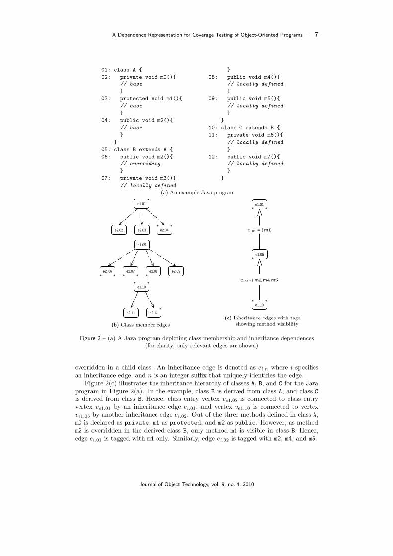
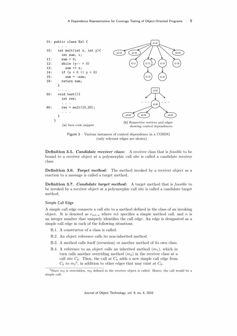
Figure 3 depicts the various instances of control dependence in a program. Fromthe Java code in Figure 3(a), it can be noted that the statements in line 11, 12, 14, and16 are directly dependent on the statement in line 10 (method header). Hence, themethod entry vertex ve1.10 is connected to statement vertices vs1.11, vs1.12, vs1.14, andvs1.16 by control dependence edges in Figure 3(b) (Clause A.1). The statements inline 13 and line 15 are dependent on the while statement in line 12 and if statementin line 14 respectively. Therefore, statement vertices vs1.12 is connected to vs1.13, andvs1.14 is connected to vs1.15, by control dependence edges (Clause A.2). The edgefrom vs1.12 to itself indicates a loop (Clause A.3). Vertices vp1.01 and vp1.02 representthe formal parameters x and y of method mult, and vertex vp2.03 represent the valuereturned by mult. Hence, entry vertex ve1.10 is connected to vertices vp1.01, vp1.02,and vp2.03 by control dependence edges (Clause A.4). Similarly, call vertex vs2.60representing the call to mult in line 60, is connected to actual parameter verticesvp3.04, vp3.05, and vp4.06 (Clause A.5).
3.2.4 Method Call Edges
Method call edges (Em) are of three types, namely, simple call edges (Em1), inheritedcall edges (Em2), and polymorphic call edges (Em3). We introduce a few definitionsprior to describing different types of method call edges.
Definition 3.1. Inherited method: A method in a derived class that is inheritedfrom one of its ancestor classes, but not overridden in that class is called an inheritedmethod.
Definition 3.2. Non-inherited method: A method that is locally defined in aclass or that overrides a method in an ancestor class is called a non-inherited method.
Definition 3.3. Sender and receiver objects: A sender object is an object thatsends a request (a message) to another object. A receiver object is an object thatreceives a message from another object. Both sender and receiver may be the sameobject.
Definition 3.4. Receiver class: The class of a receiver object is called a receiverclass.
Journal of Object Technology, vol. 9, no. 4, 2010
A Dependence Representation for Coverage Testing of Object-Oriented Programs · 9
01: public class Ex1 {. . .
10: int mult(int x, int y){int sum, i;
11: sum = 0;12: while (y-- > 0)13: sum += x;14: if (x < 0 || y < 0)15: sum = -sum;16: return sum;
}. . .
50: void test(){int res;. . .
60: res = mult(10,20);. . .
}}
(a) Java code snippet
s1.14
p2.03p1.02p1.01
s1.12s1.11
e1.10
s1.16
s1.13 s1.15
p4.06p3.05p3.04
. . . . . .
e1.50
s2.60
(b) Respective vertices and edgesshowing control dependences
Figure 3 – Various instances of control dependence in a COSDG(only relevant edges are shown)
Definition 3.5. Candidate receiver class: A receiver class that is feasible to bebound to a receiver object at a polymorphic call site is called a candidate receiverclass.
Definition 3.6. Target method: The method invoked by a receiver object as areaction to a message is called a target method.
Definition 3.7. Candidate target method: A target method that is feasible tobe invoked by a receiver object at a polymorphic call site is called a candidate targetmethod.
Simple Call Edge
A simple call edge connects a call site to a method defined in the class of an invokingobject. It is denoted as em1.n where m1 specifies a simple method call, and n isan integer number that uniquely identifies the call edge. An edge is designated as asimple call edge in each of the following situations.
B.1. A constructor of a class is called.
B.2. An object reference calls its non-inherited method.
B.3. A method calls itself (recursion) or another method of its own class.
B.4. A reference to an object calls an inherited method (m1), which inturn calls another overriding method (m2) in the receiver class at acall site Ck. Then, the call at Ck adds a new simple call edge fromCk to m2
3, in addition to other edges that may exist at Ck.3Since m2 is overridden, m2 defined in the receiver object is called. Hence, the call would be a
simple call.
Journal of Object Technology, vol. 9, no. 4, 2010
10 · E.S.F. Najumudheen, Rajib Mall, Debasis Samanta
Class X in the example Java program shown in Figure 4 depicts the differentinstances of a simple method call. Figure 5(a) illustrates the creation of simple calledges at the respective call sites in method mx.
Call sites c1 and c2 in method mx are calls to constructors B() and C() (ClauseB.1). Therefore, we have simple call edges, em1.01 and em1.02 from vertices vs2.19 andvs2.20 to entry vertices ve2.04 and ve2.13 respectively. The call to method m1 by Obj_Bis a simple call (call site c3) since m1 is a non-inherited method in B (Clause B.2).Hence, call vertex vs2.21 is connected to method entry vertex ve2.05 by a simple calledge em1.03. Method m1 in turn calls method m2 (call site c4). Since m2 is definedlocally in class B, it is a simple call (Clause B.3). Therefore, call vertex vs2.06 isconnected to entry vertex ve2.07 by a simple call edge em1.04. Finally, Obj_C calls m1,a method inherited from its parent B. This call is an inherited method call (discussedin the following section). However, as method m2 is overridden in class C (receiverclass), in the current context, the overriding method m2 is called at call site c4 (ClauseB.4). This call is represented as a simple call edge em1.06 from call vertex vs2.06 tomethod entry vertex ve2.14.
Inherited Call Edge
An inherited call edge connects a call site to a method inherited by the class of aninvoking object. It is denoted as em2.n where m2 specifies an inherited method call,and n is an integer number that uniquely identifies the call edge. An edge is designatedan inherited call edge in each of the following situations.
C.1. An object reference calls its inherited method.
C.2. A method calls a method of its super class.
C.3. A reference to an object calls an inherited method (m1), which inturn calls another inherited method (m2) in the receiver class at callsite Ck. Then, the call at Ck adds a new inherited call edge from Ck
to m2, in addition to other edges that may exist from at Ck.
Class Y in the program shown in Figure 4 depicts the different instances of aninherited method call. Figure 5(b) illustrates the creation of inherited call edges atthe respective call sites in method my.
After the calls to constructors B() and C() (call sites c6 and c7), reference variableInh_B calls method m3 at call site c8. Since m3 is a locally defined method, it is asimple method call. Method m3 in class B calls method m0 in class A (parent class) atcall site c9 (Clause C.2). Therefore, call vertex vs2.09 is connected to method entryvertex ve2.02 by an inherited method call edge em2.10. Next, reference variable Inh_Ccalls an inherited method m4 at call site c10 (Clause C.1). So, call vertex vs2.28 isconnected to entry vertex ve2.10 by an inherited call edge em2.11. Method m4, in turn,calls method m1. As the receiver class is C, in the current context, the call to methodm1 is an inherited method call (Clause C.3). Hence, call vertex vs2.11 is connected toentry vertex ve2.05 by an inheritance call edge em2.12.
Polymorphic Call Edge
A polymorphic call edge connects a call site to a method defined in one of the candidatereceiver classes. It is denoted as em3.n where m3 specifies a polymorphic method call,and n is an integer number that uniquely identifies the call edge. An edge is designatedas a polymorphic call edge in the following situation.
Journal of Object Technology, vol. 9, no. 4, 2010
A Dependence Representation for Coverage Testing of Object-Oriented Programs · 11
D.1. A reference to an object calls a method at a call site Ck. If the targetmethod can not be determined statically, polymorphic call edges areadded at Ck from the caller to the callee, for each candidate targetmethod.
Class Z in the program shown in Figure 4 depicts a polymorphic method call.Figure 5(c) illustrates the creation of polymorphic call edges at the call site. Sincethe reference variable Poly_B at call site c15 in method mz of Class Z can refer toan instance of one of the three classes, B, C, or D, the call to method m2 by Poly_Bis a polymorphic method call. Therefore, polymorphic call edges em3.16, em3.17, andem3.18 are added from the call vertex vs2.37 to the method entry vertices ve2.07, ve2.14,and ve2.14, respectively.
01:class A {02: void m0() {
//base class method}
}
03:class B extends A {04: B() { //constructor }05: void m1() {
//locally defined - 106: m2(); // (c4)
}07: void m2() {
//locally defined - 2}
08: void m3() {09: m0(); // (c9)
}10: void m4() {11: m1(); // (c11)
}}
12:class C extends B {13: C() { //constructor }14: void m2() {
//overriding}
}
15:class D extends C {16: D() { //constructor }
//inherited}
17:class X {18: void mx() {19: B Obj_B = new B(); // simple (c1)20: C Obj_C = new C(); // simple (c2)21: Obj_B.m1(); // simple (c3)22: Obj_C.m1(); // inherited (c5)
}}
23:class Y {24: void my() {25: B Inh_B = new B(); // (c6)26: C Inh_C = new C(); // (c7)27: Inh_B.m3(); // simple (c8)28: Inh_C.m4(); // inherited (c10)
}}
29:class Z {30: void mz() {31: int x;
. . .32: B Poly_B = new B(); // (c12)33: if (x == 10)34: Poly_B = new C(); // (c13)
else35: if (x == 20)36: Poly_B = new D(); // (c14)37: Poly_B.m2(); //polymorphic (c15)
. . .}
}
Figure 4 – An example Java program depicting different types of method calls
Journal of Object Technology, vol. 9, no. 4, 2010

12 · E.S.F. Najumudheen, Rajib Mall, Debasis Samanta
s2.21s2.20s2.19
e2.18
e1.17
s2.22
e2.05
e1.03
e2.13
e1.12
e2.07
e m1.01e m1.02
e2.04e2.14
e m1.03 e m2.05
s2.06
e m1.04e m1.06
(a) Method call edges in method mx
s2.27s2.26s2.25
e2.24
e1.23
s2.28
e2.08
e1.03
e2.13
e1.12
e2.05
e m1.07e m1.08
e2.04
e m1.09 e m2.11
s2.09
e m2.10
e1.01
e2.02e2.10
e m2.12s2.11
(b) Method call edges in method my
simple call inherited call polymorphic call
s2.36
s2.34
s2.32
e2.30
e1.29
s2.37
e1.03
e2.13
e1.12
e2.07
e m1.13e m1.14
e2.04 e2.14
e m1.15e m3.16
e2.16
e1.15
e m3.18e m3.17
s1.33
s1.35
(c) Method call edges in method mz
Figure 5 – Edges illustrating various types of method calls in the program shown inFigure 4 (only relevant vertices and edges are shown)
4 Construction of a COSDG
In this section, we discuss the construction of the COSDG representation of a program.We first outline the various steps in constructing the CODSG for a complete program.First, the class dependence graph for each class is constructed. Next, the inheritancehierarchy is established among classes by connecting the parent and child classes withinheritance edges. Finally, algorithm BuildCallSite processes the call sites in each
Journal of Object Technology, vol. 9, no. 4, 2010

A Dependence Representation for Coverage Testing of Object-Oriented Programs · 13
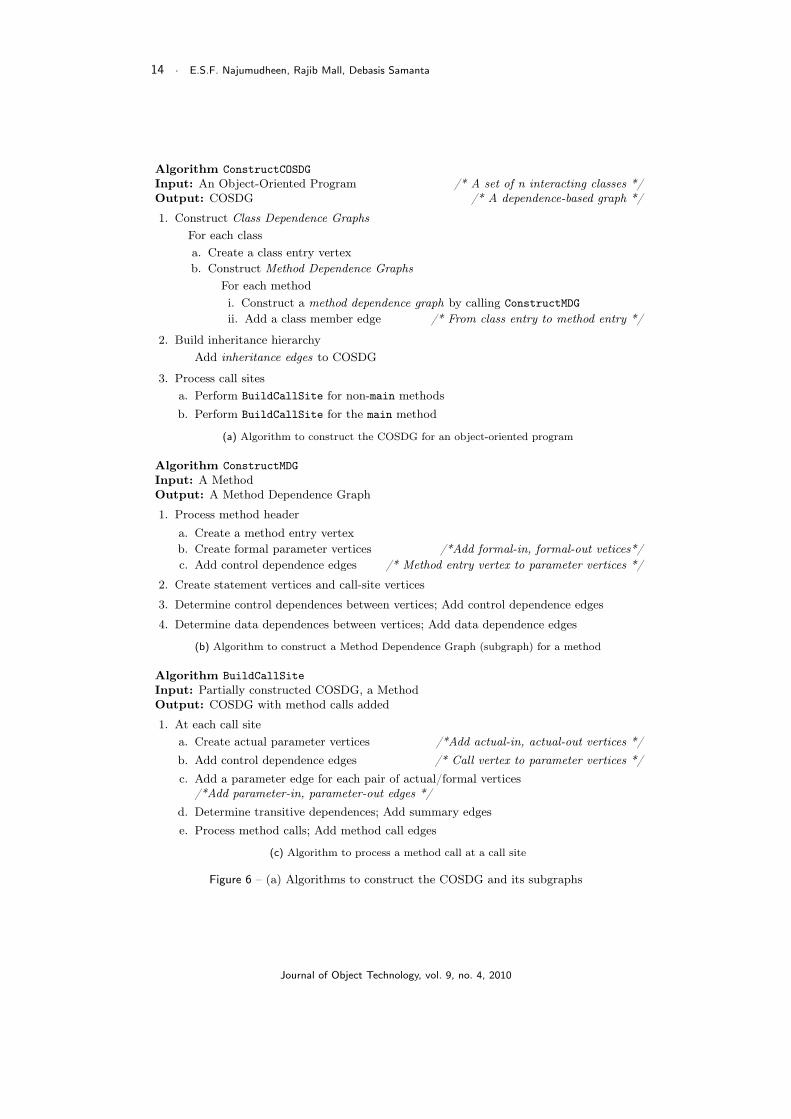
method to establish a connection between a call site and a callee, which results ina connected multigraph. This is done in two stages. First, call-sites in all the non-main4 methods are processed to build clusters. Next, call sites in the main method areprocessed to establish a connection between the class that contains the main methodand the classes within each cluster. Thus, it builds a call graph for the completeprogram by incrementally adding method call edges at the call sites. These steps havebeen presented in pseudo-code form in Figure 6(a) (Algorithm ConstructCOSDG).
The pseudo code for algorithm ConstructMDG is shown in Figure 6(b). It outlinesthe different steps in constructing the method dependence graph for a method defi-nition. First, the method header is processed and a method entry vertex is created.Subsequently, formal-in and formal-out parameter vertices are created. The parame-ter vertices are connected to the method entry vertex with control dependence edges.Next, the statements within the method definition are processed, and correspondingstatement and call-site vertices are created. Then, after performing control depen-dence and data dependence analyses, control dependence and data dependence edgesare added.
Algorithm BuildCallSite shown in Figure 6(c) outlines the different steps in pro-cessing a method call statement (call site). First, actual-in and actual-out parametervertices are created at each call site. The parameter vertices are connected to thecorresponding call vertex with control dependence edges. Next, data flow between acall site and its callee is established by adding parameter edges between actual andformal vertices. Then, summary edges are added to indicate transitive dependenciesbetween actual-in and actual-out parameter vertices. Finally, various method calledges are added (described in Section 3.2.4).
Example
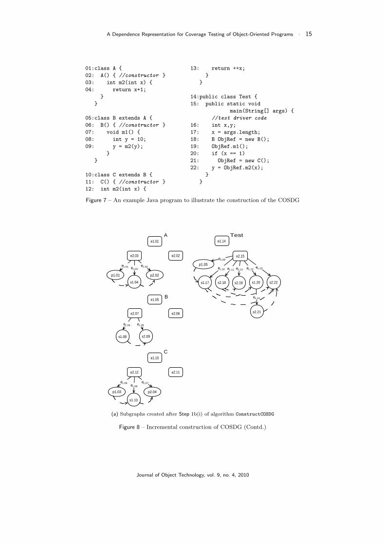
We now illustrate the construction of the COSDG with the help of an example Javaprogram shown in Figure 75. Class A is the base class. Class B is derived from class A,C is derived from B, and D is derived from C. The main method in class Test containsthe test driver code.
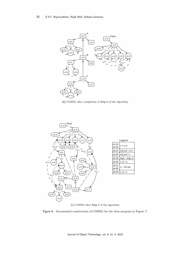
The class dependence graph for each class is created in three steps. First, theclass entry vertex for a class is created (Step 1a). In Step 1b(i), ConstructCOSDGcalls ConstructMDG to construct the method dependence graphs for the methods ofeach class in the program. Then, the method dependence graphs are associated withthe class entry vertex by adding class member edges (Step 1b(ii)). Figure 8(a) illus-trates the creation of class entry vertices and the construction of method dependencegraphs. In Step 2, ConstructCOSDG establishes the inheritance hierarchy. Figure 8(b)illustrates the addition of class member edges, and the construction of the inheritancetree. In Step 3, the algorithm invokes BuildCallSite to process the call sites. Forsimple method calls, a simple call edge is added from the call vertex to the methodentry vertex of the callee. For polymorphic calls, a polymorphic call edge is addedfrom the call vertex to the method entry vertices of each target method. Method callsfrom various call sites to their respective method entry vertices are shown in Figure8(c). It shows the final form of the COSDG for the Java program given in Figure 7.To avoid cluttering, only some of the data dependence edges have been shown in thefigure. Also, parameter and summary edges have not been shown in the figure.
4Here, we assume that the main method represents the test driver code that would test the variousfeatures of classes.
5A detailed description of the working of the algorithm ConstructCOSDG is available in [14].
Journal of Object Technology, vol. 9, no. 4, 2010
14 · E.S.F. Najumudheen, Rajib Mall, Debasis Samanta
Algorithm ConstructCOSDGInput: An Object-Oriented Program /* A set of n interacting classes */Output: COSDG /* A dependence-based graph */
1. Construct Class Dependence GraphsFor each classa. Create a class entry vertexb. Construct Method Dependence Graphs
For each methodi. Construct a method dependence graph by calling ConstructMDGii. Add a class member edge /* From class entry to method entry */
2. Build inheritance hierarchyAdd inheritance edges to COSDG
3. Process call sitesa. Perform BuildCallSite for non-main methodsb. Perform BuildCallSite for the main method
(a) Algorithm to construct the COSDG for an object-oriented program
Algorithm ConstructMDGInput: A MethodOutput: A Method Dependence Graph
1. Process method headera. Create a method entry vertexb. Create formal parameter vertices /*Add formal-in, formal-out vetices*/c. Add control dependence edges /* Method entry vertex to parameter vertices */
2. Create statement vertices and call-site vertices
3. Determine control dependences between vertices; Add control dependence edges
4. Determine data dependences between vertices; Add data dependence edges
(b) Algorithm to construct a Method Dependence Graph (subgraph) for a method
Algorithm BuildCallSiteInput: Partially constructed COSDG, a MethodOutput: COSDG with method calls added
1. At each call sitea. Create actual parameter vertices /*Add actual-in, actual-out vertices */b. Add control dependence edges /* Call vertex to parameter vertices */c. Add a parameter edge for each pair of actual/formal vertices
/*Add parameter-in, parameter-out edges */d. Determine transitive dependences; Add summary edgese. Process method calls; Add method call edges
(c) Algorithm to process a method call at a call site
Figure 6 – (a) Algorithms to construct the COSDG and its subgraphs
Journal of Object Technology, vol. 9, no. 4, 2010
A Dependence Representation for Coverage Testing of Object-Oriented Programs · 15
01:class A {02: A() { //constructor }03: int m2(int x) {04: return x+1;
}}
05:class B extends A {06: B() { //constructor }07: void m1() {08: int y = 10;09: y = m2(y);
}}
10:class C extends B {11: C() { //constructor }12: int m2(int x) {
13: return ++x;}
}
14:public class Test {15: public static void
main(String[] args) {//test driver code
16: int x,y;17: x = args.length;18: B ObjRef = new B();19: ObjRef.m1();20: if (x == 1)21: ObjRef = new C();22: y = ObjRef.m2(x);
}}
Figure 7 – An example Java program to illustrate the construction of the COSDG
ec.05ec.04
s1.04
ec.03ec.02
p2.02
e2.07
e2.03
s1.08 s2.09
ec.15
ec.09
p1.05
ec.14
ec.13ec.12
e2.15
s2.18 s2.22
s2.21
s1.20s1.17 s2.19
ec.11ec.10
p1.01
ec.01
s1.13
ec.08ec.07
p2.04
e2.12
p1.03
ec.06
e2.02
e2.06
e2.11
A
B
C
Teste1.01
e1.05
e1.10
e1.14
(a) Subgraphs created after Step 1b(i) of algorithm ConstructCOSDG
Figure 8 – Incremental construction of COSDG (Contd.)
Journal of Object Technology, vol. 9, no. 4, 2010
16 · E.S.F. Najumudheen, Rajib Mall, Debasis Samanta
ec.05ec.04
s1.04
ec.03ec.02
p2.02
e2.07
e2.03
s1.08 s2.09
p1.01
ec.01
s1.13
ec.08ec.07
p2.04
e2.12
p1.03
ec.06
e2.02
e2.06
e2.11
A
B
C
e1.01
e1.05
e1.10
ec.15
ec.09
p1.05
ec.14
ec.13ec.12
e2.15
s2.18 s2.22
s2.21
s1.20s1.17 s2.19
ec.11ec.10
Teste1.14
(b) COSDG after completion of Step 2 of the algorithm
ec.13
ec.09
p1.05
ec.14
ec.10ec.11
e2.15
s2.22 s2.20
s2.21
s1.17s2.19 s2.18
ec.15ec.12
e1.01 e1.05
e1.10
e1.14Test
ec.04 ec.05
s1.04
ec.03
ec.02
p2.02
e2.07
e2.03
s2.09
s1.08
p1.01
ec.01
s1.13 ec.08
ec.07
p2.04
e2.12
p1.03
ec.06
p3.06em2.01
e2.02
e2.06
em1.02
em1.03
e1..11
em1.04
em3.05
p4.07
em3.06
p3.08 p4.09p1.01,p1.03 x = x_in
p2.02 m2_out = x+1p2.04 m2_out = xp1.05 args = args_inp3.06 x_in = yp4.07,p4.09 y = m2.out
p3.08 x_in = x
Legend
(c) COSDG after Step 3 of the algorithm
Figure 8 – Incremental construction of COSDG for the Java program in Figure 7.
Journal of Object Technology, vol. 9, no. 4, 2010
A Dependence Representation for Coverage Testing of Object-Oriented Programs · 17
5 Test Coverage Analysis using COSDG
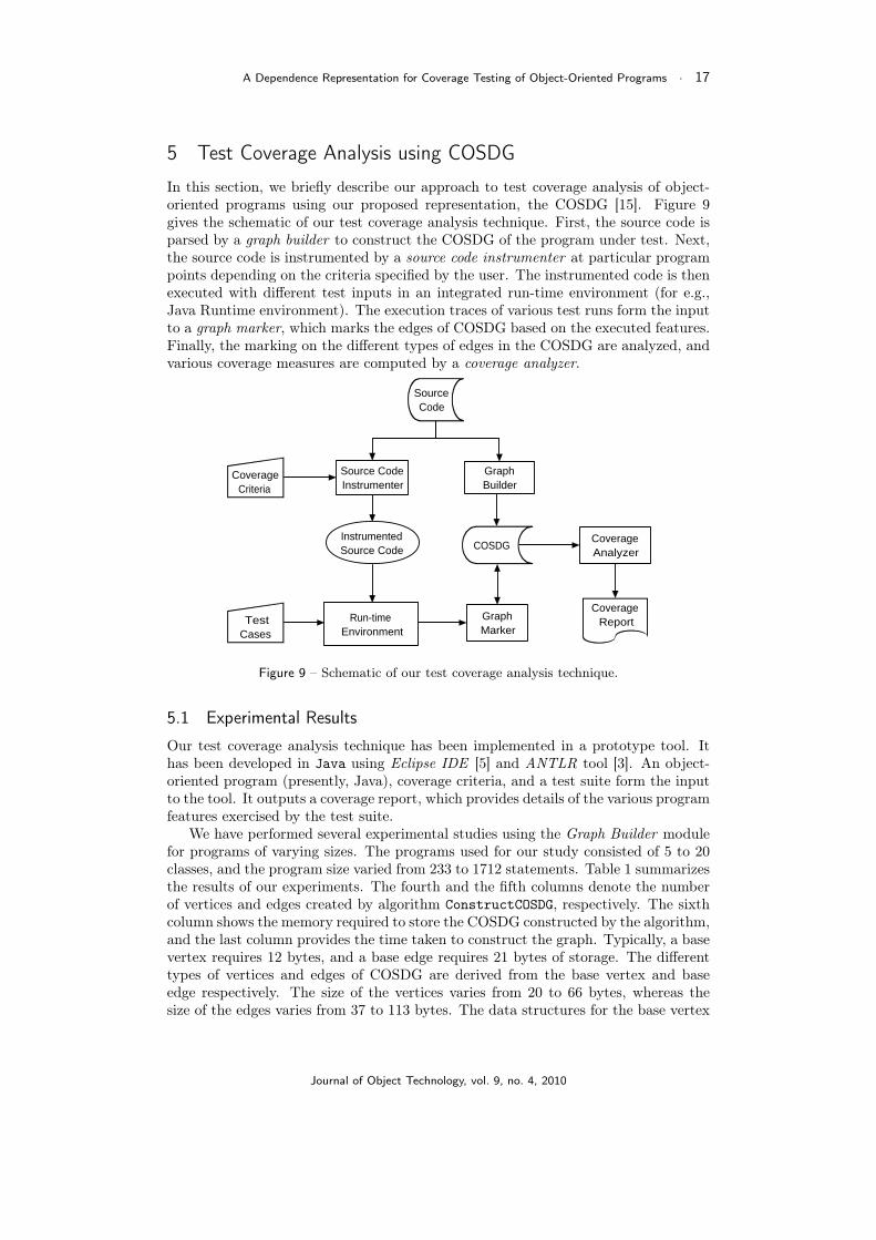
In this section, we briefly describe our approach to test coverage analysis of object-oriented programs using our proposed representation, the COSDG [15]. Figure 9gives the schematic of our test coverage analysis technique. First, the source code isparsed by a graph builder to construct the COSDG of the program under test. Next,the source code is instrumented by a source code instrumenter at particular programpoints depending on the criteria specified by the user. The instrumented code is thenexecuted with different test inputs in an integrated run-time environment (for e.g.,Java Runtime environment). The execution traces of various test runs form the inputto a graph marker, which marks the edges of COSDG based on the executed features.Finally, the marking on the different types of edges in the COSDG are analyzed, andvarious coverage measures are computed by a coverage analyzer.
Run-timeEnvironment
Source CodeInstrumenter
CoverageAnalyzer
CoverageReport
InstrumentedSource Code
SourceCode
GraphBuilder
GraphMarker
TestCases
COSDG
CoverageCriteria
Figure 9 – Schematic of our test coverage analysis technique.
5.1 Experimental Results
Our test coverage analysis technique has been implemented in a prototype tool. Ithas been developed in Java using Eclipse IDE [5] and ANTLR tool [3]. An object-oriented program (presently, Java), coverage criteria, and a test suite form the inputto the tool. It outputs a coverage report, which provides details of the various programfeatures exercised by the test suite.
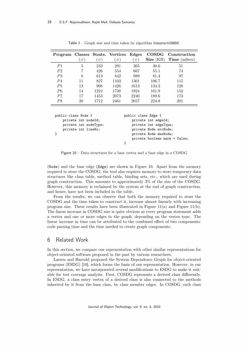
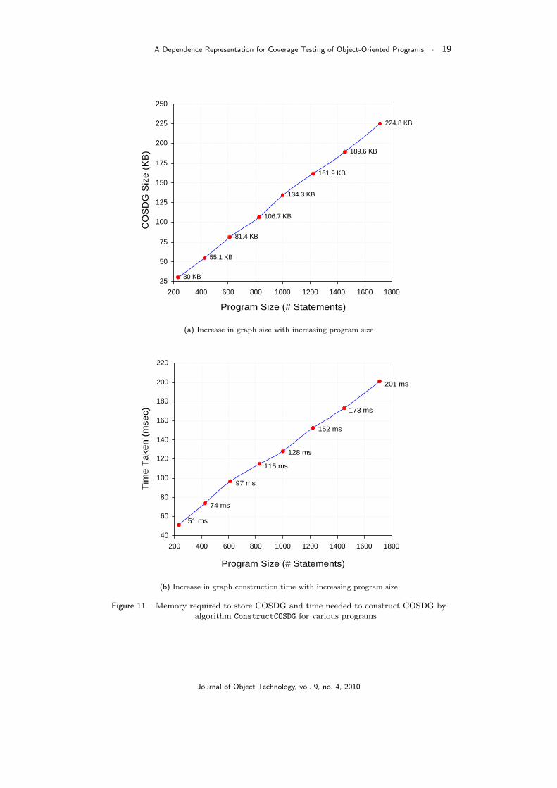
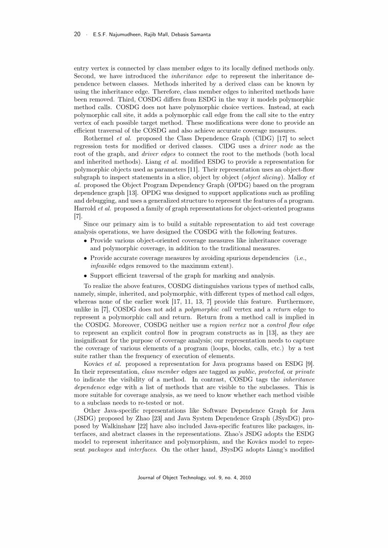
We have performed several experimental studies using the Graph Builder modulefor programs of varying sizes. The programs used for our study consisted of 5 to 20classes, and the program size varied from 233 to 1712 statements. Table 1 summarizesthe results of our experiments. The fourth and the fifth columns denote the numberof vertices and edges created by algorithm ConstructCOSDG, respectively. The sixthcolumn shows the memory required to store the COSDG constructed by the algorithm,and the last column provides the time taken to construct the graph. Typically, a basevertex requires 12 bytes, and a base edge requires 21 bytes of storage. The differenttypes of vertices and edges of COSDG are derived from the base vertex and baseedge respectively. The size of the vertices varies from 20 to 66 bytes, whereas thesize of the edges varies from 37 to 113 bytes. The data structures for the base vertex
Journal of Object Technology, vol. 9, no. 4, 2010
18 · E.S.F. Najumudheen, Rajib Mall, Debasis Samanta
Table 1 – Graph size and time taken by algorithm ConsructCOSDG
Program Classes Stmts. Vertices Edges COSDG Construction(#) (#) (#) (#) Size (KB) Time (mSecs)
P1 5 233 291 365 30.0 51P2 7 426 554 667 55.1 74P3 8 613 842 989 81.4 97P4 11 827 1103 1301 106.7 115P5 13 998 1426 1613 134.3 128P6 14 1224 1738 1924 161.9 152P7 17 1453 2073 2240 189.6 173P8 20 1712 2461 2657 224.8 201
public class Node {private int nodeId;private int nodeType;private int lineNo;
}
public class Edge {private int edgeId;private int edgeType;private Node srcNode;private Node desNode;private boolean mark = false;
}
Figure 10 – Data structures for a base vertex and a base edge in a COSDG
(Node) and the base edge (Edge) are shown in Figure 10. Apart from the memoryrequired to store the COSDG, the tool also requires memory to store temporary datastructures like class table, method table, binding sets, etc., which are used duringgraph construction. This amounts to approximately 3% of the size of the COSDG.However, this memory is reclaimed by the system at the end of graph construction,and hence, have not been included in the table.
From the results, we can observe that both the memory required to store theCOSDG and the time taken to construct it, increase almost linearly with increasingprogram size. These results have been illustrated in Figure 11(a) and Figure 11(b).The linear increase in COSDG size is quite obvious as every program statement addsa vertex and one or more edges to the graph, depending on the vertex type. Thelinear increase in time can be attributed to the combined effect of two components:code parsing time and the time needed to create graph components.
6 Related Work
In this section, we compare our representation with other similar representations forobject-oriented software proposed in the past by various researchers.
Larsen and Harrold proposed the System Dependence Graph for object-orientedprograms (ESDG) [10], which forms the basis of our representation. However, in ourrepresentation, we have incorporated several modifications to ESDG to make it suit-able for test coverage analysis. First, COSDG represents a derived class differently.In ESDG, a class entry vertex of a derived class is also connected to the methodsinherited by it from the base class, by class member edges. In COSDG, each class
Journal of Object Technology, vol. 9, no. 4, 2010
A Dependence Representation for Coverage Testing of Object-Oriented Programs · 19
224.8 KB
189.6 KB
161.9 KB
134.3 KB
106.7 KB
81.4 KB
55.1 KB
30 KB25
50
75
100
125
150
175
200
225
250
200 400 600 800 1000 1200 1400 1600 1800
Program Size (# Statements)
CO
SD
G S
ize
(KB
)
(a) Increase in graph size with increasing program size
51 ms
74 ms
97 ms
115 ms
128 ms
152 ms
173 ms
201 ms
40
60
80
100
120
140
160
180
200
220
200 400 600 800 1000 1200 1400 1600 1800
Program Size (# Statements)
Tim
e T
aken
(m
sec)
(b) Increase in graph construction time with increasing program size
Figure 11 – Memory required to store COSDG and time needed to construct COSDG byalgorithm ConstructCOSDG for various programs
Journal of Object Technology, vol. 9, no. 4, 2010
20 · E.S.F. Najumudheen, Rajib Mall, Debasis Samanta
entry vertex is connected by class member edges to its locally defined methods only.Second, we have introduced the inheritance edge to represent the inheritance de-pendence between classes. Methods inherited by a derived class can be known byusing the inheritance edge. Therefore, class member edges to inherited methods havebeen removed. Third, COSDG differs from ESDG in the way it models polymorphicmethod calls. COSDG does not have polymorphic choice vertices. Instead, at eachpolymorphic call site, it adds a polymorphic call edge from the call site to the entryvertex of each possible target method. These modifications were done to provide anefficient traversal of the COSDG and also achieve accurate coverage measures.
Rothermel et al. proposed the Class Dependence Graph (ClDG) [17] to selectregression tests for modified or derived classes. ClDG uses a driver node as theroot of the graph, and driver edges to connect the root to the methods (both localand inherited methods). Liang et al. modified ESDG to provide a representation forpolymorphic objects used as parameters [11]. Their representation uses an object-flowsubgraph to inspect statements in a slice, object by object (object slicing). Malloy etal. proposed the Object Program Dependency Graph (OPDG) based on the programdependence graph [13]. OPDG was designed to support applications such as profilingand debugging, and uses a generalized structure to represent the features of a program.Harrold et al. proposed a family of graph representations for object-oriented programs[7].
Since our primary aim is to build a suitable representation to aid test coverageanalysis operations, we have designed the COSDG with the following features.• Provide various object-oriented coverage measures like inheritance coverage
and polymorphic coverage, in addition to the traditional measures.• Provide accurate coverage measures by avoiding spurious dependencies (i.e.,infeasible edges removed to the maximum extent).
• Support efficient traversal of the graph for marking and analysis.
To realize the above features, COSDG distinguishes various types of method calls,namely, simple, inherited, and polymorphic, with different types of method call edges,whereas none of the earlier work [17, 11, 13, 7] provide this feature. Furthermore,unlike in [7], COSDG does not add a polymorphic call vertex and a return edge torepresent a polymorphic call and return. Return from a method call is implied inthe COSDG. Moreover, COSDG neither use a region vertex nor a control flow edgeto represent an explicit control flow in program constructs as in [13], as they areinsignificant for the purpose of coverage analysis; our representation needs to capturethe coverage of various elements of a program (loops, blocks, calls, etc.) by a testsuite rather than the frequency of execution of elements.
Kovács et al. proposed a representation for Java programs based on ESDG [9].In their representation, class member edges are tagged as public, protected, or privateto indicate the visibility of a method. In contrast, COSDG tags the inheritancedependence edge with a list of methods that are visible to the subclasses. This ismore suitable for coverage analysis, as we need to know whether each method visibleto a subclass needs to re-tested or not.
Other Java-specific representations like Software Dependence Graph for Java(JSDG) proposed by Zhao [23] and Java System Dependence Graph (JSysDG) pro-posed by Walkinshaw [22] have also included Java-specific features like packages, in-terfaces, and abstract classes in the representations. Zhao’s JSDG adopts the ESDGmodel to represent inheritance and polymorphism, and the Kovács model to repre-sent packages and interfaces. On the other hand, JSysDG adopts Liang’s modified
Journal of Object Technology, vol. 9, no. 4, 2010
A Dependence Representation for Coverage Testing of Object-Oriented Programs · 21
ESDG model to represent polymorphic objects, and Kovács model to represent thevisibility of methods in a class. In addition, JSysDG differentiates between normaland abstract methods by using abstract method edges.
7 Conclusions
We have proposed a dependence-based representation for object-oriented programs,named Call-based Object-Oriented System Dependence Graph (COSDG), for use asan internal representation for performing test coverage analysis. Apart from repre-senting basic features like control flow, data flow, and method calls, COSDG capturesobject-oriented features such as class, inheritance, and polymorphism. Novel fea-tures of COSDG include details of method visibility in a derived class, and differenttypes of method call edges to depict different calling contexts: simple, inherited, andpolymorphic method calls.
Test coverage techniques can be applied to COSDG to obtain the necessary object-oriented coverage measures. A prototype tool has been developed in Java for testcoverage analysis of object-oriented programs using the COSDG. We have conductedexperimental studies to ascertain the efficacy of COSDG in testing object-orientedprograms. Results from our study show that both space and time required to constructthe COSDG is linear in program size.
The present version of COSDG represents only the basic object-oriented features.We are extending our representation to include exception handling features.
References
[1] Hira Agrawal. Efficient coverage testing using global dominator graphs. InProc. of the 1999 ACM SIGPLAN-SIGSOFT Workshop on Program Analysisfor Software Tools and Engg. (PASTE ’99), pages 11–20, Toulouse, France, Sep1999.
[2] Frances E. Allen. Control flow analysis. ACM SIGPLAN Notices, 5(7):1–19,Jul 1970. Proc. of a Symposium on Compiler Optimization.
[3] ANTLR. ANother Tool for Language Recognition. http://www.antlr.org/.Date Accessed: 31 Sep. 2009.
[4] Peter J. Clarke and Brian A. Malloy. A taxonomy of OO classes to supportthe mapping of testing techniques to a class. Journal of Object Technology,4(5):95–115, Jul-Aug 2005.
[5] Eclipse. http://www.eclipse.org/. Date Accessed: 31 Sep. 2009.[6] Jeanne Ferrante, Karl J. Ottenstein, and Joe D. Warren. The program depen-
dence graph and its use in optimization. ACM Transactions on ProgrammingLanguages and Systems, 9(3):319–349, Jul 1987.
[7] Mary Jean Harrold and Greg Rothermel. A coherent family of analyzablegraphical representations for object-oriented software. Tech. Report OSU-CISRC-11/96-TR60, Department of Computer and Information Science, TheOhio State University, Nov 1996.
[8] Susan Horwitz, Thomas Reps, and David Binkley. Interprocedural slicing us-ing dependence graphs. ACM Transactions on Programming Languages andSystems, 12(1):26–60, Jan 1990.
Journal of Object Technology, vol. 9, no. 4, 2010
22 · E.S.F. Najumudheen, Rajib Mall, Debasis Samanta
[9] Gyula Kovács, Ferenc Magyar, and Tibor Gyimóthy. Static slicing of Java pro-grams. Tech. Report TR-96-108, Research Group on Artificial Intelligence,Hungarian Academy of Sciences, József Attila University, Hungary, Dec 1996.
[10] Loren Larsen and Mary Jean Harrold. Slicing object-oriented software. InProc. of the 18th International Conference on Software Engineering, pages495–505, Berlin, Germany, Mar 1996.
[11] Donglin Liang and Mary Jean Harrold. Slicing objects using system depen-dence graphs. In Proc. of the IEEE Intl. Conf. of Software Maintenance (ICSM’98), pages 358–367, Bethesda, MD, USA, Nov 1998.
[12] Raghu Lingampally, Atul Gupta, and Pankaj Jalote. A multipurpose code cov-erage tool for Java. In Proc. of the 40th Annual Hawaii Intl. Conf. on SystemSciences (HICSS ’07), pages 261b – 271b, Jan 2007.
[13] Brian A. Malloy, John D. McGregor, Anand Krishnaswamy, and MuraliMedikonda. An extensible program representation for object-oriented software.ACM SIGPLAN Notices, 29(12):38–47, Dec 1994.
[14] E S F Najumudheen. An intermediate representation for test coverage analysisof object-oriented programs. Tech. Report IITKGP-CSE-TR-17/2008, IndianInstitute of Technology, Kharagpur, India, Jan 2008.
[15] E S F Najumudheen, Rajib Mall, and Debasis Samanta. A dependence graph-based test coverage analysis technique for object-oriented programs. In Proc.of the 6th Intl. Conf. on Info. Technology: New Generations (ITNG ’09), pages763–768, Las Vegas, NV, USA, Apr 2009.
[16] Karl J. Ottenstein. Data-Flow Graphs as an Intermediate Program Form. PhDthesis, Computer Sciences Dept., Purdue Univ., Lafayette, IN, Aug 1978.
[17] Gregg Rothermel and Mary Jean Harrold. Selecting regression tests for object-oriented software. In Proc. of the Intl. Conf. on Software Maintenance - 1994,pages 14–25, Victoria, BC, Canada, Sep 1994.
[18] Atanas Rountev, Scott Kagan, and Michael Gibas. Static and dynamic anal-ysis of call chains in Java. In Proc. of the 2004 ACM SIGSOFT InternationalSymposium on Software Testing and Analysis (ISSTA ’04), pages 1–11, Boston,MA, USA, Jul 2004, Vol. 29 No. 4.
[19] Atanas Rountev, Ana Milanova, and Barbara G. Ryder. Fragment class anal-ysis for testing of polymorphism in Java software. IEEE Transactions on Soft-ware Engineering, 30(6):372–387, Jun 2004.
[20] Barbara G. Ryder. Constructing the call graph of a program. IEEE Transac-tions on Software Engineering, SE-5(3):216–226, May 1979.
[21] A.M.R. Vincenzi, J.C. Maldonado, W.E. Wong, and M.E. Delamaro. Coveragetesting of Java programs and components. Science of Computer Programming,56(1-2):211–230, Apr 2005.
[22] Neil Walkinshaw, Marc Roper, and Murray Wood. The Java system depen-dence graph. In Proc. of the Third IEEE Intl. Workshop on Source Code Anal-ysis and Manipulation, (SCAM ’03), pages 55–64, Amsterdam, The Nether-lands, Sep 2003.
[23] Jianjun Zhao. Applying program dependence analysis to Java software. InProc. of Workshop on Software Engineering and Database Systems, 1998 Inter-national Computer Symposium, pages 162–169, Tainan, Taiwan, Dec 1998.
Journal of Object Technology, vol. 9, no. 4, 2010
A Dependence Representation for Coverage Testing of Object-Oriented Programs · 23
About the authors
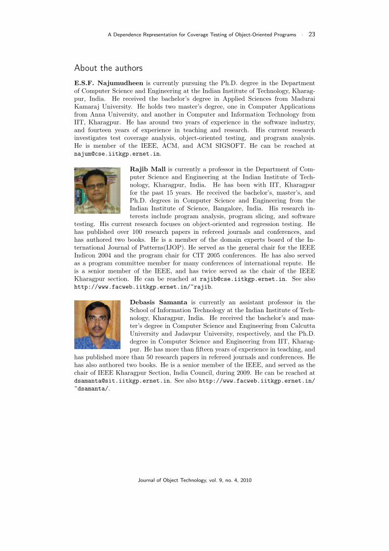
E.S.F. Najumudheen is currently pursuing the Ph.D. degree in the Departmentof Computer Science and Engineering at the Indian Institute of Technology, Kharag-pur, India. He received the bachelor’s degree in Applied Sciences from MaduraiKamaraj University. He holds two master’s degree, one in Computer Applicationsfrom Anna University, and another in Computer and Information Technology fromIIT, Kharagpur. He has around two years of experience in the software industry,and fourteen years of experience in teaching and research. His current researchinvestigates test coverage analysis, object-oriented testing, and program analysis.He is member of the IEEE, ACM, and ACM SIGSOFT. He can be reached [email protected].
Rajib Mall is currently a professor in the Department of Com-puter Science and Engineering at the Indian Institute of Tech-nology, Kharagpur, India. He has been with IIT, Kharagpurfor the past 15 years. He received the bachelor’s, master’s, andPh.D. degrees in Computer Science and Engineering from theIndian Institute of Science, Bangalore, India. His research in-terests include program analysis, program slicing, and software
testing. His current research focuses on object-oriented and regression testing. Hehas published over 100 research papers in refereed journals and conferences, andhas authored two books. He is a member of the domain experts board of the In-ternational Journal of Patterns(IJOP). He served as the general chair for the IEEEIndicon 2004 and the program chair for CIT 2005 conferences. He has also servedas a program committee member for many conferences of international repute. Heis a senior member of the IEEE, and has twice served as the chair of the IEEEKharagpur section. He can be reached at [email protected]. See alsohttp://www.facweb.iitkgp.ernet.in/~rajib.
Debasis Samanta is currently an assistant professor in theSchool of Information Technology at the Indian Institute of Tech-nology, Kharagpur, India. He received the bachelor’s and mas-ter’s degree in Computer Science and Engineering from CalcuttaUniversity and Jadavpur University, respectively, and the Ph.D.degree in Computer Science and Engineering from IIT, Kharag-pur. He has more than fifteen years of experience in teaching, and
has published more than 50 research papers in refereed journals and conferences. Hehas also authored two books. He is a senior member of the IEEE, and served as thechair of IEEE Kharagpur Section, India Council, during 2009. He can be reached [email protected]. See also http://www.facweb.iitkgp.ernet.in/~dsamanta/.
Journal of Object Technology, vol. 9, no. 4, 2010