9500mpr networking ed02it05
DESCRIPTION
Alcatel MPRTRANSCRIPT

9500 MPR TMN Networking
3EM237181306BVZZA02it05 Draft
August, 2011
2 3EM 23718 1306 BVZZA Ed02it05 9500 MPR TMN Networking
S. WinslowAll Rights Reserved © Alcatel-Lucent 2011
9500MPR TMN Networking
Sections in this Presentation
1) TMN Interfaces
2) TMN Related Services
3) TMN IP Addresses
4) The TMN Network
5) Basic MPR Address Provisioning
6) Interconnecting Multiple MPR Shelves
7) Craft and Management Communication Requirements
8) Planning and Addressing a Network
9) Configuring the MPR
------------------------------------
A. Basics of IP Addressing
B. Communication in Networks
C. MPR DHCP Overview
D. MPR OSPF Overview
E. Comparison to TMN Networking in the MDR-8000
F. MPR-e and MPR-1c differences
G. Default and Reserved addresses
3 3EM 23718 1306 BVZZA Ed02it05 9500 MPR TMN Networking
S. WinslowAll Rights Reserved © Alcatel-Lucent 2011
19500MPR TMN Networking
TMN Interfaces
4 3EM 23718 1306 BVZZA Ed02it05 9500 MPR TMN Networking
S. WinslowAll Rights Reserved © Alcatel-Lucent 2011
9500MPR TMN Networking
Physical Interfaces
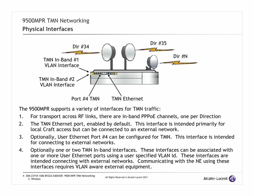
The 9500MPR supports a variety of interfaces for TMN traffic:
1. For transport across RF links, there are in-band PPPoE channels, one per Direction
2. The TMN Ethernet port, enabled by default. This interface is intended primarily for local Craft access but can be connected to an external network.
3. Optionally, User Ethernet Port #4 can be configured for TMN. This interface is intended for connecting to external networks.
4. Optionally one or two TMN In-band interfaces. These interfaces can be associated with one or more User Ethernet ports using a user specified VLAN Id. These interfaces are intended connecting with external networks. Communicating with the NE using these interfaces requires VLAN aware external equipment.
Dir #34Dir #35
Port #4 TMN TMN Ethernet
Dir #N
TMN In-Band #2 VLAN Interface
TMN In-Band #1 VLAN Interface

5 3EM 23718 1306 BVZZA Ed02it05 9500 MPR TMN Networking
S. WinslowAll Rights Reserved © Alcatel-Lucent 2011
9500MPR TMN Networking
Interface to the Router
• Each TMN interface to the MPR is connected to an internal router.
• With the exception of the RF PPPoE links, all the other interfaces to the Router are Broadcast Ethernet interfaces. When these interfaces are provisioned, the subnets must all be unique.
• TMN traffic passing between any two TMN Network Interfaces is routed at Layer 3.
• TMN Interface subnets must be unique and not overlap. The router does not support Bridging.
• For TMN In-Band interfaces, each individual interface VLAN may be associated with multiple User Ethernet ports. In this case, all traffic in the VLAN will be switched between the member ports.
} RF PPPoE links
Dir #34 Dir #35
Port #4 TMN TMN Ethernet
Dir #N
TMN In-Band #2 VLAN Interface
TMN In-Band #1 VLAN Interface
R
Dir #34
Dir #35
Dir #N
…TMN
Ethernet Subnet
Port #4 TMN Subnet
TMN In-Band #2
VLAN Subnet
TMN In-Band #1
VLAN Subnet

6 3EM 23718 1306 BVZZA Ed02it05 9500 MPR TMN Networking
S. WinslowAll Rights Reserved © Alcatel-Lucent 2011
29500MPR TMN Networking
TMN Related Services
7 3EM 23718 1306 BVZZA Ed02it05 9500 MPR TMN Networking
S. WinslowAll Rights Reserved © Alcatel-Lucent 2011
9500MPR TMN Networking
Services - OSPF
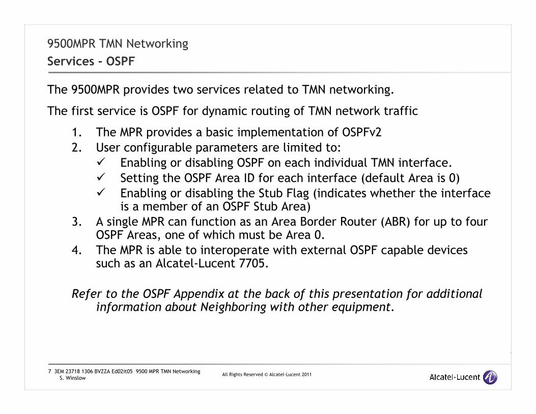
The 9500MPR provides two services related to TMN networking.
The first service is OSPF for dynamic routing of TMN network traffic
1. The MPR provides a basic implementation of OSPFv2
2. User configurable parameters are limited to:
� Enabling or disabling OSPF on each individual TMN interface.
� Setting the OSPF Area ID for each interface (default Area is 0)
� Enabling or disabling the Stub Flag (indicates whether the interface is a member of an OSPF Stub Area)
3. A single MPR can function as an Area Border Router (ABR) for up to four OSPF Areas, one of which must be Area 0.
4. The MPR is able to interoperate with external OSPF capable devices such as an Alcatel-Lucent 7705.
Refer to the OSPF Appendix at the back of this presentation for additional information about Neighboring with other equipment.

8 3EM 23718 1306 BVZZA Ed02it05 9500 MPR TMN Networking
S. WinslowAll Rights Reserved © Alcatel-Lucent 2011
9500MPR TMN Networking
Services - DHCP
The second 9500MPR service is a trivial DHCP server available only on the TMN Ethernet port
1. This limited server is intended to support dynamic address configuration of directly connected Craft computers.
2. Enabled by default, it can be disabled.
� This is the only user configurable option!
3. The DHCP server uses an address pool determined by the TMN Local Ethernet IP address and subnet.
4. The maximum number of Addresses managed by the DHCP Server is 10. Clients are served the same Netmask assigned to the TMN Local Ethernet interface and a Default Gateway set to be the TMN Local Ethernet IP address.
5. The Lease Time is fixed to 10 minutes.
Refer to the DHCP Appendix for more information on how address space for Leases is reserved.

9 3EM 23718 1306 BVZZA Ed02it05 9500 MPR TMN Networking
S. WinslowAll Rights Reserved © Alcatel-Lucent 2011
39500MPR TMN Networking
TMN IP Addresses

10 3EM 23718 1306 BVZZA Ed02it05 9500 MPR TMN Networking
S. WinslowAll Rights Reserved © Alcatel-Lucent 2011
9500MPR Networking
MPR Addresses
1. The first and primary address is the NE Local Address:
a) This is the Address of the MPR itself.
b) This is the address the Craft and SNMP Managers must use when monitoring or provisioning the NE.
c) All SNMP Traps or Notifications are issued from this address
d) All RF PPPoE connections terminating in this shelf (one per Direction) use this address as their PPP Endpoint Identifier.
Local Address:10.0.36.9
The 9500MPR can be configured with up to five addresses.

11 3EM 23718 1306 BVZZA Ed02it05 9500 MPR TMN Networking
S. WinslowAll Rights Reserved © Alcatel-Lucent 2011
9500MPR Networking
MPR Addresses
2. The TMN Ethernet interface address
a) This interface is enabled by default. This interface is intended for local Craft access
b) Can be connected to an external network.
3. Optional Port #4 TMN Ethernet interface address
a) This interface is disabled by default. When enabled, User Ethernet port #4 is reassigned as a TMN interface.
b) Intended for use when connecting to external networks to allow the TMN Ethernet interface to remain available for Local Craft access.
Port #4 TMNAddress: 192.168.10.0Netmask: 255.255.255.192
TMN EthernetAddress: 172.22.64.86Netmask: 255.255.255.248

12 3EM 23718 1306 BVZZA Ed02it05 9500 MPR TMN Networking
S. WinslowAll Rights Reserved © Alcatel-Lucent 2011
9500MPR Networking
MPR Addresses: In-Band interfaces
4. Optional TMN In-Band #1 Ethernet interface address
5. Optional TMN In-Band #2 Ethernet interface address
a) These interfaces are disabled by default. When a TMN In-Band interface is enabled it must be associated with at least one User Ethernet port and a unique VLAN Id must be assigned.
b) These interfaces are intended for connection to external networks.
TMN In-Band #1VLAN Id: 2152User Port: 2Address: 172.22.65.132Netmask: 255.255.255.224
TMN In-Band #2VLAN Id: 3720User Port: 1,3Address: 10.139.22.6Netmask: 255.255.255.248

13 3EM 23718 1306 BVZZA Ed02it05 9500 MPR TMN Networking
S. WinslowAll Rights Reserved © Alcatel-Lucent 2011
9500MPR Networking
MPR Addresses: In-Band interfaces
The primary differences between the In-Band interfaces and the other TMN interfaces are:
1) The user can provision one or more User Ethernet ports that willbe used with the In-Band interface
2) In-Band TMN Traffic is VLAN tagged with the user specified VLAN Id.
3) If multiple User Ethernet ports are enabled on an individual TMNIn-Band interface, the associated TMN VLAN will be switched between the member ports.
4) User Ethernet ports associated with TMN In-Band interfaces also carry other Layer 2 User Ethernet traffic.
� This is useful when it is desirable to transport TMN Traffic in a VLAN through the same physical interface used for carrying User Ethernet traffic.
Note: Since all TMN In-Band traffic is VLAN tagged, access to the TMN In-Band traffic requires interfacing with a VLAN aware external device, one that can be configured to use the same VLAN Id.
14 3EM 23718 1306 BVZZA Ed02it05 9500 MPR TMN Networking
S. WinslowAll Rights Reserved © Alcatel-Lucent 2011
9500MPR Networking
MPR Addresses
Tip: When assigning addresses to TMN Interfaces, the Local Address may be set to match the address of one of the
five TMN Interfaces, but no more than one.
The Local Address must match the TMN Interface address if it is in the same subnet.

15 3EM 23718 1306 BVZZA Ed02it05 9500 MPR TMN Networking
S. WinslowAll Rights Reserved © Alcatel-Lucent 2011
49500MPR TMN Networking
The TMN Network

16 3EM 23718 1306 BVZZA Ed02it05 9500 MPR TMN Networking
S. WinslowAll Rights Reserved © Alcatel-Lucent 2011
9500MPR Networking
The Basic TMN Network – RF PPP Links
•The RF PPP link comes up as soon as the Radio channel is operational.
•It doesn’t matter what Local IP Address is assigned at either end, as long as it is unique. When the Radio link is up, the routers are networked together and can exchange packets with each other.
•TMN packets exchanged between the routers travel over the RF link in the highest priority data queue.
Local Address:172.22.37.49
R RRF PPP Link
Local Address:10.3.27.5

17 3EM 23718 1306 BVZZA Ed02it05 9500 MPR TMN Networking
S. WinslowAll Rights Reserved © Alcatel-Lucent 2011
9500MPR Networking
The Basic TMN Network – RF PPP Links
•If we move beyond a single hop, when the RF links are up:
•The NE at Site A can communicate with Site B
•The NE at Site B can communicate with Site C
•but A cannot communicate with C until routing is configured.
•For routing to function, the NE addresses must all be unique. If there are any duplicate addresses, or if all addresses are the same (factory default), routing will fail!
•Routing can be configured dynamically or statically.
•The recommended configuration is to enable OSPF within the MPR network for dynamic routing.
Local Address:172.22.37.49
R RRF PPP Link
Local Address:10.3.27.5 Local Address:192.168.10.16
RRF PPP Link
Site A Site BSite C

18 3EM 23718 1306 BVZZA Ed02it05 9500 MPR TMN Networking
S. WinslowAll Rights Reserved © Alcatel-Lucent 2011
9500MPR Networking
The Basic TMN Network
•Before external devices can gain access to this network, at least one external TMN interface must be configured somewhere in this network.
•If we connect a properly addressed Craft computer to one of the TMN Ethernet Interfaces we should be able to communicate with all the MPRs in the network, as long as the Craft computer is configured to use the TMN Ethernet interface as the Gateway to the MPR network and OSPF is enabled or suitable static routes have been provisioned in the MPRs
•To contact each NE using the Craft application, specify the Local Address of each MPR: 192.168.25.66 and 172.22.37.49 in this example.
�If the MPR DHCP service is enabled and network interface of the Craft computer is set to “Obtain an IP address automatically”, the Craft computer will require no user action for proper network configuration when connecting via the TMN Ethernet Port.
Local Address:192.168.25.66TMN Ethernet Port: 10.0.2.1
Local Address:172.22.37.49
R RRF PPP Link
TMN Ethernet Network
Craft Computer
Craft Address:10.0.2.2Default Gateway: 10.0.2.1
19 3EM 23718 1306 BVZZA Ed02it05 9500 MPR TMN Networking
S. WinslowAll Rights Reserved © Alcatel-Lucent 2011
9500MPR Networking
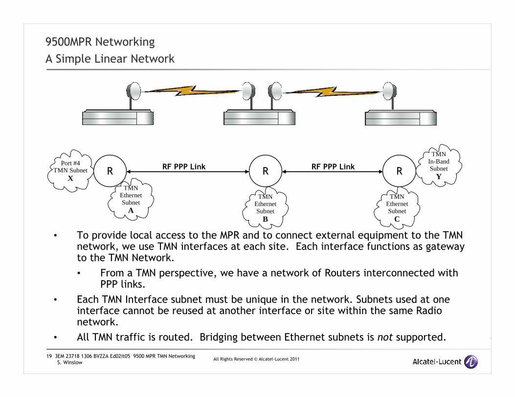
A Simple Linear Network
• To provide local access to the MPR and to connect external equipment to the TMN network, we use TMN interfaces at each site. Each interface functions as gateway to the TMN Network.
• From a TMN perspective, we have a network of Routers interconnected with PPP links.
• Each TMN Interface subnet must be unique in the network. Subnets used at one interface cannot be reused at another interface or site within the same Radio network.
• All TMN traffic is routed. Bridging between Ethernet subnets is not supported.
TMN Ethernet Subnet
A
TMN Ethernet Subnet
C
TMN Ethernet Subnet
B
R R RRF PPP Link RF PPP Link
Port #4 TMN Subnet
X
TMNIn-Band Subnet
Y

20 3EM 23718 1306 BVZZA Ed02it05 9500 MPR TMN Networking
S. WinslowAll Rights Reserved © Alcatel-Lucent 2011
9500MPR Networking
Supported TMN Layer 3 Network Topologies
• The TMN Layer 3 Network can be configured in Linear, Tree, Ring, or Mesh topologies.
• In Ring and Mesh networks, OSPF can dynamically update the routing to take advantage of alternate routes for TMN traffic in the event of a link failure.
• OSPF can also manage routes to prevent Layer 3 loops in the TMN Network.
Notice: The Ring and Mesh topologies depicted are ONLY for TMN Networking at Layer 3! All 9500MPR data transport is performed at Layer 2. It is mandatory that the data transport network be configured to prevent any Layer 2 loops through the appropriate provisioning of Ethernet Ring Protection, Port Segregation, or other physical means.
R R R R R R
R R
R R R
RR
R
R
RRLinear and Tree
Ring
Mesh
R
R R
R
RRR
R R
R
RR

21 3EM 23718 1306 BVZZA Ed02it05 9500 MPR TMN Networking
S. WinslowAll Rights Reserved © Alcatel-Lucent 2011
9500MPR Networking
Supported TMN Network Topologies
• MPR TMN Networks can have multiple external gateways that allow alternate management paths in the event of an outage.
• To make the best use of multiple gateways, OSPF must be enabled throughout the MPR TMN Network.
• To maximize the availability of alternate TMN network paths, the border routers of the MPR Network should Neighbor with external routers using OSPF and a dynamic routing protocol should be used in the External Network.
R R R R R R
R R
R R R
LinearR
R
R
ExternalNetwork SNMP
Manager
X
Management Traffic Path After a failure
R External Router

22 3EM 23718 1306 BVZZA Ed02it05 9500 MPR TMN Networking
S. WinslowAll Rights Reserved © Alcatel-Lucent 2011
59500MPR TMN Networking
Basic MPR Address Provisioning

23 3EM 23718 1306 BVZZA Ed02it05 9500 MPR TMN Networking
S. WinslowAll Rights Reserved © Alcatel-Lucent 2011
9500MPR Networking
MPR Addressing
How many addresses does an MPR need?
A better question might be:
How much address space does an MPR require?
To answer these questions, we need to know how the interfaces are used in various configurations.
Port #4 TMNAddress: 192.168.10.0Netmask: 255.255.255.192
TMN EthernetAddress: 172.22.64.86Netmask: 255.255.255.248
Local Address:10.0.36.9
TMN In-Band #1VLAN Id: 2152User Port: 2Address: 172.22.65.132Netmask: 255.255.255.224
TMN In-Band #2VLAN Id: 3720User Port: 1,5Address: 10.139.22.6Netmask: 255.255.255.248

24 3EM 23718 1306 BVZZA Ed02it05 9500 MPR TMN Networking
S. WinslowAll Rights Reserved © Alcatel-Lucent 2011
9500MPR Networking
MPR Addressing – Adding an MPR terminal to an existing Network
•If an MPR is connected to an existing external network defined by an external Router, the MPR only requires one IP Address.
•In this configuration, the TMN Ethernet interface is assigned an address and netmask from the existing subnet, and the MPR Local Address can be set to match. The MPR only will use only one IP Address.
•Craft connections access the MPR by connecting through the existing network.
*If an External DHCP server is present, the internal DHCP server for the TMN Ethernet Port MUST be disabled before connecting the MPR to the external network in order to prevent conflicts!
TMN EthernetAddress: 192.168.64.10Netmask: 255.255.255.240 (/28)Default External Gateway:192.168.64.1
Local Address:192.168.64.10
Router
External Network
192.168.64.1
Existing Network
192.168.64.0/28
*ExternalDHCP Server

25 3EM 23718 1306 BVZZA Ed02it05 9500 MPR TMN Networking
S. WinslowAll Rights Reserved © Alcatel-Lucent 2011
When an MPR installed at a location where no pre-existing external network is available, the MPR must, at a minimum, define a network that can be used for local Craft connections.
The smallest useable Ethernet network that can be defined for a TMN network interface is a /30. In this size network, only two useable addresses are available, one for the TMN Ethernet port and one for a Craft computer. If the TMN Ethernet interface is used for this function, the MPR internal DHCP server should be enabled to configure the network interface on the Craft computer when it connects.
In this example, the Local Address is set differently from the TMN Ethernet address. This means the MPR consumes the space of 5 IP addresses: 4 IP addresses for the TMN Ethernet (/30) network and one for the (different) Local Address.
9500MPR Networking
MPR Addressing – Basic Addressing
Remember: To provision or manage this NE, the Craft or SNMP Manager must connect using the 172.22.46.51 Local Address regardless of whether the physical connection is local or remote!
Local Address: 172.22.46.51
TMN Ethernet Network10.3.27.4 Network10.3.27.5 MPR TMN Ethernet Port10.3.27.6 Craft10.3.27.7 BroadcastNetmask: 255.255.255.252

26 3EM 23718 1306 BVZZA Ed02it05 9500 MPR TMN Networking
S. WinslowAll Rights Reserved © Alcatel-Lucent 2011
9500MPR Networking
MPR Addressing – Basic Addressing
In this example, we have three external devices requiring addresses. This requires a subnet large enough to a provide a total of four addresses: one for each of the three external devices plus the address for the Port#4 interface. The smallest subnet that can provide at least four useable addresses is a /29. The figure above shows how the addresses could be assigned.
By setting the Local Address and Port #4 address to be the same, the MPR will appear to be part of the same subnet as the external equipment from an SNMP management perspective.
As shown, the MPR (with external equipment) consume the space of eight addresses for the Port#4 TMN network, plus the space of four addresses for the TMN Ethernet network for a total of space of 12 addresses. Note: The spare addresses left over cannot be deployed at another site. They remain part of this subnet but are available for future site expansion.
Be aware that all TMN traffic is transported through the MPR network at high priority. Normal MPR TMN traffic is relatively low bandwidth. A high volume of traffic to and from external equipment may impact revenue bearing traffic!
If it is necessary to manage other external equipment at the site through the MPR TMN Network, Port #4 may be enabled in TMN mode and configured with a suitably sized network.
Local Address: 192.168.137.25
LocalNet
1 3
2
Port #4 TMN Ethernet Network192.168.137.24 Network Number192.168.137.25 MPR Port #4192.168.137.26 Ext Eqpt 1192.168.137.27 Ext Eqpt 2192.168.137.28 Ext Eqpt 3192.168.137.29 spare192.168.137.30 spare192.168.137.31 BroadcastNetmask: 255.255.255.248
TMN Ethernet Network10.3.27.4 Network Number10.3.27.5 MPR TMN Ethernet10.3.27.6 Craft10.3.27.7 BroadcastNetmask: 255.255.255.252

27 3EM 23718 1306 BVZZA Ed02it05 9500 MPR TMN Networking
S. WinslowAll Rights Reserved © Alcatel-Lucent 2011
9500MPR Networking
MPR Addressing – TMN In-Band Interface Example
•This example shows TMN In-Band #1 configured to use Optical SFP Port #5
•The MPR data traffic also flows through this same interface. The TMN In-Band VLAN Idmust be unique in the data flow so the TMN traffic can be identified and managed by external equipment.
•Intermediate routers forward the combined TMN In-Band VLAN and MPR data traffic to appropriate destinations. TMN In-Band traffic can be directed to the appropriate destination using the VLAN Id. The final external router strips the TMN VLAN Id tags from the TMN packets on egress and sends them to the Manager network.
•TMN Traffic coming from the Manager and destined for the TMN Network is tagged at ingress with the TMN VLAN Id before heading to the 9500MPR.
Local Address: 172.22.65.132
R
Manager Network
TMN VLAN Id: 2152
TMN Ethernet Network10.3.27.4 Network Number10.3.27.5 MPR TMN Ethernet10.3.27.6 Craft10.3.27.7 BroadcastNetmask: 255.255.255.252
TMN In-Band #1VLAN Id: 2152User Port: 5 (SFP)Address: 172.22.65.132Netmask: 255.255.255.224
MPR Data traffic and TMN In-Band VLAN backhaul through
a single interface.
MPREthernet Data
SNMPManager
RData
Network

28 3EM 23718 1306 BVZZA Ed02it05 9500 MPR TMN Networking
S. WinslowAll Rights Reserved © Alcatel-Lucent 2011
69500MPR TMN Networking
Interconnecting Multiple MPR Shelves

29 3EM 23718 1306 BVZZA Ed02it05 9500 MPR TMN Networking
S. WinslowAll Rights Reserved © Alcatel-Lucent 2011
Connecting multiple MPR shelves at a site using only the TMN Ethernet port
9500MPR Networking
MPR Addressing – Interconnecting Multiple Shelves with an External Switch
If each MPR Local Address matches the corresponding TMN Ethernet port address, the entire site will only consume the space of 8 addresses. Using an external Ethernet switch allows all NEs to be in the same subnet making the most efficient use of IP address space.
TMN Traffic flowing through the site via MPR #1 Dir #35 and MPR #3 Dir #38 must pass through the external switch.
Note: If the Core Card running the DHCP server (MPR #1) fails, manual configuration of the network interface on a Craft computer will be required to access the other radios.
MPR #1
TMN Ethernet Network10.3.27.64 Network10.3.27.65 DHCP Assigned10.3.27.66 DHCP Assigned10.3.27.67 MPR #110.3.27.68 MPR #2 (DHCP server disabled)10.3.27.69 MPR #3 (DHCP server disabled)10.3.27.70 Spare10.3.27.71 BroadcastNetmask: 255.255.255.248
MPR #3
MPR #2
External Switch
Local Craft
MPR #1 Dir #35
MPR #3 Dir #38
In this configuration, all TMN Ethernet ports are addressed in the same subnet and connected together with an external switch. DHCP is enabled on MPR #1 and disabled on MPR #2 and MPR #3.
The IP Address of MPR #1 is selected to be in the middle of the subnet to limit the number of DHCP addresses being reserved. Refer to the DHCP Appendix for details about how the MPR mini-DHCP server assigns lease addresses.

30 3EM 23718 1306 BVZZA Ed02it05 9500 MPR TMN Networking
S. WinslowAll Rights Reserved © Alcatel-Lucent 2011
Connecting multiple MPR shelves at a site using the Port #4 TMN interface
9500MPR Networking
MPR Addressing – Multiple Shelves with External Equipment and Switch
�All Port #4 TMN ports are addressed in the same /29 subnet and connected together with an external switch. External site equipment is connected to the TMN Network using via the switch.
�As before, TMN Traffic flowing through the site via MPR #1 Dir #35 and MPR #3 Dir #38 will pass through the external switch.
�In this configuration, each TMN Ethernet interface is configured with it’s own unique /30 subnet and the DHCP server in each MPR is enabled (details not shown). This configuration permits independent local Craft access to each MPR as well as the TMN Network . This solves the problem of the previous example of a Core failure taking out the only active DHCP server at the expense of more address space.
�The site consumes 20 addresses, eight for the /29 and twelve for the three /30 Craft networks.
MPR #1Port #4 TMN Network10.3.27.64 Network10.3.27.65 MPR #110.3.27.66 MPR #210.3.27.67 MPR #310.3.27.68 External Eqpt #110.3.27.69 External Epqt #210.3.27.70 Spare10.3.27.71 BroadcastNetmask: 255.255.255.248
MPR #3
MPR #2
External Switch
Local Craft
MPR #1 Dir #35
MPR #3 Dir #38
Ext #1
Ext #2
Local Craft
Local Craft

31 3EM 23718 1306 BVZZA Ed02it05 9500 MPR TMN Networking
S. WinslowAll Rights Reserved © Alcatel-Lucent 2011
Connecting multiple MPR shelves at a site without an external switch
9500MPR Networking
MPR Addressing – Interconnecting Multiple Shelves Without an External Switch
�This example uses four /30 subnets, and connects three MPR shelves and one external device without the use of an external switch. The table in the example shows the addresses in the four subnets as being adjacent, but this is not a requirement.
�One TMN Ethernet port is dedicated for Craft use with DHCP enabled. Craft addressing is not shown.
�The path for TMN Traffic flowing through the site via Dir #35 and Dir #38 is indicated. In this example, TMN traffic going through the site must pass through MPR #2 with an additional routing hop delay.
MPR #1
MPR #3
MPR #2
MPR #1 Dir #35
MPR #3 Dir #38
Ext #1
Local Craft
CommentEquipmentIP Addr
Broadcast10.3.27.79
Ext #110.3.27.78
MPR #3 Port #410.3.27.77
Netmask: 255.255.255.252Network10.3.27.76
Broadcast10.3.27.75
Also MPR #3 Local AddressMPR #3 TMN Eth10.3.27.74
Also MPR #2 Local AddressMPR #2 TMN Eth10.3.27.73
Netmask: 255.255.255.252Network10.3.27.72
Broadcast10.3.27.71
MPR #2 Port #410.3.27.70
MPR #1 Port #410.3.27.69
Netmask: 255.255.255.252Network10.3.27.68
Broadcast10.3.27.67
DHCP AssignedCraft10.3.27.66
Also MPR #1 Local AddressMPR #1 TMN Eth10.3.27.65
Netmask: 255.255.255.252Network10.3.27.64

32 3EM 23718 1306 BVZZA Ed02it05 9500 MPR TMN Networking
S. WinslowAll Rights Reserved © Alcatel-Lucent 2011
Connecting multiple MPR shelves at a site using TMN In-Band interfaces and no external switch
9500MPR Networking
MPR Addressing – Shelf Interconnect using TMN In-Band Interfaces
� This example uses a total of five /30 subnets. This configuration is expensive in terms of the amount of address space required (Space of 20 addresses for 6 devices) but allows interconnecting with no external switch while supporting one external TMN device per MPR shelf.
� If External devices are not required, the Port #4 interfaces could be disabled, eliminating those subnets. This would improve address efficiency.
� The two TMN Ethernet ports are dedicated for Craft use with DHCP enabled. Craft addressing is not shown, but would be the same as in other examples.
� The path for TMN Traffic flowing through the site via Dir #35 and Dir #38 is via the TMN In-Band interconnection. Note that the Port #1 to Port #1 connection ties together not only the TMN In-Band but also bridges the MPR Layer 2 Ethernet traffic between the two shelves! Note that MPR port segregation cannot be used to prevent this behavior since it would also block TMN In-Band operation. If this behavior is not desired, use another configuration to interconnect TMN traffic!
MPR #1
MPR #2
MPR #1 Dir #35
MPR #2 Dir #38
Ext #2
Local Craft
CommentEquipmentIP Addr
Broadcast10.3.27.75
External EquipmentExt #210.3.27.74
Also MPR #2 Local AddressMPR #2 Port #410.3.27.73
Netmask: 255.255.255.252Network10.3.27.72
Broadcast10.3.27.71
Eth Port #3, Vlan ID: 1001MPR #2 In-band #110.3.27.70
Eth Port #3, Vlan ID: 1001MPR #1 In-Band #110.3.27.69
Netmask: 255.255.255.252Network10.3.27.68
Broadcast10.3.27.67
External EquipmentExt #110.3.27.66
Also MPR #1 Local AddressMPR #1 Port #410.3.27.65
Netmask: 255.255.255.252Network10.3.27.64
Local Craft
Ext #1

33 3EM 23718 1306 BVZZA Ed02it05 9500 MPR TMN Networking
S. WinslowAll Rights Reserved © Alcatel-Lucent 2011
79500MPR TMN Networking
Craft and Management Communication
Requirements

34 3EM 23718 1306 BVZZA Ed02it05 9500 MPR TMN Networking
S. WinslowAll Rights Reserved © Alcatel-Lucent 2011
9500MPR Networking
Management
We know up to five addresses can be assigned to each MPR,
Which address must be used for Craft access?
Which address must be used for SNMP Management?
Port #4 TMNAddress: 192.168.10.0Netmask: 255.255.255.192
TMN EthernetAddress: 10.0.36.9Netmask: 255.255.255.248
Local Address:172.22.46.51?
? ?
TMN In-Band Interface #1Address: 10.78.101.0Netmask: 255.255.255.192
TMN In-Band Interface #2Address: 172.22.65.0Netmask: 255.255.255.192 ?
?

35 3EM 23718 1306 BVZZA Ed02it05 9500 MPR TMN Networking
S. WinslowAll Rights Reserved © Alcatel-Lucent 2011
9500MPR Networking
Management
The Local Address is used to provision and Manage the MPR.
Regardless of how either the TMN Ethernet, Port #4 TMN, or TMN In-Band Interfaces are configured, the Local Address is the one to specify in NEtO when using the Craft, or at an SNMP Manager.
Port #4 TMNAddress: xxx.xxx.xxx.xxxNetmask: nnn.nnn.nnn.nnn
TMN EthernetAddress: yyy.yyy.yyy.yyyNetmask: mmm.mmm.mmm.mmm
Local Address:172.22.46.51
Connecting to the wrong address is the primary reason for provisioning problems with the MPR !
NEtO Example
TMN In-Band #1Address: z.z.z.zNetmask: nnn.nnn.nnn.nnn
TMN In-Band #2Address: w.w.w.wNetmask:nnn.nnn.nnn.nnn

36 3EM 23718 1306 BVZZA Ed02it05 9500 MPR TMN Networking
S. WinslowAll Rights Reserved © Alcatel-Lucent 2011
9500MPR Networking
Management
When a Craft computer is connected to the TMN Ethernet subnet, NEtO will find MPR Local Addresses advertised by the MPR Discovery Protocol. Double-clicking on a Discovered NE entry will copy the address to the correct location for connection.
Local Address:172.22.46.36
NEtO Example

37 3EM 23718 1306 BVZZA Ed02it05 9500 MPR TMN Networking
S. WinslowAll Rights Reserved © Alcatel-Lucent 2011
9500MPR Networking
Management
Why Must the Local Address be used for provisioning?
1. The MPR SNMP Agent responds at all the MPR IP Addresses, but SNMP Traps and Notifications only originate from the Local Address.
• When the Craft performs complex SNMP operations such as cross-connections, it expects SNMP Notifications verifying completion of each step. The Craft will be listening for these Notifications to come from the address specified in NEtO. It will ignore Notifications that come from other (unknown) addresses. If the Craft does not receive the proper responses, provisioning fails.
2. SNMP Managers must know which IP Addresses will be sending Traps so that Alarms can be associated with the proper NE.
• The 5620SAM is aware of the MPR behavior. When the SAM identifies an MPR during discovery, it inspects the appropriate SNMP MIB objects to determine the Local Address of that NE. When Traps or Notifications arrive, they can be correlated with the proper NE.
• Third party Managers using auto-discovery in an MPR network will likely find a mix of various TMN Ethernet interface and Local Addresses unless the discovery can be restricted to just the range of addresses used for Local Addresses. The usual symptoms of simply auto-discovering in an MPR network are multiple copies of each NE, one for each unique interface IP address, or by Traps that arrive from ‘unknown’ NEs, where the source address correlates with an MPR Local Address somewhere in the network.

38 3EM 23718 1306 BVZZA Ed02it05 9500 MPR TMN Networking
S. WinslowAll Rights Reserved © Alcatel-Lucent 2011
9500MPR Networking
Network Communication
• Communication requirements with external networks
• SNMP packets from the Local Address of each NE must have a route to the managers. This is usually provided by either a Static Default Route at the MPR Network borders, or learned via OSPF from external Neighboring routers.
• External routers must be either manually configured to use an MPR as the gateway to the network of Local Addresses or they must learn the gateways to the MPR network exchanging routes with an MPR using OSPF.
• TMN In-Band interfaces must connect to VLAN aware equipment.
TMN Ethernet Subnet
A
TMN Ethernet Subnet
C
TMN Ethernet Subnet
B
R R RRF PPP Link RF PPP LinkPort #4
TMN SubnetX
TMN In-Band Subnet
Y
Local Address 1 Local Address 2 Local Address 3
R
ExternalNetwork SNMP
Manager
Local Craft
Local Craft
Local Craft
VLAN AwareRouter
ExternalNetwork
SNMPManager
VLAN
Non-VLAN Aware
equipment

39 3EM 23718 1306 BVZZA Ed02it05 9500 MPR TMN Networking
S. WinslowAll Rights Reserved © Alcatel-Lucent 2011
89500MPR TMN Networking
Planning and Addressing a Network

40 3EM 23718 1306 BVZZA Ed02it05 9500 MPR TMN Networking
S. WinslowAll Rights Reserved © Alcatel-Lucent 2011
9500MPR TMN Networking
TMN Network Planning
�Consider the above network. For TMN purposes, it is a combination of Linear and Ring topologies.
�External equipment to be managed is located at sites B, D, and E.
�How could this network be addressed?
A B
C
D
E
F
SiteNetwork
SiteNetwork
R1
R2
ExternalNetwork
SNMPManager
1 2 3
1 2
Fiber or other
ExtDHCP
Server
1
Existing external equipment

41 3EM 23718 1306 BVZZA Ed02it05 9500 MPR TMN Networking
S. WinslowAll Rights Reserved © Alcatel-Lucent 2011
9500MPR TMN Networking
TMN Network Planning
�Definitions for the Example:
�Site A is an existing site where other equipment is already installed. An MPR will be added to the site. The existing subnet is 192.168.19.0/27. Router R1 is at 192.168.19.1. The address available for the MPR is 192.168.19.23. A local external DHCP server is available.
�Site B is a junction. There are three external devices to be managed via the TMN Network.
�Site C is a repeater with no external equipment.
�Site D is a repeater with one external device.
�Site E is a repeater with two external devices. A new router (R2) connected via an external link will be added to provide an alternate pathway for TMN Traffic. The MPR DHCP server will be used to provide DHCP services for all transient craft devices at this site.
�Site F is a repeater with no external equipment.

42 3EM 23718 1306 BVZZA Ed02it05 9500 MPR TMN Networking
S. WinslowAll Rights Reserved © Alcatel-Lucent 2011
9500MPR TMN Networking
TMN Network Planning
�Definitions for the Example (continued)
�OSPF will be enabled within the network
�The recommended configuration is to enable OSPF within the MPR network whenever
possible. Correctly configuring Static routing internally within the MPR network can be
very complex for anything other than trivial linear networks and is not recommended.
�The MPR network will be an Autonomous (isolated) OSPF network. It will use Static routing at the borders
�The use of OSPF or Static routing between the MPR network border and external networks is a network design choice. When OSPF monitors the status of a link carrying TMN Traffic, if the link fails, it can reroute the TMN traffic to use an alternate gateway provided one is available.
�At site A where an external network is available, the MPR will be a member of the external network, using the Port #4 TMN interface. The MPR will be configured to use router R1 as the Default Gateway for reaching all other external networks.
�At site E, a new local network will be defined using router R2. This network will provide an alternate external route for TMN traffic. The MPR at site E will be come a member of this network and will use Router R2 as the Default Gateway to reach the external networks
�The MPR Local Address will be set to match the TMN Ethernet Port address at all sites.
�DHCP will be used for configuration of Craft computers.
�Using the MPR internal DHCP server whenever possible is recommended. The internal DHCP server will correctly configure external Craft computers to communicate with the local MPR and the greater TMN Network. This eliminates the need for users to know how to manually configure a laptop at each site. The user only needs to know the Local Addresses of the equipment to connect using the NEtO/Craft.
43 3EM 23718 1306 BVZZA Ed02it05 9500 MPR TMN Networking
S. WinslowAll Rights Reserved © Alcatel-Lucent 2011
9500MPR TMN Networking
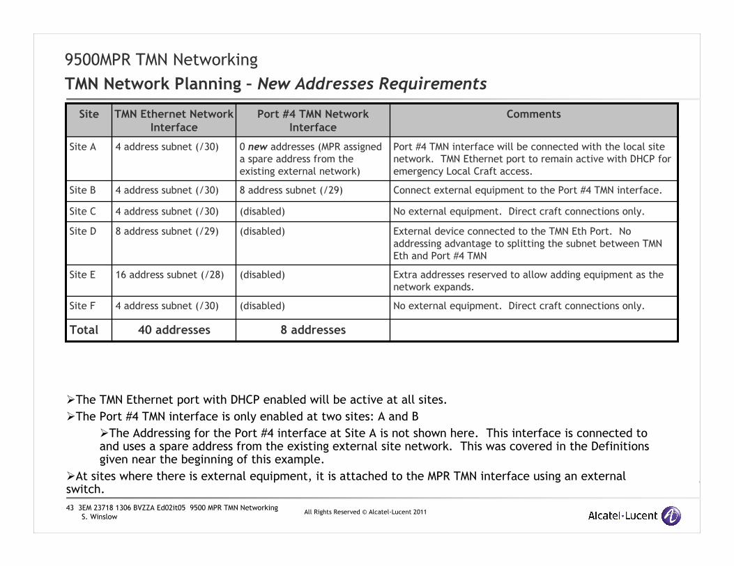
TMN Network Planning – New Addresses Requirements
�The TMN Ethernet port with DHCP enabled will be active at all sites.
�The Port #4 TMN interface is only enabled at two sites: A and B
�The Addressing for the Port #4 interface at Site A is not shown here. This interface is connected to and uses a spare address from the existing external site network. This was covered in the Definitions given near the beginning of this example.
�At sites where there is external equipment, it is attached to the MPR TMN interface using an external switch.
No external equipment. Direct craft connections only.(disabled)4 address subnet (/30)Site F
8 addresses40 addressesTotal
(disabled)
(disabled)
(disabled)
8 address subnet (/29)
0 new addresses (MPR assigned
a spare address from the
existing external network)
Port #4 TMN Network Interface
Extra addresses reserved to allow adding equipment as the
network expands.
16 address subnet (/28)Site E
External device connected to the TMN Eth Port. No
addressing advantage to splitting the subnet between TMN
Eth and Port #4 TMN
8 address subnet (/29)Site D
No external equipment. Direct craft connections only.4 address subnet (/30)Site C
Connect external equipment to the Port #4 TMN interface. 4 address subnet (/30)Site B
Port #4 TMN interface will be connected with the local site
network. TMN Ethernet port to remain active with DHCP for
emergency Local Craft access.
4 address subnet (/30)Site A
CommentsTMN Ethernet Network Interface
Site

44 3EM 23718 1306 BVZZA Ed02it05 9500 MPR TMN Networking
S. WinslowAll Rights Reserved © Alcatel-Lucent 2011
9500MPR TMN Networking
TMN Network Planning
�With the network plan shown in the previous table, this network requires the space of at least 48 addresses.
�Of the 48:
�6 addresses are assigned as MPR Local Address/TMN Ethernet addresses
�1 address is assigned as a TMN Port #4 address
�7 addresses are assigned to external equipment (including router R2)
�14 addresses are reserved for use by the internal MPR DHCP servers
�6 Spare addresses
�Netmasks force subnets start and end on specific boundaries. For example a subnet containing 8 addresses must start at an address that is evenly divisible by 8.
�Before we request address space from our Network Administrator, we first need to verify what size address block will hold all our subnets. This is shown on the next slide.

45 3EM 23718 1306 BVZZA Ed02it05 9500 MPR TMN Networking
S. WinslowAll Rights Reserved © Alcatel-Lucent 2011
9500MPR TMN Networking
TMN Network Planning
Netmask: 255.255.255.252
MPR A TMN Ethernet Subnet
Broadcastxxx.xxx.xxx.3
DHCP Assignedxxx.xxx.xxx.2
A TMN Eth Portxxx.xxx.xxx.1
Network (/30)xxx.xxx.xxx.0
Netmask: 255.255.255.248
MPR D TMN Ethernet Subnet
Broadcastxxx.xxx.xxx.31
Sparexxx.xxx.xxx.30
D Ext Eqpt 1xxx.xxx.xxx.29
D TMN Eth Portxxx.xxx.xxx.28
DHCP Assignedxxx.xxx.xxx.27
DHCP Assignedxxx.xxx.xxx.26
DHCP Assignedxxx.xxx.xxx.25
Network (/29)xxx.xxx.xxx.24
Netmask: 255.255.255.240
MPR E TMN Ethernet Subnet
Network (/28)xxx.xxx.xxx.32
DHCP Assignedxxx.xxx.xxx.33
DHCP Assignedxxx.xxx.xxx.34
DHCP Assignedxxx.xxx.xxx.35
DHCP Assignedxxx.xxx.xxx.36
DHCP Assignedxxx.xxx.xxx.37
DHCP Assignedxxx.xxx.xxx.38
DHCP Assignedxxx.xxx.xxx.39
E TMN Eth Port xxx.xxx.xxx.40
E Ext Eqpt 1xxx.xxx.xxx.41
E Ext Eqpt 2xxx.xxx.xxx.42
Sparexxx.xxx.xxx.43
Sparexxx.xxx.xxx.44
Sparexxx.xxx.xxx.45
Router R2xxx.xxx.xxx.46
Broadcastxxx.xxx.xxx.47
This shows how the required subnets could map into an arbitrary block of 48 contiguous addresses. Other arrangements are possible. Notice the addresses for MPR F are between the addresses of MPR C and MPR D. With OSPF enabled, there will be no routing complications resulting from this choice.
Netmask: 255.255.255.252
MPR C TMN Ethernet Subnet
Network (/30)xxx.xxx.xxx.16
C TMN Eth Portxxx.xxx.xxx.17
DHCP Assignedxxx.xxx.xxx.18
Broadcastxxx.xxx.xxx.19
Netmask: 255.255.255.252
MPR F TMN Ethernet Subnet
Broadcastxxx.xxx.xxx.23
DHCP Assignedxxx.xxx.xxx.22
F TMN Eth Portxxx.xxx.xxx.21
Network (/30)xxx.xxx.xxx.20
Netmask: 255.255.255.248
MPR B Port #4 TMN Subnet
Broadcastxxx.xxx.xxx.15
Sparexxx.xxx.xxx.14
Sparexxx.xxx.xxx.13
B Ext Eqpt 3 xxx.xxx.xxx.12
B Ext Eqpt 2xxx.xxx.xxx.11
B Ext Eqpt 1xxx.xxx.xxx.10
B Port #4xxx.xxx.xxx.9
Network (/29)xxx.xxx.xxx.8
Netmask: 255.255.255.252
MPR B TMN Ethernet Subnet
Broadcastxxx.xxx.xxx.7
DHCP Assignedxxx.xxx.xxx.6
B TMN Eth Portxxx.xxx.xxx.5
Network (/30)xxx.xxx.xxx.4

46 3EM 23718 1306 BVZZA Ed02it05 9500 MPR TMN Networking
S. WinslowAll Rights Reserved © Alcatel-Lucent 2011
9500MPR TMN Networking
TMN Network Planning
�The previous slide shows how this network design will fit within the total space of 48 addresses. This is the minimum sized block number of addresses we must request to deploy this network.
�Depending on the availability of IP address space:
�we could be assigned a single /26 block with 64 addresses.
�If the availability of new address space is limited, we might be assigned exactly 48 addresses broken down as:
�a /27 block (32 addresses) plus
�a /28 (16 addresses)
�If assigned separately like this, the address blocks might not be contiguous.
�For this example, we’ll assume we’ve been assigned 172.28.137.64 /26
�The block contains 64 contiguous addresses ranging from 172.28.137.64 to 172.28.137.127
�We’ll further divide this block of addresses into our own subnets following the plan.

47 3EM 23718 1306 BVZZA Ed02it05 9500 MPR TMN Networking
S. WinslowAll Rights Reserved © Alcatel-Lucent 2011
9500MPR TMN Networking
TMN Network Planning
Netmask: 255.255.255.252
MPR A TMN Ethernet Subnet
Broadcast172.28.137.67
DHCP Assigned172.28.137.66
A TMN Eth Port (L)172.28.137.65
Network (/30)172.28.137.64
Netmask: 255.255.255.248
MPR D TMN Ethernet Subnet
Broadcast172.28.137.95
Spare172.28.137.94
D Ext Eqpt 1172.28.137.93
D TMN Eth Port (L)172.28.137.92
DHCP Assigned172.28.137.91
DHCP Assigned172.28.137.90
DHCP Assigned172.28.137.89
Network (/29)172.28.137.88
Netmask: 255.255.255.240
MPR E TMN Ethernet Subnet
Network (/28)172.28.137.96
DHCP Assigned172.28.137.97
DHCP Assigned172.28.137.98
DHCP Assigned172.28.137.99
DHCP Assigned172.28.137.100
DHCP Assigned172.28.137.101
DHCP Assigned172.28.137.102
DHCP Assigned172.28.137.103
E TMN Eth Port (L)172.28.137.104
E Ext Eqpt 1172.28.137.105
E Ext Eqpt 2172.28.137.106
Spare172.28.137.107
Spare172.28.137.108
Spare172.28.137.109
Router R2172.28.137.110
Broadcast172.28.137.111
Netmask: 255.255.255.252
MPR C TMN Ethernet Subnet
Network (/30)172.28.137.80
C TMN Eth Port (L)172.28.137.81
DHCP Assigned172.28.137.82
Broadcast172.28.137.83
Netmask: 255.255.255.252
MPR F TMN Ethernet Subnet
Broadcast172.28.137.87
DHCP Assigned172.28.137.86
F TMN Eth Port (L)172.28.137.85
Network (/30)172.28.137.84
Netmask: 255.255.255.248
MPR B Port #4 TMN Subnet
Broadcast172.28.137.79
Spare172.28.137.78
Spare172.28.137.77
B Ext Eqpt 3 172.28.137.76
B Ext Eqpt 2172.28.137.75
B Ext Eqpt 1172.28.137.74
B Port #4172.28.137.73
Network (/29)172.28.137.72
Netmask: 255.255.255.252
MPR B TMN Ethernet Subnet
Broadcast172.28.137.71
DHCP Assigned172.28.137.70
B TMN Eth Port (L)172.28.137.69
Network (/30)172.28.137.68
Merging our assigned addresses into the tables shows how to address our equipment.
MPR Local addresses will be set to match the TMN Ethernet Port as specified in the Plan and are labeled (L).
MPR A Port #4 TMN Subnet
MPR A Port #4192.168.19.23
Router R1192.168.19.1
Netmask: 255.255.255.224
Address assignments from the existing external network at Site A.

48 3EM 23718 1306 BVZZA Ed02it05 9500 MPR TMN Networking
S. WinslowAll Rights Reserved © Alcatel-Lucent 2011
9500MPR TMN Networking
TMN Network Planning
Sixteen addresses out of the assigned 64 remain unused.
Unused172.28.137.127
Unused172.28.137.126
Unused172.28.137.125
Unused172.28.137.124
Unused172.28.137.123
Unused172.28.137.122
Unused172.28.137.121
Unused172.28.137.120
Unused172.28.137.119
Unused172.28.137.118
Unused172.28.137.117
Unused172.28.137.116
Unused172.28.137.115
Unused172.28.137.114
Unused172.28.137.113
Unused172.28.137.112

49 3EM 23718 1306 BVZZA Ed02it05 9500 MPR TMN Networking
S. WinslowAll Rights Reserved © Alcatel-Lucent 2011
9500MPR TMN Networking
TMN Network Planning
Per the plan:
A. The MPR at Site A will be configured with a static route to use R1 as it’s default gateway.
� This is required so that TMN traffic destined to leave the MPR TMN Network will have a way out
B. Conversely, External router R1 must be configured to use MPR A as a gateway to access the network 172.28.137.64 /26
C. The MPR at site E will be configured with a static route to use R2 as it’s default gateway
� This defines an alternate gateway for traffic leaving the MPR TMN network.
D. External router R2 must also be configured to use MPR E as a gateway for network 172.28.137.64 /26
� This route provides an alternate way into the MPR TMN Network.

50 3EM 23718 1306 BVZZA Ed02it05 9500 MPR TMN Networking
S. WinslowAll Rights Reserved © Alcatel-Lucent 2011
9500MPR TMN Networking
TMN Network Planning – Growing the network
�What if the network grows and we need to expand by adding Sites G, H, J, and K?
�What if Site F, where we originally allowed for no expansion needs a new external device?
�What if the old expansion plans change, and the additional external equipment planned for site E will now be deployed at site H, leaving site E with an excess of unused addresses?
�We know we can assign some of the addresses from space left over from the original /26, but we don’t have enough addresses for all new the equipment. We’ll have to request additional address space.
A B
C
D
E
F
G H
SiteNetwork
SiteNetwork
R1
R2
ExternalNetwork
SNMPManager
1 2 3
1 2
1
J
K
1
Fiber or other
ExtDHCP
Server
3 4 5
1
1

51 3EM 23718 1306 BVZZA Ed02it05 9500 MPR TMN Networking
S. WinslowAll Rights Reserved © Alcatel-Lucent 2011
9500MPR TMN Networking
TMN Network Planning – Growing the network
�Expansion of the network will require the space of 32 addresses, 16 of which were left over from our original allocation, and 16 new addresses.
�We request a new block of 16 addresses:
�Our new address block assigned is: 172.30.10.0 /28
(disabled)8 address subnet (/29)Site K
(Keep existing subnet)
Extra address space no longer needed. Split 16
address subnet, allocating 8 addresses to Port #4 TMN and 4 addresses to TMN Ethernet. Redeploy
recovered 4 addresses to site F.
8 address subnet (/29)
(local reallocation)
Original 16 address subnet now a 4 address subnet (/30)
Site E
8 new addresses
(disabled)
8 address subnet (/29)
(disabled)
4 address subnet (/30)
(reallocated addresses
from Site E)
Port #4 TMN Network
24 new addressesTotal
8 address subnet (/29)Site J
External eqpt connected to Port #4 TMN interface. 4 address subnet (/30)Site H
No external equipment. Direct craft connections
only.
4 address subnet (/30)Site G
Add subnet to Port #4 TMN interface for new
equipment, using the address space recovered from
Site E.
Site F
CommentsTMN Ethernet NetworkSite
Here’s the new plan:

52 3EM 23718 1306 BVZZA Ed02it05 9500 MPR TMN Networking
S. WinslowAll Rights Reserved © Alcatel-Lucent 2011
9500MPR TMN Networking
TMN Network Planning
Netmask: 255.255.255.252
MPR A TMN Ethernet Subnet
Broadcast172.28.137.67
DHCP Assigned172.28.137.66
A TMN Eth Port (L)172.28.137.65
Network (/30)172.28.137.64
Netmask: 255.255.255.248
MPR D TMN Ethernet Subnet
Broadcast172.28.137.95
Spare172.28.137.94
D Ext Eqpt 1172.28.137.93
D TMN Eth Port (L)172.28.137.92
DHCP Assigned172.28.137.91
DHCP Assigned172.28.137.90
DHCP Assigned172.28.137.89
Network (/29)172.28.137.88
Netmask: 255.255.255.252
MPR C TMN Ethernet Subnet
Network (/30)172.28.137.80
C TMN Eth Port (L)172.28.137.81
DHCP Assigned172.28.137.82
Broadcast172.28.137.83
Netmask: 255.255.255.248
MPR B Port #4 TMN Subnet
Broadcast172.28.137.79
Spare172.28.137.78
Spare172.28.137.77
B Ext Eqpt 3 172.28.137.76
B Ext Eqpt 2172.28.137.75
B Ext Eqpt 1172.28.137.74
B Port #4172.28.137.73
Network (/29)172.28.137.72
Netmask: 255.255.255.252
MPR B TMN Ethernet Subnet
Broadcast172.28.137.71
DHCP Assigned172.28.137.70
B TMN Eth Port (L)172.28.137.69
Network (/30)172.28.137.68
With the new expanded network plan, original subnets at site A, B,C, D, and the TMN Ethernet subnet at site F remain unchanged. The addresses are repeated here:
Netmask: 255.255.255.252
MPR F TMN Ethernet Subnet
Broadcast172.28.137.87
DHCP Assigned172.28.137.86
F TMN Eth Port (L)172.28.137.85
Network (/30)172.28.137.84

53 3EM 23718 1306 BVZZA Ed02it05 9500 MPR TMN Networking
S. WinslowAll Rights Reserved © Alcatel-Lucent 2011
9500MPR TMN Networking
TMN Network Planning
Netmask: 255.255.255.240
MPR E TMN Ethernet Subnet
Network (/28)172.28.137.96
DHCP Assigned172.28.137.97
DHCP Assigned172.28.137.98
DHCP Assigned172.28.137.99
DHCP Assigned172.28.137.100
DHCP Assigned172.28.137.101
DHCP Assigned172.28.137.102
DHCP Assigned172.28.137.103
E TMN Eth Port (L)172.28.137.104
E Ext Eqpt 1172.28.137.105
E Ext Eqpt 2172.28.137.106
Spare172.28.137.107
Spare172.28.137.108
Spare172.28.137.109
Router R2172.28.137.110
Broadcast172.28.137.111
MPR E Port #4 TMN Subnet
Netmask: 255.255.255.248
Broadcast172.28.137.111
Router R2172.28.137.110
MPR E Port #4172.28.137.109
Spare172.28.137.108
Spare172.28.137.107
E Ext Eqpt 2172.28.137.106
E Ext Eqpt 1172.28.137.105
Network (/29)172.28.137.104
MPR E TMN Ethernet Subnet
Netmask: 255.255.255.248
Broadcast172.28.137.99
DHCP Assigned172.28.137.98
MPR E TMN Eth (L)172.28.137.97
Network (/30)172.28.137.96
This is how the old subnet E can be split to recover some unused address space. Half the address space with the external equipment moves to the Site E Port #4 TMN subnet with a new netmask. Four addresses from the original subnet remain assigned to the MPR E TMN Eth subnet with a new netmask. The remaining four addresses are relocated to Site F as a new Port #4 subnet. New or changed addressing parameters are highlighted in red.
MPR F Port #4 TMN Subnet
Netmask: 255.255.255.252
Broadcast172.28.137.103
DHCP Assigned172.28.137.102
MPR F Port #4172.28.137.101
Network (/30)172.28.137.100
OLD
NEW

54 3EM 23718 1306 BVZZA Ed02it05 9500 MPR TMN Networking
S. WinslowAll Rights Reserved © Alcatel-Lucent 2011
9500MPR TMN Networking
TMN Network Planning – Growing the Network
MPR G TMN Ethernet Subnet
Netmask: 255.255.252
Broadcast172.28.137.115
DHCP Assigned172.28.137.114
MPR G TMN Eth (L)172.28.137.113
Network (/30)172.28.137.112
MPR H Port #4 TMN Subnet
Netmask: 255.255.255.248
Broadcast172.28.137.127
Spare172.28.137.126
Spare172.28.137.125
H Ext Eqpt 3 172.28.137.124
H Ext Eqpt 2172.28.137.123
H Ext Eqpt 1172.28.137.122
MPR H Port #4172.28.137.121
Network (/29)172.28.137.120
The unused 16 addresses from the original /26 allocation are split into subnets and assigned at sites G and H.
MPR H TMN Ethernet Subnet
Netmask: 255.255.255.252
Broadcast172.28.137.119
DHCP Assigned172.28.137.118
MPR H TMN Eth (L)172.28.137.117
Network (/30)172.28.137.116

55 3EM 23718 1306 BVZZA Ed02it05 9500 MPR TMN Networking
S. WinslowAll Rights Reserved © Alcatel-Lucent 2011
9500MPR TMN Networking
TMN Network Planning – Growing the Network
MPR J TMN Ethernet Subnet
Netmask: 255.255.255.248
Broadcast172.30.10.7
Spare172.30.10.6
J Ext Eqpt 1172.30.10.5
MPR J TMN Eth (L)172.30.10.4
DHCP Assigned172.30.10.3
DHCP Assigned172.30.10.2
DHCP Assigned172.30.10.1
Network (/29)172.30.10.0
•This slide shows address assignments using the new block of 16 addresses
•OSPF will manage the necessary route changes within the MPR TMN Network.
•External routers R1 and R2 will need additional static routes using MPR A and MPR E respectively as gateways to access the new 172.30.10.0/28 addresses.
•With OSPF managing routes within the MPR network and DHCP configuring the Craft computers these are the only routing changes required.
MPR K TMN Ethernet Subnet
Netmask: 255.255.255.248
Broadcast172.30.10.15
Spare172.30.10.14
K Ext Eqpt 1172.30.10.13
MPR K TMN Eth (L)172.30.10.12
DHCP Assigned172.30.10.11
DHCP Assigned172.30.10.10
DHCP Assigned172.30.10.9
Network (/29)172.30.10.8
56 3EM 23718 1306 BVZZA Ed02it05 9500 MPR TMN Networking
S. WinslowAll Rights Reserved © Alcatel-Lucent 2011
99500MPR TMN Networking
Configuring the MPR
57 3EM 23718 1306 BVZZA Ed02it05 9500 MPR TMN Networking
S. WinslowAll Rights Reserved © Alcatel-Lucent 2011
9500MPR Networking
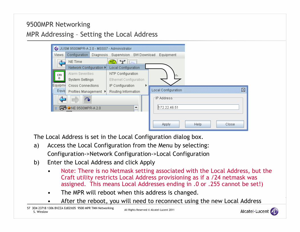
MPR Addressing – Setting the Local Address
The Local Address is set in the Local Configuration dialog box.
a) Access the Local Configuration from the Menu by selecting:
Configuration->Network Configuration->Local Configuration
b) Enter the Local Address and click Apply
• Note: There is no Netmask setting associated with the Local Address, but the Craft utility restricts Local Address provisioning as if a /24 netmask was assigned. This means Local Addresses ending in .0 or .255 cannot be set!)
• The MPR will reboot when this address is changed.
• After the reboot, you will need to reconnect using the new Local Address

58 3EM 23718 1306 BVZZA Ed02it05 9500 MPR TMN Networking
S. WinslowAll Rights Reserved © Alcatel-Lucent 2011
9500MPR Networking
MPR Addressing – Setting the TMN Ethernet or Port #4 TMN interface addresses
The TMN Ethernet interfaces:
1. In the Craft Equipment View, double-click on the Core Main module. This opens the Core Main View
2. In the View, select the TMN Interface tab. Current interface settings are shown on the right side of the panel
3. Highlight either the TMN Ethernet or Port #4 TMN Ethernet* to configure.
4. To change the parameters, select the Settings tab at the bottom of the panel
1
2
3
4
*If Port #4 TMN is needed and is not an available choice, see the ‘Preparing Port #4 for TMN mode’ on the next slide .
59 3EM 23718 1306 BVZZA Ed02it05 9500 MPR TMN Networking
S. WinslowAll Rights Reserved © Alcatel-Lucent 2011
9500MPR Networking
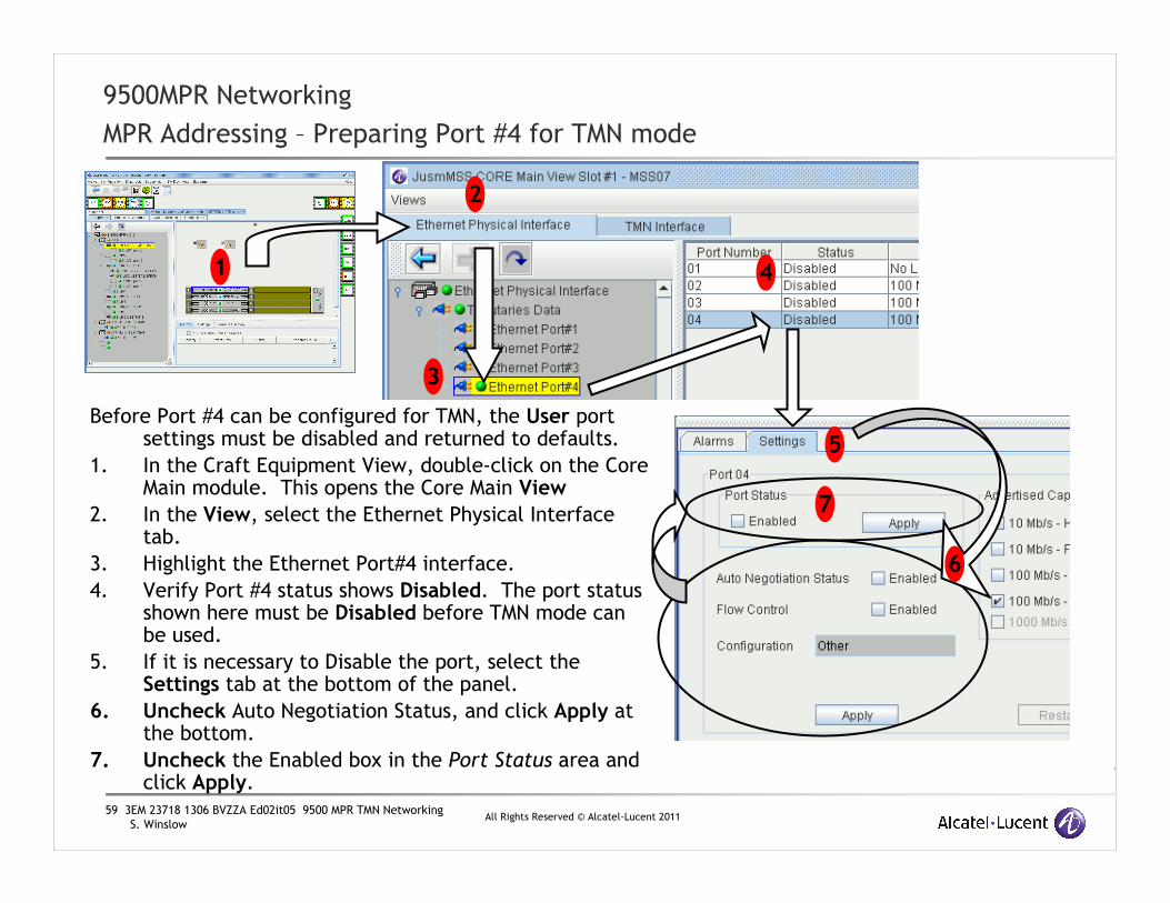
MPR Addressing – Preparing Port #4 for TMN mode
Before Port #4 can be configured for TMN, the User port settings must be disabled and returned to defaults.
1. In the Craft Equipment View, double-click on the Core Main module. This opens the Core Main View
2. In the View, select the Ethernet Physical Interface tab.
3. Highlight the Ethernet Port#4 interface.
4. Verify Port #4 status shows Disabled. The port status shown here must be Disabled before TMN mode can be used.
5. If it is necessary to Disable the port, select the Settings tab at the bottom of the panel.
6. Uncheck Auto Negotiation Status, and click Apply at the bottom.
7. Uncheck the Enabled box in the Port Status area and click Apply.
1
2
3
5
4
7
6

60 3EM 23718 1306 BVZZA Ed02it05 9500 MPR TMN Networking
S. WinslowAll Rights Reserved © Alcatel-Lucent 2011
9500MPR Networking
MPR Addressing – Configuring the MPT RF PPPoE Links
For MPT-HL RF PPPoE interfaces:
1. In the Craft Equipment View double-click on the P8ETH EAS Board. This opens the EAS Main View.
2. In the View panel select the desired MPT-HL Port
3. Click on the Settings Tab
4. In the PPP RF area Enable the interface and configure as needed. No IP Address is assigned, the Local Address will be used.
5. Click on Apply
6. After both ends of the link have been configured and the link comes up, the detected far end MPR Local Address will show in the Remote Address box.
1
2
3
4
5
6

61 3EM 23718 1306 BVZZA Ed02it05 9500 MPR TMN Networking
S. WinslowAll Rights Reserved © Alcatel-Lucent 2011
9500MPR Networking
MPR Addressing – Configuring the ODU300 RF PPPoE Links
For ODU300 RF PPP interfaces:
1. In the Craft Equipment View double-click on the MD300 Board. This opens the Radio Main View.
2. In the View panel click on the Settings Tab
3. Click on the sub-panel resize arrows to expand the PPP RF area.
4. In the PPP RF area Enable the interface and configure as needed. No IP Address needs to be assigned, the Local Address will be used.
5. Click on Apply
6. After both ends of the link have been configured and the link comes up, the detected far end MPR Local Address will show in the Remote Address box.
1
2
3
4
5
6

62 3EM 23718 1306 BVZZA Ed02it05 9500 MPR TMN Networking
S. WinslowAll Rights Reserved © Alcatel-Lucent 2011
9500MPR Networking
MPR Addressing – Configuring the TMN In-Band Interfaces in A-R2.02.xx
The TMN In-Band interfaces:
1. Core ports to be used for TMN In-Band must be activated before using. In the Craft Equipment View, double-click on the Core Main module. This opens the Core Main View
2. In the Equipment View, select the Ethernet Physical Interface tab.
3. Select Port #3 or Port #5 interfaces and enable as asneeded.
4. To change the parameters, select the Settings tab at the bottom of the panel, check Enabled and Apply
5. Open a Web Browser to the MPR address and log in. From the Main Menu, select the ‘Inband TMN’option.
6. Fill in the TMN In-Band network parameters and VLAN Id and Click on Enable. The OSPF ID is optional and will default to 0.
1
5
2
3
4

63 3EM 23718 1306 BVZZA Ed02it05 9500 MPR TMN Networking
S. WinslowAll Rights Reserved © Alcatel-Lucent 2011
9500MPR Networking
MPR Addressing – Configuring the TMN In-Band Interfaces in R03.00.00 and later
The TMN In-Band interfaces:
1. In the Craft Equipment View, double-click on the Core Main module. This opens the Core Main View
2. In the View, select the TMN Interface tab. Current interface settings are shown on the right side of the panel
3. Highlight a TMN In-Band interface to configure.
4. To change the parameters, select the Settings tab at the bottom of the panel. Parameters unique to the TMN In-Band interfaces are the VLAN ID and the Associated Ethernet Ports. Note the highlighted ports.
5. Click on Apply.
1
2
3
4
5
64 3EM 23718 1306 BVZZA Ed02it05 9500 MPR TMN Networking
S. WinslowAll Rights Reserved © Alcatel-Lucent 2011
9500MPR Networking
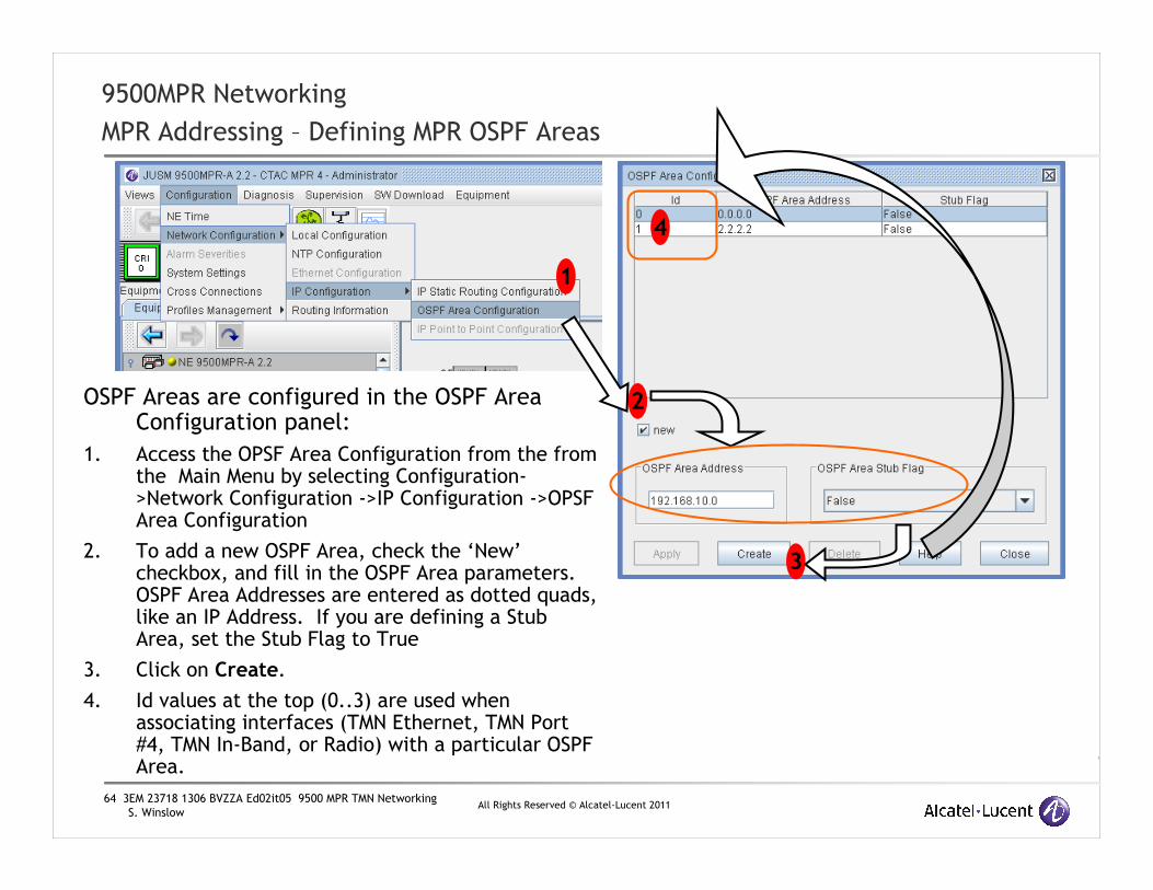
MPR Addressing – Defining MPR OSPF Areas
OSPF Areas are configured in the OSPF Area Configuration panel:
1. Access the OPSF Area Configuration from the from the Main Menu by selecting Configuration->Network Configuration ->IP Configuration ->OPSF Area Configuration
2. To add a new OSPF Area, check the ‘New’checkbox, and fill in the OSPF Area parameters. OSPF Area Addresses are entered as dotted quads, like an IP Address. If you are defining a Stub Area, set the Stub Flag to True
3. Click on Create.
4. Id values at the top (0..3) are used when associating interfaces (TMN Ethernet, TMN Port #4, TMN In-Band, or Radio) with a particular OSPF Area.
1
2
3
4

65 3EM 23718 1306 BVZZA Ed02it05 9500 MPR TMN Networking
S. WinslowAll Rights Reserved © Alcatel-Lucent 2011
www.alcatel-lucent.comwww.alcatel-lucent.com

66 3EM 23718 1306 BVZZA Ed02it05 9500 MPR TMN Networking
S. WinslowAll Rights Reserved © Alcatel-Lucent 2011
A9500MPR TMN Networking Appendix
Basics of IP Addressing

67 3EM 23718 1306 BVZZA Ed02it05 9500 MPR TMN Networking
S. WinslowAll Rights Reserved © Alcatel-Lucent 2011
9500MPR TMN Networking
IP Addressing Primer – Addressing Standards
There are two types of IP addressing schemes:
•IPv4 - Internet Protocol version 4
•Most widely used addressing type
•IPv6 - Internet Protocol version 6
•Replacement for IPv4Authority : IANA - Internet Assigned Number Authorityhttp://www.iana.org
The 9500MPR TMN Management interfaces only support
IPv4 addressing

68 3EM 23718 1306 BVZZA Ed02it05 9500 MPR TMN Networking
S. WinslowAll Rights Reserved © Alcatel-Lucent 2011
9500MPR TMN Networking
IP Addressing Primer – IPv4 Addresses
IPv4 ADDRESS
IPv4 addresses are a 32 bit binary number:
1010 1100 0001 0110 1000 1010 1100 1111
The most common representation uses dotted decimal
notation such as:
172.22.138.207
Each of the four decimal numbers represents 8 bits of the
32 bit address. This means each of the four numbers can
range from 0 to 255.

69 3EM 23718 1306 BVZZA Ed02it05 9500 MPR TMN Networking
S. WinslowAll Rights Reserved © Alcatel-Lucent 2011
9500MPR TMN Networking
IP Addressing Primer – IP Address parameters
The 32 bit IP addresses are divided into a Network prefix and a Host number. This
particular example shows a 22 bits allocated for the network prefix and 10 bits for the
host number:
172.22.138.207 -> 1010 1100 0001 0110 1000 1010 1100 1111
network prefix host number
There are two numbers reserved in each network, the first number and the last
number. When the Host number portion of an IP address is all zeros it is called the
Network Number. This is the first number in a Network:
1010 1100 0001 0110 1000 1000 0000 0000 -> 172.22.136.0
network prefix host number
When the Host number portion of an IP address is all ones it is called a Broadcast
Address. This is the last number in a Network:
1010 1100 0001 0110 1000 1011 1111 1111 -> 172.22.139.255
network prefix host number

70 3EM 23718 1306 BVZZA Ed02it05 9500 MPR TMN Networking
S. WinslowAll Rights Reserved © Alcatel-Lucent 2011
9500MPR TMN Networking
IP Addressing Primer – The Netmask
Netmasks consists of:
�a contiguous string of ones at the more significant end for the Network prefix portion
�a contiguous string of zeros at the less significant end for the Host number portion
�No intervening bits
The division between the network prefix and host number in an IP Address is specified using a Netmask. Like IP Addresses, Netmasks are 32 bit numbers and the usual representation is four dotted decimal numbers. Netmasks define the size or the number of hosts within a network.
HEX BIN DEC
00 0000 0000 0
80 1000 0000 128
C0 1100 0000 192
E0 1110 0000 224
F0 1111 0000 240
F8 1111 1000 248
FC 1111 1100 252
FE 1111 1110 254
FF 1111 1111 255
Table 1Acceptable mask valuesUsing the example address from before with a 22 bit network
prefix, the corresponding netmask is shown:
172.22.138.207 -> 1010 1100 . 0001 0110 . 1000 1010 . 1100 1111
network prefix host number
255.255.252.0 -> 1111 1111 . 1111 1111 . 1111 1100 . 0000 0000
The MPR supports recommendations in RFC1812 section 2.2.5.2: Net Mask Requirements for Classless Inter Domain Routing(CIDR) which allows the boundary between the network and host portions to be defined in 1 bit increments. The table to the right shows allowed values.

71 3EM 23718 1306 BVZZA Ed02it05 9500 MPR TMN Networking
S. WinslowAll Rights Reserved © Alcatel-Lucent 2011
9500MPR TMN Networking
IP Addressing Primer – Derivation of related network parameters
Netmask are utilized for ease of hardware computation of related Network parameters.
A logical “AND” of the Netmask and Address gives the Network Number.
A logical “OR” of the Address with the inverse of the Netmask gives the Broadcast Address.
For example:
If my address were 10.100.49.30 and my netmask was 255.255.254.0 then I am a member of network 10.100.48.0, and my broadcast address is 10.100.49.255
10.100.49.30 -> 0000 1010 . 0110 0100 . 0011 0001 . 0001 1110 IP Address255.255.254.0 -> 1111 1111 . 1111 1111 . 1111 1110 . 0000 0000 Netmask
---------------------------------------------Logical AND 0000 1010 . 0110 0100 . 0011 0000 . 0 000 0000 -> 10.100.48.0 Network
10.100.49.30 -> 0000 1010 . 0110 0100 . 0011 0001 . 0001 1110 IP Address255.255.254.0 -> 0000 0000 . 0000 0000 . 0000 0001 . 1111 1111 Inverted Netmask
---------------------------------------------Logical OR 0000 1010 . 0110 0100 . 0011 0001 . 1 111 1111 -> 10.100.49.255 Broadcast
72 3EM 23718 1306 BVZZA Ed02it05 9500 MPR TMN Networking
S. WinslowAll Rights Reserved © Alcatel-Lucent 2011
9500MPR TMN Networking
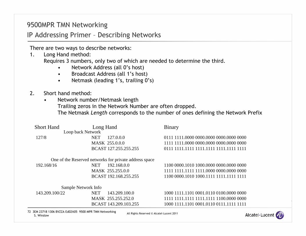
IP Addressing Primer – Describing Networks
There are two ways to describe networks:
1. Long Hand method:
Requires 3 numbers, only two of which are needed to determine the third.
• Network Address (all 0’s host)
• Broadcast Address (all 1’s host)
• Netmask (leading 1’s, trailing 0’s)
2. Short hand method:
• Network number/Netmask length
Trailing zeros in the Network Number are often dropped.
The Netmask Length corresponds to the number of ones defining the Network Prefix
Loop back Network127/8 NET 127.0.0.0
MASK 255.0.0.0 BCAST 127.255.255.255
One of the Reserved networks for private address space192.168/16 NET 192.168.0.0
MASK 255.255.0.0BCAST 192.168.255.255
Sample Network Info143.209.100/22 NET 143.209.100.0
MASK 255.255.252.0BCAST 143.209.103.255
Short Hand Long Hand
0111 1111.0000 0000.0000 0000.0000 00001111 1111.0000 0000.0000 0000.0000 00000111 1111.1111 1111.1111 1111.1111 1111
1100 0000.1010 1000.0000 0000.0000 00001111 1111.1111 1111.0000 0000.0000 00001100 0000.1010 1000.1111 1111.1111 1111
1000 1111.1101 0001.0110 0100.0000 00001111 1111.1111 1111.1111 1100.0000 00001000 1111.1101 0001.0110 0111.1111 1111
Binary

73 3EM 23718 1306 BVZZA Ed02it05 9500 MPR TMN Networking
S. WinslowAll Rights Reserved © Alcatel-Lucent 2011
9500MPR TMN Networking
IP Addressing Primer – Possible Network Sizes
Two hosts are reserved in any Ethernet network for the Network Number, and the Broadcast
address: the all 0’s host and the all 1’s host respectively. This means the number of useable
hosts is always two less than the total number of addresses in the network. The smallest
Broadcast Ethernet network with useable address space is highlighted in RED.
Table 2Network bits host bits useable hosts Decimal mask
31 1 0 255.255.255.254
30 2 2 255.255.255.25229 3 6 255.255.255.24828 4 14 255.255.255.240 27 5 30 255.255.255.22426 6 62 255.255.255.19225 7 126 255.255.255.12824 8 254 255.255.255.023 9 510 255.255.254.022 10 1022 255.255.252.021 11 2046 255.255.248.020 12 4094 255.255.240.019 13 8190 255.255.224.018 14 16382 255.255.192.017 15 32766 255.255.128.016 16 65534 255.255.0.0
… … … …

74 3EM 23718 1306 BVZZA Ed02it05 9500 MPR TMN Networking
S. WinslowAll Rights Reserved © Alcatel-Lucent 2011
9500MPR TMN Networking
IP Addressing Primer – Subnet Calculators
Calculating network parameters can be difficult for those not familiar with the process.
The are various online Network subnet calculators available that make derivation of all the related numbers relatively easy.
Here are links to two such tools:
http://www.subnetmask.info/
http://www.subnet-calculator.com/

75 3EM 23718 1306 BVZZA Ed02it05 9500 MPR TMN Networking
S. WinslowAll Rights Reserved © Alcatel-Lucent 2011
B9500MPR TMN Networking Appendix
Basic Networking Concepts
76 3EM 23718 1306 BVZZA Ed02it05 9500 MPR TMN Networking
S. WinslowAll Rights Reserved © Alcatel-Lucent 2011
9500MPR TMN Networking
Basic Networking Concepts - Communication within a Network
Network
Computer 1 Computer 2
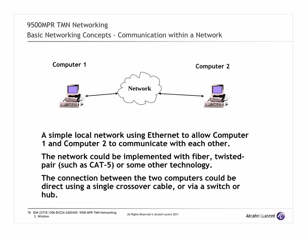
A simple local network using Ethernet to allow Computer 1 and Computer 2 to communicate with each other.
The network could be implemented with fiber, twisted-pair (such as CAT-5) or some other technology.
The connection between the two computers could be direct using a single crossover cable, or via a switch or hub.

77 3EM 23718 1306 BVZZA Ed02it05 9500 MPR TMN Networking
S. WinslowAll Rights Reserved © Alcatel-Lucent 2011
9500MPR TMN Networking
Basic Networking Concepts - Communication within a Network
Network
Computer 1
00:C0:F8:34:19:C0
Computer 2
00:F8:62:CF:8A:B3
So how do two devices communicate using Ethernet?
A physical address is used to distinguish the two devices. This address is often referred to as the MAC address, but is sometimes referred to as the hardware address or the Ethernet address. The MAC address is a 48 bit address assigned by the manufacturer of the network interface before it is shipped, it is designed to be unique, and is used to help identify a machine on a network.

78 3EM 23718 1306 BVZZA Ed02it05 9500 MPR TMN Networking
S. WinslowAll Rights Reserved © Alcatel-Lucent 2011
9500MPR TMN Networking
Basic Networking Concepts - Communication within a Network
Network
Computer 1
10.0.0.1
Computer 2
10.0.0.2
MAC addressing is OK for direct Ethernet communication, but:
• the end user has no control over the address
• it is impractical outside a local network.
To make things easier for users, another communication layer is added:
•IP Addressing

79 3EM 23718 1306 BVZZA Ed02it05 9500 MPR TMN Networking
S. WinslowAll Rights Reserved © Alcatel-Lucent 2011
9500MPR TMN Networking
Basic Networking Concepts - Communication within a Network
Network
Computer 1
10.0.0.1Computer 2
10.0.0.2
Even with IP Addressing, any time one device needs to talk with another using Ethernet, it still needs to know the MAC address for that device.
This is normally resolved using a broadcast that queries every system on the local network asking the device you are trying to communicate with to send back its MAC address.
This process is handled in TCP/IP by Address Resolution Protocol (ARP)
Who has 10.0.0.2?
I’m at 00:C0:DF:48:F3:47

80 3EM 23718 1306 BVZZA Ed02it05 9500 MPR TMN Networking
S. WinslowAll Rights Reserved © Alcatel-Lucent 2011
9500MPR TMN Networking
Basic Network Concepts – TCP Stack
SNMP ManagerLayer 5
SNMP Agent
TCP, UDP PacketsLayer 4
IP DatagramLayer 3
Ethernet FramesLayer 2
Copper, Fiber, etcLayer 1
Application Layer
Transport Layer
Network Layer
Data Link Layer
Physical Network
Sender Receiver
Application Layer
Transport Layer
Network Layer
Data Link Layer
Physical Network
Virtual
Connection
Physical
Connection
So how do the addressing methods fit together?
IP Addresses used at this layer
MAC Addresses used at this layer
•MAC addresses are used at Layer 2
•IP Addresses are used at Layer 3

81 3EM 23718 1306 BVZZA Ed02it05 9500 MPR TMN Networking
S. WinslowAll Rights Reserved © Alcatel-Lucent 2011
9500MPR TMN Networking
Basic Networking Concepts – Connecting Networks
Network A
Computer 1
Computer 2
Network B
Computer 3
Computer 4
In this situation we have two isolated networks. Computer 1 cancommunicate with Computer 2, and Computer 3 can communicate withComputer 4.
But what if Computer 1 needs to send a message to Computer 4?
We need a way to interface the two Networks.

82 3EM 23718 1306 BVZZA Ed02it05 9500 MPR TMN Networking
S. WinslowAll Rights Reserved © Alcatel-Lucent 2011
9500MPR TMN Networking
Basic Networking Concepts - Router and Bridge Comparison
There are two common ways to connect networks together
Layer 3
Layer 2
Layer 1
Sender ReceiverApplication Layer
Transport Layer
Network Layer
Data Link Layer
Physical Network
Virtual
Connection
Physical
Connection
Application Layer
Transport Layer
Network Layer
Data Link Layer
Physical Network
Data Link Layer
Physical Network
Data Link Layer
Physical Network
Physical
Connection
Network Layer
Network Layer
Bridge
Router
Bridges connect at Layer 2
Routers connect at Layer 3

83 3EM 23718 1306 BVZZA Ed02it05 9500 MPR TMN Networking
S. WinslowAll Rights Reserved © Alcatel-Lucent 2011
9500MPR TMN Networking
Basic Networking Concepts – Connecting Networks
Network A
Computer 1
10.0.0.1
Computer 2
10.0.0.2
Network B
Computer 3
10.0.0.3
Computer 4
10.0.0.4
The common Ethernet Switch is a form of bridge. The interfaces on a bridge have no IP address. Bridges are convenient when all network devices share the same address space. Packets received at one port are essentially repeated on the other port(s). Most current bridges are somewhat smarter about which packets they forward and where, but that’s beyond the scope of this presentation.
The 9500MPR TMN Network is not bridged between TMN Ports or across RF Links!
Switch

84 3EM 23718 1306 BVZZA Ed02it05 9500 MPR TMN Networking
S. WinslowAll Rights Reserved © Alcatel-Lucent 2011
9500MPR TMN Networking
Basic Networking Concepts – Connecting Networks
Network ANetwork B
Routers are another way to connect two networks together. Routers are used when the two networks use different addressing space.
Unlike bridges, interfaces on a router need an address within the networks they are attached to. The interface IP address of a router is a ‘gateway’ to other networks. Most network devices are configured to use a nearby router as a Default Gateway.
Router
Computer 1
IP 172.22.64.1Gateway 172.22.64.38
Computer 2
IP 172.22.64.2Gateway 172.22.64.38
Computer 4
IP 192.168.10.4Gateway 192.168.10.137
Interface172.22.64.38
Interface192.168.10.137
Computer 3
IP 192.168.10.3Gateway 192.168.10.137

85 3EM 23718 1306 BVZZA Ed02it05 9500 MPR TMN Networking
S. WinslowAll Rights Reserved © Alcatel-Lucent 2011
9500MPR TMN Networking
Basic Networking Concepts - Routers
�A Router with multiple interfaces can also be used to divide address space into smaller networks. This process of division can be repeated to get the desired network size, optimizing use of the available address space. Each division is called a sub-network.
�In the above example, the original 192.168.64.0/16 network at the top left is divided into four subnets by increasing the length of the netmask for the new subnets from 16 to 18 bits. Three of the new subnets are directly attached to Router A. One /18 subnet has been further divided into four /20 subnets using Router B. Router B has an interface within the 192.168.0.0/18 network.
�Router A doesn’t need to know that Router B has divided the 192.168.64.0/18 network into subnets, it only needs to know that the 192.168.64.0/18 aggregate address space is accessible via Router B.
External Network
192.168.0.0/1665534 addresses
Router
External Network 192.168.0.0/18
16346 addressesRouterA
192.168.128.0/1816346 addresses
192.168.192.0/1816346 addresses
192.168.0.0/204094 addresses
192.168.16.0/204094 addresses
Router B
192.168.32.0/204094 addresses
192.168.48.0/204096 addresses
192.168.64.0/18 Address Range
192.168.0.1
192.168.0.35

86 3EM 23718 1306 BVZZA Ed02it05 9500 MPR TMN Networking
S. WinslowAll Rights Reserved © Alcatel-Lucent 2011
9500MPR TMN Networking
Route Configuration
External Networks
RouterA
192.168.0.0/1816346 addresses
RouterB
I know how to reach addresses in the space:
192.168.64.0/18Use my gateway at:
192.168.0.35
Use me for yourDefault Route
My gateway is at: 192.168.0.1
� There are several Dynamic Routing Protocols. The protocol used by the 9500 MPR is called OSPF (Open Shortest Path First)
In the Previous slide, Router A needs to know that addresses in the 192.168.64.0/18 network can be reached by using Router B as a gateway.
There are two methods considered:
1. Static Routing where all routes are manually provisioned.
2. Dynamic Routing where routers exchange route information using a Dynamic Routing Protocol. The Dynamic routing message exchange is depicted below:
192.168.0.0/204094 addresses
192.168.16.0/204094 addresses
192.168.32.0/204094 addresses
192.168.48.0/204096 addresses

87 3EM 23718 1306 BVZZA Ed02it05 9500 MPR TMN Networking
S. WinslowAll Rights Reserved © Alcatel-Lucent 2011
C9500MPR TMN Networking Appendix
DHCP
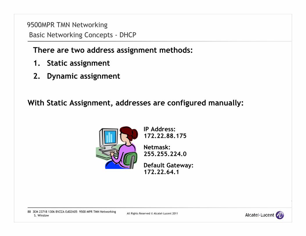
88 3EM 23718 1306 BVZZA Ed02it05 9500 MPR TMN Networking
S. WinslowAll Rights Reserved © Alcatel-Lucent 2011
9500MPR TMN Networking
Basic Networking Concepts - DHCP
There are two address assignment methods:
1. Static assignment
2. Dynamic assignment
IP Address: 172.22.88.175
Netmask: 255.255.224.0
Default Gateway: 172.22.64.1
With Static Assignment, addresses are configured manually:

89 3EM 23718 1306 BVZZA Ed02it05 9500 MPR TMN Networking
S. WinslowAll Rights Reserved © Alcatel-Lucent 2011
9500MPR TMN Networking
Basic Networking Concepts - Address Assignment
Network
With Dynamic Addressing, equipment on a network is configured using the Dynamic Host Configuration Protocol (DHCP) as documented in RFC2131.
The 9500MPR provides a simple DCHP server on the TMN Ethernet port for configuring Craft computers. This server is enabled by Default.
With DCHP, when clients connect to a network, they send a broadcast asking if there is a server that can provide networking configuration.
If a DHCP Server is available, the client can then request its network configuration parameters.
When a DHCP Server provides an IP Address to a client it is called a Lease. The typical parameters provided usually include: IP Address, Netmask, Default Gateway, and Lease Timeout.
Hello! I’d like to configure my network
interface.
I offer to configure your network.
DHCPServer

90 3EM 23718 1306 BVZZA Ed02it05 9500 MPR TMN Networking
S. WinslowAll Rights Reserved © Alcatel-Lucent 2011
9500MPR TMN Networking
Basic Networking Concepts - Address Assignment
•The DHCP Server is responsible for keeping track of which IP Addresses are currently Leased and not hand out duplicates.
•When a client is finished with an IP address, it is supposed to inform the Server the address is no longer needed. The Server will then mark the address as available for reuse.
•Leases have an associated timeout specified by the server. The Lease timeout is part of the configuration parameter message. This timeout is the maximum time the client is allowed to use the IP Address. Timeouts are specified in seconds and usually range from minutes to days.
•If a client disconnects without informing the server or otherwise fails to renew the Lease, then when the timeout arrives, the Server will mark the address as available for reuse.
•If a client needs an IP Address for an extended period, it must negotiate with the DHCP server to renew the Lease prior to timeout. If the Lease expires, the client must request a new Lease and may be assigned a different IP Address.

91 3EM 23718 1306 BVZZA Ed02it05 9500 MPR TMN Networking
S. WinslowAll Rights Reserved © Alcatel-Lucent 2011
9500MPR TMN Networking
Basic Networking Concepts - Address Assignment
•DHCP is based on the Bootstrap Protocol RFC951(BOOTP)
�DHCP can be relayed between networks by a BOOTP Relay Agent. These are sometimes called DHCP Relay Agents.
�A BOOTP Relay allows DHCP clients and servers to be in different Networks.
�BOOTP Relay Agents can be incorporated into routers.
�The 9500MPR TMN Network router does NOT Relay DHCP or BOOTP messages.

92 3EM 23718 1306 BVZZA Ed02it05 9500 MPR TMN Networking
S. WinslowAll Rights Reserved © Alcatel-Lucent 2011
9500MPR TMN Networking
Basic Networking Concepts - Address Assignment
• Multiple DHCP Servers on a Network:
1) This is possible provided either:
• The multiple DHCP Servers share a common Lease database so they do not serve duplicate addresses
or
• The Servers are configured to offer Leases from non-overlapping address ranges.
2) When a client broadcasts a request looking for a DHCP server andmultiple servers respond, the client chooses which server it will use for configuration. Frequently this is the first server to respond, but this behavior is not required.
Note: The 9500MPR DHCP server Leases addresses based on a very specific set of rules. These rules, defined on the following pages, are not user configurable.
The 9500MPR DHCP server must be disabled before connecting the TMN Ethernet interface to an external network controlled by another DHCP server otherwise conflicts will occur including possible loss of connectivity in the external network!

93 3EM 23718 1306 BVZZA Ed02it05 9500 MPR TMN Networking
S. WinslowAll Rights Reserved © Alcatel-Lucent 2011
9500MPR TMN Networking
MPR Addressing – DHCP: 9500MPR DHCP Address Assignment Behavior
For simplicity, the built-in DHCP server in the 9500MPR operates using a fixed set of rules. This fixed behavior puts restrictions on the way addresses in the TMN Ethernet Port subnet can be used whenever the DHCP server is enabled.
1. The DHCP Server uses an address pool based on the TMN Ethernet IP address and subnet.
2. A maximum of 10 addresses are reserved for Leases in the following manner:
a) If the TMN Ethernet Port address is the first address in the subnet, reserve addresses immediately above the Port to the end of the subnet or a maximum of 10 addresses, whichever comes first.
b) If the TMN Ethernet Port address is NOT the first address of the subnet but there are 10 IP addresses above it before the end of the subnet reserve those 10 addresses for the DHCP pool.
c) If the TMN Ethernet Port address is NOT the first address in the subnet, and there are fewer than 10 addresses above it before the end of the subnet then reserve addresses immediately prior to the port up to a maximum of 10 addresses or the start of the subnet whichever comes first.
NOTE: This behavior is different from that described in older documents where the pool was based on whether the TMN Ethernet IP address was located in the upper or lower half of the subnet.
If the MPR DHCP Server is enabled, the addresses reserved for Leases should not be statically assigned to other equipment.
The manner in which DHCP addresses are reserved and assigned by the MPR is depicted in the examples on the following slides.

94 3EM 23718 1306 BVZZA Ed02it05 9500 MPR TMN Networking
S. WinslowAll Rights Reserved © Alcatel-Lucent 2011
9500MPR TMN Networking
MPR Addressing – DHCP: 9500MPR DHCP Address Assignment Behavior
Network (/28)192.168.1.0
192.168.1.1
192.168.1.2
TMN Ethernet Port192.168.1.3
DHCP Assigned 1192.168.1.4
DHCP Assigned 2192.168.1.5
DHCP Assigned 3192.168.1.6
DHCP Assigned 4192.168.1.7
DHCP Assigned 5192.168.1.8
DHCP Assigned 6192.168.1.9
DHCP Assigned 7192.168.1.10
DHCP Assigned 8192.168.1.11
DHCP Assigned 9192.168.1.12
DHCP Assigned 10192.168.1.13
192.168.1.14
Broadcast192.168.1.15
EquipmentIP Addr
Network (/28)192.168.1.0
192.168.1.1
DHCP Assigned 1192.168.1.2
DHCP Assigned 2192.168.1.3
DHCP Assigned 3192.168.1.4
DHCP Assigned 4192.168.1.5
DHCP Assigned 5192.168.1.6
DHCP Assigned 6192.168.1.7
DHCP Assigned 7192.168.1.8
DHCP Assigned 8192.168.1.9
DHCP Assigned 9192.168.1.10
DHCP Assigned 10192.168.1.11
TMN Ethernet Port192.168.1.12
192.168.1.13
192.168.1.14
Broadcast192.168.1.15
EquipmentIP Addr
In Table 1, there are 10 addresses available above the TMN Ethernet Port address and they are reserved for the DHCP address pool (Rule 2b). Addresses not used by the TMN Ethernet Port or reserved for DHCP Leases can be statically assigned to other equipment.
In Table 2, there are fewer than 10 addresses available above the TMN Ethernet Port, but there are 10 available below it and they are reserved for the DHCP address pool (Rule 2c). Addresses not used by the TMN Ethernet Port or reserved for DHCP Leases can be statically assigned to other equipment.
Table 1 Table 2

95 3EM 23718 1306 BVZZA Ed02it05 9500 MPR TMN Networking
S. WinslowAll Rights Reserved © Alcatel-Lucent 2011
9500MPR TMN Networking
MPR Addressing – DHCP: 9500MPR DHCP Address Assignment Behavior
Network (/29)192.168.1.0
TMN Ethernet Port192.168.1.1
DHCP Assigned 1192.168.1.2
DHCP Assigned 2192.168.1.3
DHCP Assigned 3192.168.1.4
DHCP Assigned 4192.168.1.5
DHCP Assigned 5192.168.1.6
Broadcast192.168.1.7
EquipmentIP Addr
Network (/29)192.168.1.0
DHCP Assigned 1192.168.1.1
DHCP Assigned 2192.168.1.2
DHCP Assigned 3192.168.1.3
DHCP Assigned 4192.168.1.4
TMN Ethernet Port192.168.1.5
192.168.1.6
Broadcast192.168.1.7
EquipmentIP Addr
In Table 3, the TMN Ethernet Port address is the first address in the subnet so addresses above the port will be reserved. Since there are fewer than 10 addresses to the end of the subnet all are reserved for the DHCP address pool (Rule 2a). This leaves NO addresses available for static assignment to other equipment.
In Tables 4 and 5, the TMN Ethernet Port address is not the first address in the subnet and there are fewer than 10 addresses available above the port so addresses below the port will be reserved. With fewer than 10 addresses available below the port all are reserved for the DHCP address pool (Rule 2c). Addresses not used by the TMN Ethernet Port or reserved for DHCP Leases can be statically assigned to other equipment.
Table 3 Table 4
Network (/29)192.168.1.0
DHCP Assigned 1192.168.1.1
TMN Ethernet Port192.168.1.2
192.168.1.3
192.168.1.4
192.168.1.5
192.168.1.6
Broadcast192.168.1.7
EquipmentIP Addr
Table 5

96 3EM 23718 1306 BVZZA Ed02it05 9500 MPR TMN Networking
S. WinslowAll Rights Reserved © Alcatel-Lucent 2011
D9500MPR TMN Networking Appendix
OSPF

97 3EM 23718 1306 BVZZA Ed02it05 9500 MPR TMN Networking
S. WinslowAll Rights Reserved © Alcatel-Lucent 2011
9500MPR TMN Networking
Network Services – OSPF Overview
� Open Shortest Path First (OSPF) is the dynamic routing protocol used with the 9500MPR. It is defined in RFC 2328.
� OSPF is a link-state protocol. We can think of a link as an interface to a router, and the associated link state as a description of that interface and it’s relation to other routers. The link state includes such info as:
• IP Address of the interface
• Netmask
• The type of network
• The routers connected to that interface
� A collection of these link-states for several interfaces would form a link-state database

98 3EM 23718 1306 BVZZA Ed02it05 9500 MPR TMN Networking
S. WinslowAll Rights Reserved © Alcatel-Lucent 2011
9500MPR TMN Networking
Network Services – OSPF Overview
� Routers running OSPF advertise their link state to neighboring routers at initialization and again whenever any link state information changes. The advertisement represents the collection of all link states on that router.
� Routers exchange link states by means of flooding. Whenever a router receives a link state update, it stores a copy in it’s local database and propagates the update to other routers.
� After the database is updated, the router will calculate the Shortest Path Tree to all destinations. The destinations, the cost, and the next hop to reach those destinations form the IP routing table.
� To control the flooding of link state updates, OSPF uses Areas. All routers within an Area have the same link state database.

99 3EM 23718 1306 BVZZA Ed02it05 9500 MPR TMN Networking
S. WinslowAll Rights Reserved © Alcatel-Lucent 2011
9500MPR TMN Networking
Network Services – OSPF Overview
� Routers that have all of their interfaces in the same area are called Internal Routers.
� Routers that belong to one or more areas and connect to the backbone must keep a link state database for all attached areas plus the Backbone Area. These routers are called Area Border Routers (ABR)
� A router that act as a gateway between OSPF and another routing protocol (including Static routes) is called an Autonomous System Boundary Router (ASBR).
Static
Autonomous System Boundary Router (ASBR)
Area Border Router (ABR)
InternalRouters
R ExternalRouter
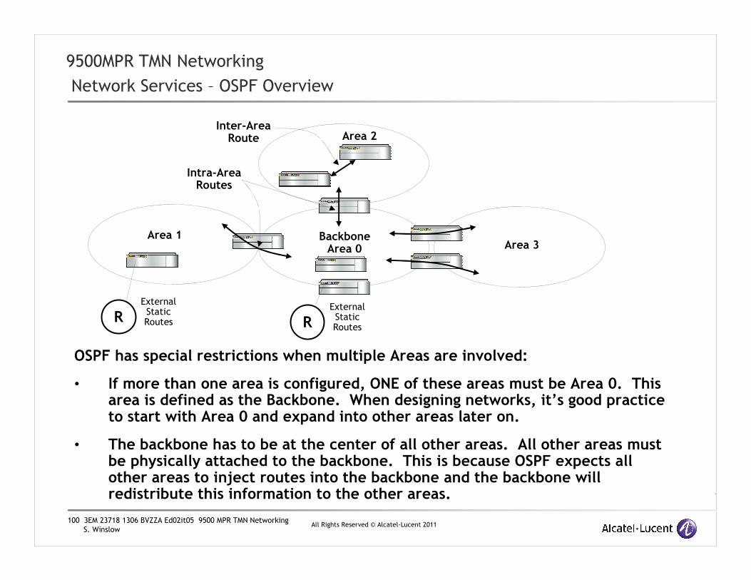
100 3EM 23718 1306 BVZZA Ed02it05 9500 MPR TMN Networking
S. WinslowAll Rights Reserved © Alcatel-Lucent 2011
9500MPR TMN Networking
Network Services – OSPF Overview
OSPF has special restrictions when multiple Areas are involved:
• If more than one area is configured, ONE of these areas must be Area 0. This area is defined as the Backbone. When designing networks, it’s good practice to start with Area 0 and expand into other areas later on.
• The backbone has to be at the center of all other areas. All other areas must be physically attached to the backbone. This is because OSPF expects all other areas to inject routes into the backbone and the backbone will redistribute this information to the other areas.
R
Backbone Area 0
Area 1
Area 2
Area 3
External StaticRoutes
Inter-Area Route
Intra-Area Routes
RExternal StaticRoutes

101 3EM 23718 1306 BVZZA Ed02it05 9500 MPR TMN Networking
S. WinslowAll Rights Reserved © Alcatel-Lucent 2011
9500MPR TMN Networking
Network Services - OSPF
Stub Areas:
• OSPF allows certain areas to be defined as Stub Areas. Routes to external networks, including those learned through other protocols are not allowed to be flooded into these areas. Routing from Stub areas to the outside world is based on a default route to the nearest ABR. Configuring an area as a Stub reduces the size of the routing database within the area.
• An area could be qualified as a Stub if there is a single exit point from the area or if routing to destinations outside the area do not need to take an optimal path. In the example above, Area 2 is shown as a Stub, Area 3 could be a candidate for a Stub.
• Stub areas can have more than one ABR but must not contain any ASBR.
• All routers within a Stub area must have the Stub Flag set.
R
Backbone Area 0
Area 1
Stub Area 2
Area 3
External StaticRoutes
R External StaticRoutes
ABR
ASBR
ASBR

102 3EM 23718 1306 BVZZA Ed02it05 9500 MPR TMN Networking
S. WinslowAll Rights Reserved © Alcatel-Lucent 2011
9500MPR TMN Networking
Network Services – OSPF
9500MPR OSPF Features
� OSPFv2
� RouterID (RID) is the same as the Local Address
� Router Priority fixed to 1.
� If you want any external routers to have priority configure them for a priority greater than 1.
� Able to function as an:
• Area Border Router (ABR)
• Autonomous System Border Router (ASBR) when Static routing is used
� Each 9500MPR NE Supports up to 3 non-zero user defined OSPF Areas, for a total of 4 Areas.
� Area 0 is always defined in each MPR and cannot be deleted. It does not have to be associated with any interface.
� Stub support - all interfaces in the Stub Area should have the Stub Flag set
� No provisions for creating Virtual Links
� Authentication is not supported.

103 3EM 23718 1306 BVZZA Ed02it05 9500 MPR TMN Networking
S. WinslowAll Rights Reserved © Alcatel-Lucent 2011
9500MPR TMN Networking
Network Services – OSPF
9500MPR OSPF Deployment Hints
� Recommended maximum of about 200 entries in the routing table including both Static and Dynamic entries.
• To estimate the size of the OSPF routing table use:
• 1 entry for each RF Direction from each MPR node.
• 1 entry for each active TMN In-Band interface subnet in each MPR (up to two)
• 1 entry for each active TMN Port #4 interface subnet in each MPR
• 1 entry for each active TMN Ethernet Interface subnet in each MPR
• 1 entry for each static route configured in each MPR
• 1 entry for each external route learned via OSPF.
• Flooding of extenal routes from an adjacent backbone (Area 0) into the MPR route tables can be restricted by provisioning the MPRs into a non-zero stub area or by configuring the MPRs as an Autonomous (isolated) OSPF network.
• Example: A typical repeater supporting two Radio directions, an active TMN Port #4 interface with a matching Local Address, and an active TMN Ethernet port will contributes 4 route entries to the OSPF routing table.
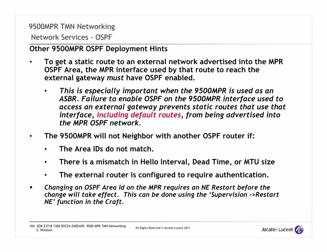
104 3EM 23718 1306 BVZZA Ed02it05 9500 MPR TMN Networking
S. WinslowAll Rights Reserved © Alcatel-Lucent 2011
9500MPR TMN Networking
Network Services - OSPF
Other 9500MPR OSPF Deployment Hints
• To get a static route to an external network advertised into the MPR OSPF Area, the MPR interface used by that route to reach the external gateway must have OSPF enabled.
• This is especially important when the 9500MPR is used as an ASBR. Failure to enable OSPF on the 9500MPR interface used to access an external gateway prevents static routes that use that interface, including default routes, from being advertised into the MPR OSPF network.
• The 9500MPR will not Neighbor with another OSPF router if:
• The Area IDs do not match.
• There is a mismatch in Hello Interval, Dead Time, or MTU size
• The external router is configured to require authentication.
� Changing an OSPF Area Id on the MPR requires an NE Restart before the change will take effect. This can be done using the ‘Supervision ->Restart NE’ function in the Craft.

105 3EM 23718 1306 BVZZA Ed02it05 9500 MPR TMN Networking
S. WinslowAll Rights Reserved © Alcatel-Lucent 2011
9500MPR TMN Networking
Network Services - OSPF
Other 9500MPR OSPF Fixed Parameters
When Neighboring with non-MPR external routers, it may be necessary to set several OSPF parameters on the external router to match the fixed values in the 9500MPR.
These parameters are:
� Hello Interval: 10 seconds
� Dead Time: 40 seconds
� MTU Size: 1500

106 3EM 23718 1306 BVZZA Ed02it05 9500 MPR TMN Networking
S. WinslowAll Rights Reserved © Alcatel-Lucent 2011
E9500MPR TMN Networking Appendix
Comparison to TMN Networking in the MDR-
8000

107 3EM 23718 1306 BVZZA Ed02it05 9500 MPR TMN Networking
S. WinslowAll Rights Reserved © Alcatel-Lucent 2011
9500MPR TMN Networking
Comparison of 9500MPR and MDR8000 TMN Networking
1) The MDR8000 TMN offers only one external Ethernet interface (feeding a 4 port switch). 2) The MDR8000 uses the same Local Address and TMN Ethernet address concept as the
9500MPR where Traps originate from the Local Address and the Local Address can be set the same as the TMN Ethernet address.
3) The MDR8000 TMN Craft port is a serial interface. The LLMAN utility is used to obtain a PPP connection through this interface in contrast to the Ethernet craft interface of the 9500MPR.
4) The MDR8000 TMN PPP interfaces: a) PPP Front Access interface b) Repeater PPP interface. c) RF PPP interface
These serial interfaces are functionally equivalent to the PPP RF links in a 9500 MPR network and serve the same purpose: providing a point to point connection to another NE. It's mainly a hardware interface difference not a networking difference.
4) The MDR8000 TMN supports RIPv1 and RIPv2 in addition to OSPF as dynamic routing protocols whereas the 9500MPR only supports OSPF.
5) The MDR8000 TMN offers no built-in mini-DCHP server. Use of the LLMAN utility and the serial Craft port allow direct NE connections with minimal user configuration.
6) MDR8000 TMN transport operates at 64kb/s in a dedicated out-of-band overhead channel. The 9500 MPR TMN transport uses an in-band dedicated VLAN at a relatively high priority supporting much higher transfer rates across the RF link.
7) The MDR8000 TMN supports a maximum of 250 entries in the routing table vs. approximately 200 for the 9500MPR. Despite the larger number of routing table entries, the practical number of MDR8000 NEs in an autonomous MDR8000 TMN Network is limited primarily by the slow transport channel and the number of hops (delay) to the farthest NE. The recommended maximum number of MDR8000 NEs in an autonomous TMN Network is around 30.
Otherwise, from a TMN Networking and Addressing standpoint, the two systems are equivalent.

108 3EM 23718 1306 BVZZA Ed02it05 9500 MPR TMN Networking
S. WinslowAll Rights Reserved © Alcatel-Lucent 2011
F9500MPR TMN Networking Appendix
MPR-e and MSS-1c Differences
109 3EM 23718 1306 BVZZA Ed02it05 9500 MPR TMN Networking
S. WinslowAll Rights Reserved © Alcatel-Lucent 2011
9500MPR TMN Networking
The MPRe and MPR-1c
The MPR-e and MSS-1c are compact components of the 9500 family of equipment. These units offer a subset of the full 9500MPR TMN features.
The following pages highlight the TMN differences and provide suggestions on TMN network deployment.

110 3EM 23718 1306 BVZZA Ed02it05 9500 MPR TMN Networking
S. WinslowAll Rights Reserved © Alcatel-Lucent 2011
9500MPR TMN Networking
MPRe and MPR1c Supported Interfaces
• The MPR-e and MSS-1c support fewer interfaces.
• The MPR-e supports one TMN In-Band VLAN interface and an RF-PPPoE link
• The MSS-1c supports:
• One TMN In-Band VLAN Interface
• Two TMN NMS interfaces for connecting to external networks
• One dedicated CT Connector for Local Craft connections
• An RF PPPoE link
RF PPPoETMN In-Band VLAN Interface
RRF PPPoETMN
In-Band VLAN Subnet
RRF-PPPoE
CT Connector
Subnet
TMN NMS2 Subnet
TMN NMS1 Subnet
TMN In-Band
VLAN Subnet
RF PPPoETMN In-Band VLAN Interface
CT Connector
NMS1
NMS2
MPR-e
MSS-1c
Dedicated Craft
Subnet
Only accessible with special
cable

111 3EM 23718 1306 BVZZA Ed02it05 9500 MPR TMN Networking
S. WinslowAll Rights Reserved © Alcatel-Lucent 2011
9500MPR TMN Networking
Differences between the 9500MPR and the MPR-e
MPRe:
1. The MPR-e does not support OSPF only static routing.
2. The MPR-e has a dedicated Craft interface that can only be accessed using a special cable. This interface is normally only used at initial NE turn-up and is not designed to be connected with an external network,only to a Craft computer. This dedicated interface is configured as a DHCP server with a fixed address and subnet. The DHCP server, NE address, and netmask are not configurable.
a) Fixed address: 192.168.30.1
b) Fixed netmask: 255.255.255.252
3. In service, all TMN network access is via the one TMN In-Band VLAN Interface. The VLAN Id is user configurable, but the interface is always associated with the MPR-e Traffic interface. Accessing the TMN In-Band interface requires that the external equipment be VLAN aware.

112 3EM 23718 1306 BVZZA Ed02it05 9500 MPR TMN Networking
S. WinslowAll Rights Reserved © Alcatel-Lucent 2011
9500MPR TMN Networking
Differences between the 9500MPR and the MPR-1c
MPR-1c:
1. The MSS-1c does not support OSPF only static routing.
2. The CT Connector port is a dedicated Craft interface. It is not designed to be connected with an external network, only to a Craft computer. The NE is configured on this interface as a DHCP server with a fixed address and subnet. The DHCP server, NE address and netmask are not configurable.
a) Fixed address: 192.168.30.1
b) Fixed netmask: 255.255.255.252
3. NMS1 and NMS2 ports are dedicated TMN ports. They function the same as the 9500MPR Port #4 in TMN Mode. If both NMS1 and NMS2 are enabled, they must be in different subnets.
4. One TMN In-Band interface is supported. It may be associated with the User Ethernet ports on the MSS-1c. The VLAN Id is user configurable. Accessing the TMN In-Band interface requires that the external equipment be VLAN aware.

113 3EM 23718 1306 BVZZA Ed02it05 9500 MPR TMN Networking
S. WinslowAll Rights Reserved © Alcatel-Lucent 2011
G9500MPR TMN Networking Appendix
Default Addresses
Reserved Addresses
TMN MTU

114 3EM 23718 1306 BVZZA Ed02it05 9500 MPR TMN Networking
S. WinslowAll Rights Reserved © Alcatel-Lucent 2011
9500MPR TMN Networking
Default 9500MPR NE Addressing
MSS-4/8 Shelf
• 10.0.1.2 NE Local Address
• 10.0.1.2/24 TMN Ethernet port
• 10.0.2.2/24 Port #4 in TMN Mode
• 10.0.3.2/24 TMN In-Band #1 in VLAN 1000
• 10.0.4.2/24 TMN In-Band #2 in VLAN 1001
9500MPR-e Standalone
• 10.0.1.2 NE Local Address
• 192.168.100.1/24 TMN In-Band in VLAN 4080
9500MPR-1c Shelf
• 192.168.30.1 NE Local Address (Fixed, not configurable)
• 192.168.30.1/30 TMN Ethernet Port (Fixed, not configurable)

115 3EM 23718 1306 BVZZA Ed02it05 9500 MPR TMN Networking
S. WinslowAll Rights Reserved © Alcatel-Lucent 2011
9500MPR TMN Networking
Reserved Addresses
The following address ranges are used internally by the 9500MPR. Addresses from the following ranges should not be assigned as a Local Address or used for an interface address.
9500MSS:
• 127.0.0.0/8 Loopback
• 100.1.0.0/24 Internal Core Main to Core Spare communications
• 100.1.0.1 Core Main
• 100.1.0.2 Core Spare
• 100.2.0.0/24 Internal MSS to MPT communications
• 100.2.0.1 Core
• 100.2.0.x varies, one for each MPT, depending on slot/port
9500MPR-1c Shelf and MPR-e
• 192.168.30.1 Dedicated CT Connector Port Address (Fixed, not configurable)
• 192.168.30.1/30 Dedicated CT Subnet (Fixed, not configurable)

116 3EM 23718 1306 BVZZA Ed02it05 9500 MPR TMN Networking
S. WinslowAll Rights Reserved © Alcatel-Lucent 2011
9500MPR TMN Networking
MTU
TMN Interfaces do not support jumbo frames.
The MTU for all TMN interfaces is 1500 bytes.

117 3EM 23718 1306 BVZZA Ed02it05 9500 MPR TMN Networking
S. WinslowAll Rights Reserved © Alcatel-Lucent 2011
www.alcatel-lucent.comwww.alcatel-lucent.com