800w constant pressure pump -...
TRANSCRIPT

800W CONSTANTPRESSURE PUMPMODEL: CECPP800A
INSTRUCTION MANUAL
0212
WARNING! Read all safety warnings and all instructions. Failure to followthe warnings and instructions may result in electric shock, fire and/or seriousinjury. Save all warnings and instructions for future reference.
7
5
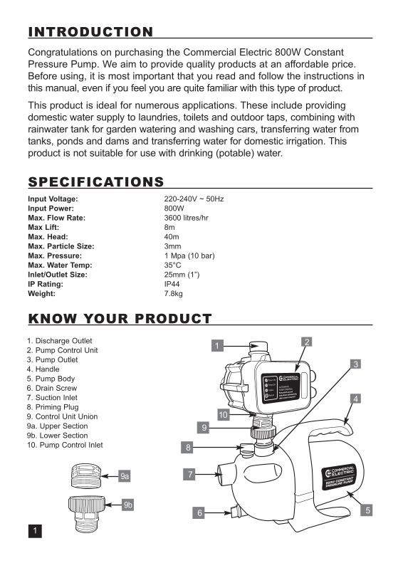
1. Discharge Outlet2. Pump Control Unit3. Pump Outlet4. Handle5. Pump Body6. Drain Screw7. Suction Inlet8. Priming Plug9. Control Unit Union9a. Upper Section9b. Lower Section10. Pump Control Inlet
2
3
4
1
6
910
9a
9b
8
INTRODUCTION
Congratulations on purchasing the Commercial Electric 800W ConstantPressure Pump. We aim to provide quality products at an affordable price.Before using, it is most important that you read and follow the instructions inthis manual, even if you feel you are quite familiar with this type of product.
This product is ideal for numerous applications. These include providingdomestic water supply to laundries, toilets and outdoor taps, combining withrainwater tank for garden watering and washing cars, transferring water fromtanks, ponds and dams and transferring water for domestic irrigation. Thisproduct is not suitable for use with drinking (potable) water.
SPECIFICATIONSInput Voltage: 220-240V ~ 50HzInput Power: 800WMax. Flow Rate: 3600 litres/hrMax Lift: 8mMax. Head: 40mMax. Particle Size: 3mmMax. Pressure: 1 Mpa (10 bar)Max. Water Temp: 35°CInlet/Outlet Size: 25mm (1”)IP Rating: IP44Weight: 7.8kg
KNOW YOUR PRODUCT
1
2
TABLE OF CONTENTS
INTRODUCTION………………………………………………….……………….
SPECIFICATIONS …………………………….………………………………….
KNOW YOUR PRODUCT ……………………………………………………….
ELECTRICAL SAFETY……………………………………………….………….
GENERAL SAFETY INSTRUCTIONS………………………………………….
ADDITIONAL SAFETY INSTRUCTIONS FOR PUMPS………………………..
SUGGESTED APPLICATIONS………………………………………………….
PACK CONTENTS.......................................................................................
FITTINGS AND TOOLS REQUIRED FOR INSTALLATION........................
SET-UP & INSTALLATION……………………………………………….….…..
OPERATION…………………………………………………..…………………...
HINTS WHEN USING THE PUMP................................................................
MAINTENANCE ………………………………………..…………………………
SPARE PARTS..............................................................................................
TROUBLESHOOTING……………………………………………………………
DESCRIPTION OF SYMBOLS…………………………………………………..
WARRANTY……………………………………………………………………….
1
1
1
3
3
5
6
6
6
7
12
13
13
13
14
15
16

ELECTRICAL SAFETYWARNING! This product is not suitable for use with drinking (potable) water.
WARNING! When using mains-powered equipment, basic safety precautions, including thefollowing, should always be followed to reduce the risk of fire, electrical shock, personalinjury and material damage.
Read the whole manual carefully and make sure you understand the operating instructions prior to use.Save these instructions for future reference.The electric motor has been designed for 230V and 240V only. Always check that the power supplycorresponds to the voltage on the rating plate.
Note: The supply of 230V and 240V on Commercial Electric tools are interchangeable for Australiaand New Zealand.
This tool is earthed in accordance with AS/NZS 60335-2-41
Note: The Power Outlet used for the water pump is recommended to be protected by a 30mAresidual current device or earth leakage circuit breaker.
If the power outlet is external, ensure that it is weather proof. If the supply cord is damaged, it mustbe replaced by an electrician or a power tool repairer to avoid a hazard.
The water pump has a built-in thermal protection overload switch. The water pump stops if anoverload occurs. The motor restarts automatically after it has cooled down.
Using an extension leadAlways use an approved extension lead suitable for the power input of this product. Before use,inspect the extension lead for signs of damage, wear and ageing. Replace the extension lead ifdamaged or defective.
When using an extension lead on a reel, always unwind the lead completely. Use of an extensionlead not suitable for the power input of this product or which is damaged or defective may result in arisk of fire and electric shock.
GENERAL SAFETY INSTRUCTIONS
WARNING! Read all instructions. Failure to follow all instructions listed below may result inelectric shock, fire and/or serious injury. The term “Power Tool” in all of the warnings listed belowrefers to your mains operated (corded) power tool or battery operated (cordless) power tool.
SAVE THESE INSTRUCTIONS
1) WORK AREAa) Keep work area clean and well lit. Cluttered and dark areas invite accidents.b) Do not operate power tools in explosive atmospheres, such as in the presence of
flammable liquids, gases, or dust. Power tools create sparks which may ignite the dust or fumes.c) Keep children and bystanders away while operating a power tool. Distractions can cause you
to lose control.
!!
!!
!!
3

4
GENERAL SAFETY INSTRUCTIONS (cont.)2) ELECTRICAL SAFETYa) Power tool plugs must match the outlet. Never modify the plug in any way. Do not use any
adapter plugs with earthed (grounded) power tools. Unmodified plugs and matching outlets willreduce risk of electric shock.
b) Avoid body contact with earthed or grounded surfaces such as pipes, radiators, rangesand refrigerators. There is an increased risk of electric shock if your body is earthed or grounded.
c) Do not expose power tools to rain or wet conditions. Water entering a power tool will increasethe risk of electric shock.
d) Do not abuse the cord. Never use the cord for carrying, pulling or unplugging the powertool. Keep cord away from heat, oil, sharp edges or moving parts. Damaged or entangled cordsincrease the risk of electric shock.
e) Replacement of the supply cord. If the supply cord is damaged, it must be replaced by anelectrician or a power tool repairer.
f) When operating a power tool outdoors, use an extension cord suitable for outdoor use.Use of a cord suitable for outdoor use reduces the risk of electric shock.
g) Have your tool repaired by an electrician or a power tool repairer. This power tool complieswith relevant safety requirements. To avoid danger, electrical appliances must only be repaired byqualified personnel using original spare parts; otherwise this may result in considerable danger tothe user.
3) PERSONAL SAFETYa) Stay alert, watch what you are doing and use common sense when operating a power tool.
Do not use a power tool while you are tired or under the influence of drugs, alcohol or medication.A moment of inattention while operating power tools may result in serious personal injury.
b) Use safety equipment. Always wear eye protection. Safety equipment such as dust mask,nonskid safety shoes, hard hat, or hearing protection used for appropriate conditions will reducepersonal injuries.
c) Avoid accidental starting. Ensure the switch is in the off position before plugging in. Carryingpower tools with your finger on the switch or plugging in power tools that have the switch oninvites accidents.
d) Remove any adjusting key or wrench before turning the power tool on. A wrench or a keyleft attached to a rotating part of the power tool may result in personal injury.
e) Do not overreach. Keep proper footing and balance at all times. This enables better control ofthe power tool in unexpected situations.
f) Dress properly. Do not wear loose clothing or jewellery. Keep your hair, clothing and glovesaway from moving parts. Loose clothes, jewellery or long hair can be caught in moving parts.
g) If devices are provided for the connection of dust extraction and collection facilities, ensurethese are connected and properly used. Use of these devices can reduce dust related hazards.
4) POWER TOOL USE AND CAREa) Do not force the power tool. Use the correct power tool for your application. The correct power
tool will do the job better and safer at the rate for which it was designed.b) Do not use the power tool if the switch does not turn it on and off. Any power tool that
cannot be controlled with the switch is dangerous and must be repaired.c) Disconnect the plug from the power source before making any adjustments, changing
accessories, or storing power tools. Such preventive safety measures reduce the risk ofstarting the power tool accidentally.
d) Store idle power tools, unplugged & out of the reach of children and do not allow personsunfamiliar with the power tool or these instructions to operate the power tool. Power tools are dangerous in the hands of untrained users.
GENERAL SAFETY INSTRUCTIONS (cont.)e) Maintain power tools. Check for misalignment or binding of moving parts, breakage of parts and
any other condition that may affect the power tools operation. If damaged, have the power toolrepaired before use. Many accidents are caused by poorly maintained power tools.
f) Keep cutting tools sharp and clean. Properly maintained cutting tools with sharp cutting edgesare less likely to bind and are easier to control.
g) Use the power tool, accessories and tool bits etc., in accordance with these instructionsand in the manner intended for the particular type of power tool, taking into account theworking conditions and the work to be performed. Use of the power tool for operationsdifferent from intended could result in a hazardous situation.
5) SERVICEa) Have your power tool serviced by a qualified repair person using only identical
replacement parts. This will ensure that the safety of the power tool is maintained.
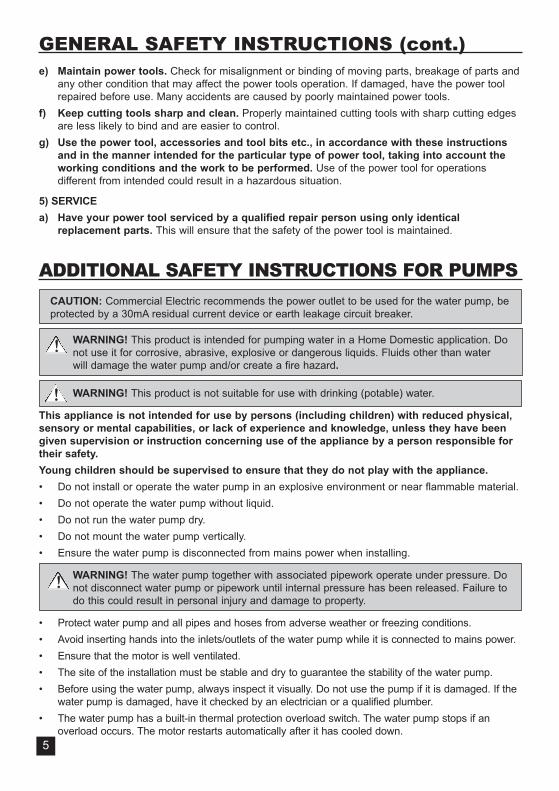
ADDITIONAL SAFETY INSTRUCTIONS FOR PUMPS
CAUTION: Commercial Electric recommends the power outlet to be used for the water pump, beprotected by a 30mA residual current device or earth leakage circuit breaker.
WARNING! This product is intended for pumping water in a Home Domestic application. Donot use it for corrosive, abrasive, explosive or dangerous liquids. Fluids other than waterwill damage the water pump and/or create a fire hazard.
WARNING! This product is not suitable for use with drinking (potable) water.
This appliance is not intended for use by persons (including children) with reduced physical,sensory or mental capabilities, or lack of experience and knowledge, unless they have beengiven supervision or instruction concerning use of the appliance by a person responsible fortheir safety.Young children should be supervised to ensure that they do not play with the appliance.• Do not install or operate the water pump in an explosive environment or near flammable material.• Do not operate the water pump without liquid.• Do not run the water pump dry.• Do not mount the water pump vertically.• Ensure the water pump is disconnected from mains power when installing.
WARNING! The water pump together with associated pipework operate under pressure. Donot disconnect water pump or pipework until internal pressure has been released. Failure todo this could result in personal injury and damage to property.
• Protect water pump and all pipes and hoses from adverse weather or freezing conditions.• Avoid inserting hands into the inlets/outlets of the water pump while it is connected to mains power.• Ensure that the motor is well ventilated.• The site of the installation must be stable and dry to guarantee the stability of the water pump.• Before using the water pump, always inspect it visually. Do not use the pump if it is damaged. If the
water pump is damaged, have it checked by an electrician or a qualified plumber.• The water pump has a built-in thermal protection overload switch. The water pump stops if an
overload occurs. The motor restarts automatically after it has cooled down.
!!
!!
5
!!
6
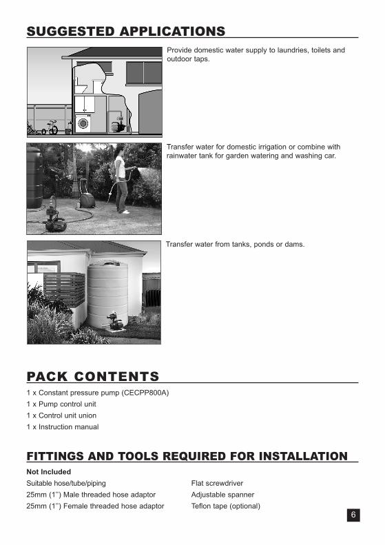
SUGGESTED APPLICATIONSProvide domestic water supply to laundries, toilets andoutdoor taps.
Transfer water for domestic irrigation or combine withrainwater tank for garden watering and washing car.
Transfer water from tanks, ponds or dams.
PACK CONTENTS1 x Constant pressure pump (CECPP800A)1 x Pump control unit1 x Control unit union1 x Instruction manual
FITTINGS AND TOOLS REQUIRED FOR INSTALLATIONNot IncludedSuitable hose/tube/piping Flat screwdriver25mm (1’’) Male threaded hose adaptor Adjustable spanner25mm (1’’) Female threaded hose adaptor Teflon tape (optional)

!!
!!
SET-UP & INSTALLATIONWARNING! This product is intended for pumping water in a home domestic application. Donot use it for corrosive, abrasive, explosive or dangerous liquids. Fluids other than waterwill damage the water pump and/or create a fire hazard.
WARNING! Disconnect the plug from the mains power prior to making any adjustments orinstallation.
• After removing the pump from its carton, check that the pump has not been damaged.• Unpack the contents.NOTE: Use the handle (4) when lifting or moving the pump (Fig. 1).NOTE: Position the pump on a solid and level surface. Do not store or use thepump in a vertical position. To ensure the most efficient operation, carefulplanning is advised when installing the pump.
CAUTION! It is recommended to have a 30mA residual current device connected when using the pump.
Assembling the Double Knuckle Assembly and Pump Control UnitNOTE: Teflon tape (not included) is recommended on threads to ensure a water tight seal andprevent any leakage.
1. Insert the control unit union (9) into the pump outlet (3) (Fig.2). Handtighten the control unit union (9) clockwise onto the pump body (5).Then use an adjustable spanner (not included) to ensure a firm fit.
2. Unscrew the upper section (9a) of the control unit union (9) from thelocking nut. Taking care that the lower section (9b) of the control unitunion still remains attached to the pump outlet (3) (Fig. 3).
3. Screw the removed upper section (9a) of the control unit union ontothe pump control inlet (10) (Fig.4). Then use an adjustable spanner (not included) to ensure a firm fit. Fig. 4
Fig. 1
7
Fig. 2
Locking nut
Fig. 3
8
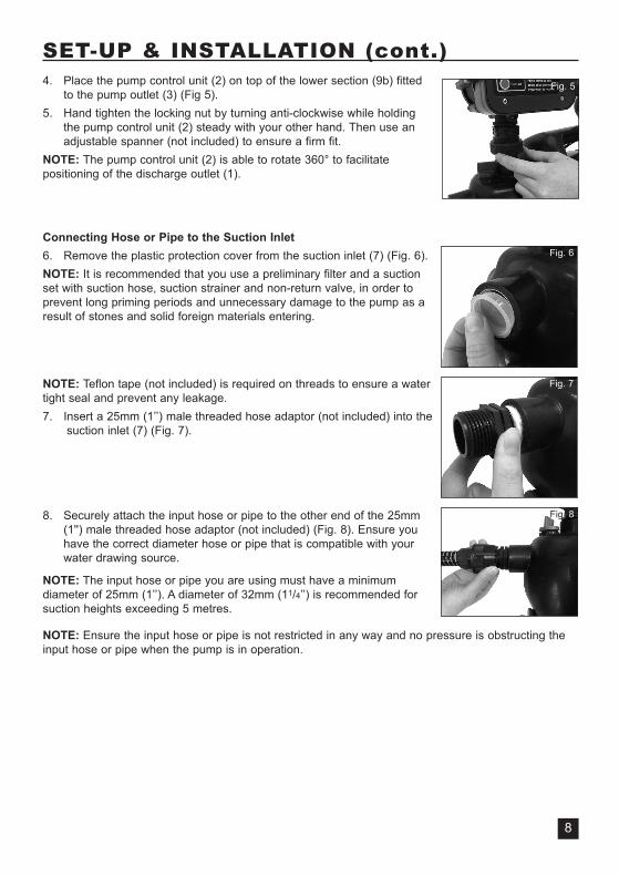
SET-UP & INSTALLATION (cont.)4. Place the pump control unit (2) on top of the lower section (9b) fitted
to the pump outlet (3) (Fig 5). 5. Hand tighten the locking nut by turning anti-clockwise while holding
the pump control unit (2) steady with your other hand. Then use anadjustable spanner (not included) to ensure a firm fit.
NOTE: The pump control unit (2) is able to rotate 360° to facilitatepositioning of the discharge outlet (1).
Connecting Hose or Pipe to the Suction Inlet6. Remove the plastic protection cover from the suction inlet (7) (Fig. 6).NOTE: It is recommended that you use a preliminary filter and a suctionset with suction hose, suction strainer and non-return valve, in order toprevent long priming periods and unnecessary damage to the pump as aresult of stones and solid foreign materials entering.
NOTE: Teflon tape (not included) is required on threads to ensure a watertight seal and prevent any leakage.7. Insert a 25mm (1’’) male threaded hose adaptor (not included) into the
suction inlet (7) (Fig. 7).
8. Securely attach the input hose or pipe to the other end of the 25mm(1'') male threaded hose adaptor (not included) (Fig. 8). Ensure youhave the correct diameter hose or pipe that is compatible with yourwater drawing source.
NOTE: The input hose or pipe you are using must have a minimumdiameter of 25mm (1’’). A diameter of 32mm (11/4’’) is recommended forsuction heights exceeding 5 metres.
NOTE: Ensure the input hose or pipe is not restricted in any way and no pressure is obstructing theinput hose or pipe when the pump is in operation.
Fig. 5
Fig. 6
Fig. 7
Fig. 8
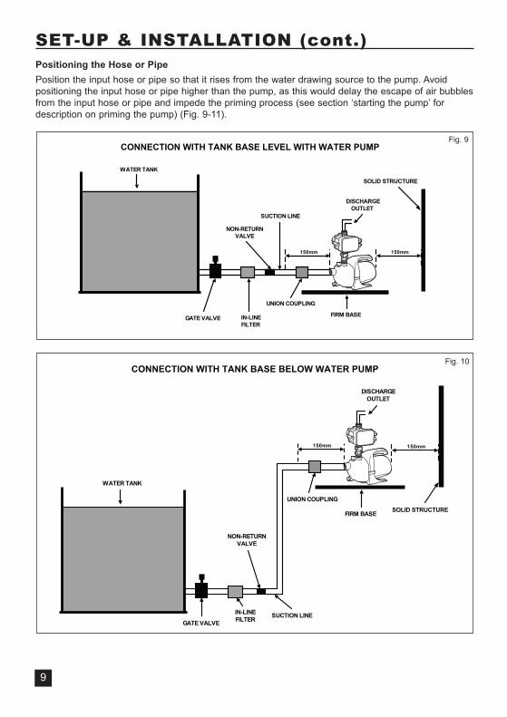
SET-UP & INSTALLATION (cont.)Positioning the Hose or PipePosition the input hose or pipe so that it rises from the water drawing source to the pump. Avoidpositioning the input hose or pipe higher than the pump, as this would delay the escape of air bubblesfrom the input hose or pipe and impede the priming process (see section ‘starting the pump’ fordescription on priming the pump) (Fig. 9-11).
mm051mm051
WATER TANK
GATE VALVE IN-LINEFILTER
NON-RETURNVALVE
UNION COUPLING
SUCTION LINE
FIRM BASE
DISCHARGEOUTLET
CONNECTION WITH TANK BASE LEVEL WITH WATER PUMP
SOLID STRUCTURE
Fig. 9
9
150mm
WATER TANK
GATE VALVE
IN-LINEFILTER
NON-RETURNVALVE
UNION COUPLING
SUCTION LINE
FIRM BASE
DISCHARGEOUTLET
CONNECTION WITH TANK BASE BELOW WATER PUMP
150mm
SOLID STRUCTURE
Fig. 10
10
!!
SET-UP & INSTALLATION (cont.)
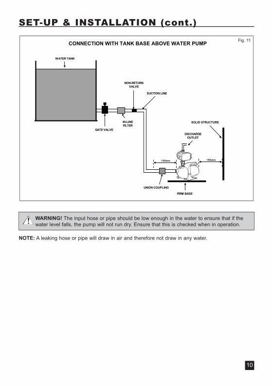
WARNING! The input hose or pipe should be low enough in the water to ensure that if thewater level falls, the pump will not run dry. Ensure that this is checked when in operation.
NOTE: A leaking hose or pipe will draw in air and therefore not draw in any water.
WATER TANK
NON-RETURNVALVE
SUCTION LINE
UNION COUPLING
CONNECTION WITH TANK BASE ABOVE WATER PUMP
150mm
FIRM BASE
DISCHARGEOUTLET
IN-LINEFILTER
GATE VALVE
150mm
SOLID STRUCTURE
Fig. 11
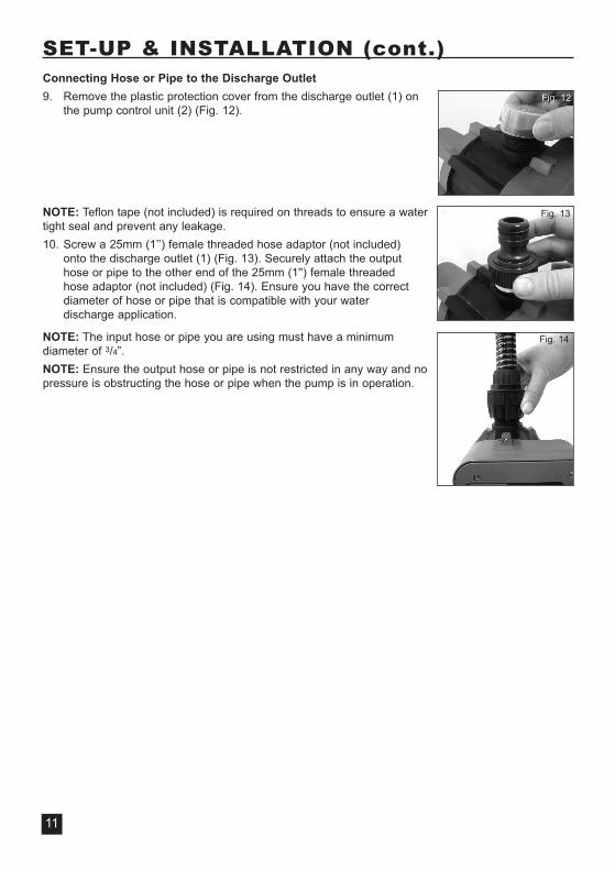
SET-UP & INSTALLATION (cont.)Connecting Hose or Pipe to the Discharge Outlet9. Remove the plastic protection cover from the discharge outlet (1) on
the pump control unit (2) (Fig. 12).
NOTE: Teflon tape (not included) is required on threads to ensure a watertight seal and prevent any leakage.10. Screw a 25mm (1’’) female threaded hose adaptor (not included)
onto the discharge outlet (1) (Fig. 13). Securely attach the outputhose or pipe to the other end of the 25mm (1'') female threaded hose adaptor (not included) (Fig. 14). Ensure you have the correctdiameter of hose or pipe that is compatible with your water discharge application.
NOTE: The input hose or pipe you are using must have a minimumdiameter of 3/4”. NOTE: Ensure the output hose or pipe is not restricted in any way and nopressure is obstructing the hose or pipe when the pump is in operation.
11
Fig. 13
Fig. 14
Fig. 12
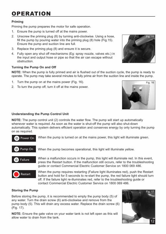
OPERATIONPrimingPriming the pump prepares the motor for safe operation.1. Ensure the pump is turned off at the mains power.2. Unscrew the priming plug (8) by turning anti-clockwise. Using a hose,
fill the pump by pouring water into the priming plug (8) hole (Fig.15).Ensure the pump and suction line are full.
3. Replace the priming plug (8) and ensure it is secure.4. Fully open any shut off mechanisms (Eg: spray nozzle, valves etc.) in
the input and output hose or pipe so that the air can escape withoutobstruction.
Turning the Pump On and OffNOTE: When the pump is fully primed and air is flushed out of the suction cycle, the pump is ready tooperate. The pump may take several minutes to fully prime air from the suction line and inside the pump.
1. Turn the pump on at the mains power (Fig. 16).2. To turn the pump off, turn it off at the mains power.
Understanding the Pump Control Unit
NOTE: The pump control unit (2) controls the water flow. The pump will start up automaticallywhenever water is required. As soon as the water is shut-off the pump will also shut-downautomatically. This system delivers efficient operation and conserves energy by only turning the pumpon as required.
When the pump is turned on at the mains power, this light will illuminate green.
When the pump becomes operational, this light will illuminate yellow.
When a malfunction occurs in the pump, this light will illuminate red. In this event,press the Restart button. If the malfunction still occurs, refer to the troubleshootingguide or contact Commercial Electric Customer Service on 1800 069 486.
When the pump requires restarting (Failure light illuminates red), push the Restartbutton and hold for 5 seconds to re-start the pump, the red failure light should turnoff. If the failure light re-illuminates red, refer to the troubleshooting guide orcontact Commercial Electric Customer Service on 1800 069 486.
Storing the Pump
Before storing the pump, it is recommended to empty the pump body (5) ofany water. Turn the drain screw (6) anti-clockwise and remove from thepump body (5). This will drain any excess water. Replace the drain screw (6)(Fig. 17).
NOTE: Ensure the gate valve on your water tank is not left open as this willallow water to drain from the tank.
Fig. 17
Fig. 15
Fig. 16
12
HINTS WHEN USING THE PUMP• The maximum pumping rate only occurs when using the largest hose or tube diameter possible, if
smaller hoses or tubes are used, the flow rate will reduce relative to the size of the tube or hose.Try to use discharge hoses or tubes which have a larger diameter than the discharge outlet (1).
• Position the pump as close as possible to your water source.
• Locate the pump at least 150mm from a solid structure (i.e: wall or fence).
• Running the pump with no water flowing through leads to increased wear and is notrecommended. The pump must be immediately unplugged as soon as water stops flowingthrough it.
The pump is automatically switched off in the event of overheating due to the built in thermaloverload protector. After cooling down, the motor automatically switches on again.
• When disconnecting the pump from the mains power supply, do not pull by the power cable.Using three fingers around the three pin power plug, gently disconnect from the mains power.
MAINTENANCEIn ordinary conditions, this pump does not require any maintenance.
Make sure the pump is disconnected from electric power supply before performing maintenance operation.
Cleaning the pump body
Use a moist cloth to wipe down the pump body (5). Allow to dry thoroughly before storing in a drylocation that is protected from bad weather conditions.
If the pump is not going to be used for a long period of time, it is advisable to rinse with water. Ensurethe pump is completely dry before storing.
SPARE PARTSLimited spare parts are available subject to availability. Please contact your local Bunnings SpecialOrders Desk to order the required spare parts.Most common spare parts listed belowSpare Part Part No.Drain screw SPCECPP0001Venturi tube SPCECPP0005Control unit union SPCECPP0057Pump control unit SPCECPP0058
13

14
TROUBLESHOOTING
Symptom Possible Cause Suggested Solution
The pump does notpump water/themotor does not run
There is no power reachingthe pump, the power light isnot illuminated green
Check the mains power outlet, ensurethat the electrical plug of the pump hasbeen correctly inserted
The motor thermal overloadprotection is activated
Determine the cause of the problem andpress the Restart button for 5 secondsor wait for the motor to cool down andthen restart the pump
The pump doesn’t build upenough pressure to operate
Check the suction line connections forair leaks and tighten or fix where found
Check the water source tank has waterin it
The inlet or outlet hoseis blocked
Determine the cause and unblockthe pump
The motor runs butthe pump is notpumping water
The pump is sucking air Verify the joints are sealed tightly
The pump is not primed Fill the pump with water or wait for it tofinish priming
The pump or discharge outletis blocked
Check the pump and discharge outletfor any foreign matter and remove it
The pump does notproduce adequatepressure
Incorrect assembly leads toair and water leakage in thesuction and discharge lines
Ensure the suction and dischargelines are the correct length and allassembly instructions are adhered to
The failure lightcontinues toilluminate red afterpressing the restartbutton
Air leak in the suction line Check the suction line connections forair leaks and tighten or fix where found
Electrical fault with the pump Contact Commercial ElectricCustomer Service
15
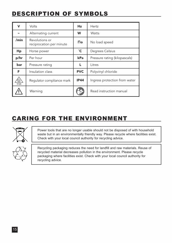
DESCRIPTION OF SYMBOLS
CARING FOR THE ENVIRONMENT
Power tools that are no longer usable should not be disposed of with householdwaste but in an environmentally friendly way. Please recycle where facilities exist.Check with your local council authority for recycling advice.
Recycling packaging reduces the need for landfill and raw materials. Reuse ofrecycled material decreases pollution in the environment. Please recyclepackaging where facilities exist. Check with your local council authority forrecycling advice.
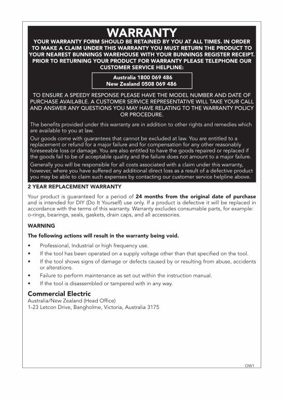
2 YEAR REPLACEMENT WARRANTY
Your product is guaranteed for a period of 24 months from the original date of purchase and is intended for DIY (Do It Yourself) use only. If a product is defective it will be replaced in accordance with the terms of this warranty. Warranty excludes consumable parts, for example: o-rings, bearings, seals, gaskets, drain caps, and all accessories.
WARNING
The following actions will result in the warranty being void.
Professional, Industrial or high frequency use.If the tool has been operated on a supply voltage other than that specified on the tool.If the tool shows signs of damage or defects caused by or resulting from abuse, accidents or alterations.Failure to perform maintenance as set out within the instruction manual.If the tool is disassembled or tampered with in any way.
Commercial ElectricAustralia/New Zealand (Head Office)1-23 Letcon Drive, Bangholme, Victoria, Australia 3175
•••
••
OW1
WARRANTYYOUR WARRANTY FORM SHOULD BE RETAINED BY YOU AT ALL TIMES. IN ORDER
TO MAKE A CLAIM UNDER THIS WARRANTY YOU MUST RETURN THE PRODUCT TO YOUR NEAREST BUNNINGS WAREHOUSE WITH YOUR BUNNINGS REGISTER RECEIPT.
PRIOR TO RETURNING YOUR PRODUCT FOR WARRANTY PLEASE TELEPHONE OUR CUSTOMER SERVICE HELPLINE:
TO ENSURE A SPEEDY RESPONSE PLEASE HAVE THE MODEL NUMBER AND DATE OF PURCHASE AVAILABLE. A CUSTOMER SERVICE REPRESENTATIVE WILL TAKE YOUR CALL AND ANSWER ANY QUESTIONS YOU MAY HAVE RELATING TO THE WARRANTY POLICY
OR PROCEDURE.
The benefits provided under this warranty are in addition to other rights and remedies which are available to you at law.Our goods come with guarantees that cannot be excluded at law. You are entitled to a replacement or refund for a major failure and for compensation for any other reasonably foreseeable loss or damage. You are also entitled to have the goods repaired or replaced if the goods fail to be of acceptable quality and the failure does not amount to a major failure. Generally you will be responsible for all costs associated with a claim under this warranty, however, where you have suffered any additional direct loss as a result of a defective product you may be able to claim such expenses by contacting our customer service helpline above.
`Australia 1800 069 486New Zealand 0508 069 486