zero-up 200w/400w/800w programmable dc power supplies ... · zero-up 200w/400w/800w programmable dc...
TRANSCRIPT

ZERO-UP 200W/400W/800WProgrammable DC Power Supplies Constant Voltage/Constant Current
Built-in RS-232 & RS-485 Interfacewith GPIB option.
ZERO-UP 200W/400W/800WProgrammable DC Power Supplies IA
549-
04-0
1 R
ev N
AD07
12
TDK-Lambda EMEAwww.emea.tdk-lambda.com
USER’S MANUAL
NORTH AMERICATDK-Lambda Americas Inc. 3055 Del Sol Boulevard San Diego, CA 92154 U.S.A.Tel: +1-619-575-4400 Fax: +1-619-575-7185www.us.tdk-lambda.com/lp
UK
TDK-Lambda UK Ltd.Kingsley Avenue Ilfracombe, DevonEX 34 8ES United KingdomTel: +44-1271-856666 Fax: +44-1271-864894E-mail: [email protected]
FRANCE
TDK-Lambda France SASZAC des Delaches BP 1077 - Gometz le Chatel 91940 LES ULIS Tel: +33 1 60 12 71 65 Fax: +33 1 60 12 71 66 E-mail: [email protected]
GERMANY
TDK-Lambda Germany GmbHKarl-Bold-Str.40,D-77855 Achern, GermanyTel: +49-7841-666-0 Fax: +49-7841-500-0E-mail: [email protected]
AUSTRIA
TDK-Lambda Austria Sales OfficeAredstrasse 22,A - 2544 Leobersdorf, AustriaTel: +43-2256-65584 Fax: +43-2256-64512E-mail: [email protected]
ITALY
TDK-Lambda Italy Sales OfficeVia dei Lavoratori 128/130IT20092 Cinisello Balsamo, Milano, ItalyTel: +39-02-6129-3863 Fax: +39-02-6129-0900E-mail: [email protected] www.it.tdk-lambda.com
ISRAEL
TDK-Lambda Ltd.Sales Office: Kibbutz Givat Hashlosha Tel-Aviv 4880000, IsraelTel: +972-3-9024-333 Fax: +972-3-9024-777Plant: 56 Haharoshet St. Karmiel Industrial Zone 2165158, IsraelTel: +972-4-9887-491 Fax: +972- 4-9583-071www.tdk-lambda.co.il E-mail: [email protected]
JAPAN
TDK-Lambda CorporationInternational Sales DivisonNittetsu Bldg. 6F, 1-13-1 Nihonbashi, Chuo-ku, Tokyo 103-0027, JapanTel: +81-3-5201-7175 Fax: +81-3-5201-7287www.tdk-lambda.com
CHINA
Shanghai Branch of Wuxi TDK-Lambda Electronic Co. Ltd.28F, Xingyuan Technology Building No.418, Guiping Road,Shanghai, China 200233Tel: +86-21-6485-0777 Fax: +86-21-6485-0666www. cn.tdk-lambda.comBeijing Branch of Wuxi TDK-Lambda Electronic Co. Ltd.Room 12B11-12B12, Unit 7 DACHENG SQUARE, No.28 Xuanwumenxi Street, Xuanwu District Beijing, 100053, CHINA Tel: +86-10-6310-4872 Fax: +86-10-6310-4874www. cn.tdk-lambda.comShenzhen Branch of Wuxi TDK-Lambda Electronics Co.Ltd.Room 4302, Excellence Times Square Building,4068 Yi Tian Road, Futian District,Shenzhen, China 518048Tel: +86 -755-83588261 Fax: +86 -755-83588260www. cn.tdk-lambda.com
KOREA
TDK-Lambda Corporation Seoul Office8F Songnam Bldg, 1358-6, Seocho-Dong,Seocho-Gu, Seoul, 137-862 KOREATel: +82-2-3473-7051 Fax: +82-2-3472-9137www.tdk-lambda.co.krwww.tdk-lambda.co.krSINGAPORE
TDK-Lambda Singapore Pte.Ltd.Blk 1008 Toa Payoh North # 07-01/03Singapore 318996Tel: +65-6251-7211 Fax: +65-6250-9171www.tdk-lambda.com.sg
INDIA
TDK-Lambda Bangalore Office#526, Ground Floor, 10th Main, 7th Cross,Jeevanbhimanagar , Bangalore 560 075Karnataka, India Tel: +91-80-43550 550 Fax: +91-80-43550 501www.tdk-lambda.com.sg
MALAYSIA
TDK-Lambda Malaysia Sdn. Bhd.c/o TDK (Malaysia) Sdn BhdLot 709, Nilai Industrial Estate 71800 NilaiNegeri Sembilan, MalaysiaTel: + 60 6-799 1130 Fax: + 60 6 799 3277www.tdk-lambda.com.my

IA-549-04-01N
DECLARATION OF CONFORMITYZUP SERIES
We, TDK-Lambda Ltd., of Industrial Zone P.O.B. 500 Karmiel, Israel, declare under our sole responsibil-ity that the ZUP200, ZUP400 and ZUP800 series as detailed on the attached products covered sheet, comply with the provisions of the following European Directive and are eligible to bear the CE mark:
Low Voltage Directive 2006/95/EC
Assurance of conformance of the described product with the provisions of the stated EC Directive is given through compliance to the following standard:
Electrical Safety EN 61010-1 :2001Electromagnetic Compatibility (EMC): EN 61326-1 :2006which cover testing to the following standards:EN 55011: 1998+A1: 1999+A2:2002 Conducted Emission: Class B
Radiated Emission Class AEN 61000-3-2: 2006 Class AEN 61000-3-3: 1995/A2:2005 Voltage FluctuationsEN 61000-4-2: 1995/A1 :1998/A2:2001 ESD AD: 4KV, CD:4KV Level 2EN 61000-4-3:2006 Radiated Immunity 3V/m Level 2EN 61000-4-4:2004 EFT/B Power leads: 1.0KV Level 2
Signal leads: 0.5KVEN 61000-4-5:2006 Conductive Surges Common mode: 2KV Level 3
Differential mode: 1 KV
EN 61000-4-6:1996/A1:2001 Conducted Disturbances 3Vrms Level 2EN 61000-4-11:2004 Voltage Dips
Our European Representative in the EU is TDK-Lambda UK Limited, located at Kingsley Avenue, IIfracombe,Devon, EX34 8ES UK.
Name of Authorized Signatory Martin Southam
Signature of Authorized Signatory
Position of Authorized Signatory European Marketing Director
Date 25th July 2012
Date Series first CE marked 26 April 1999
Place where signed Ilfracombe, Devon, England
PRODUCTS COVERED SHEET FOR:ZUP200 series: ZUP6-33, ZUP10-20, ZUP20-10, ZUP36-6, ZUP60-3.5, ZUP80-2.5, ZUP120-1.8ZUP400 series: ZUP6-66; ZUP10-40, ZUP20-20, ZUP36-12, ZUP60-7, ZUP80-5, ZUP120-3.6ZUP800 series: ZUP6-132, ZUP10-80, ZUP20-40, ZUP36-24, ZUP60-14
TDK-Lambda Ltd., Induslrial Zone P.O.B. 500 Karmiel, Israel

This
info
rmat
ion
shee
t was
pre
pare
d ba
sed
on P
eopl
e's R
epub
lic o
f Chi
na "
Man
agem
ent M
etho
ds fo
r Con
trolli
ng P
ollu
tion
Cau
sed
by E
lect
roni
c In
form
atio
n Pr
oduc
ts R
egul
atio
n"an
d"S
J/T
1136
4—20
06 M
arki
ng fo
r Con
trol o
f Pol
lutio
n C
ause
d by
Ele
ctro
nic
Info
rmat
ion
Prod
ucts".
As P
eopl
e's R
epub
lic o
f Chi
na "
Man
agem
ent M
etho
ds fo
r Con
trolli
ng P
ollu
tion
Cau
sed
by E
lect
roni
c In
form
atio
n Pr
oduc
ts R
egul
atio
n"is
a d
iffer
ent l
egis
latio
n fr
om E
U R
oHS
Dire
ctiv
e (
2002
/95/
EC)
, inq
uirie
s con
cern
ing
EU
RoH
S D
irect
ive (
2002
/95/
EC)
info
rmat
ion
shou
ld b
e do
ne se
para
tely.
The
dat
e of
man
ufac
ture
Part
Nam
eZ
UP2
00W
/400
W/8
00W
PO
WE
R S
UPP
LY
SE
RIE
SPr
oduc
t Wei
ght Z
UP2
002.
9Kg
Prod
uct W
eigh
t ZU
P400
3.2K
g
Prod
uct W
eigh
t ZU
P800
5.8K
g
Lead
(Pb)
Mer
cury
(Hg)
Cad
miu
m (C
d)H
exav
alen
t C
hrom
ium
(Cr6
+)Po
lybr
omin
ated
Bip
heny
ls(
PBB)
Poly
brom
inat
ed D
iphe
nyl
Ethe
rs(
PBD
E)
0.1w
t%0.1w
t%0.01wt%
0.1w
t%0.1w
t%0.1w
t%
Cas
eO
OO
OO
OPl
astic
pan
elO
OO
OO
OPC
B's
asse
mbl
yX
OO
OO
OIn
ner m
etal
par
tsO
OO
OO
OIn
ner c
able
sO
OO
OO
OA
cces
sorie
sO
OO
OO
OPr
ovid
ed in
the
pack
age
○ : I
ndic
ates
that
the
conc
entra
tion
valu
es o
f tox
ic a
nd h
azar
dous
subs
tanc
es in
all
"hom
ogen
eous
mat
eria
ls"
of re
spec
tive
parts
and
mat
eria
ls d
oes n
ot e
xcee
d th
e co
ncen
tratio
n lim
its
regu
late
d by
"SJ
/T 1
1363
-200
6 R
equi
rem
ents
for C
once
ntra
tion
Lim
its fo
r Cer
tain
Haz
ardo
us S
ubst
ance
s in
Elec
troni
c In
form
atio
n Pr
oduc
ts".
× : I
ndic
ates
that
the
conc
entra
tion
valu
e of
a to
xic
or h
azar
dous
subs
tanc
e in
clud
ed in
a "
hom
ogen
eous
par
t" o
f a re
spec
tive
part
ot m
ater
ial e
xcee
ds th
e co
ncen
tratio
n lim
it re
gula
ted
by
"S
J/T
1136
3-20
06 R
equi
rem
ents
for C
once
ntra
tion
Lim
its fo
r Cer
tain
Haz
ardo
us S
ubst
ance
s in
Elec
troni
c In
form
atio
n Pr
oduc
ts".
Info
rmat
ion
Con
cern
ing
Incl
usio
n of
Tox
ic a
nd H
azar
dous
Sub
stan
ces
Not
esC
once
ntra
tion
Val
ues o
f Tox
ic a
nd H
azar
dous
Sub
stan
ces/
Elem
ents
(wt%
)
Subp
art N
ame

TABLE OF CONTENTS: ZUP SERIES
SAFETY INSTRUCTIONS .....................................................................
WARRANTY ..........................................................................................
CHAPTER 1. General Information
CHAPTER 2. Specifications
CHAPTER 3. Installation
......................................................1.1 User manual content1.2 Introduction
1.2.1 General description1.2.2 Configurations1.2.3 Control via the serial communication port1.2.4 Output connections1.2.5 Analog voltage programming1.2.6 Parallel operation1.2.7 Cooling and mechanical construction .....................................
1.3 Accessories1.3.1 General1.3.2 Serial link cables1.3.3 AC cables1.3.4 Front panel outputs option
................................................................2.1 200W/400W Series
800W Series...................................................................................2.2 Supplemental characteristics .........................................................
.....................................................................3.1 General3.2 Initial inspection
3.2.1 Mechanical inspection3.2.2 Preparation for use
3.3 AC source requirements3.4 Cooling and placement3.5 Rack mounting3.6 Power connection3.7 Connecting the load .......................................................................
3.7.1 Selecting wire size3.7.2 Wire termination .....................................................................3.7.3 Single load connection, local sense3.7.4 Single load connection, remote sensing ................................3.7.5 Multiple load connections, radial distribution method3.7.6 Multiple load connections with distribution terminals .............3.7.7 Grounding outputs
3.8 External control connector3.8.1 General3.8.2 Pin description .......................................................................3.8.3 Technical description3.8.4 Default connections................................................................
3.9 Repackaging for shipment
pg. 2
pg. 1
pg. 5
pg. 6
pg. 7
pg. 9
pg. 11
pg. 12
pg.13
pg.14
pg.15
pg.16
pg.17
pg.18

Table 4-1: Front panel controls and indicators .......................................4.2.2 Rear panel ............................................................................4.2.3 Rear panel connections description .....................................
4.3 Turn-on Checkout Procedure4.3.1 General4.3.2 Prior to operation4.3.3 Constant Voltage check4.3.4 Constant Current check ........................................................4.3.5 OVP check4.3.6 UVP check4.3.7 Foldback check4.3.8 Output On/Off4.3.9 Address setting4.3.10 Local/Remote Operation
4.4 Local Operation ...............................................................................4.4.1 Introduction4.4.2 Constant Voltage Operation4.4.3 Constant Current Operation4.4.4 Automatic Crossover ..............................................................4.4.5 Over Voltage protection (OVP)4.4.6 Under Voltage Protection (UVP)4.4.7 Foldback Protection ................................................................4.4.8 Output On/Off Control4.4.9 Last Setting memory ...............................................................4.4.10 Output Voltage & Current programming by external resistor4.4.11 Output Voltage Programming by external voltage .................4.4.12 Output Current programming by external voltage4.4.13 Auto Parallel operation...........................................................4.4.14 Series Operation ....................................................................4.4.15 Output good signal.................................................................
.....................................5.1 Introduction5.2 Configuration
5.2.1 Address setting5.2.2 RS232 or RS485 selection5.2.3 Baud rate setting5.2.4 Local/remote selection
CHAPTER 5. RS232 & RS485 remote control
.................................................4.1 Introduction4.2 Controls and Indicators
4.2.1 Front Panel
CHAPTER 4. Operating Instructions.
pg.23
pg.22
pg.24pg.25
pg.26
pg.27
pg.28
pg.29
pg.30
pg.32
pg.33
pg.37
pg.38
pg.35
TABLE OF CONTENTS: ZUP SERIES
3.10 Outline drawings: ZUP 200W & 400W series.................................3.11 Outline drawing: ZUP 800W series...............................................3.12 Outline drawing: front panel connector option ...............................
pg.19pg.20
pg.21

5.4.1 Introduction5.4.2 RS485 cable5.4.3 Linking power supplies
5.5 ZUP series command set description5.5.1 ID control commands...............................................................5.5.2 Initialization control5.5.3 Output control..........................................................................5.5.4 Status control ..........................................................................5.5.4.1 Registers structure5.5.4.2 Status control commands ....................................................
5.6 Communication Protocol..................................................................5.6.1 General information5.6.2 Accessing a ZUP unit5.6.3 End of message5.6.4 Communication Test set up.................................................... pg.48
5.7.Service Request................................................................................. pg.49
................................................................... pg.506.1 Introduction6.2 Units under warranty6.3 Periodic Maintenance6.4 Adjustment and calibration6.5 Part replacement and repairs6.6 Fuse ratings
...................................................................... pg.51
CHAPTER 6. Maintenance
USER’S MANUAL INDEX
pg.45
pg.42
pg.46
pg.43
pg.47
5.7.1 Service Request (SRQ)5.7.2 Service Request message5.7.3 Service Request enable/disable commands
TABLE OF CONTENTS: ZUP SERIES
5.3 Remote programming via RS232.....................................................5.3.1 Introduction5.3.2 Rear panel connectors pinout5.3.3 RS232 cable ............................................................................5.3.4 Linking power supplies
5.4 Remote programming via RS485 .....................................................
pg.39
pg.40
pg.41

WARRANTY SERVICE
WARRANTY
DISCLAIMER
LIMITATION OF WARRANTY
TRADEMARK INFORMATION
This product must be returned to an authorized Nemic-Lambda service facility for repairs or otherwarranty service. For products returned to Nemic-Lambda for warranty service, the buyer shall prepayshipping charges to Nemic-Lambda and Nemic-Lambda shall pay the shipping charges to return theproduct to the buyer.
This Nemic-Lambda product is warranted against defects in materials and workmanship for a period ofthree years from date of shipment .During the warranty period, Nemic-Lambda will, at it’s option, eitherrepair or replace products which prove to be defective.
The information contained in this document is subject to change without notice. Nemic-Lambda shallnot be liable for errors contained in this document or for incidental or consequential damages inconnection with the furnishing, performance or use of this material. No part of this document may bephotocopied, reproduced or translated into another language without the prior written consent ofNemic-Lambda.
The warranty shall not apply to defects resulting from improper or inadequate usage or maintenance bythe buyer , buyer supplied products or interfacing. The warranty shall not apply to defects resultingfrom unauthorized modifications or from operation exceeding the environmental specifications of theproduct.Nemic-Lambda does not warrant the buyers circuitry or malfunctions of Nemic-Lambda productsresulting from the buyer’s circuitry. Furthermore, Nemic-Lambda does not warrant any damageoccurring as a result of the buyer’s circuitry or the buyer’s - supplied products.No other warranty is expressed or implied.
Microsoft and Windows are trademarks of Microsoft Corporation.

SAFETY INSTRUCTIONS
CAUTION
INSTALLATION CATEGORY
GROUNDING
FUSES
LIVE CIRCUITS
PART SUBSTITUTIONS & MODIFICATIONS
ENVIRONMENTAL CONDITIONS
INPUT RATINGS
The following safety precaution must be observed during all phases of operation, service and repair ofthis equipment. Failure to comply with the safety precautions or warnings in this document violatessafety standards of design, manufacture and intended use of this equipment and may impair the built-inprotections within.Nemic-Lambda shall not be liable for user’s failure to comply with these requirements.
The ZUP Series has been evaluated to INSTALLATION CATEGORY II. Installation Category (overvoltage category) II: local level, appliances, portable equipment etc.. With smaller transient overvoltages than Installation Category (over voltage category) III.
This product is a Safety Class 1 instrument. To minimize shock hazard, the instrument chassis must beconnected to an electrical ground. The instrument must be connected to the AC power supply mainsthrough a three conductor power cable, with the ground wire firmly connected to an electrical ground(safety ground) at the power outlet.For instruments designed to be hard - wired to the supply mains, the protective earth terminal must beconnected to the safety electrical ground before an other connection is made. Any interruption of theprotective ground conductor, or disconnection of the protective earth terminal will cause a potentialshock hazard that might cause personal injury.
Fuse must be changed by authorized Nemic-Lambda service personnel only. For continued protectionagainst risk of fire, replace only with the same type and rating of fuse. Refer to maintenance instructionsin chapter 6 for fuse rating.
Operating personnel must not remove the instrument cover. No internal adjustment or componentreplacement is allowed by non-Nemic-Lambda qualified service personnel. Never replacecomponents with power cable connected. To avoid injuries, always disconnect power, dischargecircuits and remove external voltage sources before touching components.
Part substitutions and modifications are allowed by authorized Nemic-Lambda service personnel only.For repairs or modifications, the instrument must be returned to a Nemic-Lambda service facility.
The ZUP series safety approval applies to the following operating conditions:* Indoor use * Ambient temperature: 0 C to 50 C* Maximum relative humidity: 90% (no dew drop) * Altitude: up to 3,000 m* Pollution degree 2
O O
Do not use AC supply which exceeds the input voltage and frequency rating of this instrument. Theinput voltage and frequency rating of the ZUP Series is; 100-240V~, 50/60Hz. For safety reasons, themains supply voltage fluctuations should not exceed +/- 10% of nominal voltage.

SAFETY INSTRUCTIONS
SAFETY SYMBOLS
Instruction manual symbol. The instrument will be marked with this symbol when it isnecessary for the user to refer to the instruction manual.
Indicates hazardous voltage.
Indicates ground terminal.
The WARNING sign denotes a hazard.An attention to a procedure is called.Not following procedure correctly could result in personal injury.AWARNING sign should not be skipped and all indicated conditions must befully understood and met.
The CAUTION sign denotes a hazard.An attention to a procedure is called.Not following procedure correctly could result in damage to the equipment.Do not proceed beyond a CAUTION sign until all indicated conditions arefully understood and met.
FCC COMPLIANCE NOTICE:Note: This equipment has been tested and found to comply with the limits for a Class A digitaldevice, pursuant to part 15 of the FCC Rules. These limits are designed to provide reasonableprotection against harmful interference when the equipment is operated in a commercialenvironment. This equipment generates uses, and can radiate radio frequency energy and, ifnot installed and used in accordance with the instruction manual, may cause harmfulinterference to radio communications. Operation of this equipment in a residential area islikely to cause harmful interference in which case the user will be required to correct theinterference at his own expense.
!
WARNING
CAUTION

OUTPUT TERMINALS COVERModels up to 60V output voltage
After connection of the load wires ( refer to par. 3-7 ), attach the plastic cover to the rear panel of thepower supply, using two self tapping screws supplied with the unit. Refer to Fig. 1-1 for details.
Fig. 1-2: Output wires connection
OUTPUT CONNECTOR COVER80V and 120V models
MALE CONNECTOR (PSC1.5/3-M-PE , Phoenix)
FEMALE PLUG (PSC 1.5/3-F)
PLASTIC PLUG COVER
Wires : Copper , AWG16-30
Tightening torque : 4lib-in
WARNING
Hazardous voltages may exist at the output terminals.Attach the terminals cover, supplied with the unit, to the chassis after connecting the load wires asdescribed below.
Fig. 1-1: Terminals cover assembly
REAR PANEL
LOAD WIRES
PLASTIC COVER
SAFETY INSTRUCTIONS
+V-V

CHAPTER 1 GENERAL INFORMATION
1.1 USER’S MANUAL CONTENT
1.2 INTRODUCTION
1.2.1 General description
1.2.2 Configurations
1.2.4 Output connections
1.2.5 Analog voltage programming
1.2.6 Parallel operation
1.2.3 Control via the serial communication port
This user’s manual contains the operating instructions, installation instructions and specifications ofthe ZUP series. For information related to operation with GPIB control, refer to Nemic-Lambda GP485user’s manual.
The ZUP series are wide range output switching power supplies with laboratory performance. The ZUPseries is power factor corrected and operates from worldwide AC voltage range continuously. Outputvoltage and current are continuously displayed and LED indicators show the complete operating statusof the power supply. The front panel controls allow the user to set the output parameters, the protectionlevels (over-voltage / under-voltage)and arm the foldback protection to disable the output if the unitswitches from Constant-voltage mode to Constant-current mode.
The ZUP can be configured into a programmable power system of up to 31 DC outputs using the built-inRS232 or RS485 communication port in the power supply. In a GPIB system the GP485 controller cancontrol up to 31 ZUP units in a single GPIB address.
Output connections are made to rear panel bus-bars for models up to 60V and connector for the 80Vand 120V models. Either the positive or negative terminal may be grounded or the output may befloated. The maximum potential (including the output voltage) that either output terminal is from groundmust not exceed the rated output voltage. Local or remote sense may be used. In remote sense, themaximum voltage drop on each wire is 0.5V for models up to 60V and 2V for the 80V and 120V models.
Analog inputs are provided at the rear panel for analog voltage programming of output voltage andcurrent, and On/Off control. Inputs are provided for resistive programming of the output voltage andcurrent.
Zup units of the same output voltage and current rating can be paralleled in master-slave configurationwith automatic current sharing for power-up purposes.
The following parameters can be programmed via the serial communication port:
1. Output voltage setting2. Output current setting3. Output On/Off4.Arming or release of the foldback protection5. Over-voltage protection setting6. ‘Soft’ under-voltage limit7. Output voltage measurement
8. Output current measurement9. Power supply start-up mode
(last setting or safe mode)10. Over-voltage protection setting read11. Under-voltage limit read12. Remote/Local Control

1.3.1 General
1.3.4 Front Panel Outputs option
1.3.3 AC Cables
1.3.2 Serial link cables
1.3 ACCESSORIES
Accessories are delivered with the power supply or separately upon ordering.Below are listed possible accessories and ordering numbers.
PART No. DESCRIPTION
NL100 19” rack, 3U heightNL200 Dual output packingNL101 Blank panel for 19” rackNL102 Additional instruction manual
PART No. MARKET DESCRIPTION
ZUP/U USA 13A, 125V, unshielded, 2m typ. length, with IEC320 connector on one(NC301) side and NEMA-5-15P connector the on other side.
ZUP/E Europe 10A, 250V, unshielded, 2m typ. length, with IEC320 connector on one(NC302) side and INT’L7 standard VII, dual earthing on the other side.
ZUP/O General 10A, 250V, unshielded, 2m typ. length, with IEC320 connector on one(NC303) side and unterminated stripped wires on the other side. Use the cable
only with plug approved by the national safety standards of the countryof usage.
ZUP/J Japan 13A, 125V unshielded, 2m typ. length, with IEC320 connector on one(NC305) side and Japan type plug on other side.
In cases where load connection at the front panel is required, optional Front Panel output Jacks for aload current of 20A maximum is available. Please note that the power supply height is increased withthis option. Refer to outline drawing (par. 3.12) for details.
ORDER No. DESCRIPTION
ZUP /L 20AFront Panel Output Jacks
Serial link cable, for linking power supplies by RS485 communication is provided with the power supplyaccording to order. Cable description: 0.5m typ. length, shielded, EIA-568Atype plugs, 8 contacts.Refer to par.5.3.4 , for details.
1.2.7 Cooling and mechanical constructionThe Zup series is fan cooled. Upon installation take care to allow free air flow into the power supply viathe front panel and out of the power supply via the rear panel. The ZUP series is contained in a compact,lightweight package which allows for easy installation and space saving in the application equipment.

CHAPTER 2 SPECIFICATIONS
2.1 SPECIFICATIONS: 200W/400W SeriesZ
UP
20
-2
0Z
UP
20
-1
0Z
UP
10
-4
0Z
UP
10
-2
0Z
UP
6-
66
ZU
P6
-3
3Z
UP
60
-7
0~
70
~1
2
ZU
P6
0-
3.5
0~
3.5
0~
6
21
64
32
21
04
20
ZU
P3
6-
12
ZU
P3
6-
6
0~
36
0~
60
ZU
P1
20
-3
.6Z
UP
12
0-
1.8
ZU
P8
0-
5Z
UP
80
-2
.5
V A W - -
mV
mV
mS - -
mS
mS
mS - -
mA - - - - - - V - - - - - - A - - % A
MO
DE
L
OU
TP
UT
VO
LTA
GE
(*1)
OU
TP
UT
CU
RR
EN
T(*
2)
RA
TE
DO
UT
PU
TP
OW
ER
LO
AD
RE
GU
LA
TIO
N
LIN
ER
EG
ULA
TIO
N
RM
SR
IPP
LE
RIP
PLE
RE
CO
VE
RY
TIM
E(*
4)
TE
MP
ER
AT
UR
EC
OE
FF
ICIE
NT
TE
MP
ER
AT
UR
ED
RIF
T
(5H
z-1
MH
zB
andw
idth
)
(pk
topk
20M
Hz
Bandw
idth
)
LO
AD
RE
GU
LA
TIO
N
LIN
ER
EG
ULA
TIO
N
RM
SR
IPP
LE
TE
MP
ER
AT
UR
EC
OE
FF
ICIE
NT
TE
MP
ER
AT
UR
ED
RIF
T
(5H
z-1
MH
zB
andw
idth
)
INP
UT
VO
LTA
GE
(*8)
INP
UT
CU
RR
EN
T(*
6)
INP
UT
CU
RR
EN
TH
AR
MO
NIC
S
PO
WE
RFA
CT
OR
(TY
P)
EF
FIC
IEN
CY
(*6)
INR
US
HC
UR
RE
NT
(*7)
100/2
00V
VO
LTA
GE
CU
RR
EN
T
STA
TU
S
UP
PR
OG
RA
MM
ING
RE
SP
ON
SE
TIM
E
FU
LL
LO
AD
NO
LO
AD
RE
SO
LU
TIO
N
AC
CU
RA
CY
RE
SO
LU
TIO
N
AC
CU
RA
CY
VO
LTA
GE
CU
RR
EN
T
CONSTANTVOLTAGE
CONSTANTCURRENT
DO
WN
PR
OG
RA
MM
ING
RE
SP
ON
SE
TIM
E
PROGRA-MING(*3)
DISPLAY
OV
ER
VO
LTA
GE
PR
OT
EC
TIO
N(*
5)
HO
LD
UP
TIM
E
OU
TP
UT
PR
OT
EC
TIO
NS
INPUT
10
5.6
/2
.75
.3/2
.6
80
/8
48
2/
86
15
5.6
/2
.74
.9/2
.4
80
/8
48
3/
87
0~
20
30
5.6
/2
.7
79
/8
3
0~
40
50
5.6
/2
.7
79
/8
2
0~
66
0.0
05
%+
2m
V(*
10
)0
.00
5%
+4
mV
0.0
05
%+
1m
V(*
11
)0
.00
5%
+2
mV
5 50
30
pp
m/
Cfr
om
rate
dvo
lta
ge
follo
win
g3
0-m
inu
tew
arm
-up
O
0.0
1%
+2
mV
ch
an
ge
ino
utp
ut
ove
r8
-ho
ur
inte
rva
lu
nd
er
co
nst a
nt
line
,lo
ad
an
da
mb
ien
tte
mp
era
ture
follo
win
g3
0-m
inu
tew
arm
-up
50
50
10
0
5.6
/2
.7
74
/7
7
15
15
15
15
15
15
15
55
55
5
2.9
/1
.42
.9/1
.4
75
/7
97
8/
82
7.5
2.9
/1
.42
.6/1
.3
76
/8
07
8/
82
0~
10
15
2.9
/1
.4
74
/7
8
0~
20
25
2.9
/1
.4
73
/7
7
0~
33
19
83
96
20
04
00
20
04
00
50
3.0
/1
.5
69
/7
2
15
/3
01
5/
30
15
/3
01
5/
30
15
/3
01
5/
30
15
/3
0
25
0
0-
7.5
1
35
0
0-1
3
0.5
40
0
0-
24
0.2
0.0
1%
+5
mA
for
loa
dvo
lta
ge
ch
an
ge
eq
ua
lto
un
itvo
lta
ge
ratin
g,
co
nsta
nt
inp
ut
vo
lta
ge
.
0.0
1%
+2
mA
fro
m8
5-1
32
VA
Co
r1
70
-26
5V
AC
,co
nsta
nt
loa
d
20
mS
at
10
0V
/20
0V
AC
,ra
ted
ou
tpu
tvo
lta
ge
an
do
utp
ut
cu
rre
nt
10
0p
pm
/C
fro
mra
ted
cu
rre
nt
follo
win
g3
0m
inu
tew
arm
-up
O
Be
tte
rth
an
0.0
28
%o
fra
ted
ou
tpu
tvo
lta
ge
0.0
2%
+5
mV
0.0
2%
+8
mV
0.0
2%
+1
2m
V0
.02
%+
26
mV
0.0
2%
+3
5m
V
0.4
%+
40
mA
Be
tte
rth
an
0.0
3%
of
rate
do
utp
ut
cu
rre
nt
0.0
2%
+5
mA
ch
an
ge
ino
utp
ut
ove
r8
-ho
ur
inte
rva
lu
nd
er
co
nst a
nt
line
,lo
ad
an
da
mb
ien
tte
mp
era
ture
follo
win
g3
0m
inu
tew
arm
-up
3d
igits
(6V
,2
0V
,3
6V
,6
0V
,8
0V
)3
.5d
igits
(10
V,
12
0V
)a
ccu
racy:
0.2
%+
/-2
dig
its
3d
igits
accu
racy:
0.5
%+
/-3
dig
its
CV
/CC
,A
larm
,F
old
,L
oca
l/R
em
ote
,O
N/O
FF
Ove
rV
olta
ge
,O
ve
rTe
mp
era
ture
,F
old
ba
ck
85
~2
65
VA
CC
on
tin
uo
us,
47
~6
3H
z
Co
mp
lies
with
EN
61
00
0-3
-2,
Cla
ss
A
0.9
9a
t1
00
/20
0V
AC
,1
00
%L
oa
d
50
0
0-
40
0.0
2%
+5
0m
V
0.4
%+
0.4
%+
0.4
%+
0.4
%+
15
mA
30
mA
10
mA
20
mA
0-
88
0-
13
2
0.0
2%
+8
0m
V
0.2
75
0
0-
66
0.2
10
0
0~
60
~1
00
~2
0
0~
1.8
0~
5
20
0~
3.6
0~
2.5
20
20
0
70
60
0.2
80
0
40
0
80
80
0.2
10
00
21
64
32
0~
80
0~
12
0

- - - - - - Kg
mm - - - - - - - - - - - - - - -
OP
ER
AT
ING
TE
MP
ER
AT
UR
E
OP
ER
AT
ING
HU
MID
ITY
ST
OR
AG
ET
EM
PE
RA
TU
RE
ST
OR
AG
EH
UM
IDIT
Y
VIB
RA
TIO
N(*
9)
SH
OC
K
WE
IGH
T
SIZ
E(W
xH
xD
)
OU
TP
UT
ON
/OF
F
OU
TP
UT
GO
OD
OU
TP
UT
VO
LTA
GE
PR
OG
R.
OU
TP
UT
CU
RR
EN
TP
RO
GR
.
RE
MO
TE
SE
NS
ING
CO
MM
UN
ICA
TIO
NIN
TE
RFA
CE
ENVIRON-MENT
MECHANI-CAL
EXTERNALFUNCTIONS
SA
FE
TY
STA
ND
AR
DS
EM
CS
TA
ND
AR
DS
APPRO-VALS
NO
TE
S:
*1
MIN
IMU
MV
OLTA
GE
ISG
UA
RA
NT
EE
DT
OM
AX
IMU
M0.2
%O
FT
HE
RA
TE
DO
UT
PU
TV
OLTA
GE
.
*2
MIN
IMU
MC
UR
RE
NT
ISG
UA
RA
NT
EE
DT
OM
AX
IMU
M0.4
%O
FT
HE
RA
TE
DO
UT
PU
TC
UR
RE
NT.
*3
GIV
EN
FO
RC
ON
TR
OL
OF
TH
EO
UT
PU
TV
IAT
HE
SE
RIA
LC
OM
MU
NIC
AT
ION
OR
VIA
FR
ON
TP
AN
EL
CO
NT
RO
LS
.
*4
TIM
EF
OR
RE
CO
VE
RY
TO
WIT
HIN
+/-
50m
VA
GA
INS
TC
UR
RE
NT
CH
AN
GE
OF
50%
TO
100%
.
*5
INV
ER
TE
RS
HU
TD
OW
NM
ET
HO
D,M
AN
UA
LR
ES
ET
BY
AC
INP
UT
RE
CY
CLIN
G.(
OV
PW
ILL
SH
UT
DO
WN
OU
TP
UT
).
*6
AT
100V
/200V
AN
DM
AX
IMU
MO
UT
PU
TP
OW
ER
.
*7
FO
R200W
UN
ITS
-A
TC
OLD
STA
RT
Ta
=25°C
.
*8
FO
RC
AS
ES
WH
ER
EC
ON
FO
RM
AN
CE
TO
VA
RIO
US
SA
FE
TY
SP
EC
S,(U
L,IE
CE
TC
.)A
RE
RE
QU
IRE
DT
OB
ED
ES
CR
IBE
D
AS
100-2
40V
AC
(50/6
0H
z)
ON
NA
ME
PLA
TE
.
*9
WH
EN
MO
UN
TE
DW
ITH
MO
UN
TIN
GS
CR
EW
S.
*10
FR
OM
NO
LO
AD
TO
FU
LL
LO
AD
,C
ON
STA
NT
INP
UT
VO
LTA
GE
AT
RE
MO
TE
SE
NS
E.
*11
FR
OM
85~
132V
AC
OR
170~
265V
AC
,C
ON
STA
NT
LO
AD
.
*12
FR
OM
ZE
RO
VO
LT
ST
OF
ULL
SC
ALE
,R
ES
IST
IVE
LO
AD
,C
UR
RE
NT
SE
TT
ING
AT
MA
X.
CO
ND
UC
TE
DE
MI
RA
DIA
TE
DE
MI
SE
RIA
LO
PE
RA
TIO
N
PA
RA
LLE
LO
PE
RA
TIO
N
CO
OLIN
G
ISO
LA
TIO
NR
ES
ISTA
NC
E
WIT
HS
TA
ND
VO
LTA
GE
ZU
P6
0-
7
3.2
3.2
3.2
ZU
P6
0-
3.5
2.9
2.9
2.9
ZU
P3
6-
12
ZU
P3
6-
6Z
UP
20
-2
0Z
UP
20
-1
0Z
UP
10
-4
0Z
UP
10
-2
0Z
UP
6-
66
0~
50
C:
10
0%
Lo
ad
.O
-20
~7
0C
O
30
~9
0%
RH
(N
oD
ew
dro
p)
10
~9
5%
RH
(N
oD
ew
dro
p)
Le
ss
tha
n2
0G
10
~5
5H
z,A
mp
litu
de
(sw
ee
p1
min
)L
ess
tha
n2
G,
X,Y
,Z
,1
ho
ur
ea
ch
.
70
x1
24
x3
50
.
By
TT
LS
ign
alo
rD
ryC
on
tact
-re
fer
toin
str
uctio
nm
an
ua
l
Op
en
co
llecto
r-
refe
rto
instr
uctio
nm
an
ua
l
By
Vo
lta
ge
(0
~4
V)
or
by
Re
sis
t an
ce
(0
~4
K)
refe
rto
instr
uctio
nm
an
ua
l
By
Vo
lta
ge
(0
~4
V)
or
by
Re
sis
t an
ce
(0
~4
K)
refe
rto
instr
uctio
nm
an
ua
l
Ma
xim
um
po
ssib
led
rop
on
ea
ch
loa
dw
ire
is0
.5V
for
mo
de
lsu
pto
60
Va
nd
2V
for
the
80
Va
nd
12
0V
mo
de
ls.
RS
23
2a
nd
RS
48
5B
uilt
-in
,IE
EE
48
8O
ptio
na
l
UL
3111
-1,
EN
61
01
0-1
EN
61
32
6-1
,IE
C6
13
26
-1,
FC
Cpa
rt1
5(c
lass
A)
Ma
ste
r-
sla
ve
me
tho
d:
up
to5
un
its,
refe
rto
instr
uctio
nm
an
ua
l
Up
to2
un
its,
refe
rto
instr
uctio
nm
an
ua
l
EN
55
02
2-B
,F
CC
-B,
VC
CI-
B
Fo
rce
da
irb
yb
low
er
fan
,(b
low
er
fan
ism
ou
nte
dw
ith
inu
nit)
EN
55
02
2-A
,F
CC
-A,
VC
CI-
A
Inp
ut-
Ch
assis
:2
.0kV
AC
1m
in.
Inp
ut-
Ou
tpu
t:3
.0kV
AC
1m
in.
Ou
tpu
t-C
ha
ssis
:5
00
VA
C1
min
.In
pu
t-C
ha
ssis
:2
.0kV
AC
1m
in..
Inp
ut-
ou
tpu
t(H
AZ
):
2.0
kV
AC
1m
in.
Inp
ut-
Ou
tpu
t(S
ELV
):3
.0kV
AC
1m
in.
ZU
P6
-3
3
3.2
3.2
2.9
2.9
3.2
3.2
2.9
2.9
2.1 SPECIFICATIONS: 200W/400W Series continuedZ
UP
12
0-
3.6
ZU
P1
20
-1
.8Z
UP
80
-5
ZU
P8
0-
2.5
Mo
reth
an
10
0M
Oh
ma
t2
5C
an
d7
0%
R.H
.O

V A W - -
mV
mV
mS - -
mS
mS
mS - -
mA - - - - - - V - - - - - - A - - % A
MO
DE
L
OU
TP
UT
VO
LTA
GE
(*1
)
OU
TP
UT
CU
RR
EN
T(*
2)
RA
TE
DO
UT
PU
TP
OW
ER
LO
AD
RE
GU
LA
TIO
N
LIN
ER
EG
UL
AT
ION
RM
SR
IPP
LE
RIP
PL
E
RE
CO
VE
RY
TIM
E(*
4)
TE
MP
ER
AT
UR
EC
OE
FF
ICIE
NT
TE
MP
ER
AT
UR
ED
RIF
T
(5H
z-1
MH
zB
andw
idth
)
(pk
topk
20M
Hz
Bandw
idth
)
LO
AD
RE
GU
LA
TIO
N
LIN
ER
EG
UL
AT
ION
RM
SR
IPP
LE
TE
MP
ER
AT
UR
EC
OE
FF
ICIE
NT
TE
MP
ER
AT
UR
ED
RIF
T
(5H
z-1
MH
zB
andw
idth
)
INP
UT
VO
LTA
GE
(*7
)
INP
UT
CU
RR
EN
T(*
6)
INP
UT
CU
RR
EN
TH
AR
MO
NIC
S
PO
WE
RF
AC
TO
R(T
YP
)
EF
FIC
IEN
CY
(*6
)
INR
US
HC
UR
RE
NT
10
0/2
00
V
VO
LTA
GE
CU
RR
EN
T
STA
TU
S
UP
PR
OG
RA
MM
ING
RE
SP
ON
SE
TIM
E
FU
LL
LO
AD
NO
LO
AD
RE
SO
LU
TIO
N
AC
CU
RA
CY
RE
SO
LU
TIO
N
AC
CU
RA
CY
VO
LTA
GE
CU
RR
EN
T
CO
NS
TA
NT
VO
LTA
GE
CO
NS
TA
NT
CU
RR
EN
T
DO
WN
PR
OG
RA
MM
ING
RE
SP
ON
SE
TIM
E
PR
OG
RA
M-
MIN
G(*
3)
DIS
PL
AY
OV
ER
VO
LTA
GE
PR
OT
EC
TIO
N(*
5)
HO
LD
UP
TIM
E
OU
TP
UT
PR
OT
EC
TIO
NS
INP
UT
ZU
P60-1
4
0~
14
20
11.2
/5.4
80
/84
0~
24
30
11.2
/5.4
80
/84
0~
40
60
11.2
/5.4
79
/82
0~
80
100
11.2
/5.4
77
/81
0~
132
792
800
800
864
840
200
11.2
/5.4
74
/77
30
0.0
05%
+2m
Vfr
om
no
load
tofu
lllo
ad,const a
ntin
putvoltage
0.0
05%
+1m
Vfr
om
85-1
32V
AC
or
170-2
65V
AC
,consta
ntlo
ad
5 80
30ppm
/°C
from
rate
dvoltage
follo
win
g30-m
inute
warm
-up
0.0
1%
+2m
Vchange
inoutp
utover
8-h
our
inte
rvalunder
const a
ntlin
e,lo
ad
and
am
bie
nt
tem
pera
ture
follo
win
g30-m
inute
warm
-up
50
ZU
P36-2
4Z
UP
20-4
0Z
UP
10-8
0Z
UP
6-1
32
250
0-7
.51
100
8
70
5
350
0-1
3
0.5908
605
400
0-2
4
0.2
0.0
7%
+10m
Afo
rlo
ad
voltage
change
equalto
unit
voltage
rating
,consta
ntin
putvoltage.
0.0
1%
+5m
Afr
om
85-1
32V
AC
or
170-2
65V
AC
,consta
ntlo
ad
20m
Sat100V
/200V
AC
,ra
ted
outp
utvoltage
and
outp
utcurr
ent
100ppm
/C
from
rate
dcurr
entfo
llow
ing
30
min
ute
warm
-up
O
0.0
5%
+10m
Achange
inoutp
utover
8-h
our
inte
rvalunder
const a
ntlin
e,lo
ad
and
am
bie
nt
tem
pera
ture
follo
win
g30
min
ute
warm
-up
3dig
its
(6V
,20V
,36V
,60V
)3.5
dig
its
(10V
)accura
cy:0.2
%+
/-2
dig
its
3.5
dig
its
(132A
),all
oth
ers
3dig
its
accura
cy:0.5
%+
/-3
dig
its
CV
/CC
,A
larm
,F
old
,Local/R
em
ote
,O
N/O
FF
Over
Voltage,O
ver
Tem
pera
ture
,F
old
back
85
~265V
AC
Continuous,
47
~63H
z
Com
plie
sw
ith
EN
61000-3
-2,
Cla
ss
A
0.9
9at100/2
00V
AC
,100%
Load
500
0-4
0
0.2
750
70
0-6
6
0.2
0~
60
~10
0~
20
0~
36
0~
60
2.1 SPECIFICATIONS: 800W Series
Better
than
0.0
28%
ofra
ted
outp
utvoltage
0.4
%+
40
mA
Better
than
0.0
3%
ofra
ted
outp
utcurr
ent
50m
S(F
rom
zero
volts
tofu
llscale
,re
sis
tive
load,curr
entsettin
gatm
ax.)
0.0
2%
+5
mV
0.0
2%
+8
mV
0.0
2%
+1
2m
V0
.02
%+
26
mV
0.0
2%
+3
5m
V

- - - - - - Kg
mm - - - - - - - - - - - - - - -
OP
ER
AT
ING
TE
MP
ER
AT
UR
E
OP
ER
AT
ING
HU
MID
ITY
ST
OR
AG
ET
EM
PE
RA
TU
RE
ST
OR
AG
EH
UM
IDIT
Y
VIB
RA
TIO
N(*
8)
SH
OC
K
WE
IGH
T
SIZ
E(W
xH
xD
)
OU
TP
UT
ON
/OF
F
OU
TP
UT
GO
OD
OU
TP
UT
VO
LTA
GE
PR
OG
R.
OU
TP
UT
CU
RR
EN
TP
RO
GR
.
RE
MO
TE
SE
NS
ING
CO
MM
UN
ICA
TIO
NIN
TE
RF
AC
E
EN
VIR
ON
-M
EN
T
ME
CH
AN
I-C
AL
EX
TE
RN
AL
FU
NC
TIO
NS
AP
PL
ICA
BL
ES
AF
ET
YS
TA
ND
AR
DS
AP
PL
ICA
BL
EE
MC
STA
ND
AR
DS
CO
ND
UC
TE
DE
MI
RA
DIA
TE
DE
MI
SE
RIA
LO
PE
RA
TIO
N
PA
RA
LL
EL
OP
ER
AT
ION
CO
OL
ING
WIT
HS
TA
ND
VO
LTA
GE
ISO
LA
TIO
NR
ES
ISTA
NC
E
ZU
P60-
14
5.8
ZU
P36-
24
ZU
P20-
40
ZU
P10-
80
ZU
P6-
132
0~
50
C:100%
Load.
O
-20
~70
CO
30
~90%
RH
(N
oD
ew
dro
p)
10
~95%
RH
(N
oD
ew
dro
p)
Less
than
20G
10
~55H
z,A
mplit
ude
(sw
eep
1m
in)
Less
than
2G
,X
,Y,Z
,1hour
each.
140
x124
x350
refe
rto
outlin
edra
win
g
By
TT
LS
ignalor
Dry
Conta
ct-
refe
rto
instr
uction
manual
Open
colle
cto
r-
refe
rto
instr
uction
manual
By
Voltage
(0
~4V
)or
by
Resis
t ance
(0
~4K
)re
fer
toin
str
uction
manual
By
Voltage
(0
~4V
)or
by
Resis
t ance
(0
~4K
)re
fer
toin
str
uction
manual
Possib
le,m
axim
um
0.5
Vdro
pon
each
load
wire
RS
232
and
RS
485
Built
-in,
IEE
E488
Optional
UL
3111-1
,E
N61010-1
EN
61326-1
,IE
C61326
-1,F
CC
part
15
(cla
ss
A)
Maste
r-
sla
ve
meth
od:up
to5
units,re
fer
toin
str
uction
manual
Up
to2
units,re
fer
toin
str
uction
manual
More
than
100M
Ohm
at25°C
and
70%
R.H
.
EN
55022-B
,F
CC
-B,V
CC
I-B
Forc
ed
air
by
blo
wer
fan,(b
low
er
fan
ism
ounte
dw
ithin
unit)
EN
55022-A
,F
CC
-A,V
CC
I-A
Input-
Chassis
:2.0
kV
AC
1m
in.
Input-
Outp
ut:
3.0
kV
AC
1m
in.
Outp
ut-
Chassis
:500V
AC
1m
in.
NO
TE
S:
*1
MIN
IMU
MV
OLTA
GE
ISG
UA
RA
NT
EE
DT
OM
AX
IMU
M0
.2%
OF
TH
ER
AT
ED
OU
TP
UT
VO
LTA
GE
.
*2
MIN
IMU
MC
UR
RE
NT
ISG
UA
RA
NT
EE
DT
OM
AX
IMU
M0
.4%
OF
TH
ER
AT
ED
OU
TP
UT
CU
RR
EN
T.
*3
GIV
EN
FO
RC
ON
TR
OL
OF
TH
EO
UT
PU
TV
IAT
HE
SE
RIA
LC
OM
MU
NIC
AT
ION
OR
VIA
FR
ON
TP
AN
EL
CO
NT
RO
LS
.
*4
TIM
EF
OR
RE
CO
VE
RY
TO
WIT
HIN
+/-
50
mV
AG
AIN
ST
CU
RR
EN
TC
HA
NG
EO
F5
0%
TO
10
0%
.
*5
INV
ER
TE
RS
HU
TD
OW
NM
ET
HO
D,
MA
NU
AL
RE
SE
TB
YA
CIN
PU
TR
EC
YC
LIN
G.
(OV
PW
ILL
SH
UT
DO
WN
OU
TP
UT
).
*6
AT
10
0V
/20
0V
AN
DM
AX
IMU
MO
UT
PU
TP
OW
ER
.
*7
FO
RC
AS
ES
WH
ER
EC
ON
FO
RM
AN
CE
TO
VA
RIO
US
SA
FE
TY
SP
EC
S,
(UL
,IE
CE
TC
.)A
RE
RE
QU
IRE
DT
OB
ED
ES
CR
IBE
D
AS
10
0-2
40
VA
C(5
0/6
0H
z)
ON
NA
ME
PL
AT
E.
*8W
HE
NM
OU
NT
ED
WIT
HM
OU
NT
ING
SC
RE
WS
.
2.1 SPECIFICATIONS: 800W Series continued

2.2 SUPPLEMENTAL CHARACTERISTICSThe supplemental characteristics give typical but non-warranted performance characteristics. Thesupplemental characteristics are useful in accessing applications for the power supply. Several kindsof supplemental characteristics are listed below.
1. EVALUATION DATA: Typical performance of the power supply.2. RELIABILITY DATA: Reliability performance of the power supply.3. IEC 1000 DATA: Performance of the power supply under IEC 1000 test conditions.4. EMI DATA: Typical EMI (conducted and radiated) performance of the power supply.
The supplemental characteristics data are held in each Nemic-Lambda sales and service facility. Forfurther details please contact the Nemic-Lambda office nearest you.

CHAPTER 3 INSTALLATION
3.1 GENERAL
3.2 INITIAL INSPECTION
3.2.1 Mechanical inspection
3.2.2 Preparation for use
3.3 AC SOURCE REQUIREMENTS
3.4 COOLING & PLACEMENT
3.5 RACK MOUNTING
3.6 POWER CONNECTION
NOTE
CAUTION
This chapter contains instructions for initial inspection, preparation for use and repackaging forshipment. Connection to PC, linking ZUP units and setting the address are described in chapter 5.
Prior to shipment this power supply was inspected and found free of mechanical or electrical defects.Upon unpacking of the power supply, inspect for any damage which may have occurred in transit. Keepall packing materials until inspection has been completed. If any damage is detected, file a claim withthe carrier immediately and notify the Nemic-Lambda sales or service facility nearest you.
The mechanical inspection should confirm that there is no exterior damage to the power supply such asbroken knobs or connectors and that the front panel and meter face are not scratched or cracked.
In order to be operational the power supply must be connected to an appropriate AC source. The linevoltage must be within the power supply specification. DO NOT apply power before reading paragraph3.3.
The ZUP series can be operated from a nominal 100V to 240V, single phase, 47 ~ 63Hz. The inputvoltage range and current required for each model is specified in chapter 2. Make sure that underheavy load, theAC voltage supplied to the power supply does not fall below “low limit” specifications.
This power supply is fan cooled. Upon installation ensure sufficient space for air intake (front panel) andexhaust (rear panel). The power supply should be used in an area where the ambient temperature
does not exceed +50 CO
ZUP models can be mounted in a standard 19” rack (3U height). The 200W and 400W models occupy1/6 rack length. The 800W model occupies 1/3 rack length. The power supplies should be fixed by M4screws replacing the rubber feet on the bottom of the power supply. The screws must not protrude morethan 6mm into the power supply. Refer to the outline drawing in this chapter for mounting details.
Connection of this power supply to an AC power source shouldbe made by an electrician or other qualified personnel.
ZUP series power supplies generate a magnetic field which might affect theoperation of other instruments. If your equipment is susceptible to magnetic fields,
do not position adjacent to the ZUP.

This power supply is equipped with a three conductor power cable. The third conductor is the groundconductor. When the cable is plugged-in to an appropriate receptacle, the power supply is grounded.Under no circumstances should this power supply be operated without an adequate groundconnection. If a two contact receptacle is encountered, it must be replaced by a three contactreceptacle, properly grounded. This operation should be done by a qualified electrician. It isrecommended to keep the AC input wires separate from the DC output and signal wires to avoidinterference.To meet radiated EMI specification, the EMI suppressor clamp should be attached to the AC cable asclose as possible to theAC inlet of the power supply.
WARNING
WARNING
Some components inside the power supply are at AC voltage even when theOn/Off switch is in the “Off” position. To avoid the hazard of electric shock,disconnect line cord and load and wait 2 minutes before removing cover.
Turn off the AC input power before making or changing any rear panel connection.Make sure that all connections are securely tightened before applying power.There is a potential shock hazard when using a power supply with a rated output greater than 40V.Use load wiring with a minimum insulation rating equivalent to the maximum output voltage of thepower supply.
3.7 CONNECTING THE LOAD
3.7.1 Selecting wire sizeTwo factors must be considered in selecting wire size.1. Wires should be at least heavy enough to avoid overheating while carrying the power supply loadcurrent at the rated load, or the current that would flow in the event the load wire were shorted,whichever is greater.2. Wire size should be selected to enable voltage drop per lead to be less than 0.5V at the rated current.It is recommended to minimize voltage drop on the wires to prevent excessive output powerconsumption from the power supply.Please refer to Tables 3-1 and 3-2 for maximum wire length to limit voltage drop by American andEuropean measurements respectively.
Table 3-1: Maximum wire length for0.5V drop on lead (in feet)
wire
siz
eA
WG
5A
40 20 10 4 1
63 31 15 6 1.7
100 50 25 10 3
160 80 40 16 5
253 126 63 25 8
400 200 100 40 13
640 320 160 64 21
1016 508 254 102 34
14
12
10
8
6
4
2
0
2.526
1.589
0.9994
0.6285
0.3953
0.2486
0.1564
0.0983
Maximum length in feet -to limit voltage drop to 0.5V or less
10A 20A 50A 150AResis
tivity
Ohm
/kft

13
For current not shown in tables 3-1 and 3-2 use formula: Maximum length=500/(current*resistivity)Where current is expressed in ampers and resistivity in ohms/kmor ohms/1000ft.
Table 3-2: Maximum wire length for 0.5V drop on lead (in meters)
cross
sect.
area
(mm
2)
5A
12.2 6.1 3.0 1.2 0.4
19.6 9.8 4.9 2.0 0.7
29.5 14.7 7.4 2.9 1.0
51.3 25.6 12.8 5.1 1.7
80.6 40.3 20.2 8.1 2.7
125.8 62.9 31.4 12.6 4.2
177.0 88.5 44.2 17.7 5.9
2.5
4
6
10
16
25
35
8.21
5.09
3.39
1.95
1.24
0.795
0.565
Maximum length in meters -to limit voltage drop to 0.5V or less
10A 20A 50A 150A
<
Resistivity
Ohm/km
3.7.2 Wire termination
3.7.3 Single load connection, Local Sensing
The wires should be properly terminated with terminals securely attached. DO NOT use nonterminatedwires for load connection at the power supply.
Fig. 3-1 illustrates the connection of a single load to the power supply using local sensing. Thisconnection is made via the “ExternalControlConnector” located on the rear panel of the power supply.Local sensing is suitable for applicationswhere load regulation is not critical.
Fig. 3-1: Single load connection, Local Sensing
14
2
- LS+ S
- V
- S
+LS+LS
- LS
+S
On/Off+V
- S
COM
Output GoodP
VRFVVCVP
VRFIVCCP
RCVP
EXTERNAL CONTROLCONNECTOR
(ZUP rear panel view)
LOADPOWERSUPPLY
+
_
RCCP
1
CAUTIONAt local sensing, short between +LS or +S to -V or -S or -LS will cause damage to the
power supply. Reversing the sense wires might cause damage to the power supplyat local and remote sensing.

3.7.4 Single load connection, Remote Sensing
3.7.5 Multiple load connections, radial distribution method
Remote Sensing is used in cases where, in Constant Voltage mode the load regulation is important atthe load terminals. Use twisted or shielded wires to minimize noise pick-up. If shielded wires are used,the shield should be connected to the ground at one point, either the power supply chassis or the loadground. The optimal point for the shield ground should be determined by experimentation. At RemoteSensing, the maximum voltage drop allowed at the load wires is 0.5V per wire for 6V to 60V models and2V per wire for 80V and 120V models.
In cases of multiple loads connected to one supply, each load should be connected to the powersupply’s output terminals using separate pairs of wires. It is recommended that each pair of wires will beas short as possible and twisted or shielded to minimize noise pick-up and radiation. The sense wiresshould be connected to the power supply output terminals or to the load with the most critical loadregulation requirement.
Fig. 3-2: Remote Sensing, single load.
Fig. 3-3: Multiple load connections with distribution terminal
2
2
- LS
- LS
+ S
- V
- S
- S
+LS
+LS
+S
+S
On/Off
On/Off
+ V
- S
COM
COM
Output Good
Output Good
P
P
VRFV
VRFV
VCVP
VCVP
VRFI
VRFI
VCCP
VCCP
RCVP
RCVP
EXTERNAL CONTROLCONNECTOR
(ZUP rear panel view)
EXTERNAL CONTROLCONNECTOR
(ZUP rear panel view)
LOAD
LOAD #1
LOAD #2
LOAD #3
POWERSUPPLY
POWERSUPPLY
To Load Terminals
Shield
+
+
+
+
_
_
_
_
RCCP
RCCP
1
1
+S
- V
+LS
- LS
+V
- S

Fig. 3-5:
3.7.6 Multiple load connections with distribution terminals
3.7.7 Grounding outputs
3.8 EXTERNAL CONTROL CONNECTOR
3.8.1 General
If remotely located output distribution terminals are used, the power supply output terminals should beconnected to the distribution terminals by a pair of twisted or shielded wires. Each load should beseparately connected to the remote distribution terminals. If Remote Sensing is required, the sensingwires should be connected to the distribution terminals or at the most critical load.
Either the positive or negative output terminals can be grounded. To avoid noise problems caused bycommon-mode current flowing from the load to ground, it is recommended to ground the outputterminal as close as possible to the power supply output.Always use two wires to connect the load to the power supply regardless of how the system isgrounded.
The external control connector, used for analog programming of the power supply, is located on therear panel of the unit,(Fig. 4-2, item 4). The pin assignment is shown in Fig. 3-5 below.
The External Control Connector signals are connected to thenegative output terminal. If the negative output terminal isfloated with respect to chassis ground , those signals will alsofloat at the same potential. Use appropriate safety measuresto prevent a shock hazard.
Fig. 3-4: Multiple load connections with distribution terminal
DISTRIBUTIONTERMINAL
LOAD #1
LOAD #2
LOAD #3
POWERSUPPLY
+
+
+
_
_
_
+S
- V
- V
+V
+V
- S
To Dristribution Terminals
WARNINGThe maximum potential (including output voltage) that either output terminalis from ground, must not exceed the specified voltage on the front panel.
WARNING
1
14 13
2
2
- LS- S
+LS+S
On/OffCOM
Output GoodP
VRFVVCVP
VRFIVCCP
RCVP
EXTERNAL CONTROLCONNECTOR
(ZUP rear panel view)
RCCP
1
External Control Connector pinassignment (ZUP rear panel view)

3.8.2 Pin Description
3.8.3 External Control Connector - Technical description1. Connector type : AMP, Part No: 5102617-5 14 contacts, double row.2. Receptacle : AMP, Part No: 87631-9, Polarized, 14 contacts, double row.3. Receptacle contacts : AMP, Part No: 87523-5 (strip form) or 87523-6 (loose piece).4. Wires : AWG: 24 to 20.5. Hand tool for wire connection : AMP, Part No: 90202-2.6. Applicator for stripper/crimper machine : AMP, Part No: 466905-1
# Name
1 RCVP
2 RCCP
3 VRFI
4 VCCP
5 VRFV
6 VCVP
7 OUTPUTGOOD
8 P
9 ON/OFF
10 COM
11 + LS
12 + S
13 - LS
14 - S
Description
Resistive Constant Voltage programming
Resistive Constant Current programming
Reference voltage for Constant Current control. (connected toVCCP pin except external voltage or resistive programming).
Input of the Constant Current control circuit.
Reference voltage for Constant Voltage control. (connected toVCVP pin except external voltage or resistive programming).
Input of the Constant Voltage control circuit.
Open collector output. 0~0.8V during normal operation, open atfault condition (OVP, FOLD and Over-Temp.).
Parallel connection pin.
On/Off control pin.
Common pin for programming, On/off control and Output Goodsignal. Internally connected to - Sense.
Positive Local sensing pin.
Positive Sensing pin for remote sense operation.
Negative Local sensing pin.
Negative Sensing pin for remote sense operation.
4.4.10
4.4.10
4.4.10, 11, 12
4.4.10, 11, 12
4.4.10, 11, 12
4.4.10, 11, 12
4.4.15
4.4.13
4.4.8
4.4.10, 11, 124.4.8
3.7.3, 4, 5, 6
3.7.3, 4, 5, 6
3.7.3, 4, 5, 6
3.7.3, 4, 5, 6
Par.
Table 3-3: External Control connector pin description
CAUTIONCOM pin (10) is connected internally to the - Sense potential. Connection of the COM to another
potential or other than shown in this manual may cause damage to the power supply.
3.9 REPACKAGING FOR SHIPMENTTo ensure safe transportation of the instrument, it is recommended to use the original package. Theoriginal packaging material is reusable. If the original package is not available, contact the Nemic-Lambda Sales or service facility near you for details on obtaining suitable packaging and shippinginformation. Please attach a tag to the power supply describing the problem and specifying the owner,model number and serial number of the power supply.
3.8.4 External Control Connector - Default configuration connectionsThe external control connector is configured for Local sensing and no external On/Off control. Refer toFig: 3-6 below for the default configuration description. The default configuration is: Local sensing,Rear panel On/Off disabled (On/Off can be controlled by the Front panel or by the serial communicationport), and output voltage and current are controlled by the Front panel or by the serial communicationport. For other configurations, remove the contact that should be modified, and replace it with a newone with a suitable connection. Replacement contacts are supplied in the packaging of the powersupply.
Fig. 3-6:External Control connector - default configuration(ZUP rear panel view)
1
14 13
2
- LS- S
+LS+S
On/OffCOM
Output GoodP
VRFVVCVP
VRFIVCCP
RCVPRCCP

3.1
0O
UT
LIN
ED
RA
WIN
GS
ZU
P200W
and
ZU
P400W
Series
DIM
EN
SIO
NS
:m
m200W
/400W
units:
70x124x350
WE
IGH
T:
Kg
200W
units:2.9
400W
units:3.2
20
.0
20
.0
13.0
13.0
59
.5
30
.0
(Note
4)
70
.0
20
1.5
11
.0
+0.5 _
+
+
0.5
0.5
_
_
35
0.0
+1
_
29
0.0
+1
_+
1_
124.0
48
.011
.0
Mounting
Hole
sTap
M4
x4
mark
ed
‘A’
(See
note
1)
Note
s:
1.M
ounting
scre
ws
mustnot
pro
trude
more
than
6m
min
toth
epow
er
supply
.
2.U
se
M6
or
1/4
”scre
wfo
rlo
ad
wires
connection,
enclo
sed
inth
epackage
attim
eofship
ment.
3.R
ecepta
cle
:A
MP,87631-9
,14
conta
cts
,double
row
.P
in:87523-5
or
87523-6
4.F
or
6V
to60V
models
.
5.M
ale
connecto
r(P
.S.sid
e)
:PS
C1.5
/3-M
-PE
,P
hoenix
Accessories:
Fem
ale
connecto
r(u
ser
sid
e)
:PS
C1.5
/3-F
,P
hoenix
Str
ain
relie
fpla
stic
housin
g.
Rubber
Bum
pers
4pla
ces
mark
ed
‘B’
(rem
ovable
)
10
.6
BB
BB
A A
A A
48
.4_ +
0.5
21
.51
9.0
Exte
rna
lC
on
tro
lC
on
ne
cto
r(N
ote
3)
IEC
32
0A
CIn
let
RS
23
2/R
S4
85
co
mm
un
ica
tion
co
nn
ecto
rs
+1 _131.0
A
AL
M
CCCV
V
PO
WE
RS
UP
PLY
AD
DR
OV
P/U
VP
V/A
FO
LD
RE
MO
UT
PO
WE
RN
EM
IC-L
AM
BD
ALT
D.
H
25.0
17.5
(No
te5
)
(No
te2
)
131.01.0
6V
TO
60V
MO
DE
LS
80V
AN
D120V
MO
DE
LS

Rubber
Bum
pers
:4
pla
ces
mark
ed
‘B’ (
rem
ovable
)
3.1
1O
UT
LIN
ED
RA
WIN
GS
ZU
P800W
Series
DIM
EN
SIO
NS
:140x124x350
mm
.
WE
IGH
T:
5.8
kg.
20
.0
22.0 22.0
30
.04
6.3
47
.0E
xte
rna
lC
on
tro
lC
on
ne
cto
r(N
ote
3)
IEC
32
0A
CIn
let
RS
23
2/R
S4
85
co
mm
un
ica
tion
co
nn
ecto
r s
RE
MO
VA
BL
EH
AN
DL
E
11
.0
+1.0 _
35
0.0
+1
_
29
0.0
+1
_
139.5
107.5 Mounting
Hole
s:
Tap
M4
x4
mark
ed
‘A’
(See
note
1)
Note
s:
1.M
ounting
scre
ws
mustnot
pro
trude
more
than
6m
min
toth
epow
er
supply
.
2.U
se
M8
or
5/1
6”
scre
wfo
rlo
ad
wires
connection,
enclo
sed
inth
epackage
attim
eofship
ment.
3.R
ecepta
cle
:A
MP,87631-9
,14
conta
cts
,double
row
.P
in:87523-5
or
87523-6
.
14
0.0
+0
.5_
+0.5 _124.0
+1
.0_
99
.6
20
1.5
0+
0.5
_5
9.5
10
.4
BB B
AA
AA
118.90_+0.5
B
18
.5
PO
WE
R
20
.0
+1.0 _131.0

Physical Dimensions in mm.
392.0 Max.
153.0
+1
.0_
70.0+ 0.5_
Front Panel Output Jacks Option: available for ZUP200W , ZUP400W and ZUP800W series for 6V to 60Vmodels.
ZUP200/L and ZUP400/ L
Up to 20A output current via front panel jacks.
CAUTION: ZUP800 front panel output is protected against overcurrent by 25A 125V Fast acting fuse.For continued protection against risk of fire, replace only with same type and rating of fuse.
3.12 OUTLINE DRAWINGS
ZUP800/L
153.0
+1
.0_
140.0+ 0.5_

This chapter describes the operating modes, controls and indicators of the ZUP power supply series.Details of local operation via the front panel and various modes of operation are described in thischapter, including remote analog control via the rear panel. For computer control via the Serial port(RS232 or RS485), refer to chapter 5.
CHAPTER 4 OPERATING INSTRUCTIONS
4.1 INTRODUCTION
4.2 CONTROLS AND INDICATORS
4.2.1 Front panel
Fig. 4-1: Front panel controls and indicators
8
9
10
11
12
13
1
2
3
7
4
6
5

Table 4-1: Front panel controls and indicators# Control/Indicator
1 AMPS Display
2 VOLTS Display
3 CV Indicator
4 CC Indicator
4.4.2
4.4.3
4.4.5
4.4.6
5.2.1
4.4.8
4.4.9
5.2.4
4.4.7
5 ADJUST knob(Rotary pulse generator)
6 ALM Indicator
7 OUT Pushbutton
8 REM Pushbutton
9 FOLD Pushbutton
Description
Actual output current display at normal operation. Whileadjusting the output current, the set value will be shown.The display will automatically return to show the actualcurrent approx. 3sec from completion of adjustment.
Actual output voltage display at normal operation. Themeasurement circuits monitor the voltage at the sensingpoints, hence at remote sensing where there is voltagedrop on the load wires, the voltage at the power supplyoutput terminals will be higher than the displayed value.Attention should be taken not to exceed the output powerrating. While adjusting the output voltage, the set value willbe shown. The display will automatically return to show theactual voltage approx. 3sec after completion of adjustment.
CV LED indicates that the power supply is regulating it’soutput at a constant voltage.
CC LED indicates that the power supply is regulating it’soutput at a constant current.
The ADJUST knob functions to determine the followingoutput parameters:
1. Output voltage adjust - as determined by V/Apushbutton2. Output current adjust - as determined by V/Apushbutton3. Over voltage protection adjust - as determined by
OVP/UVP pushbutton4. Under voltage soft limit adjust-as determined
by OVP/UVP pushbutton5.Address selection
ALM indicates alarm caused by activation of one of thefollowing protections:* Over voltage protection* Over temperature protection* Foldback protection
Main function: Enable or disable the power supply output.Auxiliary function: Press and hold OUT pushbutton forapprox. 3sec to change function to select between safemode restart and automatic restart.
Main function: Select between local or remote operation.Auxiliary function: Press and hold REM pushbutton forapprox. 3sec to change function to select between RS232or RS485 communication.
Pressing FOLD pushbutton arms foldback protectionwhich shuts down output if supply transits from CV to CC.
Par.

Table 4-1 contd.: Front panel controls and indicators
4.2.2 Rear Panel
6V to 60V models 80V and 120V models
# Control/Indicator
10 AC ON/OFF
11 V/A Pushbutton
12 OVP / UVP
13 ADDR
Description
TurnsAC power On and Off.
Selects the voltage or current adjust mode. fast or slowadjustment speed can be selected by pressing thepushbutton consecutively. Adjustment is made by rotatingtheAdjust knob.
Makes selection between Over-voltage or Under-voltageadjust mode. Adjustment is made by rotating the Adjustknob.
Main function: Selects the address for remote control. Theadjustment is made by rotating theAdjust knob.Auxiliary function: HoldingADDR pressed for approx. 3sec.changes the function to Baud-rate selection.
Par.
13
4
5
2
Fig. 4-2: Rear panel connections
4.4.2
4.4.5
4.4.3
4.4.6
5.2.1
5.2.3
6
6

4.2.3 Rear Panel Connections description# Connection
1 AC Inlet
2 Remote In
3 Remote Out
4 External control
5 Output Bus Bars
7
(6V to 60V models)
6 Ground thread
O u t p u t c o n n e c t o r(80V and 120V models)
Description
IEC type appliance inlet.
EIA/TIA-568A type connector, used for connecting powersupply to RS232 or RS485 port of computer for remotecontrol purposes. When using several power supply unitsin a power system, the first unit Remote-in is connected tothe computer and the remaining units are chained,Remote-In to Remote-Out.
EIA/TIA-568 type connector, used for chaining powersupplies to form a serial communication bus.
Connector containing control and signal lines for external(remote) control of the power supply. +/- Sense, On/Off,Output voltage and current programming by externalresistor and Output voltage and current programming byexternal voltage and Output Good signal.
Bus bars for output connection. Use M6 or 1/4” screws forload wire connections.
M4 thread for grounding either the positive or negativeoutput.
Male connector , PSC 1.5/3-M-PE , Phoenix.
Par.
4.3 TURN-ON CHECKOUT PROCEDURE
4.3.1 General
4.3.2 Prior to operation
4.3.3 Constant Voltage check
The following procedure ensures that the power supply is operational and may be used as a basicincoming inspection check.
Check that the Rear panel external control receptacle is properly inserted into the connector and thewires are connected as shown in Fig: 3-6. Connect the unit to an AC source as described in paragraph3.6. Connect a DVM to the output terminals.
Turn-on the power supply. Turn on the output by pressing OUT pushbutton so the OUT LED illuminates.Momentarily press V/A pushbutton, until the V LED illuminates and the VOLTS display shows FA_V.The AMPS display will show the last setting of the output voltage. Rotate the Adjust knob at the frontpanel and check that the output voltage can be varied throughout the entire range. Check that theAMPS display shows the correct output voltage (within the display specifications). Momentarily pressV/A pushbutton again, so the A LED illuminates and the VOLTS display shows FA_A. The AMP displaywill show the last setting of the output current. Rotate the Adjust knob and check that the AMP displayvaries. Set theAMP display to the rated output current.
3.6
3.8
5.3.4
5.3.4
3.7

4.3.4 Constant Current check
4.3.5 OVP check
4.3.6 UVP check
4.3.7 Foldback check
4.3.8 Output On/Off
4.3.9 Address setting
4.3.10 Local/Remote operation
Turn off the power supply. Connect an electronic load with suitable voltage and current rating to theoutput terminals, as explained in paragraph 3.7.3. Turn-on the power supply. Vary the load current andcheck that the unit regulates the output voltage while the load current is smaller than the power supplycurrent rating. Further increase the load current and check that the power supply regulates the outputcurrent.
Adjust the output voltage to zero using the front panel knob. Momentarily press OVP/UVP pushbuttonuntil the OVP LED illuminates and the VOLTS display shows OUP. TheAMPS display will show the lastsetting of the OVP level. Rotate the Adjust knob to 50% of the supply’s voltage rating. Adjust the outputvoltage toward it’s maximum and check that the output voltage cannot be increased more than the OVPsetting.
Adjust the output voltage to the rated voltage using the front panel knob. Momentarily press OVP/UVPpushbutton until the UVP LED illuminates and the VOLTS display shows UUP.. The AMPS display willshow the last setting of the UVP level. Rotate the ADJUST knob to 50% of the supply’s voltage rating.Adjust the output voltage toward it’s minimum and check that the output voltage cannot be decreasedbelow the UVP setting.
Set the load current to 50% of the supply rating. Momentarily press FOLD pushbutton and check thatthe FOLD LED illuminates. Increase the load current toward the supply current rating. Check that theoutput voltage and current fall to zero when the load current reaches the Constant Current setting. TheFOLD LED should flash , theALM LED illuminates and the output is disabled in this condition.Reduce the load current setting below the power supply current rating and momentarily press FOLDpushbutton. Check that the output voltage and current recover and FOLD continuously illuminates.Momentarily press the FOLD pushbutton and check that FOLD LED turns off.
Repeatedly press OUT pushbutton and check that the power supply output is turned On and Off. Whilethe output is On, the OUT LED illuminates. While the output is Off, the LED is Off.
Momentarily pressADDR pushbutton so theADDR LED illuminates and theAMPS display showsAddr.The VOLTS display shows the last address setting. Rotate the ADJUST knob and check that theVOLTS display varies between 0 and 31.
Repeatedly press REM pushbutton and check that REM LED turns on and off. While the power supplyis at Remote mode, the LED is on and while at Local mode, the LED is off. While the LED is off, turn offthe power supply, remove the DVM and the load wires.

4.4 LOCAL OPERATION
4.4.1 Introduction
4.4.2 Constant Voltage Operation
This paragraph describes the operating modes not involved in programming the power supply via it’sserial communication port. Operation utilizing the front and rear panel are described in this paragraph.For information regarding serial port usage, please refer to chapter 5.The REM LED on the front panel indicates whether the power supply is in Local or Remote mode. Theextinguished LED indicates Local operation. If the LED illuminates, the REM pushbutton (fig.4-1, item8),should be pressed to change the operating mode to Local.
1. In constant voltage mode, the power supply maintains the output voltage at the selected value whilethe load current varies as required by the load.
2. While the power supply is operating at constant voltage, the CV LED on the front panel illuminates.3. For coarse output voltage adjustment, press V/A consecutively, until the V LED illuminates, and
the VOLTS display shows FA_V. The AMPS display will show the output voltage setting value.Rotate the ADJUST knob to set the output voltage. At this mode, approx. 6 turns are required toadjust the entire range. Approx. 3sec after the adjustment, the display returns to show the actualvoltage and current.
3. For coarse output current adjustment, press V/Aconsecutively, until theALED illuminates, andthe VOLTS display shows FA_A. The AMPS display will show the output current setting value.Rotate the ADJUST knob to set the output current. At this mode, approx. 6 turns are required toadjust the entire range. Approx. 3sec after the adjustment, the display returns to show the actualvoltage and current.
4.4.3 Constant Current Operation
NOTE
NOTE
4. For fine adjustment of output voltage, press V/Aconsecutively until the V LED illuminates and theVOLTS display shows SL_V. TheAMPS display will show the output voltage setting value. RotatetheADJUST knob to set the output voltage.At this mode the adjustment resolution is maximal.Approx 3sec. after the adjustment, the display returns to show the actual voltage and current.
4. For fine adjustment of output current, press V/Aconsecutively until the ALED illuminates and theVOLTS display shows SL_A. TheAMPS display will show the output current setting value. RotatetheADJUST knob to set the output current.At this mode the adjustment resolution is maximal.Approx 3sec. after the adjustment, the display returns to show the actual voltage and current.
1. In constant current mode the power supply maintains the output current at the selected value, whilethe load voltage varies with the load requirement.
2. While the power supply is operating at constant current, the CC LED on the front panel illuminates.
If after completing the adjustment the display shows a different value than the setting, the powersupply may be at current limit. Check the load condition and the power supply current limit setting.
The maximum and minimum setting values of the output voltage are limited by the over voltage andunder voltage protection settings. Refer to par. 4.4.5 and 4.4.6 for details.

4.4.4 Automatic Crossover
4.4.5 Over Voltage Protection (OVP)
If the power supply operates in Constant voltage mode while the load current is increased to greaterthan the current limit setting, the power supply will automatically switch to Constant current mode. If theload is decreased to less than the current limit setting, the power supply will automatically switch backto Constant voltage mode.
MODEL (by output voltage) 6V
7.5V
10V
13V
20V
24V
36V
40V
60V 80V 120V
66V 88V 132VMaximum OVP
1.The OVP circuit monitors the voltage at the power supply sensing points thus guaranteeing theprotection level at the load. Upon detection of Over Voltage condition, the power supply will shutdown. To resume operation, the power switch should be turned off for approx. 30sec. Prior to turn-on,check carefully that the sense wires are connected correctly and secured.
2. OVP setting values are limited at the minimum and maximum levels.At minimum level, the OVP levelis limited by the Output Voltage setting, therefore the OVP level cannot be adjusted below theOutput Voltage.At maximum level, the OVP level is limited to the values shown in Table 4-1.
Table 4-1: Maximum OVP setting levels.
4.4.6 Under Voltage Protection (UVP)
3.For over voltage protection adjustment, press OVP/UVP consecutively, until the OVP LEDilluminates and the VOLTS display shows OUP. TheAMPS display will show the over voltageprotection setting value. Rotate theADJUST knob to set the over voltage protection level.Approx.3sec after the adjustment, the display returns to show the actual voltage and current.
4. In order to see the value of the OVP, press OVP/UVP pushbutton, so that the OVP LED illuminates.At this time the display will show the OVP set value for approx. 3sec.
5. The minimum over voltage level is approx. 105% of the output voltage set value. Attempting toadjust the over voltage protection below this value will result in no response to the adjustmentattempt.
6. In case the OVP is triggered, the front panel control is disabled unitl the AC input is recycled byturning the AC ON/OFF switch to OFF and after approx. 30 sec. to ON.
1.The UVP prevents adjustment of the output voltage below a certain limit. The combination of UVPand OVP functions allows the user to create a protection window for sensitive loads circuitry.
2. For under voltage protection adjustment, press OVP/UVP consecutively until the UVP LEDilluminates and the VOLTS display shows UUP. TheAMPS display will show the under voltageprotection setting value. Rotate theADJUST knob to set the under voltage protection level.
3. In order to see the set value of the UVP, press OVP/UVP pushbutton, so that the UVP LEDilluminates.At this time the display will show the UVP set value for approx. 3sec.
4. The maximum under voltage level is approx. 95% of the output voltage set value.An attempt toadjust the under voltage protection above this value will result in no response to the adjustmentattempt.
5.The under voltage protection is a software protection only.

4.4.8 Output ON/OFF Control
4.4.7 Foldback Protection
The ON/OFF circuit has two controls; a front panel pushbutton and a rear panel connection. priority isgiven to the rear panel connection.
1. Foldback protection will shut down the power supply output if the load current exceeds the currentlimit setting level. This protection is useful when the load circuitry is sensitive to over currentcondition.
2. To arm the Foldback protection, the FOLD pushbutton should be pressed so the FOLD LEDilluminates.At this condition transition from Constant Voltage to Constant Current mode will activatethe Foldback protection.
3. Activation of the Foldback protection disables the power supply’s output, turns on theALM (alarm)LED and flashes the FOLD LED.
4. There are 2 modes of releasing an activated Foldback protection.1. Short press on FOLD pushbutton enables the output and re-arms the protection circuit. If the load
is smaller than the current limit level, the power supply will restore normal operation. If the load isgreater than the current limit level, the output will be disabled again and Foldback indicators willbe on.
2. Long press (approx. 3sec) on FOLD pushbutton will disable the Foldback protection circuit andenable the output. The power supply will restore operation to Constant Voltage or ConstantCurrent mode depending on the load characteristics and power supply setting.
1. Rear panel ON/OFF Control
2. Front panel ON/OFF Control
Contacts 9, 10 at the rear panel External Control connector (fig. 4-2, item 4) serve as ON/OFFterminals. Either short circuit or TTL ‘0’ level enables the power supply output and open circuit or TTL ‘1’level disables the power supply’s output. An open collector transistor can be used for the ON/OFFcontrol as shown in fig. 4-3, with sink current ability of more than 2.5mA. Please note that pin 10 (COM)is internally connected to the - Sense potential, therefore for floating ON/OFF Control a photocouplershould be used as shown in Fig. 4-4.
The Front Panel ON/OFF is controlled by the OUT pushbutton. To enable the output, OUT pushbuttonshould be pressed so that OUT LED illuminates. The operation of OUT pushbutton is enabled only if therear panel ON/OFF is configured to ‘ON’.
Fig. 4-3: ON/OFF Control, references to - Sense.(ZUP rear panel view)
Fig. 4-4: Floating ON/OFF Control(ZUP rear panel view)
2 2
- LS - LS- S - S
+LS +LS+S +S
On/Off On/Off
2.5mA
ONON
OFFOFF
COM COM
P P
VRFVVRFVVCVP VCVP
VRFI VRFIVCCP VCCP
RCVP RCVPRCCP RCCP
1 1
Output Good Output Good

1. Automatic start mode
4.4.9 Last Setting Memory
In this mode the power supply restores it’s last operation setting and sets the OUT to ‘ON’ state. Uponstart-up, the output is enabled and the power supply delivers power to the output terminals. To selectthis mode press and hold OUT pushbutton. After approx. 3sec., the display will continuously cyclebetween AS ON (auto-start on) and AS OFF (auto-start off), approx. every 3sec. Releasing the OUTpushbutton while AS ON is displayed, will set the power supply to automatic start mode. (holding OUTdepressed for more than 1sec. does not change the output on/off status). In cases where the OverVoltage or Over Temperature or Foldback protection has been activated , the unit will automaticallychange to safe start mode after theAC voltage recycling.
The ZUP series is equipped with Last Setting Memory which stores all power supply parameters ateach ac turn-off sequence of the power supply. The OUT parameter storage is determined prior to theac turn-off to allow two modes of re-start of the power supply.
STORED PARAMETERS1. Output Voltage2. Output Current3. OVP Levels4. UVP Levels5. FOLD6. Re-start mode
7. REMOTE/LOCAL8. ADDRESS9. Communication Standard (RS232/RS485)
10. Baud-rate11. Service request parameters(Items 8-10 are related to computer controlledoperation and explained in chapter 5).
2. Safe start mode
4.4.10 Output Voltage & Current programmingby external resistor
In this mode, the power supply restores it’s last operation setting and sets the OUT to the ‘OFF’state. Toselect this mode, press and hold OUT pushbutton. After approx. 3sec., the display will continuouslycycle between AS ON (auto-start on) and AS OFF (auto-start off), approx. every 3sec. Releasing theOUT pushbutton while AS OFF is displayed will set the power supply to safe start mode. At startup, theoutput is disabled and the output voltage and current are zero. To enable the output and restore the lastoutput voltage and current values, OUT pushbutton should be momentarily pressed.
1. For resistive programming, internal current sources, for output voltage and/or output current control,supply 1mAcurrent through external programming resistors. The voltage across the programmingresistors is used as a programming voltage for the power supply. Resistance of 0~4kohm programsthe output from 0 to full scale (full scale is 105% of the rated voltage or current).
Avariable resistor can control the output over it’s entire range, or a combination of variable resistorand series/parallel resistors can control the output over a restricted portion of it’s range.Alternatively,a switch can be used to select fixed values of programming resistance to obtain a set of discretevoltages or currents. Care must be taken to avoid open circuit at the programming resistors, as it willcause over-voltage at the output. In this case, no damage to the power supply will be causedhowever, it is recommended to set OVP limit to a level which is safe for the load circuitry.
2. To maintain the temperature stability specification of the power supply, the resistors used forprogramming should be stable and low noise resistors, with temperature coefficient of less than25ppm and power rating of 1/4W or more.
3. Where external resistor programming is used, front panel control and computer control (via serialcommunication) of the output voltage and current are disabled.
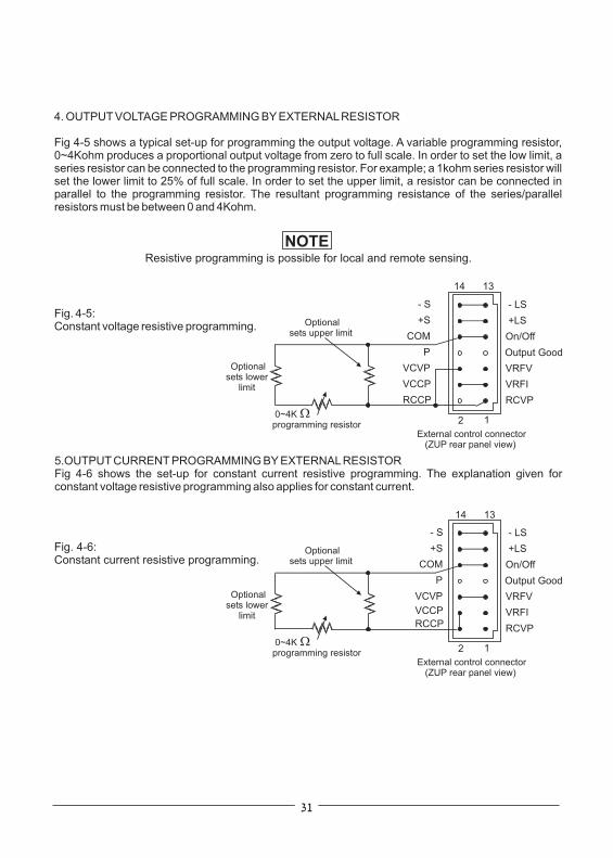
4. OUTPUT VOLTAGE PROGRAMMING BY EXTERNALRESISTOR
Fig 4-5 shows a typical set-up for programming the output voltage. A variable programming resistor,0~4Kohm produces a proportional output voltage from zero to full scale. In order to set the low limit, aseries resistor can be connected to the programming resistor. For example; a 1kohm series resistor willset the lower limit to 25% of full scale. In order to set the upper limit, a resistor can be connected inparallel to the programming resistor. The resultant programming resistance of the series/parallelresistors must be between 0 and 4Kohm.
NOTEResistive programming is possible for local and remote sensing.
Fig. 4-5:Constant voltage resistive programming.
2
2
- LS
- LS
- S
- S
+LS
+LS
+S
+S
On/Off
On/Off
0~4Kprogramming resistor
0~4Kprogramming resistor
Optionalsets lower
limit
Optionalsets lower
limit
Optionalsets upper limit
Optionalsets upper limit
External control connector(ZUP rear panel view)
External control connector(ZUP rear panel view)
COM
COM
P
P
VRFV
VRFV
VCVP
VCVP
VRFI
VRFI
VCCP
VCCP
RCVP
RCVP
RCCP
RCCP
1
1
5.OUTPUT CURRENT PROGRAMMING BY EXTERNALRESISTORFig 4-6 shows the set-up for constant current resistive programming. The explanation given forconstant voltage resistive programming also applies for constant current.
Fig. 4-6:Constant current resistive programming.
Output Good
Output Good
14
14
13
13

4.4.11 Output Voltage Programming by external voltage
4.4.12 Output Current Programming by external voltage
CAUTION
CAUTION
Fig. 4-7 shows the set-up for external voltage programming of the output voltage. A voltage sourcevariable from 0 to 4V, programs the output voltage proportionally from zero to full scale. The static loadcurrent on the programming source is less than 2uA. The source resistance should be less than10Kohm to avoid degradation of offset and drift specifications. When external voltage is used forprogramming the front panel and the computer control (via the serial communication) are disabled.Note: Full scale is 105% of the rated output voltage.
Fig. 4-8 shows the set-up for external voltage programming of the output current. A voltage sourcevariable from 0 to 4V, programs the output current proportionally from zero to full scale. The static loadcurrent on the programming source is less than 2uA. The source resistance should be less than10Kohm to avoid degradation of offset and drift specifications.Note: Full scale is 105% of the rated output current.
The Com pin at the external control connector is connected to the -Sense potential. NEVERconnect the Com pin (pin10) to any potential, as it may damage the power supply.
Avoid connection of resistors greater than 4kohm or voltage greater than 4V for external resistoror voltage programming, as it may cause the output voltage and current to exceed the powersupply rating. The display will NOT show the actual voltage and current when such resistor
or voltage is applied for programming.
Fig. 4-7:Output voltage programmingby external voltage source.
(ZUP rear panel view)
Fig. 4-8:Output current programmingby external voltage source.
(ZUP rear panel view)
0~4VDCVoltagesource
0~4VDCVoltagesource
+
+
_
_
2
2
14
14
- LS
- LS
- S
- S
+LS
+LS
+S
+S
On/Off
On/Off
External control connector
External control connector
COM
COM
P
P
VRFV
VRFV
VCVP
VCVP
VRFI
VRFI
VCCP
VCCP
RCVP
RCVP
RCCP
RCCP
1
1
13
13
Output Good
Output Good

4.4.13 Auto Parallel Operation
4.While operating in CV mode, the master unit regulates the output voltage and the slave units operateas controlled current source, following the master output current. It is recommended to design thepower system so that each unit will supply up to 95% of it’s current rating, because of an imbalancewhich may be caused by cabling and connections voltage drop.
The master unit OVP should be adjusted to the desired OVP level. TheOVP of the slave units should be adjusted higher than the Master OVP. When the master unit shutsdown, it programs the slave units to zero output voltage. If a slave unit shuts down (when it’s OVP isset lower than the master output voltage), only that unit will shut down and remaining slave unitswill supply all the load current.
At auto-parallel mode, power supplies can be connected in local or remotesensing. Refer Fig. 4-9, 4-10 & 4-11 for typical connections of paralleled power supplies. The figurebelow shows connection of two units, however the same connection method applies for up to 5 units.
5. Over Voltage Protection:
6. Connection to the Load:
Fig. 4-9:Auto-parallel with local sensing(ZUP rear panel view)
- V
- V
+V
+V
LOAD
MASTERPOWERSUPPLY
SLAVEPOWERSUPPLY
+
_- LS
- LS
- S
- S
2
2
14
14
1
1
13
13
+LS
+LS
+S
+S
On/Off
On/Off
COM
COM
P
P
VRFV
VRFV
VCVP
VCVP
VRFI
VRFI
VCCP
VCCP
RCVP
RCVP
To
oth
er
sla
ve
s
RCCP
RCCP
NOTEWith local sensing it is important to minimize the wire length and resistance. Also the wires
resistance should be as close as possible to achieve current balance between power supplies.
1.Up to five units of the same rating can be connected in an auto-parallel combination to provide up tofive times the output current capability. One of the power supplies operates as a master and theremaining units as slaves. The slave units are analog programmed by the master unit.At remoteoperation, only the master unit can be programmed by the computer while the slave units may beconnected to the computer for actual voltage and current readback only.
2. Foldback protection if desired, may only be used with the master unit. When the master unit shutsdown it programs the slave units to zero output voltage.
3. Setting the voltage and current:The output voltage of the slave units should be programmed higher than the output and the master toavoid interference with the master CV control. Output voltage of the master should be programmedto the desired voltage, and the current limit to the desired load current divided by the number ofparallel units. During operation, the master unit operates at CV mode and the slave units at CC mode.
Output Good
Output Good

Fig. 4-10: Local sensing withdistribution terminals.(ZUP rear panel view)
Fig. 4-11:Auto parallel withremote sensing
(ZUP rear panel view)
- V
- V
- V
- V
+V
+V
+V
+V
+S
- S
LOAD
LOAD
MASTERPOWERSUPPLY
MASTERPOWERSUPPLY
SLAVEPOWERSUPPLY
SLAVEPOWERSUPPLY
+
+
_
_
- LS
- LS
- S
- S
+LS
+LS
+S
+S
On/Off
On/Off
COM
COM
P
P
VRFV
VRFV
VCVP
VCVP
VRFI
VRFI
VCCP
VCCP
RCVP
RCVPTo
oth
er
sla
ves
RCCP
RCCP
- S
+S
-S+S
- LS
- LS
- S
- S
+LS
+LS
+S
+S
On/Off
On/Off
COM
COM
P
P
VRFV
VRFV
VCVP
VCVP
VRFI
VRFI
VCCP
VCCP
RCVP
RCVP
To
oth
er
sla
ve
s
RCCP
RCCP
Output Good
Output Good
Output Good
Output Good
2
2
2
2
14
14
14
14
1
1
1
1
13
13
13
13

CAUTION
CAUTION
When two power supplies are connected in series, they should be programmed to the same outputvoltage to prevent damage to the lower voltage supply at short circuit condition.
When power supplies are connected in series, and the load or one of the output terminalsis grounded, no point may be at a greater potential ( + or - ) from ground than that specified
on the front panel marking.
4.4.14 Series Operation1. GENERAL: Two power supplies of the same rating can be connected in series to increase the
output voltage or to provide bipolar output voltage.
2. Series connection for increased output voltage:2.1 General: At this operation mode, two units are connected so their outputs are summed. Set the
current limits of each power supply to the maximum that the load can handle without damage. It isrecommended to connect diodes in parallel to each unit output to prevent reverse voltage during start-up condition or in case one of the units shuts down. Each diode should be rated to at least the powersupply’s output current. Refer to Fig: 4-12 and 4-13 for this operating mode.
2.2 Remote programming at series operation for increased output voltage:1. Programming by external voltage; The analog programming circuits of the ZUP power supply
are referenced to the - Sense potential. Therefore, the circuits used to control each unit mustbe separated and floated from each other.
2. Programming by external resistor: Programming by external resistor is possible. Refer toFig. 4-5 and Fig. 4-6 for details.
3. Programming via the communication port (RS232/RS485): The communication port is isolatedfrom the output voltage, therefore power supplies connected in series, can be chained usingthe Remote-in and Remote-out connectors.
Fig. 4-12: Series connection with local sensing. Fig. 4-13: Series connection, remote sensing.
- S - S
- S - S
+LS +LS
+LS +LS
- LS - LS
- LS - LS
+S +S
+S +S
LOAD LOAD
POWERSUPPLY
POWERSUPPLY
POWERSUPPLY
POWERSUPPLY
+ +
+ +
+ +
_ _
_ _
_ _

3. Series connection for bipolar output voltage:3.1 General:At this operation mode, two units are configured as a bipolar voltage/current source. Set
the current limits of each power supply to the maximum that the load can handle without damage. It isrecommended to connect diodes in parallel to each unit output to prevent reverse voltage during start-up condition or in case one of the units shuts down. Each diode should be rated to at least the powersupply’s output current. Refer to Fig. 4-14 for this operating mode.
Fig. 4-14: Series connection for bipolar output
- S
- S
+LS
+LS
- LS
- LS
+S
+S
LOADCOM
POWERSUPPLY
POWERSUPPLY
+
+
+
_
_
_
3.2 Remote programming at series operation for bipolar output voltage:1. Programming by external voltage; The analog programming circuits of the ZUP power supply
are referenced to the - Sense potential. Therefore, the circuits used to control each unit mustbe separated and floated from each other.
2. Programming by external resistor: Programming by external resistor is possible. Refer toFig. 4-5 and Fig. 4-6 for details.
3. Programming via the communication port (RS232/RS485): The communication port is isolatedfrom the output voltage, therefore the serialy connected power supplies can be chained usingthe Remote-In and Remote-Out connectors.

Fig. 4-16: Hierarchical structure inmultiple supply systems.
4.4.15 Output Good Signal
Typical applications of Output Good Signal
Output Good Signal is an open collector output, referenced to COM potential, indicating the status ofthe power supply output. While the power supply operates normally, the Output Good is low (0~0.8V).When the power supply output is disabled due to activated OVP, OTP or FOLD protection, or by OUTset to off, or by ac ON/OFF set to off, then the output signal stops conducting. The maximum sinkcurrent is 10mAand the maximum voltage is 40VDC.
1. In multiple power supply systems, it is possible to disable all the units when a critical unit fails. Referto Fig 4-15 for typical connection diagram.
2. Hierarchical structure in multiple supply systems:It is possible to define a hierarchy in multiple supplysystems by enabling any N+1 unit by the Output Good signal of the N unit. In this structure, failure ofthe N unit will cause all the following units to be disabled. Refer to Fig 4-16 for typical connectionsdiagram.
CAUTIONThe Output Good Signal is referenced to the COM potential, therefore pay attention NOT to
short it to another potential as it may damage the unit.
Fig. 4-15: Disabling multiple supply systems.
- V
- V
For models with output voltage rating greater than 40V usea Zener diode to limit the Output Good voltage below 40V.The resistor and Zener power rating must be greater than themaximum actual power dissipation.
( )*
( )*
( )*
( )*
- V
COM
COM
PCn
PCn
PC1PC1I = 5mA
COM
+V+V
+V
ON/OFF
OUT.GOOD
ON/OFF
ZUP #CriticalZUPUnit # 1
ZUP # n
n
OUT.GOOD
OUT.GOOD
OUT.GOOD
COM
- V
COM- V
COM
PC1-A
PC2-A
PC1-B
PC( -1)-Bn
+V
+V
+V
ON/OFF
ON/OFF
ON/OFF
ZUP # 1
ZUP # 2
ZUP # n

This chapter describes the operation of the ZUP series via the serial communication port. details of theinitial set-up, operation via RS232 or RS485, the command set and the communication protocol aredescribed in this chapter.
The ZUP addresses can be set to any address between 01 and 31. Follow the procedure describedbelow to set the address.1. Momentarily press theADDR pushbutton on the front panel so theADDR LED illuminates and the
VOLTS display shows ‘Addr’.2. Rotate the front panel knob. While rotating the knob theAMPS display will show the selected
address. When the rotation is stopped, the address shown will be the selected address. The displaywill return to show the actual voltage and current approx. 3 sec. from termination of rotating knob.
3. While the unit is in operation, depressing theADDR pushbutton will cause the display to show theselected address.
To select between RS232 or RS485 serial communication the following steps should be taken.1. Press and hold REM pushbutton.(holding REM depressed for more than 1sec does not change the
local/remote status).2. Press and hold REM pushbutton.After approx. 3sec. the display will continuously cycle between
‘rs232’and ‘rs485’approx. every 3sec.3. To select RS232, release the REM pushbutton while ‘rs232 is displayed. To select RS485, release
the REM pushbutton while ‘rs485 is displayed.4.Approx. 3sec after releasing the REM, the display returns to show the actual voltage and current.
Six optional rates are possible:300, 600, 1200, 2400, 4800, 9600. To select the desired rate, thefollowing steps should be taken. The power supply should be at Local operation mode during thefollowing procedure:1. Press and hold ADDR pushbutton.After approx. 3 sec. the display will continuously cycle between
the six optional rates approx. every 2 seconds.2. To select the desired rate, releaseADDR while that rate is displayed.3.After releasingADDR the display will return to show the actual voltage and current.
To enable the operation via RS232 or RS485, the power supply should be at Remote mode. At thismode, all the front panel functions are disabled except Local/Remote pushbutton.Transition from Local to Remote control:1. Via the front panel: Momentarily press REM pushbuttonso the REM LED illuminates. To return from
Remote to Local control, momentarily press REM pushbutton so the REM LED extinguishes.2. Via the serial communication port (RS232/RS485): By sending a :RMTn; command to the power
supply. Refer to par. 5.5.2.
CHAPTER 5 RS232 & RS485 REMOTE CONTROL
5.1 INTRODUCTION
5.2 CONFIGURATION
5.2.1 Address setting
5.2.2 RS232 or RS485 selection
5.2.3 Baud rate setting
5.2.4 Local/Remote selection

5.3 REMOTE PROGRAMMING VIA RS232
5.3.1 Introduction
5.3.2 Rear panel connectors pinout
IN
RXD+
RXD+
TXD+
TXD+
RXD_
RXD_
TXD_
TXD_
Not used
Shield (connector enclosure)
Not used
RX (RS232)
NC
NC
SG
TX(RS232)
SGOUT
RS232
10m max. 1000m max.
RS485 RS485
Fig. 5-1: Linking ZUP units with RS232 control.
The RS232 interface is accessible through the rear panel IN/OUT jacks. The jacks are 8 contacts eachand conform to EIA/TIA-568A requirements. The IN and OUT jacks are used to connect the units in aRS232 or RS458 chain to a controller. The data format isASCII, 8 bits/character no parity bit, one stop bit.The baud rate can be selected to one of the 6 possible rates between 300 and 9600bps (refer topar.5.2.3).Rrefer to par.5.6 for detailed explanation.Up to 31 ZUP units can be connected to the RS232 control as shown in Fig.5-1.
Fig. 5-2:Rear panel connector pinout
(ZUP rear panel view)
87654321
87654321
NOTETx and Rx are used for RS232 communication. Txd +/- and Rxd +/- are used for RS485communication. Refer to RS232 and RS485 cables description for connection details.
ZUP (1) ZUP (2) ZUP (31)

The RS232 is used only for connecting the power supply to the controller PC. For linking several powersupplies, refer to par. 5.3.4.
It is possible to link up to 31 ZUP units, using rear panel In/Out connectors and linking cables as shownin Fig. 5-1. The first unit communicates with the PC via RS232 as shown in Figs. 5-3 and 5-4. The otherunits are linked by RS485 interface. Construction of the linking cable is shown in Fig. 5-5.
5.3.3 RS232 cable ( PC to ZUP ) - ZUP/NC403 , ZUP/NC401
5.3.4 Linking power supplies - ZUP/NC405 / ZUP/W
Fig. 5-3: RS232 cable with DB-25female connector -P/N: NC403
Fig. 5-4: RS232 cable with DB-9female connector -P/N: NC401.
Fig. 5-5: ZUP units linking cable.P/N: ZUP/NC405
ZUP/W
EIA/TIA-568A SHIELDED CONNECTORS
52468
52468
PIN NO.HOUSING HOUSING
PIN NO.NAME NAME
SHIELDSGTXDTXDRXDRXD
SHIELDSGTXDTXDRXDRXD
8 PIN CONNECTOR (IN) 8 PIN CONNECTOR (OUT) REMARKS
235
735
PIN NO.
HOUSING HOUSINGPIN NO.NAME NAME
SHIELDRXTXSG
SHIELDTXRXSG
DB-9 CONNECTOR 8 PIN CONNECTOR REMARKS
TWISTEDPAIR
237
1375
PIN NO. PIN NO.NAME NAME
SHIELDTXRXSG
SHIELDRXTXSG
DB-25 CONNECTOR 8 PIN CONNECTOR REMARKS
TWISTEDPAIR
8
8
1
8
1
1
1
8
5
1
13
1
-+
+
+
+-
--

Fig. 5-7: RS485 cable withDB-9 female connector.
Fig. 5-6: Linking ZUP units to RS485 control.
For operation environments that require high noise immunity or long distance communication, it isrecommended to use the built-in RS485 interface. The RS485 interface is accessible through therear panel In/Out jacks in a similar way to the RS232. The communication is a four-wire type. Refer topar. 5-6 for detailed explanation. Up to 31 ZUP units can be connected to the RS485 control as shownin Fig. 5-6.
Power supplies are linked in the same way as described in par. 5.3.4.
The ZUP command set is divided into four categories as follows: 1. Initialization Control2. ID Control3. Output Control4. Status Control
The commands structure, syntax, and registers definition are described in this paragraph as listedabove.
5.4 REMOTE PROGRAMMING VIA RS485
5.4.1 Introduction
5.4.3 Linking power supplies
5.5 ZUP SERIES COMMAND SET DESCRIPTION
5.4.2 RS485 cable ( PC to ZUP ) - NC402
98154
68524
PIN NO.
HOUSING HOUSING
PIN NO.NAME NAME
TWISTEDPAIR
TWISTEDPAIR
SHIELDTXDTXDSGRXDRXD
SHIELDRXDRXDSGTXDTXD
DB-9 CONNECTOR 8 PIN CONNECTOR REMARKS
-+
+
+
+-
-
-
8
1
5
1
RS485
1000m max.
RS485 RS485
ZUP (1) ZUP (2) ZUP (31)

5.5.2 ID control commands# Commands
1 :MDL?;
2 :REV?;
Description
Returns the power supply model identification as anASCII string:Nemic-Lambda ZUP(XXV)-(YYA).XX - The rated output voltageYY - The rated output currentexample: Nemic-Lambda ZUP(6V-33A)
Returns the software version as anASCII string:Ver XX-YYA.BXX- The rated output voltageYY- The rated output currentA.B- Version identifierexample: Ver 6-33 1.0
5.5.1 Initialization control# Commands
2 :DCL;
1 :ADRn;
3 :RMTn;
4 :RMT?;
Description
Clears the communication buffer and the following registers:1. Operational status register2.Alarm (fault) status register3. Programming error register
Sets the power supply address. ADR is followed by the addresswhich can be 01 to 31.
Sets the power supply to local or remote mode. (This command is activewhen the unit is either in Local or Remote modes).Transition from Local toRemote mode is made via the front panel only.:RMT0; Transition from Remote to Local mode.:RMT1; Transition from latched Remote to non-latched Remote.:RMT2; Latched remote: Transition back to Local mode or to non- latchedRemote can be made via the serial port (RS232/485).At this mode, the front panel Local/Rem function is disabled. Escape fromthis mode to non -latched remote mode can be made by turning the ACON/OFF to OFF and after approx. 10sec.to ON again.
Returns the remote/local setting. The returned data is anASCII string.RM1 (The unit is in remote mode)RM2 (The unit is in latched remote mode)

5.5.3 Output control# Commands
1 :VOLn;
2 :VOL!;
Description
Sets the output voltage value in volts. This programmed voltage is theactual output at constant-voltage mode or the voltage limit at constantcurrent mode. The range of the voltage values are as shown in table 5-1.Use all digits for voltage programming
Returns the string (Set Voltage) followed by the present programmedoutput voltage value. The actual voltage range is as shown in table 5-1.example: SV5.010 SV08.500
SV
Note:The ZUP can accept programmed valuehigher by up to 5% than the table values,however it is not recommended to programpower supply over the rated voltage.
Table 5-1: Voltage programming range.
Example - ZUP6-XY :VOL5.010; ZUP10-XY :VOL08.500;
Example - ZUP60-3.5 :CUR3.000; ZUP10-40 :CUR07.50;
Model MIN. MAX.
ZUP6-XY 0.000 6.000
ZUP10-XY 00.000 10.000
ZUP20-XY 00.000 20.000
ZUP36-XY
ZUP80-XY
00.00
00.00
36.00
80.00
ZUP60-XY
ZUP120-XY
00.00
000.00
60.00
120.00
4 :CURn;
3 :VOL?;
Sets the output current in Ampers. This programmed current is the actualoutput current at constant-current mode or the current limit at constantvoltage mode. The programming range is shown in table 5-2:Use all digits for current programming.
Returns the string (Actual Voltage) followed by the actual output voltage.The actual voltage range is the same as the programming range.example: AV5.010 AV08.500
AV
Note:The ZUP can accept values higher by 5%than the rating. It is recommended to set theoutput current to 105% of the rating if theunit is required to supply the rated current.
Model MIN. MAX.
ZUP6-33 00.00 33.00
ZUP6-66 00.00 66.00
ZUP6-132 000.00 132.00
ZUP10-20 00.000 20.000
ZUP10-40
ZUP10-80
ZUP20-10
ZUP20-20
ZUP20-40
ZUP36-6
ZUP36-12
00.00
00.00
00.000
00.000
00.00
0.000
00.000
40.00
80.00
10.000
20.000
40.00
6.000
12.000
ZUP36-24
ZUP60-3.5
ZUP60-7
ZUP60-14
00.000
0.000
0.000
00.000
24.000
3.500
7.000
14.000
ZUP80-2.5
ZUP80-5
ZUP120-1.8
ZUP120-3.6
0.0000
0.000
0.0000
0.000
2.5000
5.000
1.8000
3.600
Table 5-2: Current programming range.

5.5.3 Output control continued
# Commands
5 :CUR!;
6 :CUR?;
7 :OUTn;
8 :OUT?;
9 :FLDn;
10 :FLD?;
Description
Returns the string (Set Amper) followed by the present programmedoutput current. The programmed value range is shown in table 5-2.example- SA3.000 SA07.50
SA
Returns the string (Actual Amper) followed by the actual output current.The actual current range is the same as the programming range.example- AA3.000 AA07.50
AA
Sets the output to On or Off.:OUT1; - Output On:OUT0; - Output Off
Returns followed by the output On/Off status.OT1 - Output is OnOT0 - Output is Off
OT
Sets the Foldback protection to On or Off.:FLD1; Arm the foldback protection.:FLD0; Release the foldback protection.:FLD2; Cancel the foldback protection.When the foldback protection is activated, :FLD0; will release theprotection and re-arm it while :FLD2; will cancel the protection. If theprotection has not been activated, both commands are the same.
Returns followed by the Foldback protection status.FD1 - Foldback is armedFD0 - Foldback is released
FD
11 :OVPn;
12 :OVP?;
Sets the over-voltage protection level in volts. Over-voltage range settingsare given in table 5-3:
Example - ZUP10-XY :OVP08.4;
Example- OP08.4
Returns the string followed by the present programmed over-voltageprotection value. The over-voltage range is given in table 5-3.
OP
Model MIN. MAX.
ZUP6-XY 0.20 7.50
ZUP10-XY 00.5 13.0
ZUP20-XY 01.0 24.0
Table 5-3: Over-voltage programming range.
ZUP36-XY 01.8 40.0
ZUP60-XY 03.0 66.0
ZUP80-XY 04.0 88.0
ZUP120-XY 006.0 132.0

5.5.3 Output control continued# Commands
13 :UVPn;
Description
Sets the under-voltage protection limits in volts. Under-voltage rangesettings are given in table 5-4:
Model MIN. MAX.
ZUP6-XY 0.00 5.98
ZUP10-XY 0.00 9.97
ZUP20-XY 00.0 19.9
14 :UVP?;
15 :ASTn;
16 :AST?;
Example - ZUP20-XY :UVP07.3;
example- UP07.3
Returns the string followed by the present programmed under-voltageprotection value. The under-voltage range is given in table 5-4.
UP
Sets the auto-restart mode to On or Off.:AST1; -Auto-restart is On:AST0; -Auto-restart is Off
Returns the string followed by the auto-restart mode status.AS1 -Auto-restart is ONAS0 -Auto-restart is Off
AS
Table 5-4: Under-voltage programming range.
ZUP36-XY 00.0 35.9
ZUP60-XY 00.0 59.8
ZUP80-XY 00.0 79.8
ZUP120-XY 000.0 119.8
1. Operational Status Register:The operational status register records signals that are part of the power supply’s normal operation. Inaddition to the normal operation data, the register holds an alarm bit which indicates that one of thealarm (fault) register bits is set. The register is automatically updated and reading it does not change it’scontent. Clearing the register is done by DCL command. See table 5-5 for Operational Status Registercontent.
Note:*1 In case ofAC fail, the alarm status register ‘AC fail’ bit will be set but will not set the alarm bit.
5.5.4 Status control
5.5.4.1 Registers structure
Table 5-5: Operational status register content.
Bit Name Bit No Meaningcc/cv 1 ‘0’ - Indicates constant voltage, ‘1’ - constant current.
‘1’ - Indicates auto-restart is on, ‘0’ - auto-restart is off.
‘0’ - Indicates foldback protection SRQ is disabled , ‘1’ - enabled.
‘0’ - Indicates over voltage protection SRQ is disabled , ‘1’ - enabled.
‘1’ - Indicates output is on , ‘0’ -output is off.
‘0’ - Indicates over temp. protection SRQ is disabled , ‘1’ - enabled.
‘1’ - Indicates foldback protection is armed.fold 2ast 3out 4srf 5srv
srt
alarm
6
8
7
‘1’ - Indicates that an alarm register bit is set. (note*1)

Bit Name
Bit Name
Bit No
Bit No
Meaning
(*3)
(*3)
(*1)
(*2)
(*3)
Meaning
ovp
not used
‘1’ - Indicates that the over-voltage protection was tripped
‘1’ - Indicates that a failure occurred at the input voltage supply
‘1’ - Indicates an overflow in the communication buffer
‘1’ - Indicates that the foldback protection was activated
‘1’ - Indicates an attempt to program the power supply to a voltageout of specification limits.
‘1’ - Indicates an attempt to program the power supply to a currentout of specification limits.
‘1’ - Indicates a programming error has occurred
‘1’ - Indicates that the over-temperature protection was tripped
‘1’ - Indicates that an unknown string was received
otp
wrong command
a/c fail
buffer overflow
fold
wrong voltage
prog
wrong current
Table 5-6: Alarm status register content.
Table 5-7: Error codes register content.
2.Alarm Status Register:The alarm status register records fault conditions occurring during power supply operation. Any set bitin this register causes the ‘alarm’ bit in the operational status register to be set. Reading the registerdoes not change it’s content. The register is cleared by :DCL; command.
3. Error Codes Register:The error codes register records errors that occurred during the programming of the power supply.Anyset bit in this register causes the ‘prog’ bit in the alarm status register to be set. Reading the registerdoes not change it’s content. The register is cleared by :DCL; command.
Notes: (*1) Since at eachAC turn off theAC fail bit is generated and stored, it is recommended tosend a :DCL; command following application ofAC voltage to the power supply, to clear thealarm status register.
(*2) FOLD bit is automatically reset upon cancellation of FOLD protection.(*3) OVP, OTP and ‘prog’bits reset atAC turn-off or by :DCL; command.
1
1
2
2
3
3
4
4
5
5
5.5.4.2 Status control commands# Commands
1 :STA?;
2 :ALM?;
Description
Reads the operational status register content.Returns the string followed by ASCII characters representing theregister’s content.Refer to table 5-5 for the register content description.example- OS00010000
OS
Reads the alarm status register content.Returns the string AL followed by ASCII characters representing theregister’s content.Refer to table 5-6 for the register content description.example- AL00000
In case the OTP or OVP is triggered, the front panel control is disabled until theAC input isrecycled by turning theAC ON/OFF switch to OFF and after approx. 10 sec. to ON.

5.5.4.2 Status control commands continued# Commands
3 :STP?;
4 :STT?;
Description
Reads the programming error register content.Returns the string followed by ASCII characters representing theregister’s content.Refer to table 5-7 for the register content description.example- PS00000
PS
Reads the complete status of the power supply.This query returnsASCII characters representing the following data:AV<actual voltage >SV<voltage setting>AA<actual current>SA<current setting>OS<operational status register>AL<alarm status register>PS<programming error register>
example:AV5.010SV5.010AA00.00SA24.31OS00010000AL00000PS00000
5.6 COMMUNICATION PROTOCOL
5.6.1 General Information
5.6.2 Accessing a ZUP Unit
5.6.3 End of Message
The average command processing time of the ZUP Series is 15mSec. It is not recommended to sendstrings of commands to the ZUP power supply without considering the processing time.For query commands ( ? , ! ) , wait until the ZUP reply message has been completed , before sending anew command.
The default condition of the ZUP series is Listen mode. In order to access a ZUP unit, for sending acommand or query, the address of that unit should be sent by the host controller (:ADRn;). The ZUP thatrecognizes it’s address becomes active and can communicate with the host controller. The other unitsremain in Listen mode, waiting to receive their address. To access another unit, the controller shouldsend the address of that unit. The previously active unit changes it’s state to Listen mode and theaddressed unit becomes active.
The messages generated by the ZUP are terminated by an end of message:< CR > carriage return character< LF > line feed character
When sending a message to the ZUP, there is no need for the end of message characters.

48
5.6.4. COMMUNICATION TEST SET UP
1. Equipment :
2. PC Set Up :
3. ZUP Set Up
4. Communicationtest
ATTENTION:
PC with Windows HyperTerminal Private Edition software installed , ZUP PowerSupply , RS232 cable (NC401 when the PC uses DB-9 or NC403 when the PC usesDB-25 connector).
Open Hyper Terminal Private Edition...... New Connection
Enter a name
Connect to...................... Direct to Com1 or Com2
Set the Port Properties as follows:
Bits per second...................... 9600
Data bits...................................... 8
Parity.................................... None
Stop bits....................................... 1
Flow control..................... Xon/Xoff
Open Properties in the program:
File:............... PropertiesSetting: ASCII Set Up
select Echo characters locally
Press for capital letters
Connect ZUP Power Supply to the PC using RS232 cable (NC401 or NC403)
Set via the front panel: Baud Rate 9600, RS232/RS485 to RS232, address:01
Set Rem/Local to Rem (Rem LED illuminates)
Model identification test:PC: writeZUP response:
Command test:PC: write: (for n refer 5.5.3)
The ZUP output should turn on and display will show the output voltage and actualoutput current.
Do not use Backspace, Enter, Ctrl or Alt keys.If an error was made during writing , press “;” and write again the command.
2.1
2.2
2.3
2.4
2.5
2.6
2.7 Caps Lock
3.1
3.2
3.3
4.1:ADR01;:MDL?;Nemic-Lambda<XXV-YYA>
4.2:OUT1; :VOLn; :CURn;

Service request is a message generated by the ZUP power supply to interrupt the controller. SRQcan be generated by a power supply fault condition.Each of the following conditions can generate SRQ message:1. Over Voltage Protection (OVP).2. Over Temperature Protection (OTP).3. Foldback Protection.The operator decides which of the conditions are defined as faults. Enabling or disabling a conditionfrom generating SRQ message does not affect the condition within the power supply.
The service request message consists of three characters terminated by EOS<CR><LF>.The first character identifies the SRQ cause: 1-Foldback , 2-OVP , 3-OTP.The 2’nd and 3’rd characters identify the ZUP power supply address.
Example: String generated by a ZUP unit :120<CR><LF> , means foldback protection was activatedin power supply address 20.
5.7 SERVICE REQUEST
5.7.1 Service Request (SRQ)
5.7.2 Service Request message
5.7.3. Service request enable/disable commands
49
# Command Description
1 :SRVn; Enable or disable OVP service request.:SRV1; Enable OVP service request.:SRV0; Disable OVP service request.
2 :SRV?; Returns QV followed by the OVP service request status.:QV1; OVP service request enabled.:QV0; OVP service request disabled.
3 :SRTn; Enable or disable OTP service request.:SRT1; Enable OTP service request.:SRT0; Disable OTP service request.
4 :SRT?; Returns QT followed by the OTP service request status.:QT1; OTP service request enabled.:QT0; OTP service request disabled.
5 :SRFn; Enable or disable Foldback protection service request.:SRF1; Enable Foldback protection service request.:SRF0; Disable Foldback protection service request.
6 :SRF?; Returns QF followed by the Foldback protection service request status:QF1; Foldback protection service request enabled.:QF0; Foldback protection service request disabled.

This chapter contains maintenance and calibration information for the ZUP power supply series.
Units requiring repair during the warranty period should be returned to a Nemic-Lambda authorizedservice facility. Refer to the address listing on the back cover of this user’s manual. Unauthorizedrepairs performed by other than authorized service facilities may void the warranty.
No routine maintenance of the ZUP power supply is required except for periodic cleaning. To clean,disconnect the unit from theAC supply and allow 30sec for discharging internal voltage. The front paneland the metal surfaces should be cleaned using a dry cloth. Use low pressure compressed air to blowdust from the unit.
No internal adjustment or calibration are required. Units that are returned for service will be calibratedat the service facility. There is NO REASON to open the ZUP cover.
As repairs are made only by the manufacturer of authorized service facilities, no part replacementinformation will be discussed here. In case of failure, unusual or erratic operation of the unit, contact aNemic-Lambda sales or service facility nearest you. Please refer to the Nemic-Lambda sales officeslisted on the back cover of this user’s manual.
ZUP200 Series(ZUP6-33,ZUP10-20,ZUP20-10,ZUP36-6,ZUP60-3.5,ZUP80-2.5,ZUP120-1.8) : T8A250VZUP400 Series(ZUP6-66,ZUP10-40,ZUP20-20,ZUP36-12,ZUP60-7,ZUP80-5,ZUP120-3.6) : T10A250VZUP800 Series (ZUP6-132, ZUP10-80, ZUP20-40, ZUP36-24, ZUP60-14): F20A250V
CHAPTER 6 MAINTENANCE
6.1 INTRODUCTION
6.2 UNITS UNDER WARRANTY
6.3 PERIODIC MAINTENANCE
6.4 ADJUSTMENT AND CALIBRATION
6.5 PART REPLACEMENT AND REPAIRS.
6.6 FUSE RATINGS

28
23
41
39
13
46
ac cables
ac fail
accessories
address
adjustment
alarm status
amps display
auto-parallel
automatic start
baud rate
bipolar voltage
buffer overflow
last setting memory
linking power supplies
local/remote
local sensing
rack mounting
remote sensing
registers structure
RS232
RS485
RXD
RX (RS232)
safe start
safety symbols
series operation
shield
status control
SRQ
operational status
otp
output good
over voltage
error code
external resistor
external voltage
grounding
humidity
Hyper Terminal
jacks (front panel) under voltage
volts display
multiple loads
maintenance
parallel operation
parity
ID control
initialization
TXD
TX (RS232)
wire size
wrong command
foldback
fuse
display
calibration
communication
constant current
constant voltage
cooling
cv indicator
cc indicator
6
46
6
24,26,38
50
46
23
33
30
38
36
46
30
40
38, 23
14
12
15
45
38, 39
38, 41
41
39
30
3
35
39, 40, 41
45
49
45
46
37
28
46
31
32
2
8
48
21
15, 16
50
33
48
42
42
23, 29
2, 50
23
50
47
27
27
12
23
23
ZERO-UP USER’S MANUAL INDEX
A
B
L
R
S
O
E
G
H
J U
V
M
P
I T
W
F
D
C

ZERO-UP 200W/400W/800WProgrammable DC Power Supplies Constant Voltage/Constant Current
Built-in RS-232 & RS-485 Interfacewith GPIB option.
ZERO-UP 200W/400W/800WProgrammable DC Power Supplies IA
549-
04-0
1 R
ev N
AD07
12
TDK-Lambda EMEAwww.emea.tdk-lambda.com
USER’S MANUAL
NORTH AMERICATDK-Lambda Americas Inc. 3055 Del Sol Boulevard San Diego, CA 92154 U.S.A.Tel: +1-619-575-4400 Fax: +1-619-575-7185www.us.tdk-lambda.com/lp
UK
TDK-Lambda UK Ltd.Kingsley Avenue Ilfracombe, DevonEX 34 8ES United KingdomTel: +44-1271-856666 Fax: +44-1271-864894E-mail: [email protected]
FRANCE
TDK-Lambda France SASZAC des Delaches BP 1077 - Gometz le Chatel 91940 LES ULIS Tel: +33 1 60 12 71 65 Fax: +33 1 60 12 71 66 E-mail: [email protected]
GERMANY
TDK-Lambda Germany GmbHKarl-Bold-Str.40,D-77855 Achern, GermanyTel: +49-7841-666-0 Fax: +49-7841-500-0E-mail: [email protected]
AUSTRIA
TDK-Lambda Austria Sales OfficeAredstrasse 22,A - 2544 Leobersdorf, AustriaTel: +43-2256-65584 Fax: +43-2256-64512E-mail: [email protected]
ITALY
TDK-Lambda Italy Sales OfficeVia dei Lavoratori 128/130IT20092 Cinisello Balsamo, Milano, ItalyTel: +39-02-6129-3863 Fax: +39-02-6129-0900E-mail: [email protected] www.it.tdk-lambda.com
ISRAEL
TDK-Lambda Ltd.Sales Office: Kibbutz Givat Hashlosha Tel-Aviv 4880000, IsraelTel: +972-3-9024-333 Fax: +972-3-9024-777Plant: 56 Haharoshet St. Karmiel Industrial Zone 2165158, IsraelTel: +972-4-9887-491 Fax: +972- 4-9583-071www.tdk-lambda.co.il E-mail: [email protected]
JAPAN
TDK-Lambda CorporationInternational Sales DivisonNittetsu Bldg. 6F, 1-13-1 Nihonbashi, Chuo-ku, Tokyo 103-0027, JapanTel: +81-3-5201-7175 Fax: +81-3-5201-7287www.tdk-lambda.com
CHINA
Shanghai Branch of Wuxi TDK-Lambda Electronic Co. Ltd.28F, Xingyuan Technology Building No.418, Guiping Road,Shanghai, China 200233Tel: +86-21-6485-0777 Fax: +86-21-6485-0666www. cn.tdk-lambda.comBeijing Branch of Wuxi TDK-Lambda Electronic Co. Ltd.Room 12B11-12B12, Unit 7 DACHENG SQUARE, No.28 Xuanwumenxi Street, Xuanwu District Beijing, 100053, CHINA Tel: +86-10-6310-4872 Fax: +86-10-6310-4874www. cn.tdk-lambda.comShenzhen Branch of Wuxi TDK-Lambda Electronics Co.Ltd.Room 4302, Excellence Times Square Building,4068 Yi Tian Road, Futian District,Shenzhen, China 518048Tel: +86 -755-83588261 Fax: +86 -755-83588260www. cn.tdk-lambda.com
KOREA
TDK-Lambda Corporation Seoul Office8F Songnam Bldg, 1358-6, Seocho-Dong,Seocho-Gu, Seoul, 137-862 KOREATel: +82-2-3473-7051 Fax: +82-2-3472-9137www.tdk-lambda.co.krwww.tdk-lambda.co.krSINGAPORE
TDK-Lambda Singapore Pte.Ltd.Blk 1008 Toa Payoh North # 07-01/03Singapore 318996Tel: +65-6251-7211 Fax: +65-6250-9171www.tdk-lambda.com.sg
INDIA
TDK-Lambda Bangalore Office#526, Ground Floor, 10th Main, 7th Cross,Jeevanbhimanagar , Bangalore 560 075Karnataka, India Tel: +91-80-43550 550 Fax: +91-80-43550 501www.tdk-lambda.com.sg
MALAYSIA
TDK-Lambda Malaysia Sdn. Bhd.c/o TDK (Malaysia) Sdn BhdLot 709, Nilai Industrial Estate 71800 NilaiNegeri Sembilan, MalaysiaTel: + 60 6-799 1130 Fax: + 60 6 799 3277www.tdk-lambda.com.my