790 system planning ver.2.6 120413
DESCRIPTION
Nurse callingTRANSCRIPT
Jeron Electronic Systems, Inc. 1743-55 W. Rosehill Drive Chicago, IL 60660(773) 275-1900 U.S.A. & Canada: (800) 621-1903 Fax: (773) 275-0283 www.jeron.com
AddendumProvider 790 Nurse Call System
System Planning GuideVersion 2.6- 12/04/13
The current version includes the following updates:
• Pg. 6-11: Update maximum cable length in 796x Console Controller table to 700 ft. between Controller and Nurse Console/Terminal.

.
Provider® 790 Nurse Call SystemSystem Planning Guide
Version 2.6 - 12/04/13
Jeron Electronic Systems, Inc. 1743-55 W. Rosehill Drive Chicago, IL 60660(773) 275-1900 U.S.A. & Canada: (800) 621-1903 Fax: (773) 275-0283 www.jeron.com

.

Proprietary InformationThe information contained herein is the proprietary property of Jeron Electronic Systems, Inc. Recipient, by accepting this information agrees that neither this document nor the information contained herein shall be reproduced or transferred to other documents or disclosed to others for manufacturing or any other purpose except as authorized in writing by Jeron Electronic Systems, Inc.
About this ManualThis document is based on information available at the time of its writing. While efforts have been made to be accurate, the information contained herein does not purport to cover all details or variations in hardware or software, or to provide for every possible contingency in connection with installation, operation, or maintenance. Jeron Electronic Systems, Inc. assumes no obligation of notice to holders of this document with respect to changes subsequently made.
Jeron Electronic Systems, Inc. makes no representation or warranty, expressed, implied, or statutory with respect to, and assumes no responsibility for the accuracy, completeness, sufficiency, or usefulness of the information contained herein. No warranties of merchantability or fitness for purpose shall apply.
Copyright InformationAll information resident in this document is considered copyrighted.
The Jeron products described in this instruction manual may include copyrighted Jeron computer programs stored in semiconductor memories or other mediums. Laws in the United States and foreign countries preserve for Jeron certain exclusive rights to copy or reproduce in any form the copyrighted computer program. Accordingly, any copyrighted Jeron computer programs contained in the Jeron products described in this instruction manual may not be copied or reproduced in any manner without the express written permission of Jeron Electronic Systems, Inc. Furthermore, the purchase of Jeron products shall not be deemed to grant either directly or by implication, estoppel, or otherwise, any license under the copyrights, patents or patent applications of Jeron, except for the normal non-exclusive, royalty free license to use that arises by operation of law in the sale of a product.
JERON® is a registered trademark of Jeron Electronic Systems, Inc.
© 2013 by Jeron Electronic Systems, Inc., All Rights Reserved
© 2013 Jeron Electronic Systems Inc. i

Provider 790 Nurse Call System
.
ii © 2013 Jeron Electronic Systems Inc.
ContentsChapter 1: System Architecture
Introduction . . . . . . . . . . . . . . . . . . . . . . . . . . . . . . . . . . . . . . . . . . . . 1-1In this Manual . . . . . . . . . . . . . . . . . . . . . . . . . . . . . . . . . . . . . . . . . . . . . . . . . 1-1Capabilities . . . . . . . . . . . . . . . . . . . . . . . . . . . . . . . . . . . . . . . . . . . . . . . . . . . 1-1Jeron IP Network & Facility LAN . . . . . . . . . . . . . . . . . . . . . . . . . . . . . . . . . . 1-2
System Architecture . . . . . . . . . . . . . . . . . . . . . . . . . . . . . . . . . . . . . 1-3Overview . . . . . . . . . . . . . . . . . . . . . . . . . . . . . . . . . . . . . . . . . . . . . . . . . . . . . 1-3Jeron Nurse Call Buses . . . . . . . . . . . . . . . . . . . . . . . . . . . . . . . . . . . . . . . . . 1-4
J Bus . . . . . . . . . . . . . . . . . . . . . . . . . . . . . . . . . . . . . . . . . . . . . . . . . . . . . . 1-4R Bus. . . . . . . . . . . . . . . . . . . . . . . . . . . . . . . . . . . . . . . . . . . . . . . . . . . . . . 1-4P Bus . . . . . . . . . . . . . . . . . . . . . . . . . . . . . . . . . . . . . . . . . . . . . . . . . . . . . . 1-4M Bus. . . . . . . . . . . . . . . . . . . . . . . . . . . . . . . . . . . . . . . . . . . . . . . . . . . . . . 1-4
System Capacity . . . . . . . . . . . . . . . . . . . . . . . . . . . . . . . . . . . . . . . . . . . . . . . 1-4Single Gateway J Bus . . . . . . . . . . . . . . . . . . . . . . . . . . . . . . . . . . . . . . . . . 1-5Maximum Gateways . . . . . . . . . . . . . . . . . . . . . . . . . . . . . . . . . . . . . . . . . . 1-5Single Nurse Call Isolated 8 Port Ethernet Switch. . . . . . . . . . . . . . . . . . . . 1-5Multiple Nurse Call Isolated 8 Port Ethernet Switch . . . . . . . . . . . . . . . . . . 1-5Room Controllers. . . . . . . . . . . . . . . . . . . . . . . . . . . . . . . . . . . . . . . . . . . . . 1-5Console (Master) Controller. . . . . . . . . . . . . . . . . . . . . . . . . . . . . . . . . . . . . 1-5Power Supply. . . . . . . . . . . . . . . . . . . . . . . . . . . . . . . . . . . . . . . . . . . . . . . . 1-5
System Types . . . . . . . . . . . . . . . . . . . . . . . . . . . . . . . . . . . . . . . . . . . 1-5Audio Visual . . . . . . . . . . . . . . . . . . . . . . . . . . . . . . . . . . . . . . . . . . . . . . . . . . 1-5Audio Visual with Integrations. . . . . . . . . . . . . . . . . . . . . . . . . . . . . . . . . . . . 1-6Tone Visual . . . . . . . . . . . . . . . . . . . . . . . . . . . . . . . . . . . . . . . . . . . . . . . . . . . 1-6
Getting Started . . . . . . . . . . . . . . . . . . . . . . . . . . . . . . . . . . . . . . . . . . 1-6Chapter 2: Equipment Closet
Overview . . . . . . . . . . . . . . . . . . . . . . . . . . . . . . . . . . . . . . . . . . . . . . . 2-1Gateways. . . . . . . . . . . . . . . . . . . . . . . . . . . . . . . . . . . . . . . . . . . . . . . 2-2
Model 7992/93 Nurse Call Gateway . . . . . . . . . . . . . . . . . . . . . . . . . . . . . . . . 2-2Power Supply . . . . . . . . . . . . . . . . . . . . . . . . . . . . . . . . . . . . . . . . . . . 2-5
Model 7995 Power Supply with Battery Backup . . . . . . . . . . . . . . . . . . . . . 2-5Connecting Gateway & Power Supply . . . . . . . . . . . . . . . . . . . . . . . 2-6
Power Supply Requirements Per Gateway. . . . . . . . . . . . . . . . . . . . . . . . . . 2-6By Number of J Bus Devices (Prism Dome Lights) . . . . . . . . . . . . . . . . . . . 2-6For 7967-P Terminal Intercom Operation Only (No Dome Lights) . . . . . . . 2-6Multiple Power Supplies on One Gateway . . . . . . . . . . . . . . . . . . . . . . . . . 2-7Supplemental Power Wire . . . . . . . . . . . . . . . . . . . . . . . . . . . . . . . . . . . . . . 2-8
Chapter 3: HallwaysHallway J Bus Devices. . . . . . . . . . . . . . . . . . . . . . . . . . . . . . . . . . . . 3-1
Room Controllers . . . . . . . . . . . . . . . . . . . . . . . . . . . . . . . . . . . . . . . . . . . . . . 3-2
© 2013 Jeron Electronic Systems Inc. 1
Model 7950 Room Controller. . . . . . . . . . . . . . . . . . . . . . . . . . . . . . . . . . . . 3-2Model 7951 Room Controller and Two Color Dome Lights . . . . . . . . . . . . . 3-2Model 7952 Room Controller and Six Color Dome Lights . . . . . . . . . . . . . . 3-2Associated Equipment for Room Controllers . . . . . . . . . . . . . . . . . . . . . . . 3-4
Console Controllers . . . . . . . . . . . . . . . . . . . . . . . . . . . . . . . . . . . . . . . . . . . . 3-5Model 7960 Console Controller . . . . . . . . . . . . . . . . . . . . . . . . . . . . . . . . . . 3-5Model 7961 Console Controller and Two Color Zone Light. . . . . . . . . . . . . 3-5Model 7962 Console Controller and Six Color Zone Light. . . . . . . . . . . . . . 3-5Model 7963 Console Controller and Prism Zone Light . . . . . . . . . . . . . . . . 3-6Associated Equipment for Console Controllers . . . . . . . . . . . . . . . . . . . . . 3-6
Zone Controllers . . . . . . . . . . . . . . . . . . . . . . . . . . . . . . . . . . . . . . . . . . . . . . . 3-7Model 7971 Two Color Zone Light. . . . . . . . . . . . . . . . . . . . . . . . . . . . . . . . 3-7Model 7972 Six Color Zone Light . . . . . . . . . . . . . . . . . . . . . . . . . . . . . . . . 3-7Model 7973 Prism Zone Light . . . . . . . . . . . . . . . . . . . . . . . . . . . . . . . . . . . 3-8Associated Equipment for Zone Lights . . . . . . . . . . . . . . . . . . . . . . . . . . . . 3-8
Chapter 4: Patient Rooms & Staff StationsOverview of Patient Stations. . . . . . . . . . . . . . . . . . . . . . . . . . . . . . . 4-1Audio R Bus Stations. . . . . . . . . . . . . . . . . . . . . . . . . . . . . . . . . . . . . 4-3
Patient Room Audio Stations. . . . . . . . . . . . . . . . . . . . . . . . . . . . . . . . . . . . . 4-3Private Room. . . . . . . . . . . . . . . . . . . . . . . . . . . . . . . . . . . . . . . . . . . . . . . . 4-5Semi-Private Room . . . . . . . . . . . . . . . . . . . . . . . . . . . . . . . . . . . . . . . . . . . 4-6Ward . . . . . . . . . . . . . . . . . . . . . . . . . . . . . . . . . . . . . . . . . . . . . . . . . . . . . . 4-8Associated Equipment for Patient Stations . . . . . . . . . . . . . . . . . . . . . . . . . 4-8Customizable Button Labels on Audio Stations. . . . . . . . . . . . . . . . . . . . . . 4-8Relays on Patient Stations for Light Controllers . . . . . . . . . . . . . . . . . . . . . 4-9
Staff Areas . . . . . . . . . . . . . . . . . . . . . . . . . . . . . . . . . . . . . . . . . . . . . . . . . . . 4-10Model 7912 Staff Station . . . . . . . . . . . . . . . . . . . . . . . . . . . . . . . . . . . . . . 4-10Model 7916 PA Page Interface . . . . . . . . . . . . . . . . . . . . . . . . . . . . . . . . . 4-11Model 7917 Visual Duty Station. . . . . . . . . . . . . . . . . . . . . . . . . . . . . . . . . 4-12Model 7927 Staff/Duty Station . . . . . . . . . . . . . . . . . . . . . . . . . . . . . . . . . . 4-13Associated Equipment for Staff Audio Stations . . . . . . . . . . . . . . . . . . . . . 4-13
Patient & Facility Bathrooms . . . . . . . . . . . . . . . . . . . . . . . . . . . . . . . . . . . . 4-14Model 7919 Pullcord & Pushbutton Bath Station (with Audio). . . . . . . . . . 4-14Associated Equipment for Bath Stations . . . . . . . . . . . . . . . . . . . . . . . . . . 4-15
Utility Rooms. . . . . . . . . . . . . . . . . . . . . . . . . . . . . . . . . . . . . . . . . . . . . . . . . 4-16Model 7918 Electrical Supervision Station . . . . . . . . . . . . . . . . . . . . . . . . 4-16
Peripheral P Bus Stations . . . . . . . . . . . . . . . . . . . . . . . . . . . . . . . . 4-17Patient Rooms & Staff Areas . . . . . . . . . . . . . . . . . . . . . . . . . . . . . . . . . . . . 4-17
Model 7934 Staff Presence Station . . . . . . . . . . . . . . . . . . . . . . . . . . . . . . 4-18Model 7937 Remote Cancel Station . . . . . . . . . . . . . . . . . . . . . . . . . . . . . 4-19Model 7940 Procedure, Presence, and Bed Management Station . . . . . . 4-20Associated Equipment for Staff Presence & Procedure, Presence, and Bed Management Stations . . . . . . . . . . . . . . . . . . . . . . . . . . . . . . . . . . . . . . . . 4-20Model 7941 Dual Auxiliary Alarm Input Station . . . . . . . . . . . . . . . . . . . . . 4-21Model 7945 Dual External Alarm Input Station . . . . . . . . . . . . . . . . . . . . . 4-22
2 © 2013 Jeron Electronic Systems Inc.
Associated Equipment for Auxiliary Input Stations . . . . . . . . . . . . . . . . . . 4-22Model 7947 8 Input Bed Interface . . . . . . . . . . . . . . . . . . . . . . . . . . . . . . . 4-23
Patient or Facility Bathroom & Shower. . . . . . . . . . . . . . . . . . . . . . . . . . . . 4-24Model 7932 Pullcord & Pushbutton Station . . . . . . . . . . . . . . . . . . . . . . . . 4-24Model 7958 Shower Station. . . . . . . . . . . . . . . . . . . . . . . . . . . . . . . . . . . . 4-25-R Relay Option for 7932 Pullcord & Pushbutton Station or 7958 Shower Station. . . . . . . . . . . . . . . . . . . . . . . . . . . . . . . . . . . . . . . . . . . . . . . . . . . . . . . . . . 4-25Associated Equipment for Pullcord & Pushbutton Station & Shower Station4-25
Other Facility Rooms . . . . . . . . . . . . . . . . . . . . . . . . . . . . . . . . . . . . . . . . . . 4-26Model 7930 Single Pushbutton Station . . . . . . . . . . . . . . . . . . . . . . . . . . . 4-26Model 7931/7931-P Dual Pushbutton Station . . . . . . . . . . . . . . . . . . . . . . 4-27Model 7949/7949-P Code Blue/Code Pink Station . . . . . . . . . . . . . . . . . . 4-28-R Relay Option for 7931 and 7949 Stations . . . . . . . . . . . . . . . . . . . . . . . 4-28
Peripheral Station Configuration Options . . . . . . . . . . . . . . . . . . . . . . . . . 4-29Customizable Call Button Labels on Peripheral Stations . . . . . . . . . . . . . 4-29Call Types & Indications. . . . . . . . . . . . . . . . . . . . . . . . . . . . . . . . . . . . . . . . 4-29
Patient Room Equipment. . . . . . . . . . . . . . . . . . . . . . . . . . . . . . . . . 4-34Pillow Speakers for DIN Jack Patient Stations. . . . . . . . . . . . . . . . . . . . . . 4-34
Model 7901 Standard Pillow Speaker . . . . . . . . . . . . . . . . . . . . . . . . . . . . 4-34Model 7902 Standard Pillow Speaker with Two Aux Buttons . . . . . . . . . . 4-35Model 7903 Direct Access Pillow Speaker . . . . . . . . . . . . . . . . . . . . . . . . 4-36Model 7904 Direct Access Pillow Speaker with Two Aux Buttons. . . . . . . 4-37Model 7905 Enhanced Pillow Speaker . . . . . . . . . . . . . . . . . . . . . . . . . . . 4-38Associated Equipment for Pillow Speakers . . . . . . . . . . . . . . . . . . . . . . . . 4-39Model 7906 Pillow Speaker Auxiliary Output Module . . . . . . . . . . . . . . . . 4-39
Callcord(s) for DIN Jack Patient Stations . . . . . . . . . . . . . . . . . . . . . . . . . . 4-40Model 7908 Sealed Callcord . . . . . . . . . . . . . . . . . . . . . . . . . . . . . . . . . . . 4-40Model 7909/7910 Callcord. . . . . . . . . . . . . . . . . . . . . . . . . . . . . . . . . . . . . 4-40Model 7913 Callcord Adapter, 1/4”-to-DIN . . . . . . . . . . . . . . . . . . . . . . . . 4-41Model 7914 Geriatric Callcord . . . . . . . . . . . . . . . . . . . . . . . . . . . . . . . . . . 4-41Model 8839 Breath Activated Callcord . . . . . . . . . . . . . . . . . . . . . . . . . . . 4-41Associated Equipment for Callcords . . . . . . . . . . . . . . . . . . . . . . . . . . . . . 4-42
Chapter 5: Consoles & TerminalsCall Center M Bus Stations . . . . . . . . . . . . . . . . . . . . . . . . . . . . . . . . 5-1
Model 7965 Color Touchscreen Nurse Console. . . . . . . . . . . . . . . . . . . . . . 5-1Functions . . . . . . . . . . . . . . . . . . . . . . . . . . . . . . . . . . . . . . . . . . . . . . . . . . . 5-2Associated Equipment for Nurse Consoles . . . . . . . . . . . . . . . . . . . . . . . . . 5-3
Model 7967-P Color Touchscreen Workflow Terminal in Patient Rooms . 5-3Associated Equipment for Workflow Terminal . . . . . . . . . . . . . . . . . . . . . . . 5-4
Model 7967-S Color Touchscreen Staff Duty Terminals in Staff Areas . . . 5-5Associated Equipment for Staff Duty Terminal . . . . . . . . . . . . . . . . . . . . . . 5-6
Model 7967-M Color Touchscreen Nurse Terminals in Staff Areas . . . . . . 5-6Associated Equipment for Nurse Terminal . . . . . . . . . . . . . . . . . . . . . . . . . 5-7
Chapter 6: System Wiring
© 2013 Jeron Electronic Systems Inc. 3
Installation and Wiring. . . . . . . . . . . . . . . . . . . . . . . . . . . . . . . . . . . . 6-1Equipment Protection Precaution . . . . . . . . . . . . . . . . . . . . . . . . . . . . . . . . . 6-1Installation Precautions for Patient and Staff Safety. . . . . . . . . . . . . . . . . . 6-1Planning System Wiring. . . . . . . . . . . . . . . . . . . . . . . . . . . . . . . . . . . . . . . . . 6-2
Wiring Precautions. . . . . . . . . . . . . . . . . . . . . . . . . . . . . . . . . . . . . . . . . . . . 6-2Bus Types & Cables . . . . . . . . . . . . . . . . . . . . . . . . . . . . . . . . . . . . . . . . . . 6-2Cat-5/6 Cable Standard. . . . . . . . . . . . . . . . . . . . . . . . . . . . . . . . . . . . . . . . 6-3
790 System Wiring Diagrams . . . . . . . . . . . . . . . . . . . . . . . . . . . . . . 6-4Typical Floor Wiring . . . . . . . . . . . . . . . . . . . . . . . . . . . . . . . . . . . . . . . . . . . . 6-4790 Floor Wiring with 7967-P Workflow Terminals for Individual Patient Rooms . . . . . . . . . . . . . . . . . . . . . . . . . . . . . . . . . . . . . . . . . . . . . . . . . . . . . . . 6-5Patient Room. . . . . . . . . . . . . . . . . . . . . . . . . . . . . . . . . . . . . . . . . . . . . . . . . . 6-6Staff Area . . . . . . . . . . . . . . . . . . . . . . . . . . . . . . . . . . . . . . . . . . . . . . . . . . . . . 6-8Nurse Station. . . . . . . . . . . . . . . . . . . . . . . . . . . . . . . . . . . . . . . . . . . . . . . . . . 6-9
Additional Hallway Devices . . . . . . . . . . . . . . . . . . . . . . . . . . . . . . . . . . . . . 6-9Cable Requirements & Distances . . . . . . . . . . . . . . . . . . . . . . . . . . 6-10
Central Equipment . . . . . . . . . . . . . . . . . . . . . . . . . . . . . . . . . . . . . . . . . . . . 6-10Gateways. . . . . . . . . . . . . . . . . . . . . . . . . . . . . . . . . . . . . . . . . . . . . . . . . . 6-10Nurse Call Isolated 8 Port Ethernet Switch with Uplink Port . . . . . . . . . . . 6-10Power Supply with Battery Backup . . . . . . . . . . . . . . . . . . . . . . . . . . . . . . 6-11
Controllers (J Bus) . . . . . . . . . . . . . . . . . . . . . . . . . . . . . . . . . . . . . . . . . . . . 6-11Console Controllers . . . . . . . . . . . . . . . . . . . . . . . . . . . . . . . . . . . . . . . . . 6-11Room Controllers . . . . . . . . . . . . . . . . . . . . . . . . . . . . . . . . . . . . . . . . . . . 6-11Standard/Prism Zone Light Controllers . . . . . . . . . . . . . . . . . . . . . . . . . . . 6-11
Room Stations. . . . . . . . . . . . . . . . . . . . . . . . . . . . . . . . . . . . . . . . . . . . . . . . 6-12R Bus Stations . . . . . . . . . . . . . . . . . . . . . . . . . . . . . . . . . . . . . . . . . . . . . 6-12P Bus Stations (Peripherals) . . . . . . . . . . . . . . . . . . . . . . . . . . . . . . . . . . 6-12
Nurse Consoles & Terminals (M Bus) . . . . . . . . . . . . . . . . . . . . . . . . . . . . . 6-12Nurse Console & Terminals. . . . . . . . . . . . . . . . . . . . . . . . . . . . . . . . . . . . 6-12
Chapter 7: Device InstallationBackboxes, Mounting Racks & Wall Cabinets . . . . . . . . . . . . . . . . 7-1
Backboxes . . . . . . . . . . . . . . . . . . . . . . . . . . . . . . . . . . . . . . . . . . . . . . . . . . . . 7-1Jeron Mounting Kits & Wall Cabinets . . . . . . . . . . . . . . . . . . . . . . . . . . . . . . 7-3
Model 9840 Rack Mount Kit. . . . . . . . . . . . . . . . . . . . . . . . . . . . . . . . . . . . . 7-3Model 9842 Rack Mount Kit. . . . . . . . . . . . . . . . . . . . . . . . . . . . . . . . . . . . . 7-3Model 7988/7989 Wall Mount Cabinet. . . . . . . . . . . . . . . . . . . . . . . . . . . . . 7-5Wall Cabinet Capacities. . . . . . . . . . . . . . . . . . . . . . . . . . . . . . . . . . . . . . . . 7-7
Jeron Wall Mounting Bracket for Consoles & Terminals . . . . . . . . . . . . . . 7-9Chapter 8: Networking, Programming and Integrations
Network Overview . . . . . . . . . . . . . . . . . . . . . . . . . . . . . . . . . . . . . . . 8-1Isolated 8 Port Ethernet Switch (with Fiber Uplink Option) . . . . . . 8-1
Model 7991. . . . . . . . . . . . . . . . . . . . . . . . . . . . . . . . . . . . . . . . . . . . . . . . . . . . 8-1Model 7991-FX. . . . . . . . . . . . . . . . . . . . . . . . . . . . . . . . . . . . . . . . . . . . . . . . . 8-1
Associated Equipment for Isolated 8 Port Ethernet Switch . . . . . . . . . . . . . 8-3
4 © 2013 Jeron Electronic Systems Inc.
Gateway connection to Switch in Five-floor Facility . . . . . . . . . . . . . . . . . . 8-3Interconnected Switches and Connected Gateways. . . . . . . . . . . . . . . . . . 8-4
Bridge PC and the Jeron IP Network . . . . . . . . . . . . . . . . . . . . . . . . 8-5Bridge PC Setup . . . . . . . . . . . . . . . . . . . . . . . . . . . . . . . . . . . . . . . . . . . . . . . 8-5Minimum PC Requirements . . . . . . . . . . . . . . . . . . . . . . . . . . . . . . . . . . . . . . 8-6
For systems 150 beds or less:. . . . . . . . . . . . . . . . . . . . . . . . . . . . . . . . . . . 8-6Minimum PC Requirements ( 151+ Beds) . . . . . . . . . . . . . . . . . . . . . . . . . . . 8-6
For 151 to 500 beds: . . . . . . . . . . . . . . . . . . . . . . . . . . . . . . . . . . . . . . . . . . 8-7For 501 to 1500 beds: . . . . . . . . . . . . . . . . . . . . . . . . . . . . . . . . . . . . . . . . . 8-8For 1500+ beds: . . . . . . . . . . . . . . . . . . . . . . . . . . . . . . . . . . . . . . . . . . . . . 8-8
Required Software Applications . . . . . . . . . . . . . . . . . . . . . . . . . . . . 8-9Model 7984 Bridge Software Application . . . . . . . . . . . . . . . . . . . . . . . . . . . 8-9Model 7990 Administration Software . . . . . . . . . . . . . . . . . . . . . . . . . . . . . . 8-9
Programming System Configuration . . . . . . . . . . . . . . . . . . . . . . . . . . . . . . 8-9Optional Software Integrations . . . . . . . . . . . . . . . . . . . . . . . . . . . . 8-12
Bridge PC System Requirements . . . . . . . . . . . . . . . . . . . . . . . . . . . . . . . 8-12Minimum Client PC Requirements. . . . . . . . . . . . . . . . . . . . . . . . . . . . . . . 8-12
Model 7970 Automatic Voice Prompt Software . . . . . . . . . . . . . . . . . . . . . 8-13Model 7977 ADT Patient Information Integration Software. . . . . . . . . . . . 8-13Model 7978SIP SIP Phone Integration Software . . . . . . . . . . . . . . . . . . . . 8-13Model 7980 Staff Assignment & Messaging Software. . . . . . . . . . . . . . . . 8-14Model 7981 RTLS Integration Software. . . . . . . . . . . . . . . . . . . . . . . . . . . . 8-14Model 7983 EIS Log Report . . . . . . . . . . . . . . . . . . . . . . . . . . . . . . . . . . . . . 8-15Model 7985 PC Console Software . . . . . . . . . . . . . . . . . . . . . . . . . . . . . . . . 8-15Model 7986 Map Configuration Software . . . . . . . . . . . . . . . . . . . . . . . . . . 8-15Model 6894 Integration Data Service. . . . . . . . . . . . . . . . . . . . . . . . . . . . . . 8-16
© 2013 Jeron Electronic Systems Inc. 5

6 © 2013 Jeron Electronic Systems Inc.
FiguresChapter 1: System ArchitectureFigure 1.1:Provider 790 System Architecture . . . . . . . . . . . . . . . . . . . . . . . . . . . . . . . . . . . . . . . . . . . . 1-3Figure 1.2:System Planning Sketch . . . . . . . . . . . . . . . . . . . . . . . . . . . . . . . . . . . . . . . . . . . . . . . . . . . 1-7
Chapter 2: Equipment ClosetFigure 2.1:Equipment Closet . . . . . . . . . . . . . . . . . . . . . . . . . . . . . . . . . . . . . . . . . . . . . . . . . . . . . . . . . 2-1Figure 2.2:Model 7993 Nurse Call Gateway . . . . . . . . . . . . . . . . . . . . . . . . . . . . . . . . . . . . . . . . . . . . . 2-3Figure 2.3:Model 7995 Power Supply with Battery Backup. . . . . . . . . . . . . . . . . . . . . . . . . . . . . . . . . . 2-5Figure 2.4:Wiring Power Supply to Gateway. . . . . . . . . . . . . . . . . . . . . . . . . . . . . . . . . . . . . . . . . . . . . 2-6Figure 2.5:Wiring with Gateway Diagnostic Splitter. . . . . . . . . . . . . . . . . . . . . . . . . . . . . . . . . . . . . . . . 2-7Figure 2.6:Power Splitter Wiring . . . . . . . . . . . . . . . . . . . . . . . . . . . . . . . . . . . . . . . . . . . . . . . . . . . . . . 2-9
Chapter 3: HallwaysFigure 3.1:Room Controllers (L-R): Model 7950, Model 7951/5253 . . . . . . . . . . . . . . . . . . . . . . . . . . . 3-2Figure 3.2:Console Controllers (L-R): Model 7960, Model 7961/62/63 . . . . . . . . . . . . . . . . . . . . . . . . . 3-5Figure 3.3:Zone Controller Model 7971/72/73. . . . . . . . . . . . . . . . . . . . . . . . . . . . . . . . . . . . . . . . . . . . 3-7
Chapter 4: Patient Rooms & Staff StationsFigure 4.1:Model 7923 Enhanced Patient Station . . . . . . . . . . . . . . . . . . . . . . . . . . . . . . . . . . . . . . . . . 4-5Figure 4.2:Model 7925 Single Patient Station . . . . . . . . . . . . . . . . . . . . . . . . . . . . . . . . . . . . . . . . . . . . 4-6Figure 4.3:Model 7924 Enhanced Dual Patient Station. . . . . . . . . . . . . . . . . . . . . . . . . . . . . . . . . . . . . 4-7Figure 4.4:Model 7926 Dual Patient Station . . . . . . . . . . . . . . . . . . . . . . . . . . . . . . . . . . . . . . . . . . . . . 4-7Figure 4.5:Model 7912 Staff Station . . . . . . . . . . . . . . . . . . . . . . . . . . . . . . . . . . . . . . . . . . . . . . . . . . 4-10Figure 4.6:Model 7916 PA Page Interface . . . . . . . . . . . . . . . . . . . . . . . . . . . . . . . . . . . . . . . . . . . . . 4-11Figure 4.7:7916 Technical Data . . . . . . . . . . . . . . . . . . . . . . . . . . . . . . . . . . . . . . . . . . . . . . . . . . . . . 4-11Figure 4.8:Model 7917 Visual Duty Station . . . . . . . . . . . . . . . . . . . . . . . . . . . . . . . . . . . . . . . . . . . . . 4-12Figure 4.9:7917 Technical Data . . . . . . . . . . . . . . . . . . . . . . . . . . . . . . . . . . . . . . . . . . . . . . . . . . . . . 4-12Figure 4.10:Model 7927 Staff/Duty Station . . . . . . . . . . . . . . . . . . . . . . . . . . . . . . . . . . . . . . . . . . . . . 4-13Figure 4.11:Model 7919 Pullcord & Pushbutton Bath Station w/Audio . . . . . . . . . . . . . . . . . . . . . . . . 4-14Figure 4.12:Model 7918 Electrical Supervision Station . . . . . . . . . . . . . . . . . . . . . . . . . . . . . . . . . . . . 4-16Figure 4.13:Model 7934 Staff Presence Station . . . . . . . . . . . . . . . . . . . . . . . . . . . . . . . . . . . . . . . . . 4-18Figure 4.14:Model 7937 Remote Cancel Station. . . . . . . . . . . . . . . . . . . . . . . . . . . . . . . . . . . . . . . . . 4-19Figure 4.15:Model 7940 Procedure, Presence, and Bed Management Station . . . . . . . . . . . . . . . . . 4-20Figure 4.16:Model 7941 Dual Auxiliary Alarm Input Station . . . . . . . . . . . . . . . . . . . . . . . . . . . . . . . . 4-21Figure 4.17:Model 7945 Dual External Alarm Input Station . . . . . . . . . . . . . . . . . . . . . . . . . . . . . . . . 4-22Figure 4.18:Model 7947 8 Input Bed Interface . . . . . . . . . . . . . . . . . . . . . . . . . . . . . . . . . . . . . . . . . . 4-23Figure 4.19:7947 Technical Data . . . . . . . . . . . . . . . . . . . . . . . . . . . . . . . . . . . . . . . . . . . . . . . . . . . . 4-23Figure 4.20:Model 7932 Pullcord & Pushbutton Station . . . . . . . . . . . . . . . . . . . . . . . . . . . . . . . . . . . 4-24Figure 4.21:Model 7958 Shower Station . . . . . . . . . . . . . . . . . . . . . . . . . . . . . . . . . . . . . . . . . . . . . . . 4-25Figure 4.22:Model 7930 Single Pushbutton Station . . . . . . . . . . . . . . . . . . . . . . . . . . . . . . . . . . . . . . 4-26Figure 4.23:Model 7931/7931-P Dual Pushbutton Station . . . . . . . . . . . . . . . . . . . . . . . . . . . . . . . . . 4-27Figure 4.24:Model 7949/7949-P Code Stations . . . . . . . . . . . . . . . . . . . . . . . . . . . . . . . . . . . . . . . . . 4-28Figure 4.25: Peripheral Stations with Customizable Button Labels. . . . . . . . . . . . . . . . . . . . . . . . . . . 4-29Figure 4.26:Model 7901 Standard Pillow Speaker . . . . . . . . . . . . . . . . . . . . . . . . . . . . . . . . . . . . . . . 4-34Figure 4.27:Model 7902 Standard Pillow Speaker with Two Auxiliary Buttons . . . . . . . . . . . . . . . . . . 4-35Figure 4.28:Model 7903 Direct Access Pillow Speaker. . . . . . . . . . . . . . . . . . . . . . . . . . . . . . . . . . . . 4-36Figure 4.29:Model 7904 Direct Access Pillow Speaker with Two Auxiliary Buttons . . . . . . . . . . . . . . 4-37Figure 4.30:Model 7905 Enhanced Pillow Speaker. . . . . . . . . . . . . . . . . . . . . . . . . . . . . . . . . . . . . . . 4-38Figure 4.31:7905 Technical Data . . . . . . . . . . . . . . . . . . . . . . . . . . . . . . . . . . . . . . . . . . . . . . . . . . . . 4-38Figure 4.32:Model 7906 Pillow Speaker Auxiliary Output Module. . . . . . . . . . . . . . . . . . . . . . . . . . . . 4-39Figure 4.33:Model 7908 Sealed Callcord . . . . . . . . . . . . . . . . . . . . . . . . . . . . . . . . . . . . . . . . . . . . . . 4-40
© 2013 Jeron Electronic Systems Inc. 7

Figure 4.34:Model 7909/7910 Callcord . . . . . . . . . . . . . . . . . . . . . . . . . . . . . . . . . . . . . . . . . . . . . . . . 4-40Figure 4.35:Model 7913 Callcord Adapter. . . . . . . . . . . . . . . . . . . . . . . . . . . . . . . . . . . . . . . . . . . . . . 4-41Figure 4.36:Model 7914 Geriatric Callcord . . . . . . . . . . . . . . . . . . . . . . . . . . . . . . . . . . . . . . . . . . . . . 4-41Figure 4.37:Breath Activated Call Cord . . . . . . . . . . . . . . . . . . . . . . . . . . . . . . . . . . . . . . . . . . . . . . . . 4-42
Chapter 5: Consoles & TerminalsFigure 5.1:Model 7965 Nurse Console . . . . . . . . . . . . . . . . . . . . . . . . . . . . . . . . . . . . . . . . . . . . . . . . . 5-2Figure 5.2:7965 Technical Data . . . . . . . . . . . . . . . . . . . . . . . . . . . . . . . . . . . . . . . . . . . . . . . . . . . . . . 5-3Figure 5.3:Workflow Terminal (Model 7967-P) . . . . . . . . . . . . . . . . . . . . . . . . . . . . . . . . . . . . . . . . . . . 5-4Figure 5.4:Staff Duty Terminal (Model 7967-S). . . . . . . . . . . . . . . . . . . . . . . . . . . . . . . . . . . . . . . . . . . 5-5Figure 5.5:7967-S Associated Equipment . . . . . . . . . . . . . . . . . . . . . . . . . . . . . . . . . . . . . . . . . . . . . . . 5-6Figure 5.6:Nurse Terminal (Model 7967-M) . . . . . . . . . . . . . . . . . . . . . . . . . . . . . . . . . . . . . . . . . . . . . 5-7Figure 5.7:7967-M Associated Equipment . . . . . . . . . . . . . . . . . . . . . . . . . . . . . . . . . . . . . . . . . . . . . . 5-7
Chapter 6: System WiringFigure 6.1:Typical Floor Wiring . . . . . . . . . . . . . . . . . . . . . . . . . . . . . . . . . . . . . . . . . . . . . . . . . . . . . . . 6-4Figure 6.2:Alternate Floor Wiring Scenario with Touchscreen Workflow Terminals . . . . . . . . . . . . . . . 6-5Figure 6.3:Typical Room Wiring . . . . . . . . . . . . . . . . . . . . . . . . . . . . . . . . . . . . . . . . . . . . . . . . . . . . . . 6-6Figure 6.4:Typical Staff Lounge Wiring . . . . . . . . . . . . . . . . . . . . . . . . . . . . . . . . . . . . . . . . . . . . . . . . . 6-8Figure 6.5:Typical Nurse Station Wiring . . . . . . . . . . . . . . . . . . . . . . . . . . . . . . . . . . . . . . . . . . . . . . . . 6-9
Chapter 7: Device InstallationFigure 7.1:9840 Rack with Gateway . . . . . . . . . . . . . . . . . . . . . . . . . . . . . . . . . . . . . . . . . . . . . . . . . . . 7-3Figure 7.2:9842 Rack with 7991 Isolated 8 Port Ethernet Switch . . . . . . . . . . . . . . . . . . . . . . . . . . . . . 7-3Figure 7.3:Gateway and Switch Mounted on 19” Rack . . . . . . . . . . . . . . . . . . . . . . . . . . . . . . . . . . . . . 7-4Figure 7.4:790 Rack Mounting Dimensions. . . . . . . . . . . . . . . . . . . . . . . . . . . . . . . . . . . . . . . . . . . . . . 7-4Figure 7.5:Wall Cabinet . . . . . . . . . . . . . . . . . . . . . . . . . . . . . . . . . . . . . . . . . . . . . . . . . . . . . . . . . . . . . 7-5Figure 7.6:7988 Dimensions . . . . . . . . . . . . . . . . . . . . . . . . . . . . . . . . . . . . . . . . . . . . . . . . . . . . . . . . . 7-6Figure 7.7:7989 Dimensions . . . . . . . . . . . . . . . . . . . . . . . . . . . . . . . . . . . . . . . . . . . . . . . . . . . . . . . . . 7-6Figure 7.8:Model 7988 Equipment Assembly Orientation . . . . . . . . . . . . . . . . . . . . . . . . . . . . . . . . . . . 7-8Figure 7.9:Model 7989 Equipment Assembly Orientation . . . . . . . . . . . . . . . . . . . . . . . . . . . . . . . . . . . 7-8Figure 7.10:Wall Mounting Bracket Dimensions . . . . . . . . . . . . . . . . . . . . . . . . . . . . . . . . . . . . . . . . . . 7-9
Chapter 8: Networking, Programming and IntegrationsFigure 8.1:Isolated 8 Port Ethernet Switch Model 7991 . . . . . . . . . . . . . . . . . . . . . . . . . . . . . . . . . . . . 8-2Figure 8.2:Fiber Uplink Option on Model 7991-FX . . . . . . . . . . . . . . . . . . . . . . . . . . . . . . . . . . . . . . . . 8-2Figure 8.3:Gateway Connections to an Isolated 8 Port Ethernet Switch in a Five-Floor Facility. . . . . . 8-3Figure 8.4:Isolated Switches and their Connected Gateways . . . . . . . . . . . . . . . . . . . . . . . . . . . . . . . . 8-4Figure 8.5:Provider 790 Computer Integrations . . . . . . . . . . . . . . . . . . . . . . . . . . . . . . . . . . . . . . . . . . 8-5Figure 8.6:Dual Server Configuration . . . . . . . . . . . . . . . . . . . . . . . . . . . . . . . . . . . . . . . . . . . . . . . . . . 8-7Figure 8.7:Units, Rooms and Coverage Areas . . . . . . . . . . . . . . . . . . . . . . . . . . . . . . . . . . . . . . . . . . 8-11
8 © 2013 Jeron Electronic Systems Inc.
TablesChapter 2: Equipment ClosetTable 2.1:7992/92 Gateway Technical Data . . . . . . . . . . . . . . . . . . . . . . . . . . . . . . . . . . . . . . . . . . . . . 2-3Table 2.2:Associated Equipment for Gateways. . . . . . . . . . . . . . . . . . . . . . . . . . . . . . . . . . . . . . . . . . . 2-4Table 2.3:7995 Technical Data . . . . . . . . . . . . . . . . . . . . . . . . . . . . . . . . . . . . . . . . . . . . . . . . . . . . . . . 2-5Table 2.4:7995 Associated Equipment . . . . . . . . . . . . . . . . . . . . . . . . . . . . . . . . . . . . . . . . . . . . . . . . . 2-5Table 2.5:Power Supply Requirements on J Bus w/ Dome Lights . . . . . . . . . . . . . . . . . . . . . . . . . . . . 2-6Table 2.6:Power Supply Requirement for Workflow Terminals . . . . . . . . . . . . . . . . . . . . . . . . . . . . . . . 2-6Table 2.7:Capacity for One Gateway with Multiple Power Supplies . . . . . . . . . . . . . . . . . . . . . . . . . . . 2-8
Chapter 3: HallwaysTable 3.1:7950 Technical Data . . . . . . . . . . . . . . . . . . . . . . . . . . . . . . . . . . . . . . . . . . . . . . . . . . . . . . . 3-2Table 3.2:7951 Technical Data . . . . . . . . . . . . . . . . . . . . . . . . . . . . . . . . . . . . . . . . . . . . . . . . . . . . . . . 3-2Table 3.3:7952 Technical Data . . . . . . . . . . . . . . . . . . . . . . . . . . . . . . . . . . . . . . . . . . . . . . . . . . . . . . . 3-3Table 3.4:7953 Technical Data . . . . . . . . . . . . . . . . . . . . . . . . . . . . . . . . . . . . . . . . . . . . . . . . . . . . . . . 3-3Table 3.5:Room Controllers Associated Equipment . . . . . . . . . . . . . . . . . . . . . . . . . . . . . . . . . . . . . . . 3-4Table 3.6:7960 Technical Data . . . . . . . . . . . . . . . . . . . . . . . . . . . . . . . . . . . . . . . . . . . . . . . . . . . . . . . 3-5Table 3.7:7961 Technical Data . . . . . . . . . . . . . . . . . . . . . . . . . . . . . . . . . . . . . . . . . . . . . . . . . . . . . . . 3-5Table 3.8:7962 Technical Data . . . . . . . . . . . . . . . . . . . . . . . . . . . . . . . . . . . . . . . . . . . . . . . . . . . . . . . 3-6Table 3.9:7963 Technical Data . . . . . . . . . . . . . . . . . . . . . . . . . . . . . . . . . . . . . . . . . . . . . . . . . . . . . . . 3-6Table 3.10:Console Controllers Associated Equipment . . . . . . . . . . . . . . . . . . . . . . . . . . . . . . . . . . . . 3-6Table 3.11:7971 Technical Data . . . . . . . . . . . . . . . . . . . . . . . . . . . . . . . . . . . . . . . . . . . . . . . . . . . . . . 3-7Table 3.12:7972 Technical Data . . . . . . . . . . . . . . . . . . . . . . . . . . . . . . . . . . . . . . . . . . . . . . . . . . . . . . 3-7Table 3.13:7973 Technical Data . . . . . . . . . . . . . . . . . . . . . . . . . . . . . . . . . . . . . . . . . . . . . . . . . . . . . . 3-8Table 3.14:Zone Lights Associated Equipment . . . . . . . . . . . . . . . . . . . . . . . . . . . . . . . . . . . . . . . . . . . 3-8
Chapter 4: Patient Rooms & Staff StationsTable 4.1:7923 Technical Data . . . . . . . . . . . . . . . . . . . . . . . . . . . . . . . . . . . . . . . . . . . . . . . . . . . . . . . 4-5Table 4.2:7925 Technical Data . . . . . . . . . . . . . . . . . . . . . . . . . . . . . . . . . . . . . . . . . . . . . . . . . . . . . . . 4-6Table 4.3:7924 Technical Data . . . . . . . . . . . . . . . . . . . . . . . . . . . . . . . . . . . . . . . . . . . . . . . . . . . . . . . 4-7Table 4.4:7926 Technical Data . . . . . . . . . . . . . . . . . . . . . . . . . . . . . . . . . . . . . . . . . . . . . . . . . . . . . . . 4-8Table 4.5:Associated Equipment for Patient Stations . . . . . . . . . . . . . . . . . . . . . . . . . . . . . . . . . . . . . . 4-8Table 4.6: Audio Stations with Customizable Button Labels . . . . . . . . . . . . . . . . . . . . . . . . . . . . . . . . . 4-9Table 4.7:7912 Technical Data . . . . . . . . . . . . . . . . . . . . . . . . . . . . . . . . . . . . . . . . . . . . . . . . . . . . . . 4-10Table 4.8:Associated Equipment for PA Page Interface . . . . . . . . . . . . . . . . . . . . . . . . . . . . . . . . . . . 4-11Table 4.9:7927 Technical Data . . . . . . . . . . . . . . . . . . . . . . . . . . . . . . . . . . . . . . . . . . . . . . . . . . . . . . 4-13Table 4.10:Associated Equipment for Staff Stations . . . . . . . . . . . . . . . . . . . . . . . . . . . . . . . . . . . . . . 4-13Table 4.11:7919 Technical Data . . . . . . . . . . . . . . . . . . . . . . . . . . . . . . . . . . . . . . . . . . . . . . . . . . . . . 4-14Table 4.12:Associated Equipment for Bath Stations . . . . . . . . . . . . . . . . . . . . . . . . . . . . . . . . . . . . . . 4-15Table 4.13:7918 Technical Data . . . . . . . . . . . . . . . . . . . . . . . . . . . . . . . . . . . . . . . . . . . . . . . . . . . . . 4-16Table 4.14:Associated Equipment for Electrical Supervision Stations . . . . . . . . . . . . . . . . . . . . . . . . 4-16Table 4.15:7934 Technical Data . . . . . . . . . . . . . . . . . . . . . . . . . . . . . . . . . . . . . . . . . . . . . . . . . . . . . 4-18Table 4.16:7937 Technical Data . . . . . . . . . . . . . . . . . . . . . . . . . . . . . . . . . . . . . . . . . . . . . . . . . . . . . 4-19Table 4.17:7937 Associated Equipment . . . . . . . . . . . . . . . . . . . . . . . . . . . . . . . . . . . . . . . . . . . . . . . 4-19Table 4.18:7940 Technical Data . . . . . . . . . . . . . . . . . . . . . . . . . . . . . . . . . . . . . . . . . . . . . . . . . . . . . 4-20Table 4.19:7934 & 7940 Associated Equipment . . . . . . . . . . . . . . . . . . . . . . . . . . . . . . . . . . . . . . . . . 4-20Table 4.20:7941 Technical Data . . . . . . . . . . . . . . . . . . . . . . . . . . . . . . . . . . . . . . . . . . . . . . . . . . . . . 4-21Table 4.21:7945 Technical Data . . . . . . . . . . . . . . . . . . . . . . . . . . . . . . . . . . . . . . . . . . . . . . . . . . . . . 4-22Table 4.22:7941 & 7945 Associated Equipment . . . . . . . . . . . . . . . . . . . . . . . . . . . . . . . . . . . . . . . . . 4-22Table 4.23:7932 Technical Data . . . . . . . . . . . . . . . . . . . . . . . . . . . . . . . . . . . . . . . . . . . . . . . . . . . . . 4-24Table 4.24:Model 7958 Technical Data. . . . . . . . . . . . . . . . . . . . . . . . . . . . . . . . . . . . . . . . . . . . . . . . 4-25Table 4.25:7932/7958 Associated Equipment. . . . . . . . . . . . . . . . . . . . . . . . . . . . . . . . . . . . . . . . . . . 4-25
© 2013 Jeron Electronic Systems Inc. 9
Table 4.26:7930 Technical Data . . . . . . . . . . . . . . . . . . . . . . . . . . . . . . . . . . . . . . . . . . . . . . . . . . . . . 4-26Table 4.27:7931/7931-P Technical Data . . . . . . . . . . . . . . . . . . . . . . . . . . . . . . . . . . . . . . . . . . . . . . . 4-27Table 4.28:7949/7949-P Technical Data . . . . . . . . . . . . . . . . . . . . . . . . . . . . . . . . . . . . . . . . . . . . . . . 4-28Table 4.29:7949/7949-P Associated Equipment . . . . . . . . . . . . . . . . . . . . . . . . . . . . . . . . . . . . . . . . . 4-28Table 4.30:7901 Technical Data . . . . . . . . . . . . . . . . . . . . . . . . . . . . . . . . . . . . . . . . . . . . . . . . . . . . . 4-34Table 4.31:7902 Technical Data . . . . . . . . . . . . . . . . . . . . . . . . . . . . . . . . . . . . . . . . . . . . . . . . . . . . . 4-35Table 4.32:7903 Technical Data . . . . . . . . . . . . . . . . . . . . . . . . . . . . . . . . . . . . . . . . . . . . . . . . . . . . . 4-36Table 4.33:7904 Technical Data . . . . . . . . . . . . . . . . . . . . . . . . . . . . . . . . . . . . . . . . . . . . . . . . . . . . . 4-37Table 4.34:Pillow Speakers Associated Equipment . . . . . . . . . . . . . . . . . . . . . . . . . . . . . . . . . . . . . . 4-39Table 4.35:7906 Technical Data . . . . . . . . . . . . . . . . . . . . . . . . . . . . . . . . . . . . . . . . . . . . . . . . . . . . . 4-39Table 4.36:7908 Technical Data . . . . . . . . . . . . . . . . . . . . . . . . . . . . . . . . . . . . . . . . . . . . . . . . . . . . . 4-40Table 4.37: 7909/7910 Technical Data . . . . . . . . . . . . . . . . . . . . . . . . . . . . . . . . . . . . . . . . . . . . . . . . 4-40Table 4.38:7913 Technical Data . . . . . . . . . . . . . . . . . . . . . . . . . . . . . . . . . . . . . . . . . . . . . . . . . . . . . 4-41Table 4.39:7914 Technical Data . . . . . . . . . . . . . . . . . . . . . . . . . . . . . . . . . . . . . . . . . . . . . . . . . . . . . 4-41Table 4.40:8839 Technical Data . . . . . . . . . . . . . . . . . . . . . . . . . . . . . . . . . . . . . . . . . . . . . . . . . . . . . 4-42Table 4.41:Callcord Associated Equipment. . . . . . . . . . . . . . . . . . . . . . . . . . . . . . . . . . . . . . . . . . . . . 4-42
Chapter 5: Consoles & TerminalsTable 5.1:7965 Associated Equipment . . . . . . . . . . . . . . . . . . . . . . . . . . . . . . . . . . . . . . . . . . . . . . . . . 5-3Table 5.2:7967-P Technical Data . . . . . . . . . . . . . . . . . . . . . . . . . . . . . . . . . . . . . . . . . . . . . . . . . . . . . 5-4Table 5.3:7967-P Associated Equipment . . . . . . . . . . . . . . . . . . . . . . . . . . . . . . . . . . . . . . . . . . . . . . . 5-4Table 5.4:7967-S Technical Data . . . . . . . . . . . . . . . . . . . . . . . . . . . . . . . . . . . . . . . . . . . . . . . . . . . . . 5-5Table 5.5:7967-M Technical Data . . . . . . . . . . . . . . . . . . . . . . . . . . . . . . . . . . . . . . . . . . . . . . . . . . . . . 5-7
Chapter 7: Device InstallationTable 7.1:Jeron Rack Mount Kits . . . . . . . . . . . . . . . . . . . . . . . . . . . . . . . . . . . . . . . . . . . . . . . . . . . . . 7-3Table 7.2:7988/7989 Technical Data. . . . . . . . . . . . . . . . . . . . . . . . . . . . . . . . . . . . . . . . . . . . . . . . . . . 7-5Table 7.3:Wall Cabinet Capacities . . . . . . . . . . . . . . . . . . . . . . . . . . . . . . . . . . . . . . . . . . . . . . . . . . . . 7-7
Chapter 8: Networking, Programming and IntegrationsTable 8.1:7991 Technical Data . . . . . . . . . . . . . . . . . . . . . . . . . . . . . . . . . . . . . . . . . . . . . . . . . . . . . . . 8-2Table 8.2:Equipment for Isolated 8 Port Ethernet Switch . . . . . . . . . . . . . . . . . . . . . . . . . . . . . . . . . . . 8-3Table 8.3:Provider 790 Capacity & Number of PCs . . . . . . . . . . . . . . . . . . . . . . . . . . . . . . . . . . . . . . . 8-6
10 © 2013 Jeron Electronic Systems Inc.

Chapter 1: System Architecture

.
System Planning Introduction
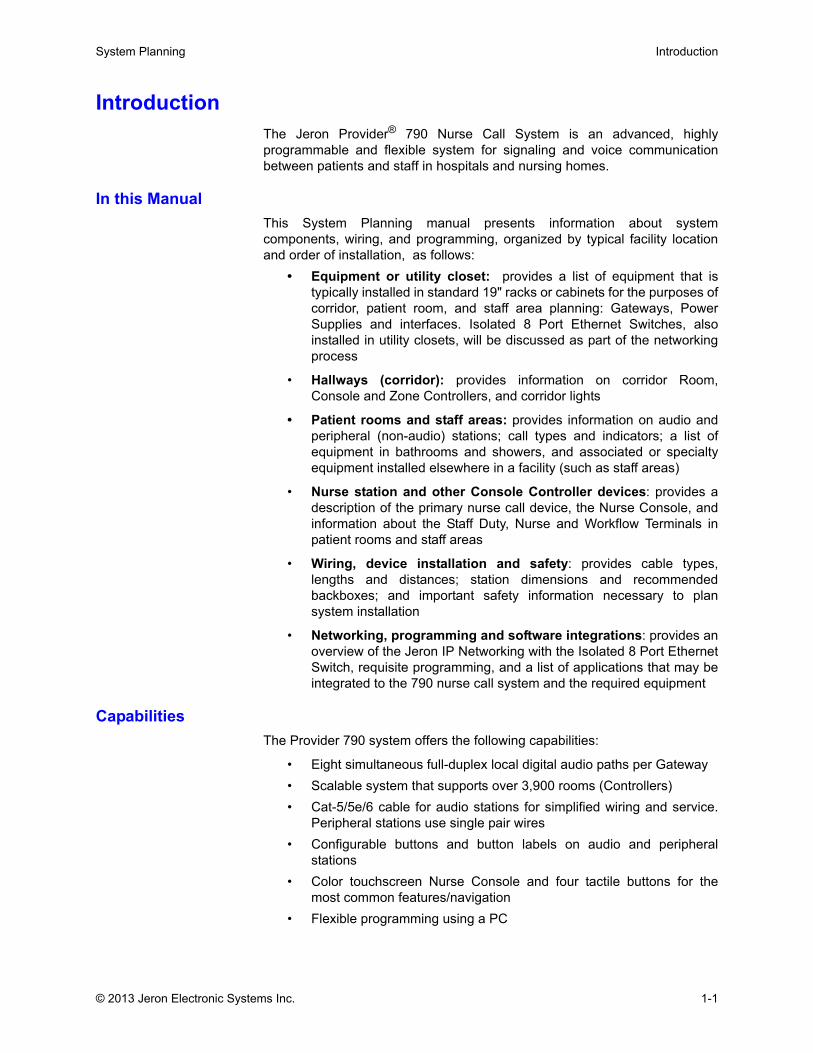
IntroductionThe Jeron Provider® 790 Nurse Call System is an advanced, highlyprogrammable and flexible system for signaling and voice communicationbetween patients and staff in hospitals and nursing homes.
In this ManualThis System Planning manual presents information about systemcomponents, wiring, and programming, organized by typical facility locationand order of installation, as follows:
• Equipment or utility closet: provides a list of equipment that istypically installed in standard 19" racks or cabinets for the purposes ofcorridor, patient room, and staff area planning: Gateways, PowerSupplies and interfaces. Isolated 8 Port Ethernet Switches, alsoinstalled in utility closets, will be discussed as part of the networkingprocess
• Hallways (corridor): provides information on corridor Room,Console and Zone Controllers, and corridor lights
• Patient rooms and staff areas: provides information on audio andperipheral (non-audio) stations; call types and indicators; a list ofequipment in bathrooms and showers, and associated or specialtyequipment installed elsewhere in a facility (such as staff areas)
• Nurse station and other Console Controller devices: provides adescription of the primary nurse call device, the Nurse Console, andinformation about the Staff Duty, Nurse and Workflow Terminals inpatient rooms and staff areas
• Wiring, device installation and safety: provides cable types,lengths and distances; station dimensions and recommendedbackboxes; and important safety information necessary to plansystem installation
• Networking, programming and software integrations: provides anoverview of the Jeron IP Networking with the Isolated 8 Port EthernetSwitch, requisite programming, and a list of applications that may beintegrated to the 790 nurse call system and the required equipment
CapabilitiesThe Provider 790 system offers the following capabilities:
• Eight simultaneous full-duplex local digital audio paths per Gateway• Scalable system that supports over 3,900 rooms (Controllers)• Cat-5/5e/6 cable for audio stations for simplified wiring and service.
Peripheral stations use single pair wires • Configurable buttons and button labels on audio and peripheral
stations• Color touchscreen Nurse Console and four tactile buttons for the
most common features/navigation• Flexible programming using a PC
© 2013 Jeron Electronic Systems Inc. 1-1
Introduction System Planning
Jeron IP Network & Facility LANThe backbone of the Provider system is the Jeron IP Network. The networkednurse call architecture supports flexible room coverage and call routingthroughout the entire facility. Optional integrations provide added functionalityto staff members, including EIS report generation or real-time display ofsystem call activity on client PCs on the facility LAN. The system can alsointerface with popular third-party devices and equipment, including:
• Admission-Discharge-Transfer (ADT) application to map HL7 fields toProvider 790 for display on consoles or terminals
• RTLS badges for automatic registration of staff in and out of rooms• Wireless SIP handsets for direct call routing of patient calls to
assigned caregiver• Pocket pagers for staff member notification of patient calls
Refer to See “Optional Software Integrations” on page 8-12 for a complete listof available applications.
1-2 © 2013 Jeron Electronic Systems Inc.
System Planning System Architecture
System ArchitectureOverview
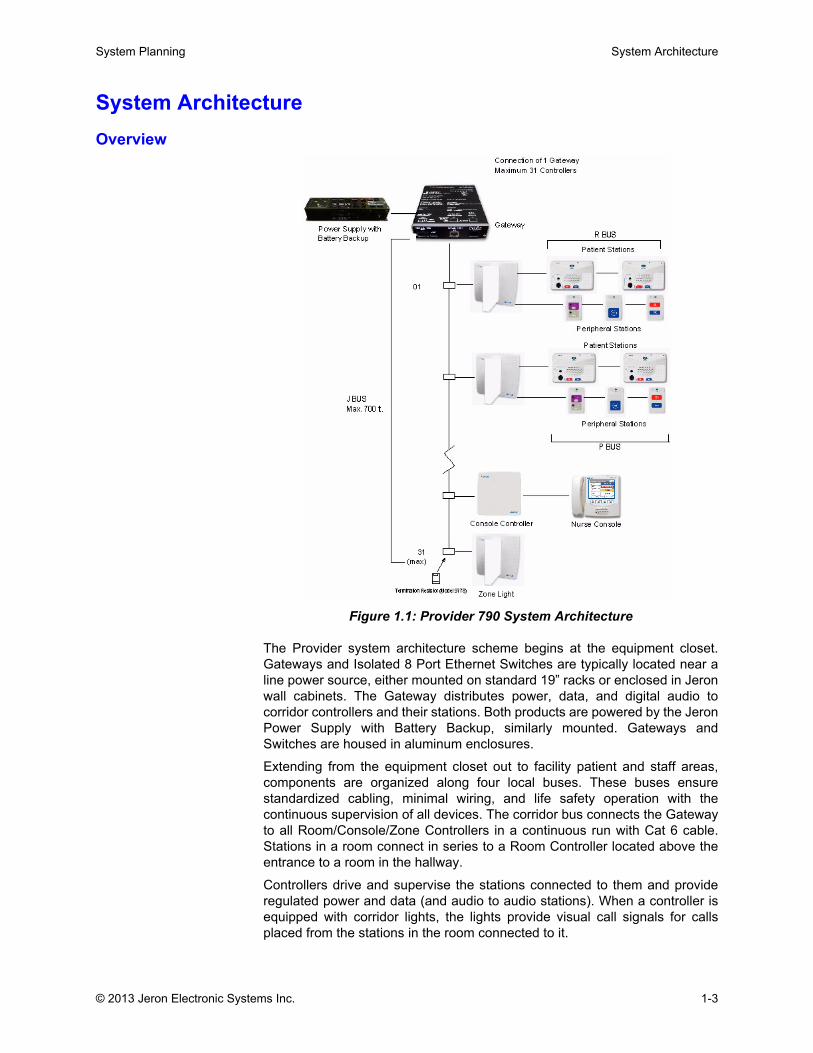
Figure 1.1: Provider 790 System Architecture
The Provider system architecture scheme begins at the equipment closet.Gateways and Isolated 8 Port Ethernet Switches are typically located near aline power source, either mounted on standard 19” racks or enclosed in Jeronwall cabinets. The Gateway distributes power, data, and digital audio tocorridor controllers and their stations. Both products are powered by the JeronPower Supply with Battery Backup, similarly mounted. Gateways andSwitches are housed in aluminum enclosures.
Extending from the equipment closet out to facility patient and staff areas,components are organized along four local buses. These buses ensurestandardized cabling, minimal wiring, and life safety operation with thecontinuous supervision of all devices. The corridor bus connects the Gatewayto all Room/Console/Zone Controllers in a continuous run with Cat 6 cable.Stations in a room connect in series to a Room Controller located above theentrance to a room in the hallway.
Controllers drive and supervise the stations connected to them and provideregulated power and data (and audio to audio stations). When a controller isequipped with corridor lights, the lights provide visual call signals for callsplaced from the stations in the room connected to it.
© 2013 Jeron Electronic Systems Inc. 1-3
System Architecture System Planning
Audio stations connect via Cat 5/5e/6 cable. Peripheral stations connect inseries to a Room Controller via 22 AWG wire pair.
Zone Controllers with dome lights are located in those portions of a corridorwhere room dome lights may not be visible to the nurse station.
A Nurse Console, Staff Duty Terminal, Workflow Terminal, or Nurse Terminalconnects to a Console Controller and serve as main hubs for nurse callactivity management for attendants.
Jeron Nurse Call BusesThe Provider system uses four local buses:
J Bus
• CAT 6 Cable (23 AWG)• Corridor runs – connects Gateway to: Room, Console and Zone
Controllers• Refer to “Hallway J Bus Devices” on page 3-1
R Bus
• CAT 5 or better Cable• Connects all audio stations with Room Controllers• Refer to “Audio R Bus Stations” on page 4-3
P Bus
• Single 22 AWG unshielded, twisted pair (UTP)• Connects all non-audio (peripheral) stations with Room Controllers• Refer to “Peripheral P Bus Stations” on page 4-17
M Bus
• CAT 6 or better Cable• Connects a Nurse Console or Staff Duty, Workflow, or Nurse
Terminal to a Console Controller • Refer to “Call Center M Bus Stations” on page 5-1
System CapacityRefer to the information below to determine the number of Gateways andNurse Call Isolated 8 Port Ethernet Switches required.
Each Gateway is assigned a unique IP address and location name prior toconnection. IP addresses must start with x.x.x.1 for the first Gateway and becontinuously sequential for all subsequent Gateways.
More than one Gateway in a system require a Nurse Call Isolated 8 PortEthernet Switch.
1-4 © 2013 Jeron Electronic Systems Inc.
System Planning System Types
Single Gateway J BusA combination of up to 31 Controllers (Room, Console, Zone) per Gateway isallowed.
Maximum distance between Gateway to last controller: 700 ft.
Supports up to eight (8) simultaneous full duplex audio paths.
Maximum GatewaysA maximum of 127 Gateways are supported by the system for a combinationof over 3900 controllers.
Single Nurse Call Isolated 8 Port Ethernet SwitchA maximum of eight (8) Gateways connect to one (1) Isolated Switch for atotal of 248 rooms.
Multiple Nurse Call Isolated 8 Port Ethernet SwitchOne system can accept a maximum of 16 Isolated Switches for Gateways,with an additional three (3) for Switch-to-Switch use. Up to eight (8) Switchesare permitted between any two (2) Gateways.
Room ControllersCombined total of 15 R Bus and P Bus stations allowed on one (1) RoomController.
Console (Master) Controller One Nurse Console, Staff Duty Terminal, Workflow Terminal or NurseTerminal station allowed per controller.
Note: Console Controllers supporting Nurse Consoles, Staff Duty Terminalsor Nurse Terminals should be limited to four (4) per Gateway when possible toensure non-blocking audio connections.
Power Supply
One Power Supply per Gateway at a minimum. Add one per each Switch thatis NOT located next to a Gateway. One additional Power Supply is necessaryto support between three (3) and eight (8) supplemental Console Controllerson a single Gateway; two (2) additional Power Supplies needed for nine (9) to15 supplemental Console Controllers on a single Gateway.
System TypesAudio Visual
Typically installed in long term care facilities and hospitals, the audio-visualsystem provides full duplex two-way voice communication between patientand staff. The calling station, equipped with a microphone and speaker,allows the patient to place a call to the Nurse Console and communicate withthe nurse via a pillow speaker. Depending on call type, the call may becanceled at the console or at the originating station.
© 2013 Jeron Electronic Systems Inc. 1-5
Getting Started System Planning
Audio Visual with IntegrationsTypically installed in hospitals, the audio-visual system with integrationsintegrates the Jeron system with Jeron applications and third-partyequipment, such as: client PCs to mirror nurse call activity on the system;wireless handsets and pocket pagers to be able to send calls directly to thedevices carried by staff; Executive Information System to create nurse callactivity reports; ADT integration to interface the Jeron nurse call system withthe facility’s Admissions, Discharge and Transfer (ADT) HL7-compliantapplication to automatically transmit relevant patient information; and IRLocator to locate staff members easily.
Tone VisualTypically installed in assisted living facilities, in the tone visual system calldevices generate tones, light dome/zone lights in hallways and annunciate atthe nurse console. No voice communication is established between patientand staff. Calls are canceled at the station that originated the call.
Getting StartedWhile standard practices are established for both the physical locations andelectrical connections of the system components, compliance with any localor state regulations that may apply to that specific application is also required.
System layouts and installation procedures should be completed anddiscussed with the customer well in advance of the arrival of the equipment atthe site. Failure to do so may result in system installation delays.
Follow the steps below when conducting system planning:
• Understand 790 cable requirements/limits and equipment featurecapabilities as discussed herein
• Obtain specifications, architectural/electrical drawings and/or conductwalk-thru of jobsite.
• Compile a room-by-room material list that groups required equipmentby nursing unit and floor
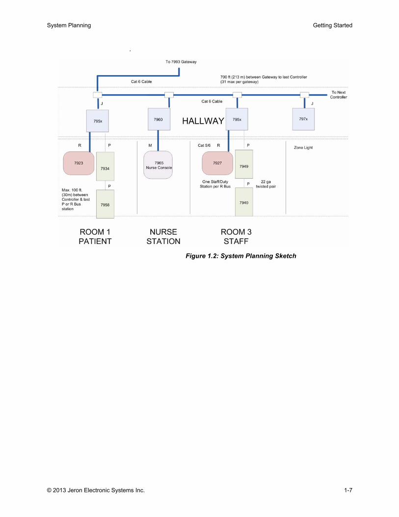
• Make a single sketch showing each corridor J Bus cable run withRoom, Console, and Zone Controller locations and identity. Expandthis drawing with R Bus and P Bus stations for each room, accordingto specifications provided in this manual. Refer to Figure 1.2 for anexample
1-6 © 2013 Jeron Electronic Systems Inc.
System Planning Getting Started
.
Figure 1.2: System Planning Sketch
© 2013 Jeron Electronic Systems Inc. 1-7

Getting Started System Planning
1-8 © 2013 Jeron Electronic Systems Inc.

Chapter 2: Equipment Closet
.
.

System Planning Overview
Overview
Figure 2.1: Equipment Closet
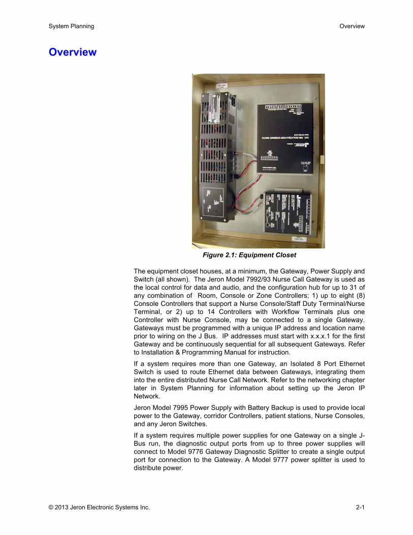
The equipment closet houses, at a minimum, the Gateway, Power Supply andSwitch (all shown). The Jeron Model 7992/93 Nurse Call Gateway is used asthe local control for data and audio, and the configuration hub for up to 31 ofany combination of Room, Console or Zone Controllers; 1) up to eight (8)Console Controllers that support a Nurse Console/Staff Duty Terminal/NurseTerminal, or 2) up to 14 Controllers with Workflow Terminals plus oneController with Nurse Console, may be connected to a single Gateway.Gateways must be programmed with a unique IP address and location nameprior to wiring on the J Bus. IP addresses must start with x.x.x.1 for the firstGateway and be continuously sequential for all subsequent Gateways. Referto Installation & Programming Manual for instruction.
If a system requires more than one Gateway, an Isolated 8 Port EthernetSwitch is used to route Ethernet data between Gateways, integrating theminto the entire distributed Nurse Call Network. Refer to the networking chapterlater in System Planning for information about setting up the Jeron IPNetwork.
Jeron Model 7995 Power Supply with Battery Backup is used to provide localpower to the Gateway, corridor Controllers, patient stations, Nurse Consoles,and any Jeron Switches.
If a system requires multiple power supplies for one Gateway on a single J-Bus run, the diagnostic output ports from up to three power supplies willconnect to Model 9776 Gateway Diagnostic Splitter to create a single outputport for connection to the Gateway. A Model 9777 power splitter is used todistribute power.
© 2013 Jeron Electronic Systems Inc. 2-1
Gateways System Planning
This chapter provides detailed information about these components, whichare typically located in utility rooms, and an explanation of powerrequirements.
GatewaysModel 7992/93 Nurse Call Gateway
Each Gateway is an IP device that acts as the central transition point, or“gateway”, between the Jeron IP network and the proprietary RS-485 corridornetwork with attached patient stations or nurse consoles.
Up to 31 Room/Console/Zone Controllers connect on the J Bus on acontinuous run to a Gateway via 9779 splitters and a Cat-6 cable (23 AWG).Maximum distance is 700 ft. The Gateway connects corridor controllers andstations to the Jeron IP Network via industry standard Cat-6/5e cable withRJ45 connectors.
During the hardware installation process, the Gateway automatically learnsand saves, in non-volatile memory, the model and identity of each stationattached to the corridor network. The 7993 Gateway acquires an IP addressfrom the 7990 Administration Program Software on the PC (refer tonetworking chapter), which then downloads and configure the data stored inthe Gateway to associate it with hospital nursing units.
The Gateway continuously supervises all local devices (Nurse Consoles, StaffDuty or Nurse Terminals, zone lights, Room Controllers, patient stations,pullcord stations, etc.) to ensure every component of the system isoperational. If a local device fails, an alert is sent to designated NurseConsole(s), terminal(s), and optionally, to pocket pager(s) carried by supportstaff.
A Gateway would be utilized on a single floor and may cover all or some ofthe rooms in a certain unit (floor). One Gateway may be sufficient for multipleunits on a floor if the units do not exceed the 31 room limit. A unit may requiremore than one Gateway if the unit exceeds the number of rooms supported bya Gateway (max 31) or the length of the J Bus exceeds 700 feet.
Gateways should be located in a secure area and are mounted in a standard19” equipment rack using a Jeron Model 9840 adaptor or a 7988/89 wallcabinet. If connected to a Nurse Call Isolated 8 Port Ethernet Switch,maximum distance from Gateway to switch should not exceed 328 ft. (100 m).Refer to page 7-1.
2-2 © 2013 Jeron Electronic Systems Inc.
System Planning Gateways
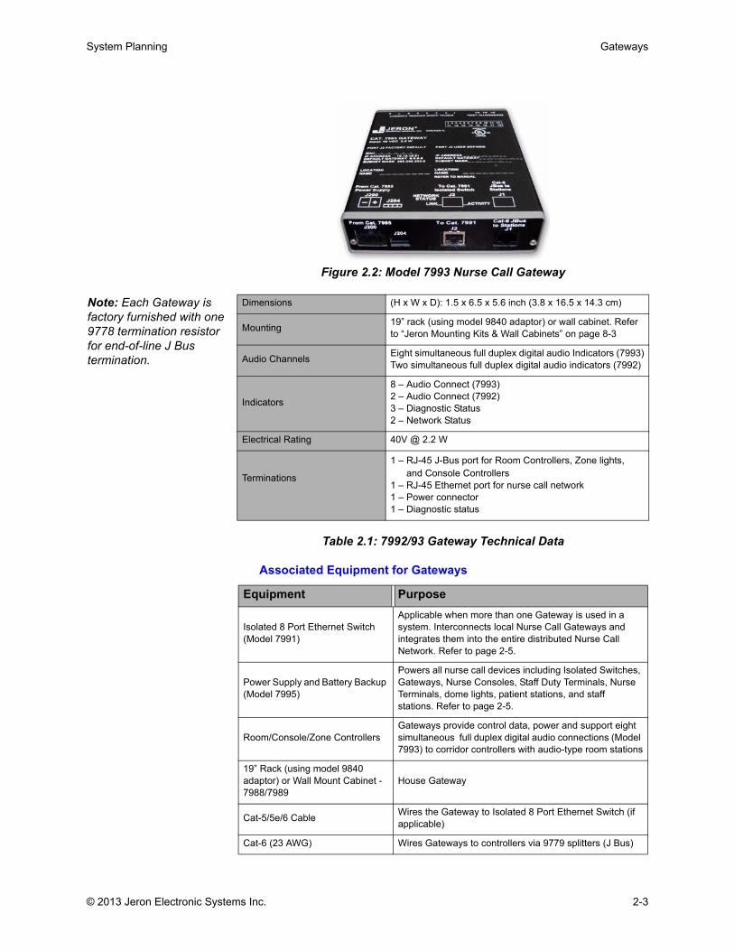
Figure 2.2: Model 7993 Nurse Call Gateway
Table 2.1: 7992/93 Gateway Technical Data
Associated Equipment for Gateways
Dimensions (H x W x D): 1.5 x 6.5 x 5.6 inch (3.8 x 16.5 x 14.3 cm)
Mounting 19” rack (using model 9840 adaptor) or wall cabinet. Refer to “Jeron Mounting Kits & Wall Cabinets” on page 8-3
Audio Channels Eight simultaneous full duplex digital audio Indicators (7993)Two simultaneous full duplex digital audio indicators (7992)
Indicators
8 – Audio Connect (7993)2 – Audio Connect (7992)3 – Diagnostic Status2 – Network Status
Electrical Rating 40V @ 2.2 W
Terminations
1 – RJ-45 J-Bus port for Room Controllers, Zone lights, and Console Controllers1 – RJ-45 Ethernet port for nurse call network1 – Power connector1 – Diagnostic status
Equipment Purpose
Isolated 8 Port Ethernet Switch (Model 7991)
Applicable when more than one Gateway is used in a system. Interconnects local Nurse Call Gateways and integrates them into the entire distributed Nurse Call Network. Refer to page 2-5.
Power Supply and Battery Backup (Model 7995)
Powers all nurse call devices including Isolated Switches, Gateways, Nurse Consoles, Staff Duty Terminals, Nurse Terminals, dome lights, patient stations, and staff stations. Refer to page 2-5.
Room/Console/Zone ControllersGateways provide control data, power and support eight simultaneous full duplex digital audio connections (Model 7993) to corridor controllers with audio-type room stations
19” Rack (using model 9840 adaptor) or Wall Mount Cabinet - 7988/7989
House Gateway
Cat-5/5e/6 Cable Wires the Gateway to Isolated 8 Port Ethernet Switch (if applicable)
Cat-6 (23 AWG) Wires Gateways to controllers via 9779 splitters (J Bus)
Note: Each Gateway is factory furnished with one 9778 termination resistor for end-of-line J Bus termination.
© 2013 Jeron Electronic Systems Inc. 2-3

Gateways System Planning
Table 2.2: Associated Equipment for Gateways
2-4 © 2013 Jeron Electronic Systems Inc.

System Planning Power Supply
Power SupplyModel 7995 Power Supply with Battery Backup
Powers all nurse call devices including Isolated 8 Port Ethernet Switches,Gateways, touchscreen Nurse Consoles, terminals, dome lights, patientstations, and staff stations.
The number of Power Supplies required depends on the types of devices andstations used on the system and the total size of the system.
Typically, the power supply is rack mounted on 19” rack or wall mounted on7988/7989 Wall Mount Cabinet within 24 inches of the Gateway.
Figure 2.3: Model 7995 Power Supply with Battery Backup
Table 2.3: 7995 Technical Data
Required Equipment for Power Supply with Battery Backup
Table 2.4: 7995 Associated Equipment
Dimensions (H x W x D): 4 x 19 x 3.6 inch (10 x 48 x 9 cm)
Enclosure Metal, black finish
Mounting 19” mounting rack or Model 7988/7989 Wall Cabinet
Connectors and Switches
1 – Fused AC receptacle1 – Remote diagnostics plug1 – Main DC power output3 – Auxiliary DC Power outputs1 – Power switch1 – Earth ground lug
Diagnostics LEDs
1 – Ground fault (yellow)1 – DC Status (green)1 – Battery charge (yellow)1 – AC status (green)
Input 120 VAC, 60Hz, 2A
Output 40 VDC @ 100 VA
Battery Backup Fully charged battery will provide full system operation for a minimum four minutes.
Equipment PurposeWall Mount Cabinet - 7988/7989 or 19” Rack mounted Houses power supply unit
Two factory furnished 30 inch cables Wire to Gateway
Two conductor 18 or 16 AWG wires Wire to Isolated 8 Port Ethernet Switch
Gateway Provide power to Gateway and its connected devices
Isolated 8 Port Ethernet Switch Provides power to Isolated 8 Port Ethernet Switch
© 2013 Jeron Electronic Systems Inc. 2-5

Connecting Gateway & Power Supply System Planning
Connecting Gateway & Power Supply Together with the 7995 Power Supply and Battery Backup, the Gatewayprovides control data, power and supports eight simultaneous full duplexdigital audio connections (Model 7993) to corridor Controllers with audio-typeroom stations.
Figure 2.4: Wiring Power Supply to Gateway
Power Supply Requirements Per GatewayBy Number of J Bus Devices (Prism Dome Lights)
Table 2.5: Power Supply Requirements on J Bus w/ Dome Lights
For 7967-P Terminal Intercom Operation Only (No Dome Lights)
Gateway Model 7993
To Switch
Max 31 Room/Master Controllers per Gateway. Maximum 700 ft. J Bus.
CAT-5/6
CAT-6
120 VAC Line
Factory furnished 30 in. cable
Factory furnished 30 in. cable
Power Supply
JBus
Jeron Network Port
To Room/Master
Controllers via
9779 Splitter
_ + _ +
Model 7995
J2 J1
J200
J204 S1
J100
J200
J204
7991
Power to Switch(as required)
J Bus Devices w/ Prism Dome
Light
7965 Console/7967 Terminal
7995 Power Supply
9777 Supplemental
Power Wire (see page 2-8)
9776 Diagnostic Splitter (see
below)
up to 20 up to 2 1 0 0up to 31 up to 2 1 1 (Loop or Split) 0up to 31 up to 4 2 1 (Loop or Split) 1up to 31 up to 16 3 2 (Loop or Split) 1
One 9777 Power Splitter required for each 7995 Power Supply with more than 20 J Bus devices. One 9776 Diagnostic Splitter required if there are more 7995 Power Supplies than 7993 Gateways. One 9776 required for up to three 7995 on same 7993 J Bus.
Console Controllers (on a
single J Bus)
# of 7967-P Workflow Terminal
7995 9777 9776
up to 8 up to 8 2 1 (Loop or Split) 1
up to 15 up to 15 3 2 (Loop or Split) 1
Table 2.6: Power Supply Requirement for Workflow Terminals
2-6 © 2013 Jeron Electronic Systems Inc.
System Planning Connecting Gateway & Power Supply
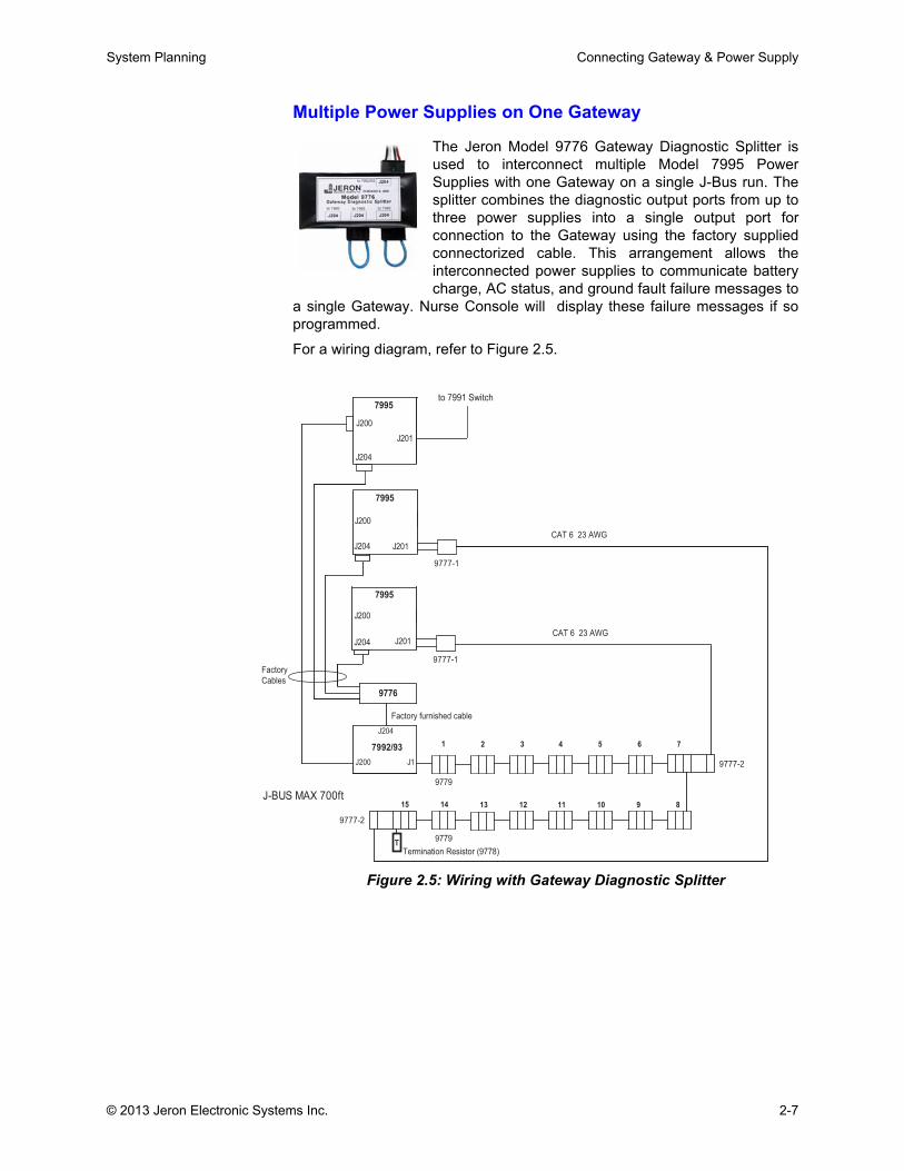
Multiple Power Supplies on One Gateway
The Jeron Model 9776 Gateway Diagnostic Splitter isused to interconnect multiple Model 7995 PowerSupplies with one Gateway on a single J-Bus run. Thesplitter combines the diagnostic output ports from up tothree power supplies into a single output port forconnection to the Gateway using the factory suppliedconnectorized cable. This arrangement allows theinterconnected power supplies to communicate batterycharge, AC status, and ground fault failure messages to
a single Gateway. Nurse Console will display these failure messages if soprogrammed.
For a wiring diagram, refer to Figure 2.5.
Figure 2.5: Wiring with Gateway Diagnostic Splitter
9777-1
J200
7995
J201
J200
7995
J201
J200
7995
J1J200
7992/93
9776
J204
J201
to 7991 Switch
J204
J204
J204
9777-1
9777-2
9779
9779T
9777-2
1 2 3 4 5 6 7
14 13 12 11 10 9 815
Factory
Cables
Factory furnished cable
J-BUS MAX 700ft
Termination Resistor (9778)
CAT 6 23 AWG
CAT 6 23 AWG
© 2013 Jeron Electronic Systems Inc. 2-7
Connecting Gateway & Power Supply System Planning
Figure 2.5 displays a single J Bus run of 15 locations (see Table 2.7) with themaximum of 31 Controllers on one Gateway, using three 7995 PowerSupplies, two 9777 Power Splitters and a 9776 Gateway Diagnostic Splitter.
Table 2.7: Capacity for One Gateway with Multiple Power Supplies
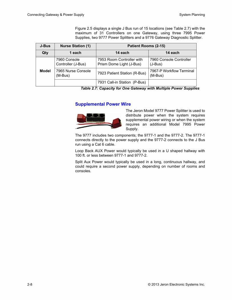
Supplemental Power WireThe Jeron Model 9777 Power Splitter is used todistribute power when the system requiressupplemental power wiring or when the systemrequires an additional Model 7995 PowerSupply.
The 9777 includes two components; the 9777-1 and the 9777-2. The 9777-1connects directly to the power supply and the 9777-2 connects to the J Busrun using a Cat 6 cable.
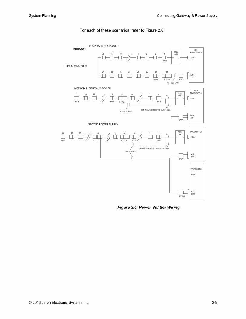
Loop Back AUX Power would typically be used in a U shaped hallway with100 ft. or less between 9777-1 and 9777-2.
Split Aux Power would typically be used in a long, continuous hallway, andcould require a second power supply, depending on number of rooms andconsoles.
J-Bus Nurse Station (1) Patient Rooms (2-15)
Qty 1 each 14 each 14 each
Model
7960 Console Controller (J-Bus)
7953 Room Controller with Prism Dome Light (J-Bus)
7960 Console Controller (J-Bus)
7965 Nurse Console (M-Bus) 7923 Patient Station (R-Bus) 7967-P Workflow Terminal
(M-Bus)
7931 Call-in Station (P-Bus)
2-8 © 2013 Jeron Electronic Systems Inc.
System Planning Connecting Gateway & Power Supply
For each of these scenarios, refer to Figure 2.6.
Figure 2.6: Power Splitter Wiring
9777-1
J200
22
5
221
29 6
9779
J5
POWER SUPPLY
7992
J201
J-BUS MAX 700ft
4
25
9777-2
1
24
J5
26
2
7992
J201
AUX
3
9777-1
RUN IN SAME CONDUIT AS CAT-6 J-BUS
9779
1
7993
9779
J1
15
RUN IN SAME CONDUIT AS CAT-6 J-BUS
7995
J1
14
7995
9779
31
J201
1
27 28
POWER SUPPLY29
SPLIT AUX POWER
29
7993
AUX
7992
16
AUX
SECOND POWER SUPPLY
AUX
2
J200
9779
9779
POWER SUPPLY
9777-2
9779
30
J201
J1
16
J200
POWER SUPPLY
METHOD 2
30
9777-2
J200
METHOD 1
7
J5
9777-1
LOOP BACK AUX POWER
31
9777-2
30
31
23
9779
9777-1
7993
CAT-6 23 AWG
CAT-6 23 AWG
CAT-6 23 AWG
© 2013 Jeron Electronic Systems Inc. 2-9

Connecting Gateway & Power Supply System Planning
2-10 © 2013 Jeron Electronic Systems Inc.

Chapter 3: Hallways

.
System Planning Hallway J Bus Devices
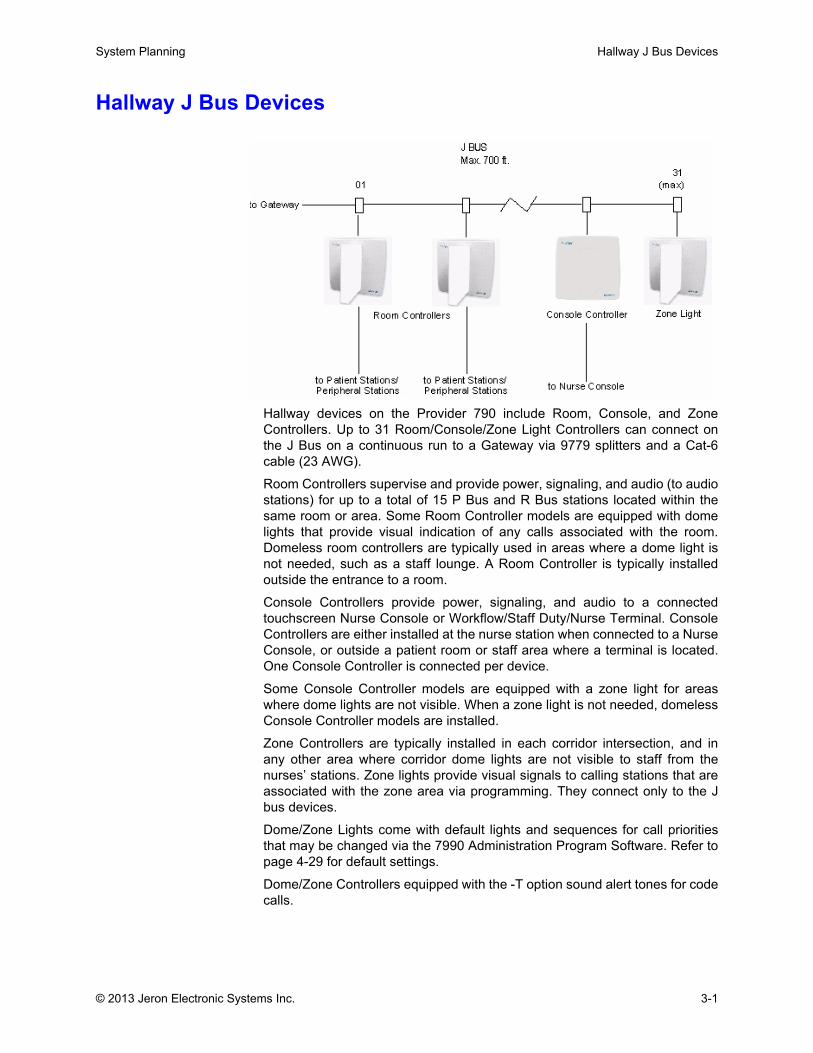
Hallway J Bus Devices
Hallway devices on the Provider 790 include Room, Console, and ZoneControllers. Up to 31 Room/Console/Zone Light Controllers can connect onthe J Bus on a continuous run to a Gateway via 9779 splitters and a Cat-6cable (23 AWG).
Room Controllers supervise and provide power, signaling, and audio (to audiostations) for up to a total of 15 P Bus and R Bus stations located within thesame room or area. Some Room Controller models are equipped with domelights that provide visual indication of any calls associated with the room.Domeless room controllers are typically used in areas where a dome light isnot needed, such as a staff lounge. A Room Controller is typically installedoutside the entrance to a room.
Console Controllers provide power, signaling, and audio to a connectedtouchscreen Nurse Console or Workflow/Staff Duty/Nurse Terminal. ConsoleControllers are either installed at the nurse station when connected to a NurseConsole, or outside a patient room or staff area where a terminal is located.One Console Controller is connected per device.
Some Console Controller models are equipped with a zone light for areaswhere dome lights are not visible. When a zone light is not needed, domelessConsole Controller models are installed.
Zone Controllers are typically installed in each corridor intersection, and inany other area where corridor dome lights are not visible to staff from thenurses’ stations. Zone lights provide visual signals to calling stations that areassociated with the zone area via programming. They connect only to the Jbus devices.
Dome/Zone Lights come with default lights and sequences for call prioritiesthat may be changed via the 7990 Administration Program Software. Refer topage 4-29 for default settings.
Dome/Zone Controllers equipped with the -T option sound alert tones for codecalls.
© 2013 Jeron Electronic Systems Inc. 3-1
Hallway J Bus Devices System Planning
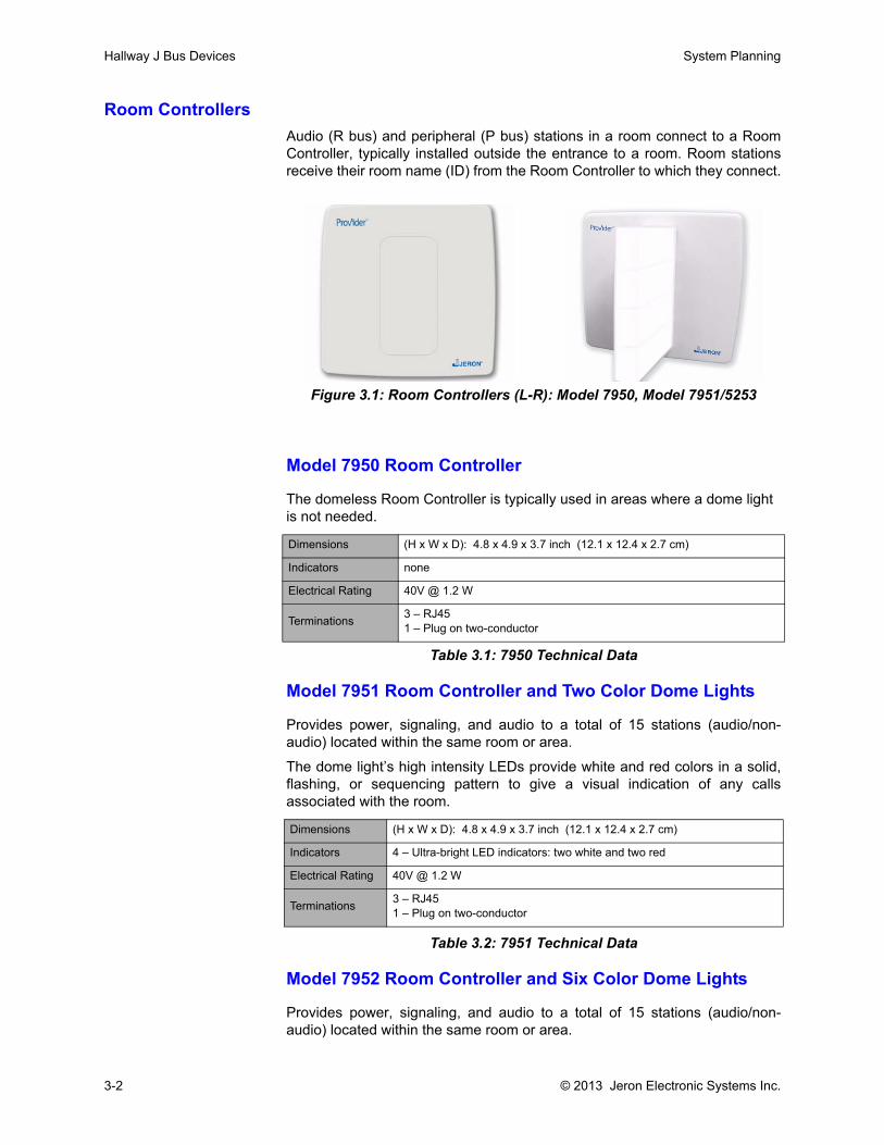
Room ControllersAudio (R bus) and peripheral (P bus) stations in a room connect to a RoomController, typically installed outside the entrance to a room. Room stationsreceive their room name (ID) from the Room Controller to which they connect.
Figure 3.1: Room Controllers (L-R): Model 7950, Model 7951/5253
Model 7950 Room Controller
The domeless Room Controller is typically used in areas where a dome light is not needed.
Model 7951 Room Controller and Two Color Dome Lights
Provides power, signaling, and audio to a total of 15 stations (audio/non-audio) located within the same room or area.
The dome light’s high intensity LEDs provide white and red colors in a solid,flashing, or sequencing pattern to give a visual indication of any callsassociated with the room.
Table 3.2: 7951 Technical Data
Model 7952 Room Controller and Six Color Dome Lights
Provides power, signaling, and audio to a total of 15 stations (audio/non-audio) located within the same room or area.
Dimensions (H x W x D): 4.8 x 4.9 x 3.7 inch (12.1 x 12.4 x 2.7 cm)
Indicators none
Electrical Rating 40V @ 1.2 W
Terminations 3 – RJ451 – Plug on two-conductor
Table 3.1: 7950 Technical Data
Dimensions (H x W x D): 4.8 x 4.9 x 3.7 inch (12.1 x 12.4 x 2.7 cm)
Indicators 4 – Ultra-bright LED indicators: two white and two red
Electrical Rating 40V @ 1.2 W
Terminations 3 – RJ451 – Plug on two-conductor
3-2 © 2013 Jeron Electronic Systems Inc.
System Planning Hallway J Bus Devices
The dome light’s high intensity LEDs provide up to six distinct colors in a solid,flashing, or sequencing pattern to give a visual indication of any calls, up tofour unique levels of service requirements, or up to three unique levels of staffpresence associated with the room. The flexibility of the dome light allows it tosimultaneously indicate both the highest call priority in the room plus either anactive service requirement set for the room or the highest level of staff presentin the room.
Table 3.3: 7952 Technical Data
Model 7953 Room Controller and Prism Dome LightProvides power, signaling, and audio to a total of 15 stations (audio/non-audio) located within the same room or area.
The Prism dome light functionality gives a visual indication of any calls, up tofour unique levels of service requirements, or up to three unique levels of staffpresence associated with the room. Prism is recommended when needing therange of visual signals necessary for notification of room status events (e.g.,rounding, housekeeping, and patient fall notification).
Table 3.4: 7953 Technical Data
Dimensions (H x W x D): 4.8 x 4.9 x 3.7 inch (12.1 x 12.4 x 2.7 cm)
Indicators 6 – Ultra-bright LED indicators: white, red, blue, orange, green, and yellow
Electrical Rating 40V @ 1.2 W
Terminations 3 – RJ451 – Plug on two-conductor
Dimensions (H x W x D): 4.8 x 4.9 x 3.7 inch (12.1 x 12.4 x 2.7 cm)
Indicators8 – Ultra-bright LED indicators: two per Dome Light segment, capable of producing up to eight distinct colors (white, red, yellow, orange, green, blue, magenta, and pink)
Electrical Rating 40V @ 1.2 W
Terminations 3 – RJ451 – Plug on two-conductor
© 2013 Jeron Electronic Systems Inc. 3-3
Hallway J Bus Devices System Planning
Associated Equipment for Room Controllers
Table 3.5: Room Controllers Associated Equipment
Equipment Purpose
Back boxTo mount the dome light use two-gang backbox with a two-gang trim ring. Refer to “Backboxes, Mounting Racks & Wall Cabinets” on page 8-1
Factory furnished Cable
To connect Room Controller to Gateway/other devices on the J Bus in series via 9779 Splitter. Each Gateway supports up to 31 rooms (combination of Room/Console/Zone Controllers)
Cat-6 Cable To connect 9779 splitters in series on the J Bus in a continuous run
Cat-5 (minimum) Cable To connect to R Bus stations (audio)
Pair of 22 AWG wires To connect to P Bus stations (peripheral)
R Bus Stations Connect to Controller
P Bus Stations Connect to Controller
Gateway Supports up 31 Room Controllers
3-4 © 2013 Jeron Electronic Systems Inc.
System Planning Hallway J Bus Devices
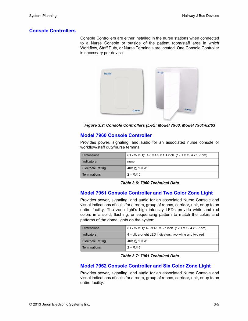
Console ControllersConsole Controllers are either installed in the nurse stations when connectedto a Nurse Console or outside of the patient room/staff area in whichWorkflow, Staff Duty, or Nurse Terminals are located. One Console Controlleris necessary per device.
Figure 3.2: Console Controllers (L-R): Model 7960, Model 7961/62/63
Model 7960 Console ControllerProvides power, signaling, and audio for an associated nurse console orworkflow/staff duty/nurse terminal.
Table 3.6: 7960 Technical Data
Model 7961 Console Controller and Two Color Zone LightProvides power, signaling, and audio for an associated Nurse Console andvisual indications of calls for a room, group of rooms, corridor, unit, or up to anentire facility. The zone light’s high intensity LEDs provide white and redcolors in a solid, flashing, or sequencing pattern to match the colors andpatterns of the dome lights on the system.
Table 3.7: 7961 Technical Data
Model 7962 Console Controller and Six Color Zone LightProvides power, signaling, and audio for an associated Nurse Console andvisual indications of calls for a room, group of rooms, corridor, unit, or up to anentire facility.
Dimensions (H x W x D): 4.8 x 4.9 x 1.1 inch (12.1 x 12.4 x 2.7 cm)
Indicators none
Electrical Rating 40V @ 1.0 W
Terminations 2 – RJ45
Dimensions (H x W x D): 4.8 x 4.9 x 3.7 inch (12.1 x 12.4 x 2.7 cm)
Indicators 4 – Ultra-bright LED indicators: two white and two red
Electrical Rating 40V @ 1.0 W
Terminations 2 – RJ45
© 2013 Jeron Electronic Systems Inc. 3-5
Hallway J Bus Devices System Planning
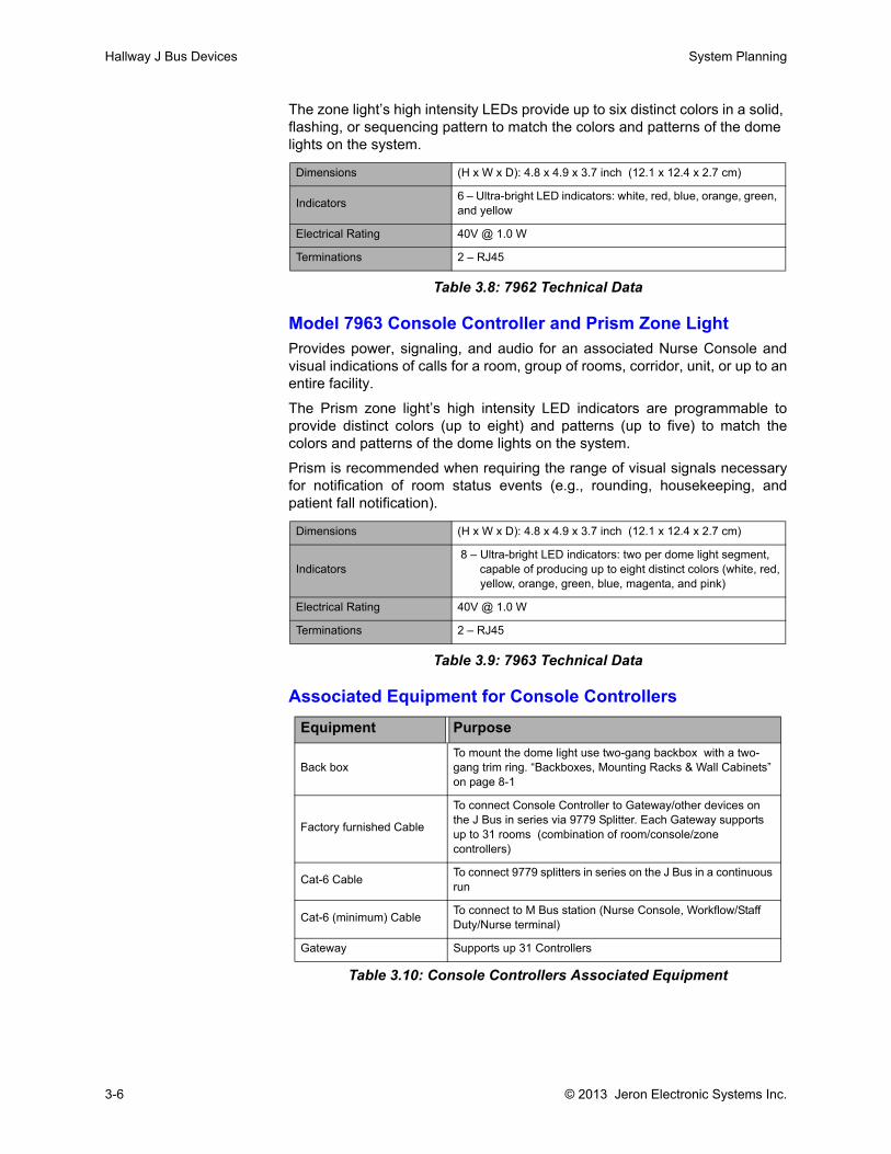
The zone light’s high intensity LEDs provide up to six distinct colors in a solid, flashing, or sequencing pattern to match the colors and patterns of the dome lights on the system.
Table 3.8: 7962 Technical Data
Model 7963 Console Controller and Prism Zone LightProvides power, signaling, and audio for an associated Nurse Console andvisual indications of calls for a room, group of rooms, corridor, unit, or up to anentire facility.
The Prism zone light’s high intensity LED indicators are programmable toprovide distinct colors (up to eight) and patterns (up to five) to match thecolors and patterns of the dome lights on the system.
Prism is recommended when requiring the range of visual signals necessaryfor notification of room status events (e.g., rounding, housekeeping, andpatient fall notification).
Table 3.9: 7963 Technical Data
Associated Equipment for Console Controllers
Table 3.10: Console Controllers Associated Equipment
Dimensions (H x W x D): 4.8 x 4.9 x 3.7 inch (12.1 x 12.4 x 2.7 cm)
Indicators 6 – Ultra-bright LED indicators: white, red, blue, orange, green, and yellow
Electrical Rating 40V @ 1.0 W
Terminations 2 – RJ45
Dimensions (H x W x D): 4.8 x 4.9 x 3.7 inch (12.1 x 12.4 x 2.7 cm)
Indicators 8 – Ultra-bright LED indicators: two per dome light segment, capable of producing up to eight distinct colors (white, red, yellow, orange, green, blue, magenta, and pink)
Electrical Rating 40V @ 1.0 W
Terminations 2 – RJ45
Equipment Purpose
Back boxTo mount the dome light use two-gang backbox with a two-gang trim ring. “Backboxes, Mounting Racks & Wall Cabinets” on page 8-1
Factory furnished Cable
To connect Console Controller to Gateway/other devices on the J Bus in series via 9779 Splitter. Each Gateway supports up to 31 rooms (combination of room/console/zone controllers)
Cat-6 Cable To connect 9779 splitters in series on the J Bus in a continuous run
Cat-6 (minimum) Cable To connect to M Bus station (Nurse Console, Workflow/Staff Duty/Nurse terminal)
Gateway Supports up 31 Controllers
3-6 © 2013 Jeron Electronic Systems Inc.
System Planning Hallway J Bus Devices
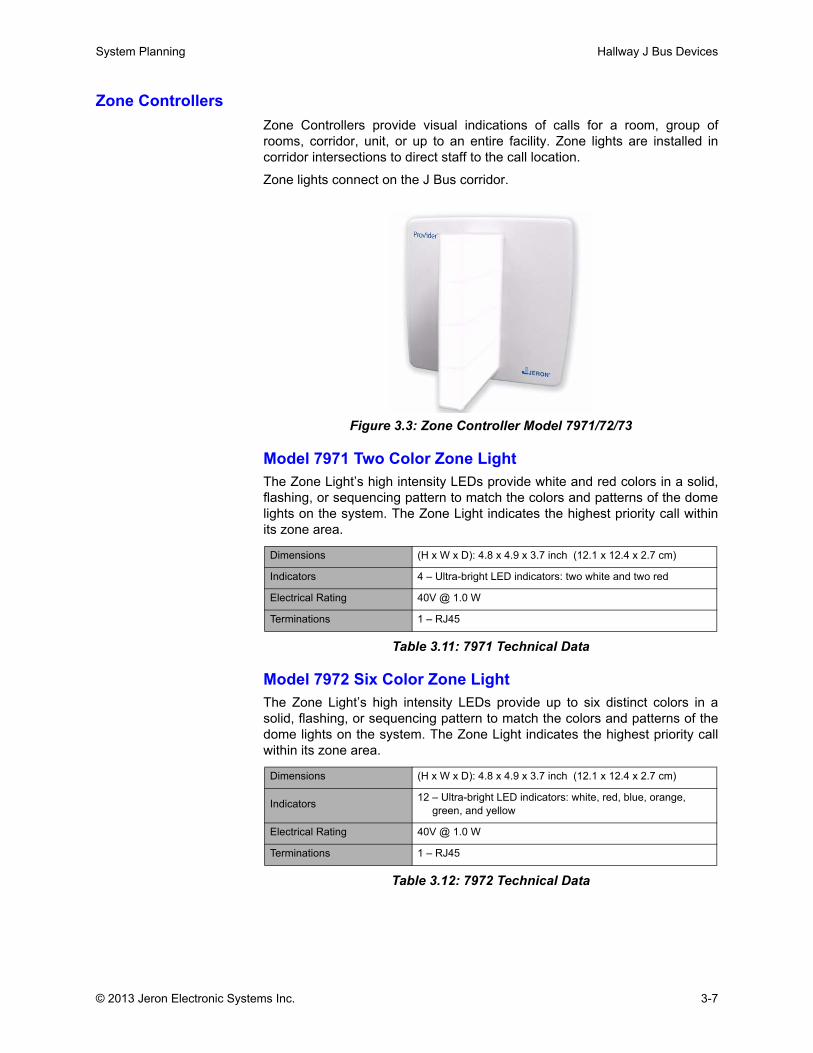
Zone ControllersZone Controllers provide visual indications of calls for a room, group ofrooms, corridor, unit, or up to an entire facility. Zone lights are installed incorridor intersections to direct staff to the call location.
Zone lights connect on the J Bus corridor.
Figure 3.3: Zone Controller Model 7971/72/73
Model 7971 Two Color Zone LightThe Zone Light’s high intensity LEDs provide white and red colors in a solid,flashing, or sequencing pattern to match the colors and patterns of the domelights on the system. The Zone Light indicates the highest priority call withinits zone area.
Table 3.11: 7971 Technical Data
Model 7972 Six Color Zone LightThe Zone Light’s high intensity LEDs provide up to six distinct colors in asolid, flashing, or sequencing pattern to match the colors and patterns of thedome lights on the system. The Zone Light indicates the highest priority callwithin its zone area.
Table 3.12: 7972 Technical Data
Dimensions (H x W x D): 4.8 x 4.9 x 3.7 inch (12.1 x 12.4 x 2.7 cm)
Indicators 4 – Ultra-bright LED indicators: two white and two red
Electrical Rating 40V @ 1.0 W
Terminations 1 – RJ45
Dimensions (H x W x D): 4.8 x 4.9 x 3.7 inch (12.1 x 12.4 x 2.7 cm)
Indicators 12 – Ultra-bright LED indicators: white, red, blue, orange, green, and yellow
Electrical Rating 40V @ 1.0 W
Terminations 1 – RJ45
© 2013 Jeron Electronic Systems Inc. 3-7
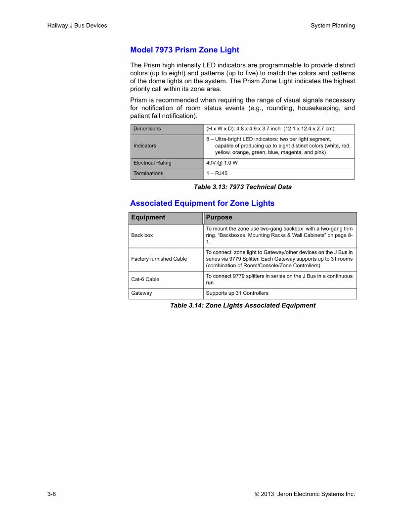
Hallway J Bus Devices System Planning
Model 7973 Prism Zone Light
The Prism high intensity LED indicators are programmable to provide distinctcolors (up to eight) and patterns (up to five) to match the colors and patternsof the dome lights on the system. The Prism Zone Light indicates the highestpriority call within its zone area.
Prism is recommended when requiring the range of visual signals necessaryfor notification of room status events (e.g., rounding, housekeeping, andpatient fall notification).
Table 3.13: 7973 Technical Data
Associated Equipment for Zone Lights
Table 3.14: Zone Lights Associated Equipment
Dimensions (H x W x D): 4.8 x 4.9 x 3.7 inch (12.1 x 12.4 x 2.7 cm)
Indicators8 – Ultra-bright LED indicators: two per light segment, capable of producing up to eight distinct colors (white, red, yellow, orange, green, blue, magenta, and pink)
Electrical Rating 40V @ 1.0 W
Terminations 1 – RJ45
Equipment Purpose
Back boxTo mount the zone use two-gang backbox with a two-gang trim ring. “Backboxes, Mounting Racks & Wall Cabinets” on page 8-1.
Factory furnished Cable To connect zone light to Gateway/other devices on the J Bus in series via 9779 Splitter. Each Gateway supports up to 31 rooms (combination of Room/Console/Zone Controllers)
Cat-6 Cable To connect 9779 splitters in series on the J Bus in a continuous run
Gateway Supports up 31 Controllers
3-8 © 2013 Jeron Electronic Systems Inc.

Chapter 4: Patient Rooms & Staff Stations

.
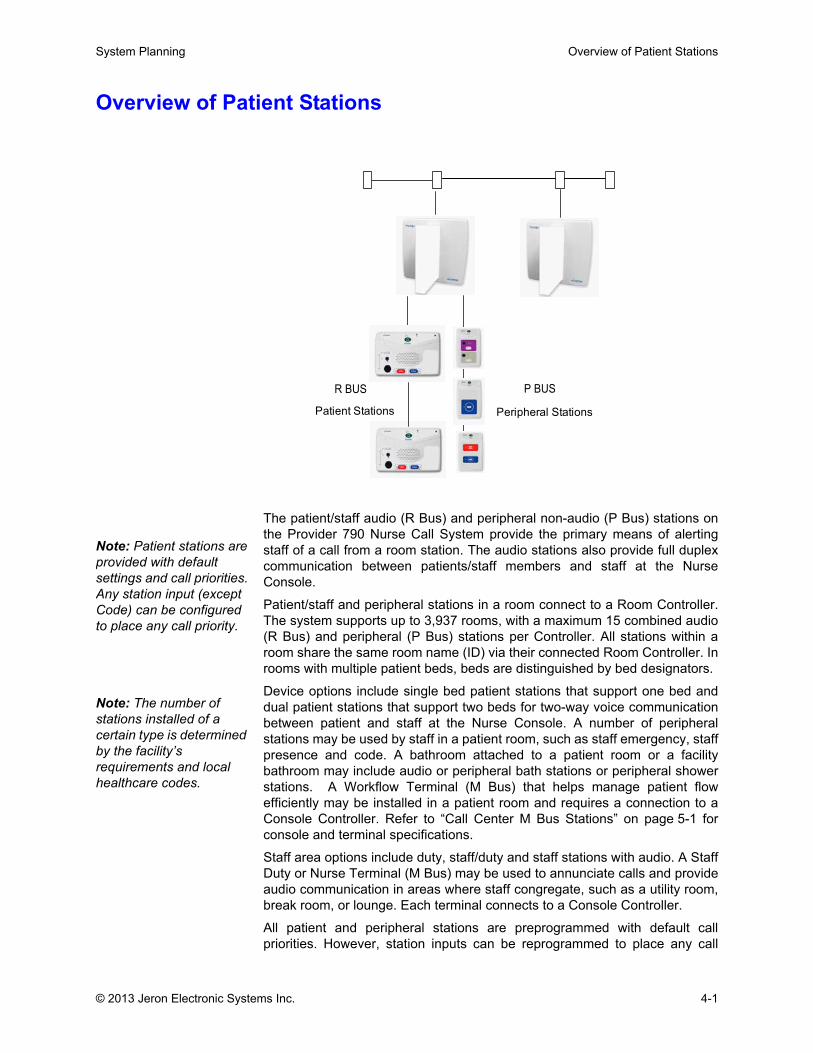
System Planning Overview of Patient Stations
Overview of Patient Stations
The patient/staff audio (R Bus) and peripheral non-audio (P Bus) stations onthe Provider 790 Nurse Call System provide the primary means of alertingstaff of a call from a room station. The audio stations also provide full duplexcommunication between patients/staff members and staff at the NurseConsole.
Patient/staff and peripheral stations in a room connect to a Room Controller.The system supports up to 3,937 rooms, with a maximum 15 combined audio(R Bus) and peripheral (P Bus) stations per Controller. All stations within aroom share the same room name (ID) via their connected Room Controller. Inrooms with multiple patient beds, beds are distinguished by bed designators.
Device options include single bed patient stations that support one bed anddual patient stations that support two beds for two-way voice communicationbetween patient and staff at the Nurse Console. A number of peripheralstations may be used by staff in a patient room, such as staff emergency, staffpresence and code. A bathroom attached to a patient room or a facilitybathroom may include audio or peripheral bath stations or peripheral showerstations. A Workflow Terminal (M Bus) that helps manage patient flowefficiently may be installed in a patient room and requires a connection to aConsole Controller. Refer to “Call Center M Bus Stations” on page 5-1 forconsole and terminal specifications.
Staff area options include duty, staff/duty and staff stations with audio. A StaffDuty or Nurse Terminal (M Bus) may be used to annunciate calls and provideaudio communication in areas where staff congregate, such as a utility room,break room, or lounge. Each terminal connects to a Console Controller.
All patient and peripheral stations are preprogrammed with default callpriorities. However, station inputs can be reprogrammed to place any call
Peripheral Stations
P BUS
Patient Stations
R BUS
Note: Patient stations are provided with default settings and call priorities. Any station input (except Code) can be configured to place any call priority.
Note: The number of stations installed of a certain type is determined by the facility’s requirements and local healthcare codes.
© 2013 Jeron Electronic Systems Inc. 4-1

Overview of Patient Stations System Planning
priority. In addition, button labels are customizable. For example, if a roomrequires a station for staff presence in addition to staff emergency, a Model7940 Procedure, Presence and Bed Management Station may be used. Thestation is equipped with four preprogrammed buttons that can bereprogrammed for any call type/staff registration. All four of the button labelsare replaceable. Four patient station models are equipped with twoprogrammable buttons and labels for any call type. For a list of stations withcustomizable buttons, refer to page 4-16.
Station enclosures are flame retardant UL 945VA PC/ABS blend polymericmaterial.
4-2 © 2013 Jeron Electronic Systems Inc.
System Planning Audio R Bus Stations
Audio R Bus StationsMost audio R Bus stations have audio capability and enable full-duplex twoway voice communication between patient/staff and staff members at theNurse Console.
Each input on a station comes with a default call-in priority setting that can bechanged in programming. Stations are equipped with a cancel button that, inaddition to canceling calls placed from the stations themselves, areconfigurable to selectively cancel any level of call-in on other stations withinthe same room.
The stations described below are categorized according to their typicallocation in the facility. However, flexibility in programming station buttons withdifferent call priorities allows stations to be used for other purposes based onthe facility’s needs.
Regardless of the facility location selected, caution must be taken whenmounting full duplex audio stations. Avoid blocking speaker or microphoneapertures on the front of audio station enclosures. Blocking or masking eitherspeaker or microphone may interfere with the full duplex audio operation andcause unwanted attenuation, echo, or feedback locally as well as remotely onmasters and handsets.
The stations connect in series to a Room Controller on the R Bus port via Cat-5 or better cable. The stations share the controller’s room name (ID),assigned in programming.
Patient Room Audio StationsPatient stations enable patients to place calls to the Nurse Console forassistance. Six patient stations models are available for different room types.When a call is answered, full-duplex two way voice communication is enabledeither through a pillow speaker (when using muting patient station Models7923 or 7924) or through the wall speaker and panel mic (non-muting Models7920, 7922, 7925, 7926).
Each patient room may have a single patient station that supports one bed, adual patient station that supports two beds, or a combination of both. Patientsplace calls by pressing a button on the pillow speaker or callcord plugged intothe station (DIN jacks). The 1/4 inch jacks (Models 7920-7924) can connect tocallcords or auxiliary input devices for third party medical equipment.
Calls can also be placed from siderail feature beds connected to patientstations (Models 7920-7924) using the Model 9805 receptacle kit for eachbed. Models 7923 and 7924 allow siderail bed audio communicationcapability, while non-muting patient stations 7920, 7922, 7925, and 7926allow siderail feature bed exit alarm functionality only.
Models 7920-7924 are equipped with two programmable call buttons for staffuse for placing high priority calls. The buttons are preconfigured forEmergency and Code but can be configured and relabeled during setup.Patient stations are equipped with TV connections. Television must be ULhospital grade, digital control. Only 7923 and 7924 mute TV audio duringnurse call audio connection. Individual TV connections per bed are availableon the 7921, 7924, and 7926.
Exercise caution when planning audio station location and mounting to ensure quality of full duplex audio will be preserved.
Note: Model 7905 Enhanced Pillow Speakers may be used with both muting and non-muting patient stations. When used with non-muting stations 7920, 7921, 7925, or 7926 ,the dedicated nurse call buttons (Nurse, Water, Pain, and Toilet) and auxiliary controls will operate. Nurse call audio will be routed through the pillow speaker only when used in conjunction with muting patient stations 7923 and 7924.
© 2013 Jeron Electronic Systems Inc. 4-3

Audio R Bus Stations System Planning
Patient stations may be equipped with Model 7906 AUX Modules that provideoutput to a lighting control via the pillow speakers with auxiliary buttons(Models 7902, 7904 and 7905). Lighting control module is provided by others.Patient stations are typically mounted in the headwalls above or adjacent tothe patient bed.The stations connect in series to a Room Controller, typically with a domelight.
4-4 © 2013 Jeron Electronic Systems Inc.
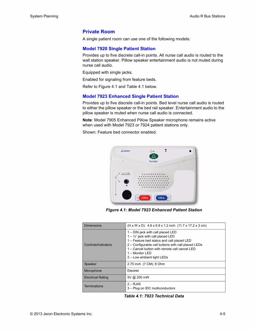
System Planning Audio R Bus Stations
Private RoomA single patient room can use one of the following models:
Model 7920 Single Patient StationProvides up to five discrete call-in points. All nurse call audio is routed to the wall station speaker. Pillow speaker entertainment audio is not muted during nurse call audio.
Equipped with single jacks.
Enabled for signaling from feature beds.
Refer to Figure 4.1 and Table 4.1 below.
Model 7923 Enhanced Single Patient StationProvides up to five discrete call-in points. Bed level nurse call audio is routed to either the pillow speaker or the bed rail speaker. Entertainment audio to the pillow speaker is muted when nurse call audio is connected.
Note: Model 7905 Enhanced Pillow Speaker microphone remains active when used with Model 7923 or 7924 patient stations only.
Shown: Feature bed connector enabled.
Figure 4.1: Model 7923 Enhanced Patient Station
Dimensions (H x W x D): 4.6 x 6.8 x 1.2 inch (11.7 x 17.2 x 3 cm)
Controls/Indicators
1 – DIN jack with call placed LED 1 – ¼” jack with call placed LED1 – Feature bed status and call placed LED2 – Configurable call buttons with call placed LEDs1 – Cancel button with remote call cancel LED1 – Monitor LED2 – Low ambient light LEDs
Speaker 2.75 inch (7 CM); 8 Ohm
Microphone Electret
Electrical Rating 5V @ 200 mW
Terminations 2 – RJ453 – Plug on IDC multiconductors
Table 4.1: 7923 Technical Data
© 2013 Jeron Electronic Systems Inc. 4-5
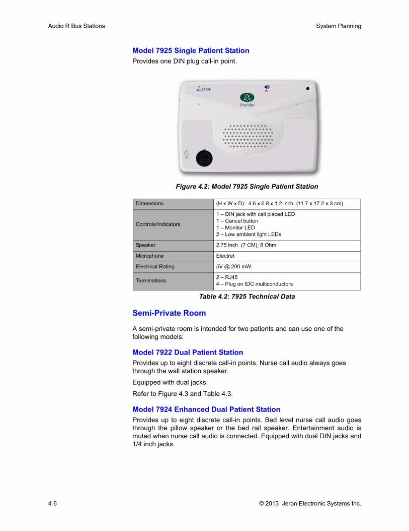
Audio R Bus Stations System Planning
Model 7925 Single Patient StationProvides one DIN plug call-in point.
Figure 4.2: Model 7925 Single Patient Station
Semi-Private Room
A semi-private room is intended for two patients and can use one of the following models:
Model 7922 Dual Patient StationProvides up to eight discrete call-in points. Nurse call audio always goes through the wall station speaker.
Equipped with dual jacks.
Refer to Figure 4.3 and Table 4.3.
Model 7924 Enhanced Dual Patient StationProvides up to eight discrete call-in points. Bed level nurse call audio goesthrough the pillow speaker or the bed rail speaker. Entertainment audio ismuted when nurse call audio is connected. Equipped with dual DIN jacks and1/4 inch jacks.
Dimensions (H x W x D): 4.6 x 6.8 x 1.2 inch (11.7 x 17.2 x 3 cm)
Controls/Indicators
1 – DIN jack with call placed LED1 – Cancel button 1 – Monitor LED2 – Low ambient light LEDs
Speaker 2.75 inch (7 CM); 8 Ohm
Microphone Electret
Electrical Rating 5V @ 200 mW
Terminations 2 – RJ454 – Plug on IDC multiconductors
Table 4.2: 7925 Technical Data
4-6 © 2013 Jeron Electronic Systems Inc.
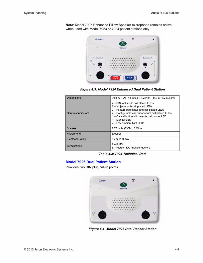
System Planning Audio R Bus Stations
Note: Model 7905 Enhanced Pillow Speaker microphone remains active when used with Model 7923 or 7924 patient stations only.
Figure 4.3: Model 7924 Enhanced Dual Patient Station
Model 7926 Dual Patient StationProvides two DIN plug call-in points.
Figure 4.4: Model 7926 Dual Patient Station
Dimensions (H x W x D): 4.6 x 6.8 x 1.2 inch (11.7 x 17.2 x 3 cm)
Controls/Indicators
2 – DIN jacks with call placed LEDs2 – ¼” jacks with call placed LEDs2 – Feature bed status and call placed LEDs2 – Configurable call buttons with call placed LEDs1 – Cancel button with remote call cancel LED1 – Monitor LED2 – Low ambient light LEDs
Speaker 2.75 inch (7 CM); 8 Ohm
Microphone Electret
Electrical Rating 5V @ 200 mW
Terminations 2 – RJ456 – Plug on IDC multiconductors
Table 4.3: 7924 Technical Data
© 2013 Jeron Electronic Systems Inc. 4-7
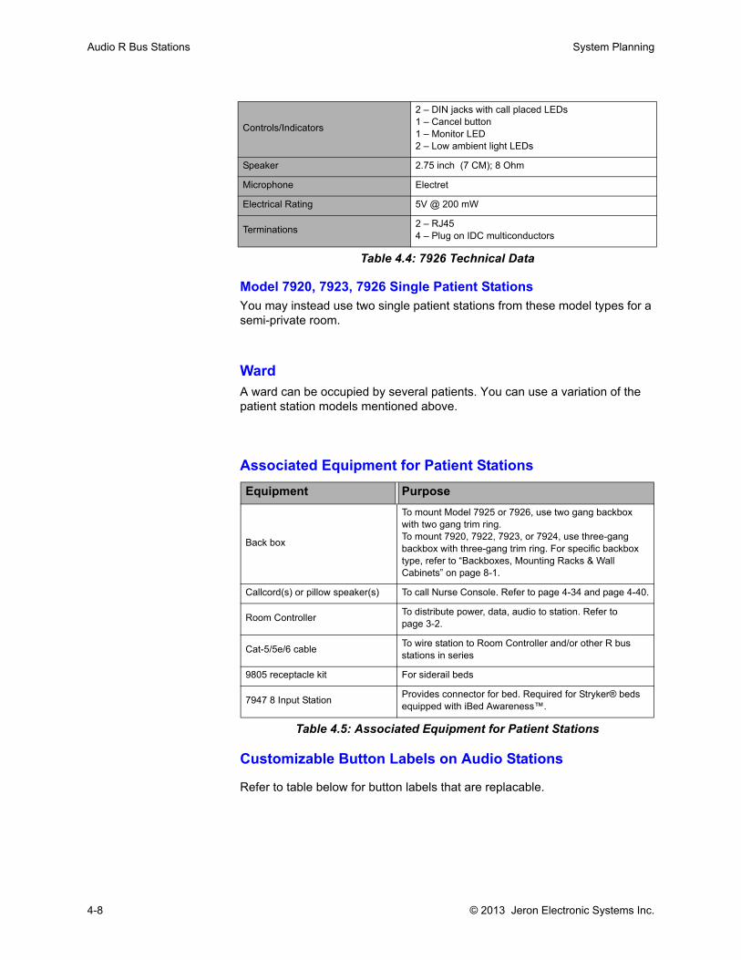
Audio R Bus Stations System Planning
Model 7920, 7923, 7926 Single Patient StationsYou may instead use two single patient stations from these model types for a semi-private room.
WardA ward can be occupied by several patients. You can use a variation of the patient station models mentioned above.
Associated Equipment for Patient Stations
Table 4.5: Associated Equipment for Patient Stations
Customizable Button Labels on Audio Stations
Refer to table below for button labels that are replacable.
Controls/Indicators
2 – DIN jacks with call placed LEDs1 – Cancel button 1 – Monitor LED2 – Low ambient light LEDs
Speaker 2.75 inch (7 CM); 8 Ohm
Microphone Electret
Electrical Rating 5V @ 200 mW
Terminations 2 – RJ454 – Plug on IDC multiconductors
Table 4.4: 7926 Technical Data
Equipment Purpose
Back box
To mount Model 7925 or 7926, use two gang backbox with two gang trim ring.To mount 7920, 7922, 7923, or 7924, use three-gang backbox with three-gang trim ring. For specific backbox type, refer to “Backboxes, Mounting Racks & Wall Cabinets” on page 8-1.
Callcord(s) or pillow speaker(s) To call Nurse Console. Refer to page 4-34 and page 4-40.
Room Controller To distribute power, data, audio to station. Refer to page 3-2.
Cat-5/5e/6 cable To wire station to Room Controller and/or other R bus stations in series
9805 receptacle kit For siderail beds
7947 8 Input Station Provides connector for bed. Required for Stryker® beds equipped with iBed Awareness™.
4-8 © 2013 Jeron Electronic Systems Inc.
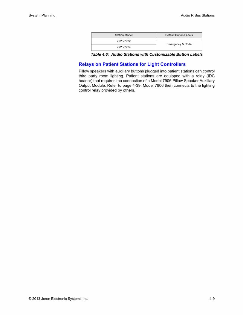
System Planning Audio R Bus Stations
Relays on Patient Stations for Light ControllersPillow speakers with auxiliary buttons plugged into patient stations can controlthird party room lighting. Patient stations are equipped with a relay (IDCheader) that requires the connection of a Model 7906 Pillow Speaker AuxiliaryOutput Module. Refer to page 4-39. Model 7906 then connects to the lightingcontrol relay provided by others.
Station Model Default Button Labels
7920/7922Emergency & Code
7923/7924
Table 4.6: Audio Stations with Customizable Button Labels
© 2013 Jeron Electronic Systems Inc. 4-9
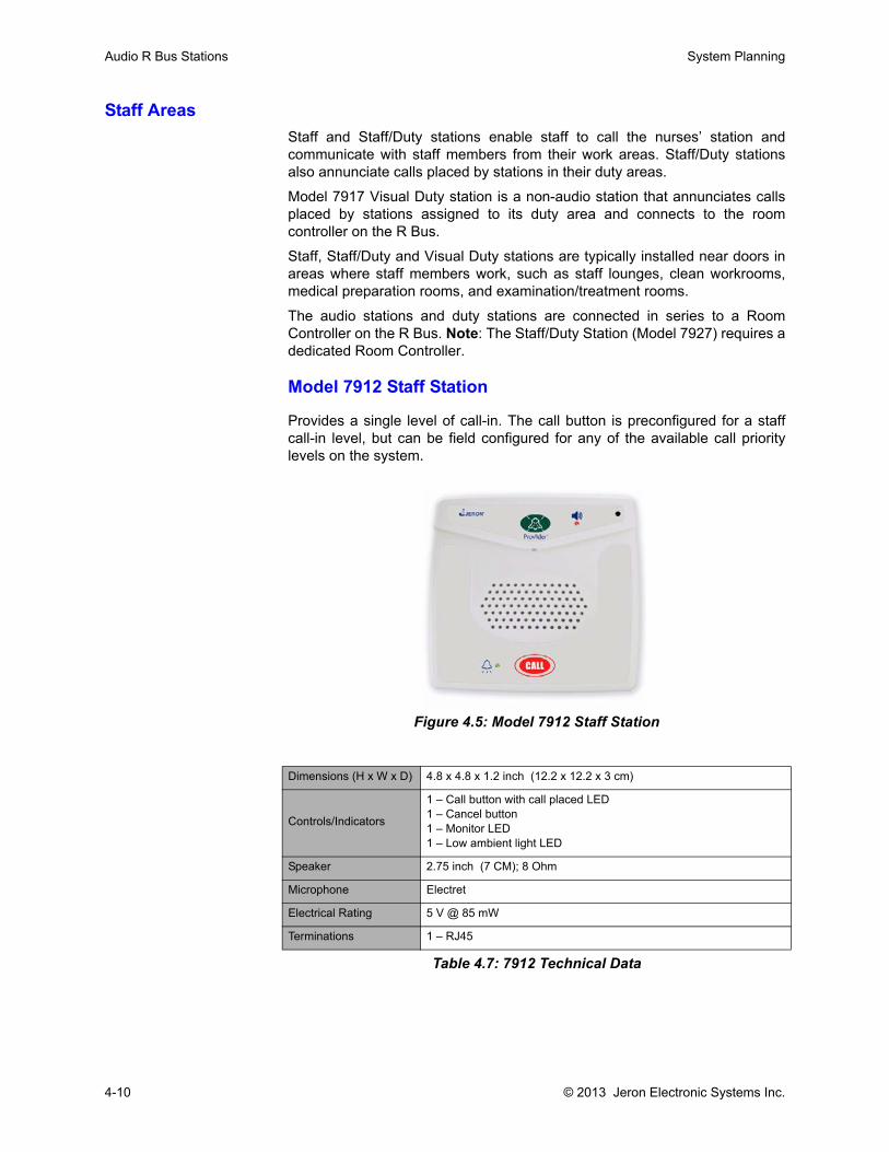
Audio R Bus Stations System Planning
Staff AreasStaff and Staff/Duty stations enable staff to call the nurses’ station andcommunicate with staff members from their work areas. Staff/Duty stationsalso annunciate calls placed by stations in their duty areas.
Model 7917 Visual Duty station is a non-audio station that annunciates callsplaced by stations assigned to its duty area and connects to the roomcontroller on the R Bus.
Staff, Staff/Duty and Visual Duty stations are typically installed near doors inareas where staff members work, such as staff lounges, clean workrooms,medical preparation rooms, and examination/treatment rooms.
The audio stations and duty stations are connected in series to a RoomController on the R Bus. Note: The Staff/Duty Station (Model 7927) requires adedicated Room Controller.
Model 7912 Staff Station
Provides a single level of call-in. The call button is preconfigured for a staffcall-in level, but can be field configured for any of the available call prioritylevels on the system.
Figure 4.5: Model 7912 Staff Station
Dimensions (H x W x D) 4.8 x 4.8 x 1.2 inch (12.2 x 12.2 x 3 cm)
Controls/Indicators
1 – Call button with call placed LED1 – Cancel button1 – Monitor LED1 – Low ambient light LED
Speaker 2.75 inch (7 CM); 8 Ohm
Microphone Electret
Electrical Rating 5 V @ 85 mW
Terminations 1 – RJ45
Table 4.7: 7912 Technical Data
4-10 © 2013 Jeron Electronic Systems Inc.
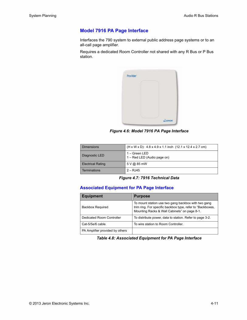
System Planning Audio R Bus Stations
Model 7916 PA Page Interface
Interfaces the 790 system to external public address page systems or to an all-call page amplifier.
Requires a dedicated Room Controller not shared with any R Bus or P Bus station.
Figure 4.6: Model 7916 PA Page Interface
Figure 4.7: 7916 Technical Data
Associated Equipment for PA Page Interface
Table 4.8: Associated Equipment for PA Page Interface
Dimensions (H x W x D): 4.8 x 4.9 x 1.1 inch (12.1 x 12.4 x 2.7 cm)
Diagnostic LED 1 – Green LED1 – Red LED (Audio page on)
Electrical Rating 5 V @ 85 mW
Terminations 2 – RJ45
Equipment Purpose
Backbox RequiredTo mount station use two gang backbox with two gang trim ring. For specific backbox type, refer to “Backboxes, Mounting Racks & Wall Cabinets” on page 8-1.
Dedicated Room Controller To distribute power, data to station. Refer to page 3-2.
Cat-5/5e/6 cable To wire station to Room Controller.
PA Amplifier provided by others
© 2013 Jeron Electronic Systems Inc. 4-11
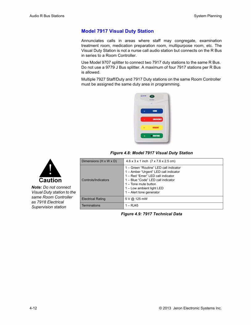
Audio R Bus Stations System Planning
Model 7917 Visual Duty Station
Annunciates calls in areas where staff may congregate, examinationtreatment room, medication preparation room, multipurpose room, etc. TheVisual Duty Station is not a nurse call audio station but connects on the R Busin series to a Room Controller.
Use Model 9707 splitter to connect two 7917 duty stations to the same R Bus. Do not use a 9779 J Bus splitter. A maximum of four 7917 stations per R Bus is allowed.
Multiple 7927 Staff/Duty and 7917 Duty stations on the same Room Controller must be assigned the same duty area in programming.
Figure 4.8: Model 7917 Visual Duty Station
Figure 4.9: 7917 Technical Data
Dimensions (H x W x D) 4.6 x 3 x 1 inch (7 x 7.6 x 2.5 cm)
Controls/Indicators
1 – Green “Routine” LED call indicator1 – Amber “Urgent” LED call indicator1 – Red “Emer” LED call indicator1 – Blue “Code” LED call indicator1 – Tone mute button1 – Low ambient light LED1 – Alert tone generator
Electrical Rating 5 V @ 125 mW
Terminations 1 – RJ45
Note: Do not connect Visual Duty station to the same Room Controller as 7918 Electrical Supervision station
4-12 © 2013 Jeron Electronic Systems Inc.
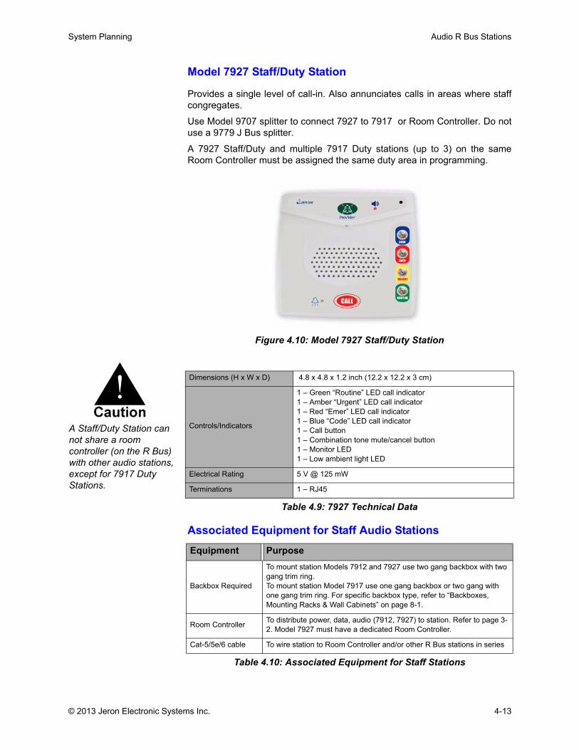
System Planning Audio R Bus Stations
Model 7927 Staff/Duty Station
Provides a single level of call-in. Also annunciates calls in areas where staffcongregates.
Use Model 9707 splitter to connect 7927 to 7917 or Room Controller. Do notuse a 9779 J Bus splitter.
A 7927 Staff/Duty and multiple 7917 Duty stations (up to 3) on the sameRoom Controller must be assigned the same duty area in programming.
Figure 4.10: Model 7927 Staff/Duty Station
Associated Equipment for Staff Audio Stations
Table 4.10: Associated Equipment for Staff Stations
Dimensions (H x W x D) 4.8 x 4.8 x 1.2 inch (12.2 x 12.2 x 3 cm)
Controls/Indicators
1 – Green “Routine” LED call indicator1 – Amber “Urgent” LED call indicator1 – Red “Emer” LED call indicator1 – Blue “Code” LED call indicator1 – Call button 1 – Combination tone mute/cancel button1 – Monitor LED1 – Low ambient light LED
Electrical Rating 5 V @ 125 mW
Terminations 1 – RJ45
Table 4.9: 7927 Technical Data
Equipment Purpose
Backbox Required
To mount station Models 7912 and 7927 use two gang backbox with two gang trim ring. To mount station Model 7917 use one gang backbox or two gang with one gang trim ring. For specific backbox type, refer to “Backboxes, Mounting Racks & Wall Cabinets” on page 8-1.
Room Controller To distribute power, data, audio (7912, 7927) to station. Refer to page 3-2. Model 7927 must have a dedicated Room Controller.
Cat-5/5e/6 cable To wire station to Room Controller and/or other R Bus stations in series
A Staff/Duty Station can not share a room controller (on the R Bus) with other audio stations, except for 7917 Duty Stations.
© 2013 Jeron Electronic Systems Inc. 4-13
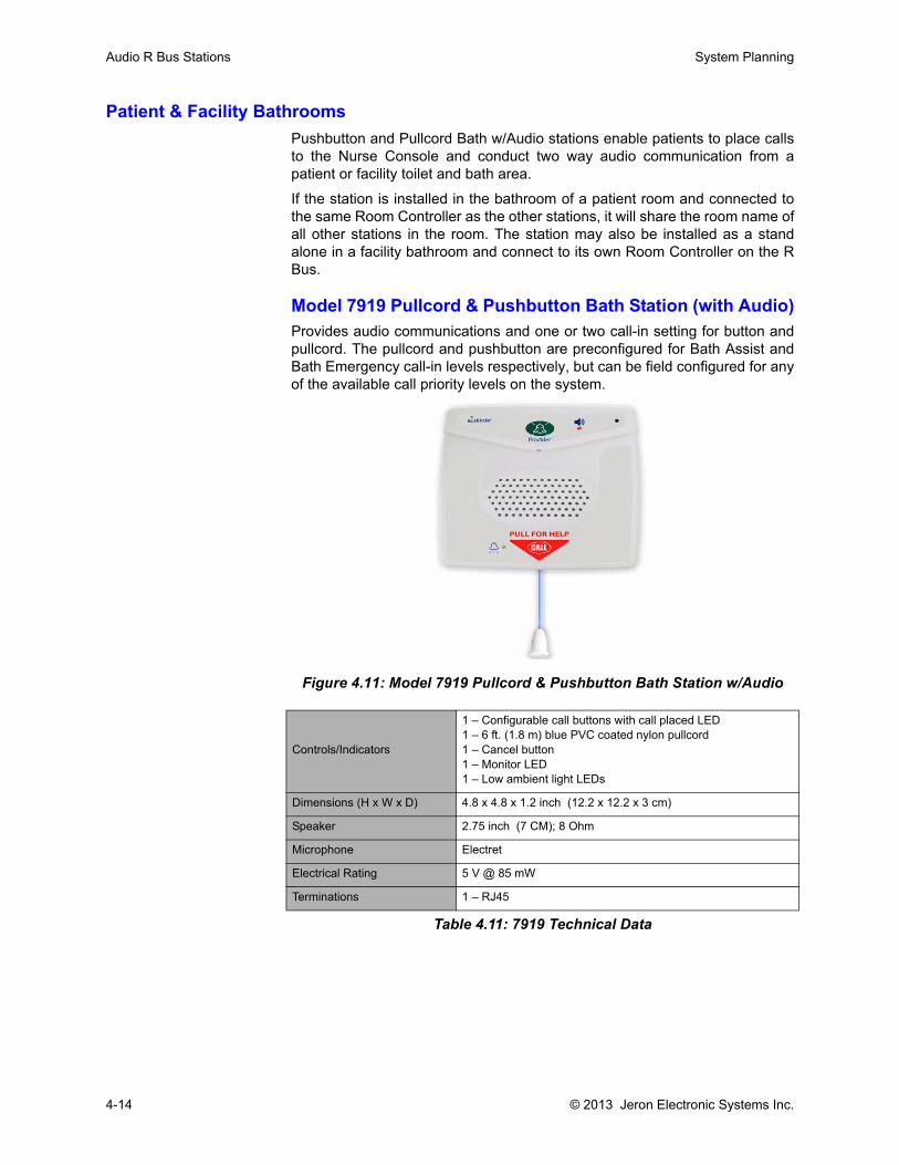
Audio R Bus Stations System Planning
Patient & Facility BathroomsPushbutton and Pullcord Bath w/Audio stations enable patients to place callsto the Nurse Console and conduct two way audio communication from apatient or facility toilet and bath area.
If the station is installed in the bathroom of a patient room and connected tothe same Room Controller as the other stations, it will share the room name ofall other stations in the room. The station may also be installed as a standalone in a facility bathroom and connect to its own Room Controller on the RBus.
Model 7919 Pullcord & Pushbutton Bath Station (with Audio)Provides audio communications and one or two call-in setting for button andpullcord. The pullcord and pushbutton are preconfigured for Bath Assist andBath Emergency call-in levels respectively, but can be field configured for anyof the available call priority levels on the system.
Figure 4.11: Model 7919 Pullcord & Pushbutton Bath Station w/Audio
Controls/Indicators
1 – Configurable call buttons with call placed LED1 – 6 ft. (1.8 m) blue PVC coated nylon pullcord1 – Cancel button1 – Monitor LED1 – Low ambient light LEDs
Dimensions (H x W x D) 4.8 x 4.8 x 1.2 inch (12.2 x 12.2 x 3 cm)
Speaker 2.75 inch (7 CM); 8 Ohm
Microphone Electret
Electrical Rating 5 V @ 85 mW
Terminations 1 – RJ45
Table 4.11: 7919 Technical Data
4-14 © 2013 Jeron Electronic Systems Inc.
System Planning Audio R Bus Stations
Associated Equipment for Bath Stations
Table 4.12: Associated Equipment for Bath Stations
Equipment Purpose
Back boxTo mount station use two-gang box with two-gang trim ring. For specific backbox type, refer to “Backboxes, Mounting Racks & Wall Cabinets” on page 8-1.
Room Controller To distribute power, data, audio to station. Refer to page 3-2.
Cat-5/5e/6 cable To wire station to Room Controller, and/or other R Bus stations in series
© 2013 Jeron Electronic Systems Inc. 4-15
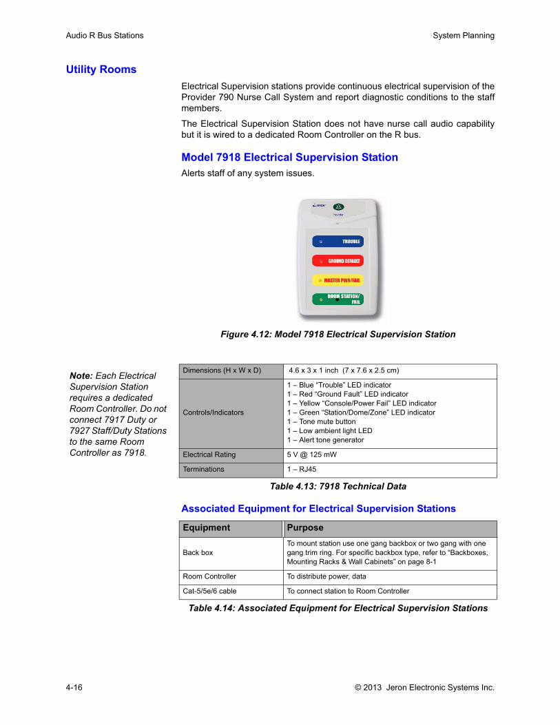
Audio R Bus Stations System Planning
Utility RoomsElectrical Supervision stations provide continuous electrical supervision of theProvider 790 Nurse Call System and report diagnostic conditions to the staffmembers.
The Electrical Supervision Station does not have nurse call audio capabilitybut it is wired to a dedicated Room Controller on the R bus.
Model 7918 Electrical Supervision StationAlerts staff of any system issues.
Figure 4.12: Model 7918 Electrical Supervision Station
Associated Equipment for Electrical Supervision Stations
Table 4.14: Associated Equipment for Electrical Supervision Stations
Dimensions (H x W x D) 4.6 x 3 x 1 inch (7 x 7.6 x 2.5 cm)
Controls/Indicators
1 – Blue “Trouble” LED indicator1 – Red “Ground Fault” LED indicator1 – Yellow “Console/Power Fail” LED indicator1 – Green “Station/Dome/Zone” LED indicator1 – Tone mute button1 – Low ambient light LED1 – Alert tone generator
Electrical Rating 5 V @ 125 mW
Terminations 1 – RJ45
Table 4.13: 7918 Technical Data
Equipment Purpose
Back boxTo mount station use one gang backbox or two gang with one gang trim ring. For specific backbox type, refer to “Backboxes, Mounting Racks & Wall Cabinets” on page 8-1
Room Controller To distribute power, data
Cat-5/5e/6 cable To connect station to Room Controller
Note: Each Electrical Supervision Station requires a dedicated Room Controller. Do not connect 7917 Duty or 7927 Staff/Duty Stations to the same Room Controller as 7918.
4-16 © 2013 Jeron Electronic Systems Inc.
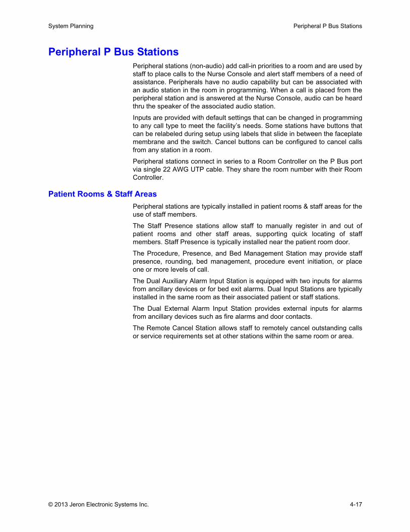
System Planning Peripheral P Bus Stations
Peripheral P Bus Stations Peripheral stations (non-audio) add call-in priorities to a room and are used bystaff to place calls to the Nurse Console and alert staff members of a need ofassistance. Peripherals have no audio capability but can be associated withan audio station in the room in programming. When a call is placed from theperipheral station and is answered at the Nurse Console, audio can be heardthru the speaker of the associated audio station.
Inputs are provided with default settings that can be changed in programmingto any call type to meet the facility’s needs. Some stations have buttons thatcan be relabeled during setup using labels that slide in between the faceplatemembrane and the switch. Cancel buttons can be configured to cancel callsfrom any station in a room.
Peripheral stations connect in series to a Room Controller on the P Bus portvia single 22 AWG UTP cable. They share the room number with their RoomController.
Patient Rooms & Staff AreasPeripheral stations are typically installed in patient rooms & staff areas for theuse of staff members.
The Staff Presence stations allow staff to manually register in and out ofpatient rooms and other staff areas, supporting quick locating of staffmembers. Staff Presence is typically installed near the patient room door.
The Procedure, Presence, and Bed Management Station may provide staffpresence, rounding, bed management, procedure event initiation, or placeone or more levels of call.
The Dual Auxiliary Alarm Input Station is equipped with two inputs for alarmsfrom ancillary devices or for bed exit alarms. Dual Input Stations are typicallyinstalled in the same room as their associated patient or staff stations.
The Dual External Alarm Input Station provides external inputs for alarmsfrom ancillary devices such as fire alarms and door contacts.
The Remote Cancel Station allows staff to remotely cancel outstanding callsor service requirements set at other stations within the same room or area.
© 2013 Jeron Electronic Systems Inc. 4-17
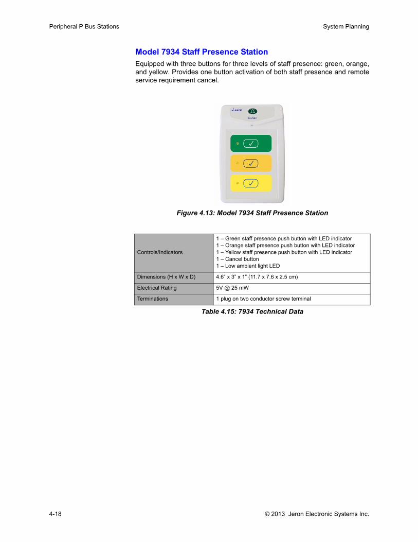
Peripheral P Bus Stations System Planning
Model 7934 Staff Presence StationEquipped with three buttons for three levels of staff presence: green, orange,and yellow. Provides one button activation of both staff presence and remoteservice requirement cancel.
Figure 4.13: Model 7934 Staff Presence Station
Controls/Indicators
1 – Green staff presence push button with LED indicator1 – Orange staff presence push button with LED indicator1 – Yellow staff presence push button with LED indicator1 – Cancel button1 – Low ambient light LED
Dimensions (H x W x D) 4.6” x 3” x 1” (11.7 x 7.6 x 2.5 cm)
Electrical Rating 5V @ 25 mW
Terminations 1 plug on two conductor screw terminal
Table 4.15: 7934 Technical Data
4-18 © 2013 Jeron Electronic Systems Inc.
System Planning Peripheral P Bus Stations
Model 7937 Remote Cancel Station
The Remote Cancel station is configurable to selectively cancel all or selectlevels of calls and service requirements set on other stations within the sameroom. The station is installed in any room equipped with call stations thatrequire a cancel point.
Figure 4.14: Model 7937 Remote Cancel Station
Associated Equipment for Remote Cancel Stations
Table 4.17: 7937 Associated Equipment
Controls/Indicators 1 – Cancel button1 – Low ambient light LED
Dimensions (H x W x D) 4.6” x 3” x 1” (11.7 x 7.6 x 2.5 cm)
Electrical Rating 5V @ 25 mW
Terminations 1 plug on two conductor screw terminal
Table 4.16: 7937 Technical Data
Equipment Purpose
Back boxTo mount station use one gang backbox or two gang with one gang trim ring. For specific backbox type, refer to “Backboxes, Mounting Racks & Wall Cabinets” on page 8-1
Room Controller To distribute power, data. Refer to page 3-2.
Pair of 22 AWG wires To wire station to Room Controller and/or other P Bus stations in series
Call Stations To remotely cancel calls placed in a room from this station
© 2013 Jeron Electronic Systems Inc. 4-19
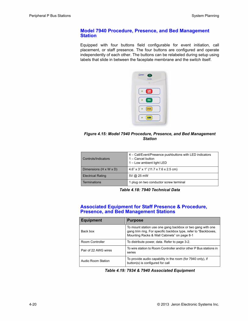
Peripheral P Bus Stations System Planning
Model 7940 Procedure, Presence, and Bed Management Station
Equipped with four buttons field configurable for event initiation, callplacement, or staff presence. The four buttons are configured and operateindependently of each other. The buttons can be relabeled during setup usinglabels that slide in between the faceplate membrane and the switch itself.
Figure 4.15: Model 7940 Procedure, Presence, and Bed Management Station
Associated Equipment for Staff Presence & Procedure, Presence, and Bed Management Stations
Table 4.19: 7934 & 7940 Associated Equipment
Controls/Indicators4 – Call/Event/Presence pushbuttons with LED indicators1 – Cancel button1 – Low ambient light LED
Dimensions (H x W x D) 4.6” x 3” x 1” (11.7 x 7.6 x 2.5 cm)
Electrical Rating 5V @ 25 mW
Terminations 1 plug on two conductor screw terminal
Table 4.18: 7940 Technical Data
Equipment Purpose
Back boxTo mount station use one gang backbox or two gang with one gang trim ring. For specific backbox type, refer to “Backboxes, Mounting Racks & Wall Cabinets” on page 8-1
Room Controller To distribute power, data. Refer to page 3-2.
Pair of 22 AWG wires To wire station to Room Controller and/or other P Bus stations in series
Audio Room Station To provide audio capability in the room (for 7940 only), if button(s) is configured for call
4-20 © 2013 Jeron Electronic Systems Inc.
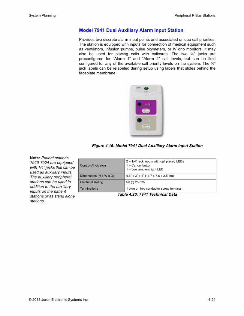
System Planning Peripheral P Bus Stations
Model 7941 Dual Auxiliary Alarm Input Station
Provides two discrete alarm input points and associated unique call priorities.The station is equipped with inputs for connection of medical equipment suchas ventilators, infusion pumps, pulse oxymeters, or IV drip monitors. It mayalso be used for placing calls with callcords. The two ¼” jacks arepreconfigured for “Alarm 1” and “Alarm 2” call levels, but can be fieldconfigured for any of the available call priority levels on the system. The ¼”jack labels can be relabeled during setup using labels that slides behind thefaceplate membrane.
Figure 4.16: Model 7941 Dual Auxiliary Alarm Input Station
Table 4.20: 7941 Technical Data
Controls/Indicators2 – 1/4” jack inputs with call placed LEDs1 – Cancel button1 – Low ambient light LED
Dimensions (H x W x D) 4.6” x 3” x 1” (11.7 x 7.6 x 2.5 cm)
Electrical Rating 5V @ 25 mW
Terminations 1 plug on two conductor screw terminal
Note: Patient stations 7920-7924 are equipped with 1/4” jacks that can be used as auxiliary inputs. The auxiliary peripheral stations can be used in addition to the auxiliary inputs on the patient stations or as stand alone stations.
© 2013 Jeron Electronic Systems Inc. 4-21
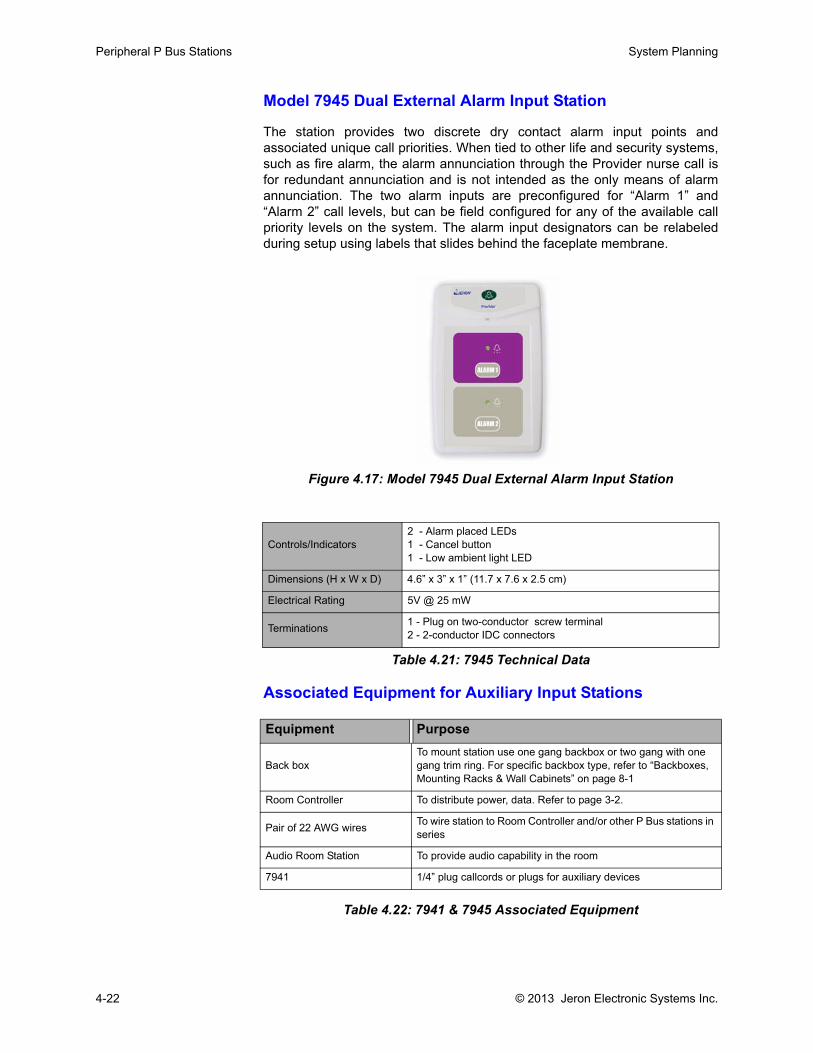
Peripheral P Bus Stations System Planning
Model 7945 Dual External Alarm Input Station
The station provides two discrete dry contact alarm input points andassociated unique call priorities. When tied to other life and security systems,such as fire alarm, the alarm annunciation through the Provider nurse call isfor redundant annunciation and is not intended as the only means of alarmannunciation. The two alarm inputs are preconfigured for “Alarm 1” and“Alarm 2” call levels, but can be field configured for any of the available callpriority levels on the system. The alarm input designators can be relabeledduring setup using labels that slides behind the faceplate membrane.
Figure 4.17: Model 7945 Dual External Alarm Input Station
Associated Equipment for Auxiliary Input Stations
Table 4.22: 7941 & 7945 Associated Equipment
Controls/Indicators2 - Alarm placed LEDs1 - Cancel button1 - Low ambient light LED
Dimensions (H x W x D) 4.6” x 3” x 1” (11.7 x 7.6 x 2.5 cm)
Electrical Rating 5V @ 25 mW
Terminations 1 - Plug on two-conductor screw terminal2 - 2-conductor IDC connectors
Table 4.21: 7945 Technical Data
Equipment Purpose
Back boxTo mount station use one gang backbox or two gang with one gang trim ring. For specific backbox type, refer to “Backboxes, Mounting Racks & Wall Cabinets” on page 8-1
Room Controller To distribute power, data. Refer to page 3-2.
Pair of 22 AWG wires To wire station to Room Controller and/or other P Bus stations in series
Audio Room Station To provide audio capability in the room
7941 1/4” plug callcords or plugs for auxiliary devices
4-22 © 2013 Jeron Electronic Systems Inc.
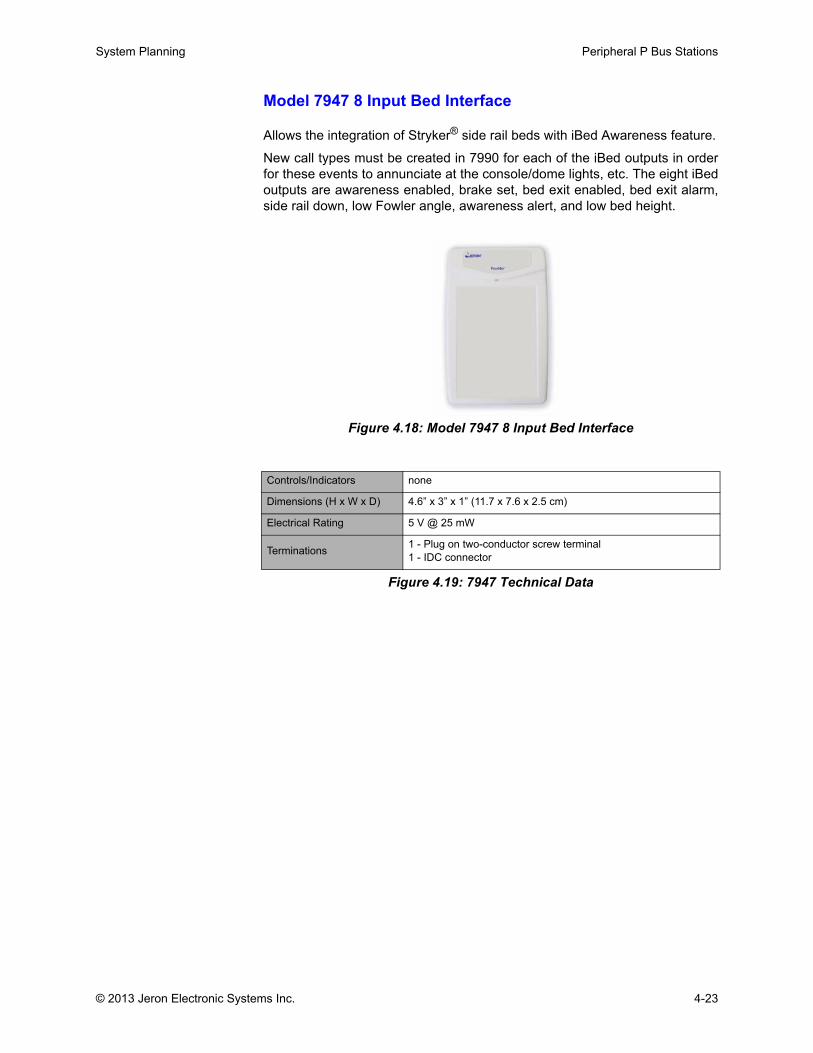
System Planning Peripheral P Bus Stations
Model 7947 8 Input Bed Interface
Allows the integration of Stryker® side rail beds with iBed Awareness feature.
New call types must be created in 7990 for each of the iBed outputs in orderfor these events to annunciate at the console/dome lights, etc. The eight iBedoutputs are awareness enabled, brake set, bed exit enabled, bed exit alarm,side rail down, low Fowler angle, awareness alert, and low bed height.
Figure 4.18: Model 7947 8 Input Bed Interface
Figure 4.19: 7947 Technical Data
Controls/Indicators none
Dimensions (H x W x D) 4.6” x 3” x 1” (11.7 x 7.6 x 2.5 cm)
Electrical Rating 5 V @ 25 mW
Terminations 1 - Plug on two-conductor screw terminal1 - IDC connector
© 2013 Jeron Electronic Systems Inc. 4-23
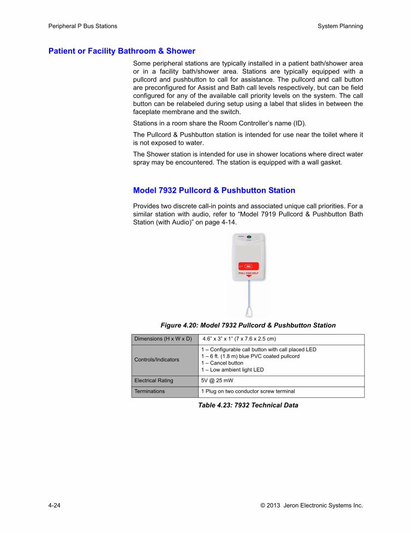
Peripheral P Bus Stations System Planning
Patient or Facility Bathroom & ShowerSome peripheral stations are typically installed in a patient bath/shower areaor in a facility bath/shower area. Stations are typically equipped with apullcord and pushbutton to call for assistance. The pullcord and call buttonare preconfigured for Assist and Bath call levels respectively, but can be fieldconfigured for any of the available call priority levels on the system. The callbutton can be relabeled during setup using a label that slides in between thefaceplate membrane and the switch.
Stations in a room share the Room Controller’s name (ID).
The Pullcord & Pushbutton station is intended for use near the toilet where itis not exposed to water.
The Shower station is intended for use in shower locations where direct waterspray may be encountered. The station is equipped with a wall gasket.
Model 7932 Pullcord & Pushbutton Station
Provides two discrete call-in points and associated unique call priorities. For asimilar station with audio, refer to “Model 7919 Pullcord & Pushbutton BathStation (with Audio)” on page 4-14.
Figure 4.20: Model 7932 Pullcord & Pushbutton Station
Table 4.23: 7932 Technical Data
Dimensions (H x W x D) 4.6” x 3” x 1” (7 x 7.6 x 2.5 cm)
Controls/Indicators
1 – Configurable call button with call placed LED1 – 6 ft. (1.8 m) blue PVC coated pullcord1 – Cancel button1 – Low ambient light LED
Electrical Rating 5V @ 25 mW
Terminations 1 Plug on two conductor screw terminal
4-24 © 2013 Jeron Electronic Systems Inc.
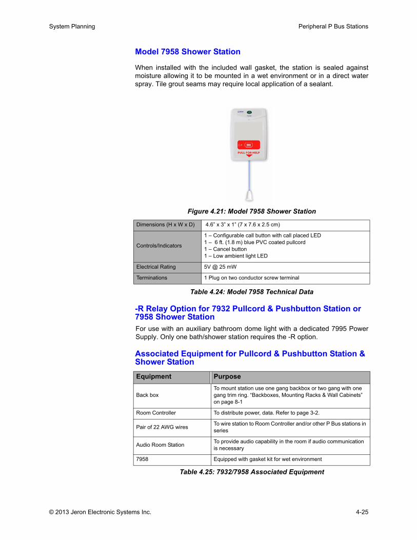
System Planning Peripheral P Bus Stations
Model 7958 Shower Station
When installed with the included wall gasket, the station is sealed againstmoisture allowing it to be mounted in a wet environment or in a direct waterspray. Tile grout seams may require local application of a sealant.
Figure 4.21: Model 7958 Shower Station
Table 4.24: Model 7958 Technical Data
-R Relay Option for 7932 Pullcord & Pushbutton Station or 7958 Shower StationFor use with an auxiliary bathroom dome light with a dedicated 7995 PowerSupply. Only one bath/shower station requires the -R option.
Associated Equipment for Pullcord & Pushbutton Station & Shower Station
Table 4.25: 7932/7958 Associated Equipment
Dimensions (H x W x D) 4.6” x 3” x 1” (7 x 7.6 x 2.5 cm)
Controls/Indicators
1 – Configurable call button with call placed LED1 – 6 ft. (1.8 m) blue PVC coated pullcord1 – Cancel button1 – Low ambient light LED
Electrical Rating 5V @ 25 mW
Terminations 1 Plug on two conductor screw terminal
Equipment Purpose
Back boxTo mount station use one gang backbox or two gang with one gang trim ring. “Backboxes, Mounting Racks & Wall Cabinets” on page 8-1
Room Controller To distribute power, data. Refer to page 3-2.
Pair of 22 AWG wires To wire station to Room Controller and/or other P Bus stations in series
Audio Room Station To provide audio capability in the room if audio communication is necessary
7958 Equipped with gasket kit for wet environment
© 2013 Jeron Electronic Systems Inc. 4-25
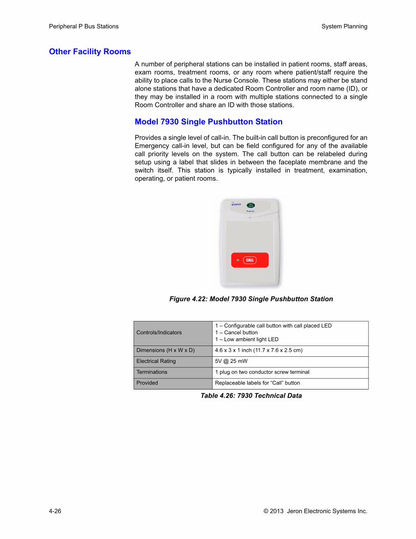
Peripheral P Bus Stations System Planning
Other Facility RoomsA number of peripheral stations can be installed in patient rooms, staff areas,exam rooms, treatment rooms, or any room where patient/staff require theability to place calls to the Nurse Console. These stations may either be standalone stations that have a dedicated Room Controller and room name (ID), orthey may be installed in a room with multiple stations connected to a singleRoom Controller and share an ID with those stations.
Model 7930 Single Pushbutton Station
Provides a single level of call-in. The built-in call button is preconfigured for anEmergency call-in level, but can be field configured for any of the availablecall priority levels on the system. The call button can be relabeled duringsetup using a label that slides in between the faceplate membrane and theswitch itself. This station is typically installed in treatment, examination,operating, or patient rooms.
Figure 4.22: Model 7930 Single Pushbutton Station
Controls/Indicators1 – Configurable call button with call placed LED1 – Cancel button1 – Low ambient light LED
Dimensions (H x W x D) 4.6 x 3 x 1 inch (11.7 x 7.6 x 2.5 cm)
Electrical Rating 5V @ 25 mW
Terminations 1 plug on two conductor screw terminal
Provided Replaceable labels for “Call” button
Table 4.26: 7930 Technical Data
4-26 © 2013 Jeron Electronic Systems Inc.
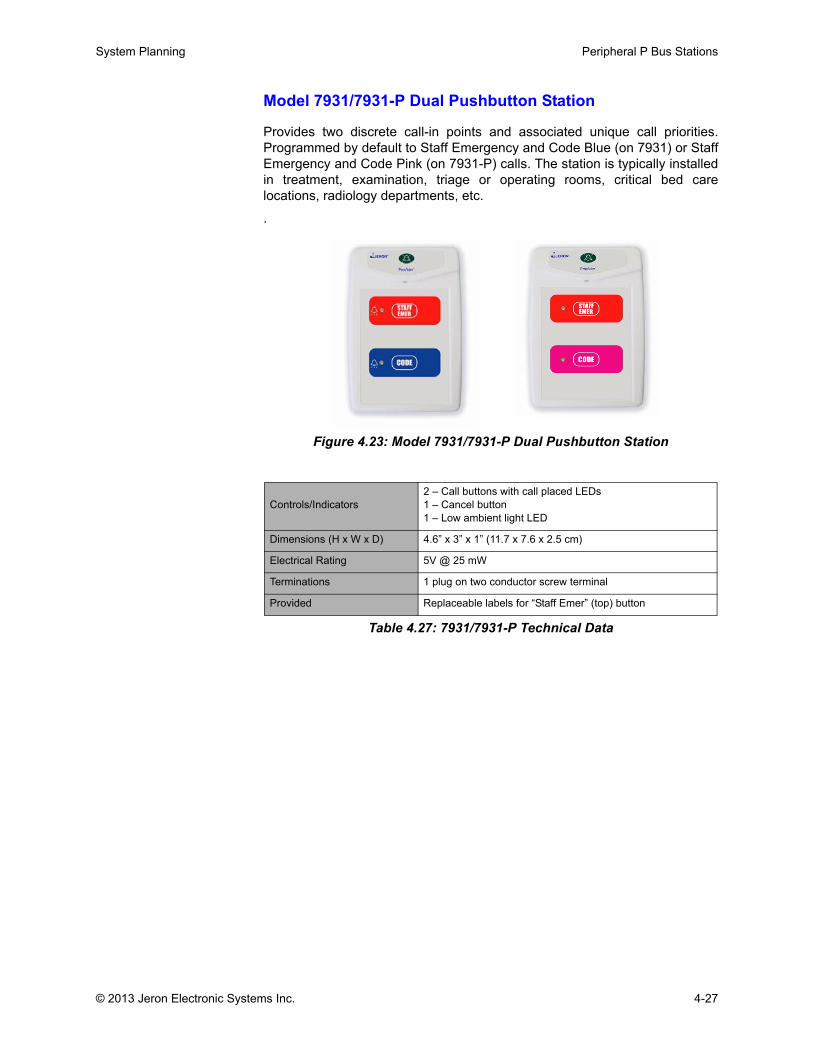
System Planning Peripheral P Bus Stations
Model 7931/7931-P Dual Pushbutton Station
Provides two discrete call-in points and associated unique call priorities.Programmed by default to Staff Emergency and Code Blue (on 7931) or StaffEmergency and Code Pink (on 7931-P) calls. The station is typically installedin treatment, examination, triage or operating rooms, critical bed carelocations, radiology departments, etc.
.
Figure 4.23: Model 7931/7931-P Dual Pushbutton Station
Controls/Indicators2 – Call buttons with call placed LEDs1 – Cancel button1 – Low ambient light LED
Dimensions (H x W x D) 4.6” x 3” x 1” (11.7 x 7.6 x 2.5 cm)
Electrical Rating 5V @ 25 mW
Terminations 1 plug on two conductor screw terminal
Provided Replaceable labels for “Staff Emer” (top) button
Table 4.27: 7931/7931-P Technical Data
© 2013 Jeron Electronic Systems Inc. 4-27
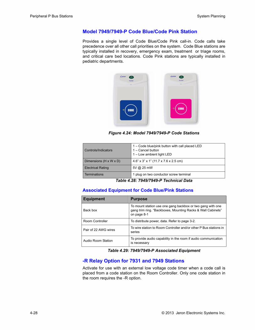
Peripheral P Bus Stations System Planning
Model 7949/7949-P Code Blue/Code Pink Station
Provides a single level of Code Blue/Code Pink call-in. Code calls takeprecedence over all other call priorities on the system. Code Blue stations aretypically installed in recovery, emergency exam, treatment or triage rooms,and critical care bed locations. Code Pink stations are typically installed inpediatric departments.
Figure 4.24: Model 7949/7949-P Code Stations
Table 4.28: 7949/7949-P Technical Data
Associated Equipment for Code Blue/Pink Stations
Table 4.29: 7949/7949-P Associated Equipment
-R Relay Option for 7931 and 7949 StationsActivate for use with an external low voltage code timer when a code call isplaced from a code station on the Room Controller. Only one code station inthe room requires the -R option.
Controls/Indicators1 – Code blue/pink button with call placed LED1 – Cancel button1 – Low ambient light LED
Dimensions (H x W x D) 4.6” x 3” x 1” (11.7 x 7.6 x 2.5 cm)
Electrical Rating 5V @ 25 mW
Terminations 1 plug on two conductor screw terminal
Equipment Purpose
Back boxTo mount station use one gang backbox or two gang with one gang trim ring. “Backboxes, Mounting Racks & Wall Cabinets” on page 8-1
Room Controller To distribute power, data. Refer to page 3-2.
Pair of 22 AWG wires To wire station to Room Controller and/or other P Bus stations in series
Audio Room Station To provide audio capability in the room if audio communication is necessary
4-28 © 2013 Jeron Electronic Systems Inc.
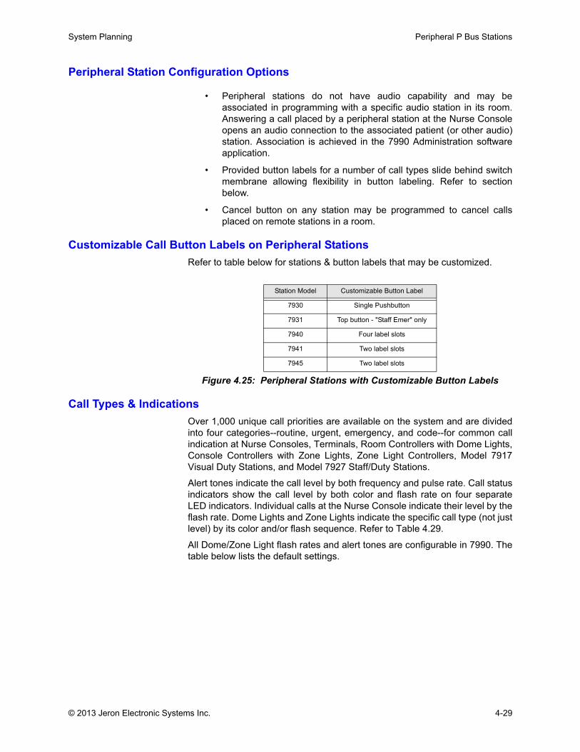
System Planning Peripheral P Bus Stations
Peripheral Station Configuration Options
• Peripheral stations do not have audio capability and may beassociated in programming with a specific audio station in its room.Answering a call placed by a peripheral station at the Nurse Consoleopens an audio connection to the associated patient (or other audio)station. Association is achieved in the 7990 Administration softwareapplication.
• Provided button labels for a number of call types slide behind switchmembrane allowing flexibility in button labeling. Refer to sectionbelow.
• Cancel button on any station may be programmed to cancel callsplaced on remote stations in a room.
Customizable Call Button Labels on Peripheral StationsRefer to table below for stations & button labels that may be customized.
Call Types & Indications Over 1,000 unique call priorities are available on the system and are dividedinto four categories--routine, urgent, emergency, and code--for common callindication at Nurse Consoles, Terminals, Room Controllers with Dome Lights,Console Controllers with Zone Lights, Zone Light Controllers, Model 7917Visual Duty Stations, and Model 7927 Staff/Duty Stations.
Alert tones indicate the call level by both frequency and pulse rate. Call statusindicators show the call level by both color and flash rate on four separateLED indicators. Individual calls at the Nurse Console indicate their level by theflash rate. Dome Lights and Zone Lights indicate the specific call type (not justlevel) by its color and/or flash sequence. Refer to Table 4.29.
All Dome/Zone Light flash rates and alert tones are configurable in 7990. Thetable below lists the default settings.
Station Model Customizable Button Label
7930 Single Pushbutton
7931 Top button - "Staff Emer" only
7940 Four label slots
7941 Two label slots
7945 Two label slots
Figure 4.25: Peripheral Stations with Customizable Button Labels
© 2013 Jeron Electronic Systems Inc. 4-29
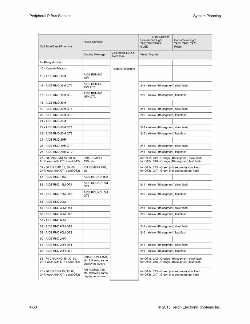
Peripheral P Bus Stations System Planning
Call Type/Event/Priority #Nurse Console
Light Show # Dome/Zone Light7952/7962/79726 LED
Dome/Zone Light7953, 7963, 7973Prism
Display Message Call Status LED & Alert Tone Visual Signals
9 - Relay Access
Status Indicators10 - Remote Privacy
15 - AIDE RMD 15M AIDE REMIND 15M
16 - AIDE RMD 15M OT1 AIDE REMIND 15M OT1 241 - Yellow (4th segment) slow flash
17 - AIDE RMD 15M OT2 AIDE REMIND 15M OT2 245 - Yellow (4th segment) fast flash
18 - AIDE RMD 30M
19 - AIDE RMD 30M OT1 241 - Yellow (4th segment) slow flash
20 - AIDE RMD 30M OT2 245 - Yellow (4th segment) fast flash
21 - AIDE RMD 60M
22 - AIDE RMD 60M OT1 241 - Yellow (4th segment) slow flash
23 - AIDE RMD 60M OT2 245 - Yellow (4th segment) fast flash
24 - AIDE RMD 2HR
25 - AIDE RMD 2HR OT1 241 - Yellow (4th segment) slow flash
26 - AIDE RMD 2HR OT2 245 - Yellow (4th segment) fast flash
27 - 38 CNA RMD 15, 30, 60, 2HR, each with OT1s and OT2s
CNA REMIND 15M, etc.
for OT1s: 242 - Orange (4th segment) slow flashfor OT2s: 246 - Orange (4th segment) fast flash
39 - 50 RN RMD 15, 30, 60, 2HR, each with OT1s and OT2s
RN REMIND 15M, etc.
for OT1s: 243 - Green (4th segment) slow flashfor OT2s: 247 - Green (4th segment) fast flash
51 - AIDE RND 15M AIDE ROUND 15M
52 - AIDE RND 15M OT1 AIDE ROUND 15M OT1 241 - Yellow (4th segment) slow flash
53 - AIDE RND 15M OT2 AIDE ROUND 15M OT2 245 - Yellow (4th segment) fast flash
54 - AIDE RND 30M
55 - AIDE RND 30M OT1 241 - Yellow (4th segment) slow flash
56 - AIDE RND 30M OT2 245 - Yellow (4th segment) fast flash
57 - AIDE RND 60M
58 - AIDE RND 60M OT1 241 - Yellow (4th segment) slow flash
59 - AIDE RND 60M OT2 245 - Yellow (4th segment) fast flash
60 - AIDE RND 2HR
61 - AIDE RND 2HR OT1 241 - Yellow (4th segment) slow flash
62 - AIDE RND 2HR OT2 245 - Yellow (4th segment) fast flash
63 - 74 CNA RND 15, 30, 60, 2HR, each with OT1s and OT2s
CNA ROUND 15M, etc. following same display as above
for OT1s: 242 - Orange (4th segment) slow flashfor OT2s: 246 - Orange (4th segment) fast flash
75 - 86 RN RND 15, 30, 60, 2HR, each with OT1s and OT2s
RN ROUND 15M, etc. following same display as above
for OT1s: 243 - Green (4th segment) slow flashfor OT2s: 247 - Green (4th segment) fast flash
4-30 © 2013 Jeron Electronic Systems Inc.
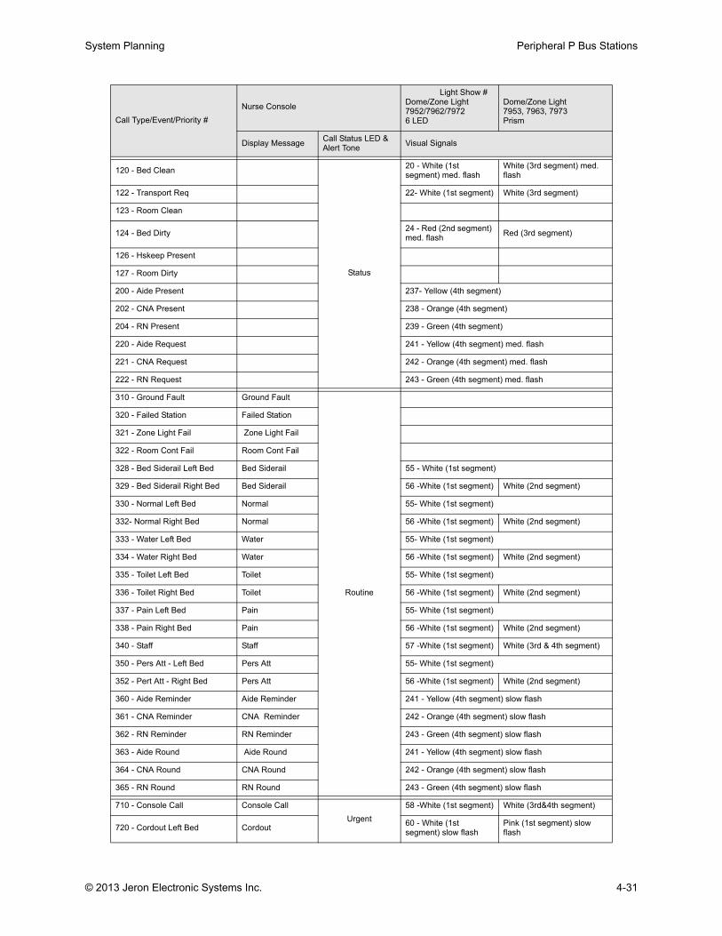
System Planning Peripheral P Bus Stations
120 - Bed Clean
Status
20 - White (1st segment) med. flash
White (3rd segment) med. flash
122 - Transport Req 22- White (1st segment) White (3rd segment)
123 - Room Clean
124 - Bed Dirty 24 - Red (2nd segment) med. flash Red (3rd segment)
126 - Hskeep Present
127 - Room Dirty
200 - Aide Present 237- Yellow (4th segment)
202 - CNA Present 238 - Orange (4th segment)
204 - RN Present 239 - Green (4th segment)
220 - Aide Request 241 - Yellow (4th segment) med. flash
221 - CNA Request 242 - Orange (4th segment) med. flash
222 - RN Request 243 - Green (4th segment) med. flash
310 - Ground Fault Ground Fault
Routine
320 - Failed Station Failed Station
321 - Zone Light Fail Zone Light Fail
322 - Room Cont Fail Room Cont Fail
328 - Bed Siderail Left Bed Bed Siderail 55 - White (1st segment)
329 - Bed Siderail Right Bed Bed Siderail 56 -White (1st segment) White (2nd segment)
330 - Normal Left Bed Normal 55- White (1st segment)
332- Normal Right Bed Normal 56 -White (1st segment) White (2nd segment)
333 - Water Left Bed Water 55- White (1st segment)
334 - Water Right Bed Water 56 -White (1st segment) White (2nd segment)
335 - Toilet Left Bed Toilet 55- White (1st segment)
336 - Toilet Right Bed Toilet 56 -White (1st segment) White (2nd segment)
337 - Pain Left Bed Pain 55- White (1st segment)
338 - Pain Right Bed Pain 56 -White (1st segment) White (2nd segment)
340 - Staff Staff 57 -White (1st segment) White (3rd & 4th segment)
350 - Pers Att - Left Bed Pers Att 55- White (1st segment)
352 - Pert Att - Right Bed Pers Att 56 -White (1st segment) White (2nd segment)
360 - Aide Reminder Aide Reminder 241 - Yellow (4th segment) slow flash
361 - CNA Reminder CNA Reminder 242 - Orange (4th segment) slow flash
362 - RN Reminder RN Reminder 243 - Green (4th segment) slow flash
363 - Aide Round Aide Round 241 - Yellow (4th segment) slow flash
364 - CNA Round CNA Round 242 - Orange (4th segment) slow flash
365 - RN Round RN Round 243 - Green (4th segment) slow flash
710 - Console Call Console CallUrgent
58 -White (1st segment) White (3rd&4th segment)
720 - Cordout Left Bed Cordout 60 - White (1st segment) slow flash
Pink (1st segment) slow flash
Call Type/Event/Priority #Nurse Console
Light Show # Dome/Zone Light7952/7962/79726 LED
Dome/Zone Light7953, 7963, 7973Prism
Display Message Call Status LED & Alert Tone Visual Signals
© 2013 Jeron Electronic Systems Inc. 4-31
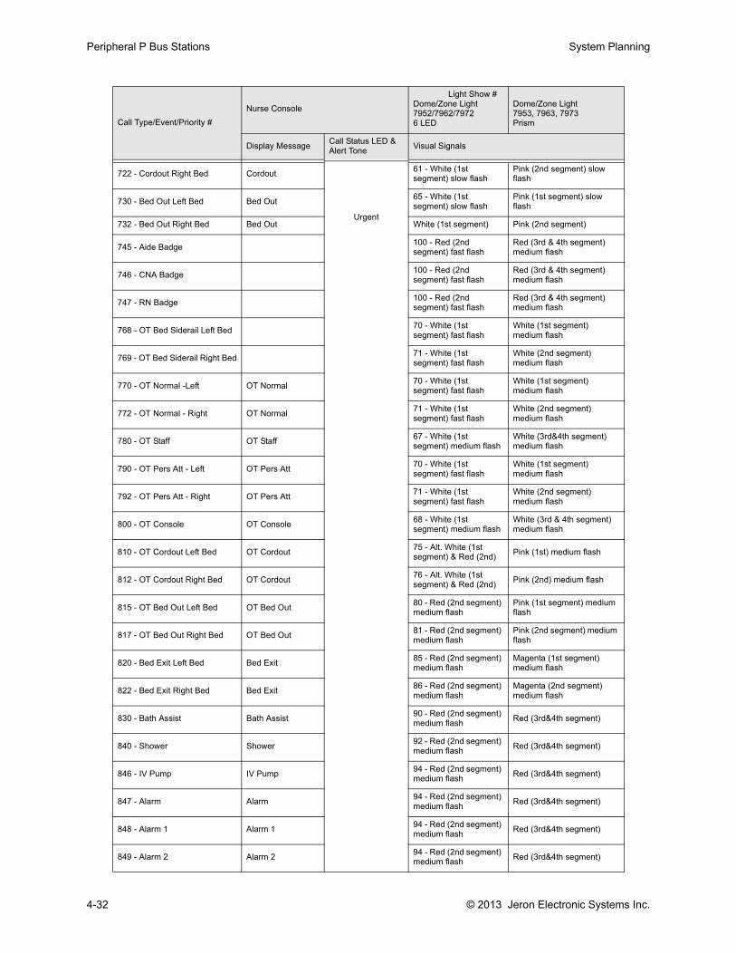
Peripheral P Bus Stations System Planning
722 - Cordout Right Bed Cordout
Urgent
61 - White (1st segment) slow flash
Pink (2nd segment) slow flash
730 - Bed Out Left Bed Bed Out 65 - White (1st segment) slow flash
Pink (1st segment) slow flash
732 - Bed Out Right Bed Bed Out White (1st segment) Pink (2nd segment)
745 - Aide Badge 100 - Red (2nd segment) fast flash
Red (3rd & 4th segment) medium flash
746 - CNA Badge 100 - Red (2nd segment) fast flash
Red (3rd & 4th segment) medium flash
747 - RN Badge 100 - Red (2nd segment) fast flash
Red (3rd & 4th segment) medium flash
768 - OT Bed Siderail Left Bed 70 - White (1st segment) fast flash
White (1st segment) medium flash
769 - OT Bed Siderail Right Bed 71 - White (1st segment) fast flash
White (2nd segment) medium flash
770 - OT Normal -Left OT Normal 70 - White (1st segment) fast flash
White (1st segment) medium flash
772 - OT Normal - Right OT Normal 71 - White (1st segment) fast flash
White (2nd segment) medium flash
780 - OT Staff OT Staff 67 - White (1st segment) medium flash
White (3rd&4th segment) medium flash
790 - OT Pers Att - Left OT Pers Att 70 - White (1st segment) fast flash
White (1st segment) medium flash
792 - OT Pers Att - Right OT Pers Att 71 - White (1st segment) fast flash
White (2nd segment) medium flash
800 - OT Console OT Console 68 - White (1st segment) medium flash
White (3rd & 4th segment) medium flash
810 - OT Cordout Left Bed OT Cordout 75 - Alt. White (1st segment) & Red (2nd) Pink (1st) medium flash
812 - OT Cordout Right Bed OT Cordout 76 - Alt. White (1st segment) & Red (2nd) Pink (2nd) medium flash
815 - OT Bed Out Left Bed OT Bed Out 80 - Red (2nd segment) medium flash
Pink (1st segment) medium flash
817 - OT Bed Out Right Bed OT Bed Out 81 - Red (2nd segment) medium flash
Pink (2nd segment) medium flash
820 - Bed Exit Left Bed Bed Exit 85 - Red (2nd segment) medium flash
Magenta (1st segment) medium flash
822 - Bed Exit Right Bed Bed Exit 86 - Red (2nd segment) medium flash
Magenta (2nd segment) medium flash
830 - Bath Assist Bath Assist 90 - Red (2nd segment) medium flash Red (3rd&4th segment)
840 - Shower Shower 92 - Red (2nd segment) medium flash Red (3rd&4th segment)
846 - IV Pump IV Pump 94 - Red (2nd segment) medium flash Red (3rd&4th segment)
847 - Alarm Alarm 94 - Red (2nd segment) medium flash Red (3rd&4th segment)
848 - Alarm 1 Alarm 1 94 - Red (2nd segment) medium flash Red (3rd&4th segment)
849 - Alarm 2 Alarm 2 94 - Red (2nd segment) medium flash Red (3rd&4th segment)
Call Type/Event/Priority #Nurse Console
Light Show # Dome/Zone Light7952/7962/79726 LED
Dome/Zone Light7953, 7963, 7973Prism
Display Message Call Status LED & Alert Tone Visual Signals
4-32 © 2013 Jeron Electronic Systems Inc.
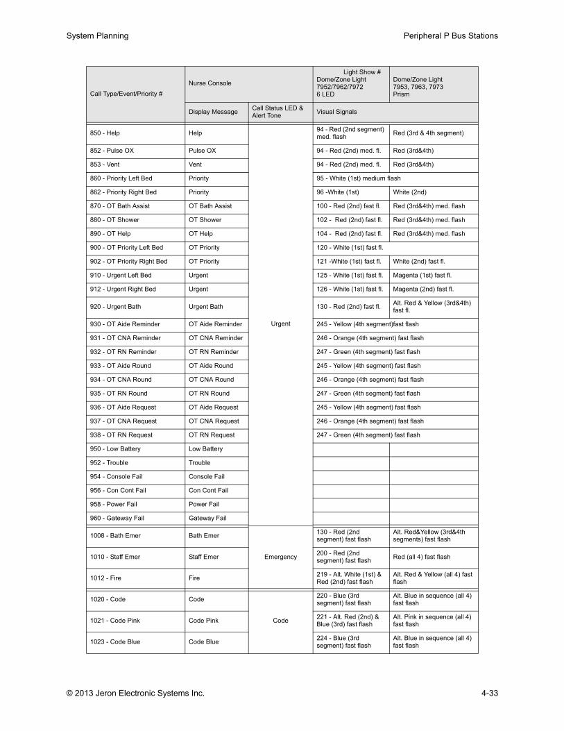
System Planning Peripheral P Bus Stations
850 - Help Help
Urgent
94 - Red (2nd segment) med. flash Red (3rd & 4th segment)
852 - Pulse OX Pulse OX 94 - Red (2nd) med. fl. Red (3rd&4th)
853 - Vent Vent 94 - Red (2nd) med. fl. Red (3rd&4th)
860 - Priority Left Bed Priority 95 - White (1st) medium flash
862 - Priority Right Bed Priority 96 -White (1st) White (2nd)
870 - OT Bath Assist OT Bath Assist 100 - Red (2nd) fast fl. Red (3rd&4th) med. flash
880 - OT Shower OT Shower 102 - Red (2nd) fast fl. Red (3rd&4th) med. flash
890 - OT Help OT Help 104 - Red (2nd) fast fl. Red (3rd&4th) med. flash
900 - OT Priority Left Bed OT Priority 120 - White (1st) fast fl.
902 - OT Priority Right Bed OT Priority 121 -White (1st) fast fl. White (2nd) fast fl.
910 - Urgent Left Bed Urgent 125 - White (1st) fast fl. Magenta (1st) fast fl.
912 - Urgent Right Bed Urgent 126 - White (1st) fast fl. Magenta (2nd) fast fl.
920 - Urgent Bath Urgent Bath 130 - Red (2nd) fast fl. Alt. Red & Yellow (3rd&4th) fast fl.
930 - OT Aide Reminder OT Aide Reminder 245 - Yellow (4th segment)fast flash
931 - OT CNA Reminder OT CNA Reminder 246 - Orange (4th segment) fast flash
932 - OT RN Reminder OT RN Reminder 247 - Green (4th segment) fast flash
933 - OT Aide Round OT Aide Round 245 - Yellow (4th segment) fast flash
934 - OT CNA Round OT CNA Round 246 - Orange (4th segment) fast flash
935 - OT RN Round OT RN Round 247 - Green (4th segment) fast flash
936 - OT Aide Request OT Aide Request 245 - Yellow (4th segment) fast flash
937 - OT CNA Request OT CNA Request 246 - Orange (4th segment) fast flash
938 - OT RN Request OT RN Request 247 - Green (4th segment) fast flash
950 - Low Battery Low Battery
952 - Trouble Trouble
954 - Console Fail Console Fail
956 - Con Cont Fail Con Cont Fail
958 - Power Fail Power Fail
960 - Gateway Fail Gateway Fail
1008 - Bath Emer Bath Emer
Emergency
130 - Red (2nd segment) fast flash
Alt. Red&Yellow (3rd&4th segments) fast flash
1010 - Staff Emer Staff Emer 200 - Red (2nd segment) fast flash Red (all 4) fast flash
1012 - Fire Fire 219 - Alt. White (1st) & Red (2nd) fast flash
Alt. Red & Yellow (all 4) fast flash
1020 - Code Code
Code
220 - Blue (3rd segment) fast flash
Alt. Blue in sequence (all 4) fast flash
1021 - Code Pink Code Pink 221 - Alt. Red (2nd) & Blue (3rd) fast flash
Alt. Pink in sequence (all 4) fast flash
1023 - Code Blue Code Blue 224 - Blue (3rd segment) fast flash
Alt. Blue in sequence (all 4) fast flash
Call Type/Event/Priority #Nurse Console
Light Show # Dome/Zone Light7952/7962/79726 LED
Dome/Zone Light7953, 7963, 7973Prism
Display Message Call Status LED & Alert Tone Visual Signals
© 2013 Jeron Electronic Systems Inc. 4-33
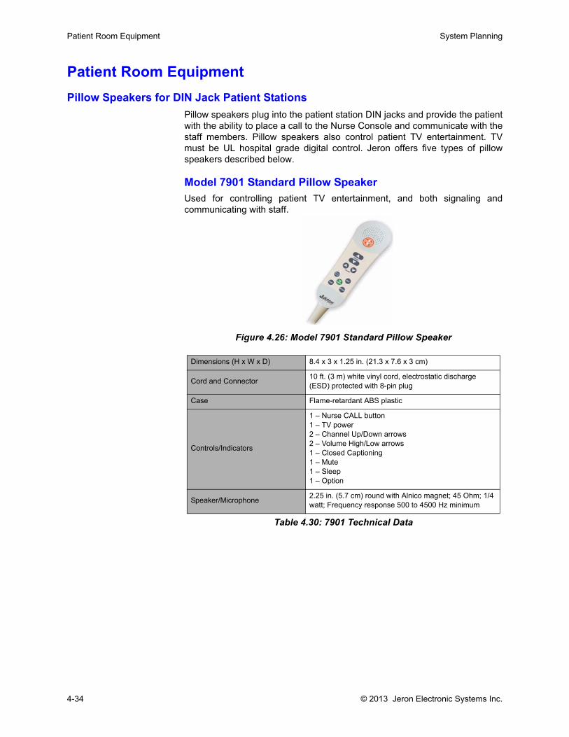
Patient Room Equipment System Planning
Patient Room EquipmentPillow Speakers for DIN Jack Patient Stations
Pillow speakers plug into the patient station DIN jacks and provide the patientwith the ability to place a call to the Nurse Console and communicate with thestaff members. Pillow speakers also control patient TV entertainment. TVmust be UL hospital grade digital control. Jeron offers five types of pillowspeakers described below.
Model 7901 Standard Pillow SpeakerUsed for controlling patient TV entertainment, and both signaling andcommunicating with staff.
Figure 4.26: Model 7901 Standard Pillow Speaker
Dimensions (H x W x D) 8.4 x 3 x 1.25 in. (21.3 x 7.6 x 3 cm)
Cord and Connector 10 ft. (3 m) white vinyl cord, electrostatic discharge (ESD) protected with 8-pin plug
Case Flame-retardant ABS plastic
Controls/Indicators
1 – Nurse CALL button1 – TV power2 – Channel Up/Down arrows2 – Volume High/Low arrows1 – Closed Captioning1 – Mute1 – Sleep1 – Option
Speaker/Microphone 2.25 in. (5.7 cm) round with Alnico magnet; 45 Ohm; 1/4 watt; Frequency response 500 to 4500 Hz minimum
Table 4.30: 7901 Technical Data
4-34 © 2013 Jeron Electronic Systems Inc.
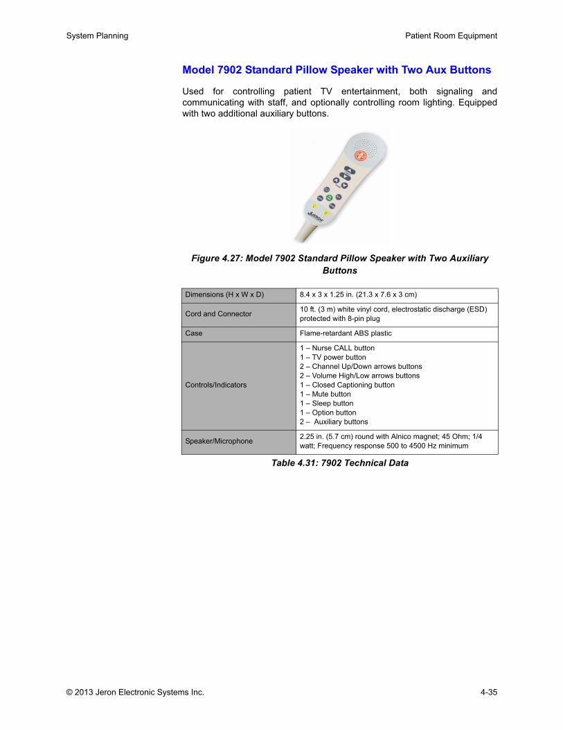
System Planning Patient Room Equipment
Model 7902 Standard Pillow Speaker with Two Aux Buttons
Used for controlling patient TV entertainment, both signaling andcommunicating with staff, and optionally controlling room lighting. Equippedwith two additional auxiliary buttons.
Figure 4.27: Model 7902 Standard Pillow Speaker with Two Auxiliary Buttons
Dimensions (H x W x D) 8.4 x 3 x 1.25 in. (21.3 x 7.6 x 3 cm)
Cord and Connector 10 ft. (3 m) white vinyl cord, electrostatic discharge (ESD) protected with 8-pin plug
Case Flame-retardant ABS plastic
Controls/Indicators
1 – Nurse CALL button1 – TV power button2 – Channel Up/Down arrows buttons2 – Volume High/Low arrows buttons1 – Closed Captioning button1 – Mute button1 – Sleep button1 – Option button2 – Auxiliary buttons
Speaker/Microphone 2.25 in. (5.7 cm) round with Alnico magnet; 45 Ohm; 1/4 watt; Frequency response 500 to 4500 Hz minimum
Table 4.31: 7902 Technical Data
© 2013 Jeron Electronic Systems Inc. 4-35
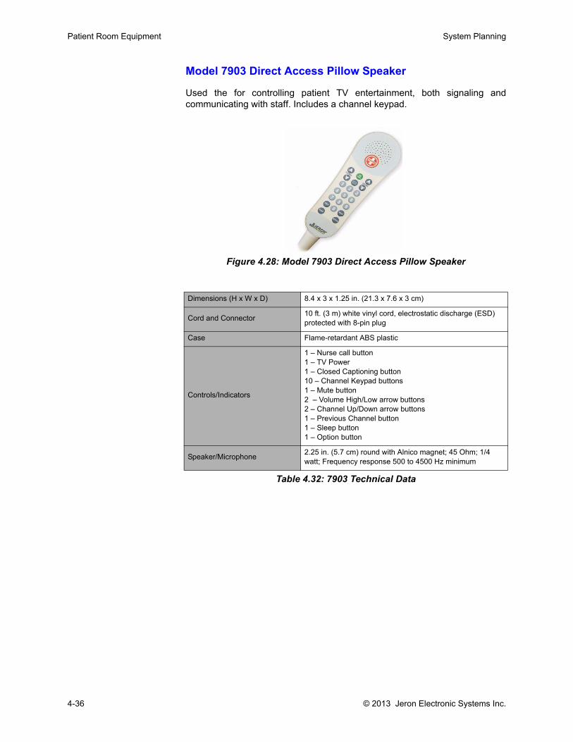
Patient Room Equipment System Planning
Model 7903 Direct Access Pillow Speaker
Used the for controlling patient TV entertainment, both signaling andcommunicating with staff. Includes a channel keypad.
Figure 4.28: Model 7903 Direct Access Pillow Speaker
Dimensions (H x W x D) 8.4 x 3 x 1.25 in. (21.3 x 7.6 x 3 cm)
Cord and Connector 10 ft. (3 m) white vinyl cord, electrostatic discharge (ESD) protected with 8-pin plug
Case Flame-retardant ABS plastic
Controls/Indicators
1 – Nurse call button1 – TV Power1 – Closed Captioning button10 – Channel Keypad buttons1 – Mute button2 – Volume High/Low arrow buttons2 – Channel Up/Down arrow buttons1 – Previous Channel button1 – Sleep button1 – Option button
Speaker/Microphone 2.25 in. (5.7 cm) round with Alnico magnet; 45 Ohm; 1/4 watt; Frequency response 500 to 4500 Hz minimum
Table 4.32: 7903 Technical Data
4-36 © 2013 Jeron Electronic Systems Inc.
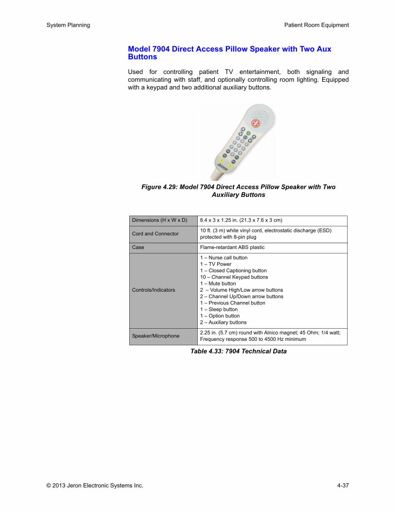
System Planning Patient Room Equipment
Model 7904 Direct Access Pillow Speaker with Two Aux Buttons
Used for controlling patient TV entertainment, both signaling andcommunicating with staff, and optionally controlling room lighting. Equippedwith a keypad and two additional auxiliary buttons.
Figure 4.29: Model 7904 Direct Access Pillow Speaker with Two Auxiliary Buttons
Dimensions (H x W x D) 8.4 x 3 x 1.25 in. (21.3 x 7.6 x 3 cm)
Cord and Connector 10 ft. (3 m) white vinyl cord, electrostatic discharge (ESD) protected with 8-pin plug
Case Flame-retardant ABS plastic
Controls/Indicators
1 – Nurse call button1 – TV Power1 – Closed Captioning button10 – Channel Keypad buttons1 – Mute button2 – Volume High/Low arrow buttons2 – Channel Up/Down arrow buttons1 – Previous Channel button1 – Sleep button1 – Option button2 – Auxiliary buttons
Speaker/Microphone 2.25 in. (5.7 cm) round with Alnico magnet; 45 Ohm; 1/4 watt; Frequency response 500 to 4500 Hz minimum
Table 4.33: 7904 Technical Data
© 2013 Jeron Electronic Systems Inc. 4-37
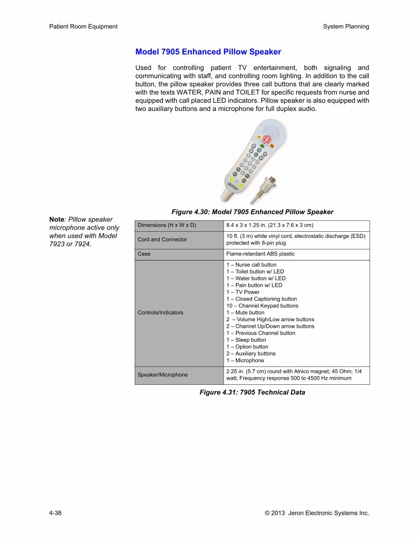
Patient Room Equipment System Planning
Model 7905 Enhanced Pillow Speaker
Used for controlling patient TV entertainment, both signaling andcommunicating with staff, and controlling room lighting. In addition to the callbutton, the pillow speaker provides three call buttons that are clearly markedwith the texts WATER, PAIN and TOILET for specific requests from nurse andequipped with call placed LED indicators. Pillow speaker is also equipped withtwo auxiliary buttons and a microphone for full duplex audio.
Figure 4.30: Model 7905 Enhanced Pillow Speaker
Figure 4.31: 7905 Technical Data
Dimensions (H x W x D) 8.4 x 3 x 1.25 in. (21.3 x 7.6 x 3 cm)
Cord and Connector 10 ft. (3 m) white vinyl cord, electrostatic discharge (ESD) protected with 8-pin plug
Case Flame-retardant ABS plastic
Controls/Indicators
1 – Nurse call button1 – Toilet button w/ LED1 – Water button w/ LED1 – Pain button w/ LED1 – TV Power1 – Closed Captioning button10 – Channel Keypad buttons1 – Mute button2 – Volume High/Low arrow buttons2 – Channel Up/Down arrow buttons1 – Previous Channel button1 – Sleep button1 – Option button2 – Auxiliary buttons1 – Microphone
Speaker/Microphone 2.25 in. (5.7 cm) round with Alnico magnet; 45 Ohm; 1/4 watt; Frequency response 500 to 4500 Hz minimum
Note: Pillow speaker microphone active only when used with Model 7923 or 7924.
4-38 © 2013 Jeron Electronic Systems Inc.
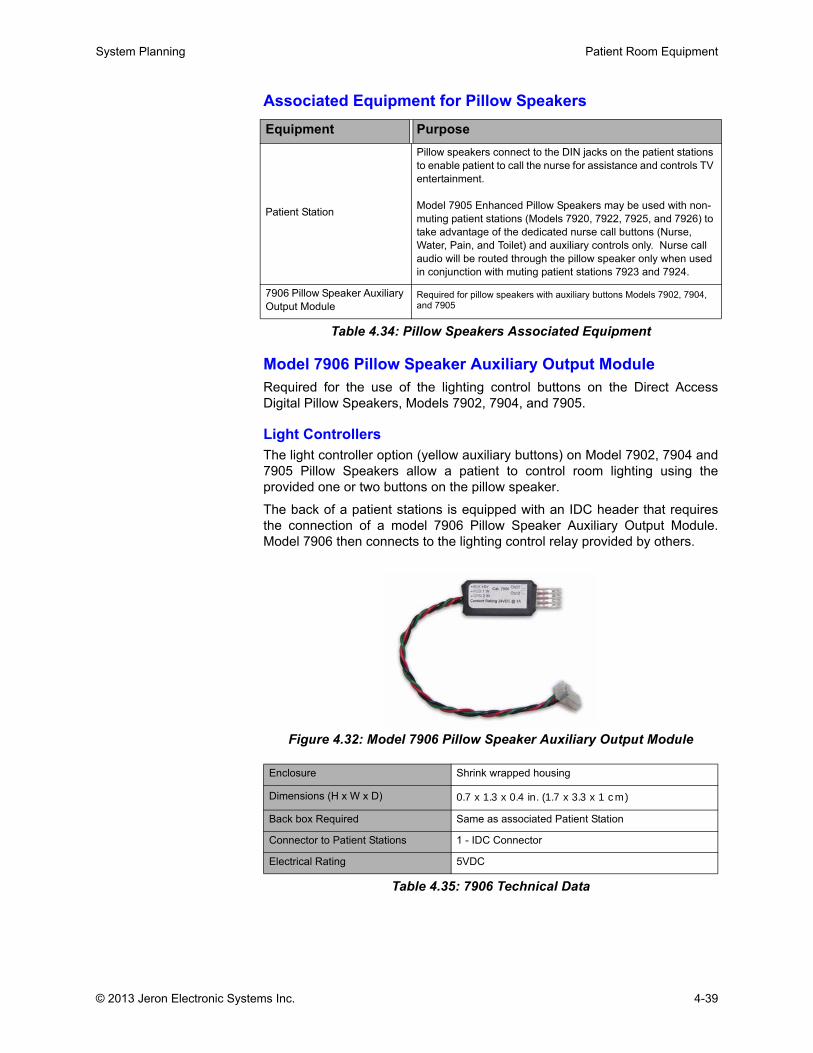
System Planning Patient Room Equipment
Associated Equipment for Pillow Speakers
Table 4.34: Pillow Speakers Associated Equipment
Model 7906 Pillow Speaker Auxiliary Output ModuleRequired for the use of the lighting control buttons on the Direct AccessDigital Pillow Speakers, Models 7902, 7904, and 7905.
Light Controllers The light controller option (yellow auxiliary buttons) on Model 7902, 7904 and7905 Pillow Speakers allow a patient to control room lighting using theprovided one or two buttons on the pillow speaker.
The back of a patient stations is equipped with an IDC header that requiresthe connection of a model 7906 Pillow Speaker Auxiliary Output Module.Model 7906 then connects to the lighting control relay provided by others.
Figure 4.32: Model 7906 Pillow Speaker Auxiliary Output Module
Equipment Purpose
Patient Station
Pillow speakers connect to the DIN jacks on the patient stations to enable patient to call the nurse for assistance and controls TV entertainment.
Model 7905 Enhanced Pillow Speakers may be used with non-muting patient stations (Models 7920, 7922, 7925, and 7926) to take advantage of the dedicated nurse call buttons (Nurse, Water, Pain, and Toilet) and auxiliary controls only. Nurse call audio will be routed through the pillow speaker only when used in conjunction with muting patient stations 7923 and 7924.
7906 Pillow Speaker Auxiliary Output Module
Required for pillow speakers with auxiliary buttons Models 7902, 7904, and 7905
Enclosure Shrink wrapped housing
Dimensions (H x W x D) 0.7 x 1.3 x 0.4 in. (1.7 x 3.3 x 1 cm)
Back box Required Same as associated Patient Station
Connector to Patient Stations 1 - IDC Connector
Electrical Rating 5VDC
Table 4.35: 7906 Technical Data
© 2013 Jeron Electronic Systems Inc. 4-39
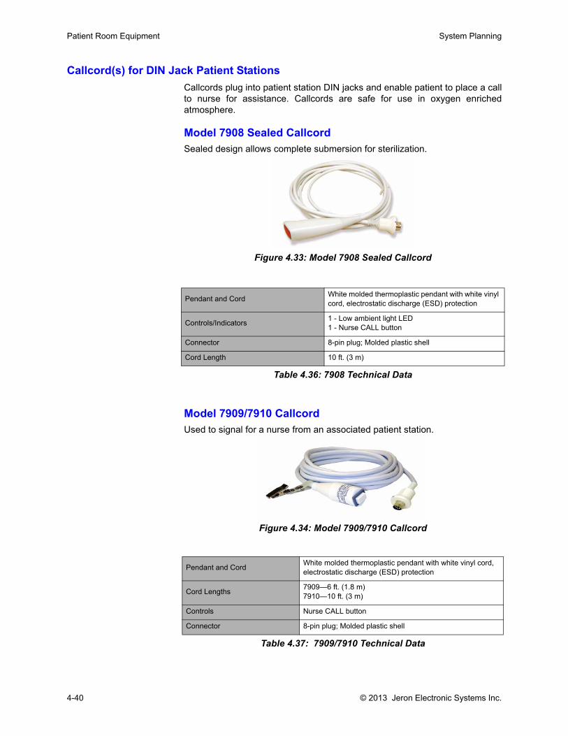
Patient Room Equipment System Planning
Callcord(s) for DIN Jack Patient StationsCallcords plug into patient station DIN jacks and enable patient to place a callto nurse for assistance. Callcords are safe for use in oxygen enrichedatmosphere.
Model 7908 Sealed CallcordSealed design allows complete submersion for sterilization.
Figure 4.33: Model 7908 Sealed Callcord
Model 7909/7910 CallcordUsed to signal for a nurse from an associated patient station.
Figure 4.34: Model 7909/7910 Callcord
Pendant and Cord White molded thermoplastic pendant with white vinyl cord, electrostatic discharge (ESD) protection
Controls/Indicators 1 - Low ambient light LED1 - Nurse CALL button
Connector 8-pin plug; Molded plastic shell
Cord Length 10 ft. (3 m)
Table 4.36: 7908 Technical Data
Pendant and Cord White molded thermoplastic pendant with white vinyl cord, electrostatic discharge (ESD) protection
Cord Lengths 7909—6 ft. (1.8 m)7910—10 ft. (3 m)
Controls Nurse CALL button
Connector 8-pin plug; Molded plastic shell
Table 4.37: 7909/7910 Technical Data
4-40 © 2013 Jeron Electronic Systems Inc.

System Planning Patient Room Equipment
Model 7913 Callcord Adapter, 1/4”-to-DINUsed to connect third party callcord devices to patient stations DIN jack.
Figure 4.35: Model 7913 Callcord Adapter
Model 7914 Geriatric Callcord
Provide a means of signaling for assistance with only slight hand or bodypressure. Geriatric Callcords are used in hospitals and nursing homes forgeriatric or pediatric patients, for feeble or disabled patients, for completesafety in an oxygen-enriched environment, or for use in showers.
Figure 4.36: Model 7914 Geriatric Callcord
Model 8839 Breath Activated Callcord
Provide a means of signaling for assistance by fully disabled patients whocannot operate a conventional callcord by pressing a button or squeezing abulb. Breath Activated Callcords offer complete safety in an oxygen-enrichedenvironment.
Requires use of 7913 Callcord Adapter to convert 1/4” jack into a DIN jack.
Connections 8-pin DIN to 1/4” call jack
Table 4.38: 7913 Technical Data
Bulb & Cord 6 ft. (1.8 m) Gray non-toxic tubing with matching molded air bulb
Controls Air Bulb; pressure activated
Connector 8-pin plug; molded plastic shell
Table 4.39: 7914 Technical Data
© 2013 Jeron Electronic Systems Inc. 4-41
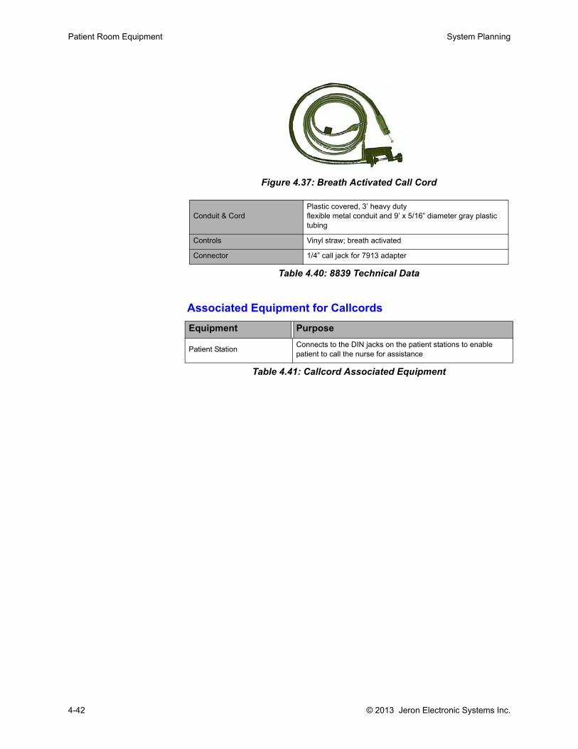
Patient Room Equipment System Planning
Figure 4.37: Breath Activated Call Cord
Associated Equipment for Callcords
Table 4.41: Callcord Associated Equipment
Conduit & Cord Plastic covered, 3’ heavy dutyflexible metal conduit and 9’ x 5/16” diameter gray plastic tubing
Controls Vinyl straw; breath activated
Connector 1/4” call jack for 7913 adapter
Table 4.40: 8839 Technical Data
Equipment Purpose
Patient Station Connects to the DIN jacks on the patient stations to enable patient to call the nurse for assistance
4-42 © 2013 Jeron Electronic Systems Inc.

Chapter 5: Consoles & Terminals

.
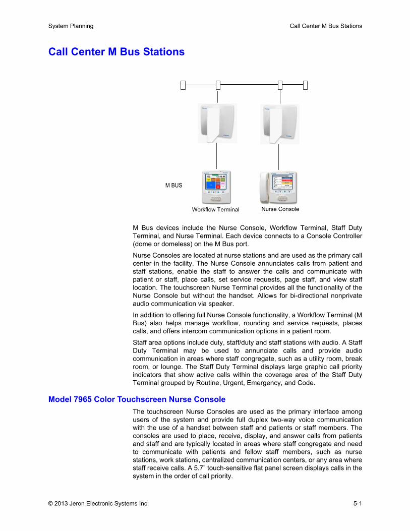
System Planning Call Center M Bus Stations
Call Center M Bus Stations
M Bus devices include the Nurse Console, Workflow Terminal, Staff DutyTerminal, and Nurse Terminal. Each device connects to a Console Controller(dome or domeless) on the M Bus port.
Nurse Consoles are located at nurse stations and are used as the primary callcenter in the facility. The Nurse Console annunciates calls from patient andstaff stations, enable the staff to answer the calls and communicate withpatient or staff, place calls, set service requests, page staff, and view stafflocation. The touchscreen Nurse Terminal provides all the functionality of theNurse Console but without the handset. Allows for bi-directional nonprivateaudio communication via speaker.
In addition to offering full Nurse Console functionality, a Workflow Terminal (MBus) also helps manage workflow, rounding and service requests, placescalls, and offers intercom communication options in a patient room.
Staff area options include duty, staff/duty and staff stations with audio. A StaffDuty Terminal may be used to annunciate calls and provide audiocommunication in areas where staff congregate, such as a utility room, breakroom, or lounge. The Staff Duty Terminal displays large graphic call priorityindicators that show active calls within the coverage area of the Staff DutyTerminal grouped by Routine, Urgent, Emergency, and Code.
Model 7965 Color Touchscreen Nurse ConsoleThe touchscreen Nurse Consoles are used as the primary interface amongusers of the system and provide full duplex two-way voice communicationwith the use of a handset between staff and patients or staff members. Theconsoles are used to place, receive, display, and answer calls from patientsand staff and are typically located in areas where staff congregate and needto communicate with patients and fellow staff members, such as nursestations, work stations, centralized communication centers, or any area wherestaff receive calls. A 5.7” touch-sensitive flat panel screen displays calls in thesystem in the order of call priority.
M BUS
Nurse ConsoleWorkflow Terminal
© 2013 Jeron Electronic Systems Inc. 5-1
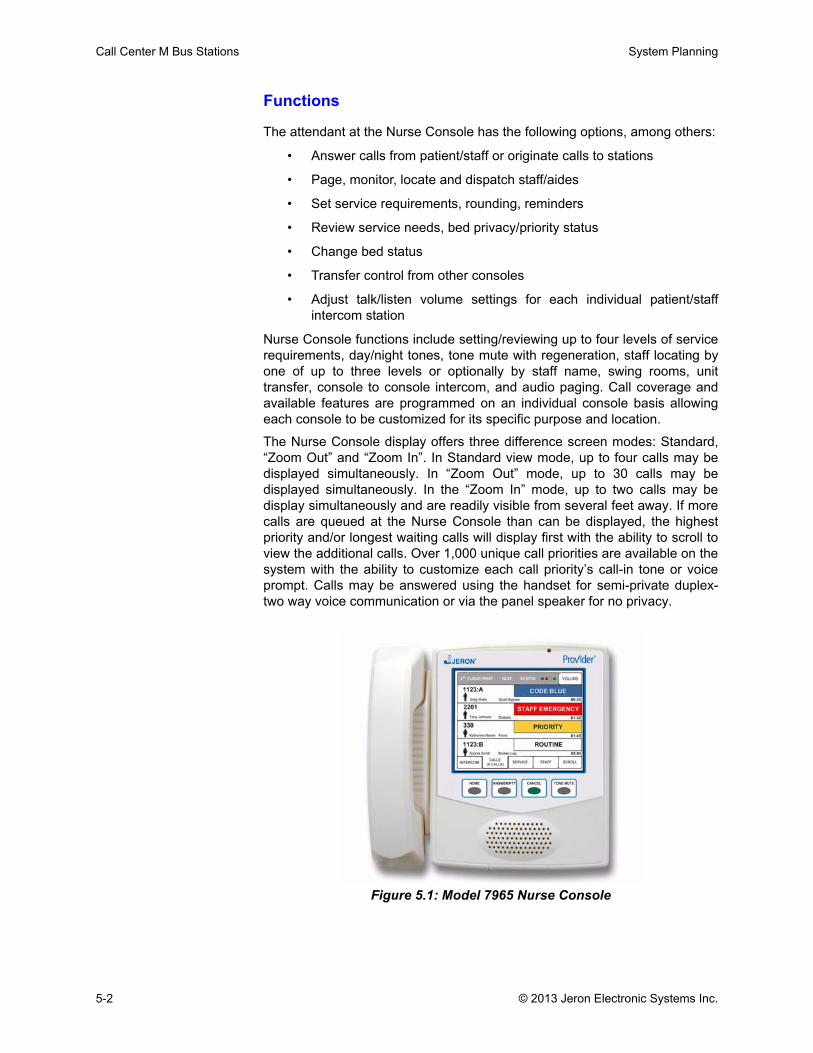
Call Center M Bus Stations System Planning
Functions
The attendant at the Nurse Console has the following options, among others:
• Answer calls from patient/staff or originate calls to stations
• Page, monitor, locate and dispatch staff/aides
• Set service requirements, rounding, reminders
• Review service needs, bed privacy/priority status
• Change bed status
• Transfer control from other consoles
• Adjust talk/listen volume settings for each individual patient/staffintercom station
Nurse Console functions include setting/reviewing up to four levels of servicerequirements, day/night tones, tone mute with regeneration, staff locating byone of up to three levels or optionally by staff name, swing rooms, unittransfer, console to console intercom, and audio paging. Call coverage andavailable features are programmed on an individual console basis allowingeach console to be customized for its specific purpose and location.
The Nurse Console display offers three difference screen modes: Standard,“Zoom Out” and “Zoom In”. In Standard view mode, up to four calls may bedisplayed simultaneously. In “Zoom Out” mode, up to 30 calls may bedisplayed simultaneously. In the “Zoom In” mode, up to two calls may bedisplay simultaneously and are readily visible from several feet away. If morecalls are queued at the Nurse Console than can be displayed, the highestpriority and/or longest waiting calls will display first with the ability to scroll toview the additional calls. Over 1,000 unique call priorities are available on thesystem with the ability to customize each call priority’s call-in tone or voiceprompt. Calls may be answered using the handset for semi-private duplex-two way voice communication or via the panel speaker for no privacy.
Figure 5.1: Model 7965 Nurse Console
5-2 © 2013 Jeron Electronic Systems Inc.
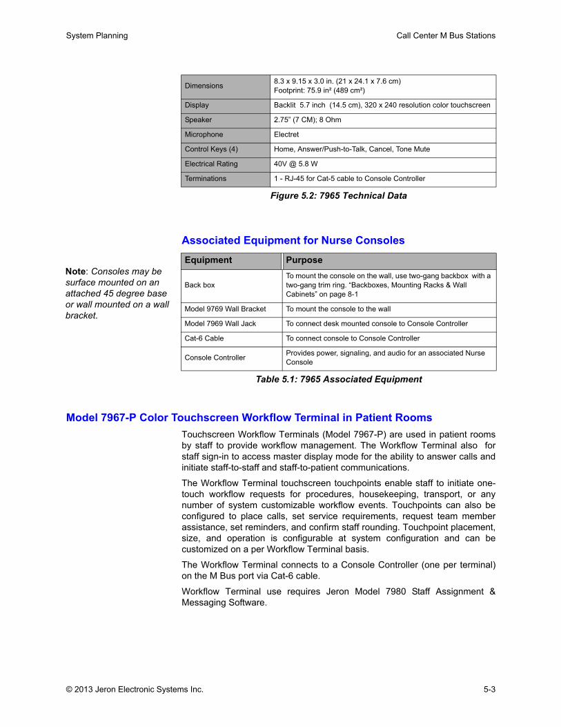
System Planning Call Center M Bus Stations
Figure 5.2: 7965 Technical Data
Associated Equipment for Nurse Consoles
Table 5.1: 7965 Associated Equipment
Model 7967-P Color Touchscreen Workflow Terminal in Patient RoomsTouchscreen Workflow Terminals (Model 7967-P) are used in patient roomsby staff to provide workflow management. The Workflow Terminal also forstaff sign-in to access master display mode for the ability to answer calls andinitiate staff-to-staff and staff-to-patient communications.
The Workflow Terminal touchscreen touchpoints enable staff to initiate one-touch workflow requests for procedures, housekeeping, transport, or anynumber of system customizable workflow events. Touchpoints can also beconfigured to place calls, set service requirements, request team memberassistance, set reminders, and confirm staff rounding. Touchpoint placement,size, and operation is configurable at system configuration and can becustomized on a per Workflow Terminal basis.
The Workflow Terminal connects to a Console Controller (one per terminal)on the M Bus port via Cat-6 cable.
Workflow Terminal use requires Jeron Model 7980 Staff Assignment &Messaging Software.
Dimensions 8.3 x 9.15 x 3.0 in. (21 x 24.1 x 7.6 cm)Footprint: 75.9 in² (489 cm²)
Display Backlit 5.7 inch (14.5 cm), 320 x 240 resolution color touchscreen
Speaker 2.75” (7 CM); 8 Ohm
Microphone Electret
Control Keys (4) Home, Answer/Push-to-Talk, Cancel, Tone Mute
Electrical Rating 40V @ 5.8 W
Terminations 1 - RJ-45 for Cat-5 cable to Console Controller
Equipment Purpose
Back boxTo mount the console on the wall, use two-gang backbox with a two-gang trim ring. “Backboxes, Mounting Racks & Wall Cabinets” on page 8-1
Model 9769 Wall Bracket To mount the console to the wall
Model 7969 Wall Jack To connect desk mounted console to Console Controller
Cat-6 Cable To connect console to Console Controller
Console Controller Provides power, signaling, and audio for an associated Nurse Console
Note: Consoles may be surface mounted on an attached 45 degree base or wall mounted on a wall bracket.
© 2013 Jeron Electronic Systems Inc. 5-3
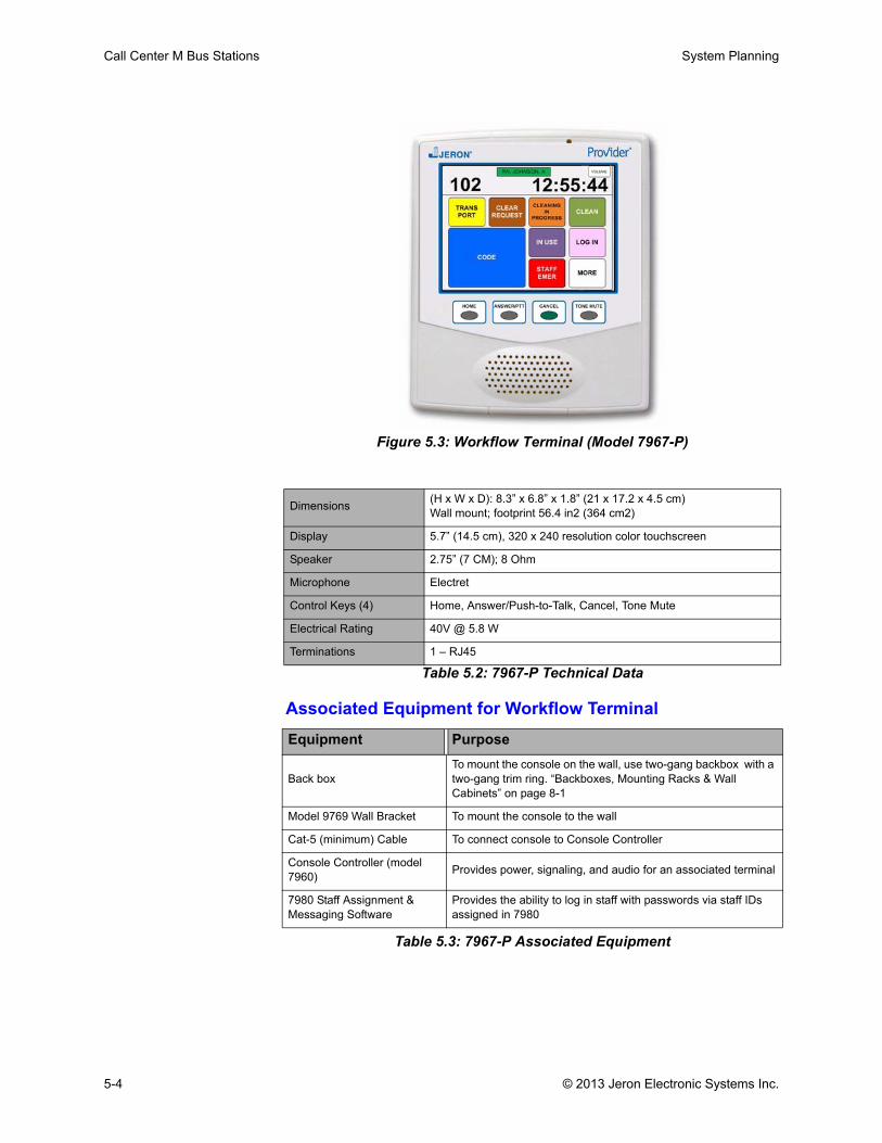
Call Center M Bus Stations System Planning
Figure 5.3: Workflow Terminal (Model 7967-P)
Table 5.2: 7967-P Technical Data
Associated Equipment for Workflow Terminal
Table 5.3: 7967-P Associated Equipment
Dimensions (H x W x D): 8.3” x 6.8” x 1.8” (21 x 17.2 x 4.5 cm)Wall mount; footprint 56.4 in2 (364 cm2)
Display 5.7” (14.5 cm), 320 x 240 resolution color touchscreen
Speaker 2.75” (7 CM); 8 Ohm
Microphone Electret
Control Keys (4) Home, Answer/Push-to-Talk, Cancel, Tone Mute
Electrical Rating 40V @ 5.8 W
Terminations 1 – RJ45
Equipment Purpose
Back boxTo mount the console on the wall, use two-gang backbox with a two-gang trim ring. “Backboxes, Mounting Racks & Wall Cabinets” on page 8-1
Model 9769 Wall Bracket To mount the console to the wall
Cat-5 (minimum) Cable To connect console to Console Controller
Console Controller (model 7960) Provides power, signaling, and audio for an associated terminal
7980 Staff Assignment & Messaging Software
Provides the ability to log in staff with passwords via staff IDs assigned in 7980
5-4 © 2013 Jeron Electronic Systems Inc.
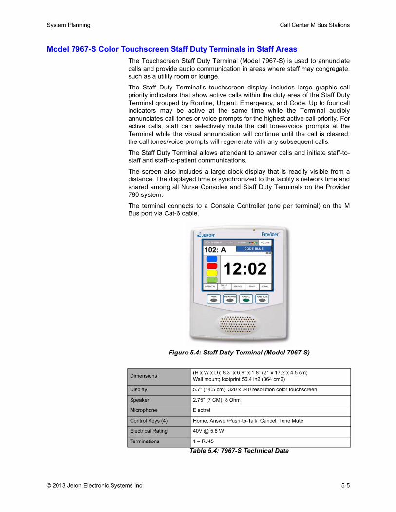
System Planning Call Center M Bus Stations
Model 7967-S Color Touchscreen Staff Duty Terminals in Staff AreasThe Touchscreen Staff Duty Terminal (Model 7967-S) is used to annunciatecalls and provide audio communication in areas where staff may congregate,such as a utility room or lounge.
The Staff Duty Terminal’s touchscreen display includes large graphic callpriority indicators that show active calls within the duty area of the Staff DutyTerminal grouped by Routine, Urgent, Emergency, and Code. Up to four callindicators may be active at the same time while the Terminal audiblyannunciates call tones or voice prompts for the highest active call priority. Foractive calls, staff can selectively mute the call tones/voice prompts at theTerminal while the visual annunciation will continue until the call is cleared;the call tones/voice prompts will regenerate with any subsequent calls.
The Staff Duty Terminal allows attendant to answer calls and initiate staff-to-staff and staff-to-patient communications.
The screen also includes a large clock display that is readily visible from adistance. The displayed time is synchronized to the facility’s network time andshared among all Nurse Consoles and Staff Duty Terminals on the Provider790 system.
The terminal connects to a Console Controller (one per terminal) on the MBus port via Cat-6 cable.
Figure 5.4: Staff Duty Terminal (Model 7967-S)
Table 5.4: 7967-S Technical Data
Dimensions (H x W x D): 8.3” x 6.8” x 1.8” (21 x 17.2 x 4.5 cm)Wall mount; footprint 56.4 in2 (364 cm2)
Display 5.7” (14.5 cm), 320 x 240 resolution color touchscreen
Speaker 2.75” (7 CM); 8 Ohm
Microphone Electret
Control Keys (4) Home, Answer/Push-to-Talk, Cancel, Tone Mute
Electrical Rating 40V @ 5.8 W
Terminations 1 – RJ45
© 2013 Jeron Electronic Systems Inc. 5-5

Call Center M Bus Stations System Planning
Associated Equipment for Staff Duty Terminal
Figure 5.5: 7967-S Associated Equipment
Model 7967-M Color Touchscreen Nurse Terminals in Staff AreasThe Touchscreen Nurse Terminal (Model 7967-M) is used to annunciate callsand provide audio communication in areas where staff may congregate, suchas a utility room or lounge.
The Nurse Terminal is used to place, receive, display, and answer calls frompatients and staff, providing bi-directional nonprivate audio communicationbetween rooms or other terminals via terminal speaker. The touchscreendisplays calls in the system in the order of call priority. It graphically displaysincoming calls including patient or staff station calling room number, bed (ifapplicable), call priority, elapsed time of call, and optionally the patient’sname, gender, acuity, and other relevant patient information.
The Nurse Terminal provides all the functionality of the Nurse Console (Model7965), including the ability to:
• Page staff manually, including staff selection, tag selection, free text
• Send service requests to staff
• Set rounding or reminders
• Upgrade call priority
• Change call status for callcord calls and feature bed calls
• Display multiple calls on a 2-call screen, 4-call screen or up to 30-call screen
• Use the Volume touchpoint to adjust alert tone and console volume
The Nurse Terminal connects to a Console Controller (one per terminal) onthe M Bus port via Cat-6 cable.
Equipment Purpose
Back boxTo mount the console on the wall, use two-gang backbox with a two-gang trim ring. “Backboxes, Mounting Racks & Wall Cabinets” on page 8-1
Model 9769 Wall Bracket To mount the console to the wall
Cat-5 (minimum) Cable To connect console to Console Controller
Console Controller (model 7960) Provides power, signaling, and audio for an associated terminal
5-6 © 2013 Jeron Electronic Systems Inc.
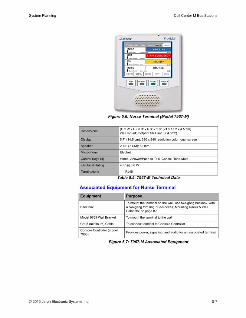
System Planning Call Center M Bus Stations
Figure 5.6: Nurse Terminal (Model 7967-M)
Table 5.5: 7967-M Technical Data
Associated Equipment for Nurse Terminal
Figure 5.7: 7967-M Associated Equipment
Dimensions (H x W x D): 8.3” x 6.8” x 1.8” (21 x 17.2 x 4.5 cm)Wall mount; footprint 56.4 in2 (364 cm2)
Display 5.7” (14.5 cm), 320 x 240 resolution color touchscreen
Speaker 2.75” (7 CM); 8 Ohm
Microphone Electret
Control Keys (4) Home, Answer/Push-to-Talk, Cancel, Tone Mute
Electrical Rating 40V @ 5.8 W
Terminations 1 – RJ45
Equipment Purpose
Back boxTo mount the terminal on the wall, use two-gang backbox with a two-gang trim ring. “Backboxes, Mounting Racks & Wall Cabinets” on page 8-1
Model 9769 Wall Bracket To mount the terminal to the wall
Cat-5 (minimum) Cable To connect terminal to Console Controller
Console Controller (model 7960) Provides power, signaling, and audio for an associated terminal
© 2013 Jeron Electronic Systems Inc. 5-7

Call Center M Bus Stations System Planning
5-8 © 2013 Jeron Electronic Systems Inc.

Chapter 6: System Wiring

.

System Planning Installation and Wiring
Installation and WiringThe Provider 790 system’s wiring strategy allows stations of the same type ina room to connect in series to a Room Controller. Audio stations connect viaCat 5/5e/6 cable. Peripheral stations connect in series to a Room Controllervia single 22 AWG UTP cable.
Observe the following precautions and specifications when planning systeminstallation.
Equipment Protection PrecautionThe Provider 790 Nurse Call System equipment contains low powermicroprocessor circuits which are sensitive to electrostatic discharge (ESD).Always observe the following precautions:
1. Do not remove bus stations from their static protective bags until they areready for installation. You should be grounded using an ESD wrist strapwhen handling these units. Use only Jeron furnished mounting hardware.
2. Observe the same precautions whenever a Nurse Console is opened forinspection or maintenance.
To avoid static charge:
1. Make sure callcords and patient stations are not close to or touching themetal bed frame or attendant when sheets are changed, as high levels ofESD are produced from this act.
2. Install the system in a continuous metallic conduit and backbox. Suchsystems are more resistant to failure due to static discharge or electricaldisturbance in general.
3. Attach the green ground wire clip on patient stations to the groundedbackbox.
Installation Precautions for Patient and Staff Safety Patient and staff safety depends on the following installation precautions:
• All installer-provided lighting or entertainment control relays (operatedvia pillow speakers) must have proper surge protection added to thecoils to damp the voltage transients (back EMF) created by the relaycoils.
• The system wiring must be isolated from earth grounds and fromother AC powered devices in order to protect patients and staff fromground faults and leakage currents. Some therapies may greatlyincrease patient risk from ground faults. Keep all system conductorsand grounds separate from earth grounds and carefully test to ensurethat ancillary equipment does not contribute leakage current to thesystem.
Pillow Speakers are not approved for use in oxygen enriched environmentsas defined by UL 1069. Where oxygen use or electrical susceptibility (seeabove) mandates non-electrical patient control devices, use the callcords.
Note: Only the Model 7958 Pullcord/Pushbutton Shower Station is water-resistant with wall gasket kit.
© 2013 Jeron Electronic Systems Inc. 6-1

Installation and Wiring System Planning
Planning System Wiring1. Obtain floor plans or blueprints to verify the locations of each station type.
If they are not documented on the floor plans, conduct a site survey todetermine the final locations.
2. Prepare a complete equipment list from architectural plans andspecifications. Additional surveys may be required to develop sufficientinformation to plan an effective installation, i.e. wire runs, location of theGateways, room numbering systems, coverage areas, zone and dutystation memberships, etc.
All stations are mounted in backboxes. The table on page 8-1 lists therecommended backbox types and covers for each station. Use only UL Listedbackboxes.
Wiring Precautions
• Wire all systems in accordance with local building codes, using thewiring diagrams in the Provider 790 Installation Manual.
• Use the exact wire type specified; use of any other kind may degradeor disable system performance.
• Do not run system wiring in common conduit or in close proximity (12inches minimum) with wiring for other systems (AC power distribution,fire alarm, entertainment or P.A. systems, etc.). Alternatively, use asolid divider in the cable tray to isolate the system wires.
• Verify that all wiring is free of shorts and earth grounds.
• All field wiring, power, data and audio is isolated from earth ground,chassis ground, and building ground.
Bus Types & Cables
J Bus • Main corridor trunk cable for all controllers (room/console/zone)
• Cat-6 (23 AWG) cable connects 9779 splitters in series to a Gateway.End of line termination resistor plug (Model 9778) must be installedon last J Bus 9779 splitter. RJ-45 connectors are used
• Factory furnished 6 inch, plug-ended cables connect room controllersto 9779 splitters. Controllers must be connected to 9779 splitters
• Cat-6 (23 AWG) cable must be wired according to T568B standard.The J Bus run must be continuous with no t-taps or any bridged taps
• Max. 700’ from Gateway to last Controller
Gateways/Switches• Cat-5/5e/6 cable connects Gateways to Nurse Call Isolated 8 Port
Ethernet Switch. RJ-45 connectors are used
• Cat-5/5e/6 cable connects Nurse Call Isolated 8 Port EthernetSwitches. RJ-45 connectors are used
6-2 © 2013 Jeron Electronic Systems Inc.
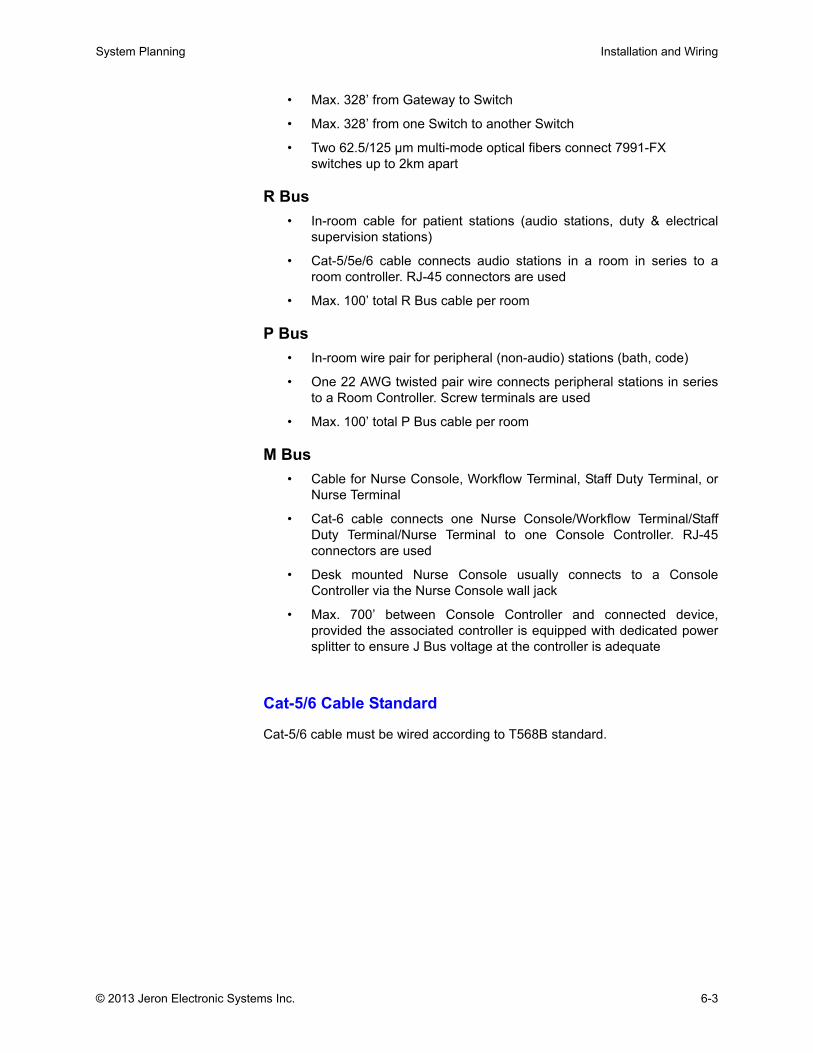
System Planning Installation and Wiring
• Max. 328’ from Gateway to Switch
• Max. 328’ from one Switch to another Switch
• Two 62.5/125 µm multi-mode optical fibers connect 7991-FX switches up to 2km apart
R Bus • In-room cable for patient stations (audio stations, duty & electrical
supervision stations)
• Cat-5/5e/6 cable connects audio stations in a room in series to aroom controller. RJ-45 connectors are used
• Max. 100’ total R Bus cable per room
P Bus • In-room wire pair for peripheral (non-audio) stations (bath, code)
• One 22 AWG twisted pair wire connects peripheral stations in seriesto a Room Controller. Screw terminals are used
• Max. 100’ total P Bus cable per room
M Bus• Cable for Nurse Console, Workflow Terminal, Staff Duty Terminal, or
Nurse Terminal
• Cat-6 cable connects one Nurse Console/Workflow Terminal/StaffDuty Terminal/Nurse Terminal to one Console Controller. RJ-45connectors are used
• Desk mounted Nurse Console usually connects to a ConsoleController via the Nurse Console wall jack
• Max. 700’ between Console Controller and connected device,provided the associated controller is equipped with dedicated powersplitter to ensure J Bus voltage at the controller is adequate
Cat-5/6 Cable Standard
Cat-5/6 cable must be wired according to T568B standard.
© 2013 Jeron Electronic Systems Inc. 6-3
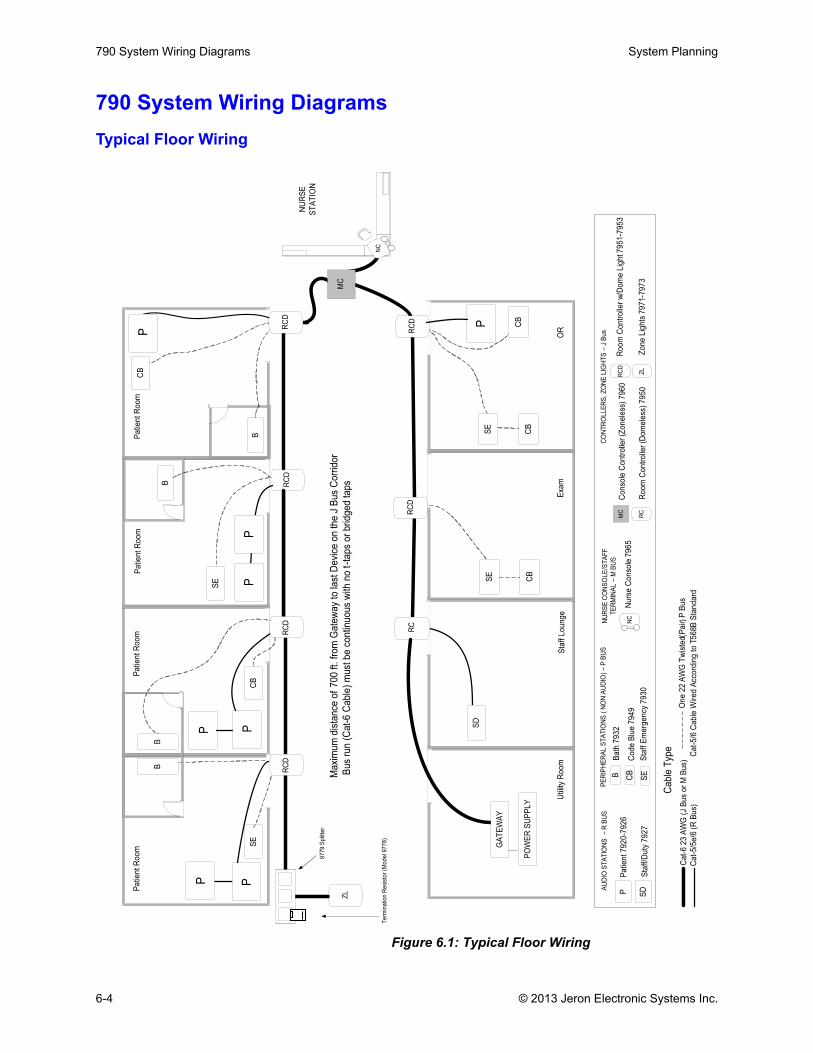
790 System Wiring Diagrams System Planning
790 System Wiring DiagramsTypical Floor Wiring
Figure 6.1: Typical Floor Wiring
RC
DR
CD
RC
D
RC
DR
CD
P
B
NC
SE
NU
RS
E
ST
AT
ION
PPa
tie
nt
Ro
om
Pa
tie
nt
Ro
om
Pa
tie
nt
Ro
om
Pa
tie
nt
Ro
om
Exa
mS
taff
Lo
un
ge
OR
MC
SE
NC
Utility
Ro
om
BB
ath
79
32
CB
Co
de
Blu
e7
94
9
SE
Sta
ffE
me
rge
ncy
79
30
PE
RIP
HE
RA
LS
TA
TIO
NS
(N
ON
AU
DIO
)–
PB
US
AU
DIO
ST
AT
ION
S–
RB
US
Pa
tie
nt7
92
0-7
92
6
SD
Sta
ff/D
uty
79
27
NU
RS
EC
ON
SO
LE
/ST
AF
F
TE
RM
INA
L–
MB
US
Nu
rse
Co
nso
le7
96
5
CO
NT
RO
LLE
RS
,Z
ON
ELIG
HT
S–
JB
us
Cable
Type
Ca
t-6
23
AW
G(J
Bu
so
rM
Bu
s)
Ca
t-5/5
e/6
(RB
us)
On
e2
2A
WG
Tw
iste
dP
air
(P
Bu
s)
Ca
t-5
/6C
ab
leW
ire
dA
cco
rdin
gto
T5
68B
Sta
nd
ard
RC
ZL
Zo
ne
Lig
hts
79
71-7
97
3
MC
Co
nso
leC
on
tro
lle
r(Z
on
ele
ss)
79
60
RC
Ro
om
Co
ntr
olle
r(D
om
ele
ss)
79
50
B
Ro
om
Co
ntr
olle
rw
/Do
me
Lig
ht7
95
1-7
95
3R
CD
GA
TE
WA
Y
PO
WE
RS
UP
PL
Y
Term
ination
Resis
tor
(Model9778)
Maxim
um
dis
tance
of
700
ft.fr
om
Gate
way
tola
stD
evic
eon
the
JB
us
Corr
idor
Bus
run
(Cat-
6C
able
)m
ustbe
continuous
with
no
t-ta
ps
or
bridged
taps
PP
B
PC
BP
PB
P
SE
CB
RC
DR
CD
RC
D
RC
DR
CD
P
CB
CB
SE
CB
SD
ZL
9779
Splitter
6-4 © 2013 Jeron Electronic Systems Inc.
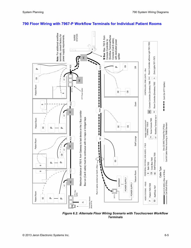
System Planning 790 System Wiring Diagrams
790 Floor Wiring with 7967-P Workflow Terminals for Individual Patient Rooms
Figure 6.2: Alternate Floor Wiring Scenario with Touchscreen Workflow Terminals
RC
DR
CD
RC
D
RC
DR
CD
P
B
NC
SE
NU
RS
E
ST
AT
ION
PPa
tie
nt
Ro
om
Pa
tie
nt
Ro
om
Pa
tie
nt
Ro
om
Pa
tie
nt
Ro
om
Exa
mS
taff
Lo
un
ge
OR
MC
SE
NC
Te
leco
mR
oo
m
BB
ath
79
32
CB
Co
de
Blu
e7
94
9
SE
Sta
ffE
me
rge
ncy
79
30
PE
RIP
HE
RA
LS
TA
TIO
NS
(N
ON
AU
DIO
)–
PB
US
AU
DIO
ST
AT
ION
S–
RB
US
Pa
tie
nt7
92
0-7
92
6
SD
Sta
ff/D
uty
79
27
NU
RS
EC
ON
SO
LE
/ST
AF
F
TE
RM
INA
L–
MB
US
Nu
rse
Co
nso
le7
96
5
CO
NT
RO
LLE
RS
,Z
ON
ELIG
HT
S–
JB
us
Cable
Type
Ca
t-6
23
AW
G(J
Bu
s)
Ca
t-5/5
e/6
(MB
us
or
RB
us)
On
e2
2A
WG
Tw
iste
dP
air
(PB
us)
Ca
t-5
/6C
ab
leW
ire
dA
cco
rdin
gto
T5
68B
Sta
nd
ard
RC
ZL
Zo
ne
Lig
hts
79
71-7
97
3
MC
Co
nso
leC
on
tro
lle
r(Z
on
ele
ss)
79
60
RC
Ro
om
Co
ntr
olle
r(D
om
ele
ss)
79
50
B
Ro
om
Co
ntr
olle
rw
/Do
me
Lig
ht7
95
1-7
95
3R
CD
GA
TE
WA
Y
PO
WE
RS
UP
PL
Y
Term
ination
Resis
tor
(Model9778)
Maxim
um
dis
tance
of
700
ft.fr
om
Gate
way
tola
stdevic
eon
the
JB
us
corr
idor
Bus
run
(Cat-
6ca
ble
)m
ustbe
continuous
with
no
t-ta
ps
or
bridged
taps
PP
B
PC
BP
B
P
SE
CB
RC
DR
CD
RC
D
RC
DR
CD
P
CB
CB
SE
CB
SD
ZL
9777
Pow
er
Splitter
MC
WT
WT
Wo
rkflo
wT
erm
ina
l7
96
7-P
MC
WT
P
MC
WT
MC
WT
9777-2
9779
JB
us
Splitter
9777-1
No
te:
Fo
ra
dd
itio
na
lw
ork
flo
w
term
ina
ls,
con
su
ltfa
cto
ryfo
r
po
we
rsu
pp
lyre
qu
ire
me
nts
.
RC
DR
CD
RC
D
RC
DR
CD
P
B
NC
SE
NU
RS
E
ST
AT
ION
PPa
tie
nt
Ro
om
Pa
tie
nt
Ro
om
Pa
tie
nt
Ro
om
Pa
tie
nt
Ro
om
Exa
mS
taff
Lo
un
ge
OR
MC
SE
NC
Te
leco
mR
oo
m
BB
ath
79
32
CB
Co
de
Blu
e7
94
9
SE
Sta
ffE
me
rge
ncy
79
30
PE
RIP
HE
RA
LS
TA
TIO
NS
(N
ON
AU
DIO
)–
PB
US
AU
DIO
ST
AT
ION
S–
RB
US
Pa
tie
nt7
92
0-7
92
6
SD
Sta
ff/D
uty
79
27
NU
RS
EC
ON
SO
LE
/ST
AF
F
TE
RM
INA
L–
MB
US
Nu
rse
Co
nso
le7
96
5
CO
NT
RO
LLE
RS
,Z
ON
ELIG
HT
S–
JB
us
Cable
Type
Ca
t-6
23
AW
G(J
Bu
so
rM
Bu
s)
Ca
t-5/5
e/6
(RB
us)
On
e2
2A
WG
Tw
iste
dP
air
(PB
us)
Ca
t-5
/6C
ab
leW
ire
dA
cco
rdin
gto
T5
68B
Sta
nd
ard
RC
ZL
Zo
ne
Lig
hts
79
71-7
97
3
MC
Co
nso
leC
on
tro
lle
r(Z
on
ele
ss)
79
60
RC
Ro
om
Co
ntr
olle
r(D
om
ele
ss)
79
50
B
Ro
om
Co
ntr
olle
rw
/Do
me
Lig
ht7
95
1-7
95
3R
CD
GA
TE
WA
Y
PO
WE
RS
UP
PL
Y
Term
ination
Resis
tor
(Model9778)
Maxim
um
dis
tance
of
700
ft.fr
om
Gate
way
tola
stdevic
eon
the
JB
us
corr
idor
Bus
run
(Cat-
6ca
ble
)m
ustbe
continuous
with
no
t-ta
ps
or
bridged
taps
PP
B
PC
BP
B
P
SE
CB
RC
DR
CD
RC
D
RC
DR
CD
P
CB
CB
SE
CB
SD
ZL
9777
Pow
er
Splitter
MCW
T
WT
Wo
rkflo
wT
erm
ina
l7
96
7-P
MC
WT
P
MC
WT
MC
WT
9777-2
9779
JB
us
Splitter
9777-1
No
te:
Fo
ra
dd
itio
na
lw
ork
flo
w
term
ina
ls,
con
su
ltfa
cto
ryfo
r
po
we
rsu
pp
lyre
qu
ire
me
nts
.
Ru
nin
sa
me
co
nd
uit
as
Ca
t-6
JB
us
Ca
t-6
(fo
r9
77
7S
plitt
er)
PO
WE
RS
UP
PL
Y
MB
us
:M
ax.
70
0ft
.fr
om
Co
nso
leC
on
tro
lle
rto
Wo
rkflo
wT
erm
ina
l/N
urs
e
Co
nso
le(C
at-
6ca
ble
),
with
de
dic
ate
dp
ow
er
sp
litt
er
© 2013 Jeron Electronic Systems Inc. 6-5
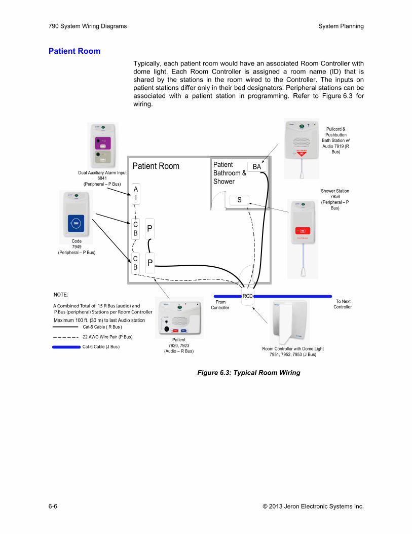
790 System Wiring Diagrams System Planning
Patient RoomTypically, each patient room would have an associated Room Controller withdome light. Each Room Controller is assigned a room name (ID) that isshared by the stations in the room wired to the Controller. The inputs onpatient stations differ only in their bed designators. Peripheral stations can beassociated with a patient station in programming. Refer to Figure 6.3 forwiring.
Figure 6.3: Typical Room Wiring
RCD
BA
C
B
Patient Room
S
PC
B
Pullcord &
Pushbutton
Bath Station w/
Audio 7919 (R
Bus)
Shower Station
7958
(Peripheral – P
Bus)
Patient
Bathroom &
Shower
Room Controller with Dome Light
7951, 7952, 7953 (J Bus)
Code
7949
(Peripheral – P Bus)
P
Patient
7920, 7923
(Audio – R Bus)
To Next
Controller
From
Controller
A
I
Dual Auxiliary Alarm Input
6841
(Peripheral – P Bus)
NOTE:
Maximum 100 ft. (30 m) to last Audio station
Cat-5 Cable ( R Bus )
22 AWG Wire Pair (P Bus)
Cat-6 Cable (J Bus )
A Combined Total of 15 R Bus (audio) andP Bus (peripheral) Stations per Room Controller
6-6 © 2013 Jeron Electronic Systems Inc.

System Planning 790 System Wiring Diagrams
© 2013 Jeron Electronic Systems Inc. 6-7
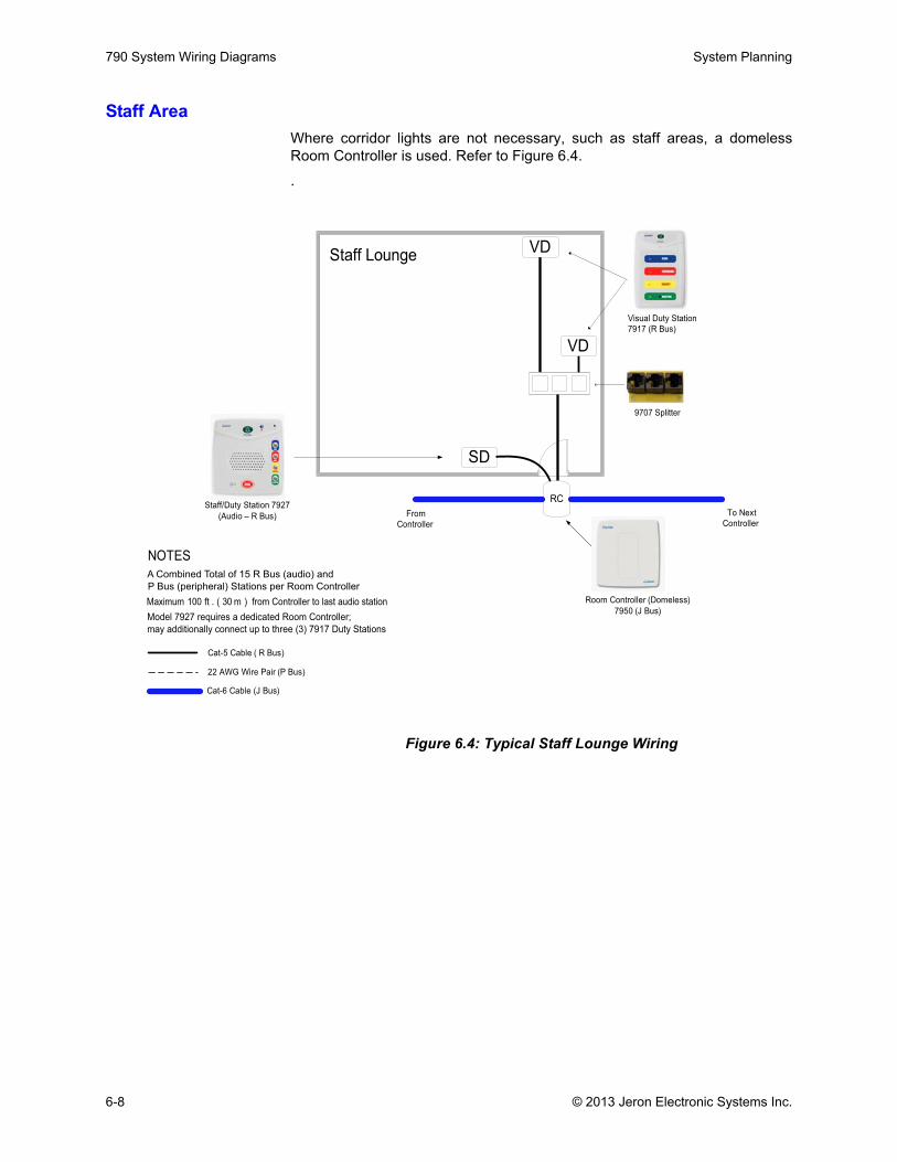
790 System Wiring Diagrams System Planning
Staff AreaWhere corridor lights are not necessary, such as staff areas, a domelessRoom Controller is used. Refer to Figure 6.4.
.
Figure 6.4: Typical Staff Lounge Wiring
RC
Staff Lounge
SD
Room Controller (Domeless)
7950 (J Bus)
Cat-5 Cable ( R Bus)
22 AWG Wire Pair (P Bus)
To Next
Controller
From
Controller
Cat-6 Cable (J Bus)
Staff/Duty Station 7927
(Audio – R Bus)
Model 7927 requires a dedicated Room Controller;
may additionally connect up to three (3) 7917 Duty Stations
NOTES
Maximum 100 ft . ( 30 m ) from Controller to last audio station
A Combined Total of 15 R Bus (audio) and
P Bus (peripheral) Stations per Room Controller
VD
VD
9707 Splitter
Visual Duty Station
7917 (R Bus)
6-8 © 2013 Jeron Electronic Systems Inc.
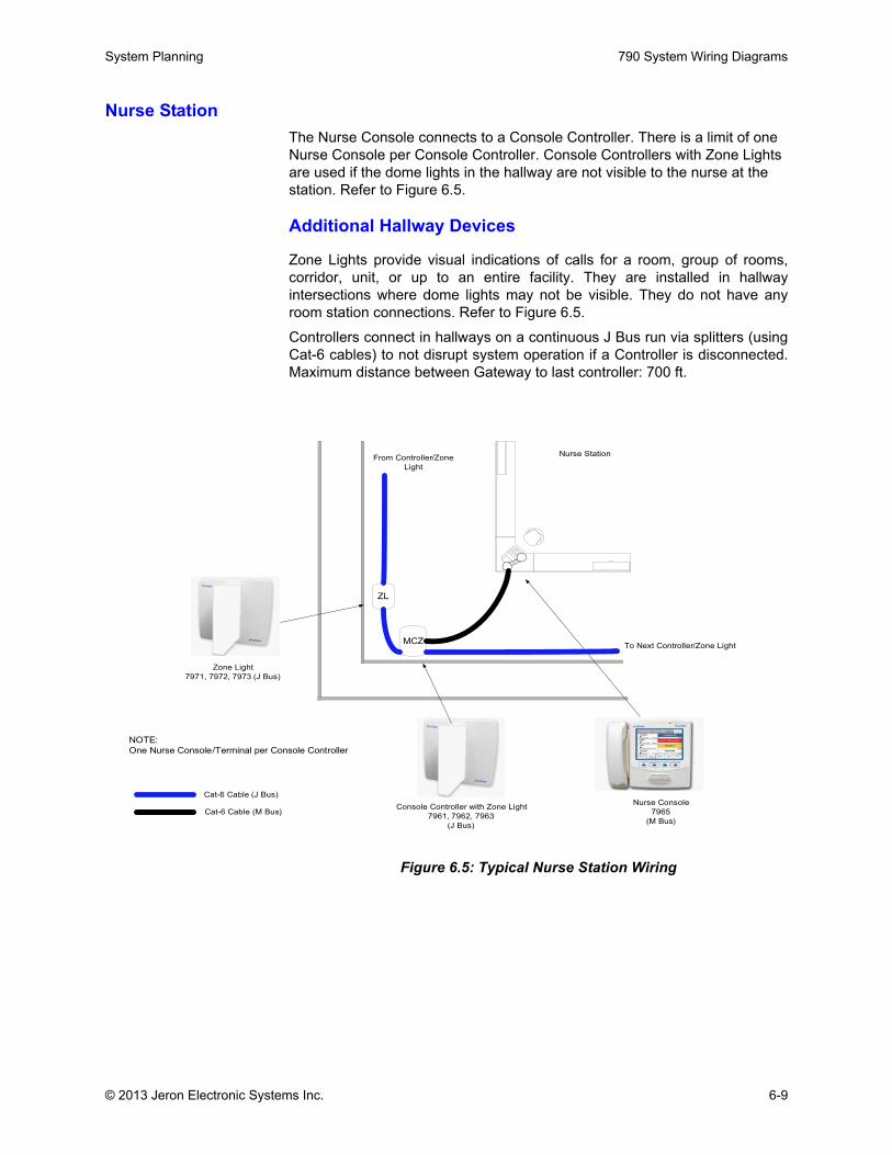
System Planning 790 System Wiring Diagrams
Nurse StationThe Nurse Console connects to a Console Controller. There is a limit of one Nurse Console per Console Controller. Console Controllers with Zone Lights are used if the dome lights in the hallway are not visible to the nurse at the station. Refer to Figure 6.5.
Additional Hallway Devices
Zone Lights provide visual indications of calls for a room, group of rooms,corridor, unit, or up to an entire facility. They are installed in hallwayintersections where dome lights may not be visible. They do not have anyroom station connections. Refer to Figure 6.5.
Controllers connect in hallways on a continuous J Bus run via splitters (usingCat-6 cables) to not disrupt system operation if a Controller is disconnected.Maximum distance between Gateway to last controller: 700 ft.
Figure 6.5: Typical Nurse Station Wiring
Zone Light
7971, 7972, 7973 (J Bus)
NOTE:
One Nurse Console/Terminal per Console Controller
Cat-6 Cable (M Bus)
Nurse Station
Console Controller with Zone Light
7961, 7962, 7963
(J Bus)
MCZ
ZL
Nurse Console
7965
(M Bus)
To Next Controller/Zone Light
From Controller/Zone
Light
Cat-6 Cable (J Bus)
© 2013 Jeron Electronic Systems Inc. 6-9
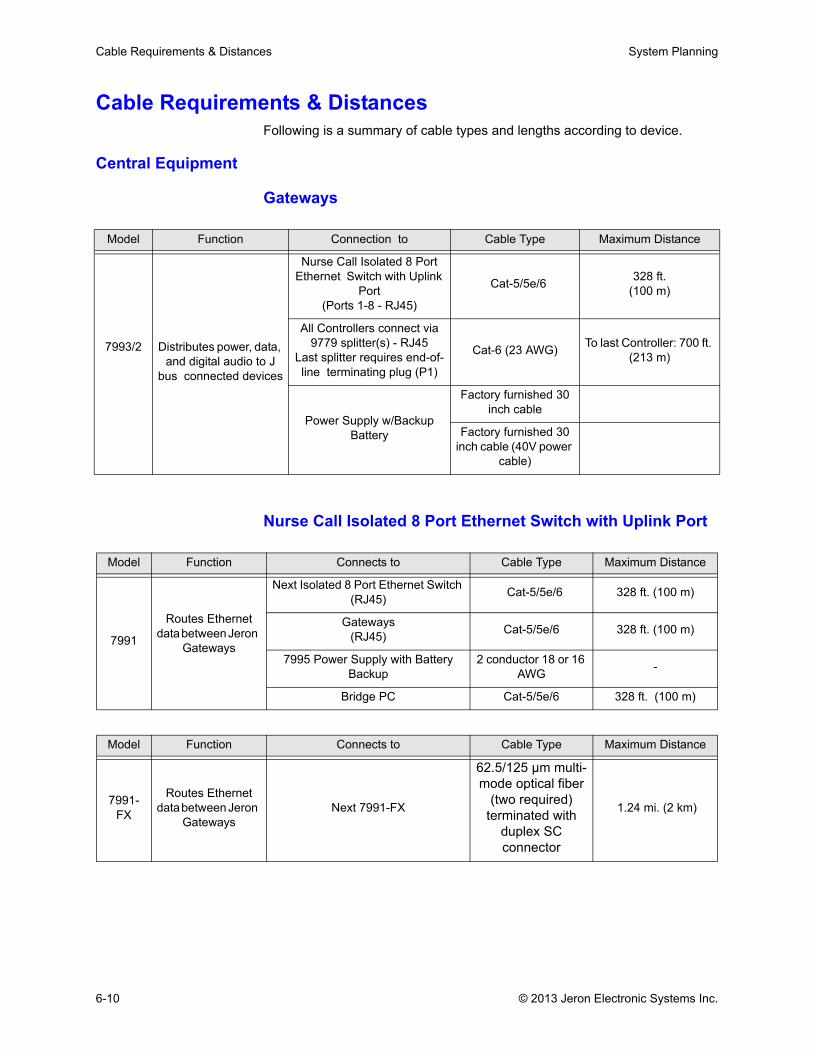
Cable Requirements & Distances System Planning
Cable Requirements & DistancesFollowing is a summary of cable types and lengths according to device.
Central Equipment
Gateways
Nurse Call Isolated 8 Port Ethernet Switch with Uplink Port
Model Function Connection to Cable Type Maximum Distance
7993/2 Distributes power, data, and digital audio to J
bus connected devices
Nurse Call Isolated 8 Port Ethernet Switch with Uplink
Port(Ports 1-8 - RJ45)
Cat-5/5e/6 328 ft. (100 m)
All Controllers connect via 9779 splitter(s) - RJ45
Last splitter requires end-of-line terminating plug (P1)
Cat-6 (23 AWG) To last Controller: 700 ft. (213 m)
Power Supply w/Backup Battery
Factory furnished 30 inch cable
Factory furnished 30 inch cable (40V power
cable)
Model Function Connects to Cable Type Maximum Distance
7991
Routes Ethernet data between Jeron
Gateways
Next Isolated 8 Port Ethernet Switch (RJ45) Cat-5/5e/6 328 ft. (100 m)
Gateways(RJ45) Cat-5/5e/6 328 ft. (100 m)
7995 Power Supply with Battery Backup
2 conductor 18 or 16 AWG -
Bridge PC Cat-5/5e/6 328 ft. (100 m)
Model Function Connects to Cable Type Maximum Distance
7991-FX
Routes Ethernet data between Jeron
GatewaysNext 7991-FX
62.5/125 µm multi-mode optical fiber
(two required) terminated with
duplex SC connector
1.24 mi. (2 km)
6-10 © 2013 Jeron Electronic Systems Inc.
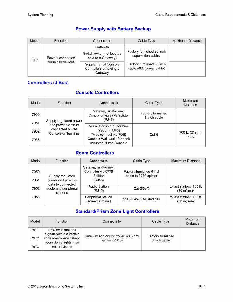
System Planning Cable Requirements & Distances
Power Supply with Battery Backup
Controllers (J Bus)
Console Controllers
Room Controllers
Standard/Prism Zone Light Controllers
Model Function Connects to Cable Type Maximum Distance
7995 Powers connected nurse call devices
GatewayFactory furnished 30 inch
supervision cables
Factory furnished 30 inch cable (40V power cable)
Switch (when not located next to a Gateway)
Supplemental Console Controllers on a single
Gateway
Model Function Connects to Cable Type Maximum Distance
7960
7961
7962
7963
Supply regulated power and provide data to connected Nurse
Console or Terminal
Gateway and/or next Controller via 9779 Splitter
(RJ45)
Factory furnished6 inch cable
Nurse Console or Terminal (7960) (RJ45)
*May connect via 7969 Console Wall Jack for desk
mounted Nurse Console
Cat-6 700 ft. (213 m) max.
Model Function Connects to Cable Type Maximum Distance
7950
7951
7952
7953
Supply regulated power and provide data to connected
audio and peripheral stations
Gateway and/or next Controller via 9779
Splitter(RJ45)
Factory furnished 6 inch cable to 9779 splitter
Audio Station (RJ45) Cat-5/5e/6 to last station: 100 ft.
(30 m) max
Peripheral Station(screw terminal) one 22 AWG twisted pair to last station: 100 ft.
(30 m) max
Model Function Connects to Cable Type Maximum Distance
7971
7972
7973
Provide visual call signals within a certain
zone area where patient room dome lights may
not be visible
Gateway and/or Controller via 9779 Splitter (RJ45)
Factory furnished6 inch cable
© 2013 Jeron Electronic Systems Inc. 6-11
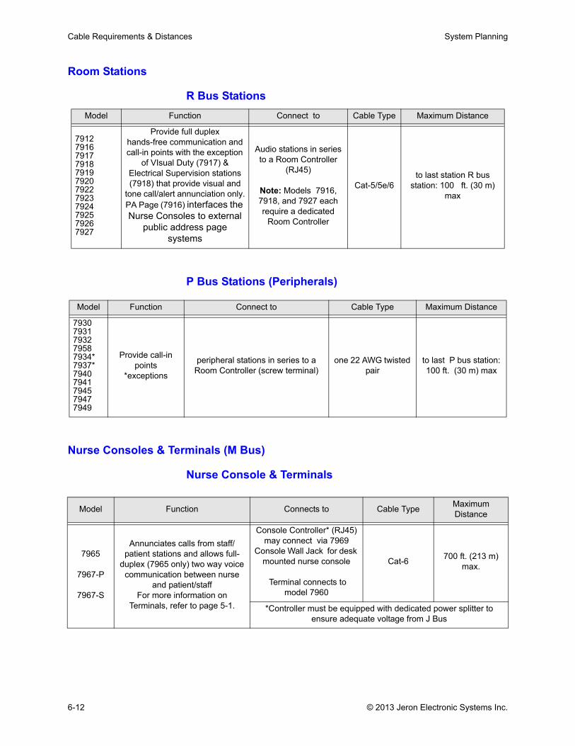
Cable Requirements & Distances System Planning
Room Stations
R Bus Stations
P Bus Stations (Peripherals)
Nurse Consoles & Terminals (M Bus)
Nurse Console & Terminals
Model Function Connect to Cable Type Maximum Distance
791279167917791879197920792279237924792579267927
Provide full duplexhands-free communication and call-in points with the exception
of VIsual Duty (7917) & Electrical Supervision stations (7918) that provide visual and
tone call/alert annunciation only.PA Page (7916) interfaces the Nurse Consoles to external
public address page systems
Audio stations in series to a Room Controller
(RJ45)
Note: Models 7916, 7918, and 7927 each require a dedicated
Room Controller
Cat-5/5e/6to last station R bus
station: 100 ft. (30 m) max
Model Function Connect to Cable Type Maximum Distance
79307931793279587934*7937*79407941794579477949
Provide call-in points
*exceptions
peripheral stations in series to a Room Controller (screw terminal)
one 22 AWG twisted pair
to last P bus station: 100 ft. (30 m) max
Model Function Connects to Cable Type Maximum Distance
7965
7967-P
7967-S
Annunciates calls from staff/patient stations and allows full-
duplex (7965 only) two way voice communication between nurse
and patient/staff For more information on
Terminals, refer to page 5-1.
Console Controller* (RJ45)may connect via 7969
Console Wall Jack for desk mounted nurse console
Terminal connects to model 7960
Cat-6 700 ft. (213 m) max.
*Controller must be equipped with dedicated power splitter to ensure adequate voltage from J Bus
6-12 © 2013 Jeron Electronic Systems Inc.

Chapter 7: Device Installation

.
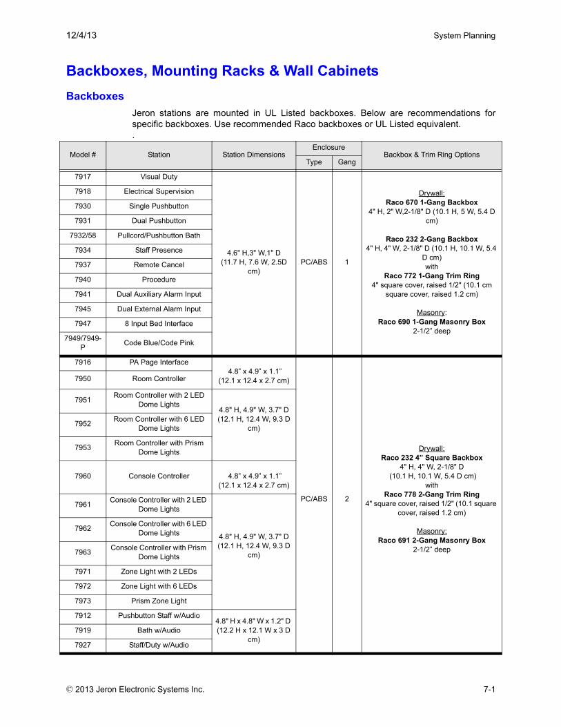
12/4/13 System Planning
Backboxes, Mounting Racks & Wall Cabinets Backboxes
Jeron stations are mounted in UL Listed backboxes. Below are recommendations forspecific backboxes. Use recommended Raco backboxes or UL Listed equivalent..
Model # Station Station DimensionsEnclosure
Backbox & Trim Ring OptionsType Gang
7917 Visual Duty
4.6" H,3" W,1" D(11.7 H, 7.6 W, 2.5D
cm)PC/ABS 1
Drywall: Raco 670 1-Gang Backbox
4" H, 2" W,2-1/8" D (10.1 H, 5 W, 5.4 D cm)
Raco 232 2-Gang Backbox4" H, 4" W, 2-1/8" D (10.1 H, 10.1 W, 5.4
D cm)with
Raco 772 1-Gang Trim Ring4" square cover, raised 1/2" (10.1 cm
square cover, raised 1.2 cm)
Masonry:Raco 690 1-Gang Masonry Box
2-1/2” deep
7918 Electrical Supervision
7930 Single Pushbutton
7931 Dual Pushbutton
7932/58 Pullcord/Pushbutton Bath
7934 Staff Presence
7937 Remote Cancel
7940 Procedure
7941 Dual Auxiliary Alarm Input
7945 Dual External Alarm Input
7947 8 Input Bed Interface
7949/7949-P Code Blue/Code Pink
7916 PA Page Interface 4.8” x 4.9” x 1.1”
(12.1 x 12.4 x 2.7 cm)
PC/ABS 2
Drywall:Raco 232 4” Square Backbox
4" H, 4" W, 2-1/8" D (10.1 H, 10.1 W, 5.4 D cm)
with Raco 778 2-Gang Trim Ring
4" square cover, raised 1/2" (10.1 square cover, raised 1.2 cm)
Masonry:Raco 691 2-Gang Masonry Box
2-1/2” deep
7950 Room Controller
7951 Room Controller with 2 LED Dome Lights
4.8" H, 4.9" W, 3.7" D(12.1 H, 12.4 W, 9.3 D
cm)7952 Room Controller with 6 LED Dome Lights
7953 Room Controller with Prism Dome Lights
7960 Console Controller 4.8” x 4.9” x 1.1” (12.1 x 12.4 x 2.7 cm)
7961 Console Controller with 2 LED Dome Lights
4.8" H, 4.9" W, 3.7" D(12.1 H, 12.4 W, 9.3 D
cm)
7962 Console Controller with 6 LED Dome Lights
7963 Console Controller with Prism Dome Lights
7971 Zone Light with 2 LEDs
7972 Zone Light with 6 LEDs
7973 Prism Zone Light
7912 Pushbutton Staff w/Audio4.8" H x 4.8" W x 1.2" D (12.2 H x 12.1 W x 3 D
cm)7919 Bath w/Audio
7927 Staff/Duty w/Audio
© 2013 Jeron Electronic Systems Inc. 7-1
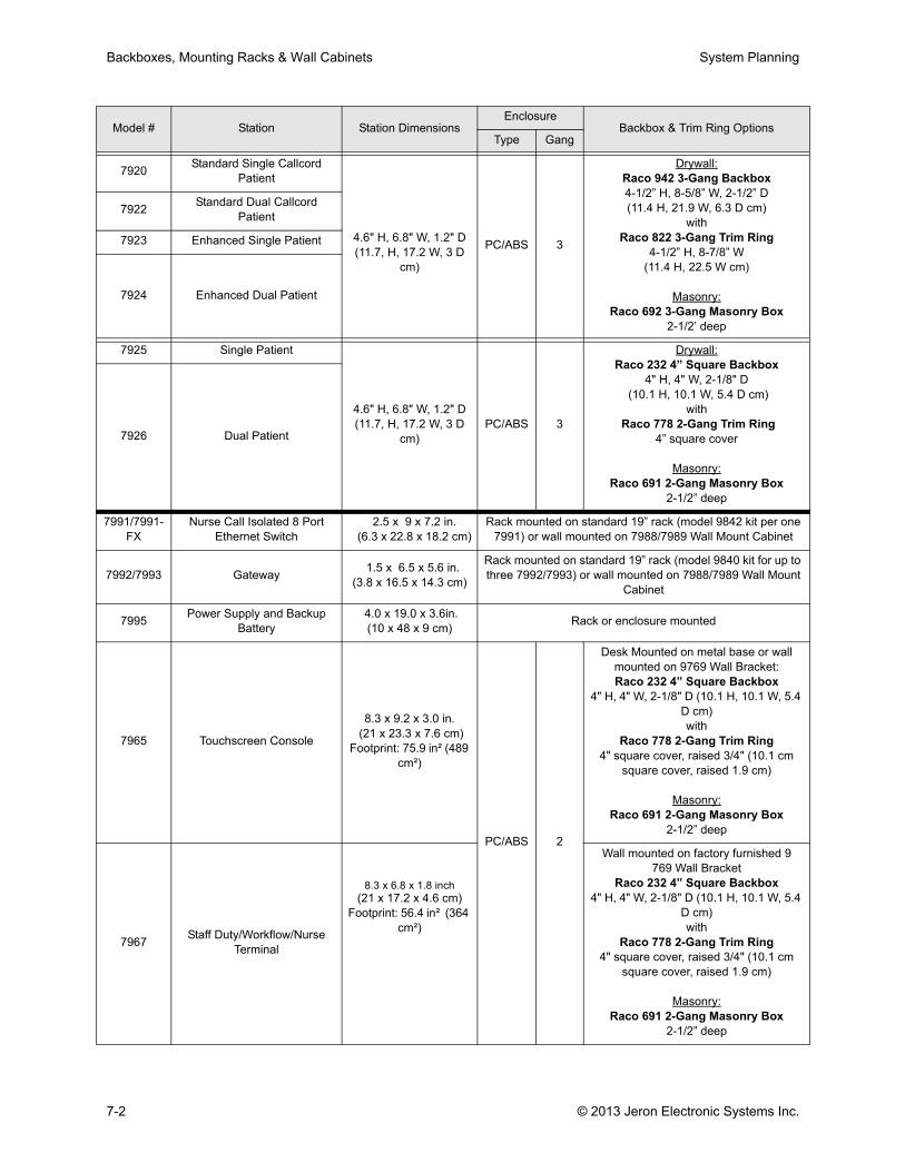
Backboxes, Mounting Racks & Wall Cabinets System Planning
7920 Standard Single Callcord Patient
4.6" H, 6.8" W, 1.2" D(11.7, H, 17.2 W, 3 D
cm)
PC/ABS 3
Drywall:Raco 942 3-Gang Backbox4-1/2” H, 8-5/8” W, 2-1/2” D(11.4 H, 21.9 W, 6.3 D cm)
withRaco 822 3-Gang Trim Ring
4-1/2” H, 8-7/8” W (11.4 H, 22.5 W cm)
Masonry:Raco 692 3-Gang Masonry Box
2-1/2’ deep
7922 Standard Dual Callcord Patient
7923 Enhanced Single Patient
7924 Enhanced Dual Patient
7925 Single Patient
4.6" H, 6.8" W, 1.2" D(11.7, H, 17.2 W, 3 D
cm)PC/ABS 3
Drywall:Raco 232 4” Square Backbox
4" H, 4" W, 2-1/8" D (10.1 H, 10.1 W, 5.4 D cm)
with Raco 778 2-Gang Trim Ring
4” square cover
Masonry:Raco 691 2-Gang Masonry Box
2-1/2” deep
7926 Dual Patient
7991/7991-FX
Nurse Call Isolated 8 Port Ethernet Switch
2.5 x 9 x 7.2 in. (6.3 x 22.8 x 18.2 cm)
Rack mounted on standard 19” rack (model 9842 kit per one 7991) or wall mounted on 7988/7989 Wall Mount Cabinet
7992/7993 Gateway 1.5 x 6.5 x 5.6 in. (3.8 x 16.5 x 14.3 cm)
Rack mounted on standard 19” rack (model 9840 kit for up to three 7992/7993) or wall mounted on 7988/7989 Wall Mount
Cabinet
7995 Power Supply and Backup Battery
4.0 x 19.0 x 3.6in. (10 x 48 x 9 cm) Rack or enclosure mounted
7965 Touchscreen Console
8.3 x 9.2 x 3.0 in. (21 x 23.3 x 7.6 cm)
Footprint: 75.9 in² (489 cm²)
PC/ABS 2
Desk Mounted on metal base or wall mounted on 9769 Wall Bracket:Raco 232 4” Square Backbox
4" H, 4" W, 2-1/8" D (10.1 H, 10.1 W, 5.4 D cm)with
Raco 778 2-Gang Trim Ring4" square cover, raised 3/4" (10.1 cm
square cover, raised 1.9 cm)
Masonry:Raco 691 2-Gang Masonry Box
2-1/2” deep
7967 Staff Duty/Workflow/Nurse Terminal
8.3 x 6.8 x 1.8 inch(21 x 17.2 x 4.6 cm)
Footprint: 56.4 in² (364 cm²)
Wall mounted on factory furnished 9769 Wall Bracket
Raco 232 4” Square Backbox4" H, 4" W, 2-1/8" D (10.1 H, 10.1 W, 5.4
D cm)with
Raco 778 2-Gang Trim Ring4" square cover, raised 3/4" (10.1 cm
square cover, raised 1.9 cm)
Masonry:Raco 691 2-Gang Masonry Box
2-1/2” deep
Model # Station Station DimensionsEnclosure
Backbox & Trim Ring OptionsType Gang
7-2 © 2013 Jeron Electronic Systems Inc.
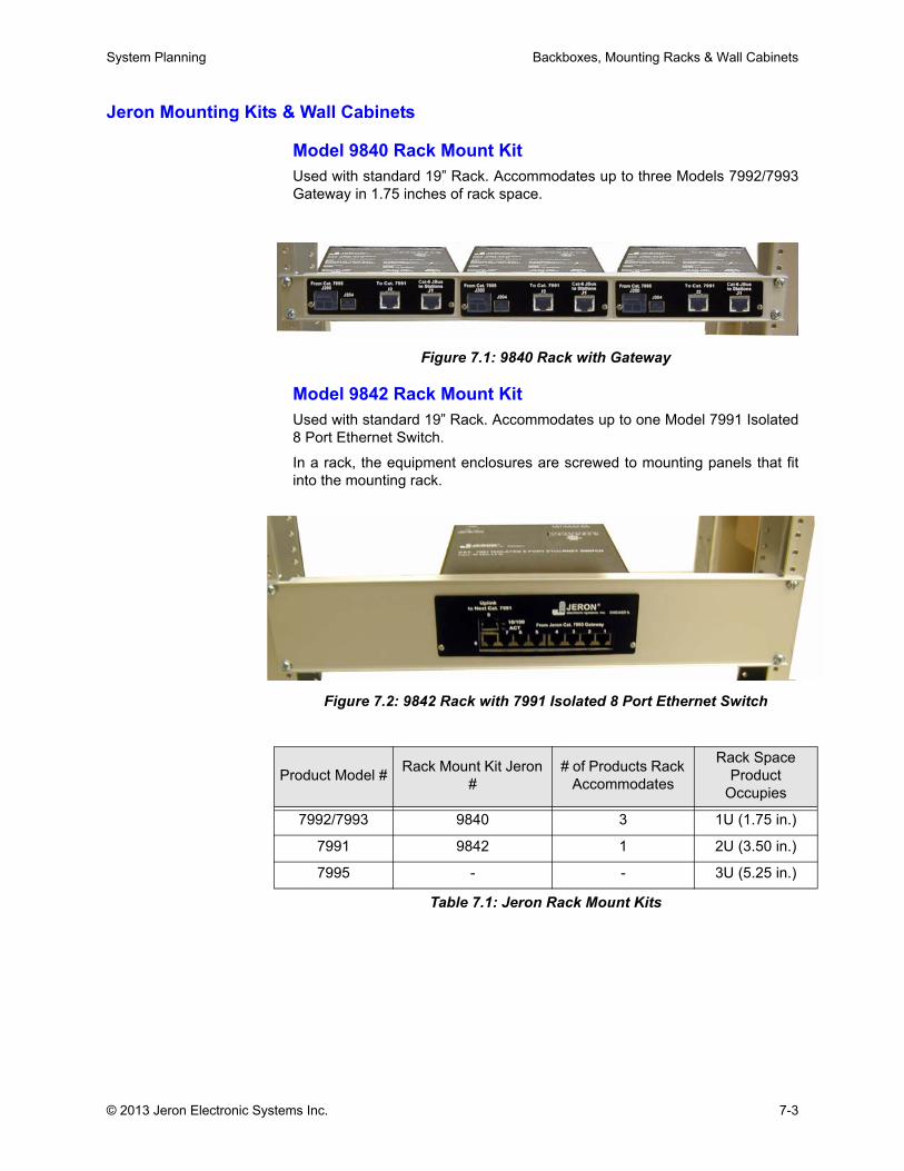
System Planning Backboxes, Mounting Racks & Wall Cabinets
Jeron Mounting Kits & Wall Cabinets
Model 9840 Rack Mount KitUsed with standard 19” Rack. Accommodates up to three Models 7992/7993Gateway in 1.75 inches of rack space.
Figure 7.1: 9840 Rack with Gateway
Model 9842 Rack Mount KitUsed with standard 19” Rack. Accommodates up to one Model 7991 Isolated8 Port Ethernet Switch.
In a rack, the equipment enclosures are screwed to mounting panels that fitinto the mounting rack.
Figure 7.2: 9842 Rack with 7991 Isolated 8 Port Ethernet Switch
Product Model # Rack Mount Kit Jeron #
# of Products Rack Accommodates
Rack Space Product
Occupies
7992/7993 9840 3 1U (1.75 in.)
7991 9842 1 2U (3.50 in.)
7995 - - 3U (5.25 in.)
Table 7.1: Jeron Rack Mount Kits
© 2013 Jeron Electronic Systems Inc. 7-3
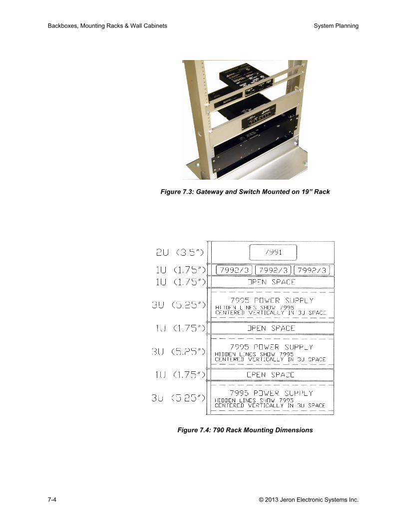
Backboxes, Mounting Racks & Wall Cabinets System Planning
Figure 7.3: Gateway and Switch Mounted on 19” Rack
Figure 7.4: 790 Rack Mounting Dimensions
7-4 © 2013 Jeron Electronic Systems Inc.
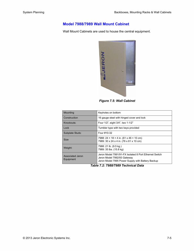
System Planning Backboxes, Mounting Racks & Wall Cabinets
Model 7988/7989 Wall Mount Cabinet
Wall Mount Cabinets are used to house the central equipment.
Figure 7.5: Wall Cabinet
Table 7.2: 7988/7989 Technical Data
Mounting Keyholes on bottom
Construction 16 gauge steel with hinged cover and lock
Knockouts: Four 1/2”, eight 3/4”, two 1-1/2”
Lock Tumbler type with two keys provided
Subplate Studs: Four #10-32
Size 7988: 24 × 18 × 4 in. (61 x 46 × 10 cm) 7989: 30 x 24 x 4 in. (76 x 61 x 10 cm)
Weight: 7988: 21 lb. (9.5 kg.)7989: 35 lbs. (15.8 kg)
Associated Jeron Equipment
Jeron Model 7991/91-FX Isolated 8 Port Ethernet SwitchJeron Model 7992/93 GatewayJeron Model 7995 Power Supply with Battery Backup
© 2013 Jeron Electronic Systems Inc. 7-5
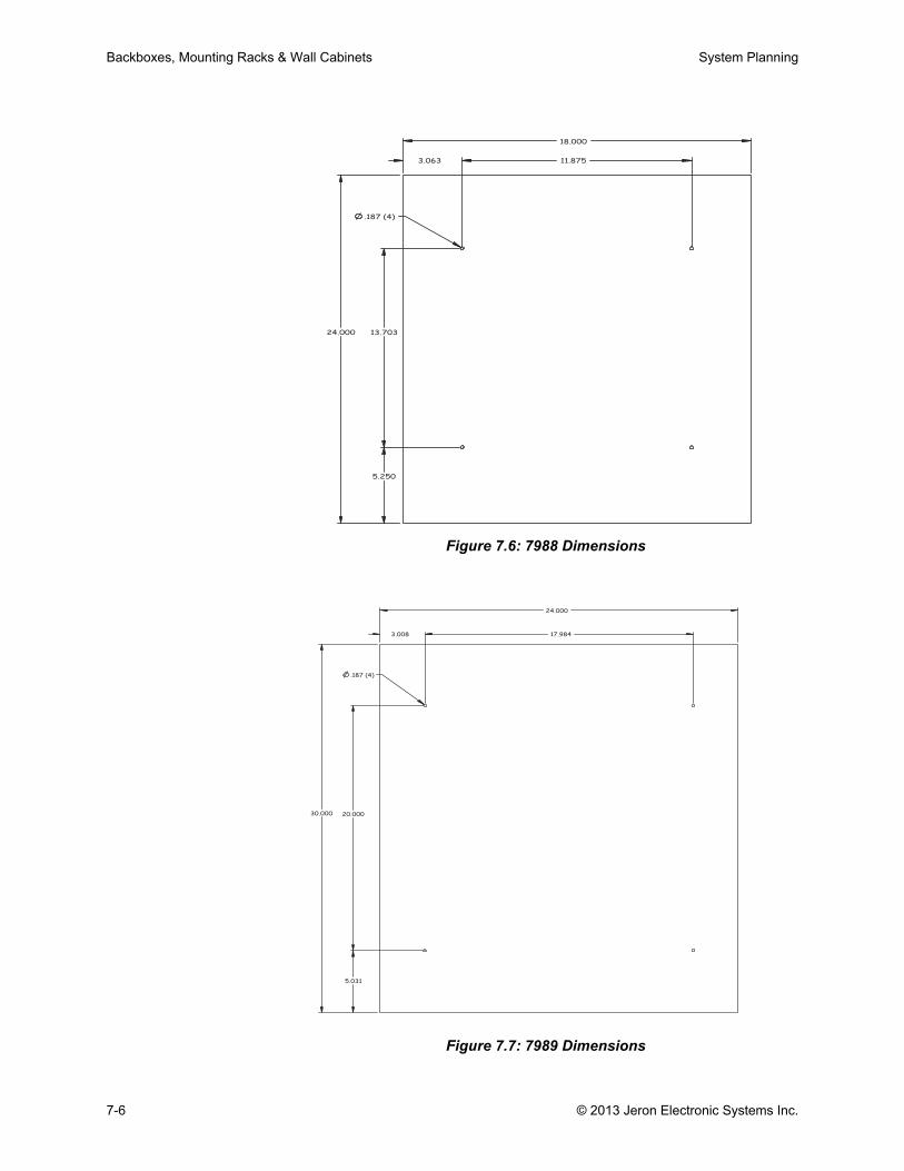
Backboxes, Mounting Racks & Wall Cabinets System Planning
Figure 7.6: 7988 Dimensions
Figure 7.7: 7989 Dimensions
11.875
13.70324.000
18.000
.187 (4)
5.250
3.063
17.984
20.00030.000
24.000
5.031
.187 (4)
3.008
7-6 © 2013 Jeron Electronic Systems Inc.
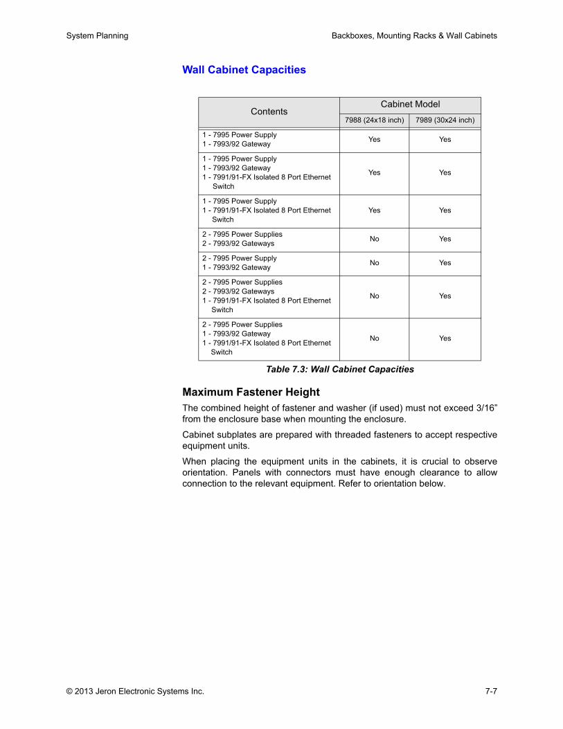
System Planning Backboxes, Mounting Racks & Wall Cabinets
Wall Cabinet Capacities
Maximum Fastener HeightThe combined height of fastener and washer (if used) must not exceed 3/16”from the enclosure base when mounting the enclosure.
Cabinet subplates are prepared with threaded fasteners to accept respectiveequipment units.
When placing the equipment units in the cabinets, it is crucial to observeorientation. Panels with connectors must have enough clearance to allowconnection to the relevant equipment. Refer to orientation below.
ContentsCabinet Model
7988 (24x18 inch) 7989 (30x24 inch)
1 - 7995 Power Supply1 - 7993/92 Gateway Yes Yes
1 - 7995 Power Supply1 - 7993/92 Gateway1 - 7991/91-FX Isolated 8 Port Ethernet
Switch
Yes Yes
1 - 7995 Power Supply1 - 7991/91-FX Isolated 8 Port Ethernet
SwitchYes Yes
2 - 7995 Power Supplies2 - 7993/92 Gateways No Yes
2 - 7995 Power Supply1 - 7993/92 Gateway No Yes
2 - 7995 Power Supplies2 - 7993/92 Gateways1 - 7991/91-FX Isolated 8 Port Ethernet
Switch
No Yes
2 - 7995 Power Supplies1 - 7993/92 Gateway1 - 7991/91-FX Isolated 8 Port Ethernet
Switch
No Yes
Table 7.3: Wall Cabinet Capacities
© 2013 Jeron Electronic Systems Inc. 7-7
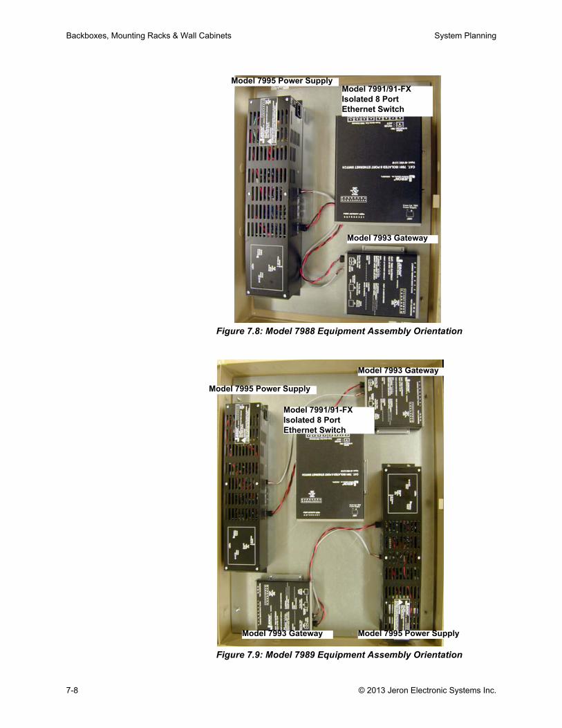
Backboxes, Mounting Racks & Wall Cabinets System Planning
Figure 7.8: Model 7988 Equipment Assembly Orientation
Figure 7.9: Model 7989 Equipment Assembly Orientation
Model 7995 Power SupplyModel 7991/91-FX Isolated 8 Port Ethernet Switch
Model 7993 Gateway
Model 7995 Power Supply
Model 7991/91-FX Isolated 8 Port Ethernet Switch
Model 7993 Gateway
Model 7993 Gateway Model 7995 Power Supply
7-8 © 2013 Jeron Electronic Systems Inc.
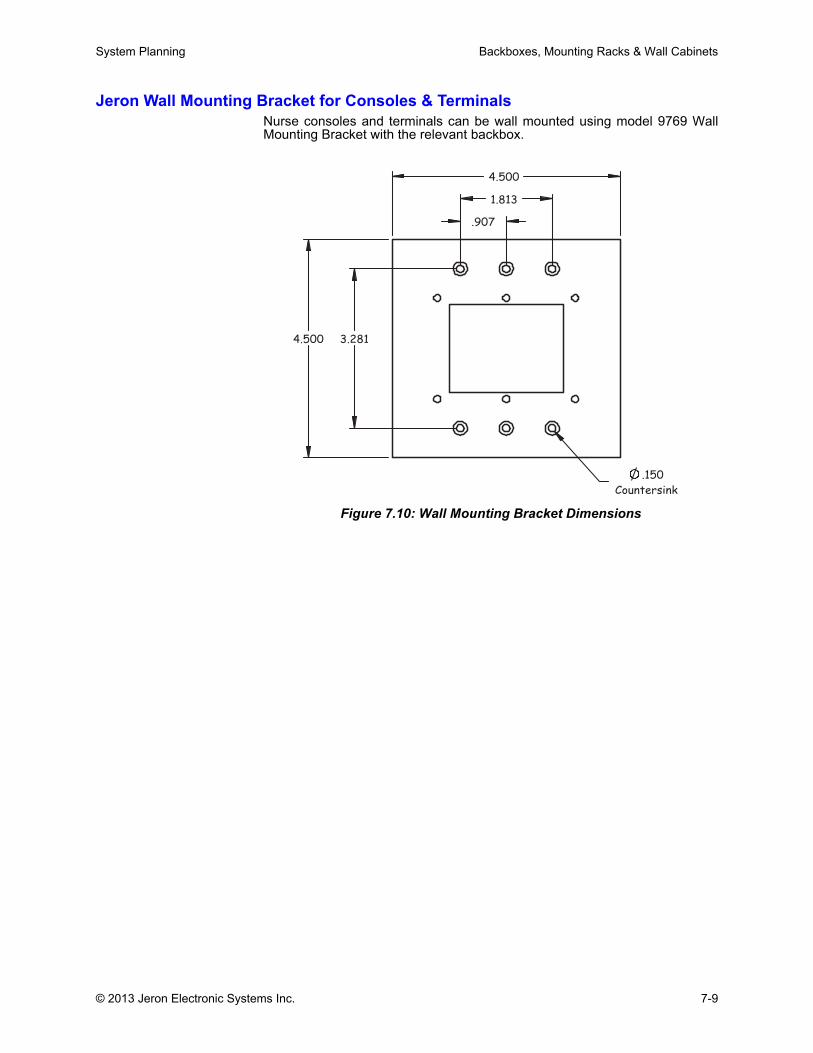
System Planning Backboxes, Mounting Racks & Wall Cabinets
Jeron Wall Mounting Bracket for Consoles & TerminalsNurse consoles and terminals can be wall mounted using model 9769 WallMounting Bracket with the relevant backbox.
Figure 7.10: Wall Mounting Bracket Dimensions
.907
1.813
3.281
4.500
4.500
.150
Countersink
© 2013 Jeron Electronic Systems Inc. 7-9

Backboxes, Mounting Racks & Wall Cabinets System Planning
7-10 © 2013 Jeron Electronic Systems Inc.

Chapter 8: Networking, Programming and Integrations

.
.

System Planning Network Overview
Network OverviewAfter installation of facility patient and staff devices, the Jeron headenddevices are connected, then networked to the facility LAN via a Bridge PC toenable the programming of the 790 system and addition of optional systemintegrations.
Provider 790 headend devices consist of the Gateways (Model 7993/2), Iso-lated 8 Port Ethernet Switches (Model 7991 or Model 7991-FX with FiberUplink option), and necessary Power Supplies (Model 7995). The compo-nents are designed for rack mounting on a standard 19" rack or wall mountingon a Jeron wall cabinet.
Each Model 7993/2 Gateway connects to the Jeron Power Supply with Bat-tery Backup (Model 7995). A supplemental power wire or an additional Model7995 Power Supply may be required.
Each Isolated 8 Port Ethernet Switch can accept connections of up to eightGateways. For more than eight Gateways in a system, multiple switches willbe used. Multiple switches in a system interconnect via their Uplink Port (port9). The main Isolated Switch also connects to the facility LAN via a Bridge PCrunning a model 7984 Bridge application.
Isolated 8 Port Ethernet Switch (with Fiber Uplink Option)Model 7991
Model 7991-FXThe Isolated 8 Port Ethernet Switch and Switch with Fiber Uplink are used tointerconnect local Nurse Call Gateways and integrate them into the entiredistributed Nurse Call Network. Utilizing industry standard network wiring,cabling, and connectors, multiple interconnected Ethernet Switches cansupport a nurse call network of up to 127 Nurse Call Gateways operating as asingle distributed system. Should the nurse call network connection be brokenat any point, the downstream Ethernet Switches and Nurse Call Gateways willcontinue to operate as a sub-system.
Up to eight Gateways can connect to one Isolated 8 Port Ethernet Switch.Distance between Gateway and 7991 switch should not exceed 328 ft.(100m). Up to 16 Switches for Gateway connections, plus an additional threeSwitches for Switch-to-Switch connections, are permitted on a single 790system. There may be no more than eight (8) Switches between any twoGateways.
To support remote and distributed Nurse Call Gateways as part of a singleNurse Call Network, the model 7991-FX Switch includes a fiber uplink portwith a duplex SC connector to support distances of up to 2 km to another7991-FX switch over dedicated 62.5/125 µm multi-mode fiber. The standard7991 and fiber enabled 7991-FX switches can be intermixed as part of thesame system.
For programming and integration purposes, a top-level switch, wired to theBridge PC interconnects the Jeron IP Network and the Hospital LAN.
© 2013 Jeron Electronic Systems Inc. 8-1
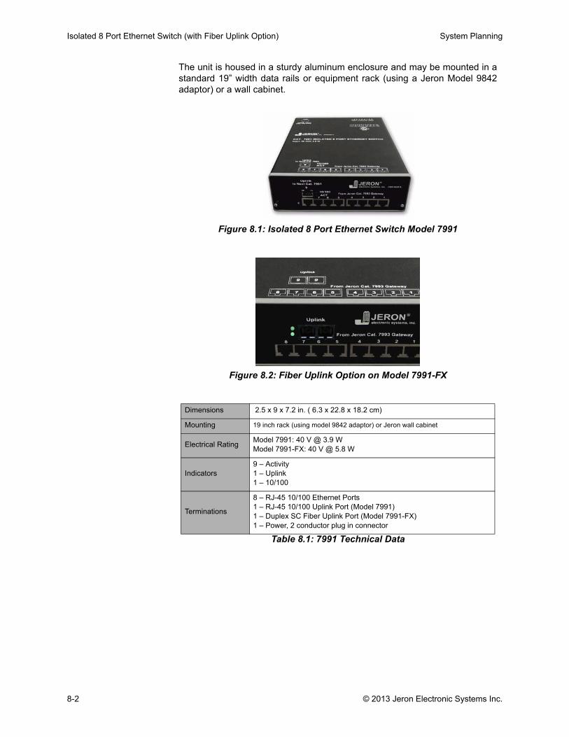
Isolated 8 Port Ethernet Switch (with Fiber Uplink Option) System Planning
The unit is housed in a sturdy aluminum enclosure and may be mounted in astandard 19” width data rails or equipment rack (using a Jeron Model 9842adaptor) or a wall cabinet.
Figure 8.1: Isolated 8 Port Ethernet Switch Model 7991
Figure 8.2: Fiber Uplink Option on Model 7991-FX
Table 8.1: 7991 Technical Data
Dimensions 2.5 x 9 x 7.2 in. ( 6.3 x 22.8 x 18.2 cm)
Mounting 19 inch rack (using model 9842 adaptor) or Jeron wall cabinet
Electrical Rating Model 7991: 40 V @ 3.9 WModel 7991-FX: 40 V @ 5.8 W
Indicators9 – Activity1 – Uplink1 – 10/100
Terminations
8 – RJ-45 10/100 Ethernet Ports1 – RJ-45 10/100 Uplink Port (Model 7991)1 – Duplex SC Fiber Uplink Port (Model 7991-FX)1 – Power, 2 conductor plug in connector
8-2 © 2013 Jeron Electronic Systems Inc.
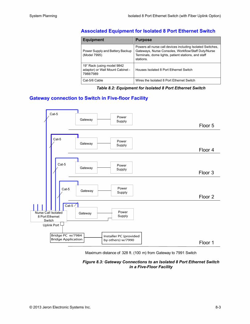
System Planning Isolated 8 Port Ethernet Switch (with Fiber Uplink Option)
Associated Equipment for Isolated 8 Port Ethernet Switch
Table 8.2: Equipment for Isolated 8 Port Ethernet Switch
Gateway connection to Switch in Five-floor Facility
Figure 8.3: Gateway Connections to an Isolated 8 Port Ethernet Switch in a Five-Floor Facility
Equipment Purpose
Power Supply and Battery Backup (Model 7995)
Powers all nurse call devices including Isolated Switches, Gateways, Nurse Consoles, Workflow/Staff Duty/Nurse Terminals, dome lights, patient stations, and staff stations.
19” Rack (using model 9842 adaptor) or Wall Mount Cabinet - 7988/7989
Houses Isolated 8 Port Ethernet Switch
Cat-5/6 Cable Wires the Isolated 8 Port Ethernet Switch
Floor 1
Floor 2
Floor 3
Floor 4
Floor 5
Nurse Call Isolated
8 Port Ethernet
Switch
Gateway
Maximum distance of 328 ft. (100 m) from Gateway to 7991 Switch
Power
Supply
GatewayPower
Supply
GatewayPower
Supply
GatewayPower
Supply
Uplink Port
Cat-5
Cat-5
Cat-5
Cat-5
Power
SupplyGateway
Cat-5
Bridge PC w/7984Bridge Application
Installer PC (providedby others) w/7990
© 2013 Jeron Electronic Systems Inc. 8-3
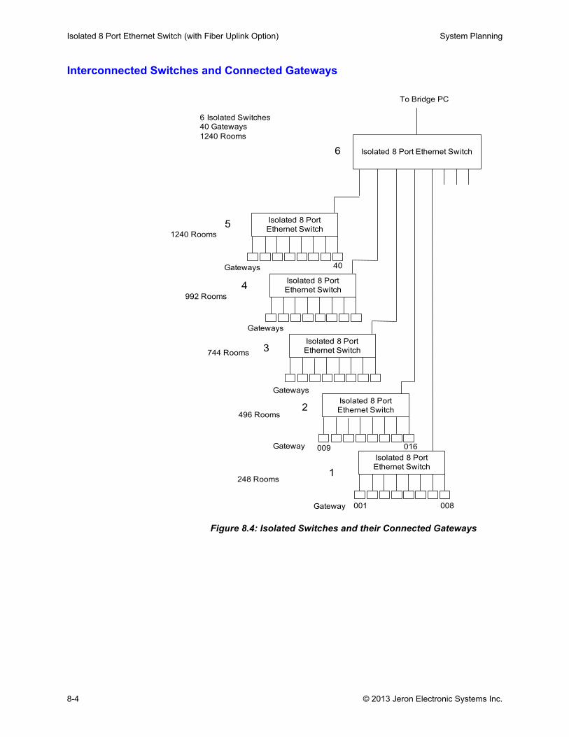
Isolated 8 Port Ethernet Switch (with Fiber Uplink Option) System Planning
Interconnected Switches and Connected Gateways
Figure 8.4: Isolated Switches and their Connected Gateways
Isolated 8 Port Ethernet Switch
Isolated 8 Port
Ethernet Switch
Gateway
Isolated 8 Port
Ethernet Switch
Isolated 8 Port
Ethernet Switch
Isolated 8 Port
Ethernet Switch
Isolated 8 Port
Ethernet Switch
Gateway
Gateways
Gateways
Gateways
1
2
3
4
5
001
40
008
009 016
To Bridge PC
248 Rooms
496 Rooms
744 Rooms
992 Rooms
1240 Rooms
6 Isolated Switches
40 Gateways
1240 Rooms
6
8-4 © 2013 Jeron Electronic Systems Inc.
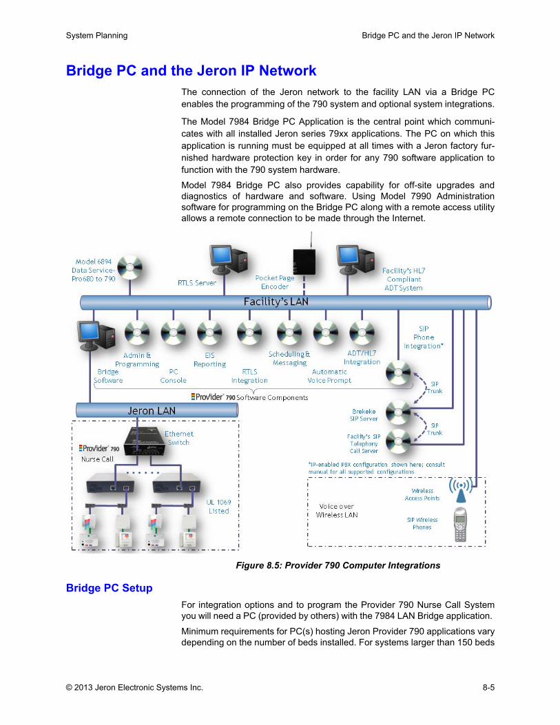
System Planning Bridge PC and the Jeron IP Network
Bridge PC and the Jeron IP NetworkThe connection of the Jeron network to the facility LAN via a Bridge PCenables the programming of the 790 system and optional system integrations.
The Model 7984 Bridge PC Application is the central point which communi-cates with all installed Jeron series 79xx applications. The PC on which thisapplication is running must be equipped at all times with a Jeron factory fur-nished hardware protection key in order for any 790 software application tofunction with the 790 system hardware.
Model 7984 Bridge PC also provides capability for off-site upgrades anddiagnostics of hardware and software. Using Model 7990 Administrationsoftware for programming on the Bridge PC along with a remote access utilityallows a remote connection to be made through the Internet.
Figure 8.5: Provider 790 Computer Integrations
Bridge PC SetupFor integration options and to program the Provider 790 Nurse Call Systemyou will need a PC (provided by others) with the 7984 LAN Bridge application.
Minimum requirements for PC(s) hosting Jeron Provider 790 applications varydepending on the number of beds installed. For systems larger than 150 beds
© 2013 Jeron Electronic Systems Inc. 8-5
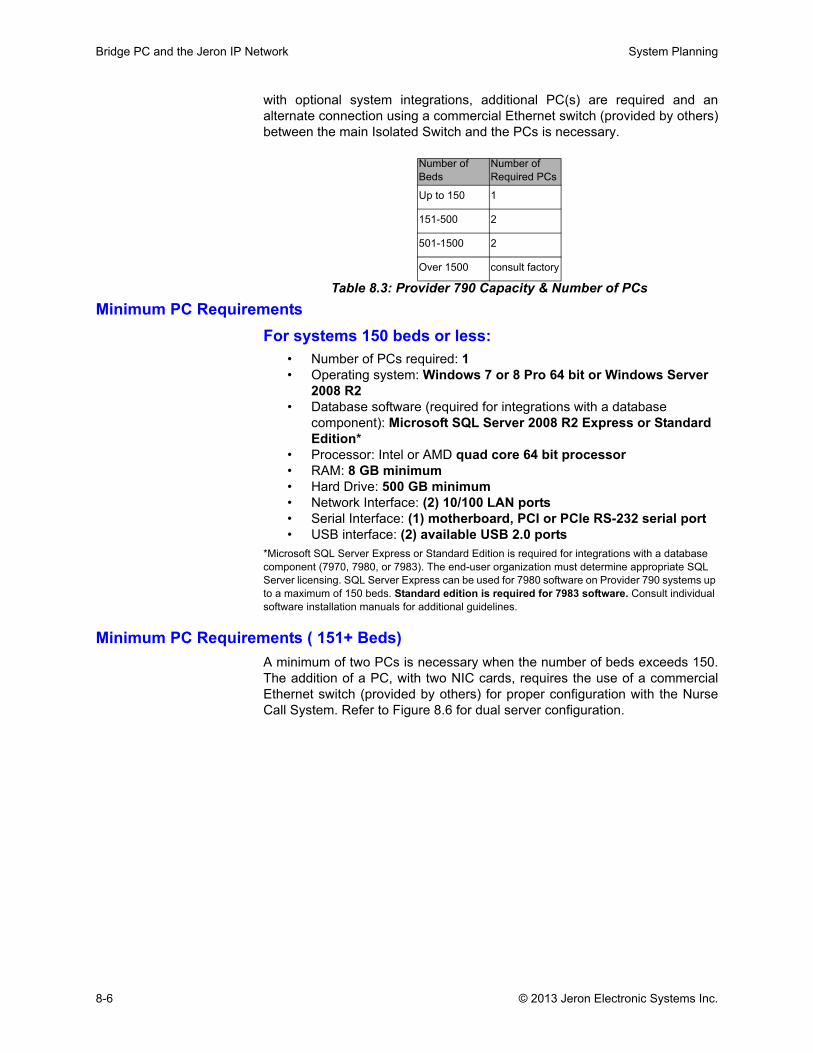
Bridge PC and the Jeron IP Network System Planning
with optional system integrations, additional PC(s) are required and analternate connection using a commercial Ethernet switch (provided by others)between the main Isolated Switch and the PCs is necessary.
Minimum PC RequirementsFor systems 150 beds or less:
• Number of PCs required: 1• Operating system: Windows 7 or 8 Pro 64 bit or Windows Server
2008 R2• Database software (required for integrations with a database
component): Microsoft SQL Server 2008 R2 Express or Standard Edition*
• Processor: Intel or AMD quad core 64 bit processor• RAM: 8 GB minimum• Hard Drive: 500 GB minimum• Network Interface: (2) 10/100 LAN ports• Serial Interface: (1) motherboard, PCI or PCIe RS-232 serial port• USB interface: (2) available USB 2.0 ports
*Microsoft SQL Server Express or Standard Edition is required for integrations with a database component (7970, 7980, or 7983). The end-user organization must determine appropriate SQL Server licensing. SQL Server Express can be used for 7980 software on Provider 790 systems up to a maximum of 150 beds. Standard edition is required for 7983 software. Consult individual software installation manuals for additional guidelines.
Minimum PC Requirements ( 151+ Beds)A minimum of two PCs is necessary when the number of beds exceeds 150.The addition of a PC, with two NIC cards, requires the use of a commercialEthernet switch (provided by others) for proper configuration with the NurseCall System. Refer to Figure 8.6 for dual server configuration.
Table 8.3: Provider 790 Capacity & Number of PCs
Number of Beds
Number of Required PCs
Up to 150 1
151-500 2
501-1500 2
Over 1500 consult factory
8-6 © 2013 Jeron Electronic Systems Inc.
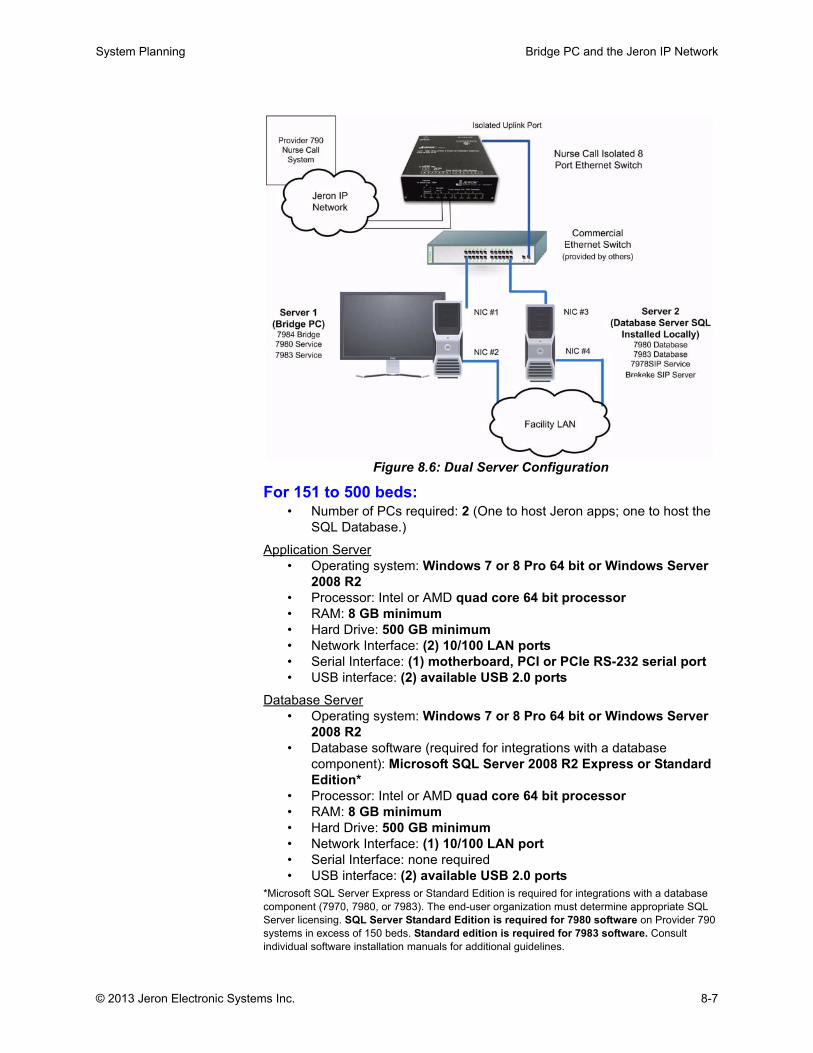
System Planning Bridge PC and the Jeron IP Network
Figure 8.6: Dual Server Configuration
For 151 to 500 beds:• Number of PCs required: 2 (One to host Jeron apps; one to host the
SQL Database.)
Application Server• Operating system: Windows 7 or 8 Pro 64 bit or Windows Server
2008 R2• Processor: Intel or AMD quad core 64 bit processor• RAM: 8 GB minimum• Hard Drive: 500 GB minimum• Network Interface: (2) 10/100 LAN ports• Serial Interface: (1) motherboard, PCI or PCIe RS-232 serial port• USB interface: (2) available USB 2.0 ports
Database Server• Operating system: Windows 7 or 8 Pro 64 bit or Windows Server
2008 R2• Database software (required for integrations with a database
component): Microsoft SQL Server 2008 R2 Express or Standard Edition*
• Processor: Intel or AMD quad core 64 bit processor• RAM: 8 GB minimum• Hard Drive: 500 GB minimum• Network Interface: (1) 10/100 LAN port• Serial Interface: none required• USB interface: (2) available USB 2.0 ports
*Microsoft SQL Server Express or Standard Edition is required for integrations with a database component (7970, 7980, or 7983). The end-user organization must determine appropriate SQL Server licensing. SQL Server Standard Edition is required for 7980 software on Provider 790 systems in excess of 150 beds. Standard edition is required for 7983 software. Consult individual software installation manuals for additional guidelines.
© 2013 Jeron Electronic Systems Inc. 8-7
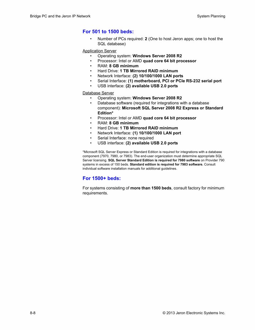
Bridge PC and the Jeron IP Network System Planning
For 501 to 1500 beds:• Number of PCs required: 2 (One to host Jeron apps; one to host the
SQL database)
Application Server• Operating system: Windows Server 2008 R2• Processor: Intel or AMD quad core 64 bit processor• RAM: 8 GB minimum• Hard Drive: 1 TB Mirrored RAID minimum• Network Interface: (2) 10/100/1000 LAN ports• Serial Interface: (1) motherboard, PCI or PCIe RS-232 serial port• USB interface: (2) available USB 2.0 ports
Database Server• Operating system: Windows Server 2008 R2• Database software (required for integrations with a database
component): Microsoft SQL Server 2008 R2 Express or Standard Edition*
• Processor: Intel or AMD quad core 64 bit processor• RAM: 8 GB minimum• Hard Drive: 1 TB Mirrored RAID minimum• Network Interface: (1) 10/100/1000 LAN port• Serial Interface: none required• USB interface: (2) available USB 2.0 ports
*Microsoft SQL Server Express or Standard Edition is required for integrations with a database component (7970, 7980, or 7983). The end-user organization must determine appropriate SQL Server licensing. SQL Server Standard Edition is required for 7980 software on Provider 790 systems in excess of 150 beds. Standard edition is required for 7983 software. Consult individual software installation manuals for additional guidelines.
For 1500+ beds:
For systems consisting of more than 1500 beds, consult factory for minimum requirements.
8-8 © 2013 Jeron Electronic Systems Inc.

System Planning Required Software Applications
Required Software ApplicationsModel 7984 Bridge Software Application
The Jeron Model 7984 Bridge Software Application is used with the Provider790 Nurse Call System to connect the nurse call to the facility's LAN and inturn other optional Provider 790 software applications residing on the LAN.The 7984 Bridge is linked to the Provider 790 Nurse Call System through theisolated port on the UL1069 Listed Model 7991 Ethernet Switch.
The PC running the 7984 Bridge Software must be equipped with two NICs(Network Interface Cards). The Bridge software acts as a data firewallisolating each operating Gateway (the Jeron IP Network) connected toNetwork Interface Card #1 on the Bridge PC and any other device such asclient PCs on the Hospital LAN connected to Network Interface #2. It blocksall other LAN activity from the nurse call system.
Using TCP/IP, the 7984 software provides a secure data connection to theProvider 790 software applications on the LAN. The 7984 software also readsthe LAN NTP (Network Time Protocol) and relays this time to the Provider 790Nurse Call System so that both the nurse call and facility LAN share the sametime base. Through 7984, technicians on any PC on the facility's LAN runningthe Provider 790 7990 Administration Software have remote access to theentire nurse call system for programming, firmware updates, andtroubleshooting.
Model 7990 Administration SoftwareThe Jeron Model 7990 Administration and Programming Software is used toprogram and administer the Provider 790 Nurse Call System through the7984 Bridge Software and associated Bridge PC. The 7990 software allows atechnician to program and manage all system attributes including roomnumbers, call priorities, call tones, dome light indications, swing rooms, andcoverage of duty stations, zone lights, Workflow/Staff Duty/Nurse Terminals,and Nurse Consoles. With 7990, the Provider 790 system may be configured,downloaded (for archiving), restored, and edited without affecting the localoperation of the nurse call system.
The 7990 software also supports firmware updates for all nurse call hardwaredevices including Gateways, Controllers, Nurse Consoles, and Terminals.
Gateways must be programmed with a unique IP address and location nameprior to wiring on the J Bus. Refer to Installation & Programming Manual forinstruction.
Programming System Configuration
Below is an overview of the programming process with 7990 AdministrationSoftware. Refer to the Provider 790 Installation & Programming Manual fordetails:
• Stations, terminals and consoles are wired to a Controller and sharethe Controllers’ room name (ID). The Controller comes with a defaultID that can be changed in programming to reflect the location of thedevices/room. After Controllers have been identified and assigned alocation-specific name, a visual diagram of the facility is created. The
© 2013 Jeron Electronic Systems Inc. 8-9
Required Software Applications System Planning
diagram consists of buildings, floors, units and coverage areas. Thereshould be a minimum one coverage area per unit.
• Floors and Units: A Gateway would be utilized on a single floor, andmay cover all or some of the rooms on a certain floor. A unit mayrequire more than one Gateway if the unit exceeds the number ofsupported rooms (max 31). In that case, multiple Gateways will beused on the floor. One Gateway may be sufficient for multiple units ona floor if the units are small and do not exceed the 31 room limit or the700 foot J Bus limit.
• Coverage Areas: Coverage area(s) include rooms within a unit thatare covered by a specific Nurse Console. A unit may contain onecoverage area (i.e., all rooms assigned to a Nurse Console) ormultiple coverage areas (where rooms are assigned to multiple NurseConsoles). Typically, rooms in a unit are physically located in thesame part of the facility, (i.e., the same floor or wing). Each room isassigned to a coverage area by adding stations and Consoles/Terminals to the facility diagram in 7990. This determines the rooms/areas that report to and annunciate calls to a particular NurseConsole. Refer to Figure 8.7.
• Duty Areas: Room stations, Model 7917 Visual Duty, and Model7927 Staff/Duty are assigned to duty areas. Model 7967-S Staff DutyTerminals are programmed to show active calls within its assignedcoverage area, with calls grouped by Routine, Urgent, Emergency,and Code. Duty stations respond simultaneously and identically tocalls from room stations programmed to report to the duty area.
• Zone Areas: Room stations and Zone Lights are assigned to zoneareas. Zone Lights respond simultaneously and identically to callsfrom room stations programmed to report to the zone area.
Note: All rooms report to all Nurse Consoles by default. The assignment to coverageareas is done in programming.
8-10 © 2013 Jeron Electronic Systems Inc.
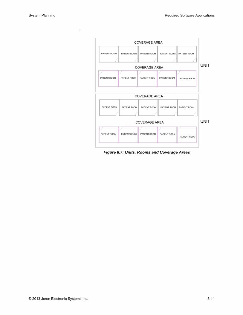
System Planning Required Software Applications
.
Figure 8.7: Units, Rooms and Coverage Areas
COVERAGE AREA
COVERAGE AREAUNIT
PATIENT ROOM PATIENT ROOM PATIENT ROOM PATIENT ROOM PATIENT ROOM
PATIENT ROOMPATIENT ROOMPATIENT ROOMPATIENT ROOMPATIENT ROOM
COVERAGE AREA
COVERAGE AREA UNIT
PATIENT ROOM PATIENT ROOM PATIENT ROOM PATIENT ROOM PATIENT ROOM
PATIENT ROOM
PATIENT ROOMPATIENT ROOMPATIENT ROOMPATIENT ROOM
© 2013 Jeron Electronic Systems Inc. 8-11
Optional Software Integrations System Planning
Optional Software IntegrationsThe Model 7984 Bridge PC Application communicates with all installed Jeronseries 79xx optional integrations. For any optional integration to function withthe 790 system hardware, the installation PC must be equipped at all timeswith a Jeron factory furnished hardware protection key.The optional integrations available in Provider 790 are as follows:
• Model 7970 Automatic Voice Prompt Software• Model 7977 ADT Patient Information Application• Model 7978SIP SIP Phone Integration Software• Model 7980 Staff Assignment & Messaging Software• Model 7981 RTLS Integration Software• Model 7983 EIS Activity Logging & Reporting Software• Model 7985 PC Console Software• Model 7986 Map Configuration Software• Model 6894 Integration Data Service
The installation and use of these applications are covered in the Provider 790Advanced Training class.
Bridge PC System Requirements
Use of optional integrations requires presence of the following systemcomponents on the Bridge PC:
• Microsoft .NET 4.0 Framework, both Client and Extended versions.Refer to integration installation manual for further instruction
• Windows IIS Web Server 7.5
• Microsoft SQL Server 2008 R2 Express or Standard Edition*
• Use Internet Explorer 8 or greater to run browser-based interface forapplications
*Microsoft SQL Server Express or Standard Edition is required for integrations with a databasecomponent (7970, 7980, or 7983). The end-user organization must determine appropriate SQLServer licensing. SQL Server Express can be used for 7980 software on Provider 790 systems upto a maximum of 150 beds. Standard edition is required for 7983 software.
For minimum requirements of the installation PC(s) hosting Provider 790integrations, refer to page 8-6. Integrations that incorporate access to clientsoftware components on a networked facility PC must adhere to additionalminimum requirements.
Minimum Client PC RequirementsThe following minimum hardware, software, and operating systemrequirements apply to the networked facility PC(s) used to access the clientsoftware component of Model 7980 Staff Assignment & Messaging Software,the browser-based interface of Model 7983 EIS Activity Logging & ReportingSoftware, or the client software component of Model 7985 PC Console:
• 1 GHz or faster 32-bit (x86) or 64-bit (x64) processor• Windows XP Pro or Windows 7 Pro, 32 or 64 bit• 1 GB RAM (32-bit) or 2 GB RAM (64-bit)• One (1) 10/100 LAN Port
8-12 © 2013 Jeron Electronic Systems Inc.
System Planning Optional Software Integrations
• .NET 4.0 Framework, both Client and Extended versions. Refer tointegration installation manual for further instruction
• Use Internet Explorer 8 or greater to run browser-based interface forapplications
The following is a brief overview of the available Provider 790 integrations foradded functionality and support of popular third-party equipment andapplications:
Model 7970 Automatic Voice Prompt SoftwareProvides verbal annunciation of select Provider 790 Nurse Call System callevents over a facility's overhead paging system. Pages are triggered by nursecalls placed or cancelled from patient rooms or staff stations. Voice promptsconsist of phrases that include instructional content as well as call type androom location information. Voice prompts can be customized on-site to meetfacility requirements for privacy and content. For example: A code call in room206 annunciates "Stat condition in second floor physical therapy." Uponcancellation: "Medical condition in physical therapy has been cancelled."7970 requires Model 9815-1 single channel USB Zone Control, or 9815-2eight channel USB Zone Control with optional 9815-3 USB Mute Contact.
This integration requires Microsoft SQL Server. Refer to ‘Minimum PC Requirements” on page 8-6 for more information.
Model 7977 ADT Patient Information Integration SoftwareThe Jeron Model 7977 ADT Patient Information Integration Software is usedwith the Provider 790 Nurse Call System to integrate with the facility's ADTsystem for automated update of patient information displayed at nurseconsoles/terminals, PC consoles, and staff duty terminals.
When patient information and assigned bed information are updated on theADT system, the 7977 listens for updates over the HL7 protocol standard andautomatically sends this information to the Provider 790 Nurse Call System todisplay the information when a patient places a call. The patient information isdisplayed at Jeron model 7965 Nurse Console, 7967 Staff Duty/NurseTerminal and 7985 PC Console Application.
When the integration software is configured, the installer can determine whichADT information fields are mapped to the nurse call system including: patientname, doctor, and up to several fields of patient information. Alternately,during configuration, key ADT information fields may be blocked from beingdisplayed on the nurse call system. To ensure compliance with HIPAA patientconfidentiality requirements, the patient information is stored securely withinthe nurse call system and is only displayed at Nurse Consoles, PC Consoles,and Staff Duty or Nurse Terminals within staff areas.
Model 7978SIP SIP Phone Integration SoftwareThe Jeron Model 7978SIP SIP Phone Integration Software is used with theProvider 790 Nurse Call System to route patient calls on the nurse call LAN.Through the intermediary Brekeke SIP Server, the SIP phone call is routed tothe facility’s SIP Telephony Call Server and in turn over the facility’s Voiceover Wireless LAN to the SIP end device carried by the assigned caregiver.
© 2013 Jeron Electronic Systems Inc. 8-13
Optional Software Integrations System Planning
The 7978SIP routes calls based on the patient-to-staff and staff-to-deviceassignments programmed into the Jeron Model 7980 Assignment Software.
From their SIP wireless phones, caregivers can also call into any staffintercom or patient intercom station on the Provider 790 nurse call system.
Each J Bus with patient intercom stations has eight simultaneous full duplex audio circuits which provides non-blocking service for multiple SIP phones calling to the same J Bus.
Model 7980 Staff Assignment & Messaging SoftwareThe Jeron Model 7980 Staff Assignment and Messaging Software is used tomanage mobile locating and notification devices for the Provider 790 NurseCall System. Through this software, system administrators, technicians, andcharge nurses manage all wireless devices, staff member attributes, staff todevice assignments, staff to patient assignments, and staff to teamassignments. The software itself sends messages over TAP protocol directlyto paging encoders or wireless phone middleware. In addition to the 7980software, integration for wireless phone communication and real time locatingtags requires integration software and/or hardware from Jeron.
For the end-user, access to the software is .NET browser-based allowingusers to sign on from any PC on the LAN. Based on their account security,users can do the following:
• Configure system wide settings including name format, call response timers, pager cancellation messages
• Add/edit mobile locating and notification devices including wireless phones, pocket pagers, and real time locating tags
• Manage signon access levels and access to functions and nursing units
• Create and assign staff to facility-wide crash teams, such as code crash teams, and local emergency all call teams
• Manage the association of staff and devices to one, several, or all units within the facility
• For each of up to three shifts per unit per day, assign from one to three team members to each patient room/bed for notification plus a unit level backup
• Configure notification to technician(s) phone/pager for instant alerting of any component failures
This integration requires Microsoft SQL Server. Refer to ‘Minimum PC Requirements” on page 8-6 for more information.
Model 7981 RTLS Integration Software The Jeron Model 7981 RTLS (Real Time Locating System) IntegrationSoftware is used with the Provider 790 Nurse Call System to integrate withthe facility's RTLS server for automated staff locating. The 7981 provides asingle point of connection between the RTLS server and the Provider 790system and supports the most popular locating systems on the market.
The RTLS automated staff location integration provides the followingfunctionality on the nurse call system:
8-14 © 2013 Jeron Electronic Systems Inc.
System Planning Optional Software Integrations
• Automatic registration of staff in and out of patient rooms
• Dome light indication of staff present in each room (green, orange, or yellow)
• Automatic cancellation of outstanding service requirements by staff with locating tags walking into the patient room
• Locate staff by level and name from any Nurse Console/Terminal or Staff Duty Terminal with one-touch to communicate with staff via the closest intercom station
The 7981 is used in conjunction with the Jeron Model 7980 Staff AssignmentSoftware which associates the locating tag with a specific staff member andtheir registration level (green, orange, or yellow). If the staff tag is equippedwith a call button, when the button is pressed while in a patient room it willplace a predetermined call priority level from that room.
Model 7983 EIS Log ReportThe Jeron Model 7983 Executive Information System (EIS) Software Packageis used with the Provider 790 Nurse Call System for archiving and analysisreports of patient call and staff response activity. All nurse call activity data,including patient and staff calls, staff registration, voice response time, staffresponse time, and system supervision messages are logged in a SQLdatabase.
From any PC on the facility's LAN, through the browser interface, staff cansign in and generate standard and customized reports for a single unit, acombination of units, or the entire facility. The staff member's signonprivileges determine which unit(s) and types of reports they can generate.Reports are produced in a standard PDF format allowing for easy printing.Email feature allows for the scheduling and automatic delivery of futurereports.
This integration requires Microsoft SQL Server. Refer to ‘Minimum PCRequirements” on page 8-6 for more information.
Model 7985 PC Console SoftwareModel 7986 Map Configuration Software
Accessible via any PC on the facility's LAN, the Jeron Model 7985 PCConsole Software is used with the Provider 790 Nurse Call System for a real-time view of nurse call activity and to initiate/review staff roundings. The clientsoftware component of the 7985 application resides on non-dedicatedWindows® computers and communicates via TCP/IP to the server componentto ensure only authorized staff have access to nurse call activity. Multipleusers can simultaneously run local 7985 software on their own PCs; each withtheir own view of nurse call activity. The architecture of the 7985 software andthe Provider 790 Nurse Call System precludes any activity on the LAN fromadversely affecting the life safety operation of the Provider 790 Nurse CallSystem.
The software supports three views: List, Whiteboard, and Map.
List view displays active events including patient and staff calls, overtimeservice requests, expired roundings and self-reminders, and active work flowevents. The nurse call activity displayed in list view can be independent or
Note: When operating in Associated Mode, each Model 7965 Nurse Console can only be associated with a single Model 7985 PC Console client PC.
© 2013 Jeron Electronic Systems Inc. 8-15
Optional Software Integrations System Planning
associated with the operation of a specific Model 7965 Nurse Console. In theindependent display mode, the software can be customized by coverage area(one unit, several units, or the entire facility), by call priorities to display (one,several, or all), to display service requirements or not, to display work flowevents (one, several, or all), to display staff locations or not, and to displaystaff roundings or not. When associated with a nurse console, the softwarewill show all call activity based on the console's coverage.
Whiteboard view lists all rooms/beds and associated information (patientinformation and assigned staff), active call events, staff presence, roundings,self-reminders, Stryker® iBed Awareness status, and/or workflow events forthe selected nursing unit. The display of patient information also requires theaddition of the Jeron 7977 ADT Patient Information Integration Software.
Map view displays events and activity associated with each room (includingactive calls) on a graphical floor layout for the selected nursing unit. For eachunit, the map view supports the display of up to 192 rooms on up to four viewstotal. The map view automatically switches to the map with the highest priorityactive call. Map view requires optional 7986 Map Configuration Software.
The 7985 also allows nurse managers from any networked PC to set andreview existing roundings or one time reminders on a per patient bed basis.From any networked PC, when used in conjunction with the required Jeron7980 Staff Assignment & Messaging Software, the 7985 also allowsadministrators and staff to send text message to the wireless phone or pagercarried by specific staff members or to send group messages to caregiver'sphones and/or pagers.
Model 6894 Integration Data Service Achieves platform inter-operability between Provider 680 and Provider 790systems for improved communication and analysis of nurse call activity in asingle facility. An integrated communication system gives staff and caregiversgreater flexibility to observe, respond to, and analyze all system activity fromany PC on the facility LAN.
The Integration Data Service transmits configuration and call information fromProvider 680 systems directly to the 7984 Bridge PC application. Informationis disseminated directly from the Bridge application to the following systemintegrations:
• Model 7970 Automatic Voice Prompt Software for verbalannunciation of nurse call events on facility’s overhead pagingsystem
• Model 7980 Staff Assignment & Messaging Software for appropriatecall routing to caregiver device
• Model 7983 Executive Information System (EIS) Software forarchiving and analysis reports of call activity
• Model 7985 PC Console for a real-time view of nurse call activity
The 6894 service tool centralizes nurse call operation by combining attributesof both Provider platforms. System configurations are integrated byassociating 680 controllers and coverage areas to new units in the 790system (if present), and associating 680 call types with 790 equivalents. Thetool then produces a single architectural diagram configuration file used totransmit global configuration via Model 7990 Administration Software. All
Note: 7985 map view requires optional model 7986 Map Configuration Software.
8-16 © 2013 Jeron Electronic Systems Inc.

System Planning Optional Software Integrations
connections and data transmissions are performed without affecting the localoperation of the nurse call systems.
© 2013 Jeron Electronic Systems Inc. 8-17

Optional Software Integrations System Planning
8-18 © 2013 Jeron Electronic Systems Inc.