scott bookcase 120413
DESCRIPTION
Instructions for building a large painted bookcase.TRANSCRIPT

You Can Build the Scott Bookcase By Jeff Branch
THE GOAL WITH this bookcase was to make something which fit a large size requirement and to make it as easily as possible. When this bookcase was constructed, I had just completed a sizeable project and was not really wanting to tackle yet another large piece of furniture with an equally large time commitment. To make this bookcase as simple as possible, I painted it which allowed me to make it from birch plywood, poplar, MDF and stock pine moldings. In addition, being painted meant I did not have to fuss with grain matching and working around minor wood defects. To make the project more manageable, the bookcase was built in two sections. For my small basement workshop, two smaller sections work better than one big bookcase. This two section format enabled me to try out some design ideas that had been
floating around in my head for a while. First, the upper case is significantly more narrow than the base cabinet. I had seen a similar design for a hutch and had liked it. Second, I was able to incorporate a variety of moldings to dress up the piece. Note the simulated side panels with inset stop molding, the heavy base board, waist moldings and the large crown at the top. The size requested was five feet wide and seven feet tall. In an effort to minimize waste, I suggested a four foot wide bookcase, but five feet was a requirement from the client. The bookcase was painted by hand. I realized from this project the need for spray equipment which would have further simplified the build process for this large piece of furniture.
Jeff Branch WOODWORKING

Main Dimensions
2
© 2013 by Jeff Branch
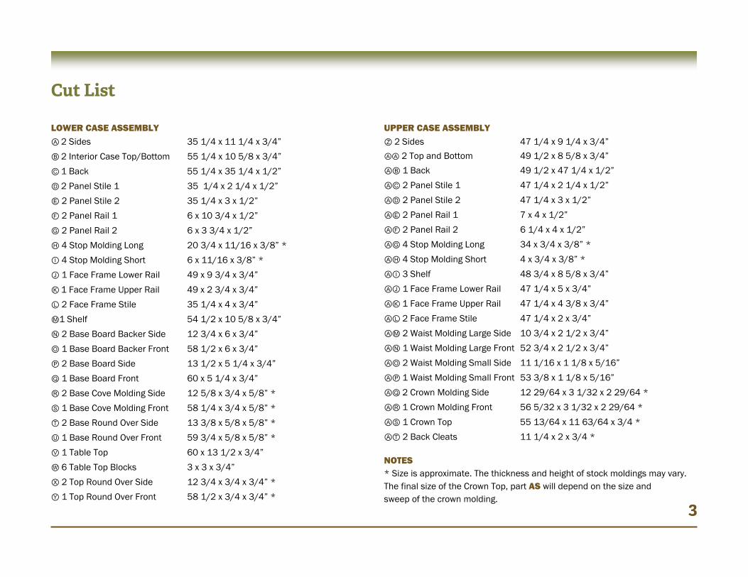
LOWER CASE ASSEMBLY Ⓐ 2 Sides 35 1/4 x 11 1/4 x 3/4”
Ⓑ 2 Interior Case Top/Bottom 55 1/4 x 10 5/8 x 3/4”
Ⓒ 1 Back 55 1/4 x 35 1/4 x 1/2”
Ⓓ 2 Panel Stile 1 35 1/4 x 2 1/4 x 1/2”
Ⓔ 2 Panel Stile 2 35 1/4 x 3 x 1/2”
Ⓕ 2 Panel Rail 1 6 x 10 3/4 x 1/2”
Ⓖ 2 Panel Rail 2 6 x 3 3/4 x 1/2”
Ⓗ 4 Stop Molding Long 20 3/4 x 11/16 x 3/8” *
Ⓘ 4 Stop Molding Short 6 x 11/16 x 3/8” *
Ⓙ 1 Face Frame Lower Rail 49 x 9 3/4 x 3/4”
Ⓚ 1 Face Frame Upper Rail 49 x 2 3/4 x 3/4”
Ⓛ 2 Face Frame Stile 35 1/4 x 4 x 3/4”
Ⓜ1 Shelf 54 1/2 x 10 5/8 x 3/4”
Ⓝ 2 Base Board Backer Side 12 3/4 x 6 x 3/4”
Ⓞ 1 Base Board Backer Front 58 1/2 x 6 x 3/4”
Ⓟ 2 Base Board Side 13 1/2 x 5 1/4 x 3/4”
Ⓠ 1 Base Board Front 60 x 5 1/4 x 3/4”
Ⓡ 2 Base Cove Molding Side 12 5/8 x 3/4 x 5/8” *
Ⓢ 1 Base Cove Molding Front 58 1/4 x 3/4 x 5/8” *
Ⓣ 2 Base Round Over Side 13 3/8 x 5/8 x 5/8” * Ⓤ 1 Base Round Over Front 59 3/4 x 5/8 x 5/8” *
Ⓥ 1 Table Top 60 x 13 1/2 x 3/4”
Ⓦ 6 Table Top Blocks 3 x 3 x 3/4” Ⓧ 2 Top Round Over Side 12 3/4 x 3/4 x 3/4” *
Ⓨ 1 Top Round Over Front 58 1/2 x 3/4 x 3/4” *
UPPER CASE ASSEMBLY Ⓩ 2 Sides 47 1/4 x 9 1/4 x 3/4”
ⒶⒶ 2 Top and Bottom 49 1/2 x 8 5/8 x 3/4”
ⒶⒷ 1 Back 49 1/2 x 47 1/4 x 1/2”
ⒶⒸ 2 Panel Stile 1 47 1/4 x 2 1/4 x 1/2”
ⒶⒹ 2 Panel Stile 2 47 1/4 x 3 x 1/2”
ⒶⒺ 2 Panel Rail 1 7 x 4 x 1/2”
ⒶⒻ 2 Panel Rail 2 6 1/4 x 4 x 1/2”
ⒶⒼ 4 Stop Molding Long 34 x 3/4 x 3/8” *
ⒶⒽ 4 Stop Molding Short 4 x 3/4 x 3/8” *
ⒶⒾ 3 Shelf 48 3/4 x 8 5/8 x 3/4”
ⒶⒿ 1 Face Frame Lower Rail 47 1/4 x 5 x 3/4”
ⒶⓀ 1 Face Frame Upper Rail 47 1/4 x 4 3/8 x 3/4”
ⒶⓁ 2 Face Frame Stile 47 1/4 x 2 x 3/4”
ⒶⓂ 2 Waist Molding Large Side 10 3/4 x 2 1/2 x 3/4”
ⒶⓃ 1 Waist Molding Large Front 52 3/4 x 2 1/2 x 3/4”
ⒶⓄ 2 Waist Molding Small Side 11 1/16 x 1 1/8 x 5/16”
ⒶⓅ 1 Waist Molding Small Front 53 3/8 x 1 1/8 x 5/16”
ⒶⓆ 2 Crown Molding Side 12 29/64 x 3 1/32 x 2 29/64 *
ⒶⓇ 1 Crown Molding Front 56 5/32 x 3 1/32 x 2 29/64 *
ⒶⓈ 1 Crown Top 55 13/64 x 11 63/64 x 3/4 *
ⒶⓉ 2 Back Cleats 11 1/4 x 2 x 3/4 * NOTES * Size is approximate. The thickness and height of stock moldings may vary. The final size of the Crown Top, part AS will depend on the size and sweep of the crown molding.
Cut List
3

Build the Lower Case
Ⓐ
BEGIN CONSTRUCTION BY cutting the lower case sides, parts A, to final size (see the cut list). Form two dados and a rabbet as indicated in 4a. Drill shelf support holes as shown. Cut parts B following the cut list. Add glue to the dados in parts A, position parts B in place and clamp. Allow glue to dry. Sand all parts as needed prior to glue-up. Form part C. Attach to the case with glue and brads. Part C should fit into the rabbets along the rear edge of part A. Add glue and nails to parts B as well. 4
4a
4b
Ⓐ
Ⓑ
Ⓒ
Ⓑ
Ⓐ
Dado is 3/4” x 3/8” deep.
Rabbet is 5/8” x 3/8” deep.
Dado is 3/4” x 3/8” deep.
Drill 1/4” holes 3/8” deep, 1 1/4” on center.
© 2
013
by
Jeff
Bra
nch

Add the Panels
WITH THE BASIC BOX of the lower case completed, it is time to add the simulated panels to the sides. This needs to be completed prior to adding the face frame since the panels add width to the case. Begin construction by cutting parts D, E, F and G to final size. I made these parts from 1/2” MDF. Attach them to the side, part A with brads and glue. A pneumatic brad nailer is handy for this step. Trim out the inner edge of the panel rails and stiles with stop molding. The stock molding at your home center store will likely be slightly different than what I used. For this reason, I have listed the cut list size for parts H and I as approximate. It is important that the stop molding be no thicker than 1/2” with 3/8” to 7/16” being preferable. Cut the stop molding to length as needed utilizing 45° miters at
each end. Add glue and nail in place. Repeat these steps for the opposite side. Throughout the construction of this bookcase, sand all parts as needed.
5 5a
Ⓐ
Ⓗ
Ⓘ
Ⓕ
Ⓓ
Ⓔ
Ⓖ
© 2
013
by
Jeff
Bra
nch

Build the Face Frame
ADD THE FACE FRAME by cutting parts J, K and L to size based on the cut list. For parts L, it is handy to make them 1/16” wider than needed, and then trim the excess away with a router flush trim bit after the face frame is installed. The upper face frame rail, part K aligns flush with the top of the face frame stiles, parts L. Position the lower face frame rail flush with the case bottom, part B. Join the face frame components to each other with pocket screws and glue. Before installing the face frame, form the shelf, part M and position it inside the lower bookcase using 1/4” dowels or metal shelf supports. I later drilled a 1/4” hole in the lower bookcase back, part C, to support the shelf along it’s long length. Attach the completed face frame to the bookcase with glue and clamps and trim parts L flush with the sides as earlier mentioned.
6
6a
Ⓙ
Ⓛ
Ⓛ
Ⓚ
Ⓜ
Ⓑ
6b - The completed face frame
© 2013 by Jeff Branch

Add Base Moldings
THE BASE BOARDS are built up from plywood and topped with stock home center moldings made of pine. Begin by adding cutting parts N and O to final size. Form 45° miters at the corners as shown
in 7a. Attach with brads and glue. Repeat for parts P and Q.
7
7a
Ⓟ
Ⓝ
ALL THE BASE MOLDINGS are stock cove and round over moldings. Trim parts R, S, T, and U as shown below. Cut to fit and install these parts using brads and glue.
Ⓞ
Ⓠ
7b
Ⓡ
Ⓢ
Ⓣ Ⓤ
© 2
013
by
Jeff
Bra
nch

THE PROCESS FOR attaching the top uses table top blocks, parts W, to fill the cavity between the interior case top, part B, and the actual top, part V. Dotted lines show where to locate parts W: at each corner and two centered along the length of the case. Transfer these locations to the bottom of part V. Carefully position parts W onto part V, and attach with glue and brads.
Finish the Base Cabinet
8
8a
FORM THE TABLE top, part V by cutting it to final size following the cut list. When position on the case, the top should be flush at the back and centered along the case length. Do not attach the top to the case at this point. Cut a cove along the front and side edges similar to what is shown above. I created the profile with a router and a 1/2” cove bit. The cut should leave a minimum of 7/8” over-hang at the front and sides.
Ⓥ
8b
Ⓦ
Ⓥ
Ⓑ © 2013 by Jeff Branch

Finish the Base Cabinet
9
9a
ATTACH THE TOP with six screws. These screws are driven into the table top blocks, parts W, from the interior of the book case as shown in 9a. Create pilot holes in the interior case top, part B (shown on page 4), into the table top blocks.
9b
COMPLETE THE LOWER case by cutting round over moldings, parts X and Y to size. The corners get 45° miter cuts. Attach with brads and glue. 1 1/2” long
wood screw.
Ⓥ
Ⓨ Ⓧ
NOTE: Some parts are shown in x-ray view for illustrative clarity.
© 2
013
by
Jeff
Bra
nch
10b
Build the Upper Case
10a
Ⓩ
Ⓩ
Ⓩ
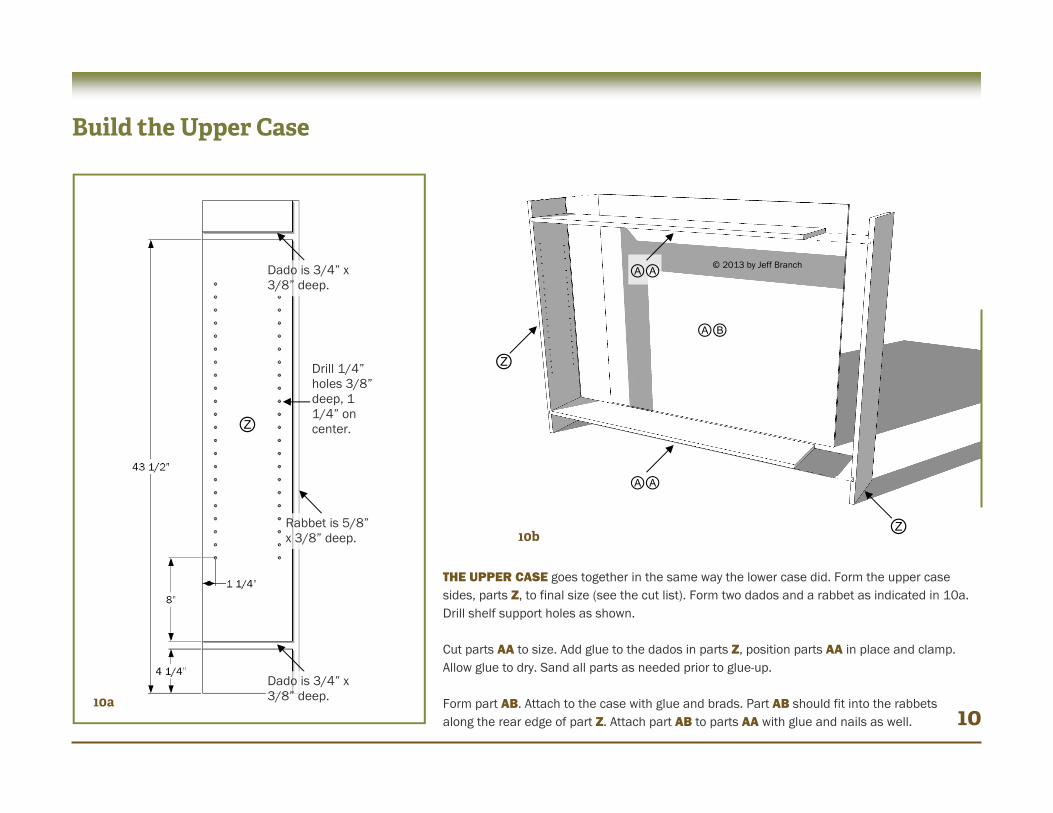
Dado is 3/4” x 3/8” deep.
Rabbet is 5/8” x 3/8” deep.
Dado is 3/4” x 3/8” deep.
Drill 1/4” holes 3/8” deep, 1 1/4” on center.
THE UPPER CASE goes together in the same way the lower case did. Form the upper case sides, parts Z, to final size (see the cut list). Form two dados and a rabbet as indicated in 10a. Drill shelf support holes as shown. Cut parts AA to size. Add glue to the dados in parts Z, position parts AA in place and clamp. Allow glue to dry. Sand all parts as needed prior to glue-up. Form part AB. Attach to the case with glue and brads. Part AB should fit into the rabbets along the rear edge of part Z. Attach part AB to parts AA with glue and nails as well. 10
ⒶⒶ
ⒶⒷ
ⒶⒶ
© 2013 by Jeff Branch

Build the Upper Case
11a
CONTINUE BUILDING THE upper case by adding the simulated panels to the sides and then creating and installing the face frame. The panels are created from 1/2” stock (I used MDF). Form parts AC, AD, AE and AF following the cut list. Attach these parts to the case sides with brads and glue. Add stop molding to the interior edges of the simulated panel as shown (parts AG and AH) using brads and glue. Repeat these steps to create a panel for the opposite side. Cut three shelves, parts AI to size and position them with 1/4” wood dowels or shelf pins. Form the face frame rails and stiles, parts AJ, AK and AL. Join them together with pocket screws and glue. I cut parts AL about 1/16” wider than what is called for in the cut list. Attach the face frame to the case using glue and clamps. Note that the top of the lower face frame rail is flush with the top edge of part AA. I later trimmed the excess 1/16” from part AL with a router and a flush trim bit.
11
ⒶⓀ
ⒶⒺ
ⒶⒶ
ⒶⒸ ⒶⒿ
ⒶⒻ
ⒶⒼ
ⒶⒹ
ⒶⒽ
ⒶⓁ
ⒶⓁ
ⒶⒾ
© 2013 by Jeff Branch
Add Moldings
12a
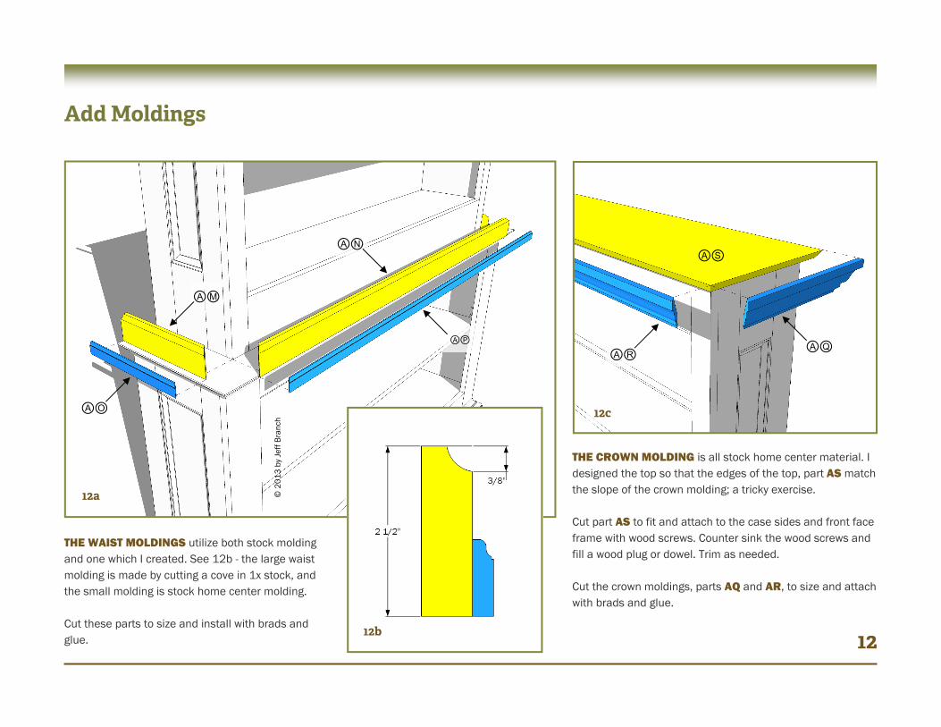
THE WAIST MOLDINGS utilize both stock molding and one which I created. See 12b - the large waist molding is made by cutting a cove in 1x stock, and the small molding is stock home center molding. Cut these parts to size and install with brads and glue. 12
ⒶⓂ
ⒶⓅ
ⒶⓃ
12b
12c
THE CROWN MOLDING is all stock home center material. I designed the top so that the edges of the top, part AS match the slope of the crown molding; a tricky exercise. Cut part AS to fit and attach to the case sides and front face frame with wood screws. Counter sink the wood screws and fill a wood plug or dowel. Trim as needed. Cut the crown moldings, parts AQ and AR, to size and attach with brads and glue.
ⒶⓄ
ⒶⓈ
ⒶⓇ ⒶⓆ
© 2
013
by
Jeff
Bra
nch
Final Construction
13a
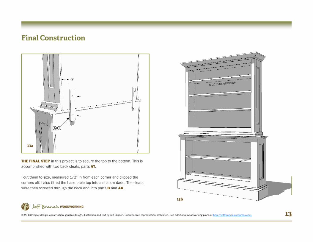
THE FINAL STEP in this project is to secure the top to the bottom. This is accomplished with two back cleats, parts AT. I cut them to size, measured 1/2” in from each corner and clipped the corners off. I also fitted the base table top into a shallow dado. The cleats were then screwed through the back and into parts B and AA.
13
ⒶⓉ
© 2013 Project design, construction, graphic design, illustration and text by Jeff Branch. Unauthorized reproduction prohibited. See additional woodworking plans at http://jeffbranch.wordpress.com.
Jeff Branch WOODWORKING 13b
© 2013 by Jeff Branch