780 4-20 ma input module - rs hydro · isco recommends that you read this manual completely ......
TRANSCRIPT
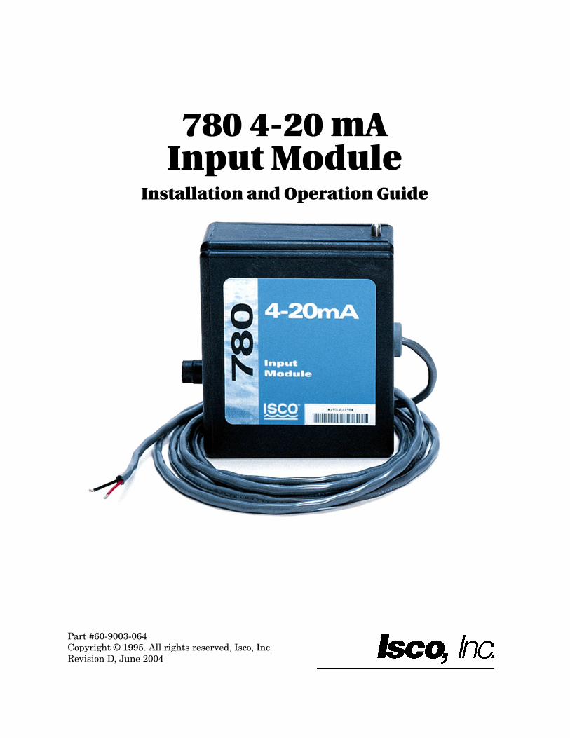
780 4-20 mAInput Module
Installation and Operation Guide
Part #60-9003-064Copyright © 1995. All rights reserved, Isco, Inc.Revision D, June 2004


Foreword
This instruction manual is designed to help you gain a thorough understanding of theoperation of the equipment. Isco recommends that you read this manual completelybefore placing the equipment in service.
Although Isco designs reliability into all equipment, there is always the possibility of amalfunction. This manual may help in diagnosing and repairing the malfunction.
If the problem persists, call or email the Isco Customer Service Department for assis-tance. Contact information is provided below. Simple difficulties can often be diag-nosed over the phone. If it is necessary to return the equipment to the factory forservice, please follow the shipping instructions provided by the Customer ServiceDepartment, including the use of the Return Authorization Number specified. Besure to include a note describing the malfunction. This will aid in the promptrepair and return of the equipment.
Isco welcomes suggestions that would improve the information presented in this man-ual or enhance the operation of the equipment itself.
Isco is continually improving its products and reserves the right to changeproduct specifications, replacement parts, schematics, and instructionswithout notice.
Contact Information
Phone: (800) 228-4373 (USA, Canada, Mexico)
(402) 464-0231 (Outside North America)
Repair Service: (800) 775-2965 (Analytical and Process Monitoring Instruments)
(800) 228-4373 (Samplers and Flow Meters)
Fax: (402) 465-3022
Email address: [email protected]
Website: www.isco.com
Return equipment to: 4700 Superior Street, Lincoln, NE 68504-1398
Other correspondence: P.O. Box 82531, Lincoln, NE 68501-2531
Revised February 12, 2003


1-1
780 4-20 mA Input Module
1.1 Introduction The 780 analog module is one of Isco’s interchangeable modulesfor the 6700 Series wastewater samplers. The module providesconnection between the sampler and non-Isco process controlequipment (for example: flow meters, chlorinators, or chartrecorders). The analog signal transmitted to the sampler canthen be used to pace, proportion, or trigger sampling routines.
The 780 module can only be used with 6700 Series samplers. Themodule receives a 4 to 20 mA analog signal from a non-Iscoinstrument and transmits it to the sampler. The 4 to 20 mAanalog signal is an industrial standard current loop for processcontrol equipment. In the sampler, the current range of 4 to 20mA represents percentage, with 4 mA equivalent to 0% and 20mA equivalent to 100%.
Figure 1-1 780 Module Installed on a Sampler
1.2 Installation To install the module:
1. Turn the sampler off.
2. Remove the connector cap in the module bay and move it aside.
3. Slide the module into the bay.
4. Push the module forward to be sure the connector is firmly seated.
780 4-20 mA Input Module
1-2
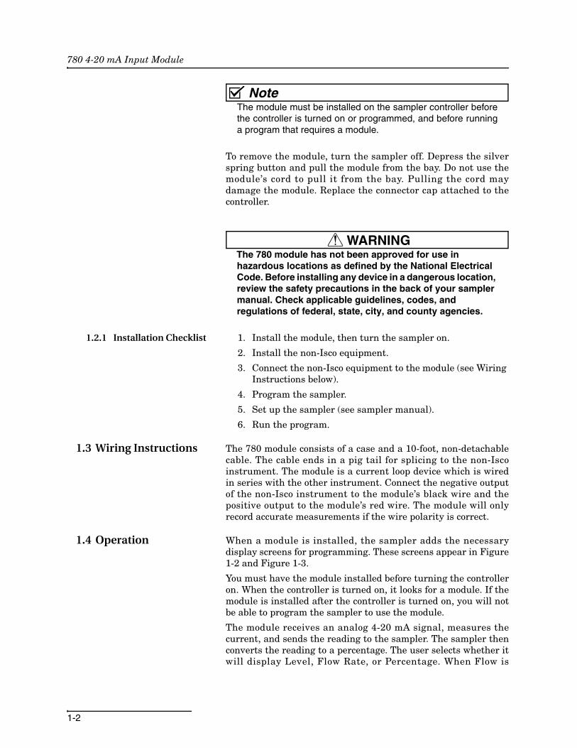
NoteThe module must be installed on the sampler controller beforethe controller is turned on or programmed, and before runninga program that requires a module.
To remove the module, turn the sampler off. Depress the silverspring button and pull the module from the bay. Do not use themodule’s cord to pull it from the bay. Pulling the cord maydamage the module. Replace the connector cap attached to thecontroller.
WARNINGThe 780 module has not been approved for use in hazardous locations as defined by the National Electrical Code. Before installing any device in a dangerous location, review the safety precautions in the back of your sampler manual. Check applicable guidelines, codes, and regulations of federal, state, city, and county agencies.
1.2.1 Installation Checklist 1. Install the module, then turn the sampler on.
2. Install the non-Isco equipment.
3. Connect the non-Isco equipment to the module (see Wiring Instructions below).
4. Program the sampler.
5. Set up the sampler (see sampler manual).
6. Run the program.
1.3 Wiring Instructions The 780 module consists of a case and a 10-foot, non-detachablecable. The cable ends in a pig tail for splicing to the non-Iscoinstrument. The module is a current loop device which is wiredin series with the other instrument. Connect the negative outputof the non-Isco instrument to the module’s black wire and thepositive output to the module’s red wire. The module will onlyrecord accurate measurements if the wire polarity is correct.
1.4 Operation When a module is installed, the sampler adds the necessarydisplay screens for programming. These screens appear in Figure1-2 and Figure 1-3.
You must have the module installed before turning the controlleron. When the controller is turned on, it looks for a module. If themodule is installed after the controller is turned on, you will notbe able to program the sampler to use the module.
The module receives an analog 4-20 mA signal, measures thecurrent, and sends the reading to the sampler. The sampler thenconverts the reading to a percentage. The user selects whether itwill display Level, Flow Rate, or Percentage. When Flow is

780 4-20 mA Input Module
1-3
selected, the current range of 4-20 mA represents flow rate, with4 mA equivalent to 0% flow and 20 mA equivalent to 100% of themaximum flow value entered.
For more information about programming, see the Programmingsection of the sampler manual.
NoteAn asterisk (*) appears next to the flow value if the module wasunable to take a reading. If an asterisk appears, the readingdisplayed is the last available reading.
1.4.1 Programmed Enable When a 4-20 mA module is installed, an additional enable optionis available. Depending on which display option you select, thisoption will be LEVEL, FLOW RATE, or PERCENT. For moreinformation about programming, see Sampler Enable in thesampler manual.
1.5 Maintenance The 780 module has no user-serviceable parts. Its case is com-pletely sealed to protect the internal components. To repair theunit, the case must be broken open and replaced. If you thinkyour module requires repair, contact the Isco Customer Servicedepartment for information on returning it to the factory.
1.6 Technical Specifications
Technical specifications for the 780 module are listed in the tablebelow:
Table 1-1 Technical Specifications for the 780 Analog Module
Weight 1.1 lbs (0.5 kg)
Dimensions 4.9 x 5.7 x 2.0 inches (12.4 x 14.5 x 5.1 cm)
Material Polystyrene
Operating Temperature 32° to 120° F (0° to 49° C)
Storage Temperature 0° to 140° F (-18° to 60° C)
Enclosure NEMA 4X, and 6, IP 67
Power Provided by the sampler.
Memory Nonvolatile programmable Flash.
Field updatable through the sampler.
Readings Programmable through sampler at 1, 2, 5, 10, 15, and 30 minute intervals.
Accuracy ± 0.5%
Resolution ± 0.1%
General Notes:
All weights may vary ± 0.2 lb (± 0.1 kg).
All lengths may very ± 1/4 inch (± 0.64 cm).

780 4-20 mA Input Module
1-4
1.6.1 Flash Memory and Software Upgrades
The 780 module has Flash memory to store its software. WithFlash technology, you can upgrade your module’s softwarewithout sending it back to the factory or replacing the chip.Simply connect a computer to the sampler with the moduleinstalled and run the Flash Update program.
NoteWhen updating the Flash memory, the module must beattached to the sampler and power must be supplied to thesampler.
1.6.2 How to Get Help Contact information can be found in the Foreword of thismanual.

780 4-20 mA Input Module
1-5
Figure 1-2 Programming the Sampler to use the 780 4-20 mA Module
S E L E C T U N I T S F O R
L E N G T H :
f t m
I N T E R V A L C H A N G E D - -
S E L E C T U N I T S F O R F L O W R A T E
c f s g p s g p m M g dl p s m 3 s m 3 h m 3 d
S E L E C T U N I T S F O R
F L O W V O L U M E :c f g a l M g a l
m 3 l i t
P R O G R A M M O D U L E ?Y E S N O
N E W M O D U L E S E T U P - - D O W N L O A D D A T A N O WO R L O S E A L L D A T A ! D O N E
I f a p p l i c a b l e . T h i s s c r e e n a p p e a r s o n l y w h e na s e l e c t i o n i s c h a n g e d . S e l e c t i n g N O w i l l c a u s e t h es a m p l e r t o n o t a c c e p t t h e m o d u l e s e t u p c h a n g e s .
M O D U L E I N S E R T E D - -
6 7 1 2 S A M P L E R S T A N D A R D P R O G R A M M I N G
F o r H E L P a t a n ys c r e e n p r e s s ? k e y
6 7 1 2 S A M P L E RE X T E N D E D P R O G R A M M I N G
Fo r H E L P a t a n ys c r e e n p r e s s ? k e y
RU NP R O G R A M
V I E W R E P O R TOT H E R F U N C T I O N S
RU N “ E X T E N D E D 1 ”P R O G R A M
V I E W R E P O R TOT H E R F U N C T I O N S
S I T E D E S C R I P T I O N“ FAC TO RY ”C H A N G E ?
Y E S N O
P R O G R A M N A M E“ E X T E N D E D 1 ”
C H A N G E ?Y E S N O
I f a p p l i c a b l e . T h i s s c r e e n a p p e a r s o n l y w h e n t h ei n t e r v a l i s c h a n g e d . I f N O i s s e l e c t e d , t h e s t o r a g ei n t e r v a l w i l l n o t c h a n g e .
S e e S a m p l e r M a n u a l
S e e S a m p l e r M a n u a l
T h i s s c r e e n a p p e a r s o n l y w h e n a m o d u l e h a s b e e nc h a n g e d o r i f t h e m o d u l e w a s u n p l u g g e d w h i l e t h e s a m p l e r w a s p o w e r e d u p .
N OT E :
To p r o g ra m t h e m o d u l e o rr u n a p r o g r a m t h a t r e q u i r e sa m o d u l e , y o u m u s t p l u g i nt h e m o d u l e b e f o r e t u r n i n go n t h e c o n t r o l l e r .
S t a n d a r d
E x t e n d e d
D O W N L O A D D A T A N O WO R L O S E A L L D A T A !
D O N E
D O W N L O A D D A T A N O WO R L O S E A L L D A T A ! D O N E
N o
C o n t i n u e w i t h t h e s a m p l e r p r o g r a m m i n g
s e q u e n c e ( s e e s a m p l e r m a n u a l )
YesSELECT A 4 - TO - 20 MA
SIGNAL TYPE:LEVEL FLOW RATEPERCENT OF MAX
D A T A S T O R A G EI N T E R V A L I N M I N U T E S
1 2 51 0 1 5 3 0

780 4-20 mA Input Module
1-6
Figure 1-3 Quick View: Programming the Sampler to Use the 780 4-20 mA Module
D A T A S T O R A G EI N T E R V A L I N M I N U T E S :
1 2 51 0 1 5 3 0
U N I T S S E L E C T E DL E N G T H : f t
U N I T S S E L E C T E D :F L O W R A T E : c f s
F L O W V O L U M E : M g a l
4 - T O - 2 0 m A M O D U L E
P E R C E N T O F M A X
M O D U L E I N S E R T E D - -
6 7 1 2 S A M P L E RS T A N D A R D P R O G R A M M I N G
F o r H E L P a t a n ys c r e e n p r e s s ? k e y
6 7 1 2 S A M P L E RE X T E N D E D P R O G R A M M I N G
F o r H E L P a t a n ys c r e e n p r e s s ? k e y
R U NP R O G R A M
V I E W R E P O R TO T H E R F U N C T I O N S
R U N “ E X T E N D E D 1 ”P R O G R A M
V I E W R E P O R TO T H E R F U N C T I O N S
S I T E D E S C R I P T I O N“ F A C T O R Y ”
P R O G R A M N A M E“ E X T E N D E D 1 ”
S I T E D E S C R I P T I O N“ F A C T O R Y ”
S E L E C T 4 - T O - 2 0 m A S I G N A L T Y P E :
L E V E L F L O W R A T EP E R C E N T O F M A X
S e e S a m p l e r M a n u a l
I f a p p i c a b l e . T h i s s c r e e n a p p e a r so n l y w h e n a s e l e c t i o n i s c h a n g e d .
S e l e c t i n g N O w i l l c a u s e t h e s a m p l e rt o n o t a c c e p t t h e m o d u l e s e t u p c h a n g e s .
I f a p p i c a b l e . T h i s s c r e e n a p p e a r so n l y w h e n a s e l e c t i o n i s c h a n g e d .I f N O i s s e l e c t e d , t h e s t o r a g ei n t e r v a l w i l l n o t c h a n g e .
S e e S a m p l e r M a n u a l
T h i s s c r e e n a p p e a r s o n l y w h e n a m o d u l e h a s b e e nc h a n g e d o r i f t h e m o d u l e w a s u n p l u g g e d w h i l e t h es a m p l e r w a s p o w e r e d .
I f N O i s s e l e c t e d , t h e s a m p l e r r e s p o n d s a s i f t h e r ei s n o m o d u l e .
N O T E :T o p r o g r a m t h e m o d u l e o rr u n a p r o g r a m t h a t r e q u i r e sa m o d u l e , y o u m u s t p l u g i nt h e m o d u l e b e f o r e t u r n i n go n t h e c o n t r o l l e r .
S t a n d a r d
E x t e n d e d
S E L E C T U N I T S F O RL E N G T H :
f t m
S E L E C T U N I T S F O RF L O W R A T E :
c f s g p s g p m M g dl p s m 3 s m 3 h m 3 d
S E L E C T U N I T S F O RF L O W V O L U M E :
c f g a l M g a lm 3 l i t
D O W N L O A D D A T A N O WO R L O S E A L L D A T A ! D O N E
D O W N L O A D D A T A N O WO R L O S E A L L D A T A ! D O N E
F L O W R A T E A T 2 0 m A :1 0 0 0 c f s
5 M I N U T E D A T A I N T E R V A L
N E W M O D U L E S E T U P - -D O W N L O A D D A T A N O W
O R L O S E A L L D A T A !D O N E
I N T E R V A L C H A N G E D - -
C o n t i n u e w i t h t h e s a m p l e r p r o g r a m m i n gs e q u e n c e ( s e e s a m p l e r m a n u a l ) .

Warranty
In the event of instrument problems, always contact the Isco Service Department, as problems can often bediagnosed and corrected without requiring an on-site visit. In the U.S.A., contact Isco Service at the numberslisted below. International customers should contact their local Isco agent or Isco International Customer Service.
Return Authorization
A return authorization number must be issued prior to shipping. Following authorization, Iscowill pay for surface transportation (excluding packing/crating) both ways for 30 days from thebeginning of the warranty period. After 30 days, expense for warranty shipments will be theresponsibility of the customer.
Shipping Address: Isco, Inc. - Attention Repair Service4700 Superior StreetLincoln NE 68504 USA
Mailing address: Isco, Inc.PO Box 82531Lincoln NE 68501 USA
Phone: Repair service: (800)775-2965 (lab instruments)
(800)228-4373 (samplers & flow meters)
Sales & General Information (800)228-4373 (USA & Canada)
Fax: (402) 465-3001
Email: [email protected]
Isco One Year Limited Factory Service Warranty *
Isco warrants covered products againstfailure due to faulty parts or workmanship fora period of one year (365 days) from theirshipping date, or from the date of installationby an authorized Isco Service Engineer, asmay be appropriate.
During the warranty period, repairs,replacements, and labor shall be provided atno charge. Isco’s liability is strictly limited torepair and/or replacement, at Isco’s solediscretion.
Failure of expendable items (e.g., charts,ribbon, tubing, glassware, seals and filters),or from normal wear, accident, misuse,corrosion, or lack of proper maintenance, isnot covered. Isco assumes no liability forany consequential damages.
Isco specifically disclaims any warranty ofmerchantability or fitness for a particularpurpose.
This warranty applies only to products soldunder the Isco trademark and is made in lieuof any other warranty, written or expressed.
No items may be returned for warrantyservice without a return authorization numberissued from Isco.
This warranty does not apply to the followingproducts: Process Analyzers, SFX 3560 SFEExtractor, 6100 VOC Sampler.
The warrantor is Isco, Inc. 4700 Superior,Lincoln, NE 68504, U.S.A.
August 2002 P/N 60-1002-040
* This warranty applies to USA customers. Customers in other countries should contact their Isco dealer for warranty service.
