7043a 1.0 pref
TRANSCRIPT
®
SUPERSERVER 7043L-8R
USER’S MANUAL
1.0
SUPER

The information in this User’s Manual has been carefully reviewed and is believed to beaccurate. The vendor assumes no responsibility for any inaccuracies that may becontained in this document, makes no commitment to update or to keep current theinformation in this manual, or to notify any person or organization of the updates. PleaseNote: For the most up-to-date version of this manual, please see ourweb site at www.supermicro.com.
SUPERMICRO COMPUTER reserves the right to make changes to the product described inthis manual at any time and without notice. This product, including software, if any, anddocumentation may not, in whole or in part, be copied, photocopied, reproduced, translatedor reduced to any medium or machine without prior written consent.
IN NO EVENT WILL SUPERMICRO COMPUTER BE LIABLE FOR DIRECT, INDIRECT,SPECIAL, INCIDENTAL, SPECULATIVE OR CONSEQUENTIAL DAMAGES ARISING FROMTHE USE OR INABILITY TO USE THIS PRODUCT OR DOCUMENTATION, EVEN IFADVISED OF THE POSSIBILITY OF SUCH DAMAGES. IN PARTICULAR, THE VENDORSHALL NOT HAVE LIABILITY FOR ANY HARDWARE, SOFTWARE, OR DATA STOREDOR USED WITH THE PRODUCT, INCLUDING THE COSTS OF REPAIRING, REPLACING,INTEGRATING, INSTALLING OR RECOVERING SUCH HARDWARE, SOFTWARE, ORDATA.
Any disputes arising between manufacturer and customer shall be governed by the laws ofSanta Clara County in the State of California, USA. The State of California, County ofSanta Clara shall be the exclusive venue for the resolution of any such disputes.Supermicro's total liability for all claims will not exceed the price paid for the hardwareproduct.
Unless you request and receive written permission from SUPER MICRO COMPUTER, youmay not copy any part of this document.
Information in this document is subject to change without notice. Other products andcompanies referred to herein are trademarks or registered trademarks of their respectivecompanies or mark holders.
Copyright © 2003 by SUPER MICRO COMPUTER INC.All rights reserved.Printed in the United States of America
i i i
Preface
Preface
About This Manual
This manual is written for professional system integrators and PC techni-cians. It provides information for the installation and use of the SuperServer7043L-8R. Installation and maintainance should be performed by experi-enced technicians only.
The SuperServer 7043L-8R is a high-end, dual processor 4U tower/rackmountable server based on the SC742S-600 4U rackmount server chas-sis and the X5DL8-GG, a dual processor motherboard that supports singleor dual Intel Xeon® processors up to 3.06 GHz at a Front Side (System) Busspeed of 533/400 MHz and up to 16 GB DDR-266/200 (PC2100/1600)SDRAM main memory.
Manual Organization
Chapter 1: Introduction
The first chapter provides a checklist of the main components included withthe server system and describes the main features of the SUPER X5DL8-GG mainboard and the SC742S-600 chassis, which comprise theSuperServer 7043L-8R.
Chapter 2: Server Installation
This chapter describes the steps necessary to install the SuperServer7043L-8R into a rack and check out the server configuration prior to pow-ering up the system. If your server was ordered without processor andmemory components, this chapter will refer you to the appropriate sectionsof the manual for their installation.
Chapter 3: System Interface
Refer here for details on the system interface, which includes the functionsand information provided by the control panel on the chassis as well asother LEDs located throughout the system.
SUPERSERVER 7043L-8R Manual
iv
Chapter 4: System Safety
You should thoroughly familiarize yourself with this chapter for a generaloverview of safety precautions that should be followed when installing andservicing the SuperServer 7043L-8R.
Chapter 5: Advanced Motherboard Setup
Chapter 5 provides detailed information on the X5DL8-GG motherboard, in-cluding the locations and functions of connections, headers and jumpers.Refer to this chapter when adding or removing processors or main memoryand when reconfiguring the motherboard.
Chapter 6: Advanced Chassis Setup
Refer to Chapter 6 for detailed information on the SC742S-600 server chas-sis. You should follow the procedures given in this chapter when installing,removing or reconfiguring SCSI or peripheral drives and when replacingsystem power supply units and cooling fans.
Chapter 7: BIOS
The BIOS chapter includes an introduction to BIOS and provides detailedinformation on running the CMOS Setup Utility.
Appendix A: BIOS POST Messages
Appendix B: BIOS POST Codes
Appendix C: System Specifications

v
Preface
Notes
vi
Table of Contents
PrefaceAbout This Manual ...................................................................................................... iiiManual Organization ................................................................................................... iii
Chapter 1: Introduction1-1 Overview ......................................................................................................... 1-11-2 Motherboard Features ................................................................................... 1-21-3 Server Chassis Features .............................................................................. 1-41-4 Contacting Supermicro .................................................................................. 1-6
Chapter 2: Server Installation2-1 Overview ......................................................................................................... 2-12-2 Unpacking the 7043L-8R ............................................................................... 2-12-3 Preparing for Setup ....................................................................................... 2-12-4 Installing the 7043L-8R into a Rack ............................................................ 2-32-5 Checking the Motherboard Setup ................................................................ 2-72-6 Checking the Drive Bay Setup ..................................................................... 2-9
Chapter 3: System Interface3-1 Overview ......................................................................................................... 3-13-2 Control Panel Buttons .................................................................................... 3-1
Power ........................................................................................................ 3-1Reset .......................................................................................................... 3-1
3-3 Control Panel LEDs ........................................................................................ 3-2Power ........................................................................................................ 3-2HDD ............................................................................................................ 3-2NIC1 ............................................................................................................ 3-2NIC2 ............................................................................................................ 3-2Overheat ................................................................................................... 3-2Power Fail ................................................................................................. 3-3
3-4 SCSI Drive Carrier LEDs ............................................................................... 3-33-5 LAN (Ethernet) Port LEDs ............................................................................. 3-4
SUPERSERVER 7043L-8R Manual
Chapter 4: System Safety4-1 Electrical Safety Precautions ........................................................................ 4-14-2 General Safety Precautions .......................................................................... 4-24-3 ESD Safety Precautions ................................................................................. 4-34-4 Operating Precautions .................................................................................... 4-4
Chapter 5: Advanced Motherboard Setup5-1 Handling the X5DL8-GG Motherboard ......................................................... 5-15-2 PGA Processor and Heatsink Installation ................................................... 5-25-3 Connecting Cables .......................................................................................... 5-5
Connecting Data Cables .......................................................................... 5-5Connecting Power Cables ....................................................................... 5-5Connecting the Control Panel ................................................................. 5-6
5-4 I/O Ports ............................................................................................................ 5-75-5 Installing Memory ............................................................................................. 5-75-6 Adding PCI Cards ............................................................................................ 5-95-7 Motherboard Details ...................................................................................... 5-10
Super X5DL8-GG Layout ....................................................................... 5-10X5DL8-GG Quick Reference ................................................................. 5-11
5-8 Connector Definitions ................................................................................... 5-12ATX Power Connector .......................................................................... 5-12Processor Power Connector ................................................................ 5-12NMI Button ................................................................................................ 5-12Power LED ............................................................................................... 5-12HDD LED .................................................................................................. 5-13NIC1 LED .................................................................................................. 5-13NIC2 LED .................................................................................................. 5-13Overheat LED (OH) ............................................................................... 5-13Power Fail LED ...................................................................................... 5-13Reset Button ........................................................................................... 5-14Power Button .......................................................................................... 5-14Serial Ports .............................................................................................. 5-14Chassis Intrusion .................................................................................... 5-14Universal Serial Bus (USB0/1) ............................................................ 5-15Extra Universal Serial Bus Headers ................................................... 5-15PS/2 Keyboard and Mouse Ports ......................................................... 5-15HD LED Indicator ..................................................................................... 5-16Power LED ............................................................................................... 5-16Speaker .................................................................................................... 5-16
vii
Table of Contents
viii
Third Power Supply Fail Header .......................................................... 5-16GLAN1/GLAN2 Ethernet Ports ............................................................. 5-17Wake-On-LAN ......................................................................................... 5-17IPMB .......................................................................................................... 5-17SMB ........................................................................................................... 5-17
5-9 Onboard Indicators ....................................................................................... 5-18GLAN1/GLAN2 LEDs .............................................................................. 5-18Debug LEDs ............................................................................................. 5-18CR5 LED ................................................................................................... 5-19
5-10 DIP Switch Settings ...................................................................................... 5-19DIP Switch 4: Processor Speed .......................................................... 5-19
5-11 Jumper Settings ............................................................................................. 5-20Explanation of Jumpers ......................................................................... 5-20CMOS Clear .............................................................................................. 5-20Main Power Override ............................................................................. 5-20Fan Detection Select .............................................................................. 5-21Chassis/Overheat Fan Select ............................................................... 5-21Watch Dog Enable/Disable .................................................................... 5-21Speaker Enable/Disable ......................................................................... 5-21GLAN1 Enable/Disable .......................................................................... 5-22GLAN2 Enable/Disable .......................................................................... 5-22SCSI Enable/Disable ................................................................................ 5-22SCSI Termination Enable/Disable .......................................................... 5-22PCI-X Bus Speed Setting ....................................................................... 5-2333 MHz PCI Enable/Disable ................................................................... 5-23PCI 3.3V Standby Enable/Disable ........................................................ 5-23Spread Spectrum .................................................................................... 5-24Front Side Bus Speed ........................................................................... 5-24VGA Enable/Disable .............................................................................. 5-24
5-12 Parallel Port, Floppy/Hard Drive and SCSI Connections ......................... 5-25Parallel Port Connector ......................................................................... 5-25Floppy Connector ................................................................................... 5-26IDE Connectors ...................................................................................... 5-26Ultra320 SCSI Connectors ..................................................................... 5-27
5-13 Installing Software Drivers .......................................................................... 5-28
SUPERSERVER 7043L-8R Manual
Table of Contents
ix
Chapter 6: Advanced Chassis Setup6-1 Static-Sensitive Devices ................................................................................ 6-16-2 Front Control Panel ......................................................................................... 6-36-3 System Fans .................................................................................................... 6-4
Fan Failure ................................................................................................. 6-4Replacing System Fans ........................................................................... 6-4
6-4 Drive Bay Installation ...................................................................................... 6-5SCSI Drives ............................................................................................... 6-5Installing Components in the 5 1/4" Drive Bays ................................. 6-8
6-5 Power Supply .................................................................................................. 6-9Power Supply Failure .............................................................................. 6-9Replacing the Power Supply .................................................................. 6-9
Chapter 7: BIOS7-1 Introduction ....................................................................................................... 7-17-2 BIOS Features .................................................................................................. 7-27-3 Running Setup .................................................................................................. 7-27-4 Main BIOS Setup .............................................................................................. 7-37-5 Advanced Setup .............................................................................................. 7-47-6 Chipset Setup ................................................................................................. 7-157-7 PCI PnP Setup ................................................................................................ 7-167-8 Power Setup .................................................................................................. 7-187-9 Boot Setup ...................................................................................................... 7-207-10 Security Setup ............................................................................................... 7-227-10 Exit Setup ....................................................................................................... 7-24
Appendices:Appendix A: BIOS POST Messages ..................................................................... A-1Appendix B: BIOS POST Codes ............................................................................. B-1Appendix C: System Specifications ...................................................................... C-1

Notes
x
SUPERSERVER 7043L-8R Manual

Chapter 1
Introduction
1-1 Overview
The Supermicro SuperServer 7043L-8R is a high-end dual processor serverthat can be utilized either in a tower or in a rackmount configuration. The7043L-8R is comprised of two main subsystems: the SC742S-600 high-endserver chassis and the X5DL8-GG dual Xeon processor motherboard.Please refer to our web site for information on operating systems that havebeen certified for use with the SuperServer 7043L-8R.
In addition to the mainboard and chassis, various hardware componentshave been included with the SuperServer 7043L-8R, as listed below:
! Up to two (2) 604/603-pin Intel Xeon processors (optional)
! Two (2) CPU heatsinks* (FAN-042-CF)
! Two (2) heatsink retention clip assemblies* (SKT-095-604E)
! Up to 16 GB ECC registered DDR-266/200 SDRAM memory (optional)
! One (1) 3.5" floppy drive
! Three (3) 5.25" drive bays
! One (1) ribbon cable for IDE CD-ROM
! One (1) ATA100 ribbon cable for IDE hard drives
! One (1) USB cable for two-port front side access
! One (1) dual channel SCA SCSI backplane
! Seven (7) SCA 1-inch high SCSI drive carriers
! SCSI AccessoriesOne (1) internal 68-pin Ultra320 SCSI cable for SCA SCSI backplaneOne (1) set of SCSI driver diskettesOne (1) SCSI manual
Chapter 1: Introduction
1-1

1-2
SUPERSERVER 7043L-8R Manual
1-2 Motherboard Features
At the heart of the SuperServer 7043L-8R lies the X5DL8-GG, a dual pro-cessor motherboard designed to provide maximum performance. Below arethe main features of the X5DL8-GG.
Chipset
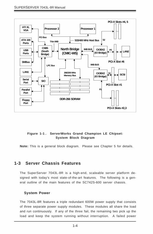
The X5DL8-GG is based on the ServerWorks Grand Champion LETM chipset,which is a high-performance core logic chipset designed for dual-proces-sor systems. See Figure 1-1 for a block diagram of the GC-LE.
The ServerWorks Grand Champion LETM is a high-performance SystemSetcore logic chipset that consists of a North Bridge, a South Bridge and an IObridge.
The North Bridge interfaces directly to the processor bus and integrates thefunctions of the main memory subsystem and the IMB bus interface unit.The memory subsystem consists of an 8-DIMM configuration accessed overa 144-bit memory bus (most chipsets have a 72-bit memory bus), whichprovides a significant boost in performance.
The South Bridge provides various integrated functions, including the PCI toISA bridge and support for UDMA100, security (passwords and systemprotection), Plug & Play, USBs, power management, interrupt controllersand the SMBus.
The CIOBX2 is an integrated IO bridge that provides high-performance dataflow between the IMB interface and the dual peer PCI-X bus interfaces.The X5DL8-GG has two CIOBX2 bridges (four buses).
! Rackmount hardware with screws, optional (CSE-PT26):Two (2) rack rail assembliesSix (6) brackets for mounting the rack rails
! One (1) CD containing drivers and utilities
! SuperServer 7043L-8R User's Manual
* Product may change without notice.

1-3
Chapter 1: Introduction
Processors
The X5DL8-GG supports single or dual 604/603-pin Intel Xeon processorsof up to 3.06 GHz at a 533/400 MHz FSB (front side bus). Please refer tothe motherboard description pages on our web site for a complete listing ofsupported processors (http://www.supermicro.com/Product_page/product-m.htm).
Memory
The X5DL8-GG has eight 184-pin DIMM slots that can support up to 16 GBof registered ECC DDR-266/200 (PC2100/1600) SDRAM. Module sizes of128MB, 256MB, 512MB 1GB and 2GB may be used to populate the DIMMslots. (The X5DL8-GG was designed to support 2GB DIMM modules in eachslot, however 2GB memory modules have not yet been validated.)
Onboard SCSI
Onboard SCSI is provided with an Adaptec AIC-7902 SCSI chip, which sup-ports dual-channel, Ultra320 SCSI at a throughput of 320 MB/sec.
PCI Expansion Slots
The X5DL8-GG has a total of six PCI expansion slots, three of which maybe configured for 133 MHz operation. See Chapter 5 for details.
Onboard Controllers/Ports
One floppy drive controller and two onboard ATA/100 controllers are pro-vided to support up to four hard drives or ATAPI devices. The color-codedI/O ports include two COM ports, a parallel port, two USB ports, PS/2 mouseand keyboard ports and two G-bit Ethernet ports. Two front side USB portsare also included on the front of the chassis.
Other Features
Other onboard features that promote system health include onboard voltagemonitors, a chassis intrusion header, auto-switching voltage regulators,chassis and CPU overheat sensors, virus protection and BIOS rescue.
1-4
SUPERSERVER 7043L-8R Manual
1-3 Server Chassis Features
The SuperServer 7043L-8R is a high-end, scaleable server platform de-signed with today's most state-of-the-art features. The following is a gen-eral outline of the main features of the SC742S-600 server chassis.
System Power
The 7043L-8R features a triple redundant 600W power supply that consistsof three separate power supply modules. These modules all share the loadand run continuously. If any of the three fail, the remaining two pick up theload and keep the system running without interruption. A failed power
Figure 1-1 . ServerWorks Grand Champion LE Chipset:System Block Diagram
Note: This is a general block diagram. Please see Chapter 5 for details.
North Bridge(CMIC-WS)
533/400 MHz Host Bus
266/200 MHzMemory Bus
ATA 100Ports
CIOBX2(IO Bridge)
Processor 2 Processor 1
DDR-266 SDRAM
PCI-X Slot #6
CSB5(SouthBridge)
USBPorts
SMBus
CIOBX2(IO Bridge)
LAN2P2IMB BUS
S2
PCI-X Slots #4, 5
IMB BUS
SCSI
PCI-X Slot #1
S1
P1
PCI-X Slots #2,3
Thin IMB
SIO
ATI XLVGA
PCI Bus
LPC Bus
SerialPort
ParallelPort
FloppyPort
LAN1
1-5
Chapter 1: Introduction
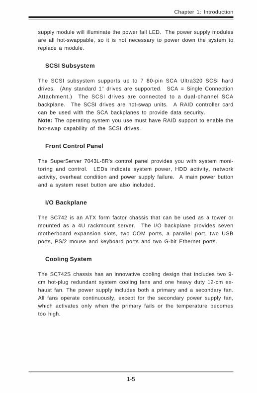
supply module will illuminate the power fail LED. The power supply modulesare all hot-swappable, so it is not necessary to power down the system toreplace a module.
SCSI Subsystem
The SCSI subsystem supports up to 7 80-pin SCA Ultra320 SCSI harddrives. (Any standard 1" drives are supported. SCA = Single ConnectionAttachment.) The SCSI drives are connected to a dual-channel SCAbackplane. The SCSI drives are hot-swap units. A RAID controller cardcan be used with the SCA backplanes to provide data security.Note: The operating system you use must have RAID support to enable thehot-swap capability of the SCSI drives.
Front Control Panel
The SuperServer 7043L-8R's control panel provides you with system moni-toring and control. LEDs indicate system power, HDD activity, networkactivity, overheat condition and power supply failure. A main power buttonand a system reset button are also included.
I/O Backplane
The SC742 is an ATX form factor chassis that can be used as a tower ormounted as a 4U rackmount server. The I/O backplane provides sevenmotherboard expansion slots, two COM ports, a parallel port, two USBports, PS/2 mouse and keyboard ports and two G-bit Ethernet ports.
Cooling System
The SC742S chassis has an innovative cooling design that includes two 9-cm hot-plug redundant system cooling fans and one heavy duty 12-cm ex-haust fan. The power supply includes both a primary and a secondary fan.All fans operate continuously, except for the secondary power supply fan,which activates only when the primary fails or the temperature becomestoo high.
1-6
SUPERSERVER 7043L-8R Manual
1-4 Contacting Supermicro
HeadquartersAddress: SuperMicro Computer, Inc.
980 Rock Ave.San Jose, CA 95131 U.S.A.
Tel: +1 (408) 503-8000Fax: +1 (408) 503-8008Email: [email protected] (General Information)
[email protected] (Technical Support)Web Site: www.supermicro.com
EuropeAddress: SuperMicro Computer B.V.
Het Sterrenbeeld 28, 5215 ML's-Hertogenbosch, The Netherlands
Tel: +31 (0) 73-6400390Fax: +31 (0) 73-6416525Email: [email protected] (General Information)
[email protected] (Technical Support)[email protected] (Customer Support)
Asia-PacificAddress: SuperMicro, Taiwan
D5, 4F, No. 16 Chien-Ba RoadChung-Ho 235, Taipei Hsien, Taiwan, R.O.C.
Tel: +886-(2) 8226-3990Fax: +886-(2) 8226-3991Web Site: www.supermicro.com.twTechnical Support:Email: [email protected]: 886-2-8228-1366, ext.132 or 139
Chapter 2: Server Installation
2-1
Chapter 2
Server Installation
2-1 Overview
This chapter provides a quick setup checklist to get your SuperServer7043L-8R up and running. Following these steps in the order given shouldenable you to have the system operational within a minimum amount of time.This quick setup assumes that your SuperServer 7043L-8R system hascome to you with the processors and memory preinstalled. If your systemis not already fully integrated with a motherboard, processors, systemmemory etc., please turn to the chapter or section noted in each step fordetails on installing specific components. The 7043L-8R may be employedeither as a tower or mounted in a rack as a 4U rackmount chassis. If usingit as a server, please read Server Precautions in the next section and thenskip ahead to Section 2-5.
2-2 Unpacking the 7043L-8R
You should inspect the box the SuperServer 7043L-8R was shipped in andnote if it was damaged in any way. If the server itself shows damage youshould file a damage claim with the carrier who delivered it.
Decide on a suitable location for the SuperServer 7043L-8R. It should besituated in a clean, dust-free area that is well ventilated. Avoid areaswhere heat, electrical noise and electromagnetic fields are generated. Youwill also need it placed near a grounded power outlet. Read the Rack andServer Precautions in the next section.
2-3 Preparing for Setup
The box the SuperServer 7043L-8R was shipped in may include two sets ofrail assemblies, two rail mounting brackets and mounting screws neededfor installing the system into a rack (optional kit). Follow the steps in theorder given to complete the installation process in a minimum amount of time.Please read this section in its entirety before you begin the installationprocedure outlined in the sections that follow.
2-2
SUPERSERVER 7043L-8R Manual
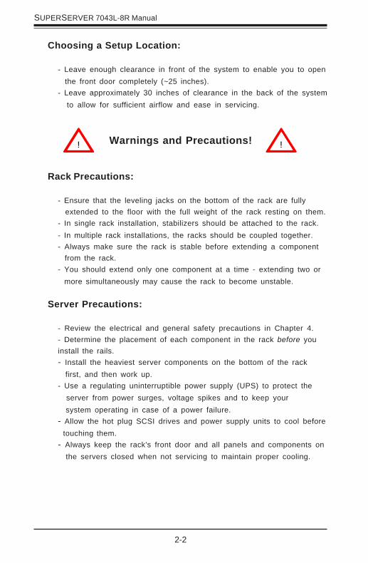
Choosing a Setup Location:
- Leave enough clearance in front of the system to enable you to open the front door completely (~25 inches).
- Leave approximately 30 inches of clearance in the back of the system to allow for sufficient airflow and ease in servicing.
Rack Precautions:
- Ensure that the leveling jacks on the bottom of the rack are fully extended to the floor with the full weight of the rack resting on them.- In single rack installation, stabilizers should be attached to the rack.- In multiple rack installations, the racks should be coupled together.- Always make sure the rack is stable before extending a component from the rack.- You should extend only one component at a time - extending two or
more simultaneously may cause the rack to become unstable.
Server Precautions:
- Review the electrical and general safety precautions in Chapter 4.- Determine the placement of each component in the rack before youinstall the rails.- Install the heaviest server components on the bottom of the rack
first, and then work up.- Use a regulating uninterruptible power supply (UPS) to protect the
server from power surges, voltage spikes and to keep your system operating in case of a power failure.
- Allow the hot plug SCSI drives and power supply units to cool before touching them.
- Always keep the rack's front door and all panels and components on the servers closed when not servicing to maintain proper cooling.
! !Warnings and Precautions!

Chapter 2: Server Installation
2-3
2-4 Installing the 7043L-8R into a Rack
This section provides information on installing the SuperServer 7043L-8Rinto a rack unit. If the 7043L-8R has already been mounted into a rack or ifyou are using it as a tower, you can skip ahead to Sections 2-5 and 2-6.There are a variety of rack units on the market, which may mean the as-sembly procedure will differ slightly. The following is a guideline for install-ing the 7043L-8R into a rack with the rack rails provided in the rackmountkit. You should also refer to the installation instructions that came with therack unit you are using.
Identifying the Sections of the Rack Rails:
The 7043L-8R rackmount kit (CSE-PT26 or CSE-PT26B - black) includes tworack rail assemblies. Each of these assemblies consist of three sections:an inner fixed chassis rail that secures to the 7043L-8R (A), an outer fixedrack rail that secures directly to the rack itself (B) and a sliding rail guidesandwiched between the two, which should remain attached to the fixedrack rail (see Figure 2-1.) The A and B rails must be detached from eachother to install. Two chassis handles are also included with the rail kit.
To remove the fixed chassis rail (A), pull it out as far as possible - youshould hear a "click" sound as a locking tab emerges from inside the railassembly and locks the inner rail. Depress the locking tab to pull theinner rail completely out. Do this for both assemblies.
Figure 2-1. Identifying the Sections of the Rack Rails
B
A
2-4
SUPERSERVER 7043L-8R Manual
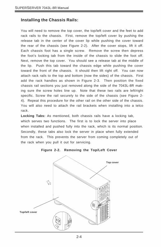
Installing the Chassis Rails:
You will need to remove the top cover, the top/left cover and the feet to addrack rails to the chassis. First, remove the top/left cover by pushing therelease tab in the center of the cover lip while pushing the cover towardthe rear of the chassis (see Figure 2-2). After the cover stops, lift it off.Each chassis foot has a single screw. Remove the screw then depressthe foot’s locking tab from the inside of the chassis to slide the foot off.Next, remove the top cover. You should see a release tab at the middle ofthe lip. Push this tab toward the chassis edge while pushing the covertoward the front of the chassis. It should then lift right off. You can nowattach rack rails to the top and bottom (now the sides) of the chassis. Firstadd the rack handles as shown in Figure 2-3. Then position the fixedchassis rail sections you just removed along the side of the 7043L-8R mak-ing sure the screw holes line up. Note that these two rails are left/rightspecific. Screw the rail securely to the side of the chassis (see Figure 2-4). Repeat this procedure for the other rail on the other side of the chassis.You will also need to attach the rail brackets when installing into a telcorack.Locking Tabs: As mentioned, both chassis rails have a locking tab,which serves two functions. The first is to lock the server into placewhen installed and pushed fully into the rack, which is its normal position.Secondly, these tabs also lock the server in place when fully extendedfrom the rack. This prevents the server from coming completely out ofthe rack when you pull it out for servicing.
Figure 2-2. Removing the Top/Left Cover
Top/left cover
Top cover
Chapter 2: Server Installation
2-5
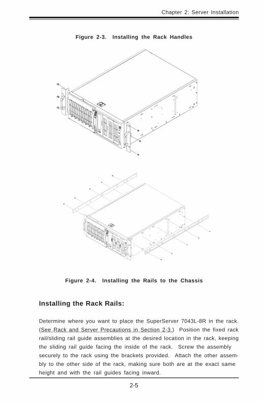
Installing the Rack Rails:
Determine where you want to place the SuperServer 7043L-8R in the rack.(See Rack and Server Precautions in Section 2-3.) Position the fixed rackrail/sliding rail guide assemblies at the desired location in the rack, keepingthe sliding rail guide facing the inside of the rack. Screw the assemblysecurely to the rack using the brackets provided. Attach the other assem-bly to the other side of the rack, making sure both are at the exact sameheight and with the rail guides facing inward.
Figure 2-4. Installing the Rails to the Chassis
Figure 2-3. Installing the Rack Handles

2-6
SUPERSERVER 7043L-8R Manual
Figure 2-5. Installing the Server into a Rack
Installing the Server into the Rack:
You should now have rails attached to both the chassis and the rack unit.The next step is to install the server into the rack. Do this by lining up therear of the chassis rails with the front of the rack rails. Slide the chassisrails into the rack rails, keeping the pressure even on both sides (you mayhave to depress the locking tabs when inserting).
When the server has been pushed completely into the rack, you shouldhear the locking tabs "click". Finish by inserting and tightening the thumb-screws that hold the front of the server to the rack (see Figure 2-5).
Chapter 2: Server Installation
2-7
2-5 Checking the Motherboard Setup
After setting up the the 7043L-8R, you will need to open the unit to makesure the motherboard is properly installed and all the connections havebeen made.
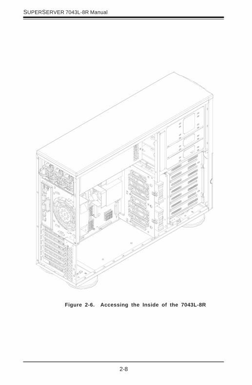
1. Accessing the inside of the 7043L-8R (see Figure 2-6):
(If rack mounted, first release the retention screws that secure the unitto the rack. Grasp the two handles on either side and pull the unitstraight out until it locks (you will hear a "click").) Depress the twobuttons on the top (side if tower) of the chassis to release the cover.There is a large rectangular recess in the middle front of the cover tohelp you push the cover away from you until it stops. You can then liftthe cover from the chassis to gain full access to the inside of the server.
2. Check the CPUs (processors):
You should have one or two processors already installed into thesystem board. Each processor should have its own heatsink attached.See Chapter 5 for instructions on processor installation.
3. CPU clock ratio setting:
The CPU speed should be automatically detected.
4. Check the system memory:
Your 7043L-8R server system may have come with system memory al-ready installed. Make sure all DIMMs are fully seated in their slots. Fordetails on adding system memory, refer to Chapter 5.
5. Installing add-on cards:
If desired, you can install add-on cards to the system. See Chapter 5 fordetails on installing PCI add-on cards.
6. Check all cable connections and airflow:
Make sure all power and data cables are properly connected and notblocking the chassis airflow. See Chapter 5 for details on cable connec-tions.
2-8
SUPERSERVER 7043L-8R Manual
Figure 2-6. Accessing the Inside of the 7043L-8R
Chapter 2: Server Installation
2-9
2-6 Checking the Drive Bay Setup
Next, you should check to make sure the peripheral drives and the SCSIdrives and SCA backplane have been properly installed and all connectionshave been made.
1. Accessing the drive bays:
All drives can be accessed from the front of the server. For servicingthe CD-ROM and floppy drives, you will need to remove the top/left chas-sis cover. The SCSI disk drives can be installed and removed from thefront of the chassis without removing any chassis covers.
2. Installing components into the 5.25" drive bay:
To install components into the 5.25" drive bays, you must first remove thetop/left chassis cover as described in the previous section. Refer toChapter 6 for details.
3. Installing CD-ROM and floppy disk drives:
Refer to Chapter 6 if you need to reinstall a CD-ROM and/or floppy diskdrive to the system.
4. Check the SCSI disk drives:
Depending upon your system's configuration, your system may have oneor more drives already installed. If you need to install SCSI drives, pleaserefer to Chapter 6.
5. Check the airflow:
Airflow is provided by two 9-cm cooling fans and a heavy duty 12-cmexhaust fan. The system component layout was carefully designed topromote sufficient airflow through the 4U rackmount space. Also notethat all power and data cables have been routed in such a way that theydo not block the airflow generated by the fans. Keep this in mind whenyou reroute them after working on the system.

2-10
SUPERSERVER 7043L-8R Manual
6. Supplying power to the system:
The last thing you must do is to provide input power to the system. Plugthe power cords from the power supply units into a high-quality powerstrip that offers protection from electrical noise and power surges. It isrecommended that you use an uninterruptible power supply (UPS). Fi-nally, depress the power on button on the front of the chassis.

Chapter 3: System Interface
3-1
Chapter 3
System Interface
3-1 Overview
There are several LEDs on the control panel as well as two for each SCSIdrive carrier and LAN (Ethernet) port. These LEDs are to keep you con-stantly informed of the overall status of the system and the activity andhealth of specific components. There are also two buttons on the chassiscontrol panel.
3-2 Control Panel Buttons
There are three push-button buttons located on the front of the chassis.These are (in order from left to right) a power on/off button, an NMI (Non-Maskable Interrupt) button and a reset button.
! POWER: This is the main power button, which is used to apply or turnoff the main system power. Turning off system power with this buttonremoves the main power but keeps standby power supplied to the system.
! NMI: NMI stands for "non-maskable interrupt". Pressing this buttonissues a non-maskable interrupt to force the server into a halt state. This isused for diagnostic purposes, and allows you to perform a memory down-load to determine the cause of a problem.
3-2
SUPERSERVER 7043L-8R Manual
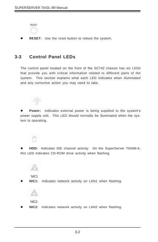
! RESET: Use the reset button to reboot the system.
3-3 Control Panel LEDs
The control panel located on the front of the SC742 chassis has six LEDsthat provide you with critical information related to different parts of thesystem. This section explains what each LED indicates when illuminatedand any corrective action you may need to take.
! Power: Indicates external power is being supplied to the system'spower supply unit. This LED should normally be illuminated when the sys-tem is operating.
! HDD: Indicates IDE channel activity. On the SuperServer 7043M-6,this LED indicates CD-ROM drive activity when flashing.
! NIC1: Indicates network activity on LAN1 when flashing.
! NIC2: Indicates network activity on LAN2 when flashing.NIC2
NIC1
Chapter 3: System Interface
3-3
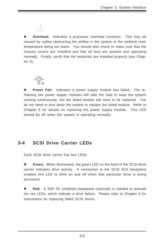
! Overheat: Indicates a processor overheat condition. This may becaused by cables obstructing the airflow in the system or the ambient roomtemperature being too warm. You should also check to make sure that thechassis covers are installed and that all fans are present and operatingnormally. Finally, verify that the heatsinks are installed properly (see Chap-ter 5).
! Power Fail: Indicates a power supply module has failed. The re-maining two power supply modules will take the load to keep the systemrunning continuously, but the failed module will need to be replaced. Youdo not need to shut down the system to replace the failed module. Refer toChapter 6 for details on replacing the power supply module. This LEDshould be off when the system is operating normally.
3-4 SCSI Drive Carrier LEDs
Each SCSI drive carrier has two LEDs.
! Green: When illuminated, the green LED on the front of the SCSI drivecarrier indicates drive activity. A connection to the SCSI SCA backplaneenables this LED to blink on and off when that particular drive is beingaccessed.
! Red: A SAF-TE compliant backplane (optional) is needed to activatethe red LEDs, which indicate a drive failure. Please refer to Chapter 6 forinstructions on replacing failed SCSI drives.

3-4
SUPERSERVER 7043L-8R Manual
LEDColorOff
GreenOrange
DefinitionNo Connection
100 MHz1 GHz
LAN LED Indicator (Right)LEDColorOff
Yellow
DefinitionNot Active
Active
LAN LED Indicator (Left)
3-5 LAN (Ethernet) Port LEDs
The Gb LAN (Ethernet) ports have two LEDs, which are used to give con-nectivi ty status as shown below. The yel low (left) LED f lashes toindicate activity while the other (right) LED may flash green or orange toindicate the speed of the connection. See the tables below for the func-tions associated with these LEDs.

Chapter 4: System Safety
4-1
Chapter 4
System Safety
4-1 Electrical Safety Precautions
!
Basic electrical safety precautions should be followed to protectyourself from harm and the SuperServer 7043L-8R from damage:
! Be aware of the locations of the power on/off switch on the chassisas well as the room's emergency power-off switch, disconnectionswitch or electrical outlet. If an electrical accident occurs, you canthen quickly remove power from the system.
! Do not work alone when working with high voltage components.
! Power should always be disconnected from the system when removingor installing main system components, such as the motherboard,memory modules and the CD-ROM and f loppy dr ives. Whendisconnecting power, you should first power down the system withthe operating system and then unplug the power cords of all thepower supply units in the system.
! When working around exposed electrical circuits, another person whois familiar with the power-off controls should be nearby to switch offthe power if necessary.
! Use only one hand when working with powered-on electr icalequipment. This is to avoid making a complete circuit, which willcause electrical shock. Use extreme caution when using metal tools,which can easily damage any electrical components or circuit boardsthey come into contact with.
! Do not use mats designed to decrease electrostatic discharge asprotection from electrical shock. Instead, use rubber mats that havebeen specifically designed as electrical insulators.
4-2
SUPERSERVER 7043L-8R Manual
4-2 General Safety Precautions
Follow these rules to ensure general safety:
! Keep the area around the SuperServer 7043L-8R clean and free ofclutter.
! The SuperServer 7043L-8R weighs approximately 78 lbs. (35.5 kg.)when fully loaded. When lifting the system, two people at either endshould lift slowly with their feet spread out to distribute the weight.Always keep your back straight and lift with your legs.
! Place the chassis top/side cover and any system components that havebeen removed away from the system or on a table so that they won'taccidentally be stepped on.
! While working on the system, do not wear loose clothing such asneckties and unbuttoned shirt sleeves, which can come into contactwith electrical circuits or be pulled into a cooling fan.
! Remove any jewelry or metal objects from your body, which areexcellent metal conductors that can create short circuits and harm youif they come into contact with printed circuit boards or areas where
!
! The power supply power cord must include a grounding plug and mustbe plugged into grounded electrical outlets.
! Motherboard Battery: CAUTION - There is a danger of explosion if theonboard battery is instal led backwards, which wi l l reverse i tspolarities. The positive side of the battery should be facing up andthe negative side should facing the motherboard. This battery mustbe replaced only with the same or an equivalent type recommendedby the manufacturer. Dispose of used batteries according to themanufacturer's instructions.
! CD-ROM Laser: CAUTION - this server may have come equipped witha CD-ROM drive. To prevent direct exposure to the laser beam andhazardous radiation exposure, do not open the enclosure or use theunit in any unconventional way.

Chapter 4: System Safety
4-3
4-3 ESD Precautions
Electrostatic discharge (ESD) is generated by two objects with differentelectrical charges coming into contact with each other. An electricaldischarge is created to neutralize this difference, which can damageelectronic components and pr inted circui t boards. The fol lowingmeasures are generally sufficient to neutralize this difference beforecontact is made to protect your equipment from ESD:
! Use a grounded wrist strap designed to prevent static discharge.
! Keep all components and printed circuit boards (PCBs) in theirantistatic bags until ready for use.
! Touch a grounded metal object before removing the board from theantistatic bag.
! Do not let components or PCBs come into contact with your clothing,which may retain a charge even if you are wearing a wrist strap.
! Handle a board by its edges only; do not touch its components,peripheral chips, memory modules or contacts.
! When handling chips or modules, avoid touching their pins.
! Put the motherboard and peripherals back into their antistatic bagswhen not in use.
!
power is present.
! After accessing the inside of the system, close the system back upand (if rackmounted) secure it to the rack unit with the retentionscrews after ensuring that all connections have been made.

4-4
SUPERSERVER 7043L-8R Manual
4-4 Operating Precautions
Care must be taken to assure that all chassis covers are in place whenthe 7043L-8R is operating to ensure proper cooling. Out of warrantydamage to the 7043L-8R system can occur if this practice is not strictlyfollowed.
!
! For grounding purposes, make sure your computer chassis providesexcellent conductivity between the power supply, the case, the mountingfasteners and the motherboard.
Chapter 5: Advanced Motherboard Setup
5-1
Chapter 5
Advanced Motherboard Setup
This chapter covers the steps required to install processors and heatsinksto the X5DL8-GG motherboard, connect the data and power cables andinstall add-on cards. All motherboard jumpers and connections are de-scribed and a layout and quick reference chart are included in this chapter.Remember to close the chassis completely when you have finished workingon the motherboard to protect and cool the system sufficiently.
5-1 Handling the X5DL8-GG Motherboard
Static electrical discharge can damage electronic components. To preventdamage to printed circuit boards, it is important to handle them very care-fully (see Chapter 4). Also note that the size and weight of the mother-board can cause it to bend if handled improperly, which may result in dam-age. To prevent the motherboard from bending, keep one hand under thecenter of the board to support it when handling. The following measuresare generally sufficient to protect your equipment from static discharge.
Precautions
• Use a grounded wrist strap designed to prevent static discharge.• Touch a grounded metal object before removing any board from its anti-
static bag.• Handle a board by its edges only; do not touch its components, periph-
eral chips, memory modules or gold contacts.• When handling chips or modules, avoid touching their pins.• Put the motherboard, add-on cards and peripherals back into their anti-
static bags when not in use.
Unpacking
The motherboard is shipped in antistatic packaging to avoid static damage.When unpacking the board, make sure the person handling it is static pro-tected.
5-2
SUPERSERVER 7043L-8R Manual
IMPORTANT: Always connect the power cord last and always remove itbefore adding, removing or changing any hardware components. Makesure that you install the processor into the CPU socket before you installthe heatsink. The X5DL8-GG can support either one or two Intel Xeonprocessors of up to 3.06 GHz. If installing one processor only, install it intoCPU socket #1.
!
5-2 PGA Processor and Heatsink Installation
When handling the processor package, avoid placing directpressure on the label area of the fan. Also, do not place themotherboard on a conductive surface, which can damage theBIOS battery and prevent the system from booting up.
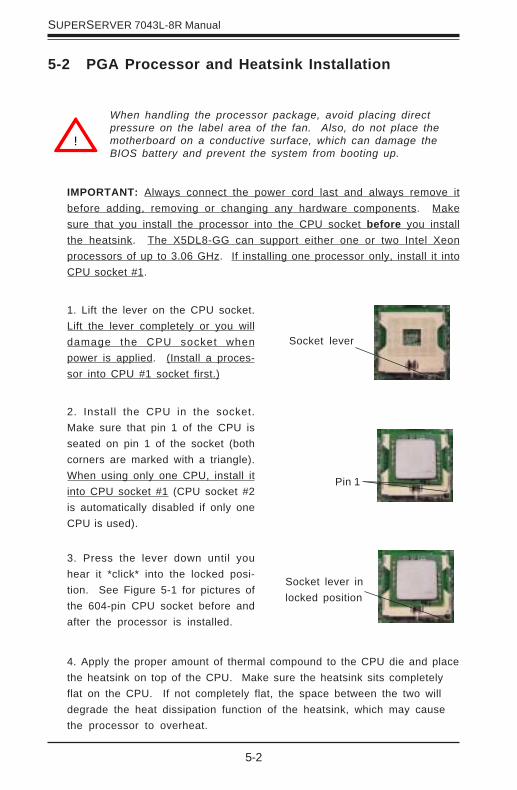
1. Lift the lever on the CPU socket.Lift the lever completely or you willdamage the CPU socket whenpower is applied. (Install a proces-sor into CPU #1 socket first.)
2. Install the CPU in the socket.Make sure that pin 1 of the CPU isseated on pin 1 of the socket (bothcorners are marked with a triangle).When using only one CPU, install itinto CPU socket #1 (CPU socket #2is automatically disabled if only oneCPU is used).
3. Press the lever down until youhear it *click* into the locked posi-tion. See Figure 5-1 for pictures ofthe 604-pin CPU socket before andafter the processor is installed.
4. Apply the proper amount of thermal compound to the CPU die and placethe heatsink on top of the CPU. Make sure the heatsink sits completelyflat on the CPU. If not completely flat, the space between the two willdegrade the heat dissipation function of the heatsink, which may causethe processor to overheat.
Socket lever
Pin 1
Socket lever inlocked position
Chapter 5: Advanced Motherboard Setup
5-3
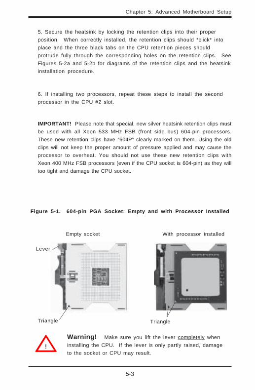
Figure 5-1. 604-pin PGA Socket: Empty and with Processor Installed
Warning! Make sure you lift the lever completely wheninstalling the CPU. If the lever is only partly raised, damageto the socket or CPU may result.
!
Lever
With processor installed
Triangle Triangle
Empty socket
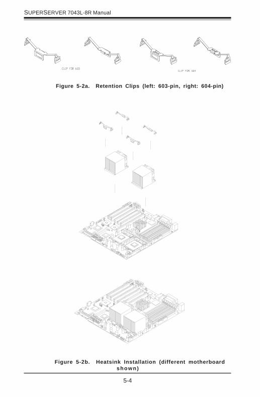
5. Secure the heatsink by locking the retention clips into their properposition. When correctly installed, the retention clips should *click* intoplace and the three black tabs on the CPU retention pieces shouldprotrude fully through the corresponding holes on the retention clips. SeeFigures 5-2a and 5-2b for diagrams of the retention clips and the heatsinkinstallation procedure.
6. If installing two processors, repeat these steps to install the secondprocessor in the CPU #2 slot.
IMPORTANT! Please note that special, new silver heatsink retention clips mustbe used with all Xeon 533 MHz FSB (front side bus) 604-pin processors.These new retention clips have “604P” clearly marked on them. Using the oldclips will not keep the proper amount of pressure applied and may cause theprocessor to overheat. You should not use these new retention clips withXeon 400 MHz FSB processors (even if the CPU socket is 604-pin) as they willtoo tight and damage the CPU socket.
5-4
SUPERSERVER 7043L-8R Manual
Figure 5-2b. Heatsink Installation (different motherboardshown)
Figure 5-2a. Retention Clips (left: 603-pin, right: 604-pin)

Chapter 5: Advanced Motherboard Setup
5-5
5-3 Connecting Cables
Now that the processors are installed, the next step is to connect thecables to the board. These include the data (ribbon) cables for the periph-erals and control panel and the power cables.
Connecting Data Cables
The ribbon cables used to transfer data from the peripheral devices havebeen carefully routed in preconfigured systems to prevent them from block-ing the flow of cooling air that moves through the system from front to back.If you need to disconnect any of these cables, you should take care to keepthem routed as they were originally after reconnecting them (make sure thered wires connect to the pin 1 locations). If you are configuring the sys-tem, keep the airflow in mind when routing the cables. The following datacables (with their motherboard connector locations noted) should be con-nected. See the motherboard layout figure in this chapter for connectorlocations.
! IDE Device Cables (J18, J19)
! Floppy Drive Cable (J12)
! Ultra 320 LVD SCSI Cables (JA1, JA2)
! Control Panel Cable (JF1, JF2 is optional, see next page)
Connecting Power Cables
The X5DL8-GG has a 24-pin primary power supply connector designated"ATX Power" for connection to the ATX power supply. Connect the appro-priate connector from the power supply to the "ATX Power" connector tosupply power to the motherboard. The Processor Power Connector (atJ56) must also be connected to your power supply. See the ConnectorDefinitions section in this chapter for power connector pin definitions.

5-6
SUPERSERVER 7043L-8R Manual
Figure 5-3. JF1/JF2 Header Pins
Connecting the Control Panel
JF1 contains header pins for various front control panel connectors. SeeFigure 5-3 for the pin locations of the various front control panel buttonsand LED indicators. All JF1 wires have been bundled into single ribboncable to simplify their connection. Make sure the red wire plugs into pin 1as marked on the motherboard. The other end connects to the Control Panelprinted circuit board, located just behind the system status LEDs in thechassis. See the Connector Definitions section in this chapter for detailsand pin descriptions of JF1.
JF2 is an additional row of headers that provides connectors for additionalfunctions, as noted below.
12
HD LED
1516
Power LED
X
Chassis Intrusion
Speaker
JF2
Power Button
Overheat LED
1
NIC1 LED
Reset Button
2
Power Fail LED
NIC2 LED
HDD LED
Power LED
Reset
Pwr
Vcc
Vcc
Vcc
Vcc
Vcc
Ground
Ground
1920
Vcc
X
Ground NMI
X
JF1

Chapter 5: Advanced Motherboard Setup
5-7
5-4 I/O Ports
The I/O ports are color coded in conformance with the PC 99 specification.See Figure 5-4 below for the colors and locations of the various I/O ports.
Figure 5-4. Rear Panel IO Port Locations and Definitions
5-5 Installing Memory
Note: Check the Supermicro web site for recommended memory modules:
http://www.supermicro.com/TECHSUPPORT/FAQs/Memory_vendors.htm
CAUTIONExercise extreme care when installing or removing DIMM
modules to prevent any possible damage. Also note that thememory is interleaved to improve performance (see step 1).
DIMM Installation (See Figure 2-2)
1. Insert an even number of memory modules. Interleaved memory requiresyou to install two modules at a time. With the X5DL8-GG, begin fromthe two slots of the last bank and work your way toward the two slotsof Bank 1.
2. Insert each DIMM module vertically into its slot. Pay attention to thenotch along the bottom of the module to prevent inserting the DIMMmodule incorrectly.
3. Gently press down on the DIMM module until it snaps into place in theslot. Repeat for all modules (see step 1 above).
Parallel Port (Burgundy)Mouse
(Green)
Keyboard
(Purple)
USB Ports COM1 Port
(Turquoise)
GLAN1 GLAN2VGA (Monitor) Port
(Blue)
5-8
SUPERSERVER 7043L-8R Manual
Figure 5-5b. Top View of DIMM Slot
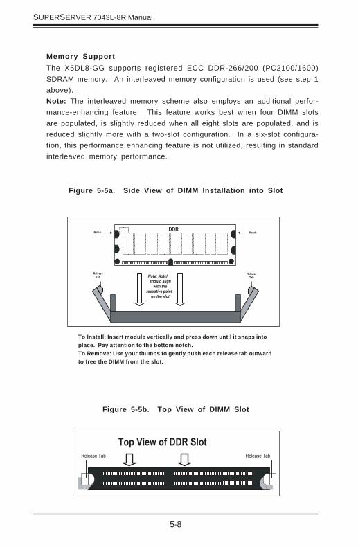
Figure 5-5a. Side View of DIMM Installation into Slot
To Install: Insert module vertically and press down until it snaps intoplace. Pay attention to the bottom notch.To Remove: Use your thumbs to gently push each release tab outwardto free the DIMM from the slot.
Memory SupportThe X5DL8-GG supports registered ECC DDR-266/200 (PC2100/1600)SDRAM memory. An interleaved memory configuration is used (see step 1above).Note: The interleaved memory scheme also employs an additional perfor-mance-enhancing feature. This feature works best when four DIMM slotsare populated, is slightly reduced when all eight slots are populated, and isreduced slightly more with a two-slot configuration. In a six-slot configura-tion, this performance enhancing feature is not utilized, resulting in standardinterleaved memory performance.

Chapter 5: Advanced Motherboard Setup
5-9
5-6 Adding PCI Cards
1. PCI expansion slots:The X5DL8-GG system board has six 64-bit PCI-X slots. A maximum ofthree may be set for 133 MHz operation (the default setting is all slots at100 MHz.) The backplane of the 7043L-8R has seven I/O slots that allowyou to have a full complement of PCI cards installed on the system.
2. PCI card installation:Before installing a PCI add-on card, make sure you choose the correctslot for the type of card you are installing (see step 1 above). Begin byremoving the I/O shield from the backplane of the server corresponding tothe PCI slot you wish to populate. Insert the card into the slot on themotherboard, pushing down with your thumbs evenly on both sides of thecard. Finish by using a screw to secure the top of the card shield to thechassis. The I/O shields protect the motherboard and its componentsfrom EMI (electromagnetic interference) and aid in proper ventilation ofthe server, so make sure there is always a shield covering each slot.

5-10
SUPERSERVER 7043L-8R Manual
Figure 5-7. SUPER X5DL8-GG Layout(not drawn to scale)
5-7 Motherboard Details
1234567890123456789012312345678901234567890123
J11 Keyboard/Mouse
J66
ATX POWER
GLAN1
USB0/1
Rage XL
J55
COM1
VGA
GLAN2
CPU1
CPU2NorthBridge
BATTERY
J56
Bank 1ABank 1BBank 2A
Bank 2B
Bank 3A
Bank 3B
Bank 4ABank 4B
ParallelPort
J65
D5-D8
COM2
D1-D4
SouthBridge
BroadcomController
SUPER X5DL8-GG®
J12 J19 J18
IDE
#2
IDE
#1
FLO
PPY
PCI-X #6
PCI-X #5
PCI-X #4
PCI-X #1
PCI-X #2
PCI-X #3
BIOS
AIC-7902
Ultr
a III
LVD
/SE
ChB
IPM
I
JP54
SW4 Ultra III LVD/SE ChA
IO Bridge
JF1
CPU2/CHS FAN
CPU2 FAN
CPU1 FAN
CPU1/CHS FAN
OH/CHS FAN
JF2
IO Bridge
JP48
JP7
JP4
JP56
JBT1
S1P1
P2S2
WOL
JP2
J29
J1
JA4
JPA1
CHS FAN
JPA2
CR5
JP58
JP57
J35
J20
J21
JP3
JA2
JA1
JP12
Note: DIP Switch 4 sets the processor speed (see Section 5-10). CR5 is a power LED indicator (see Section 5-9).
Jumpers not noted are for test purposes only.IPMI is optional.
The 8-pin, 12v Processor Power connector at J56 must also beconnected to your power supply.
Chapter 5: Advanced Motherboard Setup
5-11
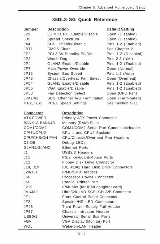
X5DL8-GG Quick Reference
Jumper Description Default SettingJ29 33 MHz PCI Enable/Disable Open (Disabled)J35 Spread Spectrum Open (Disabled)JA4 SCSI Enable/Disable Pins 1-2 (Enabled)JBT1 CMOS Clear See Chapter 2JP2 PCI 3.3V Standby En/Dis Pins 1-2 (Disabled)JP3 Watch Dog Pins 2-3 (NMI)JP4 GLAN2 Enable/Disable Pins 1-2 (Enabled)JP7 Main Power Override Open (Normal)JP12 System Bus Speed Pins 1-2 (Auto)JP48 Chassis/Overheat Fan Select Open (Overheat)JP54 GLAN1 Enable/Disable Pins 1-2 (Enabled)JP56 VGA Enable/Disable Pins 1-2 (Enabled)JP58 Fan Detection Select Open (CPU Fan)JPA1/A2 SCSI Channel A/B Termination Open (Terminated)P1/2, S1/2 PCI-X Speed Settings See Section 5-11
Connector DescriptionATX POWER Primary ATX Power ConnectorBANK1A-BANK4B Memory (RAM) SlotsCOM1/COM2 COM1/COM2 Serial Port Connector/HeaderCPU1/CPU2 CPU 1 and CPU2 SocketsCPU/CHS/OH FAN CPU/Chassis/Overheat Fan HeadersD1-D8 Debug LEDsGLAN1/GLAN2 Ethernet PortsJ1 USB2/3 HeadersJ11 PS/2 Keyboard/Mouse PortsJ12 Floppy Disk Drive ConnectorJ18, J19 IDE #1/#2 Hard Disk Drive ConnectorsJ20/J21 IPMB/SMB HeadersJ56 Processor Power ConnectorJ65 Parallel Printer PortJ219 IPMI Slot (for IPMI daughter card)JA1/JA2 Ultra320 LVD SCSI CH A/B ConnectorJF1 Front Control Panel ConnectorJF2 Speaker/HD LED ConnectorsJP46 Third Power Supply Fail HeaderJP57 Chassis Intrusion HeaderUSB0/1 Universal Serial Bus PortsVGA VGA Display (Monitor) PortWOL Wake-on-LAN Header
5-12
SUPERSERVER 7043L-8R Manual
5-8 Connector Definitions
PinNumber
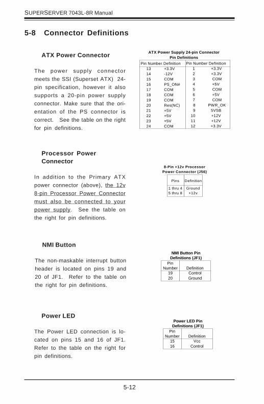
1516
DefinitionVcc
Control
Power LED PinDefinitions (JF1)
NMI Button
The non-maskable interrupt buttonheader is located on pins 19 and20 of JF1. Refer to the table onthe right for pin definitions.
PinNumber
1920
DefinitionControlGround
NMI Button PinDefinitions (JF1)
ATX Power Supply 24-pin ConnectorPin Definitions
Pin Number Definition 13 +3.3V 14 -12V 15 COM 16 PS_ON# 17 COM 18 COM 19 COM 20 Res(NC) 21 +5V 22 +5V 23 +5V 24 COM
Pin Number Definition 1 +3.3V 2 +3.3V 3 COM
4 +5V 5 COM
6 +5V 7 COM
8 PWR_OK 9 5VSB 10 +12V 11 +12V 12 +3.3V
ATX Power Connector
The power supply connectormeets the SSI (Superset ATX) 24-pin specification, however it alsosupports a 20-pin power supplyconnector. Make sure that the ori-entation of the PS connector iscorrect. See the table on the rightfor pin definitions.
Pins
1 thru 45 thru 8
Definition
Ground+12v
8-Pin +12v ProcessorPower Connector (J56)
Processor PowerConnector
In addition to the Primary ATXpower connector (above), the 12v8-pin Processor Power Connectormust also be connected to yourpower supply. See the table onthe right for pin definitions.
Power LED
The Power LED connection is lo-cated on pins 15 and 16 of JF1.Refer to the table on the right forpin definitions.

Chapter 5: Advanced Motherboard Setup
5-13
Overheat LED (OH)
Connect an LED to the OH connec-tion on pins 7 and 8 of JF1 to pro-vide advanced warning of chassisoverheating. Refer to the table onthe right for pin definitions.
NIC1 LED
The NIC1 (LAN1) LED connectionis located on pins 11 and 12 ofJF1. Attach the NIC1 LED cable todisplay network activity. Refer tothe table on the right for pin defini-tions.
NIC/LAN2 LEDPin Definitions
(JF1)
PinNumber
910
Definition+5VGND
Overheat (OH) LEDPin Definitions
(JF1)
PinNumber
78
Definition+5VGND
NIC2 LED
The NIC2 (LAN2) LED connectionis located on pins 9 and 10 of JF1.Attach the NIC2 LED cable to dis-play network activity. Refer to thetable on the right for pin defini-tions.
NIC/LAN1 LED Pin Definitions
(JF1)
PinNumber
1112
Definition+5VGND
HDD LED
The HDD LED (for IDE and SCSIdisk drives) connection is locatedon pins 13 and 14 of JF1. Attachthe IDE hard drive LED cable tothese pins to display disk activity.Refer to the table on the right forpin definitions.
(IDE) HDD LED PinDefinitions
(JF1)
PinNumber
1314
Definition+5V
HD Active
Power Fail LED
The Power Fail LED connection islocated on pins 5 and 6 of JF1.Refer to the table on the right forpin definitions.
Power Fail LED PinDefinitions
(JF1)
PinNumber
56
DefinitionControl
GND
5-14
SUPERSERVER 7043L-8R Manual
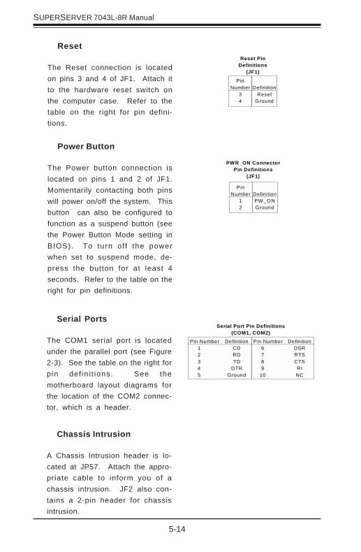
Power Button
The Power button connection islocated on pins 1 and 2 of JF1.Momentarily contacting both pinswill power on/off the system. Thisbutton can also be configured tofunction as a suspend button (seethe Power Button Mode setting inBIOS). To turn off the powerwhen set to suspend mode, de-press the button for at least 4seconds. Refer to the table on theright for pin definitions.
PinNumber
12
DefinitionPW _ONGround
PWR_ON ConnectorPin Definitions
(JF1)
Reset
The Reset connection is locatedon pins 3 and 4 of JF1. Attach itto the hardware reset switch onthe computer case. Refer to thetable on the right for pin defini-tions.
PinNumber
34
DefinitionReset
Ground
Reset PinDefinitions
(JF1)
Serial Ports
The COM1 serial port is locatedunder the parallel port (see Figure2-3). See the table on the right forpin def in i t ions. See themotherboard layout diagrams forthe location of the COM2 connec-tor, which is a header.
Serial Port Pin Definitions(COM1, COM2)
Pin Number Definition 1 CD 2 RD 3 TD 4 DTR 5 Ground
Pin Number Definition 6 DSR 7 RTS 8 CTS 9 RI 10 NC
Chassis Intrusion
A Chassis Intrusion header is lo-cated at JP57. Attach the appro-priate cable to inform you of achassis intrusion. JF2 also con-tains a 2-pin header for chassisintrusion.
Chapter 5: Advanced Motherboard Setup
5-15
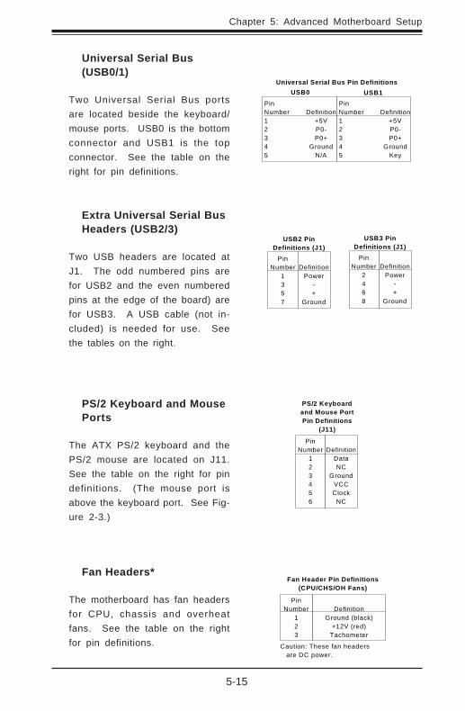
Universal Serial Bus(USB0/1)
Two Universal Serial Bus portsare located beside the keyboard/mouse ports. USB0 is the bottomconnector and USB1 is the topconnector. See the table on theright for pin definitions.
Universal Serial Bus Pin Definitions
Pin Number Definition 1 +5V 2 P0- 3 P0+ 4 Ground 5 N/A
Pin Number Definition 1 +5V 2 P0- 3 P0+ 4 Ground 5 Key
USB0 USB1
PS/2 Keyboard and MousePorts
The ATX PS/2 keyboard and thePS/2 mouse are located on J11.See the table on the right for pindefinitions. (The mouse port isabove the keyboard port. See Fig-ure 2-3.)
PS/2 Keyboardand Mouse PortPin Definitions
(J11)
PinNumber
123456
DefinitionDataNC
GroundVCCClock
NC
Fan Header Pin Definitions(CPU/CHS/OH Fans)
PinNumber
123
DefinitionGround (black)
+12V (red)Tachometer
Caution: These fan headers are DC power.
Fan Headers*
The motherboard has fan headersfor CPU, chassis and overheatfans. See the table on the rightfor pin definitions.
Extra Universal Serial BusHeaders (USB2/3)
Two USB headers are located atJ1. The odd numbered pins arefor USB2 and the even numberedpins at the edge of the board) arefor USB3. A USB cable (not in-cluded) is needed for use. Seethe tables on the right.
PinNumber
1357
DefinitionPower
-+
Ground
USB2 PinDefinitions (J1)
PinNumber
2468
DefinitionPower
-+
Ground
USB3 PinDefinitions (J1)
5-16
SUPERSERVER 7043L-8R Manual
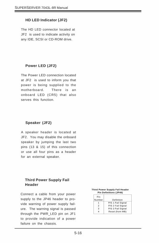
HD LED Indicator (JF2)
The HD LED connector located atJF2 is used to indicate activity onany IDE, SCSI or CD-ROM drive.
Speaker (JF2)
A speaker header is located atJF2. You may disable the onboardspeaker by jumping the last twopins (13 & 15) of this connectionor use all four pins as a headerfor an external speaker.
Power LED (JF2)
The Power LED connection locatedat JF2 is used to inform you thatpower is being supplied to themotherboard. There is anonboard LED (CR5) that alsoserves this function.
Third Power Supply FailHeader
Connect a cable from your powersupply to the JP46 header to pro-vide warning of power supply fail-ure. The warning signal is passedthrough the PWR_LED pin on JF1to provide indication of a powerfailure on the chassis.
Third Power Supply Fail HeaderPin Definitions (JP46)
PinNumber
1234
DefinitionP/S 1 Fail SignalP/S 2 Fail SignalP/S 3 Fail SignalReset (from MB)

Chapter 5: Advanced Motherboard Setup
5-17
SMB
A System Management Busheader is located at J21. Connectthe appropriate cable here to uti-lize SMB on your system.
PinNumber
123
Definition+5V Standby
GroundW ake-up
Wake-On-LAN PinDefinitions (WOL)
Wake-On-LAN
The Wake-On-LAN header is des-ignated as WOL. See the table onthe right for pin definitions. Youmust have a LAN card with aWake-on-LAN connector and cableto use this feature.
IPMB
An IPMB (IPMI Bus) header is lo-cated at J20 to support IPMI, aserver management standard.Connect the appropr iate cablefrom the IPMI daughter board toJ20 to utilize IPMI on your system.
IPMB HeaderPin Definitions (J20)
PinNumber
1234
DefinitionData
GroundClock
No Connection
SMB HeaderPin Definitions (J21)
PinNumber
1234
DefinitionData
GroundClock
No Connection
GLAN1/GLAN2 EthernetPorts
Two gigabit Ethernet ports are lo-cated beside the VGA port on theIO backplane. These ports acceptRJ45 type cables. See the nextsection for a description of theLEDs on the LAN ports.
5-18
SUPERSERVER 7043L-8R Manual
LEDColor
OffYellow
DefinitionNot Active
Active
Gb LAN Left LEDIndicator
5-9 Onboard Indicators
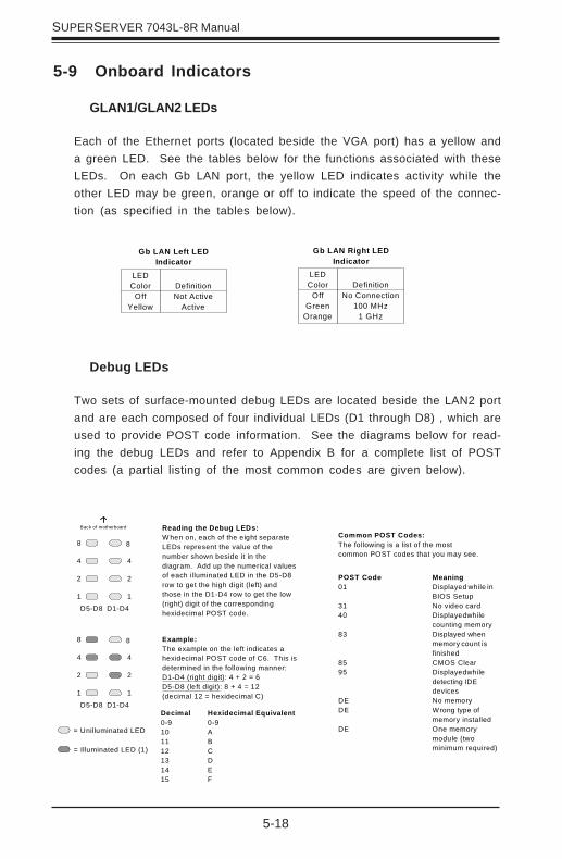
GLAN1/GLAN2 LEDs
Each of the Ethernet ports (located beside the VGA port) has a yellow anda green LED. See the tables below for the functions associated with theseLEDs. On each Gb LAN port, the yellow LED indicates activity while theother LED may be green, orange or off to indicate the speed of the connec-tion (as specified in the tables below).
Debug LEDs
Two sets of surface-mounted debug LEDs are located beside the LAN2 portand are each composed of four individual LEDs (D1 through D8) , which areused to provide POST code information. See the diagrams below for read-ing the debug LEDs and refer to Appendix B for a complete list of POSTcodes (a partial listing of the most common codes are given below).
LEDColor
OffGreen
Orange
DefinitionNo Connection
100 MHz1 GHz
Gb LAN Right LEDIndicator
D5-D8
8
2
1
8
2
1
44
D1-D4
Reading the Debug LEDs:W hen on, each of the eight separateLEDs represent the value of thenumber shown beside it in thediagram. Add up the numerical valuesof each illuminated LED in the D5-D8row to get the high digit (left) andthose in the D1-D4 row to get the low(right) digit of the correspondinghexidecimal POST code.
Example:The example on the left indicates ahexidecimal POST code of C6. This isdetermined in the following manner:D1-D4 (right digit): 4 + 2 = 6D5-D8 (left digit): 8 + 4 = 12(decimal 12 = hexidecimal C)
Decimal Hexidecimal Equivalent0-9 0-910 A11 B12 C13 D14 E15 F
= Unilluminated LED
Back of motherboard
D5-D8
8
2
1
8
2
1
44
D1-D4
= Illuminated LED (1)
Common POST Codes:The following is a list of the mostcommon POST codes that you may see.
POST Code Meaning01 Displayed while in
BIOS Setup31 No video card40 Displayed while
counting memory83 Displayed when
memory count is finished
85 CMOS Clear95 Displayed while
detecting IDE devices
DE No memoryDE Wrong type of
memory installedDE One memory
module (twominimum required)
Chapter 5: Advanced Motherboard Setup
5-19
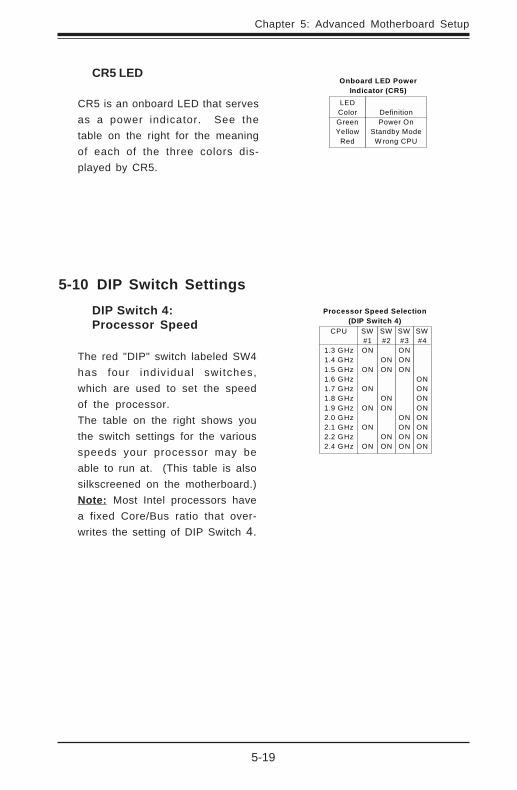
5-10 DIP Switch SettingsDIP Switch 4:Processor Speed
The red "DIP" switch labeled SW4has four indiv idual switches,which are used to set the speedof the processor.The table on the right shows youthe switch settings for the variousspeeds your processor may beable to run at. (This table is alsosilkscreened on the motherboard.)Note: Most Intel processors havea fixed Core/Bus ratio that over-writes the setting of DIP Switch 4.
SW#3ONONON
ONONONON
CPU
1.3 GHz1.4 GHz1.5 GHz1.6 GHz1.7 GHz1.8 GHz1.9 GHz2.0 GHz2.1 GHz2.2 GHz2.4 GHz
SW#1ON
ON
ON
ON
ON
ON
SW#2
ONON
ONON
ONON
SW#4
ONONONONONONONON
Processor Speed Selection(DIP Switch 4)
CR5 LED
CR5 is an onboard LED that servesas a power indicator. See thetable on the right for the meaningof each of the three colors dis-played by CR5.
LEDColorGreenYellow
Red
DefinitionPower On
Standby ModeW rong CPU
Onboard LED PowerIndicator (CR5)

5-20
SUPERSERVER 7043L-8R Manual
5-11 Jumper Settings
Explanation ofJumpers
To modify the operat ion of themotherboard, jumpers can be used tochoose between optional sett ings.Jumpers create shorts between twopins to change the function of theconnector. Pin 1 is identified with asquare solder pad on the pr intedcircuit board. See the motherboardlayout pages for jumper locations.Note: On two pin jumpers, "Closed"means the jumper is on and "Open"means the jumper is off the pins.
ConnectorPins
JumperCap
Setting
Pin 1-2 short
3 2 1
3 2 1
CMOS Clear
JBT1 is used to clear CMOS. Instead of pins, this jumper consists of con-tact pads to prevent accidentally clearing the contents of CMOS.To clear CMOS, 1) First unplug the power cord(s) 2) With the power discon-nected, short the CMOS pads with a metal object such as a small screw-driver 3) Remove the screwdriver (or shorting device) 4) Reconnect thepower cord(s) and power on the system.Note: Do not use the PW_ON connector to clear CMOS.
Main Power Override
Instead of using the chassis poweron switch, you may close jumper JP7to apply power to the system. Thiseffectively disables the power buttonfrom turning off the system. See thetable on the right for jumper settings.The default setting is Open (normal).
JumperPosition
OpenClosed
DefinitionNormal
Force Power On
Power OnJumper Settings
(JP1)
Chapter 5: Advanced Motherboard Setup
5-21
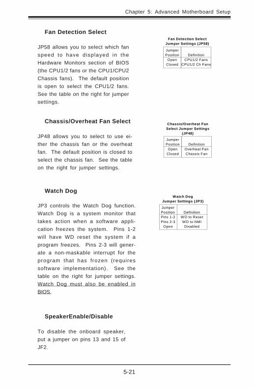
SpeakerEnable/Disable
To disable the onboard speaker,put a jumper on pins 13 and 15 ofJF2.
Chassis/Overheat Fan Select
JP48 allows you to select to use ei-ther the chassis fan or the overheatfan. The default position is closed toselect the chassis fan. See the tableon the right for jumper settings.
JumperPosition
OpenClosed
DefinitionOverheat FanChassis Fan
Chassis/Overheat FanSelect Jumper Settings
(JP48)
Fan Detection Select
JP58 allows you to select which fanspeed to have displayed in theHardware Monitors section of BIOS(the CPU1/2 fans or the CPU1/CPU2Chassis fans). The default positionis open to select the CPU1/2 fans.See the table on the right for jumpersettings.
JumperPosition
OpenClosed
DefinitionCPU1/2 Fans
CPU1/2 Ch Fans
Fan Detection SelectJumper Settings (JP58)
Watch Dog
JP3 controls the Watch Dog function.Watch Dog is a system monitor thattakes action when a software appli-cation freezes the system. Pins 1-2will have WD reset the system if aprogram freezes. Pins 2-3 will gener-ate a non-maskable interrupt for theprogram that has frozen (requiressoftware implementation). See thetable on the right for jumper settings.Watch Dog must also be enabled inBIOS.
JumperPositionPins 1-2Pins 2-3
Open
DefinitionW D to ResetW D to NMIDisabled
Watch DogJumper Settings (JP3)
5-22
SUPERSERVER 7043L-8R Manual
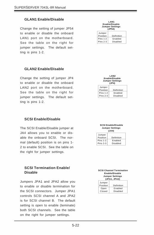
GLAN1 Enable/Disable
Change the setting of jumper JP54to enable or disable the onboardLAN1 port on the motherboard.See the table on the r ight forjumper settings. The default set-ting is pins 1-2.
JumperPositionPins 1-2Pins 2-3
DefinitionEnabledDisabled
LAN1Enable/Disable
Jumper Settings(JP54)
GLAN2 Enable/Disable
Change the setting of jumper JP4to enable or disable the onboardLAN2 port on the motherboard.See the table on the r ight forjumper settings. The default set-ting is pins 1-2.
JumperPositionPins 1-2Pins 2-3
DefinitionEnabledDisabled
LAN2Enable/Disable
Jumper Settings(JP4)
SCSI Enable/Disable
The SCSI Enable/Disable jumper atJA4 allows you to enable or dis-able the onboard SCSI. The nor-mal (default) position is on pins 1-2 to enable SCSI. See the table onthe right for jumper settings.
JumperPositionPins 1-2Pins 2-3
DefinitionEnabledDisabled
SCSI Enable/DisableJumper Settings
(JA4)
SCSI Termination Enable/Disable
Jumpers JPA1 and JPA2 allow youto enable or disable termination forthe SCSI connectors. Jumper JPA1controls SCSI channel A and JPA2is for SCSI channel B. The defaultsetting is open to enable (teminate)both SCSI channels. See the tableon the right for jumper settings.
JumperPosition
OpenClosed
DefinitionEnabledDisabled
SCSI Channel TerminationEnable/Disable
Jumper Settings(JPA1, JPA2)

Chapter 5: Advanced Motherboard Setup
5-23
33 MHz PCI Enable/Disable
I f you wish to use 33 MHz PCIcards, close J29 to force the P1bus (slots 2 & 3) to run at 33 MHz.See the table on the right for jumpersettings.Note: if you force the slots(s) to 33MHz, you must set the P1 busspeed jumpers (above) to the low-est speed.
JumperPosition
OpenClosed
DefinitionNormal
33 MHz PCI
33 MHz PCIEnable/Disable
Jumper Settings(J29)
PCI-X Slot Bus Speed Settings Pin Definitions(P1, P2, S1, S2)
PinSetting
Pins 1-2Pins 2-3Pins 3-4Pins 4-5
SpeedPCI 33/66 MHzPCI-X 66 MHz
PCI-X 100 MHzPCI-X 133 MHz
Default setting is PCI-X 100 MHz for all
slots.
PCI-X Bus Speed Setting
Jumpers P1, P2, S1 and S2 areused to change the speeds for thefour PCI-X buses. See the table onthe right for jumper settings.PCI-X Buses:S1: Bus for PCI-X slot #1 and SCSIP1: Bus for PCI-X slots #2 and #3S2: Bus for PCI-X slots #4 and #5P2: Bus for PCI-X slot #6 and LAN2Note: If two cards are used in slotsthat share a bus, both slots will runat 100 MHz (maximum).
PCI 3.3V Standby Enable/Disable
JP2 is used to enable or disable a3.3V standby voltage on pin A14of the PCI-X slots. If you have aLAN or modem add-on card in-serted into a PCI-X slot that youwish to "wake" the system upwith, you should enable thisjumper. Otherwise, leave thisjumper on pins 1-2 (disabled).The normal (default) position isdisabled. See the table on theright for jumper settings.
JumperPositionPins 1-2Pins 2-3
DefinitionDisabledEnabled
PCI 3.3V Standby Enable/Disable Jumper Settings
(JP2)
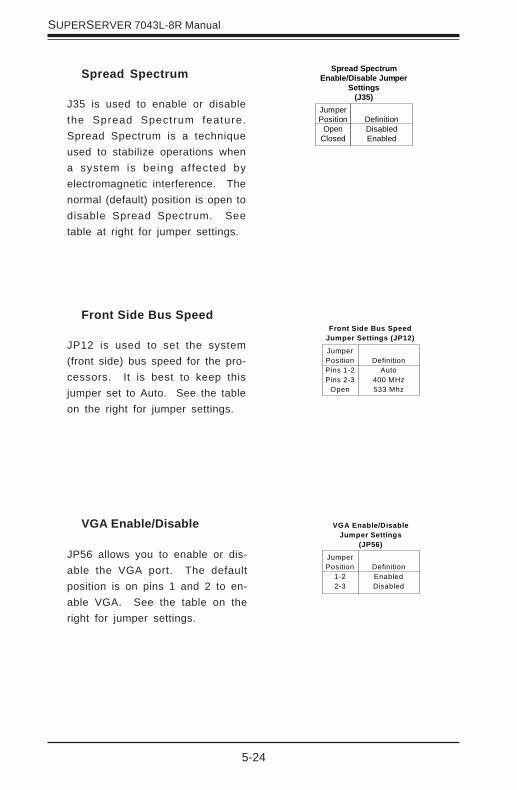
5-24
SUPERSERVER 7043L-8R Manual
Spread Spectrum
J35 is used to enable or disablethe Spread Spectrum feature.Spread Spectrum is a techniqueused to stabilize operations whena system is being af fected byelectromagnetic interference. Thenormal (default) position is open todisable Spread Spectrum. Seetable at right for jumper settings.
JumperPosition
OpenClosed
DefinitionDisabledEnabled
Spread SpectrumEnable/Disable Jumper
Settings(J35)
VGA Enable/Disable
JP56 allows you to enable or dis-able the VGA port. The defaultposition is on pins 1 and 2 to en-able VGA. See the table on theright for jumper settings.
JumperPosition
1-22-3
DefinitionEnabledDisabled
VGA Enable/DisableJumper Settings
(JP56)
Front Side Bus Speed
JP12 is used to set the system(front side) bus speed for the pro-cessors. It is best to keep thisjumper set to Auto. See the tableon the right for jumper settings.
JumperPositionPins 1-2Pins 2-3
Open
DefinitionAuto
400 MHz533 Mhz
Front Side Bus SpeedJumper Settings (JP12)
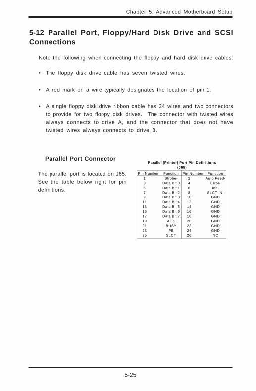
Chapter 5: Advanced Motherboard Setup
5-25
5-12 Parallel Port, Floppy/Hard Disk Drive and SCSIConnections
Note the following when connecting the floppy and hard disk drive cables:
• The floppy disk drive cable has seven twisted wires.
• A red mark on a wire typically designates the location of pin 1.
• A single floppy disk drive ribbon cable has 34 wires and two connectorsto provide for two floppy disk drives. The connector with twisted wiresalways connects to drive A, and the connector that does not havetwisted wires always connects to drive B.
Parallel Port Connector
The parallel port is located on J65.See the table below right for pindefinitions.
Pin Number Function 1 Strobe- 3 Data Bit 0 5 Data Bit 1 7 Data Bit 2 9 Data Bit 3 11 Data Bit 4 13 Data Bit 5 15 Data Bit 6 17 Data Bit 7 19 ACK 21 BUSY 23 PE 25 SLCT
Pin Number Function 2 Auto Feed- 4 Error- 6 Init- 8 SLCT IN- 10 GND 12 GND 14 GND 16 GND 18 GND 20 GND 22 GND 24 GND 26 NC
Parallel (Printer) Port Pin Definitions(J65)
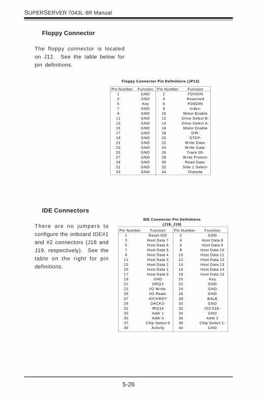
5-26
SUPERSERVER 7043L-8R Manual
IDE Connectors
There are no jumpers toconfigure the onboard IDE#1and #2 connectors (J18 andJ19, respectively). See thetable on the right for pindefinitions.
Floppy Connector
The floppy connector is locatedon J12. See the table below forpin definitions.
Pin Number Function 1 GND 3 GND 5 Key 7 GND 9 GND 11 GND 13 GND 15 GND 17 GND 19 GND 21 GND 23 GND 25 GND 27 GND 29 GND 31 GND 33 GND
Pin Number Function 2 FDHDIN 4 Reserved 6 FDEDIN 8 Index- 10 Motor Enable 12 Drive Select B- 14 Drive Select A- 16 Motor Enable 18 DIR- 20 STEP- 22 W rite Data- 24 W rite Gate- 26 Track 00- 28 W rite Protect- 30 Read Data- 32 Side 1 Select- 34 Diskette
Floppy Connector Pin Definitions (JP12)
Pin Number Function 1 Reset IDE 3 Host Data 7 5 Host Data 6 7 Host Data 5 9 Host Data 4 11 Host Data 3 13 Host Data 2 15 Host Data 1 17 Host Data 0 19 GND 21 DRQ3 23 I/O W rite- 25 I/O Read- 27 IOCHRDY 29 DACK3- 31 IRQ14 33 Addr 1 35 Addr 0 37 Chip Select 0 39 Activity
Pin Number Function 2 GND 4 Host Data 8 6 Host Data 9 8 Host Data 10 10 Host Data 11 12 Host Data 12 14 Host Data 13 16 Host Data 14 18 Host Data 15 20 Key 22 GND 24 GND 26 GND 28 BALE 30 GND 32 IOCS16- 34 GND 36 Addr 2 38 Chip Select 1- 40 GND
IDE Connector Pin Definitions(J18, J19)
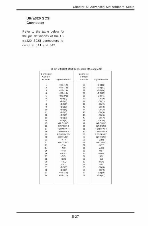
Chapter 5: Advanced Motherboard Setup
5-27
Signal Names
+DB(12)+DB(13)+DB(14)+DB(15)+DB(P1)+DB(0)+DB(1)+DB(2)+DB(3)+DB(4)+DB(5)+DB(6)+DB(7)+DB(P)
GROUNDDIFFSENSTERMPW RTERMPW RRESERVED
GROUND+ATN
GROUND+BSY+ACK+RST+MSG+SEL+C/D+REQ+I/O
+DB(8)+DB(9)
+DB(10)+DB(11)
ConnectorContactNumber
123456789
10111213141516171819202122232425262728293031323334
Signal Names
-DB(12)-DB(13)-DB(14)-DB(15)-DB(P1)-DB(0)-DB(1)-DB(2)-DB(3)-DB(4)-DB(5)-DB(6)-DB(7)-DB(P)
GROUNDGROUND
TERMPW RTERMPW RRESERVED
GROUND-ATN
GROUND-BSY-ACK-RST-MSG-SEL-C/D-REQ-I/O
-DB(8)-DB(9)
-DB(10)-DB(11)
ConnectorContactNumber
35363738394041424344454647484950515253545556575859606162636465666768
68-pin Ultra320 SCSI Connectors (JA1 and JA2)
Ultra320 SCSIConnector
Refer to the table below forthe pin definitions of the Ul-tra320 SCSI connectors lo-cated at JA1 and JA2.

5-28
SUPERSERVER 7043L-8R Manual
5-13 Installing Software Drivers
After all the hardware has been installed you must install the softwaredrivers. The necessary drivers are all included on the Supermicro CD thatcame packaged with your motherboard. After inserting this CD into yourCDROM drive, the display shown in Figure 2-5 should appear. (If this dis-play does not appear, click on the My Computer icon and then on the iconrepresenting your CDROM drive. Finally, double click on the S "Setup" icon.)
Figure 2-5. Driver/Tool Installation Display Screen
Click the icons showing a hand writing on paper to view the readme filesfor each item. The bottom icon with a CD on it allows you to view theentire contents of the CD.
Chapter 6: Advanced Chassis Setup
6-1
Chapter 6
Advanced Chassis Setup
This chapter covers the steps required to install components and performsimple maintenance on the SC742 chassis. Following the component instal-lation steps in the order given will eliminate most common problems. If somesteps are unnecessary, skip ahead to the step that follows. Refer to Chap-ter 2 for instructions on installing the system as a 4U rackmount.
Tools RequiredThe only tool you will need is a Philips screwdriver.
6-1 Static-Sensitive Devices
Static electrical discharge can damage electronic components. To preventdamage to any printed circuit boards (PCBs), it is important to handle themvery carefully. The following measures are generally sufficient to protect yourequipment from static discharge.
Precautions
• Use a grounded wrist strap designed to prevent static discharge.• Touch a grounded metal object before removing any board from its anti-
static bag.• Handle a board by its edges only; do not touch its components, peripheral
chips, memory modules or gold contacts.• When handling chips or modules, avoid touching their pins.• Put the motherboard, add-on cards and peripherals back into their anti-
static bags when not in use.• For grounding purposes, make sure your computer chassis provides excel-
lent conductivity between the power supply, the case, the mounting fasten-ers and the motherboard.
Unpacking
The motherboard is shipped in antistatic packaging. When unpacking theboard, make sure the person handling it is static protected.

6-2
SUPERWORKSTATION 7043L-8R Manual
SCSI Drive Bays
Figure 6-1. Chassis Front View
Front Bezel Lock
5 1/4" Drive Bays
System ResetMain Power
SCSI Active LED
NMI Button System LEDs
Front Side USB
Floppy Drive Bay
CH A, Drive#0
CH A, Drive#1
CH A, Drive#2
CH B, Drive#0
CH B, Drive#2
CH B, Drive#3
CH B, Drive#1
SCSI Drive Configuration
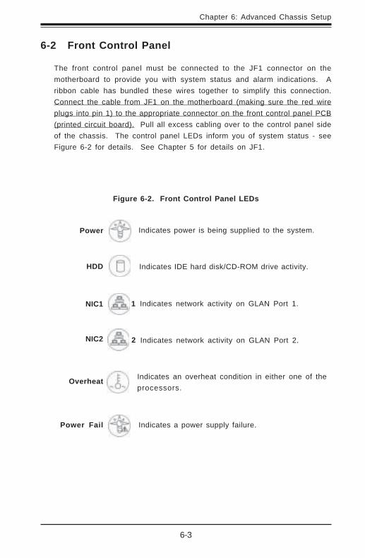
Chapter 6: Advanced Chassis Setup
6-3
6-2 Front Control Panel
The front control panel must be connected to the JF1 connector on themotherboard to provide you with system status and alarm indications. Aribbon cable has bundled these wires together to simplify this connection.Connect the cable from JF1 on the motherboard (making sure the red wireplugs into pin 1) to the appropriate connector on the front control panel PCB(printed circuit board). Pull all excess cabling over to the control panel sideof the chassis. The control panel LEDs inform you of system status - seeFigure 6-2 for details. See Chapter 5 for details on JF1.
Figure 6-2. Front Control Panel LEDs
Power
NIC1
HDD
Power Fail
Overheat
Indicates power is being supplied to the system.
Indicates network activity on GLAN Port 1.
Indicates IDE hard disk/CD-ROM drive activity.
Indicates a power supply failure.
Indicates an overheat condition in either one of theprocessors.
NIC2 Indicates network activity on GLAN Port 2.
1
2

6-4
SUPERWORKSTATION 7043L-8R Manual
6-3 System Fans
Two 9-cm chassis cooling fans located between the motherboard and thedrive bays provide cool air intake for the system. A heavy duty 12-cmexhaust fan at the rear of the chassis pulls the cooling air through thesystem and expels the hot air. The power supply has two fans; a primaryand a secondary.
Fan Failure
Under normal operation, both chassis fans, the exhaust fan and the primarypower supply fan run continuously. If the primary power supply fan fails,the power fail LED on the control panel will illuminate, an alarm will soundand the secondary power supply fan will activate. The reset button on theback of the power supply will disable the alarm. The system can operatewith only one power supply fan, but you should replace the power supplyas soon as possible. Both chassis cooling fans (not the exhaust fan) arehot-swappable and can be replaced without powering down the system.
Replacing System Fans
1. Identifying the failed fan:Inspect the back of the chassis to see if the 12-cm exhaust fan hasfailed. You must power down the system to replace this fan. To replacea failed chassis cooling fan, you must first remove the top/left chassiscover. Remove the two screws from the back lip of the top/left cover.Push in the release tab on the cover and push the cover toward the rearof the chassis until it stops (after moving about ½ inch). Then lift thecover up and off the chassis and see which fan has failed.
2. Removing a hot-plug fan housing:Depress the locking tab on a chassis cooling fan and pull the unit straightout by the handle. The fan wiring for these two fans has been designedto detach automatically. The 12-cm exhaust fan is also in a housing thatcan be removed from the chassis (not hot-swappable - see Figure 6-3).
3. Installing a new system fan:Replace the failed fan with an identical one (available from Supermicro).After the new fan has been installed, reassemble the fan housing andplug the housing back into its slot. You should hear it click into placewhen fully inserted. Check that the fan is working properly. Finish byreplacing the top/left side chassis panel.
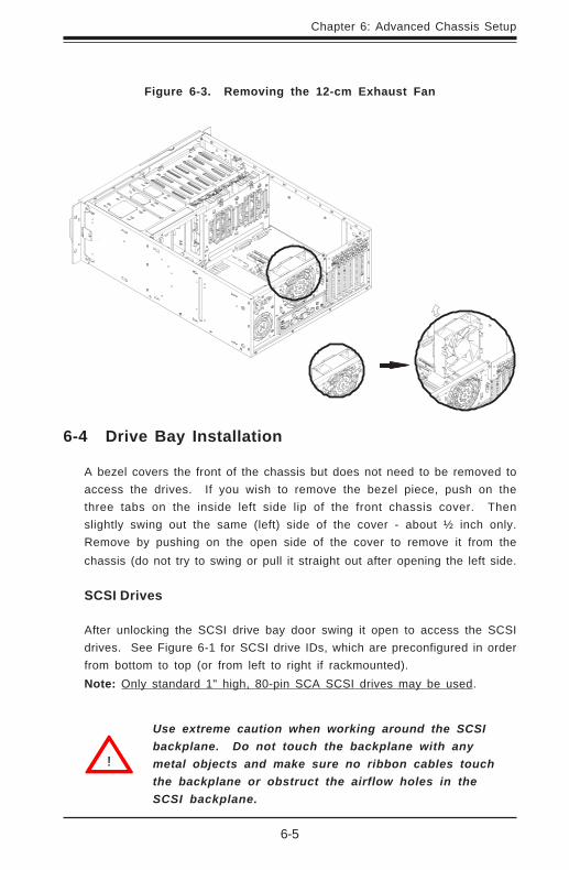
Chapter 6: Advanced Chassis Setup
6-5
Figure 6-3. Removing the 12-cm Exhaust Fan
6-4 Drive Bay Installation
A bezel covers the front of the chassis but does not need to be removed toaccess the drives. If you wish to remove the bezel piece, push on thethree tabs on the inside left side lip of the front chassis cover. Thenslightly swing out the same (left) side of the cover - about ½ inch only.Remove by pushing on the open side of the cover to remove it from thechassis (do not try to swing or pull it straight out after opening the left side.
SCSI Drives
After unlocking the SCSI drive bay door swing it open to access the SCSIdrives. See Figure 6-1 for SCSI drive IDs, which are preconfigured in orderfrom bottom to top (or from left to right if rackmounted).Note: Only standard 1" high, 80-pin SCA SCSI drives may be used.
Use extreme caution when working around the SCSIbackplane. Do not touch the backplane with anymetal objects and make sure no ribbon cables touchthe backplane or obstruct the airflow holes in theSCSI backplane.
!
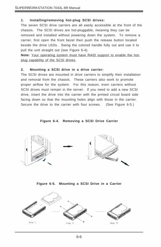
6-6
SUPERWORKSTATION 7043L-8R Manual
1. Installing/removing hot-plug SCSI drives:The seven SCSI drive carriers are all easily accessible at the front of thechassis. The SCSI drives are hot-pluggable, meaning they can beremoved and installed without powering down the system. To remove acarrier, first open the front bezel then push the release button locatedbeside the drive LEDs. Swing the colored handle fully out and use it topull the unit straight out (see Figure 6-4).Note: Your operating system must have RAID support to enable the hot-plug capability of the SCSI drives.
2. Mounting a SCSI drive in a drive carrier:The SCSI drives are mounted in drive carriers to simplify their installationand removal from the chassis. These carriers also work to promoteproper airflow for the system. For this reason, even carriers withoutSCSI drives must remain in the server. If you need to add a new SCSIdrive, insert the drive into the carrier with the printed circuit board sidefacing down so that the mounting holes align with those in the carrier.Secure the drive to the carrier with four screws. (See Figure 6-5.)
Figure 6-5. Mounting a SCSI Drive in a Carrier
Figure 6-4. Removing a SCSI Drive Carrier

Chapter 6: Advanced Chassis Setup
6-7
Always route SCSI power and ribbon cables so thatthey do not impede airflow or interfere with runningfans.
3. SCSI backplane:All seven SCSI drives plug into the SCSI backplane (p/n SCA742), whichprovides dual channel, Ultra320 operation. There are no jumpers on theSCSI backplane. Ribbon cables from JA1/JA2 on the motherboard shouldbe connected to the LVD1/LVD2 connectors on the SCSI backplane (SCSIchannels A/B). There are also two power connectors on the backplane -both should be connected. See Figure 6-6 for the locations of backplaneconnectors - the reverse side of the backplane has seven connectorsthat the SCSI drives plug into when inserted with a SCSI drive carrier.See Figure 6-1 for channel and drive number configuration. You cannotcascade the SCSI backplane.
Figure 6-6. SCA742 SCSI Backplane
Power ConnectorLVD1, 2
!
!Important: Regardless of how many SCSI hard drivesare installed, all seven SCSI drive carriers must remainin the drive bays to promote proper airflow.
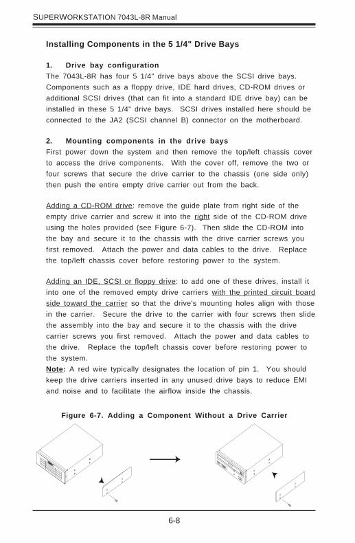
6-8
SUPERWORKSTATION 7043L-8R Manual
Installing Components in the 5 1/4" Drive Bays
1. Drive bay configurationThe 7043L-8R has four 5 1/4" drive bays above the SCSI drive bays.Components such as a floppy drive, IDE hard drives, CD-ROM drives oradditional SCSI drives (that can fit into a standard IDE drive bay) can beinstalled in these 5 1/4" drive bays. SCSI drives installed here should beconnected to the JA2 (SCSI channel B) connector on the motherboard.
2. Mounting components in the drive baysFirst power down the system and then remove the top/left chassis coverto access the drive components. With the cover off, remove the two orfour screws that secure the drive carrier to the chassis (one side only)then push the entire empty drive carrier out from the back.
Adding a CD-ROM drive: remove the guide plate from right side of theempty drive carrier and screw it into the right side of the CD-ROM driveusing the holes provided (see Figure 6-7). Then slide the CD-ROM intothe bay and secure it to the chassis with the drive carrier screws youfirst removed. Attach the power and data cables to the drive. Replacethe top/left chassis cover before restoring power to the system.
Adding an IDE, SCSI or floppy drive: to add one of these drives, install itinto one of the removed empty drive carriers with the printed circuit boardside toward the carrier so that the drive's mounting holes align with thosein the carrier. Secure the drive to the carrier with four screws then slidethe assembly into the bay and secure it to the chassis with the drivecarrier screws you first removed. Attach the power and data cables tothe drive. Replace the top/left chassis cover before restoring power tothe system.Note: A red wire typically designates the location of pin 1. You shouldkeep the drive carriers inserted in any unused drive bays to reduce EMIand noise and to facilitate the airflow inside the chassis.
Figure 6-7. Adding a Component Without a Drive Carrier

Chapter 6: Advanced Chassis Setup
6-9
6-5 Power Supply
The 7043L-8R has a triple redundant 600 watt redundant cooling powersupply that consists of three 300W power modules. All three modules areactive and share the load of the system (up to 600W max.). If any of thethree modules fail, the other two will continue to provide up to 600W ofpower and allow the system to continue running without interruption. Thepower supply modules have an auto-switching capability that enable themto automatically sense and operate at a 110 to 240V AC input. They arealso PFC (Power Factor Correction) compliant.
Power Supply Failure
If a power supply module fails, an audible alarm will activate to notify you ofa power failure. The PWR Fail LED and the LED on the back of the powersupply will also illuminate and remain on (until the failed unit has beenreplaced).
Replacing the Power Supply
1. Accessing the power supply:You do not need to power down the system to replace a power moduleon the 7043L-8R. Remove the left/top chassis cover to access thepower supply for removal.
2. Removing the power supply:First, unplug the power cord from the failed power supply module. Next,press the locking tab on the module and then pull the unit completely out.
3. Installing a new power supply module:Replace the failed unit with another unit having the exact same partnumber. Gently but firmly push the new unit all the way into the openbay. Secure it to the chassis using the locking tab. Finish by replacingthe chassis left/top cover and then restoring power to the system.

6-10
SUPERWORKSTATION 7043L-8R Manual
Notes
Chapter 7: AMIBIOS
7-1
Chapter 7AMIBIOS
7-1 Introduction
This chapter describes the AMIBIOS for the X5DL8-GG. The AMI ROM BIOSis stored in a Flash EEPROM and can be easily upgraded using a floppydisk-based program.
Note: Due to periodic changes to BIOS, some settings may have beenadded or deleted and might not yet be recorded in this manual. Refer to theManual Download area of our web site for any changes to BIOS that arenot reflected in this manual.
System BIOS
The BIOS is the Basic Input Output System used in all IBM® PC, XT™, AT®,and PS/2® compatible computers. The BIOS ROM stores the system param-eters, such as amount of memory, type of disk drives and video displays,etc. BIOS ROM requires very little power. When the computer is turned off,a back-up battery provides power to the BIOS ROM, enabling it to retain thesystem parameters. Each time the computer is powered-on, the computer isthen configured with the values stored in the BIOS ROM by the systemBIOS, which gains control when the computer is powered on.
How To Change the Configuration Data
The configuration data that determines the system parameters may bechanged by entering the BIOS Setup utility. This Setup utility can be ac-cessed by pressing <Del> at the appropriate time during system boot.
Starting the Setup Utility
Normally, the only visible POST (Power On Self Test) routine is the memorytest. As the memory is being tested, press the <Delete> key to enter themain menu of the BIOS Setup utility. From the main menu, you can accessthe other setup screens, such as the Chipset and Power menus. Section 4-3 gives detailed descriptions of each parameter setting in the Setup utility.
An AMIBIOS identification string is displayed at the left bottom corner of thescreen, below the copyright message.
7-2
SUPERSERVER 7043L-8R Manual
7-2 BIOS Features
• Supports Plug and Play V1.0A and DMI 2.3
• Supports Intel PCI (Peripheral Component Interconnect) (PME) local busspecification 2.2
• Supports Advanced Power Management (APM) specification v 1.1
• Supports ACPI
• Supports Flash ROM
AMIBIOS supports the LS120 drive made by Matsushita-Kotobuki ElectronicsIndustries Ltd. The LS120:
• Can be used as a boot device
• Is accessible as the next available floppy drive
AMIBIOS supports PC Health Monitoring chips. When a failure occurs in amonitored activity, AMIBIOS can sound an alarm and display a message.The PC Health Monitoring chips monitor:
• CPU temperature
• Chassis intrusion detector
• Five positive voltage inputs
• Four fan speed monitor inputs
7-3 Running Setup
*Optimal default settings are in bold text unless otherwise noted.
The BIOS setup options described in this section are selected by choosingthe appropriate text from the Standard Setup screen. All displayed text isdescribed in this section, although the screen display is often all you needto understand how to set the options (see on next page).

Chapter 7: AMIBIOS
7-3
Use the Up/Down arrow keys or the <Tab> key to move between the differentsettings in the above menu.
When the items "System Time", and "System Date" are highlighted, type in thecorrect time/date in the time field, and then press "Enter". The date must be enteredin MM/DD/YY format. The time is entered in HH:MM:SS format. The time is in also 24-hour format. For example, 5:30 a.m. appears as 05:30:00 and 5:30 p.m. as 17:30:00.
Press the <ESC> key to exit the Main Menu and use the Left/Right arrow keys toenter the the other categories of BIOS settings. The next section is described indetail to illustrate how to navigate through the menus.
Note: Items displayed in gray are preset and cannot be selected. Itemswith a blue arrow are commands, not options (i.e. Discard Changes).
7-4 Main BIOS Setup
Press the <Delete> key during the POST (Power On Self Test) to enter the Main Menuof the BIOS Setup Utility. All Main Setup options are described in this section. TheMain BIOS Setup screeen is displayed below.
BIOS SETUP UTILITY Main Advanced Chipset PCIPnP Power Boot Security Exit AMIBIOS Version: BIOS Build Date: BIOS ID: Processor Type: Processor Speed: System Memory: System Date System Time
07.00xx 11/16/02 5DL81119 Intel®Xeon® 2.4 GHz
8128 MB [12:31:57] [11/20/02]
↔ Select Screen ↑↓ Select Item +- Change Option F1 General Help F10 Save and Exit ESC Exit
V07.00 (C)Copyright 1985-2002, American Megatrends, Inc.
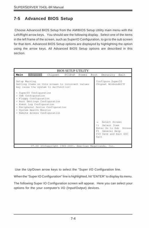
7-4
SUPERSERVER 7043L-8R Manual
Use the Up/Down arrow keys to select the "Super I/O Configuration line.
When the "Super IO Configuration" line is highlighted, hit "ENTER" to display its menu.
The following Super IO Configuration screen will appear. Here you can select youroptions for the your computer's I/O (Input/Output) devices.
7-5 Advanced BIOS Setup
Choose Advanced BIOS Setup from the AMIBIOS Setup Utility main menu with theLeft/Right arrow keys. You should see the following display. Select one of the itemsin the left frame of the screen, such as SuperIO Configuration, to go to the sub screenfor that item. Advanced BIOS Setup options are displayed by highlighting the optionusing the arrow keys. All Advanced BIOS Setup options are described in thissection.
BIOS SETUP UTILITY Main Advanced Chipset PCIPnP Power Boot Security Exit Setup Warning Setting items on this screen to incorrect values may cause the system to malfunction! > SuperIO Configuration > IDE Configuration > Floppy Configuration > Boot Settings Configuration > Event Log Configuration > Peripheral Device Configuration > System Health Monitor > Remote Access Configuration
Configure SuperIO Chipset Winbond627F ↔ Select Screen ↑↓ Select Item Enter Go to Sub Screen F1 General Help F10 Save and Exit ESC Exit
V7.00 (C)Copyright 1985-2001, American Megatrends, Inc.
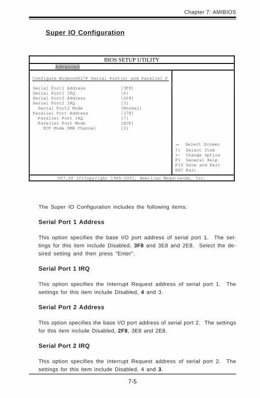
Chapter 7: AMIBIOS
7-5
Super IO Configuration
The Super IO Configuration includes the following items:
Serial Port 1 Address
This option specifies the base I/O port address of serial port 1. The set-tings for this item include Disabled, 3F8 and 3E8 and 2E8. Select the de-sired setting and then press "Enter".
Serial Port 1 IRQ
This option specifies the Interrupt Request address of serial port 1. Thesettings for this item include Disabled, 4 and 3.
Serial Port 2 Address
This option specifies the base I/O port address of serial port 2. The settingsfor this item include Disabled, 2F8, 3E8 and 2E8.
Serial Port 2 IRQ
This option specifies the Interrupt Request address of serial port 2. Thesettings for this item include Disabled, 4 and 3.
BIOS SETUP UTILITY Advanced Configure Winbond627F Serial Port(s) and Parallel P
Serial Port1 Address Serial Port1 IRQ Serial Port2 Address Serial Port2 IRQ Serial Port2 Mode Parallel Port Address Parallel Port IRQ Parallel Port Mode ECP Mode DMA Channel
[3F8] [4] [2F8] [3] [Normal] [378] [7] [ECP] [3]
↔ Select Screen ↑↓ Select Item +- Change Option F1 General Help F10 Save and Exit ESC Exit
V07.00 (C)Copyright 1985-2001, American Megatrends, Inc.

7-6
SUPERSERVER 7043L-8R Manual
Serial Port 2 Mode
Use this option to choose the Serial Port 2 Mode. The settings areNormal, Sharp-IR, SIR and consumer.
Parallel Port Address
This option specifies the I/O address used by the parallel port. The settingsfor this item include Disabled, 378, 278 and 3BC. Select your setting andthen press "Enter".
Parallel Port IRQ
This option allows the user to set the Parallel Port IRQ. The settingsfor this item include 5 and 7.
Parallel Port Mode
This option specifies the parallel port mode. The settings for this iteminclude Normal, Bi-directional, EPP and ECP.
ECP Mode DMA Channel
This option allows the user to set the setting for the ECPMode of the DMA Channel. The settings for this item include0, 1 and 3.
IDE Configuration
Onboard PCI IDE Controller
This option allows the user to enable or disable the integrated IDE Control-ler. The settings include Disabled, Primary, Second and Both. Select "Dis-abled" to disable the Integrated IDE Controller. Select "Primary" to enablethe Primary IDE ontroller only. Select "Secondary" to enable the SecondaryIDE Controller only. Select "Both" to enable both Primary and SecondaryIDE Controllers.

Chapter 7: AMIBIOS
7-7
Primary IDE Master
When entering "Setup", BIOS automatically detects the presence ofIDE devices. This displays the auto detection status of the IDE de-vices. You can also manually configure the IDE drives by providing thefollowing information:
This option allows the user to configure the IDE devices. When the desireditem is highlighted (selected), press "Enter" and the following screen will bedisplayed:
Type
This option sets the type of device that the AMIBIOS attemptsto boot from after AMIBIOS POST is completed. The settingsinclude Not installed, Auto, CDROM and ARMD. The "Auto"setting allows BIOS to automatically detect the presence ofthe IDE controller.
LBA/Large Mode
LBA (Logical Block Addressing) is a method of addressingdata on a disk drive. In LBA mode, the maximum drive capacity is 137 GB. The settings are Disabled and Auto. Select"Disabled" to disable LBA mode. Select "Auto" to enable LBAmode if your device supports it and is not already formattedwith the LBA mode.
Block (Multi-Sector Transfer) Mode
This option sets the block mode multi sector transfers optionThe settings include Disabled and Auto. Disabled: This option prevents the BIOS from using Multi-Sector Transfer onthe specified channel. The data to and from the device willoccur one sector at a time. Auto: This option allows theBIOS to auto detect device support for Multi-Sector Transfers on the specified channel. If supported, this option allows the BIOS to auto detect the number of sectors per blockfor transfer from the hard disk drive to memory. The datatransfer to and from the device will occur multiple sectors ata time (if the device supports it).

7-8
SUPERSERVER 7043L-8R Manual
PIO Mode
IDE PIO (Programmable I/O) mode programs timing cycles between theIDE drive and the programmable IDE controller. As the PIO mode in-creases, the cycle time decreases. The settings are: Auto, 0, 1, 2, 3and 4.
DMA Mode
This item allows the users to select the DMA mode. Thesettings are: Auto, SWDMA0, SWDMA1, SWDMA2,MWDMA0, MWDMA1, MWDM2, UWDMA0, UWDMA1,UWDMA2, UWDMA3 and UWDMA4. Select Auto to auto de-tect the DMA Mode. Select SWDMA0 through SWDMA2 toset single word DMA0 through DMA2. Select MWDMA0through MWDMA2 to set Multi-word DMA0 through DMA2.Select UDMA0 trhough UDMA4 to set Ultra DMA0 throughUltra DMA4.
S.M.A.R.T.
S.M.A.R.T stands for Self-Monitoring Analysis and ReportingTechnology, a feature that can help predict impending drivefailures. The settings are Auto, Disabled and Enabled.Select "Enabled" or "Disabled" to enable or disable theS.M.A.R.T. Select "Auto" to auto detect S.M.A.R.T.
32Bit Data Transfer
The settings are Auto, Disabled and Enabled. Select "En-abled" or "Disabled" to enable or disable the 32-bit DataTransfer function. Select "Auto" to auto detect the 32-bitData Transfer function.
ARMD Emulation Type
This option is used to select the ARMD emulation type used whenconfiguring an LS120, MO (Magneto-Optical), or Iomega Zip drive.The settings are Auto, Floppy and HardDisk. (ARMD stands forATA(PI) Removable Media Disk).
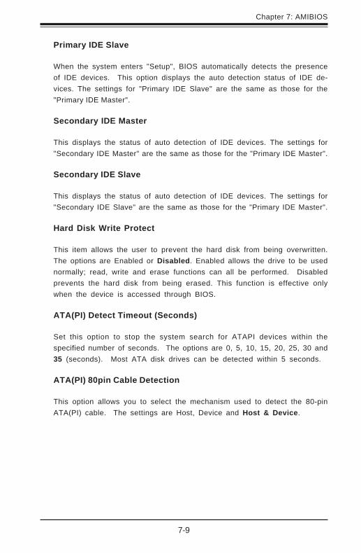
Chapter 7: AMIBIOS
7-9
Primary IDE Slave
When the system enters "Setup", BIOS automatically detects the presenceof IDE devices. This option displays the auto detection status of IDE de-vices. The settings for "Primary IDE Slave" are the same as those for the"Primary IDE Master".
Secondary IDE Master
This displays the status of auto detection of IDE devices. The settings for"Secondary IDE Master" are the same as those for the "Primary IDE Master".
Secondary IDE Slave
This displays the status of auto detection of IDE devices. The settings for"Secondary IDE Slave" are the same as those for the "Primary IDE Master".
Hard Disk Write Protect
This item allows the user to prevent the hard disk from being overwritten.The options are Enabled or Disabled. Enabled allows the drive to be usednormally; read, write and erase functions can all be performed. Disabledprevents the hard disk from being erased. This function is effective onlywhen the device is accessed through BIOS.
ATA(PI) Detect Timeout (Seconds)
Set this option to stop the system search for ATAPI devices within thespecified number of seconds. The options are 0, 5, 10, 15, 20, 25, 30 and35 (seconds). Most ATA disk drives can be detected within 5 seconds.
ATA(PI) 80pin Cable Detection
This option allows you to select the mechanism used to detect the 80-pinATA(PI) cable. The settings are Host, Device and Host & Device.

7-10
SUPERSERVER 7043L-8R Manual
Floppy Configuration
Floppy A
Use this option to specify which of floppy drive you have installed in the Adrive. The settings are Disabled, 360 KB 5 1/4", 1.2 MB 5 1/4", 720 KB 3 1/2", 1.44 MB 3 1/2" and 2.88 MB 3 1/2".
Floppy B
Use this option to specify which of floppy drive you have installed in the Bdrive. The settings are Disabled, 360 KB 5 1/4", 1.2 MB 5 1/4", 720 KB 3 1/2", 1.44 MB 3 1/2" and 2.88 MB 3 1/2".
Diskette Write Protect
This option allows you to prevent any writing to your floppy diskette. Thesettings are Disabled, 360 KB 5 1/4", 1.2 MB 5 1/4", 720 KB 3 1/2", 1.44MB 3 1/2" and 2.88 MB 3 1/2". The Enabled setting is effective only if thedevice is accessed through BIOS.
Floppy Drive Seek
Use this option to Enable or Disable the floppy seek routine on bootup.
Boot Settings Configuration
Quick Boot
This option allows the BIOS to skip certain tests that are normally perfomredon boot up. You can disable the option to speed up boot time. The settingsare Disabled and Enabled.
Quiet Boot
If Disabled, this option will cause the normal POST messages to be dis-played upon setup. When Enabled, the OEM logo is displayed instead of thePOST messages. The settings are Enabled and Disabled.
Add-On ROM Display Mode
Set this option to display add-on ROM (read-only memory) messages. Thesettings for this option are Force BIOS and Keep Current. Force BIOS
Chapter 7: AMIBIOS
7-11
BootUp Num Lock
This option is used to select the status of the Number Lock function on yourkeyboard on bootup. The settings are On and Off.
BootUp CPU Speed
This option is used set the CPU speed to either High or Low.
PS/2 Mouse Support
This option specifies whether a PS/2 Mouse will be supported. Settings areEnabled and Disabled.
Typematic Rate
Set this option to select the rate at which the computer repeats a key thatis held down. Settings are Fast and Slow. Fast: This sets the rate thecomputer repeats a key to over 20 times per second. Under normal opera-tions, this setting should not be changed. Slow: This sets the rate thecomputer repeats a key to under 8 times per second.
Primary Display
This option specifies the type of monitor display you have installed on thesystem. The settings are Absent, VGA/EGA, Color 40 x 25, Color 80 x 25and monochrome.
Parity Check
Use this option to either Enable or Disable the use of memory parity check-ing.
Boot to OS/2
This option can be used to boot the system to an OS/2 operating system.The settings are No and Yes.
allows the computer to force a third party BIOS to display during systemboot. Keep Current has the system display AMIBIOS information on bootup.
7-12
SUPERSERVER 7043L-8R Manual
Wait for F1 if Error
This settings for this option are Enabled and Disabled. Disabled: Thisprevents the AMIBIOS to wait on an error for user intervention. This settingshould be used if there is a known reason for a BIOS error to appear. Anexample would be a system administrator must remote boot the system.The computer system does not have a keyboard currently attached. If thissetting is set, the system will continue to bootup in to the operating system.If ‘F1’ is enabled, the system will wait until the BIOS setup is entered.Enabled: This option allows the system BIOS to wait for any error. If anerror is detected, pressing <F1> will enter Setup and the BIOS setting canbe adjusted to fix the problem. This normally happens when upgrading thehardware and not setting the BIOS to recognize it.
Hit "Delete" Message Display
This option tells the system to display or not display the "Hit Delete to EnterSetup" message. The settings are Enabled and Disabled.
Cache
This option is for enabling or disabling the internal CPU L1 cache. Settingsinclude Disabled, Write-Thru, Write-Back and Reserved. Disabled: Thisoption prevents the system from using the internal CPU L1 cache. Thissetting should be used to slow the computer system down or to trouble-shoot error messages. Write-Thru: This option allows the computer systemto use the internal CPU L1 cache as Write-Though cache. Write-Throughcache is slower than Write-Back cache. It performs write operations to theinternal L1 CPU cache and system memory simultaneously. Write-Back:This option allows the computer system to use the internal CPU L1 cache asWrite-Back cache. Write-Back cache is faster than Write-Through cache.Write-Back cache is a caching method in which modifications to data in thecache aren’t copied to the cache source until absolutely necessary. Write-back caching is available on all CPUs supported by this BIOS. With theseCPUs, write operations stored in the L1 cache aren’t copied to main memoryuntil absolutely necessary. This is the default setting.
System BIOS Cacheable
This option enables you to move the system BIOS to the memory cache toimprove performance. Settings are Enabled and Disabled.
Chapter 7: AMIBIOS
7-13
Event Log Configuration
Event Logging
This option Enables or Disables the logging of events. You can use thisscreen to select options for the Event Log Configuration Settings. You canaccess sub screens to view the event log and mark all events as read. Usethe up and down arrow keys to select an item, and the plus (+) and minus(-) keys to change the option setting. The settings are described on thefollowing pages. The screen is shown below.
ECC Event Logging
This option Enables or Disables the logging of ECC events. The eventslogged by AMIBIOS are post errors such as a bad BIOS, floppy errors, orhard drive errors.
Clear All Event Logs
This option can be used to tell the system to clear the event log on the nextboot up. The settings are No and Yes.
View Event Log
Highlighting this and pressing <Enter> will allow you to view the unreadevents from the event log area.
Mark All Events As Read
Highlighting [OK] and pressing <Enter> will mark all events in the log area ashaving been read. The settings are OK and Cancel.

7-14
SUPERSERVER 7043L-8R Manual
Peripheral Device Configuration
Power Lost Control
This option determines how the system will respond when power is reap-plied after a power loss condition. Choose Always On to automaticallystart up the system when power is reapplied. Always Off means you mustpush the main power button to restart the system after power is restored.
System Health Monitor
The BIOS continuously monitors the health of your system by measuringcertain voltage levels and temperatures.
CPU1 Current Temperature/CPU2 Current Temperature
This reading displays the real-time temperatures of CPU1 and CPU2.
System Current Temperature1/System Current Temperature2
This reading displays two real-time temperatures of the system.
Remote Access Configuration
This option allows the user to redirect the console (display) through theCOM port when enabled. This is useful when two computers are hookedup to a single monitor. When enabled, the user can toggle the display fromone system to the other using the <Tab> key. The function keys are dis-abled when this setting is enabled. The settings are "Serial ANSI" and"Disabled."

Chapter 7: AMIBIOS
7-15
7-6 Chipset Setup
Choose Chipset Setup from the AMIBIOS Setup Utility main menu. The screenis shown below. All Chipset Setup options are described following thescreen.
BIOS SETUP UTILITY Main Advanced Chipset PCIPnP Power Boot Security Exit Memory Timing Control [Auto] SDRAM CAS Latency [CAS Latency 2.5] MPS 1.4 Support [Enabled] Hyper-threading [Enabled] Auto DQS Setting Support [Disabled] DQS Selection [36] Watch Dog Timer [Disabled]
Options for MCH ↔ Select Screen ↑↓ Select Item Enter Go to Sub Screen F1 General Help F10 Save and Exit ESC Exit
V07.00 (C)Copyright 1985-2002, American Megatrends, Inc.
Memory Timing Control
Determines how the memory timing is controlled. Auto lets BIOS programthe memory timing from SPD data. Manual allows the user to select theappropriate memory timing.
SDRAM CAS Latency
This sets the CAS latency for system memory. The default setting is CASLatency 2.5.
MPS 1.4 Support
The settings for this option are Enabled and Disabled.
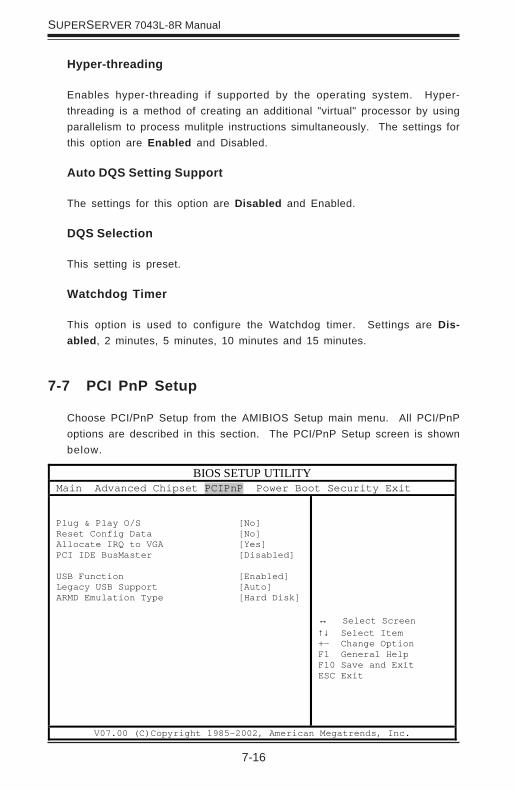
7-16
SUPERSERVER 7043L-8R Manual
7-7 PCI PnP Setup
Choose PCI/PnP Setup from the AMIBIOS Setup main menu. All PCI/PnPoptions are described in this section. The PCI/PnP Setup screen is shownbelow.
Hyper-threading
Enables hyper-threading if supported by the operating system. Hyper-threading is a method of creating an additional "virtual" processor by usingparallelism to process mulitple instructions simultaneously. The settings forthis option are Enabled and Disabled.
Auto DQS Setting Support
The settings for this option are Disabled and Enabled.
DQS Selection
This setting is preset.
Watchdog Timer
This option is used to configure the Watchdog timer. Settings are Dis-abled, 2 minutes, 5 minutes, 10 minutes and 15 minutes.
BIOS SETUP UTILITY Main Advanced Chipset PCIPnP Power Boot Security Exit Plug & Play O/S Reset Config Data Allocate IRQ to VGA PCI IDE BusMaster USB Function Legacy USB Support ARMD Emulation Type
[No] [No] [Yes] [Disabled] [Enabled] [Auto] [Hard Disk]
↔ Select Screen ↑↓ Select Item +- Change Option F1 General Help F10 Save and Exit ESC Exit
V07.00 (C)Copyright 1985-2002, American Megatrends, Inc.
Chapter 7: AMIBIOS
7-17
Plug & Play OS
This option specifies how Plug and Play devices will be configured. Thesettins are Yes and No. No lets BIOS configure all devices in the system.Yes lets the operating system (if supported) configure PnP devices notrequired for bootup.
Reset Configuration Data
Choosing the Yes setting will cause the PnP configuration data in the BIOSto be cleared on the next boot up. Choosing the No setting does not forcePnP data to be cleared on the next boot.
Allocate IRQ to VGA
This option lets you allocate an interrupt request (IRQ) to the PCI VGAadapter card (if used). The settings are Yes and No.
PCI IDE BusMaster
The settings for this option are Disabled and Enabled. Enable to specifythat the IDE controller on the PCI bus has bus mastering capabilities.
USB Function
The settings for this option are Disabled and Enabled. Disabled preventsthe use of the USB ports and Enabled allows the use of the USB ports.
Legacy USB Support
This option allows you to enable support for Legacy USB. The settings areAuto, Enabled and Disabled.
ARMD Emulation Type
This settings for this option are Hard Disk, Auto and Floppy.
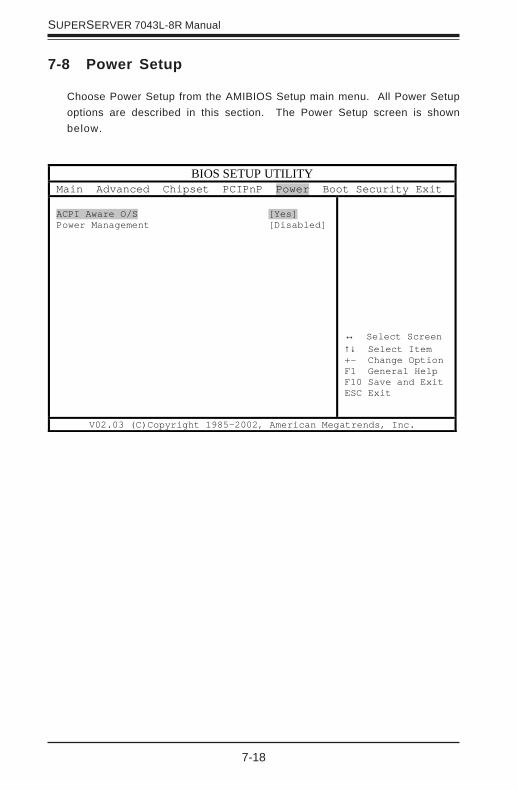
7-18
SUPERSERVER 7043L-8R Manual
7-8 Power Setup
Choose Power Setup from the AMIBIOS Setup main menu. All Power Setupoptions are described in this section. The Power Setup screen is shownbelow.
BIOS SETUP UTILITY Main Advanced Chipset PCIPnP Power Boot Security Exit ACPI Aware O/S Power Management
[Yes] [Disabled]
↔ Select Screen ↑↓ Select Item +- Change Option F1 General Help F10 Save and Exit ESC Exit
V02.03 (C)Copyright 1985-2002, American Megatrends, Inc.
Chapter 7: AMIBIOS
7-19
Power Button Mode
This option allows you to change the function of the chassis powerbutton. The settings are On/Off and Suspend. When set to Suspend,depressing the power button when the system is up will cause it toenter a suspend state.
Suspend Timeout
This option specifies the length of hard disk inactivity time that shouldexpire before entering the power conserving state. The settings areOff, 1, 2, 3, 4, 5, 6, 7, 8, 9 and 10 (minutes).
ACPI Aware O/S
This option allows the system to utilize Intel's ACPI (Advanced Configurationand Power Interface) specification. Settings are No and Yes. DOS®,Windows 3.x®, and Windows NT® are examples of non-ACPI aware oper-ating systems. Windows 95®, Windows 98®, Windows ME® and Windows2000® are examples of ACPI aware operating systems.
Power Management
When enabled, this option displays the following four options relating topower management. The settings are Disabled and Enabled.
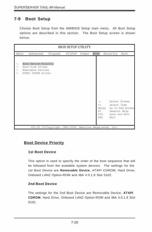
7-20
SUPERSERVER 7043L-8R Manual
7-9 Boot Setup
Choose Boot Setup from the AMIBIOS Setup main menu. All Boot Setupoptions are described in this section. The Boot Setup screen is shownbelow.
Boot Device Priority
1st Boot Device
This option is used to specify the order of the boot sequence that willbe followed from the available system devices. The settings for the1st Boot Device are Removable Device, ATAPI CDROM, Hard Drive,Onboard LAN2 Option-ROM and IBA 4.0.1.9 Slot 0102.
2nd Boot Device
The settings for the 2nd Boot Device are Removable Device, ATAPICDROM, Hard Drive, Onboard LAN2 Option-ROM and IBA 4.0.1.9 Slot0102.
BIOS SETUP UTILITY
Main Advanced Chipset PCIPnP Power Boot Security Exit > Boot Device Priority > Hard Disk Drives > Removable Devices > ATAPI CDROM Drives
↔ Select Screen ↑↓ Select Item Enter Go to Sub ScreenF1 General Help F10 Save and Exit ESC Exit
V02.03 (C)Copyright 1985-2000, American Megatrends, Inc.

Chapter 7: AMIBIOS
7-21
3rd Boot Device
The settings for the 3rd Boot Device are Removable Device, ATAPICDROM, Hard Drive, Onboard LAN2 Option-ROM and IBA 4.0.1.9 Slot0102.
4th Boot Device
The settings for the 4th Boot Device are Removable Device, ATAPICDROM, Hard Drive, Onboard LAN2 Option-ROM and IBA 4.0.1.9Slot 0102.
5th Boot Device
The settings for the 5th Boot Device are Removable Device, ATAPICDROM, Hard Drive, Onboard LAN2 Option-ROM and IBA 4.0.1.9 Slot0102.
Hard Disk Drives
Use this screen to view the boot sequency of hard drives that have beenauto-detected or entered manually on your system.
Removable Devices
Use this screen to view the boot sequency of the removeable devices thathave been auto-detected or entered manually on your system.
ATAPI CDROM Drives
Use this screen to view the boot sequency ofthe ATAPI CDROM drives thathave been auto-detected or entered manually on your system.
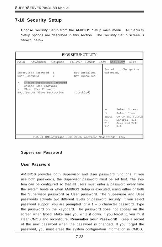
7-22
SUPERSERVER 7043L-8R Manual
7-10 Security Setup
Choose Security Setup from the AMIBIOS Setup main menu. All SecuritySetup options are described in this section. The Security Setup screen isshown below.
Supervisor Password
User Password
AMIBIOS provides both Supervisor and User password functions. If youuse both passwords, the Supervisor password must be set first. The sys-tem can be configured so that all users must enter a password every timethe system boots or when AMIBIOS Setup is executed, using either or boththe Supervisor password or User password. The Supervisor and Userpasswords activate two different levels of password security. If you selectpassword support, you are prompted for a 1 – 6 character password. Typethe password on the keyboard. The password does not appear on thescreen when typed. Make sure you write it down. If you forget it, you mustclear CMOS and reconfigure. Remember your Password! Keep a recordof the new password when the password is changed. If you forget thepassword, you must erase the system configuration information in CMOS.
BIOS SETUP UTILITY
Main Advanced Chipset PCIPnP Power Boot Security Exit Supervisor Password : Not Installed User Password : Not Installed > Change Supervisor Password > Change User Password > Clear User Password Boot Sector Virus Protection [Disabled]
Install or Change the password. ↔ Select Screen ↑↓ Select Item Enter Go to Sub ScreenF1 General Help F10 Save and Exit ESC Exit
V02.03 (C)Copyright 1985-2000, American Megatrends, Inc.

Chapter 7: AMIBIOS
7-23
Change Supervisor Password
This option allows you to change a supervisor password that was enteredpreviously.
Change User Password
This option allows you to change a user password that was entered previ-ously.
Clear User Password
Use this option to clear the user password so that it is not required to beentered when the system boots up.
Boot Sector Virus Protection
This option allows you to enable or disable a virus detection program toprotect the boot sector of your hard disk drive. The settings for this optionDisabled and Enabled. If Enabled, AMIBIOS will display a warning whenany program (or virus) issues a Disk Format command or attempts to writeto the boot sector of the hard disk drive.

7-24
SUPERSERVER 7043L-8R Manual
7-11 Exit Setup
Choose Exit Setup from the AMIBIOS Setup main menu. All Exit Setup op-tions are described in this section. The Exit Setup screen is shown below.
BIOS SETUP UTILITY
Main Advanced Chipset PCIPnP Power Boot Security Exit > Exit Saving Changes > Exit Discarding Changes > Load Optimal Defaults > Load Fail-Safe Defaults > Discard Changes
Exit system setup with saving the changes. ↔ Select Screen ↑↓ Select Item Enter Go to Sub ScreenF1 General Help F10 Save and Exit ESC Exit
V02.03 (C)Copyright 1985-2000, American Megatrends, Inc.
Exit Saving Changes
Highlighting this setting and then pressing <Enter> will save any changesyou made in the BIOS Setup program and then exit. Your system shouldthen continue with the boot up procedure.
Exit Discarding Changes
Highlighting this setting and then pressing <Enter> will ignore any changesyou made in the BIOS Setup program and then exit. Your system shouldthen continue with the boot up procedure.
Chapter 7: AMIBIOS
7-25
Load Optimal Defaults
Highlighting this setting and then pressing <Enter> provides the optimumperformance settings for all devices and system features.
Load Failsafe Defaults
Highlighting this setting and then pressing <Enter> provides the safest setof parameters for the system. Use them if the system is behaving errati-cally.
Discard Changes
Highlighting this setting and then pressing <Enter> will ignore any changesyou made in the BIOS Setup program but will not exit the BIOS Setup pro-gram.
7-26
SUPERSERVER 7043L-8R Manual
Notes

A-1
Appendix A: BIOS POST Messages
Appendix ABIOS POST Messages
During the Power-On Self-Test (POST), the BIOS will check for problems. If a problemis found, the BIOS will activate an alarm or display a message. The following is a listof such BIOS messages.
Failure Fixed DiskFixed disk is not working or not configured properly. Check to see if fixed disk isattached properly. Run Setup. Find out if the fixed-disk type is correctly identified.
Stuck keyStuck key on keyboard.
Keyboard errorKeyboard not working.
Keyboard Controller FailedKeyboard controller failed test. May require replacing keyboard controller.
Keyboard locked - Unlock key switchUnlock the system to proceed.
Monitor type does not match CMOS - Run SETUPMonitor type not correctly identified in Setup
Shadow Ram Failed at offset: nnnnShadow RAM failed at offset nnnn of the 64k block at which the errorwas detected.
System RAM Failed at offset: nnnnSystem RAM failed at offset nnnn of in the 64k block at which the errorwas detected.
Extended RAM Failed at offset: nnnn Extended memory notworking or not configured properly at offset nnnn.
System battery is dead - Replace and run SETUPThe CMOS clock battery indicator shows the battery is dead. Replace thebattery and run Setup to reconfigure the system.

A-2
SUPERWORKSTATION 7043L-8R Manual
System CMOS checksum bad - Default configuration usedSystem CMOS has been corrupted or modified incorrectly, perhaps by anapplication program that changes data stored in CMOS. The BIOS installed DefaultSetup Values. If you do not want these values, enter Setup and enter your ownvalues. If the error persists, check the system battery or contact your dealer.
System timer errorThe timer test failed. Requires repair of system board.
Real time clock errorReal-Time Clock fails BIOS hardware test. May require board repair.
Check date and time settingsBIOS found date or time out of range and reset the Real-Time Clock. May requiresetting legal date (1991-2099).
Previous boot incomplete - Default configuration usedPrevious POST did not complete successfully. POST loads default values andoffers to run Setup. If the failure was caused by incorrect values and they arenot corrected, the next boot will likely fail. On systems with control of waitstates, improper Setup settings can also terminate POST and cause this error onthe next boot. Run Setup and verify that the waitstate configuration is correct.This error is cleared the next time the system is booted.
Memory Size found by POST differed from CMOSMemory size found by POST differed from CMOS.
Diskette drive A errorDiskette drive B errorDrive A: or B: is present but fails the BIOS POST diskette tests. Check to see thatthe drive is defined with the proper diskette type in Setup and that the diskettedrive is attached correctly.
Incorrect Drive A type - run SETUPType of floppy drive A: not correctly identified in Setup.
Incorrect Drive B type - run SETUPType of floppy drive B: not correctly identified in Setup.
A-3
Appendix A: BIOS POST Messages
System cache error - Cache disabledRAM cache failed and BIOS disabled the cache. On older boards, check thecache jumpers. You may have to replace the cache. See your dealer. A disabledcache slows system performance considerably.
CPU ID:CPU socket number for Multi-Processor error.
EISA CMOS not writeableServerBIOS2 test error: Cannot write to EISA CMOS.
DMA Test FailedServerBIOS2 test error: Cannot write to extended DMA (Direct MemoryAccess) registers.
Software NMI FailedServerBIOS2 test error: Cannot generate software NMI (Non-MaskableInterrupt).
Fail-Safe Timer NMI FailedServerBIOS2 test error: Fail-Safe Timer takes too long.
device Address ConflictAddress conflict for specified device.
Allocation Error for: deviceRun ISA or EISA Configuration Utility to resolve resource conflict for thespecified device.
CD ROM DriveCD ROM Drive identified.
Entering SETUP ...Starting Setup program
Failing Bits: nnnnThe hex number nnnn is a map of the bits at the RAM address which failedthe memory test. Each 1 (one) in the map indicates a failed bit. See errors230, 231, or 232 above for offset address of the failure in System,Extended, or Shadow memory.
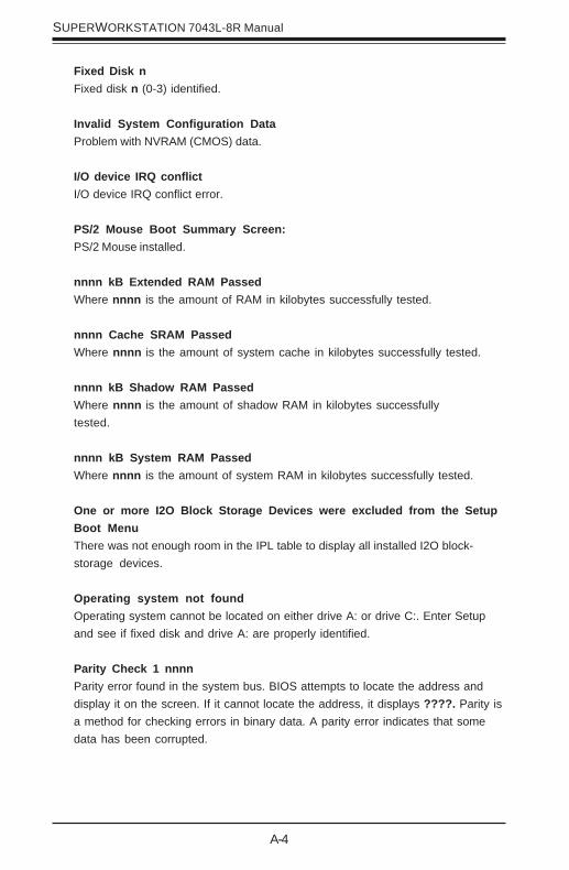
A-4
SUPERWORKSTATION 7043L-8R Manual
Fixed Disk nFixed disk n (0-3) identified.
Invalid System Configuration DataProblem with NVRAM (CMOS) data.
I/O device IRQ conflictI/O device IRQ conflict error.
PS/2 Mouse Boot Summary Screen:PS/2 Mouse installed.
nnnn kB Extended RAM PassedWhere nnnn is the amount of RAM in kilobytes successfully tested.
nnnn Cache SRAM PassedWhere nnnn is the amount of system cache in kilobytes successfully tested.
nnnn kB Shadow RAM PassedWhere nnnn is the amount of shadow RAM in kilobytes successfullytested.
nnnn kB System RAM PassedWhere nnnn is the amount of system RAM in kilobytes successfully tested.
One or more I2O Block Storage Devices were excluded from the SetupBoot MenuThere was not enough room in the IPL table to display all installed I2O block-storage devices.
Operating system not foundOperating system cannot be located on either drive A: or drive C:. Enter Setupand see if fixed disk and drive A: are properly identified.
Parity Check 1 nnnnParity error found in the system bus. BIOS attempts to locate the address anddisplay it on the screen. If it cannot locate the address, it displays ????. Parity isa method for checking errors in binary data. A parity error indicates that somedata has been corrupted.
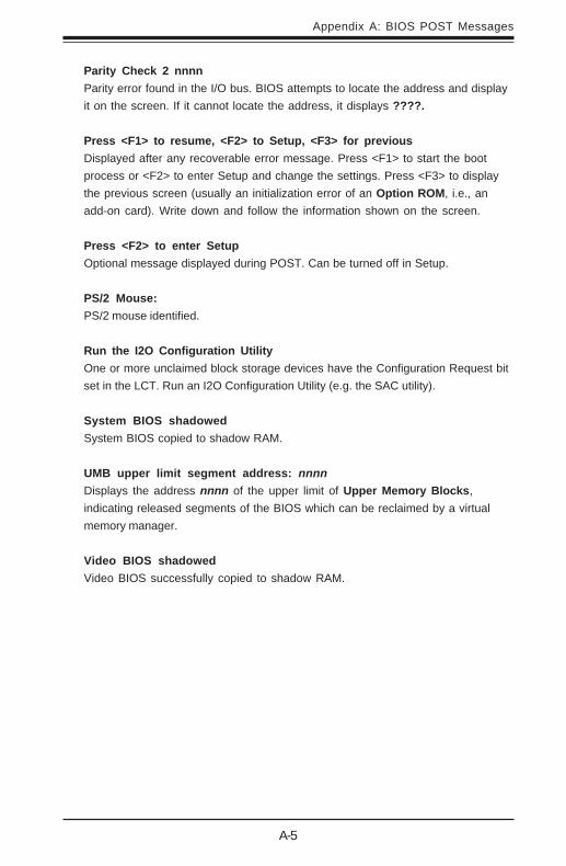
A-5
Appendix A: BIOS POST Messages
Parity Check 2 nnnnParity error found in the I/O bus. BIOS attempts to locate the address and displayit on the screen. If it cannot locate the address, it displays ????.
Press <F1> to resume, <F2> to Setup, <F3> for previousDisplayed after any recoverable error message. Press <F1> to start the bootprocess or <F2> to enter Setup and change the settings. Press <F3> to displaythe previous screen (usually an initialization error of an Option ROM, i.e., anadd-on card). Write down and follow the information shown on the screen.
Press <F2> to enter SetupOptional message displayed during POST. Can be turned off in Setup.
PS/2 Mouse:PS/2 mouse identified.
Run the I2O Configuration UtilityOne or more unclaimed block storage devices have the Configuration Request bitset in the LCT. Run an I2O Configuration Utility (e.g. the SAC utility).
System BIOS shadowedSystem BIOS copied to shadow RAM.
UMB upper limit segment address: nnnnDisplays the address nnnn of the upper limit of Upper Memory Blocks,indicating released segments of the BIOS which can be reclaimed by a virtualmemory manager.
Video BIOS shadowedVideo BIOS successfully copied to shadow RAM.

A-6
SUPERWORKSTATION 7043L-8R Manual
Notes

Appendix B: BIOS POST Codes
B-1
This section lists the POST (Power On Self Test) codes for the PhoenixBIOS. POSTcodes are divided into two categories: recoverable and terminal.
Recoverable POST Errors
When a recoverable type of error occurs during POST, the BIOS will displayan POST code that describes the problem. BIOS may also issue one of thefollowing beep codes:
1 long and two short beeps - video configuration error 1 continuous long beep - no memory detected
Terminal POST Errors
If a terminal type of error occurs, BIOS will shut down the system. Beforedoing so, BIOS will write the error to port 80h, attempt to initialize video andwrite the error in the top left corner of the screen.The following is a list of codes that may be written to port 80h.
Appendix BBIOS POST Codes
POST Code Description02h Verify Real Mode03h Disable Non-Maskable Interrupt (NMI)04h Get CPU type06h Initialize system hardware07h Disable shadow and execute code from the ROM.08h Initialize chipset with initial POST values09h Set IN POST flag0Ah Initialize CPU registers0Bh Enable CPU cache0Ch Initialize caches to initial POST values0Eh Initialize I/O component0Fh Initialize the local bus IDE10h Initialize Power Management11h Load alternate registers with initial POST values12h Restore CPU control word during warm boot13h Initialize PCI Bus Mastering devices14h Initialize keyboard controller16h 1-2-2-3 BIOS ROM checksum17h Initialize cache before memory Auto size

B-2
SUPERWORKSTATION 7043L-8R Manual
POST Code Description18h 8254 timer initialization1Ah 8237 DMA controller initialization1Ch Reset Programmable Interrupt Controller20h 1-3-1-1 Test DRAM refresh22h 1-3-1-3 Test 8742 Keyboard Controller24h Set ES segment register to 4 GB28h Auto size DRAM29h Initialize POST Memory Manager2Ah Clear 512 kB base RAM2Ch 1-3-4-1 RAM failure on address line xxxx*2Eh 1-3-4-3 RAM failure on data bits xxxx* of low byte of
memory bus2Fh Enable cache before system BIOS shadow32h Test CPU bus-clock frequency33h Initialize Phoenix Dispatch Manager36h Warm start shut down38h Shadow system BIOS ROM3Ah Auto size cache3Ch Advanced configuration of chipset registers3Dh Load alternate registers with CMOS values41h Initialize extended memory for RomPilot42h Initialize interrupt vectors45h POST device initialization46h 2-1-2-3 Check ROM copyright notice47h Initialize I20 support48h Check video configuration against CMOS49h Initialize PCI bus and devices4Ah Initialize all video adapters in system4Bh QuietBoot start (optional)4Ch Shadow video BIOS ROM4Eh Display BIOS copyright notice4Fh Initialize MultiBoot50h Display CPU type and speed51h Initialize EISA board52h Test keyboard54h Set key click if enabled55h Enable USB devices58h 2-2-3-1 Test for unexpected interrupts59h Initialize POST display service5Ah Display prompt “Press F2 to enter SETUP”5Bh Disable CPU cache

Appendix B: BIOS POST Codes
B-3
POST Code Description5Ch Test RAM between 512 and 640 kB60h Test extended memory62h Test extended memory address lines64h Jump to UserPatch166h Configure advanced cache registers67h Initialize Multi Processor APIC68h Enable external and CPU caches69h Setup System Management Mode (SMM) area6Ah Display external L2 cache size6Bh Load custom defaults (optional)6Ch Display shadow-area message6Eh Display possible high address for UMB recovery70h Display error messages72h Check for configuration errors76h Check for keyboard errors7Ch Set up hardware interrupt vectors7Dh Initialize Intelligent System Monitoring7Eh Initialize coprocessor if present80h Disable onboard Super I/O ports and IRQs81h Late POST device initialization82h Detect and install external RS232 ports83h Configure non-MCD IDE controllers84h Detect and install external parallel ports85h Initialize PC-compatible PnP ISA devices86h Re-initialize onboard I/O ports.87h Configure Motherboard Configurable Devices
(optional)88h Initialize BIOS Data Area89h Enable Non-Maskable Interrupts (NMIs)8Ah Initialize Extended BIOS Data Area8Bh Test and initialize PS/2 mouse8Ch Initialize floppy controller8Fh Determine number of ATA drives (optional)90h Initialize hard-disk controllers91h Initialize local-bus hard-disk controllers92h Jump to UserPatch293h Build MPTABLE for multi-processor boards95h Install CD ROM for boot96h Clear huge ES segment register97h Fix up Multi Processor table98h 1-2 Search for option ROMs. One long, two short
beeps on checksum failure
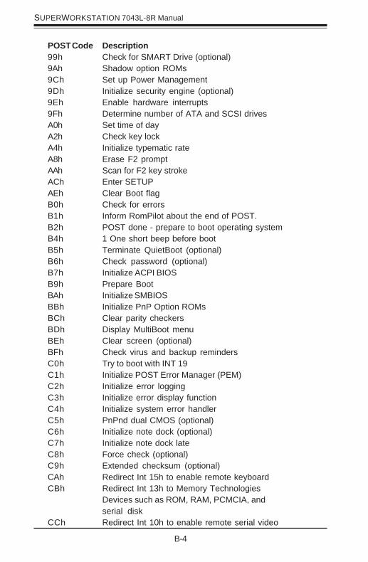
B-4
SUPERWORKSTATION 7043L-8R Manual
POST Code Description99h Check for SMART Drive (optional)9Ah Shadow option ROMs9Ch Set up Power Management9Dh Initialize security engine (optional)9Eh Enable hardware interrupts9Fh Determine number of ATA and SCSI drivesA0h Set time of dayA2h Check key lockA4h Initialize typematic rateA8h Erase F2 promptAAh Scan for F2 key strokeACh Enter SETUPAEh Clear Boot flagB0h Check for errorsB1h Inform RomPilot about the end of POST.B2h POST done - prepare to boot operating systemB4h 1 One short beep before bootB5h Terminate QuietBoot (optional)B6h Check password (optional)B7h Initialize ACPI BIOSB9h Prepare BootBAh Initialize SMBIOSBBh Initialize PnP Option ROMsBCh Clear parity checkersBDh Display MultiBoot menuBEh Clear screen (optional)BFh Check virus and backup remindersC0h Try to boot with INT 19C1h Initialize POST Error Manager (PEM)C2h Initialize error loggingC3h Initialize error display functionC4h Initialize system error handlerC5h PnPnd dual CMOS (optional)C6h Initialize note dock (optional)C7h Initialize note dock lateC8h Force check (optional)C9h Extended checksum (optional)CAh Redirect Int 15h to enable remote keyboardCBh Redirect Int 13h to Memory Technologies
Devices such as ROM, RAM, PCMCIA, andserial disk
CCh Redirect Int 10h to enable remote serial video

Appendix B: BIOS POST Codes
B-5
POST Code DescriptionCDh Re-map I/O and memory for PCMCIACEh Initialize digitizer and display messageD2h Unknown interrupt
The following are for boot block in Flash ROM
POST Code DescriptionE0h Initialize the chipsetE1h Initialize the bridgeE2h Initialize the CPUE3h Initialize system timerE4h Initialize system I/OE5h Check force recovery bootE6h Checksum BIOS ROME7h Go to BIOSE8h Set Huge SegmentE9h Initialize Multi ProcessorEAh Initialize OEM special codeEBh Initialize PIC and DMAECh Initialize Memory typeEDh Initialize Memory sizeEEh Shadow Boot BlockEFh System memory testF0h Initialize interrupt vectorsF1h Initialize Run Time ClockF2h Initialize videoF3h Initialize System Management ManagerF4h Output one beepF5h Clear Huge SegmentF6h Boot to Mini DOSF7h Boot to Full DOS
* If the BIOS detects error 2C, 2E, or 30 (base 512K RAM error), it displays an additionalword-bitmap (xxxx) indicating the address line or bits that failed. For example, “2C0002” means address line 1 (bit one set) has failed. “2E 1020" means data bits 12and 5 (bits 12 and 5 set) have failed in the lower 16 bits. The BIOS also sends thebitmap to the port-80 LED display. It first displays the checkpoint code, followed bya delay, the high-order byte, another delay, and then the loworder byte of the error.It repeats this sequence continuously.

B-6
SUPERWORKSTATION 7043L-8R Manual
Notes
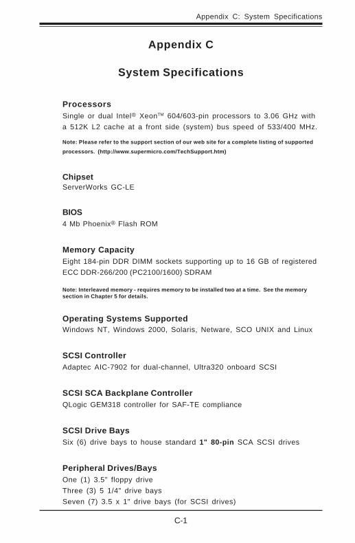
C-1
Appendix C: System Specifications
Appendix C
System Specifications
ProcessorsSingle or dual Intel® XeonTM 604/603-pin processors to 3.06 GHz witha 512K L2 cache at a front side (system) bus speed of 533/400 MHz.
Note: Please refer to the support section of our web site for a complete listing of supported
processors. (http://www.supermicro.com/TechSupport.htm)
ChipsetServerWorks GC-LE
BIOS4 Mb Phoenix® Flash ROM
Memory CapacityEight 184-pin DDR DIMM sockets supporting up to 16 GB of registeredECC DDR-266/200 (PC2100/1600) SDRAM
Note: Interleaved memory - requires memory to be installed two at a time. See the memorysection in Chapter 5 for details.
Operating Systems SupportedWindows NT, Windows 2000, Solaris, Netware, SCO UNIX and Linux
SCSI ControllerAdaptec AIC-7902 for dual-channel, Ultra320 onboard SCSI
SCSI SCA Backplane ControllerQLogic GEM318 controller for SAF-TE compliance
SCSI Drive BaysSix (6) drive bays to house standard 1" 80-pin SCA SCSI drives
Peripheral Drives/BaysOne (1) 3.5" floppy driveThree (3) 5 1/4" drive baysSeven (7) 3.5 x 1" drive bays (for SCSI drives)

C-2
SUPERWORKSTATION 7043L-8R Manual
Expansion SlotsChassis: Seven (7) I/O chassis slotsMotherboard: Total of six (6) PCI-X slots
MotherboardModel: X5DL8-GG (Extended ATX form factor)Dimensions: 12 x 13 in (305 x 330 mm)
ChassisModel: SC742S-600 (Tower/4U Rackmount)Dimensions: (WxHxD) 7 x 17.1 x 24.2 in. (178 x 434 x 615 mm)
WeightNet (Bare Bone): 52 lbs. (23.6 kg.)Gross (Bare Bone): 63 lbs. (28.6 kg.)
System CoolingTwo (2) 9-cm chassis cooling fans (hot-swappable)One (1) 12-cm exhaust fan
System Input RequirementsAC Input Voltage: 100-240V ACRated Input Current: 9A (115V) to 5A (230V)Rated Input Frequency: 50 to 60 Hz
Power SupplyRated Output Power: 600W (Model# SP602-TS, Part# PWS-044)Rated Output Voltages: +3.3V (36A), +5V (30A), +12V (24A), -12V(1A), +5Vsb (2A)
BTU Rating3240 BTUs/hr (for rated output power of 600W)
Operating EnvironmentOperating Temperature: 0 to +35 degrees CNon-operating Temperature: -35 to +60 degrees COperating Relative Humidity: 5-90%, non-condensingNon-operating Relative Humidity: 5-95%, non-condensing

C-3
Appendix C: System Specifications
Regulatory ComplianceElectromagnetic Emissions: FCC Class B, EN 55022 Class B, EN 61000-3-2 & -3-3, CISPR 22 Class B
Electromagnetic Immunity: EN 55024/CISPR 24, (EN 61000-4-2, EN61000-4-3, EN 61000-4-4, EN 61000-4-5, EN 61000-4-6, EN 61000-4-8,EN 61000-4-11)
Safety: EN 60950/IEC 60950-CompliantUL Listed (USA), CUL Listed (Canada), TUV Certified (Germany), CEMarking (Europe)

C-4
SUPERWORKSTATION 7043L-8R Manual
Notes