7010 gauss/tesla meter - f.w. bell · f.w. bell model 7010 gauss/tesla meter instruction manual...
TRANSCRIPT

7010 GAUSS/TESLA METER
Instruction Manual


MODEL 7010 GAUSS / TESLA METER
Instruction Manual
Manual UN-01-250 Item 359935 Rev. D, ECO 14211 All Rights Reserved.

F.W. BELL Model 7010 Gauss/Tesla Meter Instruction Manual
This symbol appears on the instrument and probe. It refers the operator to additional information contained in this instruction manual, also
identified by the same symbol.
NOTICE:
See Pages 4-1, 4-2, and 4-3 for SAFETY
instructions prior to first use !
See Page 2-4 for EMC Notes concerning I/O Cables and I/O
Filter Adapters

F.W. BELL Model 7010 Gauss/Tesla Meter Instruction Manual
i
Table of Contents Section – 1 Introduction Overview…………………………………………………………………………………….……….. 1-1General Description…………………………………………………………………………………. 1-3Applications…………………………………………………………………………………..…….… 1-8 Section – 2 Specifications Instrument…………………………………………………………………………………………….. 2-1Calibration Service…………………………………………………………………………………… 2-5Zero Flux Chamber………………………………………………………………………………….. 2-6 Section – 3 Probes Overview………………………………………………………………………………………...……. 3-1Probe Variations………………………………………………………………………………….…. 3-2Probe Memory……………………………………………………………………………………...… 3-3Probe Stem…………………………………………………………………………………..……….. 3-3Temperature Effects…………………………………………………………………………..…….. 3-3Fixturing………………………………………………………………………………………………. 3-3 Section – 4 Setup Safety………………………………………………………………………………………………… 4-1Line Voltage Settings / Fuse Panel………………………………………………………………… 4-3Adjusting the Handle………………………………………………………………………………… 4-4Probe Installation…………………………………………………………………………………….. 4-5Power Up……………………………………………………………………………………………… 4-6 Section – 5 User Interface Overview……………………………………………………………………………………………… 5-1Front Panel Key Pad………………………………………………………………………………… 5-2Menu System…………………………………………………………………………………………. 5-3Using the Mouse…………………………………………………………………………………….. 5-5Help System………………………………………………………………………………………….. 5-6System Menu……………………………………………………………………………………….. 5-6Setup Save-Load…………………………………………………………………………………….. 5-7Display Format……………………………………………………………………………………….. 5-9Setting the Date and Time…………………………………………………………………. 5-10
F.W. BELL Model 7010 Gauss/Tesla Meter Instruction Manual
ii
Section – 6 Flux Density Measurement Overview…………………………………………………………………………………………… 6-1Measurement Units and Selection……………………………………………………………… 6-2Present Flux Density Reading……………………………………………………..…….……… 6-3Measurement Mode Indicator…………………………………………………………………… 6-3Range Selection………………………………….……………………………………………… 6-4ac or dc Measurement Selection………………………………………………………………. 6-5ac Mode Operation……………………………………………………………………………… 6-5ac Mode Analog Filtering………………………………………………………………………… 6-7dc Mode Operation……………………………………………………………………………… 6-7Zeroing………..…………………………………………………………………………………….. 6-8Update Interval…………………………………………………………………………………… 6-10Hold Function………………………………………………………………………………………. 6-11Relative Mode…………………………………………………………………………………..… 6-13Analog Outputs……………………………………………………………………………………. 6-16Classifiers……………………………………………………………………………………….. 6-17Sources of Measurement Errors………………………………………………………………… 6-19 Section – 7 Remote Operation Introduction…………………………………………………………………………………………… 7-1IEEE 488 Functional Description…………………………………………………………………… 7-2RS-232 Functional Description……………………………………………………………………... 7-3Communications Setup……………………………………………………………………………. 7-5IEEE 488 General Bus Commands………………………………………………………………... 7-6Error Queue and Output Queue……………………………………………………………………. 7-7Status…………..……………………………………………………………………………………… 7-7Status Byte and Service Request………………………………………………………………….. 7-9Standard Event Register……………………………………………………………………………. 7-11Measurement Event Register………………………………………………………………….…. 7-12Operation Event Register…………………………………………………………………….…… 7-13Questionable Event Register……………..…………………………………………………….… 7-13IEEE 488.2 “Common” Command Syntax……………………………………………….……… 7-14IEEE 488.2 “Common” Commands……………………………………………………………… 7-15SCPI Command Syntax…………………………………………………………………………… 7-18SCPI Commands – General……………………………………………………………………… 7-19SCPI Commands – Error Queue Messages and Commands………………………………… 7-23SCPI Commands – System Information and Configuration Commands…………………… 7-23SCPI Commands – Status Commands………………………………………………………… 7-26SCPI Commands – Unit Commands………………………………………………………… 7-27
F.W. BELL Model 7010 Gauss/Tesla Meter Instruction Manual
iii
SCPI Commands – Range Commands…………………………………………………….…… 7-28SCPI Commands – Filter Commands…………………………………………………………… 7-29SCPI Commands – Averaging Commands…………………………………………………… 7-30SCPI Commands – Classifier (Limit) Commands……………………………………………… 7-30SCPI Commands – Zeroing Commands……………………………………………………… 7-32SCPI Commands – Relative Offset Commands……………………………………………… 7-32SCPI Commands – Analog Output Commands………………………………………………. 7-34SCPI Commands – Hold Commands…………….……………………………………………… 7-37SCPI Commands – Measurement Commands………………………………………………. 7-39Intermixing “Common” and SCPI Commands……………………………………………… 7-40Message Terminators…………………………………………………………………………… 7-41Example Using the Event, Enable, and Condition Registers………………………………… 7-42 Appendix A Understanding Flux Density………………………………………………… A-1 Warranty List of Tables Table 1-1 Model 7010 gauss/tesla meter List of Features……………………….…….. 1-2Table 1-2 Front Panel Description…………………………………………………..…….. 1-6Table 1-3 Rear Panel Description…………………………………………………..……... 1-7Table 2-1 Probe Ranges…………………………………………………………….…..….. 2-1Table 2-2 Accuracies (Instrument Only)……………………………………………..……. 2-2Table 3-1 Probe Maximum Field Levels and Resolutions…………………………..…... 3-2Table 5-1 Default Configuration Settings…………………………………….…….……... 5-8Table 5-2 Display Options…………………………………………………………..…….… 5-9Table 6-1 Available Units………………………………………………….……………..…. 6-2Table 6-2 Minimum Magnitudes for Rated ac Accuracy……………………..…….…… 6-6Table 6-3 Autofilter Switch Points………………………………………………..…...……. 6-7Table 6-4 Number of Samples for Update Interval Settings…………………………….. 6-10Table 7-1 RS-232 Available Settings………………………………………………………. 7-5Table 7-2 General Command Summary for IEEE 488…………………………………… 7-6Table 7-3 Common Command Summary……………………………………………...….. 7-15Table 7-4 SCPI Commands……………………………………………………...…………. 7-19Table 7-5 12 Hour to 24 Hour Conversion Table…………………………………………. 7-24Table 7-6 Operating Ranges with Various Probes…………………………………...…... 7-28

F.W. BELL Model 7010 Gauss/Tesla Meter Instruction Manual
iv
List of Illustrations Figure 1-1 Front Panel……………………………………………………………………….. 1-6Figure 1-2 Rear Panel…………………………………………………………………….….. 1-7Figure 1-3 Various Positions of Instrument………………………………………………… 1-8Figure 2-1 Frequency Response of Uncorrected Analog Outputs ……………..………. 2-3Figure 2-2 Digital I/O Connector……….……………………………………………………. 2-4Figure 2-3 Zero Flux Chamber………………………………………………………………. 2-6Figure 3-1 7000 Series Probe Ordering Guide…………………………………………….. 3-2Figure 3-2 Hall Probe Configurations………………………………………………….……. 3-4Figure 4-1 Probe Electrical Warning………………………………………………….…….. 4-2Figure 4-2 Fuse Panel……………………………………………………………………..…. 4-3Figure 4-3 Adjusting the Handle………………………………………………………….…. 4-4Figure 4-4 Installing and Removing Probes…………………………………………….….. 4-5Figure 4-5 Power Switch Positions………………………………………………………….. 4-6Figure 4-6 Boot Up Screen…………………………………………………………………... 4-7Figure 5-1 Front Panel Keys…………………………………………………………………. 5-2Figure 5-2 Menu Items……………………………………………………………………….. 5-3Figure 5-3 Using Selections…………………………………………………………………. 5-4Figure 5-4 Main Menu……………………………………………………………………….. 5-4Figure 6-1 Present Flux Density Reading………………………………………………….. 6-3Figure 6-2 Measurement Mode Indicator…………………………………………………... 6-3Figure 6-3 Frequency / Filter Indicator……………………………………………………… 6-5Figure 6-4 Indeterminate Frequency Indicator……………………………………………. 6-6Figure 6-5 Relative Value Indicator………………………………………………………… 6-14Figure 6-6 Example Circuit for Classifier Outputs………………………………………… 6-18Figure 6-7 Probe Output Versus Flux Angle………………………………………………. 6-19Figure 6-8 Probe Output Versus Distance…………………………………………………. 6-20Figure 6-9 Flux Density Variations in a Magnet…………………………………………… 6-20Figure 7-1 IEEE-488 Connector……………………………………………………………. 7-2Figure 7-2 RS-232 Connector………………………………………………………………. 7-4Figure 7-3 Condition, Event, and Enable Registers………………………………………. 7-8Figure 7-4 Status Byte and SRQ Enable Registers……………………………………… 7-9Figure 7-5 Standard Event Register……………………………………………………….. 7-11Figure 7-6 Measurement Event Register………………………………………………….. 7-12Figure 7-7 Operation Event Register……………………………………………………….. 7-13Figure 7-8 Questionable Event Register…………………………………………………… 7-13Figure A-1 Flux Lines of a Permanent Magnet…………………………………………….. A-1Figure A-2 Hall Effect Sensor……………………………………………………………...… A-2

F.W. BELL Model 7010 Gauss/Tesla Meter Instruction Manual
Section 1 - Introduction 1-1
Section 1 Introduction OVERVIEW The F.W. BELL model 7010 gauss/tesla meter incorporates the latest
developments in magnetic flux density measurement technology with a modern user interface. It features a large display for easy viewing, a comprehensive keypad for control of common functions, and an easy-to-use menu system. The model 7010 has high accuracy suitable for use in the laboratory, and enough features to be versatile in a manufacturing environment. Table 1-1 on the following page provides a list of features. A detailed description of the 7010’s functions and features is provided in the remaining sections.
F.W. BELL Model 7010 Gauss/Tesla Meter Instruction Manual
1-2 Section 1 - Introduction
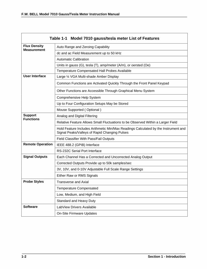
Table 1-1 Model 7010 gauss/tesla meter List of Features
Flux Density Measurement
Auto Range and Zeroing Capability
dc and ac Field Measurement up to 50 kHz
Automatic Calibration
Units in gauss (G), tesla (T), amp/meter (A/m), or oersted (Oe) Temperature Compensated Hall Probes Available
User Interface Large ¼ VGA Multi-shade Amber Display
Common Functions are Activated Quickly Through the Front Panel Keypad
Other Functions are Accessible Through Graphical Menu System
Comprehensive Help System
Up to Four Configuration Setups May be Stored
Mouse Supported ( Optional ) Support Functions
Analog and Digital Filtering
Relative Feature Allows Small Fluctuations to be Observed Within a Larger Field
Hold Feature Includes Arithmetic Min/Max Readings Calculated by the Instrument and Signal Peaks/Valleys of Rapid Changing Pulses
Field Classifier With Pass/Fail Outputs Remote Operation IEEE 488.2 (GPIB) Interface
RS-232C Serial Port Interface
Signal Outputs Each Channel Has a Corrected and Uncorrected Analog Output
Corrected Outputs Provide up to 50k samples/sec
3V, 10V, and 0-10V Adjustable Full Scale Range Settings
Either Raw or RMS Signals
Probe Styles Transverse and Axial
Temperature Compensated
Low, Medium, and High Field
Standard and Heavy Duty
Software LabView Drivers Available
On-Site Firmware Updates

F.W. BELL Model 7010 Gauss/Tesla Meter Instruction Manual
Section 1 - Introduction 1-3
GENERAL DESCRIPTION
The Model 7010 gauss/tesla meter utilizes a Hall effect probe to measure magnetic flux density in units of gauss (G), tesla (T), amp/meter (A/m), or oersted (Oe). Either steady-state (dc) or alternating (ac) fields may be measured. Fields as low as 10 µGauss (0.001 µT) or as high as 300k gauss (30 tesla), at frequencies up to 50 kHz, can be measured with extreme accuracy and 5-3/4 digit resolution. The instrument is calibrated and linearized from data stored within its probe. With a temperature compensated Hall probe, the instrument can compensate for errors due to temperature variations. User Interface The instrument features a ¼ VGA multi-shade amber graphics display. The display format and may be customized by the operator. The instrument automatically adjusts text sizes for the most convenient view for a given amount of information being displayed. Common functions are activated quickly through the front panel keypad. Each key has a back-light that is illuminated to indicate that it is active. Less commonly used functions are easily accessible through the menu system. The instrument also features a comprehensive help system. As an option, the 7000 series supports the use of a standard Microsoft® compatible serial mouse. Up to four configuration setups may be saved and recalled. Auto Range Four measurement ranges may be selected manually or the instrument can automatically select the best range based on the present flux density level being measured.

F.W. BELL Model 7010 Gauss/Tesla Meter Instruction Manual
1-4 Section 1 - Introduction
GENERAL DESCRIPTION (Continued)
Zero The “zero” function allows the user to remove undesirable readings from nearby magnetic fields (including earth’s) as well as to remove initial electrical offsets in the probe and instrument. A “zero flux chamber” is included as an accessory which shields the probe from external magnetic fields during this operation. Hold When the hold function is enabled the instrument will “hold” and display the highest and/or lowest flux density readings that have been measured. Hold features include capturing peaks and valleys of rapid changing pulses as well as arithmetically calculated max and min of slow changing signals. Relative Another feature, called “relative mode”, allows large flux readings to be suppressed so that small variations within the larger field can be observed directly. Update Interval The update interval of the reading may be adjusted. Shorter update intervals allow rapid fluctuations in flux density levels to be observed. Longer update intervals provide higher resolution and stability in the flux density reading. Analog Output A corrected and uncorrected analog output voltage signal is available from standard BNC connectors. The uncorrected output signal is representative of the magnetic flux density measured by the Hall probe. The corrected output signal is compensated for influences of temperature and frequency variations, as well as non-linearities inherent in the Hall probe and instrument. The corrected output is specified with a higher accuracy than the uncorrected output, with a bandwidth up to 200 Hz. The uncorrected output is less accurate, but has a bandwidth up to 50kHz.

F.W. BELL Model 7010 Gauss/Tesla Meter Instruction Manual
Section 1 - Introduction 1-5
GENERAL DESCRIPTION (Continued)
Standard full scale output ranges are 3V, 10V, 3VRMS, and 10VRMS. An adjustable full scale up to 9.9V or 9.9VRMS, in increments of 0.1V, is also available. These outputs may be connected to a voltmeter, oscilloscope, recorder, or external analog-to-digital converter. Analog Filters A low pass filter is available that may be set to pass frequencies only below 50kHz, 5kHz, or 500Hz. The instrument can automatically select the best filter setting based on the present flux density being measured. The filters affect both the displayed reading and the analog outputs. Field Classifier The “Classifier” function allows the user to define a lower and upper limit of flux density that can be used to quickly determine the status of a magnetic field. The instrument will indicate visually whether the field is below, within, or above the pre-defined limits. The same information is provided in the form of general purpose switch closures available at a standard 15 pin “D” type female connector. Remote Operation Remote operation is supported through a standard 9-pin “D” RS232 serial port connector or through an IEEE-488.2 (GPIB) instrumentation bus. The 7010 can be fully configured and flux density readings and other information can be acquired by a remote computer or PLC. The commands follow widely accepted protocols established by the IEEE-488.2 and SCPI-1999 standards. Accessories The instrument is shipped with a “zero flux chamber” used for shielding the probe from unwanted fields during zeroing. A sturdy carrying case is provided for the zero flux chamber, probes, and this manual.

F.W. BELL Model 7010 Gauss/Tesla Meter Instruction Manual
1-6 Section 1 - Introduction
GENERAL DESCRIPTION (Continued)
Front Panel The front panel consists of the ¼ VGA display, keypad, probe connectors, and power switch.
TABLE 1-2 FRONT PANEL DESCRIPTION
(1) Display 320 x 240 Pixel Electro-luminescent ¼ VGA display, Multi-Shade Amber Color
(2) Power Switch Push Button Type Power Switch
(3) Menu Key Used to Enter and Leave the Menu System
(4) Direction Keys Used to Navigate the Menu System (5) Enter Key Activates / De-activates Selections in the Menu System
(6) Range Key Selects Fixed Ranges or Autorange
(7) AC/DC Key Selects ac or dc Field Measurement
(8) Hold Key Activates / Deactivates the Hold Feature
(9) Reset Key Resets the Min/Max and Peak/Valley Detectors Used with the Hold Feature
(10) Relative Key Activates / De-activates the Relative Function
(11) Manual Adjust Adjusts the Relative or Zero Setting Up and Down
(12) Zero Key Starts the Zeroing Process
(13) Probe Connector 12 Pin Non-Magnetic Female Connector for Hall Effect Probes Figure 1-1 Front Panel
F.W. BELL Model 7010 Gauss/Tesla Meter Instruction Manual
Section 1 - Introduction 1-7
GENERAL DESCRIPTION (Continued)
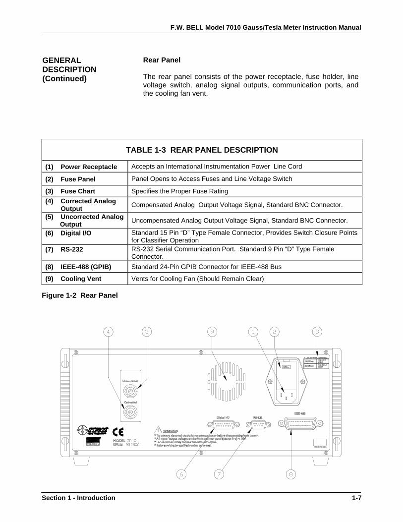
Rear Panel The rear panel consists of the power receptacle, fuse holder, line voltage switch, analog signal outputs, communication ports, and the cooling fan vent.
TABLE 1-3 REAR PANEL DESCRIPTION
(1) Power Receptacle Accepts an International Instrumentation Power Line Cord
(2) Fuse Panel Panel Opens to Access Fuses and Line Voltage Switch
(3) Fuse Chart Specifies the Proper Fuse Rating (4) Corrected Analog
Output Compensated Analog Output Voltage Signal, Standard BNC Connector.
(5) Uncorrected Analog Output Uncompensated Analog Output Voltage Signal, Standard BNC Connector.
(6) Digital I/O
Standard 15 Pin “D” Type Female Connector, Provides Switch Closure Points for Classifier Operation
(7) RS-232
RS-232 Serial Communication Port. Standard 9 Pin “D” Type Female Connector.
(8) IEEE-488 (GPIB) Standard 24-Pin GPIB Connector for IEEE-488 Bus
(9) Cooling Vent Vents for Cooling Fan (Should Remain Clear) Figure 1-2 Rear Panel
F.W. BELL Model 7010 Gauss/Tesla Meter Instruction Manual
1-8 Section 1 - Introduction
Raised Lowered Carrying
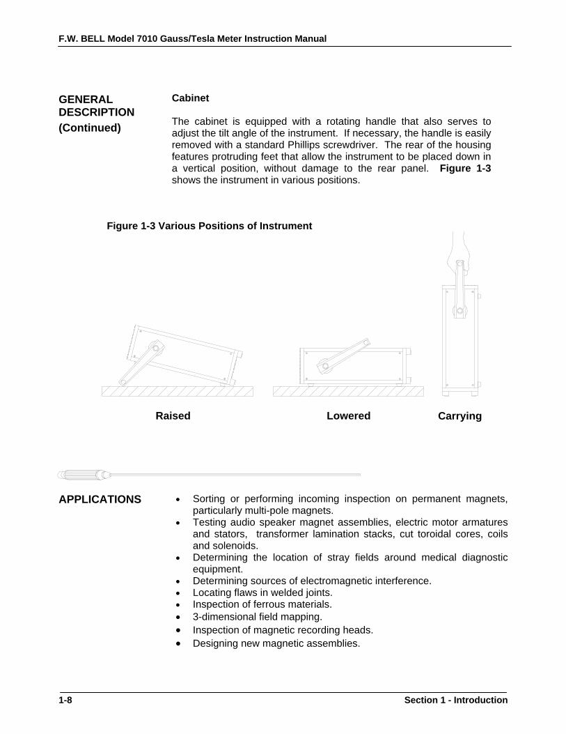
GENERAL DESCRIPTION (Continued)
Cabinet The cabinet is equipped with a rotating handle that also serves to adjust the tilt angle of the instrument. If necessary, the handle is easily removed with a standard Phillips screwdriver. The rear of the housing features protruding feet that allow the instrument to be placed down in a vertical position, without damage to the rear panel. Figure 1-3 shows the instrument in various positions.
Figure 1-3 Various Positions of Instrument APPLICATIONS • Sorting or performing incoming inspection on permanent magnets,
particularly multi-pole magnets. • Testing audio speaker magnet assemblies, electric motor armatures
and stators, transformer lamination stacks, cut toroidal cores, coils and solenoids.
• Determining the location of stray fields around medical diagnostic equipment.
• Determining sources of electromagnetic interference. • Locating flaws in welded joints. • Inspection of ferrous materials. • 3-dimensional field mapping. • Inspection of magnetic recording heads. • Designing new magnetic assemblies.

F.W. BELL Model 7010 Gauss/Tesla Meter Instruction Manual
Section 2 - Specifications 2-1
Section 2 Specifications INSTRUMENT Full-scale ranges are shown in the Tables 2-1a – 2-1c below; listed by probe type. In all cases, the resolution is 1 part in 300,000.
Table 2-1a: Ranges for Low Field Probe:
gauss (G) tesla (T) oersted (Oe) ampere-turn/meter (A/m) 300.000 mG 30.0000 µT 300.000 mOe 23.8732 A/m 3.00000 G 300.000 µT 3.00000 Oe 238.732 A/m
Note: Low Field probe cannot be used for measurements above 2 Gauss.
Table 2-1b: Ranges for Mid Field Probe:
gauss (G) tesla (T) oersted (Oe) ampere-turn/meter (A/m) 30.0000 G 3.00000 mT 30.0000 Oe 2.38732 kA/m 300.000 G 30.0000 mT 300.000 Oe 23.8732 kA/m 3.00000 kG 300.000 mT 3.00000 kOe 238.732 kA/m 30.0000 kG 3.00000 T 30.0000 kOe 2.38732 MA/m
Table 2-1c: Ranges for High Field Probe:
gauss (G) tesla (T) oersted (Oe) ampere-turn/meter (A/m) 300.000 G 30.0000 mT 300.000 Oe 23.8732 kA/m 3.00000 kG 300.000 mT 3.00000 kOe 238.732 kA/m 30.0000 kG 3.00000 T 30.0000 kOe 2.38732 MA/m 300.000 kG 30.0000 T 300.000 kOe 23.8732 MA/m

F.W. BELL Model 7010 Gauss/Tesla Meter Instruction Manual
2-2 Section 2 - Specifications
Table 2-2 Accuracies @23°C ( Instrument Only *)
Display and Digital Outputs (min speed)
Corrected Analog Output and Digital Outputs (max speed)
Uncorrected Analog Output
dc accuracy ±0.05% of reading and ±0.01% of range
±0.15% of 3V or 10V ranges
3V range: 0.25% of reading ±40mV 10V range: 0.25% of reading±120mV
ac accuracy In dc mode N/A 2% of range
dc to 100 hz 2% of range dc to 100Hz
ac accuracy in ac mode
2.0% of reading ± 0.15% of range (20 Hz to 50 kHz)
2.0% of 3V or 10V ranges (ac 20 to 500 Hz) (ac rms (dc) 20Hz-50kHz)
See Figure 2-1 for Graph (Typical) ac and ac rms (dc) output
ac peak accuracy 5.00% of Reading N/A N/A *Probes Errors Not Included Min / Max Hold Acquisition Time:
dc Mode: 200mS ac Mode: 200mS
Peak / Valley Hold Acquisition Time: dc Mode: 2ms ac Mode: 200µs
Temperature Coefficient: 0.02% of reading ±1 count/degree celsius
Update Rate: Display: 5/s (max) IEEE Output: 100/s (max) RS-232 Output: 100/s (max)
Temperature Range:
Operating: 0 to 50 degrees celsius Storage: -20 to 60 degrees celsius
Humidity Range: 0 to 35 degrees celsius 80% RH
Corrected Analog Output Noise (3V output range with 500 Hz filter):
All ranges: 2mV rms (35mV p-p)
Un-Corrected Analog Output Noise (3V output range with 500 Hz filter):
300G, 3kG, 30kG ranges: 50µV rms (10mV p-p) 30G range: 2mV rms (20mV p-p)
Analog Output Impedance: <100 Ohms Analog Output Connector: Standard BNC Analog Output Scaling: dc Mode: 3V or 10V standard ± 0.1V to ± 9.9V adjustable, with increments of 0.1 V
ac Mode: 3Vrms or 10Vrms standard ± 0.1Vrms to ± 9.9Vrms adjustable, with increments of 0.1 Vrms Front Panel Display:
Type: ¼ VGA 320 x 240 pixels graphic Electro- luminescent display with 4 shades of amber.
Dimensions: 4.7 W x 3.5 H inches 119 W x 89 H millimeters Power: Volts: 100/120 220/240 Frequency: 50-60 Hz or 50-60 Hz Current: 1.0 A (max) 0.5 A (max) Size:
16.3 W x 5.2 H x 13.5 D inches 414 W x 132 H x 343 D millimeters
Weight:
Net: 19.4 lbs. / 8.8 kg Shipping: 25.8 lbs. / 11.6 kg
Warm-up Time to Rated Accuracy: 60 Minutes

F.W. BELL Model 7010 Gauss/Tesla Meter Instruction Manual
Section 2 - Specifications 2-3
Figure 2-1 Frequency Response of Uncorrected Analog Outputs (Typical) No Probe (Instrument Only)
-35.00
-30.00
-25.00
-20.00
-15.00
-10.00
-5.00
0.00
5.00
1 10 100 1000 10000 100000
FREQUENCY (Hz)
PER
CEN
T O
F R
EAD
ING
ER
RO
R

F.W. BELL Model 7010 Gauss/Tesla Meter Instruction Manual
2-4 Section 2 - Specifications
Communications EMC application note Use only high quality, double shielded cables for the RS-232, IEEE-488 and Digital I/O connections. Keep the length of the cables less than 3 meters. Cables greater than 3 meters with insufficient EMI shielding can cause excessive emissions or may be susceptible to external interference. Adapters specified below for the RS-232 and digital I/O connectors must be used prior to connecting the RS 232 and digital I/O cables. Connection Description Insertion Loss Spectrum Control Part # RS-232 830pF Capacitive Type Filter,
“D” Type 9 Pin Male to Female 22dB @ 100MHz, 39dB @ 1GHz 56-705-008 , 830 pF
Digital I/O 1000pF Capacitive Type Filter, “D” Type 15 Pin Male to Female
20dB @ 100MHz, 40dB @ 1GHz 56-715-002, 1000 pF
Serial
Format: RS-232C Connector type: 9-pin “D” female Cable length: 3 m (9.8 ft.) maximum Receive input resistance: 3 kΩ minimum Receive voltage limit: ± 30 V maximum Transmit output voltage: ± 5 V min, ± 8 V typical Baud rate: 300, 600, 1200, 2400, 4800, 9600, 19200, 38400 Stop bits: 1, 2 Character length: 7,8 Parity: None, Odd, Even Handshaking None, Hardware, Software Standards supported: IEEE-1987.2, SCPI-1999
IEEE 488.2 (GPIB)
Format: IEEE 488.2 Standards supported: IEEE-1987.2, SCPI-1999
Digital I/O Signal Type: Relay Closure Connector: 15-Pin “D” Female Switching Voltage: 100 V dc or ac Peak MAX Switching Current: 0.25 A dc or ac Peak MAX Operating Time, Including Bounce: 2 mS MAX Classifier Connections
Low 3,11 High 4,12
Note: Do not connect to pins 7, 8, 15 Pin “D” and 15; factory use only! Figure 2-2 Digital I/O Connector

F.W. BELL Model 7010 Gauss/Tesla Meter Instruction Manual
Section 2 - Specifications 2-5
Regulatory Information: Compliance was demonstrated to the following specifications as listed in the official Journal of the European Communities: EN 50082-1:1997 Generic Immunity EN 61000-4-2 Electrostatic Discharge (ESD) Immunity EN 61000-4-3 and Radiated Electromagnetic Field (RF) Immunity EVN 50204 EN-61000-4-4 Electrical Fast Transient/Burst (EFT) Immunity EN-61000-4-5 Electrical Surge Immunity EN-61000-4-6 Conducted RF Disturbance Immunity EN-61000-4-8 Power Frequency Magnetic Field Immunity EN-61000-4-11 Voltage Dips and Voltage Interruptions Immunity EN 50081-1:1992 Generic Emissions EN 55022 Class B and Radiated and Conducted Emissions EN 55014
EN61010-1: 1993 and Safety EN61010-1 A2:1995 Safety Requirements for Electrical Equipment for Measurement, Control, and Laboratory use. CALIBRATION SERVICE
The instrument is calibrated at the factory prior to shipment. To maintain rated accuracy, it is recommended that the instrument be re-calibrated every 12 months. Answers to any questions concerning the calibration of this instrument may be obtained by contacting OECO, LLC at the address below: OECO, LLC 4607 SE International Way Milwaukie, OR 97222 Phone: 503-659-5999

F.W. BELL Model 7010 Gauss/Tesla Meter Instruction Manual
2-6 Section 2 - Specifications
ZERO FLUX CHAMBER Model Number: YA-111 Cavity Dimensions: Length: 50.8 mm (2”) Diameter: 8.7 mm (0.343”) Attenuation: 80 dB to 30 mT (300 G) Purpose: Figure 2- 3 To shield the probe from external magnetic fields during the ZERO or RELATIVE operations.
Zero Flux Chamber

F.W. BELL Model 7010 Gauss/Tesla Meter Instruction Manual
Section 3 - Probes 3-1
Section 3 Probes OVERVIEW F.W. Bell’s 7000 series gauss/tesla meter probes are designed to meet
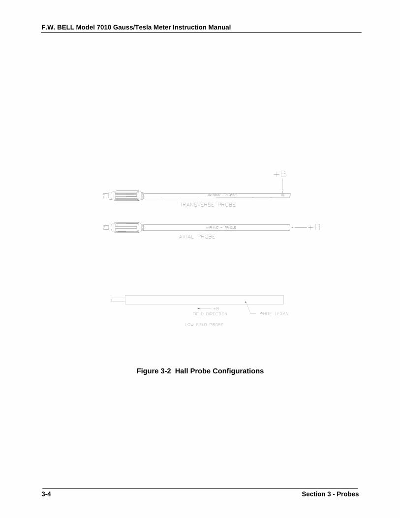
the electrical and mechanical requirements of virtually any application. Models are available for transverse, axial, and very low field measurements. The probe style is dependent upon the measurement environment. The standard fiberglass stem is recommended for laboratory or light handling environments, while the heavy duty aluminum stem is recommended for harsher environments. The probe’s length, outside diameter (axial probes) or thickness and width (transverse probes) are important if there are physical constraints where the probe will be used. In “transverse” probes the Hall generator is mounted in a thin, flat stem whereas in “axial” probes the Hall generator is mounted in a cylindrical stem. The primary difference is the axis of measurement, as shown by “+B” in Figure 3-2. Generally transverse probes are used to make measurements between two magnetic poles such as those in audio speakers, electric motors and imaging machines. Axial probes are often used to measure the magnetic field along the axis of a coil or solenoid. Either probe can be used where there are few physical space limitations, such as in geomagnetic or electromagnetic interference surveys. The low field probe is designed for high sensitivity, volumetric measurement such as mapping variations in the earth’s magnetic field or detecting the presence of ferrous objects.
Handle Hall probes with care. Do not bend the stem or apply pressure to the probe tip as damage may result.

F.W. BELL Model 7010 Gauss/Tesla Meter Instruction Manual
3-2 Section 3 - Probes
PROBE VARIATIONS
A wide variety of probes are available for use with the 7010 gauss/tesla meters. The types include heavy-duty transverse and axial, standard transverse and axial, standard transverse with exposed element, flexible transverse and axial with exposed element and low field probes. All of these probes are available with or without temperature compensation. All probes are available with 5, 15 or 30 foot (1.5, 4.5 and 9 meter) cable lengths and most are available with various stem lengths. Table 3-1 lists the maximum field measurement capabilities and resolutions.
Table 3-1 Probe Maximum Field Levels and Resolutions Probe Type Maximum Field Resolution
Low Field 2 G (200 µT) 1 µG (0.1 nT)Medium Field 30 kG (3 T) 0.1 mG (0.01 µT)
High Field 300 kG (30 T) 1 mG (0.1 µT) Figure 3-1 serves as an ordering guide for F.W. BELL 7000 series probes.
Full electrical and mechanical specifications of all probes are available on request.
Figure 3-1 7000 Series Probe Ordering Guide Note: Probes are not available in all part number combinations.

F.W. BELL Model 7010 Gauss/Tesla Meter Instruction Manual
Section 3 - Probes 3-3
PROBE MEMORY
The connector of each probe contains a memory device which stores registration information (model number, serial number, date calibrated, etc.) as well as performance information for Hall generator sensitivity, linearity, frequency response and temperature response. Each probe is physically identified with model number, serial number and a maximum voltage rating of “30VRMS / 60Vdc MAX” on a durable polyester label wrapped around the cable jacket.
PROBE STEM
All probes except the low field probe are supplied with a rigid stem cover to protect the probe when not in use. It is strongly recommended to use the stem protector when storing the probe or when the probe will not be used for any length of time. If a probe stem becomes damaged it can not be repaired.
TEMPERATURE EFFECTS
All Hall probes have an initial electrical offset that will affect the accuracy of static (dc) field measurements. This offset should be canceled using the instrument’s “zero” function. However, the probe’s offset and sensitivity will change with temperature. Using temperature-compensated probes will minimize these effects. There can be substantial errors in uncompensated probes. A typical probe’s dc offset can change by ± 0.1 G / °C (±10 µT / °C). It is best to allow the probe’s temperature to stabilize before performing a “zeroing” operation. Zeroing is discussed in Section 6 – Flux Density Measurement. The probe’s sensitivity will decrease as temperature increases. Probes are calibrated at ambient temperature (23 °C). A typical probe may change by –0.05% / °C. For instance a reading of 200 mT at 23°C may drop to 197 mT at 50°C.
FIXTURING In some applications it may be necessary to install a probe into a holding
fixture to maintain a constant probe position. If this becomes necessary, do not clamp onto the probe stem as this will most likely damage the probe. Rather, clamp onto the aluminum probe body.
F.W. BELL Model 7010 Gauss/Tesla Meter Instruction Manual
3-4 Section 3 - Probes
Figure 3-2 Hall Probe Configurations

F.W. BELL Model 7010 Gauss/Tesla Meter Instruction Manual
Section 4 - Setup 4-1
Section 4 Setup SAFETY INSTRUCTIONS GENERAL:
For safe and correct use of this instrument it is necessary that both operating and servicing personnel follow generally accepted safety procedures plus the safety cautions and warnings specified. If it is determined that safety protection has been impaired, the instrument must be made inoperative and be secured against any unintended operation. For example, safety may be impaired if the instrument fails to perform or shows visible damage.
CAUTION: All input and output voltages, except line (mains), are less than 20V.
WARNING: The opening of covers or removal of parts might expose live parts and accessible terminals which can be dangerous.
WARNING: The display generates voltages capable of causing personal injury (high voltage pulses up to 195 Vac ). Do not touch the display electronics during operation.
WARNING: Any interruption of protective earth conductors or disconnection of the protective earth terminals inside or outside of the instrument can create a dangerous condition.
CAUTION: For continued protection replace the fuse with the same type (IEC 127 type T).

F.W. BELL Model 7010 Gauss/Tesla Meter Instruction Manual
4-2 Section 4 - Setup
SAFETY INSTRUCTIONS (Continued) WARNING:
The Hall probe is a non-contact measuring device. The probe is not to contact a surface which exceeds a voltage of 30Vrms (42.4V peak) or 60V d.c.
Figure 4-1 Probe Electrical Warning
CAUTION: This instrument may contain ferrous components which will exhibit attraction to a magnetic field. Care should be utilized when operating the instrument near large magnetic fields, as pull-in may occur. Extension cables are available to increase the probe cable length, so that the instrument can remain in a safe position with respect to the field being measured with the probe.
F.W. BELL Model 7010 Gauss/Tesla Meter Instruction Manual
Section 4 - Setup 4-3
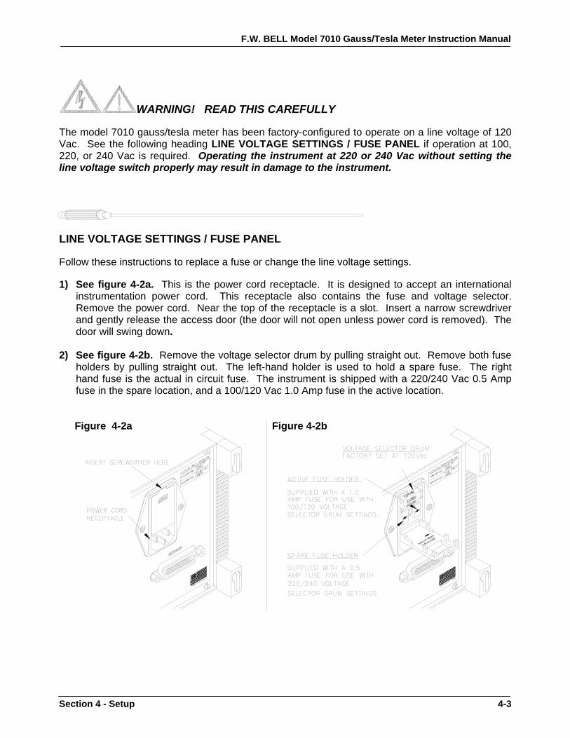
WARNING! READ THIS CAREFULLY The model 7010 gauss/tesla meter has been factory-configured to operate on a line voltage of 120 Vac. See the following heading LINE VOLTAGE SETTINGS / FUSE PANEL if operation at 100, 220, or 240 Vac is required. Operating the instrument at 220 or 240 Vac without setting the line voltage switch properly may result in damage to the instrument. LINE VOLTAGE SETTINGS / FUSE PANEL Follow these instructions to replace a fuse or change the line voltage settings. 1) See figure 4-2a. This is the power cord receptacle. It is designed to accept an international
instrumentation power cord. This receptacle also contains the fuse and voltage selector. Remove the power cord. Near the top of the receptacle is a slot. Insert a narrow screwdriver and gently release the access door (the door will not open unless power cord is removed). The door will swing down.
2) See figure 4-2b. Remove the voltage selector drum by pulling straight out. Remove both fuse
holders by pulling straight out. The left-hand holder is used to hold a spare fuse. The right hand fuse is the actual in circuit fuse. The instrument is shipped with a 220/240 Vac 0.5 Amp fuse in the spare location, and a 100/120 Vac 1.0 Amp fuse in the active location.
Figure 4-2a Figure 4-2b
F.W. BELL Model 7010 Gauss/Tesla Meter Instruction Manual
4-4 Section 4 - Setup
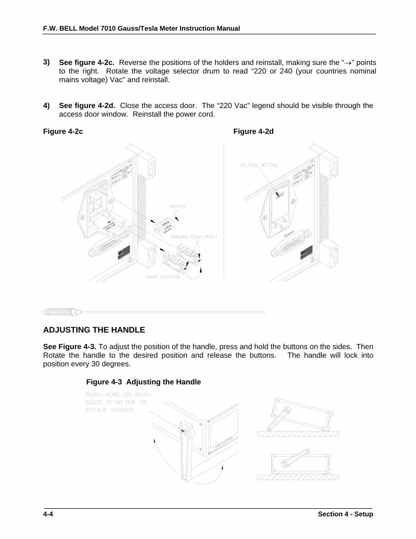
3)
See figure 4-2c. Reverse the positions of the holders and reinstall, making sure the “→” points to the right. Rotate the voltage selector drum to read “220 or 240 (your countries nominal mains voltage) Vac” and reinstall.
4) See figure 4-2d. Close the access door. The “220 Vac” legend should be visible through the
access door window. Reinstall the power cord.
Figure 4-2c Figure 4-2d ADJUSTING THE HANDLE See Figure 4-3. To adjust the position of the handle, press and hold the buttons on the sides. Then Rotate the handle to the desired position and release the buttons. The handle will lock into position every 30 degrees.
Figure 4-3 Adjusting the Handle

F.W. BELL Model 7010 Gauss/Tesla Meter Instruction Manual
Section 4 - Setup 4-5
PROBE INSTALLATION / REMOVAL
See Figure 4-4 Install the probe connector so that the molded key in the connector body lines up with a similar key-way in the receptacle on the front panel. Push the connector in until it will travel no further. The connector will lock into place. There is no twist lock so it is not necessary to rotate any part of the connector. To remove the connector, grab at the collar and slide back. The probe connector cannot be removed by pulling only on the connector body. Note: You may install or remove a probe at any time, although it is not recommended to do so during the zeroing operation. For more information on probes, see Section 3 – Probes.
Figure 4-4 Installing and Removing Probes

F.W. BELL Model 7010 Gauss/Tesla Meter Instruction Manual
4-6 Section 4 - Setup
POWER - UP Locate the power switch on the front panel. The On/Off positions are labeled
below the switch and are shown in Figure 4-5. To turn on the instrument press the switch and release. The switch will remain depressed and the boot up procedure will begin. To shut the instrument off, press the power switch again and release. Note: Allow three seconds for the instrument to be off before turning it back on.
Figure 4-5 Power Switch Positions

F.W. BELL Model 7010 Gauss/Tesla Meter Instruction Manual
Section 4 - Setup 4-7
BIOS VERSION
STATUS BAR
CPU TYPE
POWER – UP (Continued)
Initialization During Boot up, the F.W. BELL logo will appear and a status bar indicates boot up progress. See Figure 4-6. Internal diagnostics are performed first, followed by the initial formatting of the display. Figure 4-6 Boot Up Screen Calibration data stored in the instruments memory and its probe are retrieved next. The message “Reading Probe” is displayed during this process. If no probe is connected, the message “No Probe” will be displayed. If any of the internal diagnostic tests fail, an error message will appear and the instrument will halt the power-up procedure.
Upon successful completion of the diagnostics and initial calibration, the instrument will be ready to use. Active keys on the front panel are illuminated and present flux density readings and status are displayed. Other parameters, such as range settings, AC/DC, hold, etc. will be initialized to the same condition they were in when the instrument was last turned off. More information on saving configuration settings is presented in SECTION 5 – User Interface. Note: It is recommended that the instrument warm-up for at least fifteen (15) minutes to achieve rated accuracy.

F.W. BELL Model 7010 Gauss/Tesla Meter Instruction Manual
4-8 Section 4 - Setup
This Page Intentionally Blank

F.W. BELL Model 7010 Gauss/Tesla Meter Instruction Manual
Section 5 – User Interface 5-1
Section 5 User Interface OVERVIEW
Most of the features and functions of the 7010 are activated directly from the front panel keypad. Other functions are accessed through the menu system. Operation and general considerations relating to flux density measurements are discussed in Section 6 – Flux Density Measurement.

F.W. BELL Model 7010 Gauss/Tesla Meter Instruction Manual
5-2 Section 5 – User Interface
Menu Keys Channel Keys
FRONT PANEL KEYPAD
There are two sets of keys on the 7010 front panel. One set is associated with the menu system. This set contains the MENU, ENTER, and DIRECTIONAL keys. The other set is associated with flux density measurement operations. This set contains the RANGE, AC/DC, HOLD, RESET, RELATIVE, ZERO, and two MANUAL ADJUST keys. See Figure 5-1. Figure 5-1 Front Panel Keys Each key features a back-light that will illuminate indicating that it is active. In some instances, certain keys will flash indicating that a particular function is enabled or that some condition requires attention. See page 1-6 for a complete diagram of the front panel.

F.W. BELL Model 7010 Gauss/Tesla Meter Instruction Manual
Section 5 – User Interface 5-3
Button
Checkbox
Text
Pointer
Selection
MENU SYSTEM The menu system of the 7010 is very intuitive to use. It features many items that are similar to those found in the operating systems of personal computers. These items include the “pointer”, “buttons”, “checkboxes”, “selections”, and simple text. The menu items are shown in Figure 5-2. Figure 5-2 Menu items Pointer The “pointer” ( ) is moved by using the directional arrow keys. Specific DIRECTION keys, when illuminated, indicate that it is possible to move the “pointer” in those directions. A menu item will flash when it is made active. Only one menu item may be active at a time. Buttons “Buttons” are used to initiate a particular action such as entering into a sub-menu. To activate a “button”, position the “pointer” over the “button” and press the ENTER key. Checkboxes The status of a “checkbox” ( ) may be either checked or unchecked. A checked “checkbox” indicates that a function is enabled. An unchecked “checkbox” indicates that a function is disabled. To change the status of a “checkbox”, position the pointer over the “checkbox” and press the ENTER key.

F.W. BELL Model 7010 Gauss/Tesla Meter Instruction Manual
5-4 Section 5 – User Interface
Position Pointer Over Selection
Press Enter Key, the Selection Advances to the Next Choice
2.
1.
MENU SYSTEM (Continued)
Selections “Selections” contain the possible choices for a function. For example, the possible settings for an analog filter are ”Auto”, “500 Hz”, “5kHz”, and “50kHz.” If the current setting is “500Hz”, positioning the “pointer” over the “selection” and pressing the ENTER key will advance the setting to “5kHz.” See Figure 5-3. When the last choice in a “selection” is reached, pressing the ENTER key will restart the “selection” choices. Figure 5-3 Using Selections Numbers Numbers act as groups of “selections” where the possible choices for each digit in the number are the numerals 0-9. Entering The Menu System Pressing the MENU key from the measurement screen will access the main menu. The main menu is shown in Figure 5-4. To return to the measurement screen, press the MENU key again. Figure 5-4 Main Menu To enter a sub-menu, position the “pointer” over a “button” and press the ENTER key. To return to the main menu, press the MENU key.

F.W. BELL Model 7010 Gauss/Tesla Meter Instruction Manual
Section 5 – User Interface 5-5
USING THE MOUSE
As an option, the 7000 series supports the use of a Microsoft® compatible serial mouse. The mouse must use a female DB9 female connector. A 9-pin male to 9-pin male gender changer and null modem adapter is also required.
Item Description Radioshack® Catalog # Microsoft® Basic Mouse Cat.#: 950-1077 DB9 Male to DB9 Female Null Modem Cat.#: 26-264
DB9 Male to DB9 Male Gender Changer. Cat.#: 950-0256 Note: Since the mouse uses the RS-232C serial communications port,
it is not possible to use the mouse and support RS-232C communications at the same time. Note: The front panel keypad remains active at all times. The 7010 can be completely operated from the mouse. Pressing the right mouse button is the same as pressing the MENU key on the front panel. Moving the mouse will cause the “pointer” to move about the screen. In the menu system, pressing the left mouse button is the same as pressing the ENTER key. Pressing the left mouse button from the measurement view will display an image of the front panel channel keys. At this point moving the “pointer” over one of the images of a front panel key and pressing the left mouse button will have the same effect as pressing the key itself. Pressing the right mouse button returns to the measurement view. To enable the mouse:
1) From the main menu, choose COMMUNICATIONS. 2) Position the “pointer” over the “checkbox” next to the label “Mouse
Enabled”, and press the ENTER key.

F.W. BELL Model 7010 Gauss/Tesla Meter Instruction Manual
5-6 Section 5 – User Interface
HELP SYSTEM The 7010 features a comprehensive help system. Each sub-menu has a
help screen that can be accessed by “pressing” the “?” “button” in the upper right corner of the screen. These help screens contain information about the functions of the sub-menu from which the help screen was accessed. More general information about the instrument is accessed by pressing the “help” “button” from the main menu. To return to a sub-menu from a help screen, press the MENU key on the front panel.
SYSTEM MENU
The SYSTEM menu provides information on the firmware version and probe connected to the instrument. It is also from the SYSTEM menu that configuration setups may be saved and recalled, See the next heading SETUP SAVE-LOAD. Firmware Version The firmware version is provided to assist in servicing or updating the instrument. Probe Information Probe information includes the following:
1) Whether or not a Probe is Connected. 2) Probe Model Number. 3) Probe Serial Number. 4) Probe Calibration Date.
F.W. BELL Model 7010 Gauss/Tesla Meter Instruction Manual
Section 5 – User Interface 5-7
SETUP SAVE-LOAD
Four (4) configuration setups may be saved in flash memory. These setups may be recalled at anytime, including after the instrument has been shut off. All settings from all menus are saved including those enabled from the front panel keypad. To Save and Load a Configuration Setup
1) From the main menu, choose SYSTEM.
2) To save the current setup: Move the “pointer’” to one of the “buttons” numbered 1-4 next to the word “Save”, and press the ENTER key.
3) To load the corresponding setup: Move the “pointer” to the “button” with the same number next to the word “Load”, and press the ENTER key.
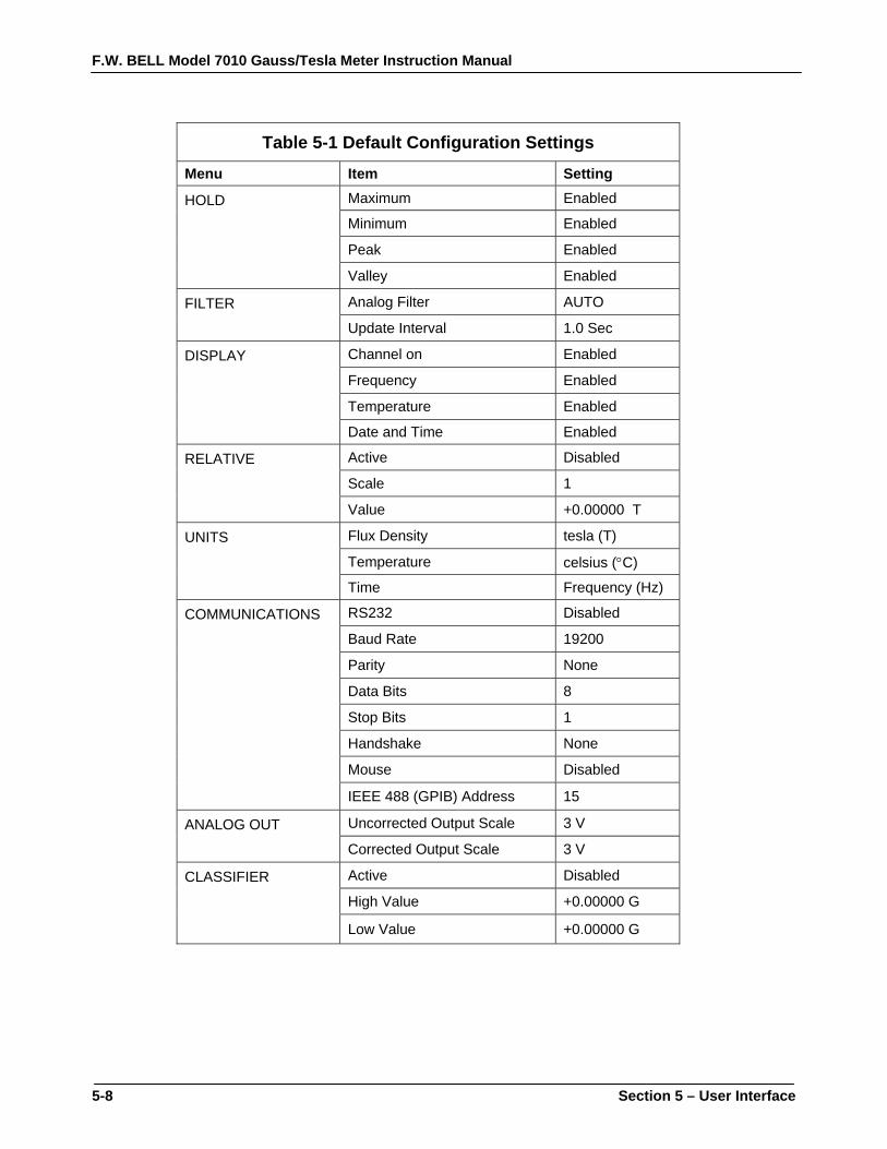
To Select Default Settings Default settings are shown in Table 5-1.
1) From the main menu, choose SYSTEM.
2) Move the “pointer” to the “button” labeled “Default”, and press the ENTER key.
F.W. BELL Model 7010 Gauss/Tesla Meter Instruction Manual
5-8 Section 5 – User Interface
Table 5-1 Default Configuration Settings
Menu Item Setting
HOLD Maximum Enabled
Minimum Enabled
Peak Enabled
Valley Enabled
FILTER Analog Filter AUTO
Update Interval 1.0 Sec
DISPLAY Channel on Enabled
Frequency Enabled
Temperature Enabled
Date and Time Enabled
RELATIVE Active Disabled
Scale 1
Value +0.00000 T
UNITS Flux Density tesla (T)
Temperature celsius (°C)
Time Frequency (Hz)
COMMUNICATIONS RS232 Disabled
Baud Rate 19200
Parity None
Data Bits 8
Stop Bits 1
Handshake None
Mouse Disabled
IEEE 488 (GPIB) Address 15
ANALOG OUT Uncorrected Output Scale 3 V
Corrected Output Scale 3 V
CLASSIFIER Active Disabled
High Value +0.00000 G
Low Value +0.00000 G

F.W. BELL Model 7010 Gauss/Tesla Meter Instruction Manual
Section 5 – User Interface 5-9
DISPLAY FORMAT
The instrument will automatically format the screen for the best possible view based on the number of parameters enabled. Table 5-2 summarizes the various display options.
Table 5-2 Display Options
Parameter Displayed Comments
Present Flux Density Always Larger Than All Other parameters
Range Always
AC/DC Always
Temperature Optional Enabled from DISPLAY Menu (Temperature Compensated Probes only)
Frequency Optional Enabled from DISPLAY Menu ( ac Mode Only)
Relative Optional Enabled from RELATIVE Menu or Front Panel Keypad
Hold
Minimum Optional
Display of these parameters are selected from the HOLD menu. However the selected parameters are displayed only when the HOLD key on the front panel is activated.
Maximum Optional
Peak Optional
Valley Optional
Date Optional Enabled and Set from DISPLAY Menu
Time Optional

F.W. BELL Model 7010 Gauss/Tesla Meter Instruction Manual
5-10 Section 5 – User Interface
SETTING THE DATE AND TIME
The date and time is set and enabled from the display menu. When enabled, the date and time is displayed at the bottom of the measurement screen. To enable / disable the date and time for display
1) From the main menu, choose DISPLAY. 2) The date and time each have a “checkbox”. Position the “pointer”
over the appropriate “checkbox” and press the ENTER key. To Set the date and time
1) From the main menu, choose DISPLAY. 2) Position the “pointer” over each digit in the date and time. 3) Press the ENTER key to change the setting. 4) AM, PM, or MIL (for military time, 24 Hours) is selected by
positioning the “pointer” over the “selection” and pressing the ENTER key.
F.W. BELL Model 7010 Gauss/Tesla Meter Instruction Manual
Section 6 – Flux Density Measurement 6-1
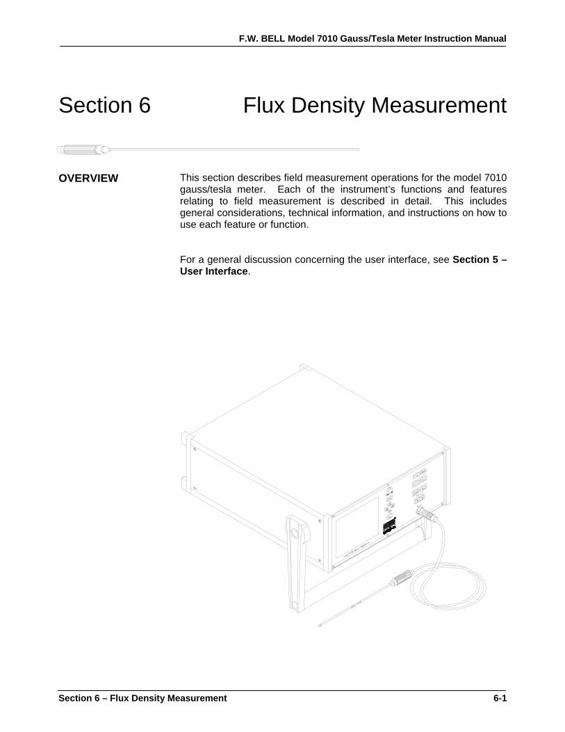
Section 6 Flux Density Measurement OVERVIEW
This section describes field measurement operations for the model 7010 gauss/tesla meter. Each of the instrument’s functions and features relating to field measurement is described in detail. This includes general considerations, technical information, and instructions on how to use each feature or function. For a general discussion concerning the user interface, see Section 5 – User Interface.

F.W. BELL Model 7010 Gauss/Tesla Meter Instruction Manual
6-2 Section 6 – Flux Density Measurement
MEASUREMENT UNITS
The measurement units selected are displayed at the bottom of the measurement screen. Table 6-1 lists the available units for each parameter.
Table 6-1 Available Units Quantity Units Flux Density gauss ( G)
tesla (T) oersted (Oe) ampere / meter (A / m)
Temperature fahrenheit (°F) celsius (°C) kelvin (°K)
Time (Frequency / Period ) hertz ( Hz ) seconds ( Sec )
Setting the Units To change the units:
1) From the main menu, choose UNITS. 2) For each quantity, position the “pointer” over the appropriate
“checkbox” and press the ENTER key.

F.W. BELL Model 7010 Gauss/Tesla Meter Instruction Manual
Section 6 – Flux Density Measurement 6-3
Units
Polarity IndicatorFlux Density Reading
+ 12.345 KG
PRESENT FLUX DENSITY READING
The flux density reading contains five or six digits of information and includes the decimal point, polarity information, and the units of measurement; see Figure 6-1. The number of digits depends on the update interval setting. The update interval is discussed later in this section. The present flux density reading is always displayed with a larger text size than any other parameter. In the dc mode of operation, the polarity is indicated with a “+” or a “-“. The polarity information is absent when in ac mode, unless relative mode is enabled. Relative mode operation is discussed later in this section. Note: The reading displayed in ac mode will represent the true rms value of the field waveform. Figure 6-1 Present Flux Density Reading
MEASUREMENT MODE INDICATOR
The measurement mode is always displayed on a separate line, see Figure 6-2. It indicates the measurement range, if autorange mode is active, and whether ac or dc mode is selected. If autorange mode is active the word “Auto” is displayed. Figure 6-2 Measurement Mode Indicator
Auto 30G DC Autorange mode Present Range
ac or dc Mode

F.W. BELL Model 7010 Gauss/Tesla Meter Instruction Manual
6-4 Section 6 – Flux Density Measurement
RANGE SELECTION
The instrument is capable of providing flux density measurements on one of four fixed ranges, or it can be programmed to automatically select the best range for the present flux density being measured. The available ranges are listed in Section 2 – Specifications. The ranges advance in decade steps, the magnitudes available depend on the probe type. The lowest range offers the best resolution while the highest range allows higher flux density levels to be measured. Setting the Range Pressing the RANGE key will advance the range setting. The four ranges are followed by the autorange selection. Autorange In the autorange mode, the range is advanced if the reading reaches 90% full scale of the present range. The range is lowered if the present reading falls below 8% full scale of the present range. NOTE: When the word “Auto” does not appear on the “measurement mode indicator” line, the channel is in manual ranging mode. Overrange Condition An overrange condition will occur when the following is true: The instrument is in manual range mode or is in autorange mode at the highest range; and the measured flux density is 110% of the present full scale range. When an overrange condition occurs the instrument will display the message “OverRange” in place of the flux density reading. The next highest range should be selected. If already on the highest range, then the flux density is too great to be measured with this instrument and its probe.
Note: For dc mode operation, the polarity of the flux density that caused the overrange condition will be displayed to the left of the “OverRange” message.

F.W. BELL Model 7010 Gauss/Tesla Meter Instruction Manual
Section 6 – Flux Density Measurement 6-5
AC OR DC MEASUREMENT SELECTION
To Switch Between ac or dc Mode The instrument is capable of measuring either static (dc) or alternating (ac) magnetic fields. To choose the desired mode, press the AC/DC key. The “measurement mode indicator” indicates the present mode.
AC MODE OPERATION
It is possible for the flux density signal to contain both a dc component and an ac component. In the ac mode the value displayed is the true rms value of the waveform with its dc component removed. Frequency Measurement When used in the ac mode, the instrument can display the frequency of an ac field. The frequency indicator line displays the measured frequency and the selected analog filter setting, see Figure 6-3. Analog filters are discussed later in this section.
Figure 6-3 Frequency / 1.234kHz f50k Filter Indicator Frequency Reading Units Filter Setting
To enable / disable frequency measurements:
1) From the main menu, choose DISPLAY. 2) Position the “pointer” over the appropriate “checkbox” in the row
labeled “Frequency” and press the ENTER key. Note: Depending on the selection in the UNITS menu, frequency or period may be displayed.

F.W. BELL Model 7010 Gauss/Tesla Meter Instruction Manual
6-6 Section 6 – Flux Density Measurement
AC MODE OPERATION (Continued)
Frequency Compensation in ac Mode To obtain accurate ac measurements using frequency compensation, the ac field must have a frequency greater than 10 Hz, and depending on the selected range, a minimum magnitude according to Table 6-2.
Table 6-2 Minimum Magnitudes for Rated ac Accuracy Range
Minimum MagnitudeLow Field Probe Mid Field Probe High Field Probe
300.000 mG (30.0000 µT) 30.0000 G (3.00000 mT) 300.000 G (30.0000 mT) 20% Full Scale 3.00000 G (300.000 µT) 300.000 G (30.0000 mT) 3.00000 kG (300.000 mT 6% Full Scale
N/A 3.00000 kG (300.000 mT) 30.0000 kG (3.00000 T) 4% Full Scale N/A 30.0000 kG (3.00000 T) 300.000 kG (30.0000 T) 2% Full Scale
If the measured magnetic field is less than the “minimum magnitude”
shown on Table 6-2, fourth column; the frequency of the magnetic field cannot be measured. In that case, the frequency indicator will display dashes. See Figure 6-4. Figure 6-4 Indeterminate Frequency Indicator ------Hz f5k Note: Although the flux density reading will be displayed when the frequency is indeterminate, it is not specified at rated accuracy.
F.W. BELL Model 7010 Gauss/Tesla Meter Instruction Manual
Section 6 – Flux Density Measurement 6-7
AC MODE ANALOG FILTERING
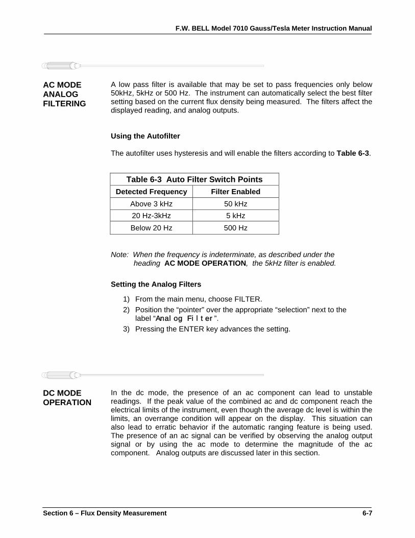
A low pass filter is available that may be set to pass frequencies only below 50kHz, 5kHz or 500 Hz. The instrument can automatically select the best filter setting based on the current flux density being measured. The filters affect the displayed reading, and analog outputs. Using the Autofilter The autofilter uses hysteresis and will enable the filters according to Table 6-3.
Table 6-3 Auto Filter Switch Points Detected Frequency Filter Enabled
Above 3 kHz 50 kHz 20 Hz-3kHz 5 kHz Below 20 Hz 500 Hz
Note: When the frequency is indeterminate, as described under the
heading AC MODE OPERATION, the 5kHz filter is enabled. Setting the Analog Filters
1) From the main menu, choose FILTER. 2) Position the “pointer” over the appropriate “selection” next to the
label “Analog Filter”. 3) Pressing the ENTER key advances the setting.
DC MODE OPERATION
In the dc mode, the presence of an ac component can lead to unstable readings. If the peak value of the combined ac and dc component reach the electrical limits of the instrument, even though the average dc level is within the limits, an overrange condition will appear on the display. This situation can also lead to erratic behavior if the automatic ranging feature is being used. The presence of an ac signal can be verified by observing the analog output signal or by using the ac mode to determine the magnitude of the ac component. Analog outputs are discussed later in this section.
F.W. BELL Model 7010 Gauss/Tesla Meter Instruction Manual
6-8 Section 6 – Flux Density Measurement
ZEROING
Overview “Zeroing” the probe and instrument is one of the most important steps to obtaining accurate flux density measurements. An ideal Hall effect sensor produces zero output in the absence of a magnetic field, but actual devices are subject to variations in materials, construction and temperature. Therefore, most Hall effect sensors produce some output even in a zero field. This will be interpreted by the instrument as a magnetic field signal. Also, the circuits within the instrument can produce a signal even when there is no signal present at the input. This will also be interpreted as a magnetic field by the instrument. Lastly, magnetic sources close to the actual field being measured, such as those from electric motors, permanent magnets and the earth’s magnetic field (roughly 0.5 gauss or 50 µT), can introduce errors in the final reading. The zero operation is performed for both ac and dc modes of operation. While in dc mode, the zero point can be adjusted manually. When the zeroing process is initiated, the instrument performs separate zeroing sequences for ac and dc mode operation. Both sequences occur regardless of whether a channel is in ac or dc mode, and each has its own considerations. NOTE: The process of zeroing also affects other functions such as corrected analog output signals, the hold and relative, and the field classifiers. Uncorrected analog outputs are not affected. ac Zeroing There are two modes of ac zeroing, basic and advanced. For most purposes, basic ac mode zeroing is sufficient and is set as the default. Basic ac mode zeroing is performed internal to the instrument and is not affected by the presence of magnetic fields. The use of a “zero flux chamber” is not required for basic ac mode zeroing. This is advantageous for situations when the probe is to be purposely exposed to a magnetic field during zeroing. This situation is described under the next sub-heading dc Zeroing. Advanced ac zeroing is only required when measuring ac fields on the lower ranges of the instrument. Advanced ac mode zeroing is enabled from a “checkbox” in the SYSTEM menu. This mode requires a substantially longer zeroing period, but is required for rated ac accuracy on the lower ranges. The probe must be shielded in a “zero flux chamber” prior to initiating the zeroing procedure when using advanced ac zeroing. Typically it is only necessary to use advanced ac zeroing once when a new probe is installed. Advanced ac zeroing data for the probe is stored, including after the instrument has been shut off. The advanced ac zeroing mode may then be disabled, and basic ac zeroing used thereafter. The only exception is when continued measurement of low range ac fields are being made.

F.W. BELL Model 7010 Gauss/Tesla Meter Instruction Manual
Section 6 – Flux Density Measurement 6-9
ZEROING (Continued)
dc Zeroing For most situations it is preferable to shield the probe from all external magnetic fields prior to zeroing. Provided with the instrument is a “zero flux chamber” which is capable of shielding against fields as high as 30 mT (300 G or 23.88 kA/m). The probe is simply inserted into the chamber before the zeroing process begins.
Handle the Hall probe with care. Do not bend the stem or apply pressure to the probe tip as damage may result. In other situations the user may want the probe to be exposed to a specific magnetic field during the zeroing process. As an example, consider zeroing the probe when it is exposed to the earth’s magnetic field. This will cancel the effect of the earth’s magnetic field for all future readings. If a range is exceeded by the level of field while zeroing, the lower range cannot be entered by the instrument. Zero Prompt The instrument will inform the user to zero a channel by flashing the ZERO key on the front panel. The following are the conditions that will cause the instrument to prompt the user to initiate the zeroing process: • The instrument was just turned on. • A probe was just inserted into the instrument. • Fifteen (15) minutes has elapsed since the instrument was turned on. • Fifteen (15) minutes has elapsed since a probe has been inserted. • The instrument’s internal temperature has drifted by at least 5°C. Initiating Zeroing To initiate the zeroing process:
1) Prepare the probe for zeroing. 2) Press the ZERO key.
The instrument will display the message “Zeroing” and a countdown indicates the approximate duration of the zeroing process. Once zeroing begins it must be allowed to complete. During this time, all controls are disabled except for the power switch. The zeroing process is approximately 60 seconds when basic ac mode zeroing is enabled and is approximately 2 minutes for advanced ac mode zeroing.
F.W. BELL Model 7010 Gauss/Tesla Meter Instruction Manual
6-10 Section 6 – Flux Density Measurement
ZEROING (Continued)
Manual Zero Offset for dc Mode Operation This feature also allows the user to manually set the zero point to a value other than zero or to make a fine adjustment to the zero point after performing a zeroing operation. To manually adjust the zero point:
1) Position the probe for zeroing.
2) Use the MANUAL ADJUST keys to adjust the zero point to the desired setting. The right MANUAL ADJUST key adds to the reading, the left MANUAL ADJUST key subtracts from the reading.
See page 1-6 for a diagram of the front panel.
This value will be added to (or subtracted from) all future dc readings. The manual offset operation affects dc offsets only, therefore it can only be used when dc mode is selected. If you wish to suppress an ac field, consider using the relative mode. NOTE: Making a manual adjustment to the zero point only affects the current range. Adjustment may need to be repeated for other ranges.
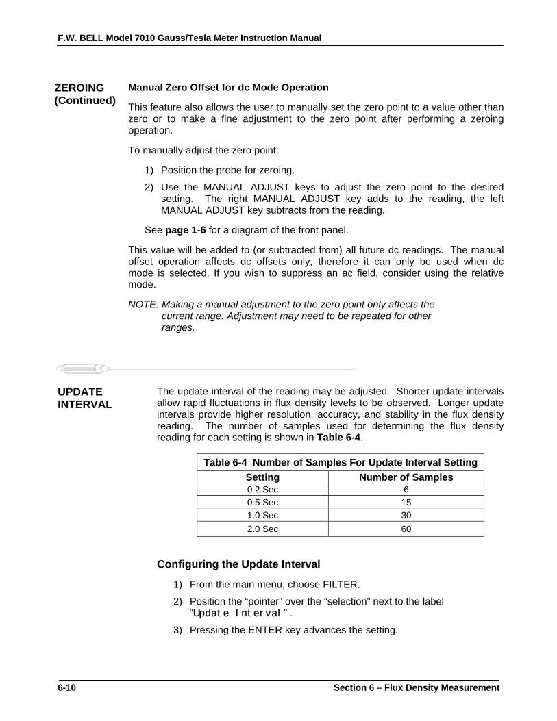
UPDATE INTERVAL
The update interval of the reading may be adjusted. Shorter update intervals allow rapid fluctuations in flux density levels to be observed. Longer update intervals provide higher resolution, accuracy, and stability in the flux density reading. The number of samples used for determining the flux density reading for each setting is shown in Table 6-4.
Table 6-4 Number of Samples For Update Interval Setting
Setting Number of Samples 0.2 Sec 6 0.5 Sec 15 1.0 Sec 30 2.0 Sec 60
Configuring the Update Interval
1) From the main menu, choose FILTER.
2) Position the “pointer” over the “selection” next to the label “Update Interval”.
3) Pressing the ENTER key advances the setting.

F.W. BELL Model 7010 Gauss/Tesla Meter Instruction Manual
Section 6 – Flux Density Measurement 6-11
HOLD FUNCTION
In some applications it may be desirable to “hold” a reading that is either greater than (MAX hold) or less than (MIN hold) all previous readings. Also, it may be necessary to capture the high (PEAK hold) and low (VALLEY hold) extremes of rapidly changing pulses. The hold functions will hold their readings until reset by the user. MIN and MAX HOLD General Description The MIN and MAX hold functions are useful in determining the maximum or minimum value of magnetic events that occur over a period of time. The MIN and MAX use readings that are arithmetically calculated by the instrument for slow changing signals. The MAX hold function holds the reading that is arithmetically greater than all previous readings. For instance, a reading of +125.0 is greater than +99.0 or –150.0. The MIN hold function holds the reading that is arithmetically less than all previous readings. For instance, a reading of -125.0 is less than -99.0 or +150.0. If the reading exceeds the limit of the selected range the MIN and MAX functions will display “OverRange” in place of minimum and maximum flux density readings. PEAK and VALLEY General Description PEAK and VALLEY hold modes are used to track rapid events such as magnetizing pulses. Unlike MIN and MAX, PEAK and VALLEY are not arithmetically processed by the instrument. They represent the extremes of a flux density waveform that have been captured within the response times of the instrument. The response times of these functions are listed in Section 2 – Specifications. Numerically, The PEAK hold function holds it’s reading the same as the MAX hold function. The PEAK hold function holds the reading greater than all previous readings, within the response time of the instrument. For instance, a reading of +125.0 is greater than +99.0 or –150.0. Numerically, The VALLEY hold function holds it’s reading the same as the MIN hold function. The VALLEY hold function holds the reading that is lower than all previous readings, within the response time of the instrument. For instance, a reading of -125.0 is less than -99.0 or +150.0.

F.W. BELL Model 7010 Gauss/Tesla Meter Instruction Manual
6-12 Section 6 – Flux Density Measurement
HOLD FUNCTION (Continued)
Hold Mode Configuration The hold functions are setup for use from the hold menu and are then activated and reset from the front panel. Any of the various hold functions may be enabled for display. To enable / disable a hold function:
1) From the main menu, choose HOLD. 2) Position the “pointer” of the “checkbox” and press the ENTER key.
Using the HOLD functions To activate / de-activate the hold functions:
1) From the measurement screen, press the HOLD key. The HOLD key will flash indicating that the hold function is active. Hold functions that are enabled in the HOLD menu will be displayed. Pressing the HOLD key again will de-activate the hold function. To reset the hold function:
1) With the hold function active, press the RESET key. Note: The hold functions are reset automatically when they are activated. (i.e. the “held” readings are not saved when the hold functions are de-activated).

F.W. BELL Model 7010 Gauss/Tesla Meter Instruction Manual
Section 6 – Flux Density Measurement 6-13
RELATIVE MODE The relative mode allows a specific flux density value to be subtracted
from all future readings. Thus all future readings will be “relative” to that value. For instance if the relative value is +100.0 gauss, and the present flux density is +112.0 gauss, the actual displayed value will be +12.0 gauss. If the flux density drops to +77.0 gauss, the actual displayed value will be -23.0. Thus the relative mode allows for the direct readout of variations around a given field, whether static (dc) or alternating (ac). There are two ways to generate a relative value. When the RELATIVE key on the front panel is pressed, the instrument uses the present flux density reading from the probe as the relative value. Alternatively, you may specify a pre-determined value from the RELATIVE menu. There may be situations when the user may prefer to shield the probe from all external magnetic fields prior to performing a relative operation. Provided with the instrument is a “zero flux chamber” which is capable of shielding against fields as high as 30 mT (300 G or 23.88 kA/m). The probe is simply inserted into the chamber before the relative operation begins.
Handle the Hall probe with care. Do not bend the stem or apply pressure to the probe tip as damage may result. Relative and ac Mode Operation In normal operation, ac readings do not indicate a polarity as they represent the true rms magnitude of the flux density reading. With the relative mode however, the polarity indicates whether the magnitude of the measured ac field is greater or less than the relative value. For example, if the relative value is 100.000 gauss ac and the measured flux density is 90.000 gauss ac, the displayed reading will be –10.000G. Note: The relative value in ac mode is always positive, the relative reading may be positive or negative. Note: The relative mode is cancelled if the probe is disconnected, if the instrument is turned off and back on again, or if the instrument is switched between ac and dc modes.

F.W. BELL Model 7010 Gauss/Tesla Meter Instruction Manual
6-14 Section 6 – Flux Density Measurement
RELATIVE MODE (Continued)
Relative Mode – Front Panel In the automatic mode, the present flux density as seen by the probe is used as the relative value. To use the present flux density as the relative value:
1) Select ac or dc mode. 2) Press the RELATIVE key.
The RELATIVE key will flash to indicate that the relative function is enabled. The “relative value indicator” displays a value that was the present flux density reading before the RELATIVE key was pressed , see Figure 6-5. The present flux density reading should then display a value of zero. All readings from this point forward are “relative” and not absolute. The relative value is subtracted from all future readings. In the relative mode, a reading of zero indicates that the actual flux density being measured is equal to the relative value. Figure 6- 5 Relative Value Indicator Rel +1.23456G To de-activate the relative mode:
1) Press the RELATIVE key. The RELATIVE key will discontinue to flash and the relative value indicator will disappear. All readings from this point forward are now absolute.
F.W. BELL Model 7010 Gauss/Tesla Meter Instruction Manual
Section 6 – Flux Density Measurement 6-15
RELATIVE MODE (Continued)
Relative Mode – Menu System In some cases you may wish to set a pre-determined relative value. The relative value can be set precisely from the menu system. To set a pre-determined relative value from the menu system:
1) Select ac or dc mode.
2) From the main menu, choose RELATIVE.
3) Use the “checkbox” to the relative mode.
4) Position the “pointer” over the word “scale” and press the ENTER key to advance the scale of the relative setting. As you press the ENTER key, the decimal point and/or unit multiplier in the relative setting will advance.
5) For dc mode operation, position the “pointer” over the polarity indicator and press the ENTER key to change the setting.
6) Position the “pointer” over each digit in the relative setting and use the ENTER key to advance the number.
7) Exit the menu system. Upon return to the measurement screen, the relative function is enabled and the ‘relative value indicator” shows the setting selected in the RELATIVE menu. Adjusting the Relative Value from the Measurement Screen Once the relative value is set, either from the front panel or from the RELATIVE menu, its value may be adjusted by using the MANUAL ADJUST keys. The right MANUAL ADJUST key will add to the relative value, and the left MANUAL ADJUST key will subtract from the relative value
F.W. BELL Model 7010 Gauss/Tesla Meter Instruction Manual
6-16 Section 6 – Flux Density Measurement
ANALOG OUTPUTS
A corrected and uncorrected analog output voltage signal available from standard BNC connectors. The uncorrected output signal is representative of the magnetic flux density as measured by the Hall probe. The corrected output signal is compensated for influences of temperature and frequency, as well as non-linearities inherent in the Hall probe and instrument. The corrected output is specified with a higher accuracy than the uncorrected output, with a bandwidth up to 250 Hz. The uncorrected output is less accurate, but has a bandwidth of 50kHz. Standard full scale output ranges are 3VRAW, 10VRAW, 3VRMS, and 10VRMS. Adjustable full scale ranges up to 9.9 VRAW or 9.9VRMS, in increments of 0.1V, are also available. The raw output settings provide voltage signals that are replicas of the magnetic flux density waveforms being measured. The rms settings provide dc voltage signals that are proportional to the rms value of the ac component of a flux density signal. These outputs may be connected to a voltmeter, oscilloscope, recorder, or external analog-to-digital converter. Note: With dc mode operation and rms output settings, only the ac component of the flux density is represented at the analog outputs. See Section 2 – Specifications, for bandwidth and accuracy of the analog outputs. Flux Density Range and Output Voltage Range Full scale of the present flux density range always corresponds to the full scale setting for the analog output voltage range. For example, if the full scale flux density range is 30 gauss and the full scale analog output voltage range is 3 volts; then a reading of 30 gauss will produce a voltage of 3 volts at the output. A reading of -20 gauss will produce a voltage of -2 volts at the output. Using Analog Outputs with Autorange When using autorange and the analog output features together, the following situation can occur. Suppose the present range is 3 kG and the present reading is +2.8 kG. The analog output will be +2.8 Vdc. The signal then increases to +3.2 kG, which would force an automatic change to the 30 kG range setting. The analog output will now be +0.32 Vdc because of the range change. This can lead to problems if the analog signal is being used to make decisions, because there is no indication that a range change has occurred. In these situations it is best to select a fixed range that covers the expected flux density span. Configuring the Analog Outputs
1) From the main menu choose, ANALOG OUTPUTS 2) Position the “pointer” over the appropriate “selection” and press the ENTER
key to advance the setting. 3) For the adjustable setting, position the “pointer” over each digit in the
number and press the ENTER key to advance the setting.

F.W. BELL Model 7010 Gauss/Tesla Meter Instruction Manual
Section 6 – Flux Density Measurement 6-17
CLASSIFIERS The classifier function allows a lower and upper limit of flux density to be
defined that can be quickly used to determine the status of a magnetic field. The instrument will indicate visually whether the field is above, within, or below these limits. The same information is presented in the form of general purpose switch closures available at standard 15 pin “D” type female connector. The connector is located at the rear of the instrument. The pin assignments for the classifier connector (digital I/O) are indicated in Section 2 – Specifications. When the classifier function is enabled the word “Class” will be displayed. If the measured field is below the pre-defined limits, the word “Low” will be displayed next to the word “Class”. If the measured field is above the pre-defined limits, the word “High” will be displayed next to the word “Class”. If the field is within the pre-defined limits, the word “Class” will be displayed by itself. Configuring the Classifier Settings Two flux density values are set. One value sets the upper limit and the other sets the lower limit. It does not matter which value is chosen to be the upper or lower limit, the instrument will automatically make this determination. For dc mode operation, polarity information needs to be specified. With ac mode, only positive values may be set. The instrument will retain dc polarity information when switching between ac and dc modes. To activate / de-activate the classifiers:
1) From the main menu, choose CLASSIFIER. 2) Position the “pointer” over the appropriate “checkbox” and press the
ENTER key. To set the classifier values:
1) From the main menu, choose CLASSIFIER. 2) Position the “pointer” over the word “Scale” and press the ENTER
key to advance the scale of the classifier setting. As the ENTER key is pressed, the decimal point and/or unit multiplier in the classifier setting will advance.
3) For dc mode, position the “pointer” over the polarity indicator and press the ENTER key to change the setting.
4) Position the “pointer” over each digit in the classifier setting and press the ENTER key to advance the number.

F.W. BELL Model 7010 Gauss/Tesla Meter Instruction Manual
6-18 Section 6 – Flux Density Measurement
CLASSIFIERS (Continued)
Example Circuit for Classifier Outputs Figure 6-6 shows an example circuit for using the classifier outputs. These outputs are in the form of general purpose switch closures available from the 15 pin “D” type connector located on the rear panel of the instrument. See Section 2 – Specifications for pin assignments and response times of the relays. If the measured field is within the pre-defined classifier settings, both relays are open and neither LED is illuminated. If the measured field is above the defined limits, the classifier high relay is closed causing the “High” LED to illuminate. If the measured field is below the defined limits, the classifier low relay is closed causing the “Low” LED to illuminate. Figure 6-6 Example Circuit for Classifier Outputs

F.W. BELL Model 7010 Gauss/Tesla Meter Instruction Manual
Section 6 – Flux Density Measurement 6-19
SOURCES OF MEASUREMENT ERROR
When making flux density measurements there are several conditions that can introduce errors: 1) Failure to zero the error signals from the instrument, probe, and nearby sources of magnetic interference. 2) Subjecting the probe to physical abuse. 3) One of the most common sources of error is the angular position of
the probe with respect to the field being measured. A Hall effect sensor is not only sensitive to the number of flux lines passing through it but also the angle at which they pass through it. The Hall effect sensor produces the greatest signal when the flux lines are perpendicular to the sensor as shown in Figure 6-7.
Figure 6-7 Probe Output versus Flux Angle Note: The probe is calibrated and specified with flux lines passing perpendicularly through the Hall effect sensor.
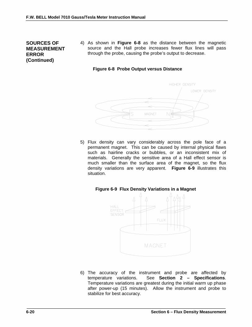
F.W. BELL Model 7010 Gauss/Tesla Meter Instruction Manual
6-20 Section 6 – Flux Density Measurement
SOURCES OF MEASUREMENT ERROR (Continued)
4) As shown in Figure 6-8 as the distance between the magnetic source and the Hall probe increases fewer flux lines will pass through the probe, causing the probe’s output to decrease.
Figure 6-8 Probe Output versus Distance 5) Flux density can vary considerably across the pole face of a
permanent magnet. This can be caused by internal physical flaws such as hairline cracks or bubbles, or an inconsistent mix of materials. Generally the sensitive area of a Hall effect sensor is much smaller than the surface area of the magnet, so the flux density variations are very apparent. Figure 6-9 illustrates this situation.
Figure 6-9 Flux Density Variations in a Magnet 6) The accuracy of the instrument and probe are affected by
temperature variations. See Section 2 – Specifications. Temperature variations are greatest during the initial warm up phase after power-up (15 minutes). Allow the instrument and probe to stabilize for best accuracy.
F.W. BELL Model 7010 Gauss/Tesla Meter Instruction Manual
Section 7 – Remote Operation 7-1
Section 7 Remote Operation INTRODUCTION In 1975 the IEEE-488 standard defined the electrical and mechanical
aspect for cables and connectors, as well as the handshaking, addressing and general protocol for transmitting individual bytes of information between instruments and computers. The standard was later updated and is now called IEEE 488.1-1987. Although the standard solved the problem of how to communicate it did not specify the meaning of the bytes. Instrument manufacturers freely invented new commands as they developed new instruments. For instance a command to program a range on one manufacturer’s voltmeter may not have worked with another’s. Eventually some manufacturers began offering models that recognized other manufacturer’s command sets so that customers could easily switch over without making extensive changes to their programs. The IEEE 488.2-1987 standard was a step toward creating a universal way to communicate with any instrument, regardless of the manufacturer or the type of instrument used. It defined a set of “common” commands that all instruments should respond to in a predictable manner. Yet it did not specify which features or commands should be implemented for a particular instrument. Later the SCPI-1991 standard (Software Commands for Programmable Instruments) defined specific commands and responses that covered a broad range of applications. For a given measurement function such as frequency or voltage, SCPI defines a specific command set that is available for that function. The command sets are easy to learn and read. Manufacturers can still create new commands unique to their own instruments while conforming to the structure and spirit set forth by SCPI. The gauss/tesla meter supports most of the IEEE-488-1987.2 “common” commands as well as a subset of the SCPI-1999.0 commands. Due to the uniqueness of a gauss/tesla meter, there are some commands that are not specified by SCPI but that conform to the rules indicated by the standard. Prior to using the IEEE-488 bus the instrument must be assigned a unique address on the bus. Prior to using the RS-232 serial port parameters such as baud rate and character length must be set to match that of the computer. This is done with the COMMUNICATIONS menu, discussed later in this section.
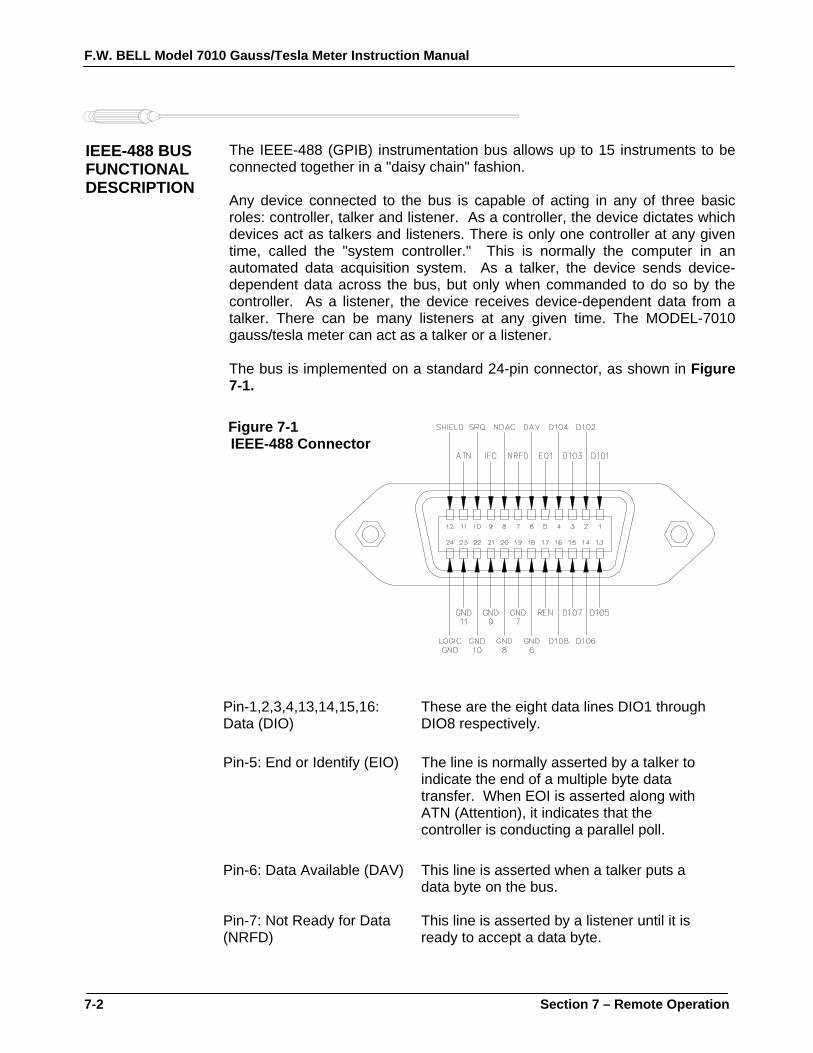
F.W. BELL Model 7010 Gauss/Tesla Meter Instruction Manual
7-2 Section 7 – Remote Operation
IEEE-488 BUS FUNCTIONAL DESCRIPTION
The IEEE-488 (GPIB) instrumentation bus allows up to 15 instruments to be connected together in a "daisy chain" fashion.
Any device connected to the bus is capable of acting in any of three basic roles: controller, talker and listener. As a controller, the device dictates which devices act as talkers and listeners. There is only one controller at any given time, called the "system controller." This is normally the computer in an automated data acquisition system. As a talker, the device sends device-dependent data across the bus, but only when commanded to do so by the controller. As a listener, the device receives device-dependent data from a talker. There can be many listeners at any given time. The MODEL-7010 gauss/tesla meter can act as a talker or a listener.
The bus is implemented on a standard 24-pin connector, as shown in Figure 7-1.
Figure 7-1 IEEE-488 Connector
Pin-1,2,3,4,13,14,15,16: Data (DIO)
These are the eight data lines DIO1 through DIO8 respectively.
Pin-5: End or Identify (EIO) The line is normally asserted by a talker to indicate the end of a multiple byte data transfer. When EOI is asserted along with ATN (Attention), it indicates that the controller is conducting a parallel poll.
Pin-6: Data Available (DAV) This line is asserted when a talker puts a data byte on the bus.
Pin-7: Not Ready for Data (NRFD)
This line is asserted by a listener until it is ready to accept a data byte.

F.W. BELL Model 7010 Gauss/Tesla Meter Instruction Manual
Section 7 – Remote Operation 7-3
IEEE-488 BUS FUNCTIONAL DESCRIPTION (Continued)
Pin-8: Not Data Accepted (NDAC)
This line is asserted by a listener until it has accepted a data byte.
Pin-9: Interface Clear (IFC)
Asserted by the system controller to force all other devices to go idle.
Pin-10: Service Request (SRQ)
This line can be asserted by any device requiring service.
Pin-11: Attention (ATN)
Asserted by the controller to indicate that the byte on the data bus is an interface command.
Pin-12: Not Connected
Pin-17: Remote Enable (REN)
Asserted by the system controller to tell the systems receiving data that they can actually use the data, and that their front panel controls are locked out.
Pin-18,19, 20. 21, 22, 23. 24 Ground (GND)
These are the common return lines for all other signals except earth ground (Pin-12).
Each device on the system bus must be assigned a unique address ranging from 00 to 31 decimal.
RS-232 FUNCTIONAL DESCRIPTION
The instrument has been designed to interface directly to a 9-pin “D” serial connector on most personal computers using a straight-through cable. This means Pin-1 on the meter is connected to Pin-1 on the computer, Pin-2 to Pin-2, etc. The serial transmission characteristics such as baud rate, parity setting, etc. are defined in the COMMUNICATIONS menu. These settings must match those of the computer. A set of controls lines are used to indicate the overall status of the instrument and computer. The instrument asserts the Data-Terminal-Ready (DTR) to inform the computer that it is powered up, initialized and ready for communications. Likewise the computer asserts Data-Set-Ready (DSR) to indicate that it is ready for communications.

F.W. BELL Model 7010 Gauss/Tesla Meter Instruction Manual
7-4 Section 7 – Remote Operation
RS-232 FUNCTIONAL DESCRIPTION (Continued)
Data is transmitted to the instrument on the receive (RX) line. Data is transmitted to the computer on the transmit (TX) line. In most cases these are the only signals needed for communications. However, there may be a need to control the flow of data between the instrument and the computer. For example, if the computer is receiving data from the instrument but is interrupted by another task, it may want to halt the instrument’s transmission until it has completed that task. This can be accomplished in one of two ways. Hardware Handshaking Two lines called Clear-To-Send (CTS) and Request-To-Send (RTS) are used to control the flow of data. This is often referred to as “hardware handshaking”. The instrument will not transmit data until the computer asserts the CTS line. Likewise the computer should not transmit data until the instrument asserts the RTS line. Hardware handshaking can be enabled or disabled from the COMMUNICATIONS menu. It must also be enabled or disabled on the computer. Software Handshaking Another way to control the flow of data is called “software handshaking”. In this method two special characters are used to halt or resume the flow of data. The XOFF character is decimal 19 (hex 13). If the instrument receives the XOFF character at any time it will halt transmission until it receives the XON character, which is decimal 17 (hex 11). Likewise if the instrument transmits an XOFF character to the computer the computer should halt transmission until it receives the XON character. Software handshaking can be enabled or disabled from the COMMUNICATIONS menu. It must also be enabled or disabled on the computer. If disabled the instrument will treat the XON and XOFF characters as any other character. Figure 7-2 RS-232 Connector
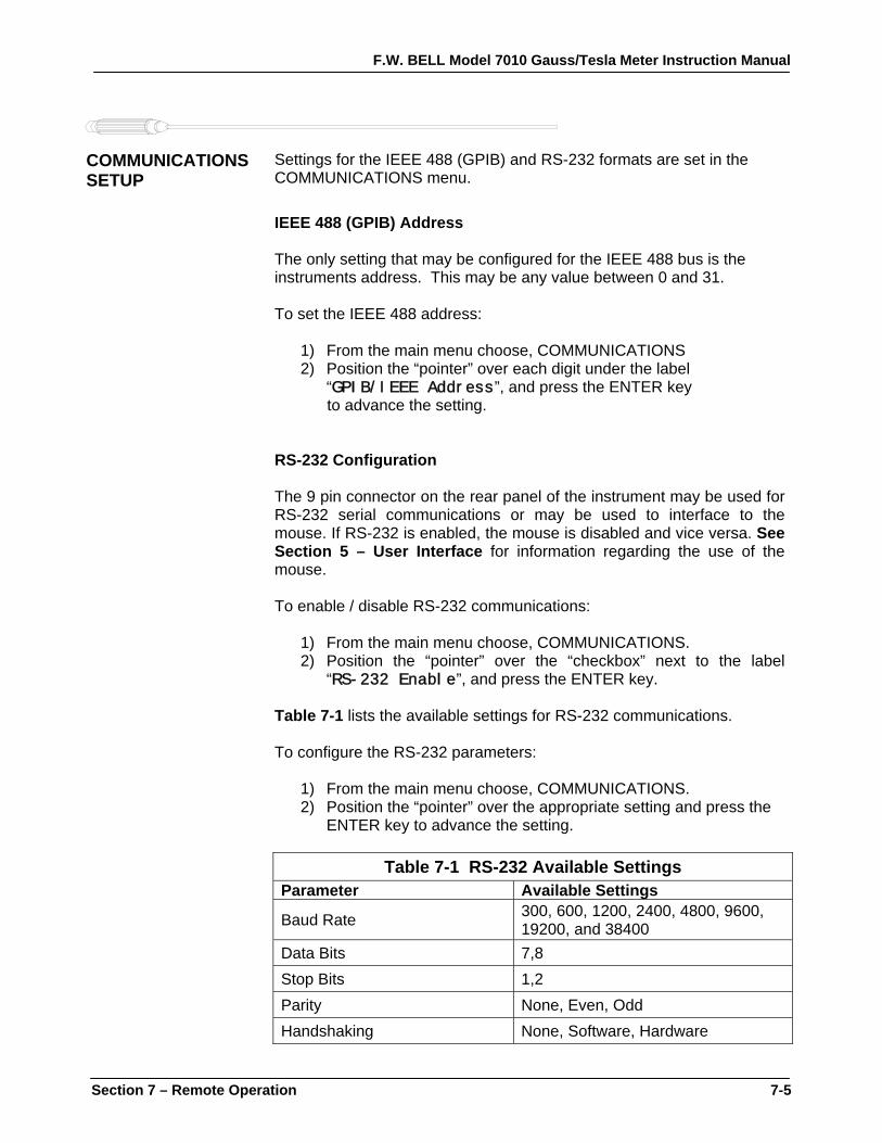
F.W. BELL Model 7010 Gauss/Tesla Meter Instruction Manual
Section 7 – Remote Operation 7-5
COMMUNICATIONS SETUP
Settings for the IEEE 488 (GPIB) and RS-232 formats are set in the COMMUNICATIONS menu. IEEE 488 (GPIB) Address The only setting that may be configured for the IEEE 488 bus is the instruments address. This may be any value between 0 and 31. To set the IEEE 488 address:
1) From the main menu choose, COMMUNICATIONS 2) Position the “pointer” over each digit under the label
“GPIB/IEEE Address”, and press the ENTER key to advance the setting.
RS-232 Configuration The 9 pin connector on the rear panel of the instrument may be used for RS-232 serial communications or may be used to interface to the mouse. If RS-232 is enabled, the mouse is disabled and vice versa. See Section 5 – User Interface for information regarding the use of the mouse. To enable / disable RS-232 communications:
1) From the main menu choose, COMMUNICATIONS. 2) Position the “pointer” over the “checkbox” next to the label
“RS-232 Enable”, and press the ENTER key. Table 7-1 lists the available settings for RS-232 communications. To configure the RS-232 parameters:
1) From the main menu choose, COMMUNICATIONS. 2) Position the “pointer” over the appropriate setting and press the
ENTER key to advance the setting.
Table 7-1 RS-232 Available Settings Parameter Available Settings
Baud Rate 300, 600, 1200, 2400, 4800, 9600, 19200, and 38400
Data Bits 7,8 Stop Bits 1,2 Parity None, Even, Odd Handshaking None, Software, Hardware

F.W. BELL Model 7010 Gauss/Tesla Meter Instruction Manual
7-6 Section 7 – Remote Operation
IEEE-488 GENERAL BUS COMMANDS
General bus commands have the same meaning to any instrument on the IEEE-488 bus. Often the user will be using an IEEE-488 controller card, such as a National Instruments PCI-GPIB. Along with the card a software package is supplied, commonly called a Universal Language Driver (ULD) or a Universal Language Interface (ULI). This software translates the complicated lower level operations into easy-to-use commands. The following commands assume the instrument’s address has been set to 15:
Table 7-2 General Command Summary for IEEE-488
COMMAND ULI STATEMENT BRIEF DESCRIPTION REN REMOTE 15 Enter remote mode, disable front panel controls. IFC ABORT Clears the interface and remote mode. LLO LOCAL LOCKOUT Disable front panel controls. GTL LOCAL 15 Cancel remote mode, restore front panel controls.
DCL CLEAR Cancels all commands, clears all queues, affects all instruments on the bus.
SDC CLEAR 15 Same as DCL, except only for this instrument. SPE, SPD SPOLL 15 Read the serial poll byte.
REN – Remote Enable
This command prepares the instrument for remote operations. All front panel controls are disabled except for the power switch. IFC – Interface Clear This command cancels the remote mode and places the bus in an idle state. LLO – Local Lockout All front panel controls are disabled except for the power switch. GTL - GO TO LOCAL This command cancels remote mode and restores front panel operation.

F.W. BELL Model 7010 Gauss/Tesla Meter Instruction Manual
Section 7 – Remote Operation 7-7
IEEE-488 GENERAL BUS COMMANDS (Continued)
DCL - DEVICE CLEAR This command clears the bus and returns it to a known state. All devices are affected. The instrument will cancel any pending commands and clear its output buffers. Instrument settings are not affected. SDC - SELECTIVE DEVICE CLEAR Same as the DCL command except only for the addressed instrument. SPE,SPD - SERIAL POLL This command obtains the serial poll status byte, which contains important status information about the instrument. Often a serial poll is initiated when one or more devices are asserting an interface line called SRQ (service request).
ERROR QUEUE AND OUTPUT QUEUE
Internally there are two buffers that accumulate messages. Errors are generated by a variety of sources, such as hardware errors or errors in the command syntax. As errors occur messages are stored in an ERROR QUEUE. They can be read by specific commands discussed later in this section. Any time a command requests information from the instrument, such as flux density readings, instrument status or error messages, the information is placed in the OUTPUT QUEUE. They can be read by the system controller using a standard INPUT command.
STATUS There are four register sets that indicate the status of the instrument,
such as errors or the present state of the machine. These are 16-bit registers, but in many cases not all of the bits are used. The four register sets are called: MEASUREMENT EVENT OPERATION EVENT STANDARD EVENT QUESTIONABLE EVENT There is also an 8-bit register that provides a 1-bit summary for each of the four register sets. This is called the STATUS BYTE.
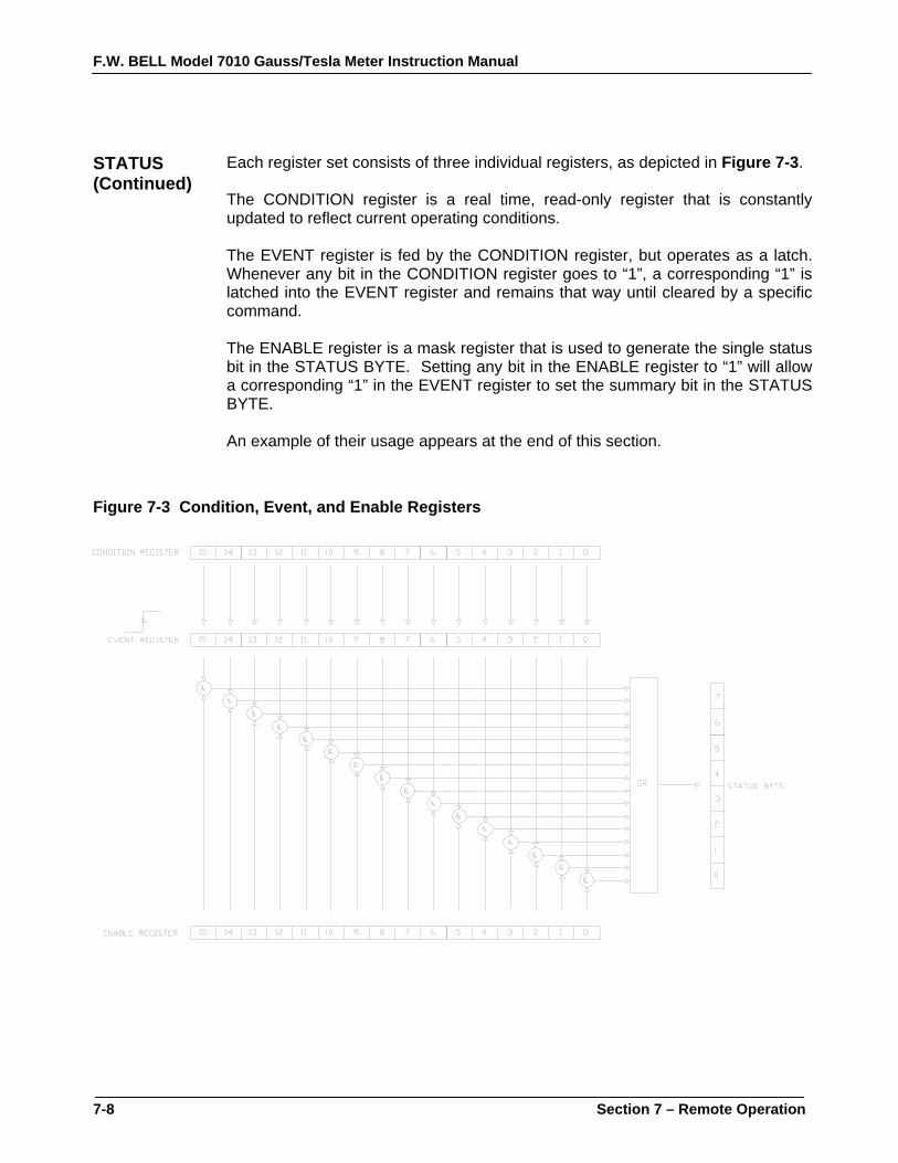
F.W. BELL Model 7010 Gauss/Tesla Meter Instruction Manual
7-8 Section 7 – Remote Operation
STATUS (Continued)
Each register set consists of three individual registers, as depicted in Figure 7-3. The CONDITION register is a real time, read-only register that is constantly updated to reflect current operating conditions. The EVENT register is fed by the CONDITION register, but operates as a latch. Whenever any bit in the CONDITION register goes to “1”, a corresponding “1” is latched into the EVENT register and remains that way until cleared by a specific command. The ENABLE register is a mask register that is used to generate the single status bit in the STATUS BYTE. Setting any bit in the ENABLE register to “1” will allow a corresponding “1” in the EVENT register to set the summary bit in the STATUS BYTE. An example of their usage appears at the end of this section.
Figure 7-3 Condition, Event, and Enable Registers

F.W. BELL Model 7010 Gauss/Tesla Meter Instruction Manual
Section 7 – Remote Operation 7-9
STATUS BYTE AND SERVICE REQUEST (SRQ)
The IEEE-488 bus is a common bus linking a master controller (your computer) to one or more instruments. If an instrument requires action from the controller it must somehow get the controller’s attention. A hardware line on the bus called SRQ (service request) is used to signal the controller that one or more instruments on the bus require attention. A bit in the STATUS BYTE called RQS (request for service) also sets. The master then reads the STATUS BYTE from each instrument to determine which instrument(s) require service. On the RS-232 port there is no hardware method of signaling a service request, so the STATUS BYTE must be inspected (“polled”) to determine if service is required. The RQS bit can set if any of the summary bits from the MEASUREMENT EVENT, OPERATION EVENT, STANDARD EVENT or QUESTIONABLE EVENT registers are set, or if an error or output message is ready to be transmitted to the master. The SRQ ENABLE register is a mask register that is used to allow any of these conditions to set the RQS bit, and thus the SRQ line. Setting any bit in the SRQ ENABLE register to “1” will allow a corresponding “1” in the STATUS BYTE register to set the RQS bit. These registers are depicted in Figure 7-4. An example of their usage appears at the end of this section.
Figure 7-4 Status Byte and SRQ Enable registers

F.W. BELL Model 7010 Gauss/Tesla Meter Instruction Manual
7-10 Section 7 – Remote Operation
STATUS BYTE AND SERVICE REQUEST (SRQ) (Continued)
OSB - Operation Summary Bit: If any of the bits in the OPERATION EVENT register set, and their respective enable bits are set, the Operation Summary Bit (OSB) will set. ESB - Event Summary Bit: If any of the bits in the STANDARD EVENT register set, and their respective enable bits are set, the Event Summary Bit (ESB) will set. QSB - Questionable Summary Bit: If any of the bits in the QUESTIONABLE EVENT register set, and their respective enable bits are set, the Questionable Summary Bit (QSB) will set. MSB - Measurement Summary Bit: If any of the bits in the MEASUREMENT EVENT register set, and their respective enable bits are set, the Measurement Summary Bit (MSB) will set. MAV - Message Available: This bit sets any time there is a message available in the output queue. EAV - Error Available: This bit sets any time there is an error message available in the error queue. RSQ - Request For Service: If any of the other bits in the STATUS BYTE are set, and their respective enable bits are set in the SRQ ENABLE register, the Request For Service (RQS) will set, causing the SRQ interface line to be asserted if using the IEEE-488 bus.

F.W. BELL Model 7010 Gauss/Tesla Meter Instruction Manual
Section 7 – Remote Operation 7-11
STANDARD EVENT REGISTER
If any of these bits set, and their respective enable bits are set, the Event Summary Bit (ESB) will set in the STATUS BYTE.
Figure 7-5 Standard Event register
PON - Power On:
Indicates that the instrument was turned off and on since the last communication. CME - Command Error: Indicates that there was a syntax or spelling error in the command, or the command received is not supported. EXE – Execution Error: Indicates that the instrument detected an error while attempting to execute a command. DDE - Device Dependent Error: Indicates that the instrument did not operate properly due to some internal error. QYE – Query Error: Indicates that an attempt was made to read an empty output queue. OPC - Operation Complete: Indicates that all requested operations have been completed.

F.W. BELL Model 7010 Gauss/Tesla Meter Instruction Manual
7-12 Section 7 – Remote Operation
MEASUREMENT EVENT REGISTER
If any of these bits set, and their respective enable bits are set, the Measurement Summary Bit (MSB) will set in the STATUS BYTE.
Figure 7-6 Measurement Event register
HL - High Limit Exceeded: When the classifier function is enabled these bits indicate that the present reading is higher than the upper classifier limit. LL - Low Limit Exceeded: When the classifier function is enabled these bits indicate that the present reading is below the lower classifier limit. ROF - Reading Overflow: Indicates that the present reading exceeds the measurement range for the instrument. RAV - Reading Available: Indicates a reading is available.

F.W. BELL Model 7010 Gauss/Tesla Meter Instruction Manual
Section 7 – Remote Operation 7-13
OPERATION EVENT REGISTER
If any of these bits set, and their respective enable bits are set, the Operation Summary Bit (OSB) will set in the STATUS BYTE.
Figure 7-7 Operation Event register
IDLE: Indicates the instrument is idle. This condition indicates that there is no probe installed o the channel has been turned off. ZERO: The instrument is presently performing a zeroing operation. MEAS: Indicates the instrument is performing a measurement. RANG: The instrument is presently ranging. CAL: The instrument is presently performing an internal calibration.
QUESTIONABLE EVENT REGISTER
If any of these bits set, and their respective enable bits are set, the Questionable Summary Bit (QSB) will set in the STATUS BYTE.
Figure 7-8 Questionable Event register
CAL: Indicates that an invalid calibration factor was detected during power up or when the probe was installed. The instrument will instead use default parameters. This bit will clear once the instrument and probe have been successfully calibrated.
F.W. BELL Model 7010 Gauss/Tesla Meter Instruction Manual
7-14 Section 7 – Remote Operation
IEEE-488.2 “COMMON” COMMAND SYNTAX
The “common” commands are recognized and acted upon in a similar manner by all IEEE-488.2 instruments, whether a DVM, scope, frequency meter, tesla meter, etc. These are the syntax rules: 1) A common command always begins with an asterisk character (*) followed by a three or four character acronym and possibly one other parameter. For instance a command to reset the instrument is *RST. 2) The commands are not case sensitive. For instance the *RST, *rst and *rSt commands are valid. 3) If there is a fourth character in the acronym it will always be a question mark (?) and indicates that information is being requested from the instrument. For instance a command to read the model number and manufacturer of the instrument is *IDN?. 4) If a parameter follows a command it must be separated from the acronym by at least one space. The parameter is the ASCII representation of a decimal integer. For instance if the parameter to be sent is binary 1100, the actual parameter sent would be the two ASCII characters 12, since binary 1100 = decimal 12. If you were to send the four ASCII characters 1100 it would be interpreted as decimal 1100 (eleven hundred). 5) A number returned from the instrument is an ASCII representation of a decimal integer. For instance if the instrument returns the ASCII string 345 the number is decimal 345 (three hundred forty five), which translates to 159 hex. 6) Multiple commands can be sent in one string. The commands must be separated by semicolons (;). For instance, *RST;*IDN? first resets the instrument and then requests model/manufacturer information. If more than one of the commands in the string requests information from the instrument, the instrument’s response will also have semicolons separating the responses, such as 345;0;10.
F.W. BELL Model 7010 Gauss/Tesla Meter Instruction Manual
Section 7 – Remote Operation 7-15
IEEE-488.2 “COMMON” COMMANDS
Table 7-3 Common Command Summary ACRONYM NAME BRIEF DESCRIPTION
*CLS Clear status Clear all event registers and error queue. *ESE <NRf> Program event enable Program standard event enable register. *ESE? Event enable query Read standard event enable register. *ESR? Event status query Read standard event register and clear it. *IDN? Identification query Return manufacturer, model number, software version
number. *OPC Set operation complete Set the Operation Complete bit in the standard event
register after all pending commands have been executed. *OPC? Operation complete query Places an ASCII “1” in the output queue after all pending
commands have been executed. *OPT? Option identification query Returns information about the probe. *RCL <n> Recall setup Replaces the existing instrument setup with one of four
stored in non-volatile memory. *RST Reset Returns the instrument to a default operating condition. *SAV <n> Save setup Save the existing instrument setup in one of four non-
volatile memory locations. *SRE <NRf> Program SRQ enable Program SRQ enable register. *SRE? SRQ enable query Read SRQ enable register. *STB? Status byte query Read status byte register. *REN Remote enable Disable front panel controls *GTL Go to local Enable front panel controls
NOTE: The parameter <NRf> means Numeric Representation format and is required.
*CLS - CLEAR STATUS
Clears the MEASUREMENT EVENT, OPERATION EVENT, STANDARD EVENT and QUESTIONABLE EVENT status registers, but not their enable registers. It also clears any messages in the error queue. *ESE <NRf> - PROGRAM STANDARD EVENT ENABLE REGISTER A set bit in the STANDARD EVENT ENABLE register allows its corresponding event to set the ESB (event summary bit) in the STATUS BYTE register. <NRf> is an ASCII string representing an integer mask. For instance a value of 45 decimal is the same as binary 00101101, thus setting bits 5, 3, 2 and 0 in the enable register. *ESE? - STANDARD EVENT ENABLE REGISTER QUERY Read the contents of the STANDARD EVENT ENABLE register. The results are placed in the output queue of the instrument.

F.W. BELL Model 7010 Gauss/Tesla Meter Instruction Manual
7-16 Section 7 – Remote Operation
IEEE-488.2 “COMMON” COMMANDS (Continued)
*ESR? - STANDARD EVENT REGISTER QUERY Read the contents of the STANDARD EVENT register. The results are placed in the output queue of the instrument. NOTE: The STANDARD EVENT register is cleared after an *ESR? command. *IDN? - IDENTIFICATION QUERY Returns the following string: F.W.BELL,7010 GAUSS-TESLAMETER,Vx.x. The Vx.x string is the firmware revision level, where x.x is a decimal number, such as 1.1. *OPC - SET OPERATION COMPLETE Causes the OPC (operation complete) bit to set in the STANDARD EVENT register when all commands have been executed. *OPC? - OPERATION COMPLETE QUERY Places an ASCII “1” in the output queue once all commands have been executed. This is particularly useful when using the RS-232 Port. *OPT? - OPTION IDENTIFICATION QUERY Indicates the existence and identity of all attached Hall probe. Two numbers will be returned for the probe, separated by a comma (,). The first number is the model number of the probe and can be up to 12 characters in length, such as STF71060815T. If the probe is missing, a “0” will be returned. The second number is the probe’s serial number and can be up to 10 characters in length, such as 9923009. If the probe is missing, a “0” will be returned. *RCL <n> - RECALL SETUP The present state of the instrument, called the setup, can be saved in non-volatile memory and later recalled with this command to instantly return the instrument to that state. Up to four different setups can be saved. <n> should be a single ASCII character from “1” to “4” to specify the memory location. If <n> is omitted then “1” is assumed. For more information, see the discussion about the SYSTEM menu.

F.W. BELL Model 7010 Gauss/Tesla Meter Instruction Manual
Section 7 – Remote Operation 7-17
IEEE-488.2 “COMMON” COMMANDS (Continued)
*RST – RESET Cancels any pending commands and any response to any previously received *OPC or *OPC? commands. *SAV <n> - SAVE SETUP The present state of the instrument, called the setup, can be saved in non-volatile memory and later recalled to instantly return the instrument to that state. Up to four different setups can be saved. <n> should be a single ASCII character from “1” to “4” to specify the memory location. If <n> is omitted then “1” is assumed. For more information see the discussion about the SYSTEM menu. *SRE <NRf> - PROGRAM SRQ ENABLE REGISTER A set bit in the SRQ ENABLE register allows its corresponding event to set the RQS (request for service) in the STATUS BYTE register and activate the SRQ (service request) bus line. <NRf> is an ASCII string representing an integer mask. For instance a value of 45 decimal is the same as binary 00101101, thus setting bits 5, 3, 2 and 0 in the enable register. *SRE? - SRQ ENABLE REGISTER QUERY Read the contents of the SRQ ENABLE register. The results are placed in the output queue of the instrument. *STB? - STATUS BYTE QUERY Read the contents of the STATUS BYTE register. The results are placed in the output queue of the instrument. NOTE: The STATUS BYTE register is not cleared after an *STB? command. Other registers and queues must be cleared for the bits in the STATUS BYTE register to be cleared. *REN - REMOTE ENABLE All front panel controls are disabled except for the power switch. This command was primarily intended for use with the RS-232 port, but can be used on the GPIB bus. *GTL - GO TO LOCAL This command cancels remote mode and restores front panel operation. This command was primarily intended for use with the RS-232 port, but can be used on the GPIB bus.

F.W. BELL Model 7010 Gauss/Tesla Meter Instruction Manual
7-18 Section 7 – Remote Operation
SCPI COMMAND SYNTAX
The SCPI commands provide a language protocol and define a standard set of commands to program every aspect of the instrument. These are the syntax rules: 1) The first character of any command string is a colon (:). 2) The commands are not case sensitive. For instance the :MEASURE,
:measure and :MEASure commands are valid. 3) A question mark (?) in a command means that the command is requesting
information from the instrument. This is called a “query” command. 4) For any command there is a short and long spelling of the command. Use
the following rules for the short version:
a) If the length of the command is four letters or less, there is no short version.
b) If the command has more than four letters and the fourth letter is a vowel,
drop it and all letters that follow it. For instance the command :INPUT can be shortened to :INP.
c) If the command has more than four letters and the fourth letter is a
consonant, drop all letters that follow it. For instance the command :MEASURE can be shortened to :MEAS
d) If the command contains a question mark (?) or a non-optional parameter
it must be included after the short form version. For instance a query command of :MEASURE:TEMPERATURE? can be shortened to :MEAS:TEMP?
e) If the command contains a number as the last character of the command
follow the above rules but also include the digit. For instance the command :COUPLING would be shortened to :COUP.
f) The use of anything other than the short or long version of a command is
invalid. For instance both the :MEASURE and :MEAS commands are valid, but :MEASU is not.
5) If a parameter follows a command it must be separated from the command
by at least one space. 6) Multiple commands can be sent in one string. The commands must be
separated by semicolons (;). For instance a legal string could be :*IDN?;MEAS:FLUX? Note that a colon (:) precedes each command. If more than one of the commands in the string requests information from the instrument, the instrument’s response will also have semicolons separating the responses, such as 345;0;10.
F.W. BELL Model 7010 Gauss/Tesla Meter Instruction Manual
Section 7 – Remote Operation 7-19
SCPI COMMANDS- GENERAL
In the following discussion the commands are written such that the short form of the command is written in UPPER CASE letters and the remainder of the command is written in lower case letters. Either form can be used. If parameters are required they will appear within <> brackets. A <b> parameter indicates a Boolean function, either “0” or “OFF”, or “1” or “ON”. A <n> parameter is a single ASCII digit. <NRf> is usually a multiple digit number and means Numeric Representation format The gauss/tesla meter supports a subset of the available SCPI commands. However, there are some functions that are not supported with standard SCPI commands. In these cases these special commands are patterned after other SCPI commands that are similar in function.
Table 7-4a SCPI Error Message Commands COMMAND DESCRIPTION
:SYSTem:ERRor? Retrieve next error message :SYSTem:ERRor:NEXT? Retrieve next error message
Table 7-4b SCPI System Information and Configuration Commands
COMMAND DESCRIPTION :SYSTem:VERSion? Query the SCPI standard version number :SYSTem:TIMe <NRf>,<NRf>,<NRf> Set the system clock :SYSTem:TIMe? Query the system clock :SYSTem:DATe <NRf>,<NRf>,<NRf> Set the system calendar :SYSTem:DATe? Query the system calendar :SYSTem:AZERo<b> Enable/disable advanced ac zeroing :SYSTem:AZERo? Query the on/off state of advanced ac zeroing :INPut:STATe <b> Enable/disable the channel. :INPut:STATe? Query the on/off state of the channel. :DISPlay:ENABle <b> Enable/disable the display :DISPlay:ENABle? Query the on/off state of the display
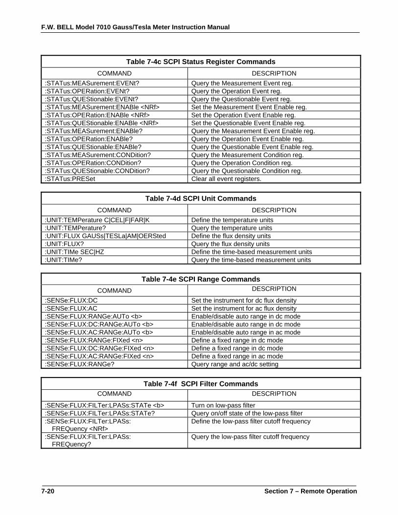
F.W. BELL Model 7010 Gauss/Tesla Meter Instruction Manual
7-20 Section 7 – Remote Operation
Table 7-4c SCPI Status Register Commands
COMMAND DESCRIPTION :STATus:MEASurement:EVENt? Query the Measurement Event reg. :STATus:OPERation:EVENt? Query the Operation Event reg. :STATus:QUEStionable:EVENt? Query the Questionable Event reg. :STATus:MEASurement:ENABle <NRf> Set the Measurement Event Enable reg. :STATus:OPERation:ENABle <NRf> Set the Operation Event Enable reg. :STATus:QUEStionable:ENABle <NRf> Set the Questionable Event Enable reg. :STATus:MEASurement:ENABle? Query the Measurement Event Enable reg. :STATus:OPERation:ENABle? Query the Operation Event Enable reg. :STATus:QUEStionable:ENABle? Query the Questionable Event Enable reg. :STATus:MEASurement:CONDition? Query the Measurement Condition reg. :STATus:OPERation:CONDition? Query the Operation Condition reg. :STATus:QUEStionable:CONDition? Query the Questionable Condition reg. :STATus:PRESet Clear all event registers.
Table 7-4d SCPI Unit Commands
COMMAND DESCRIPTION :UNIT:TEMPerature C|CEL|F|FAR|K Define the temperature units :UNIT:TEMPerature? Query the temperature units :UNIT:FLUX GAUSs|TESLa|AM|OERSted Define the flux density units :UNIT:FLUX? Query the flux density units :UNIT:TIMe SEC|HZ Define the time-based measurement units :UNIT:TIMe? Query the time-based measurement units
Table 7-4e SCPI Range Commands
COMMAND DESCRIPTION
:SENSe:FLUX:DC Set the instrument for dc flux density :SENSe:FLUX:AC Set the instrument for ac flux density :SENSe:FLUX:RANGe:AUTo <b> Enable/disable auto range in dc mode :SENSe:FLUX:DC:RANGe:AUTo <b> Enable/disable auto range in dc mode :SENSe:FLUX:AC:RANGe:AUTo <b> Enable/disable auto range in ac mode :SENSe:FLUX:RANGe:FIXed <n> Define a fixed range in dc mode :SENSe:FLUX:DC:RANGe:FIXed <n> Define a fixed range in dc mode :SENSe:FLUX:AC:RANGe:FIXed <n> Define a fixed range in ac mode :SENSe:FLUX:RANGe? Query range and ac/dc setting
Table 7-4f SCPI Filter Commands
COMMAND DESCRIPTION
:SENSe:FLUX:FILTer:LPASs:STATe <b> Turn on low-pass filter :SENSe:FLUX:FILTer:LPASs:STATe? Query on/off state of the low-pass filter :SENSe:FLUX:FILTer:LPASs: FREQuency <NRf>
Define the low-pass filter cutoff frequency
:SENSe:FLUX:FILTer:LPASs: FREQuency?
Query the low-pass filter cutoff frequency
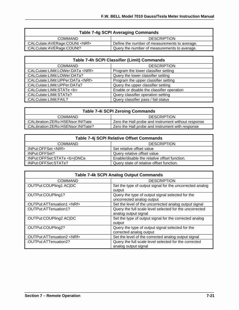
F.W. BELL Model 7010 Gauss/Tesla Meter Instruction Manual
Section 7 – Remote Operation 7-21
Table 7-4g SCPI Averaging Commands COMMAND DESCRIPTION
:CALCulate:AVERage:COUNt <NRf> Define the number of measurements to average. :CALCulate:AVERage:COUNt? Query the number of measurements to average.
Table 7-4h SCPI Classifier (Limit) Commands
COMMAND DESCRIPTION :CALCulate:LIMit:LOWer:DATa <NRf> Program the lower classifier setting :CALCulate:LIMit:LOWer:DATa? Query the lower classifier setting :CALCulate:LIMit:UPPer:DATa <NRf> Program the upper classifier setting :CALCulate:LIMit:UPPer:DATa? Query the upper classifier setting :CALCulate:LIMit:STATe <b> Enable or disable the classifier operation :CALCulate:LIMit:STATe? Query classifier operation setting :CALCulate:LIMit:FAIL? Query classifier pass / fail status
Table 7-4i SCPI Zeroing Commands
COMMAND DESCRIPTION :CALibration:ZERo:HSENsor:INITiate Zero the Hall probe and instrument without response :CALibration:ZERo:HSENsor:INITiate? Zero the Hall probe and instrument with response
Table 7-4j SCPI Relative Offset Commands
COMMAND DESCRIPTION :INPut:OFFSet <NRf> Set relative offset value :INPut:OFFSet? Query relative offset value :INPut:OFFSet:STATe <b>|ONCe Enable/disable the relative offset function. :INPut:OFFSet:STATe? Query state of relative offset function.
Table 7-4k SCPI Analog Output Commands
COMMAND DESCRIPTION :OUTPut:COUPling1 AC|DC Set the type of output signal for the uncorrected analog
output :OUTPut:COUPling1? Query the type of output signal selected for the
uncorrected analog output :OUTPut:ATTenuation1 <NRf> Set the level of the uncorrected analog output signal :OUTPut:ATTenuation1? Query the full scale level selected for the uncorrected
analog output signal :OUTPut:COUPling2 AC|DC Set the type of output signal for the corrected analog
output :OUTPut:COUPling2? Query the type of output signal selected for the
corrected analog output :OUTPut:ATTenuation2 <NRf> Set the level of the corrected analog output signal :OUTPut:ATTenuation2? Query the full scale level selected for the corrected
analog output signal
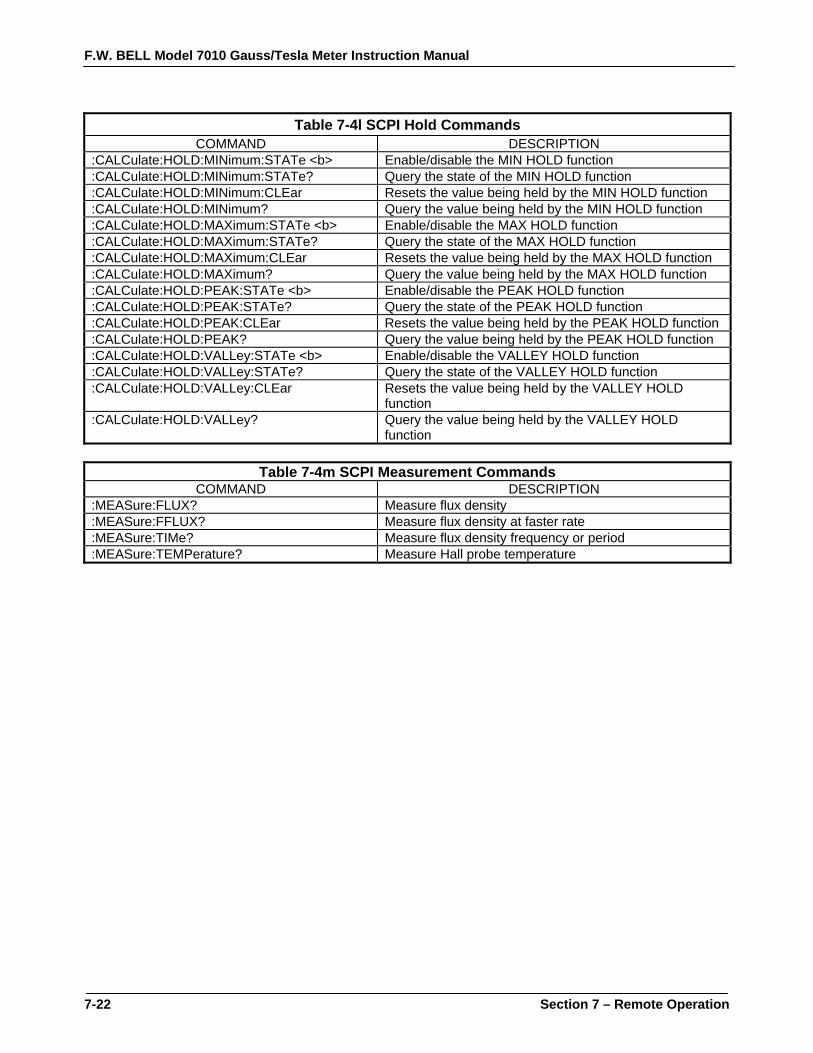
F.W. BELL Model 7010 Gauss/Tesla Meter Instruction Manual
7-22 Section 7 – Remote Operation
Table 7-4l SCPI Hold Commands
COMMAND DESCRIPTION :CALCulate:HOLD:MINimum:STATe <b> Enable/disable the MIN HOLD function :CALCulate:HOLD:MINimum:STATe? Query the state of the MIN HOLD function :CALCulate:HOLD:MINimum:CLEar Resets the value being held by the MIN HOLD function :CALCulate:HOLD:MINimum? Query the value being held by the MIN HOLD function :CALCulate:HOLD:MAXimum:STATe <b> Enable/disable the MAX HOLD function :CALCulate:HOLD:MAXimum:STATe? Query the state of the MAX HOLD function :CALCulate:HOLD:MAXimum:CLEar Resets the value being held by the MAX HOLD function :CALCulate:HOLD:MAXimum? Query the value being held by the MAX HOLD function :CALCulate:HOLD:PEAK:STATe <b> Enable/disable the PEAK HOLD function :CALCulate:HOLD:PEAK:STATe? Query the state of the PEAK HOLD function :CALCulate:HOLD:PEAK:CLEar Resets the value being held by the PEAK HOLD function :CALCulate:HOLD:PEAK? Query the value being held by the PEAK HOLD function :CALCulate:HOLD:VALLey:STATe <b> Enable/disable the VALLEY HOLD function :CALCulate:HOLD:VALLey:STATe? Query the state of the VALLEY HOLD function :CALCulate:HOLD:VALLey:CLEar Resets the value being held by the VALLEY HOLD
function :CALCulate:HOLD:VALLey? Query the value being held by the VALLEY HOLD
function
Table 7-4m SCPI Measurement Commands COMMAND DESCRIPTION
:MEASure:FLUX? Measure flux density :MEASure:FFLUX? Measure flux density at faster rate :MEASure:TIMe? Measure flux density frequency or period :MEASure:TEMPerature? Measure Hall probe temperature

F.W. BELL Model 7010 Gauss/Tesla Meter Instruction Manual
Section 7 – Remote Operation 7-23
SCPI COMMANDS- ERROR QUEUE MESSAGES AND COMMANDS
As error messages occur, they are placed in the error queue. Each message will contain a number, a comma (,) and a brief description of the error. Negative (-) numbers are used for SCPI defined messages while positive (+) numbers relate specifically to the instrument. The error queue can hold up to 10 messages. Each time the queue is read the oldest message is presented and removed from the queue. If no errors exist the message “0, No error” will be returned. If the queue is full the message “-350, Queue Overflow” will occupy the last queue location. It is an indication that at least one, perhaps more error message(s) were lost. There are certain error status bits that will set in the STANDARD EVENT register. These bits provide general error indications. The error queue will provide more detailed information about the errors. :SYSTem:ERRor? :SYSTem:ERRor:NEXT? This command places the oldest error message in the output queue and removes it from the error queue.
SCPI COMMANDS–SYSTEM INFORMATION AND CONFIGURATION COMMANDS
:SYSTem:VERSion? This command places the version number of the SCPI standard that is supported by this instrument in the output queue. The version number is in the format of “YYYY.V”, where “YYYY” is the year version of the standard and “V “is the approved revision number, such as “1999.0”. :SYSTem:TIMe <NRf>, <NRf>,<NRf> The instrument’s real time clock can be set from the DISPLAY menu or with this command using the following format:
:SYSTem:TIMe <hour>, <minute>, <second>
where: <hour> is in the range of 0 – 23 <minute> is in the range of 1 – 59 <second> is in the range of 1 – 59

F.W. BELL Model 7010 Gauss/Tesla Meter Instruction Manual
7-24 Section 7 – Remote Operation
SCPI COMMANDS –SYSTEM INFORMATION AND CONFIGURATION COMMANDS (Continued)
The clock supports 12-hour or 24-hour format. However, the format can only be set using the DISPLAY menu. The :SYSTem:TIMe command supports only a 24-hour format. If the clock has been set for 12-hour format <hours> will be converted internally to 12-hour format. For instance if <hours> is specified as 17 the time will be converted internally to 5 pm. Here is a simple conversion chart:
Table 7-5 12-hour to 24-hour Conversion
12-Hour Format 24- Hour Format 12- Hour Format 24- Hour Format 12 am 00 hours 12 pm 12 hours 1 am 01 hours 1 pm 13 hours 2 am 02 hours 2 pm 14 hours 3 am 03 hours 3 pm 15 hours 4 am 04 hours 4 pm 16 hours 5 am 05 hours 5 pm 17 hours 6 am 06 hours 6 pm 18 hours 7 am 07 hours 7 pm 19 hours 8 am 08 hours 8 pm 20 hours 9 am 09 hours 9 pm 21 hours 10 am 10 hours 10 pm 22 hours 11 am 11 hours 11 pm 23 hours
:SYSTem:TIMe?
The contents of the instrument’s real time clock will be returned using the following format: <hour>, <minute>, <second> where: <hour> is in the range of 0 – 23 (see below) <minute> is in the range of 1 – 59 <second> is in the range of 1 – 59 The clock supports 12-hour or 24-hour format. However, the format can only be set using the DISPLAY menu. The :SYSTem:TIMe? command supports only a 24-hour format. If the clock has been set for 12-hour format <hours> will be converted to 24-hour format. For instance if the present hours is 5 pm then <hours> will be returned as 17. See Table 7-5. :SYSTem:DATe <NRf>, <NRf>,<NRf> The instrument’s real time calendar can be set from the DISPLAY menu or with this command using the following format: :SYSTem:DATe <year>, <month>, <day> where: <year> is in the range of 2000 – 9999 <month> is in the range of 1–12 (1=January, 2=February, etc) <day> is in the range of 1 – 31 (day of the month)

F.W. BELL Model 7010 Gauss/Tesla Meter Instruction Manual
Section 7 – Remote Operation 7-25
SCPI COMMANDS –SYSTEM INFORMATION AND CONFIGURATION COMMANDS (Continued)
A <year> less than 2000 will not be accepted because the instrument did not exist prior to the year 2000. The instrument does not check the validity of the day of the month. For instance, a date of February 31 will not generate an error. :SYSTem:DATe? The contents of the instrument’s real time calendar will be returned using the following format: <year>, <month>, <day> where: <year> is in the range of 2000 – 9999 <month> is in the range of 1 – 12 (1 = January, 2 = February, etc) <day> is in the range of 1 – 31 (day of the month) :SYSTem:AZERo<b> This command enables advanced ac zeroing when <b> is “1” or “ON”, or disables advanced ac zeroing when <b> is “0” or “OFF”. See Section 6 for more information about advanced ac zeroing. :SYSTem:AZERo? The on/off state of advanced ac zeroing is placed in the output queue. :INPut:STATe <b> This command activates the channel when <b> is “1” or “ON”, or deactivates the channel when <b> is “0” or “OFF”. :INPut:STATe? The on/off state of the channel (“OFF” or “ON”) is placed in the output queue. :DISPlay:ENABle <b> When <b> is “1” or “ON” the display will be present normal flux density and related information. When <b> is “0” or “OFF” the display will contain the phrase “Display turned off via comm port. The process of updating the display on a continuous basis takes time away from the measurement process. Turning the display off can increase the speed at which readings can be acquired from a communication port. :DISPlay:ENABle? The on/off state of the display (“OFF” or “ON”) is placed in the output queue.

F.W. BELL Model 7010 Gauss/Tesla Meter Instruction Manual
7-26 Section 7 – Remote Operation
SCPI COMMANDS-STATUS COMMANDS
The STATUS commands control and query the MEASUREMENT EVENT, OPERATION EVENT and QUESTIONABLE EVENT registers as well as the error queue. :STATus:MEASurement:EVENt? :STATus:OPERation:EVENt? :STATus:QUEStionable:EVENt? Reads the contents of the specified EVENT register and places it in the output queue, then clears the register contents. :STATus:MEASurement:ENABle <NRf> :STATus:OPERation:ENABle <NRf> :STATus:QUEStionable:ENABle <NRf> Programs the specified EVENT ENABLE register with the value <NRf>. <NRf> is an ASCII string representing an integer mask. For instance a value of 45 decimal is the same as binary 00101101, thus setting bits 5, 3, 2 and 0 in the enable register. :STATus:MEASurement:ENABle? :STATus:OPERation:ENABle? :STATus:QUEStionable:ENABle? Reads the contents of the specified EVENT ENABLE register and places it in the output queue. :STATus:MEASurement:CONDition? :STATus:OPERation:CONDition? :STATus:QUEStionable:CONDition? Reads the contents of the specified EVENT CONDITION register and places it in the output queue. The EVENT CONDITION register is a real-time register reflecting the state of the instrument at the time of the read. Some conditions could happen very quickly and could be missed by this query. It is often better to rely on the contents of the EVENT register since it latches the event until cleared by a specific command. :STATus:PRESet Clears the MEASUREMENT EVENT ENABLE, OPERATION EVENT ENABLE and QUESTIONABLE EVENT ENABLE registers.
F.W. BELL Model 7010 Gauss/Tesla Meter Instruction Manual
Section 7 – Remote Operation 7-27
SCPI COMMANDS-UNIT COMMANDS
These commands select the measurement units for temperature, flux density and time-based measurements. :UNIT:TEMPerature C|CEL|F|FAR|K Specifies that the temperature units are to be in Celsius (C or CEL), Fahrenheit (F or FAR) or Kelvin (K). :UNIT:TEMPerature? Places an ASCII string in the output queue representing the temperature units. The ASCII string will be CEL for Celsius, FAR for Fahrenheit or K for Kelvin. :UNIT:FLUX GAUSs|TESLa|AM|OERSted Specifies that the flux density units are to be in gauss (GAUSs), tesla (TESLa), amps per meter (AM) or oersted (OERSted). :UNIT:FLUX? Places an ASCII string in the output queue representing the flux density units. The ASCII string will be GAUSS, TESLA, AM or OERSTED. :UNIT:TIME SEC|HZ Specifies that the time-based measurement units are to be period measurements in seconds (SEC) or frequency measurements in hertz (HZ). :UNIT:TIME? Places an ASCII string in the output queue representing the time-based measurement units. The ASCII string will be SEC for period measurements or HZ for frequency measurements.

F.W. BELL Model 7010 Gauss/Tesla Meter Instruction Manual
7-28 Section 7 – Remote Operation
SCPI COMMANDS-RANGE COMMANDS
These commands select either a fixed range or AUTO range, and specify if the measured flux density will be static (dc) or alternating (ac). :SENSe:FLUX:AC :SENSe:FLUX:DC Specifies that the measured flux density will be static (dc) or alternating (ac). These commands do not alter the present range setting. :SENSe:FLUX:RANGe:FIXed <n> :SENSe:FLUX:DC:RANGe:FIXed <n> :SENSe:FLUX:AC:RANGe:FIXed <n> Specifies that the measured flux density will be static (dc) or alternating (ac). If the “AC” or “DC” key word is omitted, then static (dc) operation is selected. Also specifies one of four fixed operating ranges for the instrument, as defined in the following table:
Table 7-6 Operating Ranges with Various Probes
<n>
Maximum Flux Density Using Low Field Probe
Maximum Flux Density Using Mid Field Probe
Maximum Flux Density Using High Field Probe
1 300 mG (30 µT) 30 G (3 mT) 300 G (30 mT) 2 3 G (300 µT) 300 G (30 mT) 3 kG (300 mT) 3 30 G (3 mT) 3 kG (300 mT) 30 kG (3 T) 4 300 G (30 mT) 30 kG (3 T) 300 kG (30 T)
:SENSe:FLUX:RANGe:AUTo <b>
:SENSe:FLUX:DC:RANGe:AUTo <b> :SENSe:FLUX:AC:RANGe:AUTo <b> Specifies that the measured flux density will be static (dc) or alternating (ac). If the “AC” or “DC” key word is omitted, then static (dc) operation is selected. AUTO ranging is turned off when <b> is “0” or “OFF”, or on when <b> is “1” or “ON”. When AUTO range is turned on the instrument determines the range that will offer the best resolution. When AUTOrange is turned off the range will be fixed to the last range that was in use when the command was issued.
F.W. BELL Model 7010 Gauss/Tesla Meter Instruction Manual
Section 7 – Remote Operation 7-29
SCPI COMMANDS-RANGE COMMANDS (Continued)
:SENSe:FLUX:RANGe? Places an ASCII string in the output queue representing the present ac/dc setting, the present range and the state of the AUTO range feature. The string will start with the phrase “AC” or “DC, followed by a comma(,). The next single digit will be the range setting, as shown in Table 7-6, and will be in the range of 1 to 4, followed by a comma(,). Next will be the phrase “OFF” or “ON, indicating the state of the AUTO range feature. For example the string DC,2,OFF indicates that the channel is in dc mode on a fixed range setting of 2.
SCPI COMMANDS-FILTER COMMANDS
These commands control the hardware low-pass filters. :SENSe:FLUX:FILTer:LPASs:FREQuency <NRf> There are two choices for the cutoff frequency for the low pass filter; 500 Hz or 5 kHz. These are two-pole filters with an attenuation of –12 db per octave. <NRf> specifies the cutoff frequency in hertz, either 500 or 5000. :SENSe:FLUX:FILTer:LPASs:FREQuency? Places the low-pass filter’s cutoff frequency in hertz in the output queue, either 500 or 5000. :SENSe:FLUX:FILTer:LPASs:STATe <b>|AUTo The low-pass filter is turned off when <b> is “0” or “OFF”, on when <b> is “1” or “ON”, or placed in AUTO mode then <b> is “AUTo”. When the low pass filter is turned off, the instrument has an inherent cutoff of 50kHz. :SENSe:FLUX:FILTer:LPASs:STATe? The state of the low-pass filter (”OFF”, “ON” or “AUTO”) is placed in the output queue.
F.W. BELL Model 7010 Gauss/Tesla Meter Instruction Manual
7-30 Section 7 – Remote Operation
SCPI COMMANDS-AVERAGING COMMANDS
These commands control the software averaging. :CALCulate:AVERage:COUNt <NRf> A new measurement is acquired approximately every 0.032 seconds. The system requires a minimum of 6 measurements to be averaged, which results in a new flux density reading every 0.2 seconds. For greater stability the number of measurements to average can be increased to 15, 30 or 60, resulting in new flux density readings every 0.5, 1 or 2 seconds, respectively. Thus, <NRf> can be 6 (0.2 second update rate)
15 (0.5 second update rate) 30 (1.0 second update rate) 60 (2.0 second update rate)
:CALCulate:AVERage:COUNt? A new measurement is acquired approximately every 0.032 seconds. The system requires a minimum of 6 measurements to be averaged, which results in a new flux density reading every 0.2 seconds. For greater stability the number of measurements to average can be increased to 15, 30 or 60, resulting in new flux density readings every 0.5, 1 or 2 seconds, respectively. This command returns the number of measurements being used for the average, either “6”, “15”, “30” or “60”.
SCPI COMMANDS- CLASSIFIER (LIMIT) COMMANDS
These commands control the CLASSIFIER, or limit checking function. Two individual flux density limits can be specified. If the present flux density reading becomes arithmetically less than the lower limit, or arithmetically greater than the upper limit, the situation is considered to be a “failure”.

F.W. BELL Model 7010 Gauss/Tesla Meter Instruction Manual
Section 7 – Remote Operation 7-31
SCPI COMMANDS- CLASSIFIER (LIMIT) COMMANDS (Continued)
:CALCulate:LIMit:LOWer:DATa <NRf> :CALCulate:LIMit:UPPer:DATa <NRf> <NRf> is a signed decimal number that sets the lower and upper classifier limits. <NRf> must be between 0.0000000000 and ± 29999999. The meaning of the limit depends upon the currently selected unit of measure (gauss, tesla, etc.). For instance the value 1.0203 could mean 1.0203 G or 1.0203 T. If a lower limit is specified that is arithmetically larger than the upper limit, the two limits will be reversed internally. The sign of the limit has no meaning in the ac measurement mode. :CALCulate:LIMit:LOWer:DATa? :CALCulate:LIMit:UPPer:DATa? The requested classifier limit is placed in the output queue. The limit will be between 0.0000000000 and ± 29999999. The meaning of the limit depends upon the currently selected unit of measure (gauss, tesla, etc.). For instance the value 1.0203 could mean 1.0203 G or 1.0203 T. :CALCulate:LIMit:STATe <b> The classifier function is turned on when <b> is “1” or “ON”, or turned off when <b> is “0“ or “OFF”. :CALCulate:LIMit:STATe? The state of the classifier function (“OFF” or “ON”) is placed in the output queue. :CALCulate:LIMit:FAIL? The pass/fail status of the classifier test is placed in the output queue. A “0” indicates that the measured value falls between the lower and upper limit and is considered a “pass” situation. A “1” indicates that the measured value either falls below the lower limit or above the higher limit.
F.W. BELL Model 7010 Gauss/Tesla Meter Instruction Manual
7-32 Section 7 – Remote Operation
SCPI COMMANDS-ZEROING COMMANDS
These commands control zeroing of the Hall probe and the instrument. :CALibration:ZERo:HSENsor:INITiate This command initiates the same zeroing process as the front-panel ZERO push button. The Hall probe should be placed in a stable, low-flux environment such as a zero flux chamber prior to issuing this command. While zeroing is in progress the “ZERO” status bit in the OPERATION CONDITION REGISTER will be set. This command does not generate a response. :CALibration:ZERo:HSENsor:INITiate? Same as the “:CALibration:ZERo:HSENsor:INITiate” command, but a response is returned upon completion of the zeroing process. A “0” indicates successful completion, otherwise a non-zero number is returned indicating a failure.
SCPI COMMANDS-RELATIVE OFFSET COMMANDS
These commands control the RELATIVE function. The RELATIVE function subtracts a fixed flux density value from all measured values. The user can define the offset or it can be generated using the present value of flux density as measured by the Hall probe. There are some limitations when using the RELATIVE function. Refer to Section 6 - Flux Density Measurement for details.

F.W. BELL Model 7010 Gauss/Tesla Meter Instruction Manual
Section 7 – Remote Operation 7-33
SCPI COMMANDS-RELATIVE OFFSET COMMANDS (Continued)
:INPut:OFFSet <NRf> This command defines a fixed relative offset value, which will be subtracted from all measured values. The relative offset value will only be used when the RELATIVE function is enabled. See the “:INPut:OFFSet:STATe” command for details. <NRf> is a signed decimal number between 0.0000000000 and ± 29999999. The meaning of the offset depends upon the currently selected unit of measure (gauss, tesla, etc.). For instance the value 1.0203 could mean 1.0203 G or 1.0203 T. :INPut:OFFSet? The relative offset value is placed in the output queue and will be between 0.0000000000 and ± 29999999. The meaning of the offset depends upon the currently selected unit of measure (gauss, tesla, etc.). For instance the value 1.0203 could mean 1.0203 G or 1.0203 T. :INPut:OFFSet:STATe <b>|ONCe When <b> is “0” or “OFF” the RELATIVE function is turned off. The present flux density readings will not be altered. The previously defined relative offset value will be preserved. When <b> is “1” or “ON” the RELATIVE function will be enabled. A fixed relative offset value will be subtracted from all flux density readings. This value could have been previously defined using the “:INPut:OFFSet <NRf>” command, manually entered using the RELATIVE menu, or generated automatically using the probe as the input source. When <b> is “ONCe” the automatic RELATIVE operation is started. This command initiates the same process as the front-panel RELATIVE push button. The Hall probe should be placed in a stable environment prior to issuing this command. The value presently measured by the probe will become the new relative offset value. This will overwrite any value previously defined using the “:INPut:OFFSet <NRf>” command or entered manually from the RELATIVE menu. When the automatic RELATIVE operation is complete the RELATIVE function will be enabled. :INPut:OFFSet:STATe? The state of the RELATIVE function (“OFF” or “ON”) is placed in the output queue.

F.W. BELL Model 7010 Gauss/Tesla Meter Instruction Manual
7-34 Section 7 – Remote Operation
SCPI COMMANDS-ANALOG OUTPUT COMMANDS
The instrument provides an uncorrected analog output signal that originates from the amplifier section. This signal is not corrected for errors in the Hall probe or instrument but is capable of high frequency operation. Also provided is a corrected output signal that is generated digitally. This signal is corrected for most errors in the Hall probe and instrument, but is only capable of low-frequency reproduction. You can define the type of signal that appears at each output and the scale of that signal, from the ANALOG OUT menu or by issuing these commands :OUTPut:COUPling1 AC|DC When the channel is configured for alternating (ac) flux density measurement you can select one of two signals to appear at the uncorrected analog output. When “AC” is specified the signal will be the real-time waveform as measured by the Hall probe. When “DC” is specified the output signal will be a dc level representing the true rms value of the waveform. When the channel is configured for static (dc) flux density measurement you can select one of two signals to appear at the uncorrected analog output. When “AC” is specified the signal will be the real-time, low frequency waveform as measured by the Hall probe, from 0 – 400 Hz. When “DC” is specified the output signal will be a dc level representing the true rms value of the low frequency waveform. :OUTPut:COUPling1? The type of signal selected for the uncorrected analog output (“AC” or “DC”) is placed in the output queue. :OUTPut:ATTenuation1 <NRf> The full scale output voltage of the uncorrected analog output can be specified to any level between 0 and 10 volts in 0.1 volt steps. Normally a full-scale level of 3.0 volts is used because it directly corresponds to the full-scale ranges of the instrument. For instance, if on the 300 mT range, a reading of -189.3 mT will result in an analog output of -1.893 volts. If on the 3 kG range, a reading of +2.6 kG will result in an analog output of +2.6 volts.

F.W. BELL Model 7010 Gauss/Tesla Meter Instruction Manual
Section 7 – Remote Operation 7-35
SCPI COMMANDS-ANALOG OUTPUT COMMANDS (Continued)
Some data acquisition systems may require different analog input ranges. For example, assume such a system cannot accept signals greater than ± 2.0 volts. In this case you can specify 2.0V as the full-scale range of the analog output (<NRf> = 2.0). The relationship between the output voltage and the flux density reading is: Full scale output voltage / full scale flux density range
For example, assume the full scale output voltage has been set to 2.0 volts and the present range setting is 300 mT. The relationship will be: 2.0 volts / 300 mT = 0.0067 volts / mT Thus, when the flux density reaches the maximum for the present range, the analog output voltage will reach a maximum of ± 2.0 volts. :OUTPut:ATTenuation1? The full scale voltage setting of the uncorrected analog output (0.0 to 10.0) is placed in the output queue. :OUTPut:COUPling2 AC|DC When the instrument is configured for alternating (ac) flux density measurement you can select one of two signals to appear at the corrected analog output. When “AC” is specified the signal will be the real-time waveform as measured by the Hall probe, within the low frequency limits of the corrected output. When “DC” is specified the output signal will be a dc level representing the true rms value of the low frequency waveform. When the instrument is configured for static (dc) flux density measurement you can select one of two signals to appear at the corrected analog output. When “AC” is specified the signal will be the real-time, low frequency waveform as measured by the Hall probe, within the low frequency limits of the corrected output. When “DC” is specified the output signal will be a dc level representing the true rms value of the low frequency waveform.
F.W. BELL Model 7010 Gauss/Tesla Meter Instruction Manual
7-36 Section 7 – Remote Operation
SCPI COMMANDS-ANALOG OUTPUT COMMANDS (Continued)
:OUTPut:COUPling2? The type of signal selected for the corrected analog output (“AC” or “DC”) is placed in the output queue. :OUTPut:ATTenuation2 <NRf> The full scale output voltage of the corrected analog output can be specified to any level between 0 and 10 volts in 0.1 volt steps. Normally a full-scale level of 3.0 volts is used because it directly corresponds to the full-scale ranges of the instrument. For instance, if on the 300 mT range, a reading of -189.3 mT will result in an analog output of -1.893 volts. If on the 3 kG range, a reading of +2.6 kG will result in an analog output of +2.6 volts. Some data acquisition systems may require different analog input ranges. For example, assume such a system cannot accept signals greater than ± 2.0 volts. In this case you can specify 2.0V as the full-scale range of the analog output (<NRf> = 2.0). The relationship between the output voltage and the flux density reading is:
Full scale output voltage / full scale flux density range
For example, assume the full scale output voltage has been set to 2.0 volts and the present range setting is 300 mT. The relationship will be: 2.0 volts / 300 mT = 0.0067 volts / mT Thus, when the flux density reaches the maximum for the present range, the analog output voltage will reach a maximum of ± 2.0 volts. :OUTPut:ATTenuation2? The full scale voltage setting of the corrected analog output (0.0 to 10.0) is placed in the output queue.

F.W. BELL Model 7010 Gauss/Tesla Meter Instruction Manual
Section 7 – Remote Operation 7-37
SCPI COMMANDS- HOLD COMMANDS
:CALCulate:HOLD:MINimum:STATe <b> The MIN HOLD function is turned on when <b> is “1” or “ON”, or turned off when <b> is “0“ or “OFF”. :CALCulate:HOLD:MINimum:STATe? The state of the MIN HOLD function (“OFF” or “ON”) is placed in the output queue. :CALCulate:HOLD:MINimum:CLEar The value being held by the MIN HOLD function is reset to 0. :CALCulate:HOLD:MINimum? The value being held by the MIN HOLD function is placed in the output queue and will be between 0.0000000000 and ± 29999999. The meaning of this value depends upon the currently selected unit of measure (gauss, tesla, etc.). For instance the value 1.0203 could mean 1.0203 G or 1.0203 T.
:CALCulate:HOLD:MAXimum:STATe <b> The MAX HOLD function is turned on when <b> is “1” or “ON”, or turned off when <b> is “0“ or “OFF”. :CALCulate:HOLD:MAXimum:STATe? The state of the MAX HOLD function (“OFF” or “ON”) is placed in the output queue. :CALCulate:HOLD:MAXimum:CLEar The value being held by the MAX HOLD function is reset to 0. :CALCulate:HOLD:MAXimum? The value being held by the MAX HOLD function is placed in the output queue and will be between 0.0000000000 and ± 29999999. The meaning of this value depends upon the currently selected unit of measure (gauss, tesla, etc.). For instance the value 1.0203 could mean 1.0203 G or 1.0203 T.

F.W. BELL Model 7010 Gauss/Tesla Meter Instruction Manual
7-38 Section 7 – Remote Operation
SCPI COMMANDS- HOLD COMMANDS (Continued)
:CALCulate:HOLD:PEAK:STATe <b> The PEAK HOLD function is turned on when <b> is “1” or “ON”, or turned off when <b> is “0“ or “OFF”. :CALCulate:HOLD:PEAK:STATe? The state of the PEAK HOLD function (“OFF” or “ON”) is placed in the output queue. :CALCulate:HOLD:PEAK:CLEar The value being held by the PEAK HOLD function is reset to 0. :CALCulate:HOLD:PEAK? The value being held by the PEAK HOLD function is placed in the output queue and will be between 0.0000000000 and ± 29999999. The meaning of this value depends upon the currently selected unit of measure (gauss, tesla, etc.). For instance the value 1.0203 could mean 1.0203 G or 1.0203 T. :CALCulate:HOLD:VALLey:STATe <b> The VALLEY HOLD function is turned on when <b> is “1” or “ON”, or turned off when <b> is “0“ or “OFF”. :CALCulate:HOLD:VALLey:STATe? The state of the VALLEY HOLD function (“OFF” or “ON”) is placed in the output queue. :CALCulate:HOLD:VALLey:CLEar The value being held by the VALLEY HOLD function is reset to 0. :CALCulate:HOLD:VALLey? The value being held by the VALLEY HOLD function is placed in the output queue and will be between 0.0000000000 and ± 29999999. The meaning of this value depends upon the currently selected unit of measure (gauss, tesla, etc.). For instance the value -1.0203 could mean -1.0203 G or -1.0203 T.

F.W. BELL Model 7010 Gauss/Tesla Meter Instruction Manual
Section 7 – Remote Operation 7-39
SCPI COMMANDS-MEASUREMENT COMMANDS
:MEASure:FLUX? The latest flux density reading is placed in the output queue and will be between 0.0000000000 and ± 29999999. The meaning of this value depends upon the currently selected unit of measure (gauss, tesla, etc.). For instance the value 1.0203 could mean 1.0203 G or 1.0203 T. The rate at which flux density readings are updated is specified in the FILTER menu (or by using the CALCulate:AVERage:COUNt command). Issuing the MEASure:FLUX? command at a rate that is faster than this update rate will return the same reading multiple times. For instance, if the meter updates the reading once per second, and the MEASure:FLUX? command is issued 10 times per second, the same reading will be returned 10 times. To avoid this the Reading Available (RAV) status bit in the Measurement Event Register can be monitored to determine when a new reading is available. :MEASure:FFLux? This command is similar to the MEASure:FLUX? command but can be used to acquire new flux density readings at a much faster rate. However, the returned values may not be as precise or accurate. For example, if the presently displayed reading is 2.87347 T, this command may return 2.872 T. This command uses the same information that is used to construct the corrected analog output, therefore the accuracy is the same as specified for the corrected analog output. The corrected analog output must be turned on to use this command. Use the ANALOG OUT menu or OUTPut commands to enable the output. The analog output voltage range has no affect on the returned value, so it can be set to any desired level. However, the type of output selected, whether “raw” or “rms”, will affect the value returned by this command. For example assume that the probe is measuring a 50 Hz sinusoidal field with an rms value of 2.5 gauss. If the corrected analog output is configured for “rms” then the returned value will be 2.5. If the output is configured for “raw” then the value returned will be one point of the 50 Hz waveform, which can range from 0 to ± 3.535 gauss (the peak value of a 2.5 gauss rms signal is about 3.535 gauss).

F.W. BELL Model 7010 Gauss/Tesla Meter Instruction Manual
7-40 Section 7 – Remote Operation
SCPI COMMANDS-MEASUREMENT COMMANDS (Continued)
The rate at which new flux density readings can be acquired using this command is roughly 100 per second, but the speed of the communications port can degrade this. For example, suppose the abbreviated version of the command is issued, such as “MEAS:FFL?<lf>. If the RS-232 port is used at a baud rate of 9600, a character length of 7, one stop bit and no parity, it would take at minimum about 0.011 seconds to transmit the command. If the meter returns a value of “–22.34;<lf>”, this would take about 0.008 seconds. There is also a small amount of time needed for the meter to interpret the command and acquire a reading. So, let’s assume a total of 0.02 seconds for one transaction. This would limit the number of readings to 50 per second, best case. Use a higher baud rate or the GPIB interface to increase the speed. :MEASure:TEMPerature? The latest temperature reading from a temperature-compensated Hall probe is placed in the output queue. The meaning of this value depends upon the currently selected unit of measure (celsius, kelvin or fahrenheit). For instance the value 45.3 could mean 45.3 °F or 45.3 °C. :MEASure:TIMe? The latest frequency or period measurement of the flux density signal is placed in the output queue. The meaning of this value depends upon the currently selected unit of measure (seconds or hertz).
INTERMIXING “COMMON” AND SCPI COMMANDS
As mentioned earlier a string sent to the instrument can contain more than one command as long as the commands are separated by semicolons(;). “Common” and SCPI commands can be intermixed.

F.W. BELL Model 7010 Gauss/Tesla Meter Instruction Manual
Section 7 – Remote Operation 7-41
MESSAGE TERMINATORS
When transmitting a string to the instrument the message must be “terminated” properly to notify the instrument that the message is complete. One way is to append an ASCII line feed (LF) character as the final character in the string, which is a 0A hex or 00001010 binary. Note that 0A hex is equivalent to 10 decimal, but sending the two ASCII characters “10” will not work. It must be the single byte representation of the LF control character. If using the IEEE-488 bus the second way to terminate a message is to assert the End-or-Identify (EOI) bus line at the same time the final character is sent to the instrument. It is also acceptable to send the LF character and assert EOI with that character. In most cases sending the LF character and/or asserting the EOI line is a function of the IEEE-488 controller card being used, and can be specified when the card’s configuration program is run. Usually the user has the option to automatically append the LF character and/or assert the EOI line with every transmission to the instrument. If not it is the programmer’s task to append the LF character to each string and/or make sure the EOI line is asserted with the last character transmitted. When using the RS-232 port the instrument will always send the LF character every time it transmits a message to the system controller. When using the IEEE-488 bus the instrument will send the LF character and assert the EOI line every time it transmits a message to the system controller.
F.W. BELL Model 7010 Gauss/Tesla Meter Instruction Manual
7-42 Section 7 – Remote Operation
EXAMPLE: USING THE EVENT, ENABLE, AND CONDITION REGISTERS
If you are overwhelmed by the use of the EVENT, CONDITION and ENABLE registers, this example should help. The goal is to get the attention of the computer when a reading is available from the instrument. This means we have to assert the SRQ interface line on the GPIB bus, or set some status condition that can be read via the RS-232 port.
The “RQS” bit in the STATUS BYTE directly affects the SRQ interface line.
When it becomes “1” the line is asserted. “RQS” can be affected by six conditions, four of which are controlled by event registers. In one of these, the MEASUREMENT EVENT register, there is a bit called “RAV”, which sets to “1” when a reading is available. So, when “RAV” goes to “1” we want “RQS” to go to “1”. 1) To allow the “RAV” event to reach the STATUS BYTE we must set the
corresponding bit in the MEASUREMENT ENABLE register. “RAV” is bit location D4. The decimal value that will set bit location D4 is 16. The SCPI command is
:STATUS:MEASUREMENT:ENABLE 16 2) The “RAV” event will now set the “MSB” (Measurement Summary Bit) in
the STATUS BYTE. But this will not set the “RQS” bit unless the “MSB” event is enabled in the SRQ ENABLE register. “MSB” is bit location D0. The decimal value that will set bit location D0 is 1. The “common” command is
*SRE 1 Now as soon as a reading is available the “RQS” bit will set and the SRQ interface line will be asserted. For GPIB users the system controller, not knowing which instrument is requesting service, will sequentially read each instrument’s serial poll register to determine who is asserting SRQ. For RS-232 users there is no dedicated interface line that can be used to get the attention of the computer. However, the STATUS BYTE can be inspected from time to time to determine when an event has occurred. This is done using the *STB? Command. Normally the STATUS BYTE would be read first to determine the general cause for the request, then the EVENT register would be read to determine the exact nature of the request. The latter step is very important because the act of reading the EVENT register is what clears the event. Simply reading the STATUS BYTE or asking for a flux density reading will not reset the “RAV” bit. You must read the MEASUREMENT EVENT register to reset “RAV”. The SCPI command is :STATUS:MEASUREMENT:EVENT?

F.W. BELL Model 7010 Gauss/Tesla Meter Instruction Manual
Appendix A – Understanding Flux Density A-1
Appendix A Understanding Flux Density Magnetic fields surrounding permanent magnets or electrical conductors can be visualized as a collection of magnetic flux lines; lines of force existing in the material that is being subjected to a magnetizing influence. Unlike light, which travels away from its source indefinitely, magnetic flux lines must eventually return to the source. Thus all magnetic sources are said to have two poles. Flux lines are said to emanate from the “north” pole and return to the “south” pole, as depicted in Figure A-1.
Figure A-1 Flux Lines of a Permanent Magnet One line of flux in the cgs measurement system is called a maxwell (Mx), but the weber (Wb), which is 108 lines, is more commonly used. Flux density, also called magnetic induction, is the number of flux lines passing through a given area. It is commonly assigned the symbol “B” in scientific documents. In the cgs system a gauss (G) is one line of flux passing through a 1 cm2 area. The more commonly used term is the tesla (T), which is 10,000 lines per cm2 . Thus 1 tesla = 10,000 gauss 1 gauss = 0.0001 tesla Magnetic field strength is a measure of force produced by an electric current or a permanent magnet. It is the ability to induce a magnetic field “B”. It is commonly assigned the symbol “H” in scientific documents. The unit of “H” in the cgs system is an oersted (Oe), but the ampere/meter (A/m) is more commonly used. The relationship is 1 oersted = 79.6 ampere/meter 1 ampere/meter = 0.01256 oersted It is important to know that magnetic field strength and magnetic flux density are not the same. The only time the two are considered equal is in free space. Only in free space is the following relationship true: 1 G = 1 Oe = 0.0001 T = 79.6 A/m

F.W. BELL Model 7010 Gauss/Tesla Meter Instruction Manual
A-2 Appendix A – Understanding Flux Density
MEASUREMENT OF FLUX DENSITY: A device commonly used to measure flux density is the Hall effect sensor. A Hall effect sensor is a thin slice of a semiconductor material to which four leads are attached at the midpoint of each edge, as shown in Figure A-2. Hall Effect Sensor Figure A-2 Hall Effect Sensor A constant current (Ic) is forced through the material. In a zero magnetic field there is no voltage difference between the other two edges. When flux lines pass through the material the path of the current bends closer to one edge, creating a voltage difference known as the Hall voltage (Vh). In an ideal Hall generator there is a linear relationship between the number of flux lines passing through the material (flux density) and the Hall voltage. The Hall voltage is also a function of the direction in which the flux lines pass through the material, producing a positive voltage in one direction and a negative voltage in the other. If the same number of flux lines pass through the material in either direction, the net result is zero volts. This sensitivity to flux direction makes it possible to measure both static (dc) and alternating (ac) magnetic fields. The Hall voltage is also a function of the angle at which the flux lines pass through the material. The greatest Hall voltage occurs when the flux lines pass perpendicularly through the material. Otherwise the output is related to the cosine of the difference between 90° and the actual angle. The sensitive area of the Hall effect sensor is generally defined as the largest circular area within the actual slice of the material. This active area can range in size from 0.2 mm (0.008”) to 19 mm (0.75”) in diameter. Often the Hall effect sensor assembly is too fragile to use by itself so it is often mounted in a protective tube and terminated with a flexible cable and a connector. This assembly is known as a Hall probe. For more information on Hall Probes see Section 3 – Probes.

F.W. BELL Model 7010 Gauss/Tesla Meter Instruction Manual
Appendix A – Understanding Flux Density A-3
This Page Intentionally Blank

WARRANTY
This instrument is warranted to be free of defects in material and workmanship. OECO, LLC’s (hereafter OECO) obligation under this warranty is limited to servicing or adjusting any instrument returned to the factory for that purpose, and to replace any defective parts thereof. This warranty covers instruments which, within one year after delivery to the original purchaser, shall be returned with transportation charges prepaid by the original purchaser, and which upon examination shall disclose to OECO’s satisfaction to be defective. If it is determined that the defect has been caused by misuse or abnormal conditions of operation, repairs will be billed at cost after submitting an estimate to the purchaser. OECO reserves the right to make changes in design at any time without incurring any obligation to install same on units previously purchased. THE ABOVE WARRANTY IS EXPRESSLY IN LIEU OF ALL OTHER WARRANTIES EXPRESSED OR IMPLIED AND ALL OTHER OBLIGATIONS AND LIABILITIES ON THE PART OF OECO, AND NO PERSON INCLUDING ANY DISTRIBUTOR, AGENT OR REPRESENTATIVE OF OECO IS AUTHORIZED TO ASSUME FOR OECO ANY LIABILITY ON ITS BEHALF OR ITS NAME, EXCEPT TO REFER THE PURCHASER TO THIS WARRANTY. THE ABOVE EXPRESS WARRANTY IS THE ONLY WARRANTY MADE BY OECO. OECO DOES NOT MAKE AND EXPRESSLY DISCLAIMS ANY OTHER WARRANTIES, EITHER EXPRESSED OR IMPLIED, INCLUDING WITHOUT LIMITING THE FOREGOING, WARRANTIES OF MERCHANTABILITY OR FITNESS FOR A PARTICULAR PURPOSE OR ARISING BY STATUE OR OTHERWISE IN LAW OR FROM A COURSE OF DEALING OR USAGE OR TRADE. THE EXPRESS WARRANTY STATED ABOVE IS MADE IN LIEU OF ALL LIABILITIES FOR DAMAGES, INCLUDING BUT NOT LIMITED TO CONSEQUENTIAL DAMAGES, LOST PROFITS OR THE LIKE ARISING OUT OF OR IN CONNECTION WITH THE SALE, DELIVERY, USE OR PERFORMANCE OF THE GOODS. IN NO EVENT WILL OECO BE LIABLE FOR SPECIAL, INDIRECT OR CONSEQUENTIAL DAMAGES EVEN IF OECO HAS BEEN ADVISED OF THE POSSIBILITY OF SUCH DAMAGES. This warranty gives you specific legal rights, and you may also have other rights that vary from state to state.

THIS SIDE BLANK ! (Front of Rear Cover)

4607 SE International Way Milwaukie, OR 97222 Phone: 503-659-5999
www.oeco.com