5400 / 6400 - voremarketingco | just another … – 50 5400/6400 wiring 51 limited warranty ....
TRANSCRIPT

5400 / 6400
www.heartlandtan.com Part# 54066

Table of Contents
1 WARNINGS AND CAUTIONS 2 MANDATORY READING 3 SKIN GUIDE
4 - 5 5400 SPECIFICATIONS AND REQUIREMENTS 6 - 7 5400 EXPOSURE SCHEDULE 8 - 9 6400 SPECIFICATIONS AND REQUIREMENTS
10 -11 6400 EXPOSURE SCHEDULE 12 REPAIRS, SERVICE, REPLACEMENT PARTS, LAMPS, AND EYE PROTECTION 13 CARE AND CLEANING 14 LAMP GUIDE 15 RELAMPING INSTRUCTIONS 15 REPLACING LOW-PRESSURE LAMPS 16 REPLACING HIGH-PRESSURE FACIAL LAMPS 17 REPLACING HIGH-PRESSURE SHOULDER TANNER LAMPS
18 – 26 5400/6400 TIMER GUIDE 27 5400/6400 AUDIO SYSTEM
28 – 34 5400 INSTALLATION INSTRUCTIONS 35 – 42 6400 INSTALLATION INSTRUCTIONS 43 – 50 5400/6400 WIRING
51 LIMITED WARRANTY

WELCOME Dear Valued Customer: Congratulations! You have just purchased one of the finest pieces of tanning equipment available to the indoor tanning industry. We at Heartland Tanning, Inc. sincerely appreciate your business. The OVATION™ line is manufactured right here in the heart of our country. Our tanning equipment is constructed and designed to hold up under heavy use. We have confidence in our manufactured products and that is why our equipment is backed by Heartland’s unprecedented 5 year limited warranty. Designed to be user friendly, the OVATION™ line tanning beds are easy to assemble and maintain. Please read your owner & assembly manual thoroughly prior to the first use of your new tanning unit. Heartland Tanning, Inc. 4251 N.E. Port Drive Lee’s Summit, MO 64064
1-800-554-8268 NOTICE: Any misuse, abuse, modifications, alteration, improper installation, etc. of this product or its intended use will subject said party to direct responsibility for any and all consequences resulting from such action. Furthermore, such actions will void all warranties and may relieve Heartland Tanning, Inc. of any liabilities relating to said product.

WARNINGS AND CAUTIONS Certain drugs, particularly those designed to produce photosensitivity, may cause individuals under the influence of these types of drugs to experience adverse effects and those people should avoid exposure to UV sources of all types. Doctors will advise persons taking these drugs of possible adverse effects. It is recommended that only one (1) person at a time use this tanning system, and we advise wearing protective eyewear while using the tanning unit. Two (2) pair of protective eyewear are provided with each bed sold.
WARNING If you have been diagnosed by a physician as being allergic to the sun or are currently taking photosensitive medications, consult your physician before using the tanning unit.
CAUTION While there is no immediate clinical evidence regarding UVA exposure and its effects upon expectant mothers, it is strongly advised that expectant mothers be discouraged from using the tanning unit.
www.heartlandtan.com 1 12/06

MANDATORY READING
ALWAYS FOLLOW INSTRUCTIONS FOR PROPER USAGE PRIOR TO USING ANY TANNING SYSTEM.
REMEMBER
1. Follow the exposure schedule in accordance with your skin type. Failure to do so may result in overexposure.
2. Replacement lamps must comply with CFR 21 1040.20. When ordering
lamps, include model number and serial number. See Lamp Guide for the appropriate lamp replacements for your Tanning Bed.
Should you have any questions regarding the proper use of your tanning system, please contact:
Heartland Tanning, Inc. 1-800-554-8268 8:00AM to 5:00PM (CST)
www.heartlandtan.com 2 12/06

SKIN GUIDE MELANIN - The brownish pigment produced by special cells in the base layer of the skin determines the individual’s tan. As the skin is exposed to the ultraviolet light, the melanin is activated and combines with protein cells that rise to the skin’s surface, thus producing a tan. The amount of melanin in your body determines how quickly and dark you tan. The more melanin produced and exposure time an individual has, the faster and deeper the individual will tan. NOTE The tan produced by the OVATION™ line is a deep, rich "COSMETIC" tan. However, regardless of how dark an individual may tan on this system, it will not provide adequate protection against overexposure to natural sunlight or UVB tanning systems. SKIN TYPE II-Fair This is the individual that usually burns easily and severely, tans minimally or lightly and peels. SKIN TYPE III-Average This individual burns moderately and tans about average. SKIN TYPE IV-Brown This individual burns minimally, tans easily and above average with each exposure. SKIN TYPE V-Dark Brown This individual rarely burns, tans easily and substantially. IMPORTANT NOTE Customers that wear contact lenses should be made aware that the heat and ventilation wind may dry out their contacts and should be removed prior to the session. Use only creams, oils or lotions (particularly suntan lotions) that are recommended by Heartland Tanning, Inc. Equally important - many facial Make-ups have oil bases and sun block which should be removed prior to a session. It is recommended that following a tanning session, a skin moisturizer be applied. This promotes a smoother, more even looking tan.
www.heartlandtan.com 3 12/06

SPECIFICATIONS AND
EXPOSURE SCHEDULE
www.heartlandtan.com 4 12/06

5400 SPECIFICATIONS
40 Lamp Heartland Rave System - 15 minute session
• (24) Heartland Rave APR 160 watt lamps in canopy • (16) Heartland Rave 12071 120 watt lamps in bench • (3) 400 watt facial lamps • T-Max™ timer on board (T-Max™ wireless compatible) • Integrated FM stereo system with connections for an MP3/iPod and headphones • (3) 500 cfm exhaust fans • (2) 500 cfm integrated body fan cooling system • 26 AMPS initial start up, 23 AMPS running @ 230 VAC (three phase) • 30 AMP rated three phase, 220 – 240 volt with ground required (three phase)
(For optimum performance, running voltage should be 230 – 240 VAC.) • (2) .75 KVA Buck/Booster transformer required if outside 220 – 240 VAC (three phase) • 44 AMPS initial start up, 38 AMPS running @ 230 VAC (single phase) • 50 AMP rated single phase, 220 – 240 volt with ground required (single phase)
(For optimum performance, running voltage should be 230 – 240 VAC.) • (1) 1.0 KVA Buck/Booster transformer required if outside 220 – 240 VAC (single phase) • 8’ X 9’ minimum room size required • 1 Ton (12,000 BTU) minimum A/C dedicated into room
Type B seal tight connector supplied located lower back in center of bed. Type B flexible conduit required. *Actual amp reading will vary depending on voltage – electrician must calculate load/line side amps when using Buck/Booster transformer to insure proper wire gauge and breaker size. Minimum 8 gauge wire size is recommended for this 30 amp (3 phase) or minimum 6 gauge for 50 amp (single phase) circuit to allow less than 2% voltage drop up to 100 feet. Licensed electrician must refer to National Electric Codes when determining proper wire gauge and breaker size for each application. All specifications are subject to change.
www.heartlandtan.com 5 12/06

5400 EXPOSURE SCHEDULE
DANGER - ULTRAVIOLET RADIATION: Follow instructions. Avoid overexposure. As with natural sunlight, overexposure can cause eye and skin injury and allergic reactions. Repeated exposure may cause premature aging of the skin and skin cancer. Wear protective eyewear; Failure to do so may result in severe burns or long-term injury to eyes. Medications or cosmetics may increase your sensitivity to the ultraviolet radiation. Consult physician before using sunlamps if you are taking medications or have a history of skin problems or believe yourself to be especially sensitive to sunlight. If you do not tan in the sun, you are unlikely to tan from the use of this product. This system is intended to be used only with Rave 160 APR 1841, Rave 12071 R 1989, and HERAEUS E-400 HPT lamps for facials. Sales or Service Questions Heartland Tanning, Inc. • Lee’s Summit, MO • 1-800-554-8268 Follow recommended exposure schedule for skin type. NOTE: See Skin Guide (pg. 3) for help choosing the proper skin type.
RECOMMENDED EXPOSURE SCHEDULE
MAXIMUM EXPOSURE TIME IS 15 MINUTES
SKIN TYPE
WEEK1 1st-3rd
TREATMENT
WEEK2 4th-6th
TREATMENT
WEEK3 7th-10th
TREATMENT
WEEK4 11th-15th
TREATMENT
WEEKLY SUBSEQUENT TREATMENT
II-FAIR 3 MINUTES 6 MINUTES 8 MINUTES 10 MINUTES 15 MINUTES III-AVERAGE 3 MINUTES 6 MINUTES 8 MINUTES 10 MINUTES 15 MINUTES IV-BROWN 3 MINUTES 8 MINUTES 10 MINUTES 15 MINUTES 15 MINUTES
V-D. BROWN 3 MINUTES 8 MINUTES 10 MINUTES 15 MINUTES 15 MINUTES
This product is in conformity with performance standards for sunlamp products under CFR 21 Part 1040
This unit utilizes UVA lamps. Replace only with Rave 160 APR 1841, Rave 12071 R 1989, and HERAEUS E-400 HPT lamps for facials. The minimum exposure position is .5” (1.27 cm) from the lamps surface (preset by the mfg.). Read the instruction booklet before using this device. To use, lie down under canopy and pull down as far as adjustment will allow. CAUTION: ANY OTHER POSITION MAY RESULT IN OVEREXPOSURE. Tanning can begin on a regular basis. An appearance of a tan normally appears after a few exposures and maximizes after four (4) weeks of exposure. Use protective eyewear whenever equipment is energized. Read the instruction booklet before using.
www.heartlandtan.com 6 12/06

5400 Caractéristiques-15 MINUTES
Longueur : 87,5 pouces par 51 pouces Hauteur : 41 pouces (avec le couvercle fermé) Poids d’expédition : 865 livres Nombre de lampes : 47 Voltage Recommande : 230 - 240 Aspiration électrique : 23 ampères à 230 volts Circuit requis : 220 volts, double poteau, briseur De 50 ampères, avec disjoncteur Différentiel, briseur de 30 ampères DANGER – RAYONNEMENT ULTRAVIOLET. Suivez les instructions. Évitez la surexposition. Comme avec les rayons naturels du soleil, la surexposition peut causer dommage aux yeux et à la peau et des réactions allergiques. L’exposition répétée peut causer le vieillissement prématuré de la peau et du cancer de la peau. Portez des lunettes protectrices; le non-respect de cette consigne peut entraîné de graves brûlures ou des lésions oculaires à long terme. Les médicaments ou les produits de beauté peuvent augmenter votre sensibilité au rayonnement ultraviolet. Consultez un médecin avant d’utiliser la lampe solaire si vous utilisez des médicaments ou avez une histoire des problèmes de peau ou croyez-vous particulièrement sensibles aux rayons du soleil. Si vous ne bronzez pas au soleil, il est peu probable que vous bronzerez avec l’utilisation de ce produit. Questions au sujet des ventes ou de service : Heartland Tanning, Inc. • Lee’s Summit, MO – 1-800-554-8268 Suivez le programme recommandé d’exposition pour le type de peau. Cette appareil utilise des lampes de l’ultraviolet A. Remplacez seulement avec les lampes de marque Rave 160 APR 1841, Rave 12071 R 1989, et HERAEUS E-400 HPT (ampoule faciale de bronzage, là où applicable)]. La position minimum d’exposition est à 0,5 pouces 1,27 cm) de la surface de la lampe (instituez par le manufacturier). Lisez le livret d’instruction avant d’utiliser ce dispositif. Pour utiliser, couchez-vous sous l’écran et abaissez dans la mesure où le réglage laissera. ATTENTION : L’UTILISATION DE N’IMPORTE QUELLE AUTRE POSITION PEUT AVOIR COMME CONSÉQUENCE LA SUREXPOSITION. Le bronzage peut commencer de façon régulière. Un aspect de bronzage normalement apparaît après quelques expositions et atteint son niveau maximal après quatre (4) semaines d’exposition. Utilisez des lunettes protectrices à chaque fois que l’appareil est actif. Lisez le livret d’instructions avant l’utilisation.
Horaire d’exposition recommandé
Type de peau Semaine 1
1er – 3e Traitements
Semaine 2 4e – 6e
Traitements
Semaine 3 7e – 10e
Traitements
Semaine 4 11e – 15e
Traitements
Bihebdomadaire Traitements subséquents
II-Claire 3 MINUTES 6 MINUTES 8 MINUTES 10 MINUTES 15 MINUTES III-Moyen 3 MINUTES 6 MINUTES 8 MINUTES 10 MINUTES 15 MINUTES IV-Foncè 3 MINUTES 8 MINUTES 10 MINUTES 15 MINUTES 15 MINUTES V-Très Foncè 3 MINUTES 8 MINUTES 10 MINUTES 15 MINUTES 15 MINUTES
LE TEMPS MAXIMUM D’EXPOSITION EST DE 20 MINUTES Ce produit est conforme aux normes de rendement pour des produits de lampe de soleil tel que stipule la partie 1040 du document CFR 21.
www.heartlandtan.com 7 12/06

SPECIFICATIONS AND
EXPOSURE SCHEDULE
www.heartlandtan.com 8 12/06

6400 SPECIFICATIONS
44 Lamp Heartland Rave System - 12 minute session
• (26) Heartland Rave Preferred 160 watt lamps in canopy • (18) Heartland Rave Preferred 160 watt lamps in bench • TST 250 shoulder tanners • (4) 500 watt facial lamps • T-Max™ timer on board (T-Max™ wireless compatible) • Integrated FM stereo system with connections for an MP3/iPod and headphones. • (3) 500 cfm exhaust fans • (2) 500 cfm integrated body fan cooling system. • 35 AMPS initial start up, 31 AMPS running @ 230 VAC (three phase) • 40 AMP rated three phase, 220 – 240 volt with ground required (three phase)
(For optimum performance, running voltage should be 230 – 240 VAC.) • (2) 1.0 KVA Buck/Booster transformer required if outside 220 – 240 VAC (three phase) • 63 AMPS initial start up, 56 AMPS running @ 230 VAC (single phase) • 70 AMP rated single phase, 220 – 240 volt with ground required (single phase)
(For optimum performance, running voltage should be 230 – 240 VAC.) • (1) 1.5 KVA Buck/Booster transformer required if outside 220 – 240 VAC (single phase) • 8’ X 9’ minimum room size required • 1 1/2 Ton (18,000 BTU) minimum A/C dedicated into room
Type B seal tight connector supplied located lower back in center of bed. Type B flexible conduit required. *Actual amp reading will vary depending on voltage – electrician must calculate load/line side amps when using Buck/Booster transformer to insure proper wire gauge and breaker size. Minimum 8 gauge wire size is recommended for this 40 amp (3 phase) or minimum 6 gauge for 70 amp (single phase) circuit to allow less than 2% voltage drop up to 120 feet. Licensed electrician must refer to National Electric Codes when determining proper wire gauge and breaker size for each application. All specifications are subject to change.
www.heartlandtan.com 9 12/06

6400 EXPOSURE SCHEDULE
DANGER - ULTRAVIOLET RADIATION: Follow instructions. Avoid overexposure. As with natural sunlight, overexposure can cause eye and skin injury and allergic reactions. Repeated exposure may cause premature aging of the skin and skin cancer. Wear protective eyewear; Failure to do so may result in severe burns or long-term injury to eyes. Medications or cosmetics may increase your sensitivity to the ultraviolet radiation. Consult physician before using sunlamps if you are taking medications or have a history of skin problems or believe yourself to be especially sensitive to sunlight. If you do not tan in the sun, you are unlikely to tan from the use of this product. This system is intended to be used only with Rave PREFFERED 1885, HERAEUS OHC 560 500W for facials and SYSTEM VARIUS 80010522 for shoulder tanners. Sales or Service Questions Heartland Tanning, Inc. • Lee’s Summit, MO • 1-800-554-8268 Follow recommended exposure schedule for skin type. NOTE: See Skin Guide (pg. 3) for help choosing the proper skin type.
RECOMMENDED EXPOSURE SCHEDULE
MAXIMUM EXPOSURE TIME IS 12 MINUTES
SKIN TYPE
WEEK 1 1st-3rd
TREATMENT
WEEK 2 4th-6th
TREATMENT
WEEK 3 7th-10th
TREATMENT
WEEK 4 11th-15th
TREATMENT
WEEKLY SUBSEQUENT TREATMENT
II-FAIR 2 MINUTES 3 MINUTES 5 MINUTES 9 MINUTES 12 MINUTES III-AVERAGE 2 MINUTES 3 MINUTES 5 MINUTES 9 MINUTES 12 MINUTES IV-BROWN 2 MINUTES 5 MINUTES 7 MINUTES 11 MINUTES 12 MINUTES
V-D. BROWN 2 MINUTES 5 MINUTES 7 MINUTES 12 MINUTES 12 MINUTES
This product is in conformity with performance standards for sunlamp products under CFR 21 Part 1040
This unit utilizes UVA lamps. Replace only with Rave PREFFERED 1885, HERAEUS OHC 560 500W for facials and SYSTEM VARIUS 80010522 for shoulder tanners. The minimum exposure position is .5” (1.27 cm) from the lamps surface (preset by the mfg.). Read the instruction booklet before using this device. To use, lie down under canopy and pull down as far as adjustment will allow. CAUTION: ANY OTHER POSITION MAY RESULT IN OVEREXPOSURE. Tanning can begin on a regular basis. An appearance of a tan normally appears after a few exposures and maximizes after four (4) weeks of exposure. Use protective eyewear whenever equipment is energized. Read the instruction booklet before using.
www.heartlandtan.com 10 12/06
6400
Caractéristiques-12 MINUTES
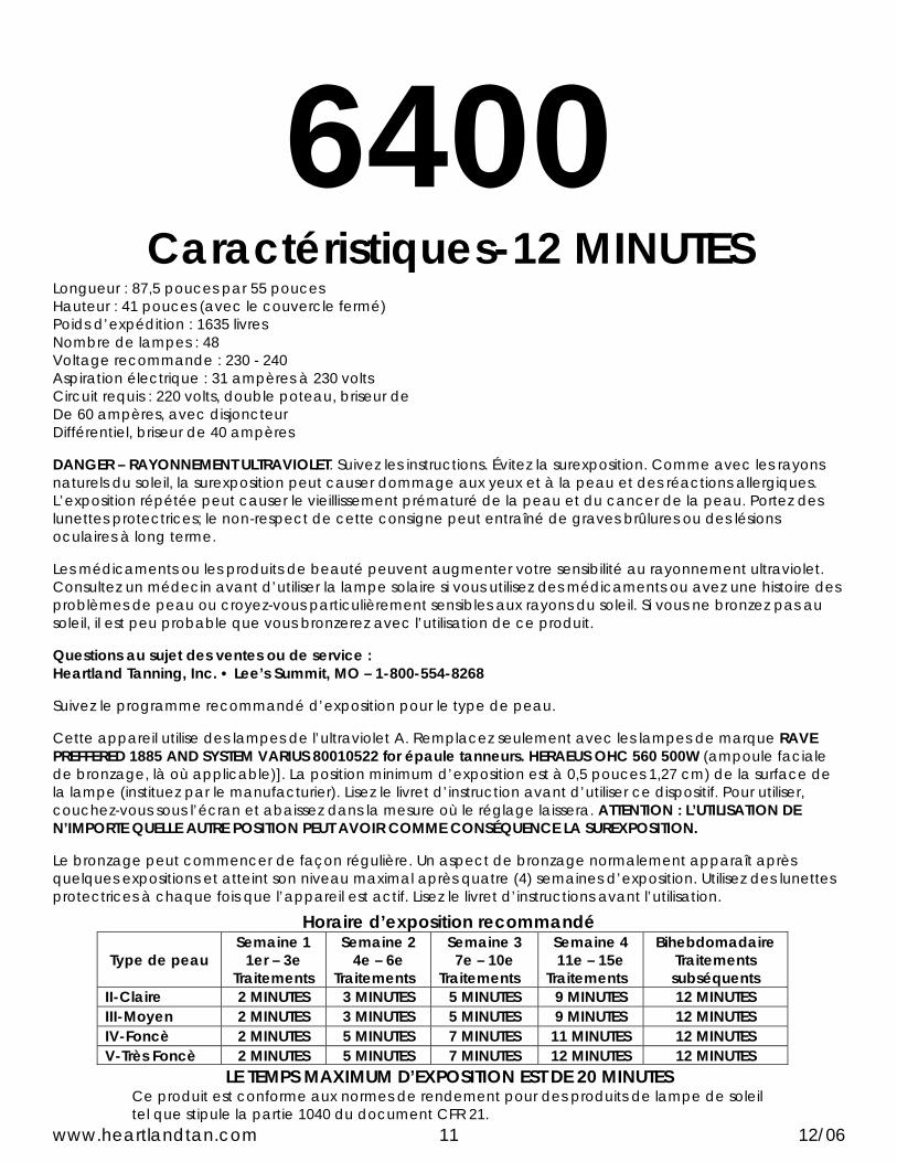
Longueur : 87,5 pouces par 55 pouces Hauteur : 41 pouces (avec le couvercle fermé) Poids d’expédition : 1635 livres Nombre de lampes : 48 Voltage recommande : 230 - 240 Aspiration électrique : 31 ampères à 230 volts Circuit requis : 220 volts, double poteau, briseur de De 60 ampères, avec disjoncteur Différentiel, briseur de 40 ampères DANGER – RAYONNEMENT ULTRAVIOLET. Suivez les instructions. Évitez la surexposition. Comme avec les rayons naturels du soleil, la surexposition peut causer dommage aux yeux et à la peau et des réactions allergiques. L’exposition répétée peut causer le vieillissement prématuré de la peau et du cancer de la peau. Portez des lunettes protectrices; le non-respect de cette consigne peut entraîné de graves brûlures ou des lésions oculaires à long terme. Les médicaments ou les produits de beauté peuvent augmenter votre sensibilité au rayonnement ultraviolet. Consultez un médecin avant d’utiliser la lampe solaire si vous utilisez des médicaments ou avez une histoire des problèmes de peau ou croyez-vous particulièrement sensibles aux rayons du soleil. Si vous ne bronzez pas au soleil, il est peu probable que vous bronzerez avec l’utilisation de ce produit. Questions au sujet des ventes ou de service : Heartland Tanning, Inc. • Lee’s Summit, MO – 1-800-554-8268 Suivez le programme recommandé d’exposition pour le type de peau. Cette appareil utilise des lampes de l’ultraviolet A. Remplacez seulement avec les lampes de marque RAVE PREFFERED 1885 AND SYSTEM VARIUS 80010522 for épaule tanneurs. HERAEUS OHC 560 500W (ampoule faciale de bronzage, là où applicable)]. La position minimum d’exposition est à 0,5 pouces 1,27 cm) de la surface de la lampe (instituez par le manufacturier). Lisez le livret d’instruction avant d’utiliser ce dispositif. Pour utiliser, couchez-vous sous l’écran et abaissez dans la mesure où le réglage laissera. ATTENTION : L’UTILISATION DE N’IMPORTE QUELLE AUTRE POSITION PEUT AVOIR COMME CONSÉQUENCE LA SUREXPOSITION. Le bronzage peut commencer de façon régulière. Un aspect de bronzage normalement apparaît après quelques expositions et atteint son niveau maximal après quatre (4) semaines d’exposition. Utilisez des lunettes protectrices à chaque fois que l’appareil est actif. Lisez le livret d’instructions avant l’utilisation.
Horaire d’exposition recommandé
Type de peau Semaine 1
1er – 3e Traitements
Semaine 2 4e – 6e
Traitements
Semaine 3 7e – 10e
Traitements
Semaine 4 11e – 15e
Traitements
Bihebdomadaire Traitements subséquents
II-Claire 2 MINUTES 3 MINUTES 5 MINUTES 9 MINUTES 12 MINUTES III-Moyen 2 MINUTES 3 MINUTES 5 MINUTES 9 MINUTES 12 MINUTES IV-Foncè 2 MINUTES 5 MINUTES 7 MINUTES 11 MINUTES 12 MINUTES V-Très Foncè 2 MINUTES 5 MINUTES 7 MINUTES 12 MINUTES 12 MINUTES
LE TEMPS MAXIMUM D’EXPOSITION EST DE 20 MINUTES Ce produit est conforme aux normes de rendement pour des produits de lampe de soleil tel que stipule la partie 1040 du document CFR 21.
www.heartlandtan.com 11 12/06

REPAIRS - SERVICE REPLACEMENT PARTS
LAMPS EYE PROTECTION
If you are in need of any of the above mentioned products or services, you should contact the dealer/distributor through whom you purchased your unit. In the event that you are unable to do so, please call our Service Department for assistance:
1-800-554-8268 NOTE: All repairs and replacement components including, but not limited to, protective eyewear, lamps, timers and acrylic must comply with CFR21 1040.20. NOTE: Electrical connection to the power supply must comply with NECA regulations and be performed by a qualified electrician.
WARNING Wear protective eyewear; failure to may result in severe burns or long-term injury to eyes.
www.heartlandtan.com 12 12/06

CARE AND CLEANING
After each session is completed, spray acrylic with a specially formulated UVT (ultra-violet transmitting) acrylic cleaner. Wipe the acrylic with a clean cloth. The acrylic should never be wiped with a dry cloth because this will generate a slight static charge which will attract dust. A mild liquid detergent and water solution can be used temporarily in place of acrylic cleaner.
ELECTRICAL SAFETY The tanning unit should be disconnected from the power supply before cleaning or any repairs are made! Avoid water or solution entering the lamp compartment.
CAUTION Do not use excessive amounts of water, any abrasive cleaners, or any spray cleaner that carry label warnings regarding reactions to contact with skin!
WARNING DO NOT USE ALCOHOL TO CLEAN THIS UNIT!
For maximum efficiency of your tanning unit, periodic cleaning of lamps is required. Refer to relamping instructions for acrylic removal.
www.heartlandtan.com 13 12/06

OVATION
LAMP GUIDE
www.heartlandtan.com 14 12/06

RELAMPING INSTRUCTIONS
CAUTION Replacement lamps must comply with CFR 21 1040.20 When ordering lamps, include model number and serial number.
5400 Replace only with Rave 160 APR 1841, Rave 12071 R 1989 & Hereaus E-400 HPT lamps for facial.
6400 Replace only with Rave PREFFERED 1885, System Varius 80010522 & Hereaus OHC 560 500W lamps for facial.
REPLACING LOW-PRESSURE TANNING LAMPS
5400 and 6400
BENCH 1. Disconnect power from unit. 2. Unlock the front bench acrylic locks (use 5/32 allen wrench) 3. Hinge the acrylic open by lifting up on the front edge.
Note: The acrylic should stay in the open position. 4. Remove the inner acrylic and set aside. (6400 only) 5. Turn the bi-pin lamp 90 degrees and remove from lamp holder. 6. Align the bi-pin lamp, slide the top and bottom into the lamp holder turn 90
degrees. 7. Reinstall inner acrylic (6400 only) 8. Clean and close the acrylic. 9. Use 5/32 allen wrench to lock bench acrylic. 10. Reconnect power to unit.
CANOPY 1. Disconnect power from unit. 2. Remove the screws from the canopy handle/acrylic retainer. 3. Holding the acrylic, hinge the handle/acrylic retainer open and remove
acrylic. 4. Turn the bi-pin lamp 90 degrees and remove from lamp holder. 5. Align the bi-pin lamp, slide the top and bottom into the lamp holder turn 90
degrees. 6. Clean acrylic and reinstall. 7. Hinge the handle/acrylic retainer closed and reinstall the screws. 8. Reconnect power to unit.
IMPORTANT NOTE – 2 people are required when removing and installing canopy acrylics on these units, 1 person at each end of bed.
www.heartlandtan.com 15 12/06

REPLACING HIGH-PRESSURE FACIAL LAMPS
5400 and 6400 1. Disconnect power from unit. 2. Remove two (2) quarter-turn fasteners at the front edge of the acrylic using a
#2 Phillips screwdriver. 3. Hinge the front handle/acrylic retainer down from the canopy allowing the
acrylic to hinge down from the back of the canopy. 4. Remove acrylic from the hinge rail exposing the facial assembly. 5. While holding the facial glass, press the two (2) retaining tabs back using your
thumb and set the facial glass aside. 6. Grasp the facial lamp from one end pressing towards the opposite end to
release the facial lamp from the lamp holder. 7. Replace the facial lamp.
NOTE ONLY GRASP FACIAL LAMP FROM EITHER END; ALWAYS USE ALCOHOL TOWEL PROVIDED WITH LAMP TO WIPE OFF LAMP AFTER INSTALLATION. 8. Reverse the procedures above to reassemble.
CAUTION DO NOT CHECK FACIAL LAMP OPERATION WITH FACIAL GLASS CASSETTE REMOVED. ALWAYS WEAR UV PROTECTIVE EYEWEAR WHEN REPLACING LAMPS AND CHECKING OPERATION.
www.heartlandtan.com 16 12/06

REPLACING HIGH-PRESSURE SHOULDER TANNER LAMPS
6400 1. Disconnect power from unit. 2. Hinge acrylic bench open. 3. Remove the glass reflector by pushing in and turning 90 degrees counter
clockwise and set aside. 4. Remove the aluminum reflector by removing two (2) #10-24 screws and lifting
straight up on the reflector. 5. Disconnect the shoulder tanners from the power source. 6. Remove the base from the mounting bracket by pressing down on the
retainer clips tabs and pulling outward on the base. Note: The base and lamp are one unit.
7. Discard the base and lamp assembly and install the new base to the mounting bracket.
Note DO NOT GRASP BY THE LAMP; ALWAYS USE ALCOHOL TO WIPE OFF LAMP AFTER INSTALLATION. 8. Reverse steps 1-6 to complete lamp change.
CAUTION ALWAYS WEAR UV PROTECTIVE EYEWEAR WHEN REPLACING LAMPS AND CHECKING OPERATION.
www.heartlandtan.com 17 12/06

TIMER GUIDE AND
INSTALLATION www.heartlandtan.com 18 12/06

OVERVIEW Congratulations on your purchase of Applied Digital, Inc.’s T-Max™ Series of tanning bed timers. The T-Max™ Series is designed for complete automation and control of your tanning equipment. A 5400/6400 Timer is an OEM board that can be installed in a tanning bed or tanning booth. Each 5400/6400 Timer can individually control a tanning bed, can be connected back-to-back with a T-Max™ 1A or T-MAX™ 3A for remote front desk control or be connected with many Heartland Timers and a T-Max™ Manager or Manager/Plus/Pro to control many beds from a remote location. Operation is accomplished via front panel controls. The licensed electrician installing your T-Max™ timing system should use this manual. Check for compliance with local building codes.
CONFIGURATION
Setting Bed Address Note: If you are using a T-Max™ Manager or T-Max™ Manager/Plus/Pro and multiple 5400/6400 Timers, remove power from the T-Max™ Manager or T-Max™ Manager/Plus/Pro and keep the power removed until all parameter changes are complete. 1. Press and hold the FAN UP button on the 5400/6400 Timer. As soon as you see, “Total Bed Hours”
release the button. This should take about 5-6 seconds. 2. Press the FAN UP button until the “Bed Address” screen is displayed. 3. Follow the directions displayed by pressing the TIME UP button to advance in number. Press the TIME
DOWN button to decrease in number. 4. To exit the program mode and make the 5400/6400 Timer available for the next session, press the
FAN UP button until the display shows the OVATION™ screen.
Preset Functions The 5400/6400 Timer is a user friendly sophisticated diagnostic tool that can be tailored to each user’s personal needs. From the display, the user can change the following preset functions.
1. START/STOP - By pressing this button the user can start or pause a session.
NOTE: Once a session has been started, all timer buttons are locked until the startup sequence has finished. In addition, once a session has been paused the high-pressure lamps will not restart until they have cooled. This may take up to 3 minutes depending on temperature.
2. TIME UP-TIME DOWN - When the unit is in manual mode these buttons are used to increase or decrease the session to the desired time. Once a session has started the TIME UP key has no function.
3. FACIAL UP-FACIAL DOWN - The 5400 has two facial settings, on or off. The 6400 FACIAL DOWN button lowers the output of the facial lamps from 500 watt to 300 watt to off. The FACIAL UP button raise the facials to 500 watts from the lower setting.
NOTE: Once the facials have been switched OFF, they will not cycle on until the lamps are ready. The display will show a 1 minute delay before the timer will attempt to restart the facials.
4. SHOULDER - This button cycles the shoulder tanning lamps ON/OFF. Note: Shoulder Tanners are not available on the 5400 model.
5. FAN UP-FAN DOWN - The FAN DOWN button lowers the body fan speed from 5 (ultra high) to 4 (high) to 3 (med.) to 2 (low) to 1 (ultra low) to 0 (off). The FAN UP button raises the body fan speed up to 5 (ultra high). The Salon Owner can monitor lamp hours, session’s totals and Tailor specific functions on the 5400/6400 Timer from their T-Max™ Manager. Level 3 security is required to “GET or SEND” parameters listed on page 47.
www.heartlandtan.com 19 12/06

Heartland 6400/5400 Parameters
Parameters not listed are unused or reserved
Parameter Range Function Default 255 Reset
1 1 – 128, 254, 255 Unit Address 1 *
3 0 - 255 Session Delay in minutes 3 * 5 Sessions 0 6 0 – 65535 Lamp Hours 0 7 0 – 65535 Bed Hours 0 8 0 – 65535 Manual Sessions 0 9 0, 1 Dirty function, 0 = off, 1 = on 1 * 10 0, 1 Key lock, 0 = off, 1 = on 0 * 15 0 – 65535 Unchangeable Session Count 0 19 0, 1 TPI Enable, 0 = off, 1 = on 0 * 20 0 - 100 Default Session Volume 20 * 21 0 – 100 Default Idle Volume 10 * 29 0 – 100 Maximum Volume 100 *
30 0 - 7
Default Audio Source 0 – Line Input 1 – Aux Input 2 - FM Preset 1 3 – FM Preset 2 4 – FM Preset 3 5 – FM Preset 4 6 – FM Preset 5 7 - DMX 2 *
35
Last Error 92 = Current On Error 93 = Current Off Error 70 = Special Error (See Parm 36) 98 = Temperature Error
36 Last Special Error 3 = Voltage Error
46 0 – 255 Max Saved Bed Temperature 47 0 – 65535 Fraction Facial Lamp Hours 48 0 – 65535 Facial Lamp Hours 51 0 – 255 Fractional Lamp Hours 0 52 0 - 255 Fractional Bed Hours 0 70 0,1 Enable Line Input 1 * 71 0,1 Enable Aux Input 1 * 72 0,1 Enable FM Input 1 * 73 0,1 Enable DMX Input 0 * 75 0 - 100 Volume 0 0 * 76 0 - 100 Volume 1 2 * 77 0 - 100 Volume 2 5 * 78 0 - 100 Volume 3 10 * 79 0 - 100 Volume 4 15 * 80 0 - 100 Volume 5 20 * 81 0 - 100 Volume 6 25 * 82 0 - 100 Volume 7 30 * 83 0 - 100 Volume 8 35 * 84 0 - 100 Volume 9 40 * 85 0 - 100 Volume 10 45 *
Parameters above 62 only accessible with a T-Max Manager-Pro V418 or higher
Setting Temperature Parameters Setting Voltage Parameters
=eParameterTemperatur500
256×eTemperatur 07.1
VoltageameterVoltagePar =
Setting Current Sense Parameters 25.6×= CurrentameterCurrentPar
www.heartlandtan.com 20 12/06

To insure safety for the user and to protect the salon owner’s investment the 5400/6400 Timer has multiple levels of protection. If a fault occurs the 5400/6400 Timer will shut down and display the fault. If the salon is running on a T-Max™ system the front controlling timer will sound an alarm and display a fault. The display on the 5400/6400 Timer will prompt you to reset if possible. If you have a fault that will not allow you to reset, cycle the power to the unit OFF and then back ON. If this still does not allow you to resume use refer to the owner’s manual and any stored faults can be accessed from a T-Max™ controlling timer. The possible stored faults will be found in parameter 35 and 36. These faults are listed below. Parameter 35 Last Error 92 = Current On Error 93 = Current Off Error 70 = Special Error (check parameter 36 for details) 98 = Temperature Error Parameter 36 Last Special Error Stored 3 = Voltage Error Trouble Shooting Procedure 3 = Voltage Error-Turn Power OFF before any type of maintenance is started.
1. Cycle power OFF and then back ON. Check display to see if fault resets. IF the fault does not reset a voltage measurement will need to be taken at the control box. If voltage is above or below the preset value, a Buck/Boost transformer may be needed.
2. If no problem is found, contact the manufacture for assistance.
REMOTE SINGLE BED CONTROL Remote Single Bed Control is the ability to control a single tanning bed from a remote location. T-Max™ 3A at the remote location is required for this configuration.
Wiring Wire the Heartland Timer to the tanning bed. Apply power to the T-Max™ 3A as described in their respective User’s Guides. Run the provided modular cable from the tanning room to the remote T-Max™ 3A. Connect the modular cable to one of the RJ-22 ports on the Heartland Timer and T-Max™ 3A (see RJ-22 ports for T-Max™ Series timers on page 16, figure B).
Configuration Set the address on the Heartland Timer in the tanning room to 1. Set the address on the T-Max™ 3A to 0. For setting the delay, refer to the T-Max™ 3A user’s guide. Note: When setting the address on the Heartland Timer in the tanning room, the power to the front desk T-Max™ 3A must be off.
www.heartlandtan.com 21 12/06

SESSION CONTROLS
Starting a Session 1. Press the Up and Down button on the T-Max™ 3A at the front desk until the session time is
displayed. Time cannot be set from the Heartland Timer in the room. 2. Press the Start/Stop button on the front desk T-Max™ 3A to start the session. If a delay other
than 0 is set, the delay will count down. A period on the lower right corner of the display will flash rapidly. When the session starts, the period will flash at once per second rate. If a 0 delay is entered, the session will start immediately.
Pausing a Session Pause the tanning session by pressing the Start/Stop button on the Heartland Timer in the tanning room. The flashing period on the lower right corner of the display will stop flashing and stay illuminated. To restart the session, press the Start/Stop button on the Heartland Timer in the tanning room. The period will continue flashing. NOTE: The session time will continue to count down. The display will continue to update and reflect the remaining session time.
Canceling a Session To cancel a session, press both the Start/Stop and Up button on the T-Max™ 3A at the front desk simultaneously. The session cannot be canceled from the Heartland Timer.
USING THE HEARTLAND TIMER WITH A T-MAX™ MANAGER OR T-MAX™ MANAGER/PLUS/PRO If you are using Heartland Timers with a T-Max™ Manager or T-Max™ Manager/Plus/Pro, follow these instructions for proper operation: 1. Set the address on each Heartland Timer. NOTE: If you need to set the address on the Heartland Timer manually, be sure to set each Heartland Timer to a different address. No Heartland Timer should be set to address 00. 2. Connect each Heartland Timer together using a modular cable that conforms to the pin-
outs shown on Figure D page 53. Connect T-Max™ Manager or T-Max™ Manager/Plus/Pro to the closest Heartland Timer in the line (refer to page 54).
NOTE: the T-Max™ Manager, the T-Max™ Manager/Plus/Pro or the software you are using if you are using a computer, controls Delay. It is not necessary to set the delay on the Heartland Timer. Refer to the T-Max™ Manager or T-Max™ Manager/Plus/Pro User’s Guide for operation.
www.heartlandtan.com 22 12/06

OTHER FEATURES
Clean Room Once a session time has elapsed, the display will show the session as over and that the bed needs cleaning. To clear the clean room indication, press and hold the Up button on the 5400/6400 Timer in the tanning room until the Ovation screen appears. To disable the clean room feature, set parameter 9 to a 0.
Cool Down Mode The cool down mode is when the bed cools down after a session has ended. The factory default setting is 10 minutes. Once the bed has been cleaned a new session can be sent to the 5400/6400 timer while in cool down mode.
Lamp Hours Used to check and change Lamp Hours (or any other parameter). TPI (Third Party Input) Mode If you are using a FST or Database Series timers, you will need to place the 5400/6400 Timer in the TPI mode. Connecting the TPI Input: 1. Set Parameter 19 to a 1.
2. Connect the two contact wires from the in room start button from the FST or database
timer system to the J4 connection. Operating in TPI Mode: When a session is started, the closed contact will be applied to the TPI input. The display on the 5400/6400 Timer will show the maximum time and count down. When the session ends, the closed contact will be removed from the TPI input and the bed will turn off. Any remaining session time showing on the 5400/6400 Timer will be eclipsed. NOTE: The 5400/6400 timer cannot be used as a stand alone timer in the TPI Mode.
www.heartlandtan.com 23 12/06

5400 DISPLAY AND POWER BOARD
FIGURE A – FRONT VIEW OF 5400 DISPLAY
FIGURE B – 5400 POWER BOARD LOCATIONS
www.heartlandtan.com 24 12/06

6400 DISPLAY AND COMMUNICATION BOARD
FIGURE C – FRONT VIEW OF 6400 DISPLAY
FIGURE D – 6400 COMMUNICATION BOARD LOCATIONS
www.heartlandtan.com 25 12/06

CONNECTING THE HEARTLAND TIMER TO A T-MAX™ SERIES
Optional
TPM
It dfrom
www.hea
Front Desk LocationFront Desk Location
-Max™ Manager/
lus/Pro or T-Max™
anager
oesn’t matter in which order the rooms are con the T-Max Manager through each room in th
rtlandtan.com
50’ modular cable with RJ-22 connectors are used to connect the series as shown
nected. The only requirement is that there is a continuous connection e T-max series daisy-chain.
26 12/06

5400 & 6400 Audio System
The Ovation 5400 and 6400 are equipped with the same audio system. The salon owner can preset (5) FM radio stations and connect to a salon music system. The salon clients can connect their own MP3 or iPod along with their headphones.
Changing Audio System Default Settings The tanning bed must not be running when making changes to the Audio System. There are 4 Audio System set up screens, Station Setup, Default Idle Volume, Default Session Volume and Default Audio Source.
Changes can be made by using the display on the bed. Hold down the FAN UP button until #7 Total Bed Hours screen appears. Push the FAN UP button until the Station Setup screen appears. Here you will have a list of options. Follow the display screen options below to preset your favorite FM Stations. Face Up For Next Preset – Program FM preset stations 1 – 5. Time Up To Seek – Finds next higher station. Time Down To Save – Saves selected station to preset number. Start / Stop to Exit – To exit out of Setup screen. Fan Up For Next Screen – To go to next screen.
After presetting the FM radio stations push the FAN UP button once. The display screen will show #21 Default Idle Volume 10. The number 10 indicates the volume level of the Audio System when the bed is not in use or idle. To change this default setting, push the TIME UP button to increase the volume level or the TIME DOWN to decrease the volume level. Press the START / STOP button to exit or push the FAN UP button to go to the next screen.
The next display screen will show #20 Default Session Volume 40. The number 40 indicates the volume level of the Audio System when the SESSION begins. To change this default setting, push the TIME UP button to increase the volume level or the TIME DOWN to decrease the volume level. Press the START / STOP button to exit or push the FAN UP button to go to the next screen.
The next display screen will show # 30 Default Audio Source 2. The number 2 indicates the bed will play the FM preset station that you have selected for preset station #1 when the bed is not in use or idle. You have a choice of 7 Audio Source settings. 0 = Line Input, 1 = Aux Input, 2 = FM Preset 1, 3 = FM Preset 2, 4 = FM Preset 3, 5 = FM Preset 4 and 6 = FM Preset 5. To change this default setting, push the TIME UP button or the TIME DOWN button. Press the START / STOP button to exit or push the FAN UP button to go to the next screen.
AUX Connect the MP3 or iPod to the MP3 / iPod jack located at the head end of the bed. Once the session has started, push the TIME UP button on the display until AUX is displayed at the top of the display screen. From here you are able to control the volume by pushing the VOLUME UP or VOLUME DOWN buttons on the display. Use the controls on the MP3 / iPod to select music.
Line If there is a music system in the salon, you may connect to the audio board so the salon music will be played in the tanning bed. Once the session has started, push the TIME UP button on the display until LINE is displayed at the top of the display screen. From here you are able to control the volume by pushing the VOLUME UP or VOLUME DOWN buttons on the display.
Headphones The headphone jack is located at the head end of the bed. When headphones are plugged in, the tanning bed speakers will not function.
www.heartlandtan.com 27 12/06

INSTALLATION INSTRUCTIONS
www.heartlandtan.com 28 12/06

5400 INSTALLATION INSTRUCTIONS
The 5400 tanning bed is a completely assembled unit when shipped. Disassembly is required to get it to its final location in the tanning room. Follow the instructions below on disassembly and reassembly of this unit. To complete the installation three people are required. If at any time during installation, you have a question call our service department @ 800/554-8268 before proceeding any further.
TOOLS NEEDED: • 7/16" Socket or Wrench, 9/16" Socket or Wrench • 5/16" Allen Wrench • #2 Phillips Screwdriver • Side cutters
STEP 1. Uncrate your 5400 unit and discard packaging. Note: If the size of your tanning room door is, greater than 36” skip to step #5.
STEP 2. Remove the filter and (3) three screws underneath the filter that attach canopy end caps to the frame. Hold onto the end cap while removing the last screw.
STEP 3. Carefully remove canopy skin. Note the red and black wires under the light display that need to be unplugged. Three people needed for this step. This is a delicate and easily damaged piece. Set in a secure location until you are ready to reinstall. Do not stand on end.
STEP 4. Using the 5/16 Allen wrench provided unlock the bench acrylic and lift acrylic to the up position. See picture 4.
STEP 5. Unplug the ground wires on the front of each ballast tray and the two connected to the bench. See picture 2
STEP 6. On the base door, unplug the red and gray RCA jacks noting that the red is on the bottom and the gray is on the top. Unplug the 4-pin connector (top right) and the speaker wires (left to right) white, black, green and red. Unthread the antenna from the audio amp.
STEP 7. Push the RCA’s jacks, 4-pin connector and the speaker wire through the hole with the grommet that is located on the left-hand side of the base. See picture 7 for reference.
STEP 8. Unplug the display cable located on the bottom left board and unplug T-1 on the component tray. Then unplug the ground wire coming from the base door to the component tray. Remove base door and set aside. Note the wing nut and safety cable attached to the right side.
STEP 9. Unplug wire harnesses from ballast trays B1, B2,B3,B4,C1,C2,C3,C4,C5,C6 and P1 through P12 including plugs “BF” and “1” from the ballast trays inside the base; note the numbers. See Picture 1. Cut the cable ties on the front of each ballast trays and carefully remove ballast trays, noting positions.
STEP 10. Loosen the (2) two cord plates at the back of the base, Pull the canopy harnesses through the holes. Take care in removing so that no damage occurs to the wires or connectors.
www.heartlandtan.com 29 12/06

540INSTALLATION IN
STEP 11. Using a 7/16 wrench or socket loosen the (2the canopy straight up as a team at the sacanopy to the side. Note the canopy is in there.
STEP 12. Underneath each end of the bench, unpluwires to prevent damage. Remove the benretaining screws on each side of the bed apicture 3 for proper handling.
STEP 13. Remove the (4) four screws that fasten the and (2) two are in the back rail. Also on thethe base covers to the bench. See picture
STEP 14. Lift the bench straight up and out, set asidcomplete this step. A third person needs picture 6.
Picture 1
www.heartlandtan.com 30
0 STRUCTIONS
) two bolts located on the canopy arm. Lift me time. See picture 9 Carefully set the he up position. A third person will be helpful
g each body fan cord. See Picture 10. Secure ch end caps by first loosening the (4) four nd lift up and out on the end caps. See
bench to the base (2) two are in the front rail backside there are (4) four screws that hold 5 e. Three people at each end are required to
to hold the cords so no damage occurs. See
Picture 2
Picture 4
Picture 3
12/06

5400 INSTALLATION INSTRUCTIONS
Picture 5
Picture 6
www.heartlandtan.com 31 12/06

5400 INSTALLATION INSTRUCTIONS
With the 5400 base ready to move. Refer to picture below showing the minimum clearance needed from the wall. Using Masking tape to mark the position on the floor where the corners of the base will go.
1) Place the base in the area you have marked.
2) Install the ballast trays; refer to your notes and picture 2 for proper placement.
3) Connect cords P1 through P12.
4) Set the bench in place and install the screws removed earlier. Refer to picture 4 for the backside positions. Be sure to position centering tabs to the inside for proper alignment. The bench cords must drop straight down, do not let them get pinched. Refer to picture 6.
5) Connect cords B1, B2, B3 AND B4 along with cord BF.
6) Install canopy and tighten lift arm screws to secure canopy to the lift arms. See picture 13
7) Place canopy cords back inside the base and install cord plates. Take care not to damage wiring or plugs. Refer to picture 5.
8) Connect cords C1, C2, C3, C4, C5, C6 and the cords labeled as 1 and F1
9) Position bench end caps back into place. Be sure that the speaker wires are at the head end of the bed. See picture 3 for proper handling, picture 6 for wires only.
www.heartlandtan.com 32 12/06

5400 INSTALLATION INSTRUCTIONS
10) Secure the end caps to the base by tightening the 4 screws that are on each end of the bench. Plug in each BF cord on the body fan attached to each end cap.
11) Reinstall rubber grommet and the RCA jacks, 4-pin connector and the speaker wire back in it location on the base. Take in not damaging the wire or connections. See picture 7.
12) Next get the base door and set it in place, in the open position.
13) Plug in the display cord, RCA jacks, 4-pin connector, speaker wire and the ground wire coming from the component tray. Reattach antenna to audio amp. See picture 12
14) Plug in the ground wires for each ballast tray and the two that go to the top of the base. Refer to picture 2.
15) Close the base door and tighten down top bolts.
16) Unlock bench Canopy (See picture 4) and raise it to the up position. Unwrap and carefully install front façade. Lower bench acrylic and lock in place (picture 4) NOT DOING THIS WILL CREATE AN AIRFLOW PROBLEM, VOID YOUR WARRANTY AND DIMINISH THE LIFE OF THIS UNIT.
17) Carefully install canopy skin. Set the backside in to slot on the rail (as shown in picture 8), one person will need to go around to the front and plug in the red and black wires while holding up that side. The other person will need to make sure that the cords are properly in the cord notch and that the exhaust fans have moved into position. Place front edge into its slot on the front rail.
18) Install canopy end caps, check for proper alignment. Tighten all bolts (10-24 x 1 ¼) and install filters.
19) Carefully place Ovation and 5400 plates in position.
Picture 7
Picture 8
www.heartlandtan.com 33 12/06

5400 INSTALLATION INSTRUCTIONS
Picture 9
Picture 10
Picture 12 Picture 13
www.heartlandtan.com 34 12/06

INSTALLATION INSTRUCTIONS
www.heartlandtan.com 35 12/06

6400 INSTALLATION INSTRUCTIONS
The 6400 tanning bed is a completely assembled unit when shipped. Disassembly is required to get it to its final location in the tanning room. Follow the instructions below on disassembly and reassembly of this unit along with your taking of notes. To complete the installation three people are required. IF YOU HAVE A QUESTION AT ANY TIME DURING THIS INSTALLATION, STOP AND CALL OUR SERVICE DEPARTMENT @ 800/554-8268 BEFORE PROCEEDING ANY FURTHER.
TOOLS NEEDED: • 7/16" Socket or Wrench, 9/16" Socket or Wrench • 5/16" Allen Wrench (provided) • #2 Phillips Screwdriver • 5/16 nutdriver
STEP 1. Uncrate your 6400 unit and discard packaging.
Note: If the size of your tanning room door is, greater than 36” skip to step #5.
STEP 2. Remove the filter and (3) three screws underneath the filter that attach canopy end caps to the frame. Hold onto the end cap while removing the last screw.
STEP 3. Carefully remove canopy skin by lifting up on both sides. DO NOT SCRATCH THE YELLOW SECTION IN ANY WAY. *** SCRATCHES ARE NOT COVERED BY WARRANTY ***. You will need a third person here. One person will need to hold up the front side as another makes sure that the canopy skin clears the exhaust fans and canopy cable harness. Lift skin up and away from canopy frame. This is a delicate and easily damaged piece. Set in a secure location until you are ready to reinstall. Do not stand on end. See picture 11
STEP 4. Using the 5/16 Allen wrench provided unlock the bench acrylic and lift acrylic to the up position. See picture 1.
STEP 5. Open the base door and unplug the RCA jacks. Unplug the 4-pin connector, the red display cable and the speaker wires along with the Lt. Blue and tan wire connector. Unthread the antenna from the audio amp. See picture 2.
STEP 6. Remove the three screws that attach the left-hand back light panel to the base. Do not set aside until completing step 7. See picture 3
STEP 7. Push the RCA’s jacks, 4-pin connector and the speaker wire through the hole with the grommet that is located on the left-hand side of the base. Then take left-hand back light panel to a safe area until needed. See picture 10
STEP 8. Unplug the display cable located on the bottom left board and plugs labeled T-1, T-2 and S-1 inside the base (front and back left). Then unplug the ground wire coming from the base door to the component tray. Remove base door and set aside. Note the wing nut on the right that secures the safety cable.
STEP 9. Unplug wire harnesses from the ballast trays B1,B2,B3,B4,C1,C2,C3,C4,C5,C6,F1 and P1 through P12 including plugs “BF” and “1” from the ballast trays inside the base; note the numbers.
www.heartlandtan.com 36 12/06

6400 INSTALLATION INSTRUCTIONS
STEP 10. Unplug the ground wires (picture 6) on the front of each ballast tray and the two connected to the bench. Also, unplug the temperature switch located on the base shown in picture 5.
STEP 11. Cut the cable ties on the front of the ballast trays and remove ballast trays, noting positions.
STEP 12. Loosen the two cord plates at the back of the base and pull the canopy harnesses through the holes. Take care in removing so that no damage occurs to the wires and connectors. See picture 4
STEP 13. Using a 7/16 wrench or socket loosen the (2) two bolts located on the canopy arm. Lift the canopy straight up as a team at the same time. Carefully set the canopy to the side. Note the canopy is in the up position. A third person will be helpful here.
STEP 14. Underneath each end of the bench, unplug the body fan cords. Secure wires to prevent damage. Disconnect the body fan hoses from the bench. Do not disconnect at the body fan. See pictures 7, 13 and 14.
STEP 15. Remove the bench end caps by first loosening the (4) four retaining screws on each side and lifting up and out on the end caps. See picture 8 for proper handling of end caps when removing.
STEP 16. Remove the (4) four screws that fasten the bench to the base (2) two are in the front rail and (2) two are in the back rail. Also on the backside there are (4) four screws that hold the base covers to the bench. See picture 4
STEP 17. Lift the bench straight up and out, set aside. Three people are required to complete this step. A third person to hold the cords so no damage occurs. See picture 9
Picture 1
Picture 3
Picture 2
www.heartlandtan.com 37 12/06

6400 INSTALLATION INSTRUCTIONS
Picture 8
Picture 4
Picture 6
Picture 5
www.heartlandtan.com 38
Picture 9Picture 7
12/06

6400 INSTALLATION INSTRUCTIONS
With the 6400 base ready to move. Refer to picture below showing the minimum clearance from the wall on the floor where the corners of the base will go.
1) Place the base in the area you have marked.
2) Install the ballast trays; refer to your notes and Picture 6 for proper placement.
3) Connect cords P1 through P12.
4) Set the bench in place. Be sure to position centering tabs to the inside for proper alignment. The bench cords must drop straight down do not let them get pinched. Refer to picture 9
5) Install shoulder tanner glass reflectors. Carefully place over lamp and turn 90º clockwise.
6) Connect cords B1, B2, B3 AND B4 along with cord BF.
7) Install canopy and tighten the two lift arm screws that secure canopy to the lift arms. See picture 15
8) Place canopy cords back inside the base and install cord plates. Be careful not to damage wires or the plugs.
9) Connect cords C1, C2, C3, C4, C5, C6 and the cords labeled as 1, F1
www.heartlandtan.com 39 12/06

6400 INSTALLATION INSTRUCTIONS
10) Position bench end caps back into place. Be sure that the speaker wires are at the head end of the bed. See picture 10 and picture 8 for proper handling.
11) Secure each end cap to the base by tightening the four screws on each end cap. Plug in each BF cord to the body fan attached to each end cap. See picture 7.
12) Set the base door (attach door safety cable) and left-hand back light panel in place, in the open position. (Protect back light lamp)
13) Push the RCA jacks, 4-pin connector, speaker wire and back light panel wires back through the hole and reinstall the grommet. Secure back light panel to base. See picture 3.
14) Plug in the display cord, RCA jacks, 4-pin connector, speaker wire and the ground wire coming from the component tray. Reattach antenna to audio amp. Refer to picture 2
15) Plug in the ground wires for each ballast tray and the two that go the top of the base. Refer to picture 6. Also, be sure that you plug in the temperature switch. See picture 5.
16) Close the base door and tighten down bolts.
17) Unwrap and carefully install front façade. See picture 12. DO NOT SCRATCH THE YELLOW SECTION IN ANY WAY. *** SCRATCHES ARE NOT COVERED BY WARRANTY ***. This is a delicate and easily damaged piece.
18) Set the bench acrylic in the down position and lock into place using the 5/32 Allen wrench provided. NOT DOING THIS WILL CREATE AN AIRFLOW PROBLEM, VOID YOUR WARRANTY AND DIMINISH THE LIFE OF THIS UNIT.
19) Carefully install canopy skin. DO NOT SCRATCH THE YELLOW SECTION IN ANY WAY. *** SCRATCHES ARE NOT COVERED BY WARRANTY ***. Set the backside in to slot on the rail, one person will need to go around to the front to hold up that side. The other person will need to make sure that the cords are properly in the cord notch and that the exhaust fans have moved into position. Place front edge into its slot on the front rail. See picture 11
20) Install canopy end caps, check for proper alignment. Tighten all bolts (10-24 x 1 ¼) and install filters.
21) Reconnect the body fan hoses to the underside of the bench. THE HOSE COMING FROM THE FOOT END MUST BE CONNECTED TO THE BACKSIDE VENT OPENING. Tighten as shown in pictures 13 and 14
www.heartlandtan.com 40 12/06

6400 INSTALLATION INSTRUCTIONS
Picture 10
Picture 11
Picture12
www.heartlandtan.com 41 12/06

6400 INSTALLATION INSTRUCTIONS
Picture 13
Picture 15
Picture 14
www.heartlandtan.com 42 12/06

5400 / 6400
WIRING GUIDE
www.heartlandtan.com 43 12/06

12
43
12
24
68
1012
1816
1420
2422
26
FRO
NT
FRO
NT
CA
NO
PYBE
NC
H
5400
CA
NO
PY L
AM
PS (1
-24)
F
AC
IALS
(1-3
)64
00 C
AN
OPY
LA
MPS
(1-2
6)
FA
CIA
LS (1
-4)
5400
BEN
CH
LAM
PS (1
-16)
6400
BEN
CH
LAM
PS (1
-18)
S
HOUL
DER
(1-2
)
13
57
911
1315
17
24
86
1412
1016
18
13
57
911
1315
2119
1725
23
D C B
ABCD
12
34
56
788
76
54
32
1
EF
EF
SHEE
T 1 O
F 1
UNLE
SS O
THER
WIS
E SP
ECIF
IED
:
SCA
LE: 1
:4.5
WEI
GHT
:
REV
DW
G.
NO
.
CSIZE
TITLE
:
DRA
WN
BY:
FIN
ISH
MA
TERI
AL
DIM
ENSI
ON
S A
RE IN
INC
HES
TOLE
RAN
CES
:FR
AC
TION
AL
1/1
6"A
NG
ULA
R: B
END
.5
°TW
O P
LAC
E D
ECIM
AL
.0
30TH
REE
PLA
CE
DEC
IMA
L
.015
HOLE
S: +
.010
-.00
5HA
RDW
ARE
HO
LES:
+.0
03 -.
000
PRO
PRIE
TARY
AN
D C
ON
FIDE
NTIA
LTH
E IN
FORM
ATIO
N C
ON
TAIN
ED IN
THI
SD
RAW
ING
IS T
HE S
OLE
PRO
PERT
Y O
FHE
ART
LAN
D T
AN
NIN
G IN
C.
AN
Y RE
PRO
DUC
TION
IN P
ART
OR
AS
A W
HOLE
WITH
OUT
THE
WRI
TTEN
PER
MIS
SIO
N O
FHE
ART
LAN
D T
AN
NIN
G IN
C. I
S PR
OHI
BITE
D.
A
5400
640
0 LA
MP
LAYO
UT
www.heartlandtan.com 44 12/06

GL1 L3L2
C1
B1F1
F2S1
A1
A1
A1
A1
A1
SAFETY LOOP
THER
MA
L SW
ITCH
CA
NO
PY 2
50°
6400
ON
LY
6400
ON
LY
5400
ON
LY
CA
NO
PYBA
CK
LIG
HTIN
G
HEA
D E
ND
BOD
Y FA
N
FAN
RELA
Y
TERM
INA
LST
RIP
FOO
T EN
DBO
DY
FAN
CA
NO
PYC
OO
LIN
G F
AN
#1
BEN
CH
CO
OLI
NG
FA
NC
AN
OPY
CO
OLI
NG
FA
N#
2
D C B
ABCD
12
34
56
788
76
54
32
1
EF
EF
SHEE
T 1 O
F 1
5400
640
0 FA
N A
ND
BL
WD
UNLE
SS O
THER
WIS
E SP
ECIF
IED
:
SCA
LE: 1
:3W
EIG
HT:
REV
DW
G.
NO
.
CSIZE
TITLE
:
DRA
WN
BY:
FIN
ISH
MA
TERI
AL
DIM
ENSI
ON
S A
RE IN
INC
HES
TOLE
RAN
CES
:FR
AC
TION
AL
1/1
6"A
NG
ULA
R: B
END
.5
°TW
O P
LAC
E D
ECIM
AL
.0
30TH
REE
PLA
CE
DEC
IMA
L
.015
HOLE
S: +
.010
-.00
5HA
RDW
ARE
HO
LES:
+.0
03 -.
000
PRO
PRIE
TARY
AN
D C
ON
FIDE
NTIA
LTH
E IN
FORM
ATIO
N C
ON
TAIN
ED IN
THI
SD
RAW
ING
IS T
HE S
OLE
PRO
PERT
Y O
FHE
ART
LAN
D T
AN
NIN
G IN
C.
AN
Y RE
PRO
DUC
TION
IN P
ART
OR
AS
A W
HOLE
WITH
OUT
THE
WRI
TTEN
PER
MIS
SIO
N O
FHE
ART
LAN
D T
AN
NIN
G IN
C. I
S PR
OHI
BITE
D.
A
www.heartlandtan.com 45 12/06

L1 L2 L3 F1F2
P8P7
F1
21
34
5400
FA
CIA
L LA
MPS
(1-3
)64
00 F
AC
IAL
LAM
PS (1
-4)
6400
ON
LY
SAFETY SWITCH
D C B
ABCD
12
34
56
788
76
54
32
1
EF
EF
SHEE
T 1 O
F 1
5400
640
0 FA
CIA
L W
D
UNLE
SS O
THER
WIS
E SP
ECIF
IED
:
SCA
LE: 1
:3W
EIG
HT:
REV
DW
G.
NO
.
CSIZE
TITLE
:
DRA
WN
BY:
FIN
ISH
MA
TERI
AL
DIM
ENSI
ON
S A
RE IN
INC
HES
TOLE
RAN
CES
:FR
AC
TION
AL
1/1
6"A
NG
ULA
R: B
END
.5
°TW
O P
LAC
E D
ECIM
AL
.0
30TH
REE
PLA
CE
DEC
IMA
L
.015
HOLE
S: +
.010
-.00
5HA
RDW
ARE
HO
LES:
+.0
03 -.
000
PRO
PRIE
TARY
AN
D C
ON
FIDE
NTIA
LTH
E IN
FORM
ATIO
N C
ON
TAIN
ED IN
THI
SD
RAW
ING
IS T
HE S
OLE
PRO
PERT
Y O
FHE
ART
LAN
D T
AN
NIN
G IN
C.
AN
Y RE
PRO
DUC
TION
IN P
ART
OR
AS
A W
HOLE
WITH
OUT
THE
WRI
TTEN
PER
MIS
SIO
N O
FHE
ART
LAN
D T
AN
NIN
G IN
C. I
S PR
OHI
BITE
D.
A
www.heartlandtan.com 46 12/06

L1L1
L2 L3L2 L3
C1
C1
P1 P2C2
P3 C3
C4
P4
P5 C5
P6C6
12
34
56
78
910
1112
1314
1516
1718
2625
2423
2221
2019
5400
CA
NO
PY L
AM
PS (1
-24)
6400
CA
NO
PY L
AM
PS (1
-26)
D C B
ABCD
12
34
56
788
76
54
32
1
EF
EF
SHEE
T 1 O
F 1
5400
640
0 C
AN
OPY
LA
MP
WD
UNLE
SS O
THER
WIS
E SP
ECIF
IED
:
SCA
LE: 1
:3W
EIG
HT:
REV
DW
G.
NO
.
CSIZE
TITLE
:
DRA
WN
BY:
FIN
ISH
MA
TERI
AL
DIM
ENSI
ON
S A
RE IN
INC
HES
TOLE
RAN
CES
:FR
AC
TION
AL
1/1
6"A
NG
ULA
R: B
END
.5
°TW
O P
LAC
E D
ECIM
AL
.0
30TH
REE
PLA
CE
DEC
IMA
L
.015
HOLE
S: +
.010
-.00
5HA
RDW
ARE
HO
LES:
+.0
03 -.
000
PRO
PRIE
TARY
AN
D C
ON
FIDE
NTIA
LTH
E IN
FORM
ATIO
N C
ON
TAIN
ED IN
THI
SD
RAW
ING
IS T
HE S
OLE
PRO
PERT
Y O
FHE
ART
LAN
D T
AN
NIN
G IN
C.
AN
Y RE
PRO
DUC
TION
IN P
ART
OR
AS
A W
HOLE
WITH
OUT
THE
WRI
TTEN
PER
MIS
SIO
N O
FHE
ART
LAN
D T
AN
NIN
G IN
C. I
S PR
OHI
BITE
D.
A
www.heartlandtan.com 47 12/06

L1 L2 L3L3L2L1
B1
B1 B2 P10
P12
B4B3P11
13
42
87
65
918
1716
1514
1312
1110
5400
BEN
CH
LAM
PS (1
-16)
6400
BEN
CH
LAM
PS (1
-18)
SHO
ULDE
R LA
MPS
(1-2
)
12
TST-
250
SHO
ULDE
R TA
NN
ERS
6400
ON
LY
S1
P9
S1
D C B
ABCD
12
34
56
788
76
54
32
1
EF
EF
SHEE
T 1 O
F 1
5400
640
0 BE
NC
H LA
MP
WD
UNLE
SS O
THER
WIS
E SP
ECIF
IED
:
SCA
LE: 1
:3W
EIG
HT:
REV
DW
G.
NO
.
CSIZE
TITLE
:
DRA
WN
BY:
FIN
ISH
MA
TERI
AL
DIM
ENSI
ON
S A
RE IN
INC
HES
TOLE
RAN
CES
:FR
AC
TION
AL
1/1
6"A
NG
ULA
R: B
END
.5
°TW
O P
LAC
E D
ECIM
AL
.0
30TH
REE
PLA
CE
DEC
IMA
L
.015
HOLE
S: +
.010
-.00
5HA
RDW
ARE
HO
LES:
+.0
03 -.
000
PRO
PRIE
TARY
AN
D C
ON
FIDE
NTIA
LTH
E IN
FORM
ATIO
N C
ON
TAIN
ED IN
THI
SD
RAW
ING
IS T
HE S
OLE
PRO
PERT
Y O
FHE
ART
LAN
D T
AN
NIN
G IN
C.
AN
Y RE
PRO
DUC
TION
IN P
ART
OR
AS
A W
HOLE
WITH
OUT
THE
WRI
TTEN
PER
MIS
SIO
N O
FHE
ART
LAN
D T
AN
NIN
G IN
C. I
S PR
OHI
BITE
D.
A
www.heartlandtan.com 48 12/06

C1
B1F1
A1
A1
A1
A1
A2
A2
A2
A2
FAN
RELA
YTE
RMIN
AL
STRI
PL1
L2
15V
DC
-15
+15
COM
AUD
IOA
MP
1.5 A
F1
MA
INC
ON
TRO
LBO
ARD
FAN
SPEE
DC
ON
TRO
L
1 2
3 4
5 6
7 8
1 2
6 5 4 3 2 1
T1
P41
J5
5 A
F2
F310 A
THER
MA
L SW
ITCH
CA
NO
PY 2
50
D E L A Y
15W
220V
BASE
BA
CK
LIG
HT S
CRE
WIN
MIN
I LYN
X
1-9
1-8
L1 L2 L3 G
D C B
ABCD
12
34
56
788
76
54
32
1
EF
EF
SHEE
T 1 O
F 1
5400
TIM
ER W
D
UNLE
SS O
THER
WIS
E SP
ECIF
IED
:
SCA
LE: 1
:3.2
5 WEI
GHT
:
REV
DW
G.
NO
.
CSIZE
TITLE
:
DRA
WN
BY:
FIN
ISH
MA
TERI
AL
DIM
ENSI
ON
S A
RE IN
INC
HES
TOLE
RAN
CES
:FR
AC
TION
AL
1/1
6"A
NG
ULA
R: B
END
.5
°TW
O P
LAC
E D
ECIM
AL
.0
30TH
REE
PLA
CE
DEC
IMA
L
.015
HOLE
S: +
.010
-.00
5HA
RDW
ARE
HO
LES:
+.0
03 -.
000
PRO
PRIE
TARY
AN
D C
ON
FIDE
NTIA
LTH
E IN
FORM
ATIO
N C
ON
TAIN
ED IN
THI
SD
RAW
ING
IS T
HE S
OLE
PRO
PERT
Y O
FHE
ART
LAN
D T
AN
NIN
G IN
C.
AN
Y RE
PRO
DUC
TION
IN P
ART
OR
AS
A W
HOLE
WITH
OUT
THE
WRI
TTEN
PER
MIS
SIO
N O
FHE
ART
LAN
D T
AN
NIN
G IN
C. I
S PR
OHI
BITE
D.
A
www.heartlandtan.com 49 12/06

AUD
IOA
MP
J515V
DC
BASE
BAC
KLI
GHT
BALL
AST
C1
B1S1
F2F1
A1
A1
A1
A1
A1
A1
A2
A2
A2
A2
A2
A2
T1
FAN
RELA
Y
THER
MA
L SW
ITCH
CA
NO
PY 2
50
10 A
5 A
F2
F310
987
6543
21
1 2 3 45
BLA
CK
4 3 BR
OW
N2 1
BLUE
8765
4321
T2
J9
J3
J2
J4
+15
-15
COM
MA
IN C
ON
TRO
LBO
ARD
L1 L2 L3 G
1.5 A
F1
D C B
ABCD
12
34
56
788
76
54
32
1
EF
EF
SHEE
T 1 O
F 1
6400
TIM
ER W
D
UNLE
SS O
THER
WIS
E SP
ECIF
IED
:
SCA
LE: 1
:3.5 W
EIG
HT:
REV
DW
G.
NO
.
CSIZE
TITLE
:
DRA
WN
BY:
FIN
ISH
MA
TERI
AL
DIM
ENSI
ON
S A
RE IN
INC
HES
TOLE
RAN
CES
:FR
AC
TION
AL
1/1
6"A
NG
ULA
R: B
END
.5
°TW
O P
LAC
E D
ECIM
AL
.0
30TH
REE
PLA
CE
DEC
IMA
L
.015
HOLE
S: +
.010
-.00
5HA
RDW
ARE
HO
LES:
+.0
03 -.
000
PRO
PRIE
TARY
AN
D C
ON
FIDE
NTIA
LTH
E IN
FORM
ATIO
N C
ON
TAIN
ED IN
THI
SD
RAW
ING
IS T
HE S
OLE
PRO
PERT
Y O
FHE
ART
LAN
D T
AN
NIN
G IN
C.
AN
Y RE
PRO
DUC
TION
IN P
ART
OR
AS
A W
HOLE
WITH
OUT
THE
WRI
TTEN
PER
MIS
SIO
N O
FHE
ART
LAN
D T
AN
NIN
G IN
C. I
S PR
OHI
BITE
D.
A
www.heartlandtan.com 50 12/06

LIMITED WARRANTY
Heartland Tanning, Inc. warrants its products to be free from defects in materials and workmanship under intended normal use as described in the unit’s Operation and Instruction Manual, for a period of five (5) years from date of sale.
This Limited Warranty applies only to the original purchaser of the equipment through Heartland Tanning, Inc. or its authorized dealer or distributor, and is not transferable.
Heartland Tanning, Inc.’s obligations under this warranty are limited to repair or replacement of any defective part without charge for that part to the original purchaser, with the following exceptions:
A. Low Pressure tanning lamps are warranted against defects for a period of sixty (60) days from date of sale.
B. High Pressure tanning lamps are warranted against defects for a period of thirty (30) days from date of sale
C. Five (5) year Limited Warranty on parts. Only parts obtained through Heartland Tanning, Inc., its authorized dealers or distributors may be used. Transportation cost for parts shipped to the consumer and the return of defective parts to Heartland Tanning, Inc. are not included
D. Labor will be furnished without charge for one hundred eighty (180) days from the date of purchase only. All labor and related charges must be authorized by Heartland Tanning, Inc. prior to start of repairs, and must coincide with Heartland Tanning, Inc. established rates and time allotment policy.
E. All fans are warranted against defects for a period of five (5) years from date of sale.
F. Timer system warranted for one (1) year.
G. Acrylic, warranted for twelve (12) months prorated.
H. Springs warranted for twelve (12) months.
I. Filter Glass warranted for twelve (12) months.
It is imperative that the original customer completes and returns the enclosed warranty card within ten (10) days after purchase to insure valid registration and coverage for potential claims.
If the warranty card is not registered, proof of purchase from Heartland Tanning, Inc. or its authorized dealer or distributor will be required prior to any consideration on warranty claims. This could result in service delays.
This warranty is extended to the individual or legal entity, whose name appears on the warranty registration card filed with Heartland Tanning, Inc., or whose name appears on the original sale document and may not be transferred to any other individual or legal entity.
This warranty does not apply to any failure of the product or any parts of the product due to alterations, modifications, misuse, abuse, accident, improper maintenance and improper installation or if the serial number on the product has been removed, altered, or defaced. Adequate packaging must be used for returned goods to prevent freight damage.
THIS WARRANTY IS EXPRESSLY IN LIEU OF ALL OTHER WARRANTIES, EXPRESSED OR IMPLIED, INCLUDING THE WARRANTIES OF MERCHANTABILITY AND HEARTLAND TANNING, INC. NO PERSON, FIRM OR CORPORATION IS AUTHORIZED TO OBLIGATE HEARTLAND TANNING, INC. FOR ANY LIABILITY IN CONNECTION WITH THE SALE OR USE OF THESE GOODS.
This warranty gives you specific legal rights, and you may have other rights, which vary from state to state.
NOTICE: Any misuse, abuse, modifications, alteration, improper installation, etc. of this product or its intended use will subject said party to direct responsibility for any and all consequences resulting from such action. Furthermore, such actions will void all warranties and may relieve Heartland Tanning, Inc. of any liabilities relating to said product.
www.heartlandtan.com 51 12/06