4700p/4700e & 4800p/4800e
TRANSCRIPT

Masoneilan™
4700P/4700E & 4800P/4800E Pneumatic and Electropneumatic Positioners
Instruction Manual (Rev. F)
Baker Hughes Data Classification: Public

© 2021 Baker Hughes Company. All rights reserved.2 | Baker Hughes
About this GuideThis instruction manual applies to the Masoneilan 4700P/4700E & 4800P/4800E Pneumatic and Electropneumatic Positioners.
The information contained in this manual, in whole or part, shall not be transcribed or copied without Baker Hughes’ written permission.
In no case does this manual guarantee the merchantability of the positioner or the software or its adaptability to a specific client needs.
Please report any errors or questions about the information in this manual to your local supplier or visit valves.bakerhughes.com.
DISCLAIMERTHESE INSTRUCTIONS PROVIDE THE CUSTOMER/OPERATOR WITH IMPORTANT PROJECT-SPECIFIC REFERENCE INFORMATION IN ADDITION TO THE CUSTOMER/OPERATOR’S NORMAL OPERATION AND MAINTENANCE PROCEDURES. SINCE OPERATION AND MAINTENANCE PHILOSOPHIES VARY, BAKER HUGHES COMPANY (AND ITS SUBSIDIARIES AND AFFILIATES) DOES NOT ATTEMPT TO DICTATE SPECIFIC PROCEDURES, BUT TO PROVIDE BASIC LIMITATIONS AND REQUIREMENTS CREATED BY THE TYPE OF EQUIPMENT PROVIDED.
THESE INSTRUCTIONS ASSUME THAT OPERATORS ALREADY HAVE A GENERAL UNDERSTANDING OF THE REQUIREMENTS FOR SAFE OPERATION OF MECHANICAL AND ELECTRICAL EQUIPMENT IN POTENTIALLY HAZARDOUS ENVIRONMENTS. THEREFORE, THESE INSTRUCTIONS SHOULD BE INTERPRETED AND APPLIED IN CONJUNCTION WITH THE SAFETY RULES AND REGULATIONS APPLICABLE AT THE SITE AND THE PARTICULAR REQUIREMENTS FOR OPERATION OF OTHER EQUIPMENT AT THE SITE.
THESE INSTRUCTIONS DO NOT PURPORT TO COVER ALL DETAILS OR VARIATIONS IN EQUIPMENT NOR TO PROVIDE FOR EVERY POSSIBLE CONTINGENCY TO BE MET IN CONNECTION WITH INSTALLATION, OPERATION OR MAINTENANCE. SHOULD FURTHER INFORMATION BE DESIRED OR SHOULD PARTICULAR PROBLEMS ARISE WHICH ARE NOT COVERED SUFFICIENTLY FOR THE CUSTOMER/OPERATOR’S PURPOSES THE MATTER SHOULD BE REFERRED TO BAKER HUGHES.
THE RIGHTS, OBLIGATIONS AND LIABILITIES OF BAKER HUGHES AND THE CUSTOMER/OPERATOR ARE STRICTLY LIMITED TO THOSE EXPRESSLY PROVIDED IN THE CONTRACT RELATING TO THE SUPPLY OF THE EQUIPMENT. NO ADDITIONAL REPRESENTATIONS OR WARRANTIES BY BAKER HUGHES REGARDING THE EQUIPMENT OR ITS USE ARE GIVEN OR IMPLIED BY THE ISSUE OF THESE INSTRUCTIONS.
THESE INSTRUCTIONS ARE FURNISHED TO THE CUSTOMER/OPERATOR SOLELY TO ASSIST IN THE INSTALLATION, TESTING, OPERATION, AND/OR MAINTENANCE OF THE EQUIPMENT DESCRIBED. THIS DOCUMENT SHALL NOT BE REPRODUCED IN WHOLE OR IN PART WITHOUT THE WRITTEN APPROVAL OF BAKER HUGHES.
Copyright
All information contained herein is believed to be accurate at the time of publication and is subject to change without notice.
Copyright 2021 by Baker Hughes company. All rights reserved. PN 720014889-888- 0000 Rev. F.

Masoneilan 4700P/E & 4800P/E Positioners Manual | 3© 2021 Baker Hughes Company. All rights reserved.
Document Changes
Rev / Date Changes
B / 08-2014 Added paragraph to first page of Calibration section about post-shipment calibration.
C / 04-2015 Added Disclaimer paragraph and a new Figure 15.
D / 01-2020
Changed Valve Action references in High Performance Butterfly Valve cam and lever graphic in Calibration chapter.Removed Varimax, 39002, Paramax, 87U/88U and Ball II.Rebranded to Baker Hughes format.
E / 12-20 Added Lockwasher part to Figures 18 and 19.
F / 01-21 Added Lockwasher part to Figure 6.

© 2021 Baker Hughes Company. All rights reserved.4 | Baker Hughes
ContentsSafety Information .....................................................................................................................7
4700P/4700E and 4800P/4800E Product Safety ......................................................................8General installation, maintenance or replacement ..............................................................8Hazardous Area Installation ................................................................................................8
Introduction .............................................................................................................................10General Description and Operation ...................................................................................10Pilot ...................................................................................................................................11Direct Action ......................................................................................................................11Reverse Action ..................................................................................................................11Cam ...................................................................................................................................11Optional bypass valve (4700P, Direct Acting Model only) ................................................. 11
Installation ...............................................................................................................................12Mounting and Orientation ..................................................................................................12Cover Removal..................................................................................................................13
87/88 Actuator ..........................................................................................................................15Mounting 4700P and 4700E on Series 87/88 Actuators ....................................................17
Positioner Mounting and Orientation ....................................................................................19Camflex II, V-Max, MiniTork II, and Butterfly .....................................................................19
Pneumatic Installation ............................................................................................................21
Electrical Installation of 4700E/4800E ...................................................................................24
Hazardous Area Installations .................................................................................................25FM (Factory Mutual) Approved Version .............................................................................26CSA (Canadian Standards Association) Approved Version ..............................................27SIRA Approved Version .....................................................................................................28
Split Range Operation .............................................................................................................33
Mounting Cam Coupling .........................................................................................................34Mounting Cam ...................................................................................................................34Lever S/A Orientation ........................................................................................................35Changing Lever S/A Orientation ........................................................................................35
Calibration ................................................................................................................................36General..............................................................................................................................36Zero Adjustment ...............................................................................................................37Span Adjustment ...............................................................................................................37Cam Lobe Change ............................................................................................................38Air to Open / Direct Acting Positioner ................................................................................38Air to Open / Reverse Acting Positioner ............................................................................38Air to Close / Direct Acting Positioner................................................................................39Air to Close / Reverse Acting Positioner............................................................................39

Masoneilan 4700P/E & 4800P/E Positioners Manual | 5© 2021 Baker Hughes Company. All rights reserved.
Field Mounting and Complete Calibration, Rotary Actuators .............................................40Air to Open / Direct Acting Positioner ................................................................................40Air to Open / Reverse Acting Positioner ............................................................................40Air to Close / Direct Acting Positioner................................................................................41Air to Close / Reverse Acting Positioner............................................................................42
Field Mounting and Complete Calibration Reciprocating Valves using 87/88 Actuators 43Air to Open / Direct Acting Positioner ...............................................................................43
Air to Open / Reverse Acting Positioner (4700P/4800P only) .............................................43Air to Close / Direct Acting Positioner................................................................................44
Air to Close/Reverse Acting Positioner (4700P/4800P only) ..............................................44Damping Adjustment .........................................................................................................45
Positioner Action Change (4700P/4800P Only) ....................................................................46From Air to Open / Direct to Air to Open/Reverse .............................................................46From Air to Open / Reverse to Air to Open/Direct .............................................................46From Air to Close / Direct to Air to Close/Reverse ............................................................46From Air to Close / Reverse to Air to Close/Direct ............................................................46
Maintenance .............................................................................................................................47Pilot ...................................................................................................................................47Disassembly ......................................................................................................................47Reassembly.......................................................................................................................47
Body .........................................................................................................................................48Disassembly .....................................................................................................................48Reassembly.......................................................................................................................49Diaphragm .........................................................................................................................49I/P Module .........................................................................................................................49
Bypass Valve Option (4700P Only) ........................................................................................50Assembly to Positioner .....................................................................................................50Disassembly ......................................................................................................................50
Troubleshooting ......................................................................................................................51
Split Range Operation - 4700P/4800P ....................................................................................52
Cam Lobe Selection and Lever Arm Orientation .............................................................53-55
Parts Reference 4700P/4800P 3-15 and 6-30 Range ............................................................56
Parts Reference 4700E/4800E ................................................................................................58
Parts Reference .......................................................................................................................60
Specifications ..........................................................................................................................61
Drawings ..................................................................................................................................62

© 2021 Baker Hughes Company. All rights reserved.6 | Baker Hughes
FiguresFigure 1 - Numbering System ..................................................................................... 10Figure 2 - Cover Removal .......................................................................................... 13Figure 3 - Rotary ......................................................................................................... 14Figure 4 - Reciprocating ............................................................................................. 14Figure 5 - 87/88 Actuator ............................................................................................ 15Figure 5 - 87/88 Actuator ............................................................................................ 16Figure 6 - 87/88 Actuator: Bracket Mounting Travel Settings ..................................... 18Figure 7 - Camflex II ................................................................................................... 20Figure 8 - MiniTork II .................................................................................................. 20 Figure 9 - 39000 Series High Performance Butterfly Valve ....................................... 20 Figure 10 - Pneumatic Installation ................................................................................ 23Figure 11 - Electrical Connections ................................................................................ 24Figure 12 - FM Installation ............................................................................................ 30Figure 13 - CSA Installation .......................................................................................... 31Figure 14 - ATEX Installation ........................................................................................ 32Figure 15 - Split Range ................................................................................................ 33Figure 16 - Lobe Identification ...................................................................................... 34Figure 17 - Pilot Assembly ............................................................................................ 50Figure 18 - 4700P/4800P 3-15 and 6-30 Ranges ......................................................... 56Figure 19 - 4700E/4800E ............................................................................................. 58Figure 20 - Bypass Option (4700 only) ......................................................................... 60Figure 21 - Positioner and Cast Body Assembly .......................................................... 62
TablesTable 1 - Mounting Parts Reference 87/88 ................................................................... 15Table 2 - Mounting Parts Reference ............................................................................. 19Table 3 - Split Range Operation .................................................................................... 52Table 5 - Parts Reference 4700E/4800E ...................................................................... 59Table 6 - Specification Data .......................................................................................... 61

Masoneilan 4700P/E & 4800P/E Positioners Manual | 7© 2021 Baker Hughes Company. All rights reserved.
Safety InformationThis section provides safety information and defines the documentation safety symbols.
CAUTIONRead this entire section before installation and operation.
Safety Symbols4700/4800 instructions contain WARNINGS, CAUTIONS labels and Notes, where necessary, to alert you to safety related or other important information. Total compliance with all WARNING, and CAUTION notices is required for safe operation.
WARNINGIndicates a potentially hazardous situation, which if not avoided could result in serious injury or death.
CAUTIONIndicates a situation, which if not avoided could result in property or data damage.
NOTEIndicates important facts and conditions.

© 2021 Baker Hughes Company. All rights reserved.8 | Baker Hughes
4700P/4700E and 4800P/4800E Product SafetyThe 4700/4800 are intended for use with industrial compressed air or, natural gas systems only.
NOTEInstallations using natural gas are Zone 0 or Div 1 installations.
Ensure that an adequate pressure relief provision is installed when the application of system supply pressure could cause peripheral equipment to malfunction. Installation must be in accordance with local and national compressed air and instrumentation codes.
General installation, maintenance or replacement• Products must be installed in compliance with all local and national codes and standards
by qualified personnel using safe site work practices. Personal Protective Equipment (PPE) must be used per safe site work practices.
• Ensure proper use of fall protection when working at heights, per safe site work practices. Use appropriate safety equipment and practices to prevent the dropping of tools or equipment during installation.
• All surrounding pipe lines must be thoroughly flushed to ensure all entrained debris has been removed from the system.
Hazardous Area Installation• Products certified as explosion proof or flame proof equipment or for use in intrinsically safe
installations MUST BE:
• Installed, put into service, used and maintained in compliance with national and local regulations and in accordance with the recommendations contained in the relevant standards concerning potentially explosive atmospheres.
• Used only in situations that comply with the certification conditions shown in this document and after verification of their compatibility with the zone of intended use and the permitted maximum ambient temperature.
• Installed, put into service and maintained by qualified and competent professionals who have undergone suitable training for instrumentation used in areas with potentially explosive atmospheres.

Masoneilan 4700P/E & 4800P/E Positioners Manual | 9© 2021 Baker Hughes Company. All rights reserved.
WARNINGBefore using these products with fluids/compressed gases other than air or for non-industrial applications, consult the factory or local representative. This product is not intended for use in life support systems.
WARNINGUnder certain operating conditions, the use of damaged instruments could cause a degradation of the performance of the system, which can lead to personal injury or death.
Installation in poorly ventilated confined areas, with any potential of gases other than oxygen being present, can lead to a risk of personnel asphyxiation.
Use only genuine replacement parts which are provided by the manufacturer, to guarantee that the products comply with the essential safety requirements of the European Directives.
Changes to specifications, structure, and components used may not lead to the revision of this manual unless such changes affect the function and performance of the product.

© 2021 Baker Hughes Company. All rights reserved.10 | Baker Hughes
IntroductionGeneral Description and OperationThe 4700P/4700E and 4800P/4800E positioners function to make a valve stroke proportional to a pneumatic or electrical control signal from a controller, or to modify the natural flow characteristic of the valve itself through the use of a characterized cam. They can be configured to provide split-ranging of valves and may be used with supplemental air supplies to achieve greater valve pressure drop. The 4700P/4800P pneumatic positioner can also be configured to reverse valve response to a control signal (i.e. control signal can either open or close valve). The 4700E/4800E electropneumatic positioner is not available with reverse action.
The Model 4700P/4700E and 4800P/4800E pneumatic positioner design is based on the force-balance principle: the signal pressure exerted on a diaphragm is opposed by a feedback spring. In the balanced state, when the pneumatic signal varies, the diaphragm assembly moves. This movement is followed by the pilot plug which is opposed by the pilot spring.
Movement of the pilot plug alternately connects the output circuit to the supply circuit or the exhaust port, thus modifying air pressure to the actuator. The cam transmits valve plug movement to the feedback spring. The valve plug continues to move until the spring force exactly balances the force of the instrument signal on the diaphragm. In the new balanced state, the valve plug is positioned in a programmed relationship to the instrument signal.
Figure 1 - Numbering System
1st 2nd 3rd 4th 5th4
Output Capacity
7. Standard Capacity
8. High Capacity
Signal Span
0. 4-20 mA
1. 3-15 psi (12 psi)
2. 6-30 psi (24 psi)
Mounting
0. Rotary
1. Reciprocating
Type
P. Pneumatic
E. Electropneumatic

Masoneilan 4700P/E & 4800P/E Positioners Manual | 11© 2021 Baker Hughes Company. All rights reserved.
PilotThe pilot is essentially a three-way sliding valve. The plug regulates supply air flow to and from the actuator to the exhaust port. The position of this plug, governed by the diaphragm, determines the output pressure of the positioner. The 4700P/4800P pneumatic positioner action may be reversed by interchanging the supply and exhaust connections and changing cam lobe and lever arm orientation.
Direct ActionIncreasing instrument signal pressure produces an increase in output pressure.
Reverse ActionIncreasing instrument signal pressure produces a decrease in output pressure.
CamThe cam is the intermediate element in the feedback mechanism between the actuator and the feedback spring. Its profile determines the relationship between the valve plug position and the control signal. Linear, Split Linear, or Percentage Control characteristics are available by selection of proper lobe on cams supplied for CamflexTM II and 87/88 actuators. Cams supplied on Butterfly valves maintain the inherent valve characteristic. Custom characteristics are available on special order.
Optional Bypass Valve (4700P, Direct Acting Model only)During normal operation, the instrument signal is applied directly to the positioner diaphragm and the regulated supply pressure flows through the pilot valve to or from the actuator.
The bypass valve module permits the positioner to be isolated for maintenance while operating the valve directly with the instrument signal. By turning the nylon bypass valve to the bypass position (the raised arrow on the bypass valve aligned with the word Bypass on the face positioner body indicates this position), the normal positioner output pressure to the actuator is blocked and the instrument signal is applied both to the positioner diaphragm and the actuator. The bypass valve does not block supply pressure to the pilot. Therefore, the supply line should be shut off before disassembling the positioner.
WARNINGWhen a valve (because of high pressure drop) uses a supply pressure higher than 20 psig, the 3-15 psig instrument signal may not be sufficient to operate the valve when the positioner is bypassed. Moreover, if the positioner with a high supply pressure is bypassed suddenly, the high pressure in the actuator may damage the diaphragm and/or the control instrument. Therefore, the bypass valve should be used only if the positioner supply pressure is 20 psig (140 kPa or 1, 4 bar), or at most 35 psig (240 kPa, or 2, 4 bar), or if the controller is capable of operating the valve directly. When bypassing a positioner, ensure that the controller output is equal to supply required to operate valve.

© 2021 Baker Hughes Company. All rights reserved.12 | Baker Hughes
InstallationMounting and OrientationThe valve is installed in the pipeline to operate in one of two ways:
Air to Open Air to Close
Close on air failure Open on air failure
(Reverse Action) (Direct Action)
The choice depends on the desired air failure action. This subject is dealt with in separate actuator instructions. The positioner can operate either by direct action (increasing instrument signal produces an increase in output pressure) or reverse action (increasing instrument signal produces a decrease in output pressure). See Figure 3 and Figure 4.
CAUTIONWhen installing a positioner on a valve, it is necessary to choose the proper valve action and positioner action. It is absolutely necessary to place valve travel at the point corresponding to the low end of the signal range when removing or installing a cam. At this point, feedback spring compression is at lowest value and will facilitate cam removal or installation. Prior to performing any work, read and understand “General Description and Operation” on page 10 and Installation2. Define the scope of work to be performed and find the appropriate section that should be followed.
NOTE
The 4700E/4800E is not available with reverse action, hence if the application demands an electropneumatic positioner and reverse action, a 4700P/4800P with external I/P Transducer is required.
The 4700 series positioners have the same mounting and linkage attachment dimensions as the 4600, 4600A, 4600B and 4700B series positioners but have a different layout of pneumatic connections. They can replace the older models if operational requirements are identical and pneumatic connections are changed. The mounting details in this instruction cover only the more widely used valves and actuators.
NOTE

Masoneilan 4700P/E & 4800P/E Positioners Manual | 13© 2021 Baker Hughes Company. All rights reserved.
Cover RemovalThe snap-on cover must be removed to access the zero and span adjustments and to mount the positioner on the valve.To remove the cover (Air to Open), press the latch bar inward as shown in the figure below, pull cover away from body until latch tab is clear, then pull along body axis to free the two top locking tabs.
Figure 2 - Cover Removal

© 2021 Baker Hughes Company. All rights reserved.14 | Baker Hughes
Figure 3 - Rotary
Figure 4 - Reciprocating
For 4700P/4800P model only, positioner action can be reversed by simply engaging the proper lobe on the cam and reversing the follower arm (numbers 1 and 2 above), and the supply and exhaust ports (number 3 above).

Masoneilan 4700P/E & 4800P/E Positioners Manual | 15© 2021 Baker Hughes Company. All rights reserved.
87/88 ActuatorTable 1 - Mounting Parts Reference 87/88
Ref. No. Description Ref. No. Description Ref. No. Description
100 Clamp Rod 110 Tubing 29 Screw,.312-18 x 1.25
101 Turnbuckle Screw 111 Positioner 30 Washer, Shakeproof
102 Clevis 112 Male Connector 37 Ring, Retaining
103 Back Lever 113 Cap Screw 38 Cap Screw
104 Clevis Pin 114 Lockwasher 39 Lockwasher
105 Retaining Clip 115 Mounting Bracket 40 Washer,.531 ID
106 Turnbuckle 122 Washer 41 Post Hub
107 Locknut 26 Cam 42 Input Shaft
108 Locknut 27 Washer 51 Lockwasher
109 Elbow 28 Pan Head Screw 135 Instruction Plate
Ref. Nos 109, 110, and 112 are not included in the mounting kit.

© 2021 Baker Hughes Company. All rights reserved.16 | Baker Hughes
Figure 5 - 87/88 Actuator

Masoneilan 4700P/E & 4800P/E Positioners Manual | 17© 2021 Baker Hughes Company. All rights reserved.
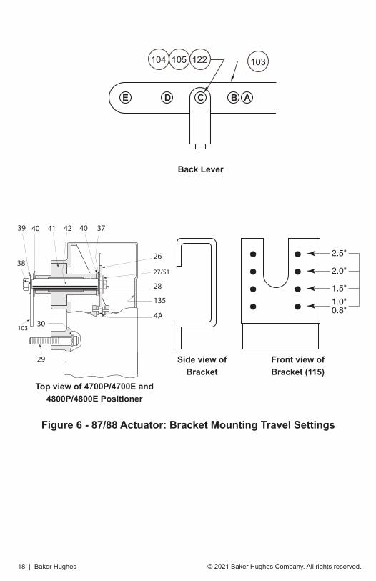
Mounting 4700P and 4700E on Series 87/88 Actuators1. Using screws (113) and lockwashers (114), mount bracket (115) on actuator with
opening located to the right side of the bracket (Air to Open).
2. Install input shaft (42) in post hub with a washer (40) on each side of the hub and retaining ring (37) on cam end.
3. Mount back lever (103) to input shaft using screw (38) and lockwasher (39).
4. Install clevis (102), clevis pin (104), washer (122), and retaining clip (105) in the proper location on the back lever. Location is based on valve stroke required.
5. Check Figure 6 for proper mounting location for positioner on bracket.
6. Mount positioner on bracket using socket head screws (29) and lockwashers (30).
NOTEBack lever must be behind bracket.
7. Mount cam (26) on input shaft using washer (27), lockwasher (51) and screw (28) with desired lobe against cam follower. (Do not mount cam if positioner is reverse action).
8. Connect turnbuckle (106), locknut (107), turnbuckle screw (101), locknut (108), and clamp rod (100).
Model Travel (mm) Travel (in.) Hole Location
4700 20.3 .8 A
4700 25.4 1.0 B
4700/4800 38.1 1.5 C
4700/4800 50.8 2.0 D
4700/4800 63.5 2.5 E
NOTEStrokes shorter than 20.3 mm (0.8”), require a special mounting kit. Consult with the factory for information.
© 2021 Baker Hughes Company. All rights reserved.18 | Baker Hughes
Figure 6 - 87/88 Actuator: Bracket Mounting Travel Settings
39
38
30
29
42 3740
28
26
4A
4140
135
27/51
103
2.5"
2.0"
1.5"
1.0"0.8"
Back Lever
Top view of 4700P/4700E and 4800P/4800E Positioner
Side view of Bracket
Front view of Bracket (115)
E D C B A
105104 122 103

Masoneilan 4700P/E & 4800P/E Positioners Manual | 19© 2021 Baker Hughes Company. All rights reserved.
Positioner Mounting and OrientationCamflexTM II, V-MaxTM, MiniTorkTM II, and ButterflyThe positioner is mounted to an intermediate plate (171) by two screws (29) and lockwashers (30) with the gauges nearest the actuator on Camflex (Figure 7) and with gauges away from actuator on MiniTork II (Figure 8), and HPBV 39004 (Figure 9). The intermediate mounting plate (171) is held by two flat-head screws (172) to the bracket.
NOTEThe cam take-off hole must be centered about the shaft.
Table 2 - Mounting Parts ReferenceRef. No.
Description Ref. No.
Description
29 Socket Head Screw 172 Mounting Plate Screws
171 Mounting Plate 30 Lockwashers
NOTEThe remainder of the mounting kit parts are used to before tightening mounting screws. assemble the cam to the actuator. See“Mounting Cam Coupling” on page 34.

© 2021 Baker Hughes Company. All rights reserved.20 | Baker Hughes
Figure 7 - Camflex II
Figure 8 - MiniTork II For detail of Positioner Mounting Parts, see Figure 7
Figure 9 - 39000 Series High Performance Butterfly Valve For detail of Positioner Mounting Parts, see Figure 7

Masoneilan 4700P/E & 4800P/E Positioners Manual | 21© 2021 Baker Hughes Company. All rights reserved.
Pneumatic InstallationNOTE
The output and supply connections for the 4700E/P and 4800E/P are different from those on the 4600A.“Mounting Cam Coupling” on page 34.
These positioners are designed to operate only with clean, dry, oil-free, instrument grade air to ASME/ASA-57.3 1975 (R1981) or ISA-S7.3-1075 (R1981).
Dew point At least 18 °F (10 °C) below minimum anticipated ambient temperature
Particulate matter Filtered to below 5 microns
Oil content Less than 1 ppm w/w or v/v
Contaminants Free of all corrosive contaminants and hazardous gases, flammable or toxic
The signal connections of 4700P and 4800P and the output and supply connections of 4700P and 4700E are tapped 1/4” NPT. The output and supply connections of 4800P and 4800E are tapped 3/8” NPT. There is also an exhaust connection with a plastic square head plug in it. If the action of the positioner is reversed, 4700P/4800P only, then the supply and exhaust connections must be interchanged. With reverse action, the Supply gauge must be removed and replaced by an 1/8” NPT plug installed in the supply connection. Since the new supply connection has no gauge port, connect the removed Supply gauge to the filter regulator to indicate regulator output pressure.Figure 10 on page 23 shows pneumatic connections for both the 4700P/4800P and 4700E/4800E positioners. The 4700E/4800E has the Instrument port sealed by a 1/4” NPT Plug; do not remove plug or make any other connections to this port.

© 2021 Baker Hughes Company. All rights reserved.22 | Baker Hughes
The use of a filter regulator with a 5 micron filter is recommended for the air supply. Tubing used for piping between filter regulator, positioner, and actuator should be 1/4” minimum, with 3/8” used for larger actuators with 4700P/4800E positioner.
WARNINGNever exceed actuator or positioner maximum supply pressure. Damage to equipment or injury to personnel may result.
CAUTIONDo not use pipe thread sealant tapes on pneumatic fittings, as it tends to shred small particles which can cause instrument malfunction.
The use of soft setting anaerobic hydraulic seal, such as Loctite Hydraulic Seal 542, is recommended. Follow manufacturer’s instructions.
CAUTIONDo not use an excessive amount, as it will not set and may migrate into the instrument.
The pneumatic input signal ranges are 3-15 psig (20-100 kPa or 207- 1034 mbar), 6-30 psig (40-200 kPa or 414-2068 mbar), and 3-27 psig (20-180 kPa or 207-1862 mbar). Split ranges are available.
Positioners with 24 psig signal span (i.e., 6-30 psig and 3-27 psig) require a different diaphragm assembly as shown in Figure 18 on page 56.
Maximum allowable air supply pressure to the positioner varies according to actuator, valve size, and type. See pressure drop tables in valve catalog to determine correct positioner supply pressure.

Masoneilan 4700P/E & 4800P/E Positioners Manual | 23© 2021 Baker Hughes Company. All rights reserved.
Figure 10 - Pneumatic Installation

© 2021 Baker Hughes Company. All rights reserved.24 | Baker Hughes
Electrical Installation of 4700E/4800EElectrical connections should be made as shown in Figure 11. The terminals will accept wire sizes up to AWG 14.The loop controller driving the positioner must be capable of supplying 4-20 mA with an output voltage compliance of at least 5 VDC.The available output voltage of a current source is reduced by loop wiring resistance. This can be checked by connecting a resistor of value (250 Ohms + Loop Resistance) across the output of the controller and verifying that at 100% controller output 20 mA is obtainable.
CAUTIONDo not use a voltage source to drive the positioner as it may cause permanent damage.
CAUTIONThe positioner must be installed in accordance with local and national codes of practice in both general purpose and hazardous area locations. The electrical components are fully isolated from ground and therefore grounding is unnecessary for functional purposes. Grounding may be necessary to conform to installation codes.
The positioner is normally supplied with a 1/2” NPT conduit entry. (M20 is optional) Internal and external ground terminals are provided for use if grounding is required.
Figure 11 - Electrical Connections

Masoneilan 4700P/E & 4800P/E Positioners Manual | 25© 2021 Baker Hughes Company. All rights reserved.
Hazardous Area InstallationsThe positioner is available in versions suitable for use in hazardous areas. The labeling on the positioner indicates correct areas of use.
WARNINGInstallation of any hazardous area equipment must be made in accordance with the appropriate hazardous area installation codes and the manufacturer’s installation and operating instructions. You must make no changes or attempt any repairs of a certified instrument since this invalidates the certified design. If a certified instrument should fail it must be returned to the manufacturer for repair.
Maximum pressure 100 psi.
WARNINGUnder certain circumstances, non-metallic parts may generate an ignition-capable level of electrostatic charge. To avoid the risk from electrostatic discharge and safe operation, a damp cloth shall only be used when cleaning or wiping the device. Cleaning must only be done when local conditions around the device are free of potentially explosive atmospheres. Do not use a dry cloth or any solvents.

© 2021 Baker Hughes Company. All rights reserved.26 | Baker Hughes
Substitution of components may impair intrinsic safety.
Explosion proof: Class I, Division 1, Groups B, C, and D. Temperature classification T6 @ 75°C ambient, T5 @ 85°C ambient, indoor and outdoor (NEMA Type 4X) hazardous (classified) locations.
12 V ≤ Vmax ≤ 30 V, Imax = 96 mA, Ci = 0 µF, Li = 3.7 mH
Do not open when an explosive gas atmosphere is present.
Dust-Ignition proof:
Class II / III, Division 1, Groups E, F, and G.
Temperature classification: T6 @ 75°C ambient, T5 @ 85°C ambient.
Max. power = 0.8 W. Ambient temperature: -40°C to +85°C.
Install as per drawing 97-055 (Figure 21 on page 62).
Non-Incendive: Class I, Division 2 Groups A, B, C, and D; S: Class II and III, Division 2 Groups F and G.
Temperature classification: T4 @ 40°C ambient, T3B @ 70°C ambient, T3A @ 85°C ambient.
Installation must be in accordance with the current edition of the National Electrical Code ASME / NFPA-70, any applicable local codes, and manufacturer’s instructions.
Intrinsically Safe: Class I / II / III, Division 1, Groups A, B, C, D, E, F, and G hazardous indoor/outdoor NEMA 4X locations.
Temperature Classification T4 @ 40°C ambient, T3B @ 70°C ambient, T3A @ 85°C ambient.
Installation must be in accordance with the current edition of the National Electrical Code ASME / NFPA-70, ASME / ISA RP 12.6 “Installation of Intrinsically Safe Instrument Systems in Class I Hazardous (Classified) Locations”, Figure 12 on page 30, and manufacturer’s instructions.
WARNING
WARNING
FM (Factory Mutual) Approved Version

Masoneilan 4700P/E & 4800P/E Positioners Manual | 27© 2021 Baker Hughes Company. All rights reserved.
CSA (Canadian Standards Association) Approved Version
Substitution of components may impair intrinsic safety/Div 2 suitability.
Explosion proof: Class I, Division 1, Groups B, C, and D Class II, Groups E, F, and G and Class III rated at 30 mA maximum, 28 VDC maximum, with a temperature code T6 @ 75°C, T5 @ 85°C, Type 4X enclosure.
Non-Incendive: Class 1, Division 2, Groups A, B, C, and D, with a temperature code T6 @ 75°C, T5 @ 85°C.
Install as per drawing 97-055 (Figure 21 on page 62).
Installation must be in accordance with the current edition of the Canadian National Electrical Code Part I, any applicable local codes and manufacturer’s instructions.
Intrinsically Safe: Class I, Division 1, Groups A, B, C, and D, Class II, Groups E, F, and G, Class III rated at 30 mA maximum 28 VDC maximum. Temperature code T6 @ 55°C, T4A @ 85°C, Type 4X enclosure. Installation must be in accordance with the current edition of the Canadian National Electrical Code Part I, Figure 13 on page 31, and manufacturer’s instructions.
WARNING

© 2021 Baker Hughes Company. All rights reserved.28 | Baker Hughes
SIRA Approved Version
Installation must be in accordance with current applicable country codes and manufacturer’s instructions.
Maximum pressure 100 psi.
Intrinsically Safe:Installation must be in accordance with current editions of applicable country codes, Figure 14 on page 32, and manufacturer’s instructions. Housing protection rating IP 66.
Do not open when energized. Do not open when an explosive gas atmosphere is present. Use cables rated to ≥ 5°C above ambient.
For flameproof (Ex d protection concept):
The marking of the equipment shall include the following:ITS19ATEX15058X
II 2GD
Ex db h IIC T6 Gb Ta = -40°C to +55°C
Ex db h IIC T5 Gb Ta = -40°C to +70°C
Ex db h IIC T4 Gb Ta = -40°C to +85°C
Ex tb IIIC T90° Db Ta = -40°C to +55°C
WARNING

Masoneilan 4700P/E & 4800P/E Positioners Manual | 29© 2021 Baker Hughes Company. All rights reserved.
For intrinsically safe (Ex ia protection concept):
The marking of the equipment shall include the following:
ITS19ATEX15058X
II 1GD
Ex ia h IIC T4 GaEx ia h IIC T6 GaEx ia h IIIC Da T90°C
Ta = -40°C to +80°C, Pi = 1.1 WTa = -40°C to +55°C, Pi = 0.33 WTa = -40°C to +80°C, Pi = 1.1 W
Special Conditions for Safe Use (denoted by X after the certificate number)
This enclosure is made from light metal which could cause ignition due to impact. This shall be taken into consideration when the apparatus is installed in locations that specifically require Equipment Protection Levels Ga or Da.
If the Model 4000 I/P Converter is mounted with the axis of the plastic baffle in the vertical position with the baffle uppermost, the required ingress protection against water is invalidated; therefore, it shall only be installed in this orien-tation if its location provides protection against falling water.

© 2021 Baker Hughes Company. All rights reserved.30 | Baker Hughes
Figure 12 - FM Installation

Masoneilan 4700P/E & 4800P/E Positioners Manual | 31© 2021 Baker Hughes Company. All rights reserved.
Figure 13 - CSA Installation

© 2021 Baker Hughes Company. All rights reserved.32 | Baker Hughes
Figure 14 - ATEX Installation

Masoneilan 4700P/E & 4800P/E Positioners Manual | 33© 2021 Baker Hughes Company. All rights reserved.
Split Range OperationSplit ranging permits operation of two valves in sequence from one 4-20 mA control signal. To accomplish this with the 4700E/4800E, the two positioners are connected in series as shown in Figure 15, with the actual split ranging done by proper cam segment selection per tables in “Cam Lobe Selection and Lever Arm Orientation” on page 53.
NOTEWith this configuration, the voltage burden of the 4-20 mA controller is 10 V instead of 5 V.
Figure 15 - Split Range
© 2021 Baker Hughes Company. All rights reserved.34 | Baker Hughes
Mounting Cam CouplingSee Figure 18 (page 56) and 19 (page 58).
The cam coupling (34), used on rotary actuators, is positioned on the shaft with the key engaged in the shaft slot and the set screws (35) to the top and side. The coupling hold-down screw (32) with the lockwasher (33) is torqued to 125 inch-lbs.
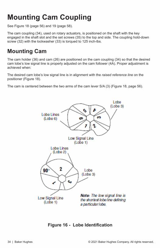
Mounting CamThe cam holder (36) and cam (26) are positioned on the cam coupling (34) so that the desired cam lobe’s low signal line is properly adjusted on the cam follower (4A). Proper adjustment is achieved when:
The desired cam lobe’s low signal line is in alignment with the raised reference line on the positioner (Figure 18).
The cam is centered between the two arms of the cam lever S/A (3) (Figure 18, page 56).
Figure 16 - Lobe Identification

Masoneilan 4700P/E & 4800P/E Positioners Manual | 35© 2021 Baker Hughes Company. All rights reserved.
Lever S/A OrientationSee “Field Mounting and Complete Calibration, Rotary Actuators” on page 40 and “Field Mounting and Complete Calibration Reciprocating Valves using 87/88 Actuators” on page 43).
The relative position of the lever S/A (3) for a selected cam lobe must be correct. The lever S/A can be mounted with its pivot post to the left or right of the cam center.
Changing Lever S/A OrientationSee “Field Mounting and Complete Calibration, Rotary Actuators” on page 54 and “Field Mounting and Complete Calibration Reciprocating Valves using 87/88 Actuators” on page 43).
If lever S/A (3) must be changed, remove screw (28), lockwasher (51) and washer (27), and cam (26) from cam shaft. Remove retaining ring (17) and flat washer (16). Remove lever S/A (3) from pivot post. Lift and rotate lever S/A (3) on spring end 180° to desired position. (Do not rotate spring end; socket head screw on spring must face outward.) Replace flat washer (16) and retaining ring (17) on pivot post.

© 2021 Baker Hughes Company. All rights reserved.36 | Baker Hughes
CalibrationGeneral
WARNINGBefore commencing any calibration or maintenance procedure on these positioners, ensure that the valves under control are isolated from the controlled process and that the area is verified as nonhazardous.
The Model 4700P/4700E and 4800P/4800E positioner, when factory mounted, has been calibrated for the proper valve, valve action, and positioner action. If, for any reason, the cam holder (36) setting has been disturbed (i.e., a change of positioner action, field mounting, maintenance, etc.), it is necessary to follow all steps of the calibration instructions, according to desired actuator action and positioner action.
For proper performance when the valve is installed, calibrate the positioner as part of the normal installation procedure. Shipping, handling and installation can cause some changes in the calibration.
Calibration may entail just a simple adjustment or a complete field mount. Define the scope of work and follow the applicable sections.
CAUTIONDo not attempt to remove cam if cam is not at low signal line of lobe (low end of range). Refer to calibration instruction for proper valve action and positioner action before removing or replacing cam and tightening set screws (35) to proper torque.

Masoneilan 4700P/E & 4800P/E Positioners Manual | 37© 2021 Baker Hughes Company. All rights reserved.
Zero Adjustment See Figure 18 (page 56) and Figure 19 (page 58).
The zero adjustment is made with the zero nut (4B). When the positioner is installed and the pneumatic circuits are connected apply low instrument signal (i.e., 3 psi for 4700P/4800P, 4 mA for 4700E/4800E), release locknut (4C) and turn zero nut (4B) to adjust valve plug to proper position (open or closed). Then tighten zero lock nut (4C).
NOTEDo not attempt to adjust zero nut with signal above low end of signal range. If valve is seated at low end of signal range, after making zero adjustment, decrease signal below low end of signal range and slowly increase signal to ensure valve plug lifts off seat at desired signal. If valve is open at low end of signal range, adjust zero so valve indicates Open on travel indicator scale.
Span AdjustmentSee Figure 18 (page 56) and Figure 19 (page 58).
If the valve does not fully stroke for a full signal span, the feedback spring rate is too high. Loosen screw (8) and turn spring (5) on the spring end (4) to increase the number of active coils and decrease the spring rate. Conversely, if full stroke is reached prior to full signal span, turn the spring to decrease the number of active coils and increase the spring rate.
Adjustment of +1/4 turn of the spring changes its rate by approximately +10%.
After making a spring adjustment, it is necessary to reset the zero. This is done by turning the zero adjustment (4B), and tightening zero locknut (4C).
Example: If the number of active coils is increased making the spring longer, it is necessary to readjust the zero nut to compensate for the increased spring length.
When span adjustment has been completed, re-tighten the spring locking socket head screw (8).
CAUTIONWhen installing positioner with cam in place, check the position of the spring (5) on diaphragm S/A (9) to ensure that it is centered on the diaphragm.

© 2021 Baker Hughes Company. All rights reserved.38 | Baker Hughes
Cam Lobe ChangeIf it is necessary to change the cam lobe only (without changing actuator action or positioner action) then proceed as follows:
CAUTIONIf cam is not at low signal line on lobe (low end of range), do not attempt to remove cam. The cam must be at low signal line. Select correct actuator and positioner action and proceed as follows.
NOTEDo not disturb cam holder (36) setting on rotary actuators. [i.e. do not touch set screws (35)].
Air to Open / Direct Acting PositionerSee Figure 18 (page 56) and Figure 19 (page 58).
1. Shut off supply pressure and signal to positioner. Valve is now closed and cam (26) is at low signal line on lobe.
2. With cam at low signal line remove screw (28), lockwasher (51) and washer (27). Note the relative position of the cam lobe being changed and then remove the cam (26).
3. Select the desired cam lobe and replace cam (26) on cam shaft with low signal line of desired lobe against cam follower. Ensure the newly selected cam lobe is in the same relative position as the lobe noted in Step 2.
4. Replace washer (27), lockwasher (51) and screw (28). Turn on supply pressure and signal to positioner. Check zero and span adjustment. Refer to “Zero Adjustment” and Span Adjustment37.
Air to Open / Reverse Acting PositionerSee Figure 18.
1. Shut off supply pressure and signal to positioner. Valve is now closed and cam (26) is at high signal line on lobe. Do not remove.
2. Run an independent regulated air line to the valve actuator in place of positioner output line. Slowly apply proper air pressure through the regulator to open the valve. Do not exceed designated supply pressure. (Handwheel may be used to open the valve in place of regulated air line). Align the travel indicator with the open end of travel scale. Do not over travel. Cam is now at low signal line on lobe.
3. With cam at low signal line remove screw (28), lockwasher (51) and washer (27). Note the relative position of the cam lobe being changed and then remove the cam (26).

Masoneilan 4700P/E & 4800P/E Positioners Manual | 39© 2021 Baker Hughes Company. All rights reserved.
4. Select the desired cam lobe and replace cam (26) on cam shaft with low signal line of desired lobe against cam follower. Ensure that the newly selected cam lobe is in the same relative position as the lobe in Step 3.
5. Replace washer (27), lockwasher (51) and screw (28). Reduce pressure applied in Step 2 to zero (back off the handwheel if handwheel was used). Disconnect the independent regulated air line to actuator and connect positioner output line. Connect supply pressure and signal to positioner. Check zero and span adjustment. Refer to and “Span Adjustment” on page 37.
Air to Close / Direct Acting PositionerSee Figure 18 (page 56) and Figure 19 (page 58).
1. Shut off supply pressure and signal to positioner. Valve is now open and cam (26) is at low signal line on lobe.
2. With cam at low signal line remove screw (28), lockwasher (51) and washer (27). Note the relative position of the cam lobe being changed and then remove the cam (26).
3. Select the desired cam lobe and replace cam (26) on cam shaft with low signal line of desired lobe against cam follower. Ensure the newly selected cam lobe is in the same relative position as the lobe noted in Step 2.
4. Replace washer (27), lockwasher (51) and screw (28). Check zero and span adjustment. Refer to “Zero Adjustment” and “Span Adjustment” on page 37.
Air to Close / Reverse Acting PositionerSee Figure 18.
1. Shut off supply pressure and signal to positioner. Valve is now open and cam (26) is at high signal line on lobe. Do not remove.
2. Run an independent regulated air line to the valve actuator in place of positioner output line. Slowly apply proper air pressure through the regulator to shut the valve. Do not exceed designated supply pressure. (Handwheel may be used to close the valve in place of regulated air line.) Align the travel indicator with the closed end of travel scale. Cam is now at low signal line on lobe.
3. With cam at low signal line remove screw (28), lockwasher (51) and washer (27). Note the relative position of the cam lobe being changed and then remove the cam (26).
4. Select the desired cam lobe and replace cam (26) on cam shaft with low signal line of desired lobe against cam follower (4A). Ensure the newly selected cam lobe is in the same relative position as the lobe noted in Step 3.
5. Replace washer (27), lockwasher (51) and screw (28). Reduce pressure applied in Step 2 to zero (back off the handwheel if handwheel was used). Disconnect the independent regulated air line to actuator and connect positioner output line. Connect supply pressure and signal to positioner. Check zero and span adjustment. Refer to “Zero Adjustment” and “Span Adjustment” on page 37.

© 2021 Baker Hughes Company. All rights reserved.40 | Baker Hughes
Field Mounting and Complete Calibration, Rotary ActuatorsThe following instructions are to be followed for mounting and calibration of the 4700P/4700E and 4800P/4800E positioner. Define the proper valve action and positioner action. If the positioner is not on the valve, see Figure 19 on page 58 to mount positioner and cam coupling. Once the positioner body is assembled on the valve and the coupling is on the valve shaft, proceed to the proper section below.
Air to Open / Direct Acting PositionerSee Figure 18 (page 56) and Figure 19 (page 58).
1. Do not connect air supply or signal to the positioner. Valve is closed.
2. Place lever S/A (3) to proper side (left or right) as designated by the appropriate cam selection table for valve in question.
3. With valve closed, place cam holder (36) with Truarc ring (37) into cam coupling (34).
4. Place the cam (26) onto the cam holder (36) so that the selected cam lobe is facing forward and will rest on the cam follower. (See appropriate table for cam selection.) Secure cam to cam holder with washer (27), lockwasher (51) and screw (28). Tighten the screw (28) while holding the cam (26).
5. With the valve closed, place the desired cam lobe’s low signal line on the cam follower (4A). With the low signal line resting on the cam follower, sight across the face of the cam to the raised reference line on the positioner case and align. (Low signal line and reference line.) Center cam between the two arms of the lever S/A (3), then tighten set screws (35) to 87 inch-lbs torque. (See Figure 18 on page 56 for cam mounting.)
6. Connect air supply and signal to positioner. Connect positioner output to valve actuator. Refer to connection diagram. Adjust signal to low end of signal (i.e., 3 psig for a 3-15 psig range 4700P/4800P; 4 mA for 4-20 mA 4700E/4800E).
7. Adjust zero and span. Refer to “Zero Adjustment” and “Span Adjustment” on page 37.
Air to Open / Reverse Acting PositionerSee Figure 18.
1. Do not connect air supply or signal to the positioner. Valve is closed.
2. Place lever S/A (3) to proper side (left or right) as designated by the appropriate cam selection table for valve in question.
3. Run an independent regulated air line to the valve actuator in place of positioner output line. Slowly apply proper air pressure through the regulator to open the valve. (Handwheel may be used to open the valve in place of regulated air line.) Align the travel indicator with the open end of travel scale. Do not over travel.
4. Place cam holder (36) with truarc ring (37) into cam coupling (34).
5. Place the cam (26) onto the cam holder (36) so that the selected cam lobe is facing

Masoneilan 4700P/E & 4800P/E Positioners Manual | 41© 2021 Baker Hughes Company. All rights reserved.
forward and will rest on the cam follower. See appropriate table for cam selection. Secure cam (26) to cam holder (36) with washer (27), lockwasher (51) and screw (28). Tighten screw (28) while holding the cam (26).
6. With the valve open, place the desired cam lobe’s low signal line on the cam follower (4A). With the low signal line resting on the cam follower sight across the face of the cam to the raised reference line on the positioner case and align. (Low signal line and reference line.) Center cam between the two arms of the lever S/A (3) then tighten set screws (35) to 87 inch-lbs. torque. (See Figure 18 on page 56 for cam mounting.)
7. Slowly reduce pressure applied to actuator in Step 3 to zero. (If handwheel was used to place valve in open position, back it off completely.) Cam is at high signal line on lobe.
8. Disconnect the independent regulated air line to actuator and connect positioner output line. Connect supply pressure and signal to positioner.
9. Adjust signal to low end of signal (i.e., 3 psig for a 3-15 psig range 4700P/4800P). Adjust zero and span. Refer to “Zero Adjustment” and “Span Adjustment” on page 37.
Air to Close / Direct Acting PositionerSee Figure 18 (page 56) and Figure 19 (page 58).
1. Do not connect air supply or signal to the positioner. Valve is now open.
2. Note the valve position. The travel indicator should be approximately aligned with the open end of the travel scale. If not aligned, consult proper valve instruction for travel adjustment.
3. With valve open, place lever S/A (3) to proper side (left or right) as designated by the appropriate cam selection table for valve in question.
4. With valve open, place cam holder (36) with truarc ring (37) into cam coupling (34).
5. Place the cam (26) onto the cam holder (36) so that the selected cam lobe is facing forward and will rest on the cam follower. Secure cam to cam holder with washer (27), lockwasher (51) and screw (28). Tighten screw (28) while holding the cam (26).
6. With the valve open, place the desired cam lobe’s low signal line on the cam follower. With the low signal line resting on the cam follower sight across the face of the cam to the raised reference line on the positioner case and align. (Low signal and reference line.) Center cam between the two arms of the lever S/A (3), then tighten set screws (35) to 87 inch-lbs. torque. (See Figure 18 on page 56 for cam mounting.)
7. Connect air supply and signal to positioner. Connect positioner output to valve actuator. Refer to connection diagram for valve in question. Adjust signal to low end of signal (i.e., 3 psig for a 3-15 psig range 4700P/4800P; 4 mA for 4-20 mA 4700E/4800E). Adjust zero and span. Refer to “Zero Adjustment” and “Span Adjustment” on page 37.

© 2021 Baker Hughes Company. All rights reserved.42 | Baker Hughes
Air to Close / Reverse Acting PositionerSee Figure 18.
1. Do not connect air supply or signal to the positioner. Valve is now open.
2. Note the valve position. The travel indicator should be approximately aligned with the open end of the travel scale. If not aligned, consult proper valve instructions for travel adjustment.
3. Place lever S/A (3) to proper side (left or right) as designated by the appropriate cam selection table for valve in question.
4. Run an independent regulated air line to the valve actuator in place of positioner output line. Slowly apply proper air pressure through the regulator to shut the valve. Do not exceed designated supply pressure. (Handwheel may be used to close the valve in place of regulated air line.)
5. With valve closed, place cam holder (36) with truarc ring (37) into cam coupling (34).
6. Place the cam (26) into the cam holder (36) so that the selected cam lobe is facing forward and will rest on the cam follower. Secure cam to cam holder with washer (27), lockwasher (51) and screw (28). Tighten screw (28) while holding the cam (26).
7. With the valve closed, place the desired cam lobe’s low signal line on the cam follower. With the low signal line resting on the cam follower sight across the face of the cam to the raised reference line on the positioner case and align. (Low signal line and reference line.) Center cam between the two arms of the lever S/A (3), then tighten set screws (35) to 87 inch-lbs. torque. (See Figure 18 on page 56 for cam mounting.)
8. Slowly reduce pressure applied to actuator in Step 4 to zero. (If handwheel was used to place valve in closed position, back it off completely.) Valve is now open. Cam is at high signal line on lobe.
9. Disconnect the independent regulated air line to actuator and connect positioner output line. Connect supply pressure and signal to positioner.
10. Adjust signal to low end of signal (i.e., 3 psig for a 3-15 psig range 4700P/4800P). Adjust zero and span. Refer to “Zero Adjustment” and “Span Adjustment” on page 37.

Masoneilan 4700P/E & 4800P/E Positioners Manual | 43© 2021 Baker Hughes Company. All rights reserved.
Field Mounting and Complete Calibration Reciprocating Valves using 87/88 Actuators Define valve action and positioner action. (4700E/4800E is direct action only) If lever S/A (3) is not on proper side (Left or Right) as determined from data from “Cam Lobe Selection and Lever Arm Orientation” on page 53, change to correct position. Refer to “Changing Lever S/A Orientation” on page 35. If positioner is not on valve refer to Figure 5 on page 16 through Figure 9 on page 20 for mounting and linkage connection procedures. If positioner is reverse acting (4700P/4800P only) do not assemble cam to shaft at this time. Make pneumatic connections per Figure 10 on page 23 for action desired (4700P/4800P), or electrical and pneumatic connections for 4700E/4800E (direct action only). Proceed to proper section below.
Air to Open / Direct Acting Positioner See Figure 18 (page 56) and Figure 19 (page 58).
1. Apply lower value of instrument signal. (i.e. 3 psi if 3-15 psi 4700P/4800P or 4 mA if 4-20 mA 4700E/4800E).
2. Unlock zero locknut (4C) and turnbuckle locknut (107). Adjust zero by turning both the zero nut (4B) and turnbuckle (106) until the low signal line of the cam is aligned with the positioner case raised reference line and the travel indicator shows closed position. Retighten both locknuts.
3. Apply full scale value of instrument signal (i.e. 15 psi or 20 mA.) and note position of travel indicator. If travel is not correct, perform span adjustment. Refer to “Span Adjustment” on page 37.
4. Repeat zero and span adjustments per “Zero Adjustment” and “Span Adjustment” on page 37 until travel range is correct. After adjustments are satisfactory, re-tighten the spring locking screw (8), zero locknut (4C), and turnbuckle locknut (107).
Air to Open / Reverse Acting Positioner (4700P/4800P only) Figure 18.
1. Disconnect air line from positioner to actuator at actuator. Run an independent regulated air line to the actuator. Slowly apply proper air pressure through the regulator to open the valve. (Handwheel may be used to open valve instead of regulated air line.) Align the travel indicator with the open end of travel scale. Do not overtravel.
2. Place cam (26) on to cam shaft with selected cam lobe facing forward and low signal line approximately aligned with positioner case raised reference line. Secure cam to shaft using washer (27), lockwasher (51) and screw (28).
3. Slowly reduce pressure applied to actuator to zero (If handwheel was used, back if off fully). Cam will now be at high signal line.

© 2021 Baker Hughes Company. All rights reserved.44 | Baker Hughes
4. Disconnect the independent regulated air line and connect the positioner output line to the actuator. Connect supply pressure and signal to the positioner.
5. Apply low value of instrument signal. (3 psi if 3-15 psi signal range) Unlock zero locknut (4C) and turnbuckle locknut (107). Adjust zero by turning both the zero nut (4B) and turnbuckle (106) until the low signal line of the cam is aligned with the positioner case raised reference line and the travel indicator shows opened position. Refer to Figure 5 on page 16 and Figure 18 on page 56. Re-tighten both locknuts.
6. Apply full scale value of instrument signal (i.e. 15 psi) and note position of stroke scale indicator. If travel is not correct, perform span adjustment. Refer to “Span Adjustment” on page 37.
7. Repeat zero and span adjustments per “Zero Adjustment” and “Span Adjustment” on page 37 until travel range is correct. After adjustments are satisfactory, re-tighten the spring locking screw (8), zero locknut (4C), and turnbuckle locknut (107).
Air to Close / Direct Acting PositionerSee Figure 18 (page 56) and Figure 19 (page 58).
1. Apply lower value of instrument signal (i.e. 3 psi if 3-15 psi 4700P/4800P or 4 mA if 4-20 mA 4700E/4800E).
2. Unlock zero locknut (4C) and turnbuckle locknut (107). Adjust zero by turning both the zero nut (4B) and turnbuckle (106) until the low signal line of the cam is aligned with the positioner case raised reference line and the travel indicator shows opened position. Refer to Figure 5 on page 16 and Figure 18 on page 56. Re-tighten both locknuts.
3. Apply full scale value of instrument signal (i.e. 15 psi or 20 mA.) and note position of travel indicator. If travel is not correct, perform span adjustment. Refer to “Span Adjustment” on page 37.
4. Repeat zero and span adjustments per “Zero Adjustment” and “Span Adjustment” on page 37 until travel range is correct. After adjustments are satisfactory, re-tighten the spring locking screw (8), zero locknut (4C), and turnbuckle locknut (107).
Air to Close/Reverse Acting Positioner (4700P/4800P only) See Figure 18.
1. Disconnect air line from positioner to actuator at actuator. Run an independent regulated air line to the actuator. Slowly apply proper air pressure through the regulator to close the valve. (Handwheel may be used to open valve instead of regulated air line.) Align the travel indicator with the closed end of travel scale. Do not overtravel.
2. Place cam (26) on to cam shaft with selected cam lobe facing forward and low signal line approximately aligned with positioner case raised reference line. Secure cam to shaft using washer (27), lockwasher (51) and screw (28).
3. Slowly reduce pressure applied to actuator to zero (If handwheel was used, back if off fully). Cam will now be at high signal line.

Masoneilan 4700P/E & 4800P/E Positioners Manual | 45© 2021 Baker Hughes Company. All rights reserved.
4. Disconnect the independent regulated air line and connect the positioner output line to the actuator. Connect supply pressure and signal to the positioner.
5. Apply low value of instrument signal. (3 psi if 3-15 psi signal range) Unlock zero locknut (4C) and turnbuckle locknut (107). Adjust zero by turning both the zero nut (4B) and turnbuckle (106) until the low signal line of the cam is aligned with the positioner case raised reference line and the travel indicator shows closed position. Refer to Figure 5 on page 16 and Figure 18 on page 56. Re-tighten both locknuts.
6. Apply full scale value of instrument signal (i.e. 15 psi) and note position of stroke scale indicator. If travel is not correct, perform span adjustment. Refer to “Span Adjustment” on page 37.
7. Repeat zero and span adjustments per “Zero Adjustment” and “Span Adjustment” on page 37 until travel range is correct. After adjustments are satisfactory, re-tighten the spring locking screw (8), zero locknut (4C), and turnbuckle locknut (107).
NOTEAlthough this procedure is written for 87/88 actuators, it is, in general, applicable to calibration of any reciprocating actuator.
Damping AdjustmentThe airflow to the actuator may be reduced by turning screw (20) clockwise. This adjustment may be required for smaller volume actuators if instability is observed. Turn clockwise until desired stability is obtained.
CAUTIONScrew must never be backed out further than top flush with housing.

© 2021 Baker Hughes Company. All rights reserved.46 | Baker Hughes
Positioner Action Change (4700P/4800P Only)Whenever it becomes necessary to change positioner action from direct to reverse or vice versa, it is important to be familiar with the following steps.
To remove or install the cam safely, the valve position must correspond to the low signal line on lobe.
The positioner supply line, the vent and the lever S/A must be reversed.
From Air to Open / Direct to Air to Open/Reverse1. Perform Steps 1 and 2 from Cam Lobe Change38 for Air to Open/Direct Acting Positioner.
Cam is now removed.
2. Proceed to Field Mounting and Calibration section for Air to Open/Reverse Acting Positioner and proceed as stated.
From Air to Open / Reverse to Air to Open/Direct1. Perform Steps 1, 2 and 3 from “Cam Lobe Change” on page 38 for Air to Open/Reverse
Positioner. Cam is now removed.
2. Slowly reduce pressure applied to actuator to zero. (If handwheel was used to place valve in open position back it off completely.) Valve is now closed. Remove independent regulated air line from actuator.
3. Proceed to Field Mounting and Calibration section for Air to Open/Direct Acting Positioner and proceed as stated.
From Air to Close / Direct to Air to Close/Reverse1. Perform Steps 1 and 2 from “Cam Lobe Change” on page 38 for Air to Close/Direct Acting
Positioner. Cam is now removed.
2. Proceed to Field Mounting and Calibration section for Air to Close/Reverse Acting Positioner and proceed as stated.
From Air to Close / Reverse to Air to Close/Direct1. Perform Steps 1, 2 and 3 from “Cam Lobe Change” on page 38 for Air to Close/Reverse
Acting Positioner. Cam is now removed.
2. Slowly reduce pressure applied to actuator to zero. (If handwheel was used to place valve in closed position back it off completely.) Valve is now open. Remove independent regulated air line from actuator.
3. Proceed to Field Mounting and Calibration section for Air to Close/Direct Acting Positioner and proceed as stated.

Masoneilan 4700P/E & 4800P/E Positioners Manual | 47© 2021 Baker Hughes Company. All rights reserved.
MaintenanceWARNING
Before commencing any calibration or maintenance procedure on these positioners, ensure that the valves under control are isolated from the controlled process and that the area is verified as nonhazardous.
PilotSee Figure 17.
To clean or replace deteriorated parts, the valve must be isolated from process. Shut off air supply. To minimize maintenance time, it is recommended that the entire pilot subassembly (11) be replaced by a new subassembly, so that the old unit can be worked on when time permits.
Disassembly1. Unscrew the pilot subassembly (11) and disengage it from the body (1). Note: Turn the
pilot subassembly while removing it to prevent damage to the O-rings.
2. Remove end plug and withdraw the spring, plug and extension pin. If necessary, use a penetrating oil to free parts.
CAUTIONDo not disassemble or adjust extension pin.
3. Wipe the parts with a clean soft lint free cloth and blow compressed air through the orifices. Use isopropyl alcohol to clean. Do not use chloride based solvents.
Reassembly1. Install three new O-rings on the pilot spool. Put a light coating of silicone grease on each
O-ring.
2. Replace the extension pin and the plug, countersunk end first into the pilot spool. The plug should slide into the pilot spool by its own weight.
3. Install the spring in the pilot spool. The end having the smallest diameter must be in contact with the plug. Screw the pilot end plug into the pilot spool.
4. Install the pilot subassembly (11) into the body (1).

© 2021 Baker Hughes Company. All rights reserved.48 | Baker Hughes
BodyShut off the air supply. Disconnect air lines, linkage if reciprocating, and electrical connections if 4700E/4800E. If positioner is reverse acting, refer to applicable section under “Cam Lobe Change” on page 38 to safely remove cam. Remove screw (28), washer (27), cam (26). Separate positioner from actuator by removing screws (29) and washers (30).
Disassembly See Figure 18 (page 56) and Figure 19 (page 58).
1. Remove pressure gauges (12) (13), and on 4700P/4800P only (14).
2. Remove the pilot subassembly (11).
3. Remove retaining ring (17), washer (16), lever S/A (3), and spring (5).
4. On 4700E/4800E only, remove 4 screws (21) to separate I/P module from body.
CAUTIONDo not damage or lose the three O-rings on bottom of module.
5. Remove cap screws (10) and separate body S/A from the case S/A.
6. Remove the diaphragm assembly (9), and reducer plate if 6-30 psi range 4700P/4800P.
7. Clean the body (1). Avoid the use of detergents that might deteriorate the diaphragm S/A. Use isopropyl alcohol. Do not use chloride-based solvents.
8. On 4700E/4800E, carefully remove the three O-rings from the bottom of the module. Inspect for any nicks or deterioration. Replace if necessary. Clean bottom of module using isopropyl alcohol. Carefully reassemble O-rings into grooves. Make sure they are seated in bottom of groove.
CAUTIONDo not use any lubrication on O-rings or base.
.

Masoneilan 4700P/E & 4800P/E Positioners Manual | 49© 2021 Baker Hughes Company. All rights reserved.
ReassemblySee Figure 18 (page 56) and Figure 19 (page 58).
1. Position the diaphragm assembly (9) on the case sub-assembly. If positioner is 6-30 psi range, install reducer plate per Figure 19. Secure the body subassembly to the case subassembly with cap screws (10). Tighten evenly to 60 inch-lbs of torque.
2. Replace spring (5), lever S/A (3), washer (16), and retaining ring (17).
3. On 4700E/4800E, carefully place module in position against body making sure that O-rings do not come out of grooves. Secure to body using screws (21).
4. Install the pilot assembly (11) and pressure gauges.
5. Install the positioner on the actuator. Reconnect air lines, electrical leads if 4700E/4800E, and coupling linkage if mounted on reciprocating valve.
6. Assemble cam to shaft per procedure under “Cam Lobe Change” on page 38. Recalibrate per appropriate Valve Action/Positioner Action calibration section.
DiaphragmIf the diaphragm has deteriorated, replace the diaphragm assembly. This requires separation of the body and case subassemblies as outlined under Disassembly48.
I/P ModuleReplacement of the I/P module requires removal of electrical connections, including conduit if used. Remove positioner from valve if module mounting screws are not accessible. Remove and replace module as outlined under “Disassembly” on page 48.
NOTEThere are no adjustments in the I/P module.

© 2021 Baker Hughes Company. All rights reserved.50 | Baker Hughes
Bypass Valve Option (4700P Only)See Figure 20 (page 60).
Assembly to Positioner Figure 20 (page 60).
It may be necessary to remove positioner from valve to assemble bypass.
1. Remove air connections, vent plug, and instrument gauge.
2. Clean surface of body and remove any thread sealant left in threaded ports.
3. Install O-rings (50) in each of the four recesses on the rear surface of the module (45), making sure they are seated in the bottom of the recess.
4. Assemble to positioner using four 8-32 x 1.25” long screws (21).
5. Reinstall vent plug, instrument gauge, and air connections.
Disassembly1. To remove from positioner, reverse assembly steps 5 and 4.
Do not use silicone grease on silicone O-rings.
2. To replace valve (48) O-ring seals, remove retaining ring (49) and slide valve out of block. Remove O-rings (46) and (47), replace with new rings which have a thin coat of KrytoxTM or other silicone-compatible lubricant. Replace valve in block and secure with retaining ring (49).
3. Reassemble bypass module to positioner.
Figure 17 - Pilot Assembly
NOTE

Masoneilan 4700P/E & 4800P/E Positioners Manual | 51© 2021 Baker Hughes Company. All rights reserved.
TroubleshootingThe following conditions must exist to ensure satisfactory operation of the positioner:
• The valve must be properly mounted in the line so that the actuator counters the dynamic torque and the valve operates as desired on air failure.
• Supply pressure is adequate for valve operation. See pressure drop tables in valve catalog.
• Correct positioner installation.
• Correct positioning of the feedback (cam, bearing lever, etc.).
• Proper cam selection.
• Supply, instrument signal and output connections must be correct for the positioner action (i.e., direct or reverse).
• Air tight connections.
• Correct position of the bypass.
In case of malfunction, check following in order given:
1. Check zero adjustment and adjust the zero nut (4B) if necessary. Lock with locknut (4C).
2. Check span adjustment and adjust if necessary.
3. Adjust instrument signal pressure from minimum to maximum and observe the corresponding gauge. If Instrument gauge reading does not respond to the signal, the diaphragm S/A may be broken. Replace the defective part.
4. Positioner insensitivity may be the result of a sticking pilot spool whose movement may be impeded by:
a. Foreign matter such as dirt, metal particles, etc.
b. Partial blockage of air passages caused by too much oil in the air lines.
c. Blocking of vent holes.

© 2021 Baker Hughes Company. All rights reserved.52 | Baker Hughes
Split Range Operation - 4700P/4800PSplit ranging permits the operation of two valves in sequence from one control instrument signal. The total stroking of each valve occurs with one half the signal (i.e., 3-9 psig or 9-15 psig). The following table shows, for example, the plug positions of two valves (both air to close action, open on air failure operating in split range) with a 3-15 psig instrument signal.
Table 3 - Split Range Operation
Instrument Signal Air Signal to Close No. 1
Valve Plug Position (3-9 psig)
Air Signal to Close No. 2
Valve Plug Position (9-15 psig)psig mbar
3 207 Full Open Full Open
6 414 Half Open Full Open
9 620 Closed Full Open
12 827 Closed Half Open
15 1034 Closed Closed
Masoneilan 4700P/E & 4800P/E Positioners Manual | 53© 2021 Baker Hughes Company. All rights reserved.
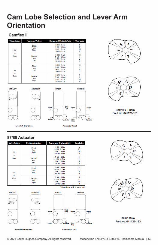
Cam Lobe Selection and Lever Arm OrientationCamflex II
87/88 Actuator

© 2021 Baker Hughes Company. All rights reserved.54 | Baker Hughes
Cam Lobe Selection and Lever Arm Orientation (Cont.)
MiniTork II (counter clockwise motion)
V-Max (clockwise motion)

Masoneilan 4700P/E & 4800P/E Positioners Manual | 55© 2021 Baker Hughes Company. All rights reserved.
Cam Lobe Selection and Lever Arm Orientation (Cont.)
Butterfly Valves (clockwise motion)

© 2021 Baker Hughes Company. All rights reserved.56 | Baker Hughes
Parts Reference 4700P/4800P 3-15 and 6-30 Range
Figure 18 - 4700P/4800P 3-15 and 6-30 Ranges
51
51

Masoneilan 4700P/E & 4800P/E Positioners Manual | 57© 2021 Baker Hughes Company. All rights reserved.
Table 4 - Parts Reference 4700P/4800P 3-15 and 6-30 Range
Ref. No. Description Ref. No. Description
1 Body S/A 26 Cam
2 Case S/A 27 Washer
3 Lever S/A 28 Pan Head Screw
4 Spring End 29 Socket Head Screw
4A Cam Follower 30 Lockwasher
4B Zero Nut 31 Gasket
4C Zero Lock Nut 32 Socket Head Screw
5 Spring, Feedback 33 Lockwasher
6 Clamp 34 Coupling
7 Lockwasher 35 Socket Head Set Screw
8 Socket Head Screw 36 Cam Holder
9 Diaphragm S/A 37 Truarc Ring
10 Screw 38 Cap Screw
11 Pilot S/A 39 Lockwasher
12 Supply Gauge 40 Washer
13 Output Gauge 41 Post Hub
14 Instrument Gauge 42 Input Shaft
15 Screw, Washer Head 51 Lockwasher
16 Washer
17 Retaining Clip
18 Cover, Case
19 Vent Plug
20 Screw, Sealing, Set 5/16-24 x .5
21 —
22 —
23 —
24 —
25 —

© 2021 Baker Hughes Company. All rights reserved.58 | Baker Hughes
Parts Reference 4700E/4800E
Figure 19 - 4700E/4800E
51
51

Masoneilan 4700P/E & 4800P/E Positioners Manual | 59© 2021 Baker Hughes Company. All rights reserved.
Table 5 - Parts Reference 4700E/4800E
Ref. No. Description Ref. No. Description
1 Body S/A 26 Cam
2 Case S/A 27 Washer
3 Lever S/A 28 Pan Head Screw
4 Spring End 29 Socket Head Screw
4A Cam Follower 30 Lockwasher
4B Zero Nut 31 Gasket
4C Zero Lock Nut 32 Socket Head Screw
5 Spring, Feedback 33 Lockwasher
6 Clamp 34 Coupling
7 Lockwasher 35 Socket Head Set Screw
8 Socket Head Screw 36 Cam Holder
9 3-15 Diaphragm S/A 37 Truarc Ring
10 Screw 38 Cap Screw
11 Pilot S/A 39 Lockwasher
12 Supply Gauge 40 Washer
13 Output Gauge 41 Post Hub
14 — 42 Input Shaft
15 — 43 Plug, Pipe 1/4” NPT
16 Washer 44 I/P Module Assembly
17 Retaining Clip 51 Lockwasher
18 Cover, Case
19 Vent Plug
20 Screw, Sealing, Set 5/16-24 x .5
21 Screw 8-32 x 1.25
22 O-ring .81” ID
23 O-ring 1.31” ID
24 O-ring 2.38” ID
25 Breather

© 2021 Baker Hughes Company. All rights reserved.60 | Baker Hughes
Parts ReferenceRef.No. Description
19 Vent Plug
21 Screw 8-32 x 1.25 SEMS
45 Bypass S/A
46 O-ring
47 O-ring
48 Valve, Bypass
49 Ring, Retaining
50 O-ring
Figure 20 - Bypass Option (4700P only)
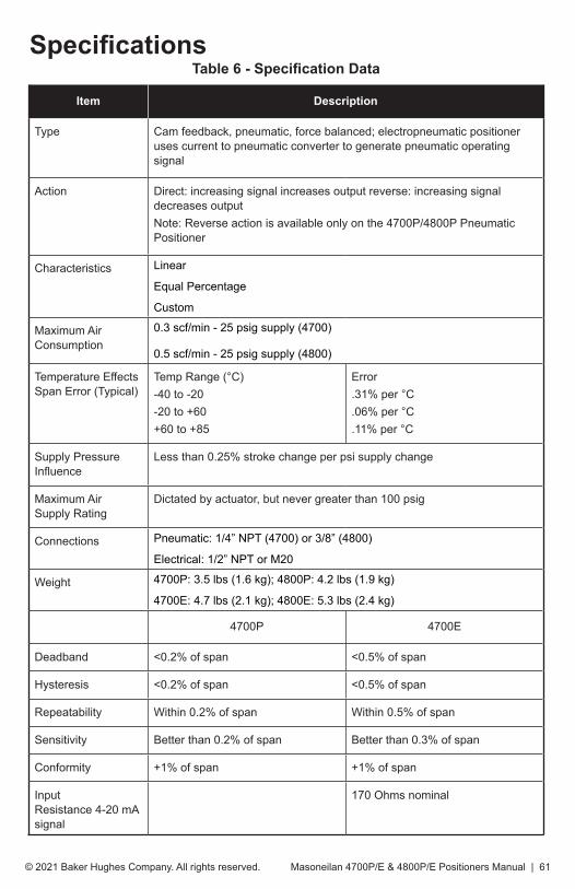
Masoneilan 4700P/E & 4800P/E Positioners Manual | 61© 2021 Baker Hughes Company. All rights reserved.
Table 6 - Specification Data
Item Description
Type Cam feedback, pneumatic, force balanced; electropneumatic positioner uses current to pneumatic converter to generate pneumatic operating signal
Action Direct: increasing signal increases output reverse: increasing signal decreases outputNote: Reverse action is available only on the 4700P/4800P Pneumatic Positioner
Characteristics Linear
Equal Percentage
Custom
Maximum Air Consumption
0.3 scf/min - 25 psig supply (4700)
0.5 scf/min - 25 psig supply (4800)
Temperature Effects Span Error (Typical)
Temp Range (°C)-40 to -20 -20 to +60+60 to +85
Error.31% per °C.06% per °C.11% per °C
Supply Pressure Influence
Less than 0.25% stroke change per psi supply change
Maximum Air Supply Rating
Dictated by actuator, but never greater than 100 psig
Connections Pneumatic: 1/4” NPT (4700) or 3/8” (4800)
Electrical: 1/2” NPT or M20
Weight 4700P: 3.5 lbs (1.6 kg); 4800P: 4.2 lbs (1.9 kg)
4700E: 4.7 lbs (2.1 kg); 4800E: 5.3 lbs (2.4 kg)
4700P 4700E
Deadband <0.2% of span <0.5% of span
Hysteresis <0.2% of span <0.5% of span
Repeatability Within 0.2% of span Within 0.5% of span
Sensitivity Better than 0.2% of span Better than 0.3% of span
Conformity +1% of span +1% of span
Input Resistance 4-20 mA signal
170 Ohms nominal
Specifications

© 2021 Baker Hughes Company. All rights reserved.62 | Baker Hughes
Drawings
Figure 21 - Positioner and Cast Body Assembly

Masoneilan 4700P/E & 4800P/E Positioners Manual | 63© 2021 Baker Hughes Company. All rights reserved.
NOTES:

© 2021 Baker Hughes Company. All rights reserved.64 | Baker Hughes
NOTES:

Masoneilan 4700P/E & 4800P/E Positioners Manual | 65© 2021 Baker Hughes Company. All rights reserved.
NOTES:

Tech Field Support & Warranty:Phone: +1-866-827-5378
Direct Sales Office LocationsAustraliaBrisbanePhone: +61-7-3001-4319
PerthPhone: +61-8-6595-7018
MelbournePhone: +61-3-8807-6002
BrazilPhone: +55-19-2104-6900
ChinaPhone: +86-10-5738-8888
FranceCourbevoiePhone: +33-1-4904-9000
IndiaMumbaiPhone: +91-22-8354790
New DelhiPhone: +91-11-2-6164175
ItalyPhone: +39-081-7892-111
JapanTokyo Phone: +81-03-6871-9008
KoreaPhone: +82-2-2274-0748
MalaysiaPhone: +60-3-2161-03228
MexicoPhone: +52-55-3640-5060
RussiaVeliky NovgorodPhone: +7-8162-55-7898
MoscowPhone: +7-495-585-1276
Saudi ArabiaPhone: +966-3-341-0278
SingaporePhone: +65-6861-6100
South AfricaPhone: +27-11-452-1550
South & Central America and the CaribbeanPhone: +55-12-2134-1201
SpainPhone: +34-935-877-605
United Arab EmiratesPhone: +971-4-8991-777
United KingdomPhone: +44-7919-382-156
United StatesHouston, TexasPhone: +1-713-966-3600
Find the nearest local Channel Partner in your area:valves.bakerhughes.com/contact-us
valves.bakerhughes.com
Copyright 2021 Baker Hughes Company. All rights reserved. Baker Hughes provides this information on an “as is” basis for general information purposes. Baker Hughes does not make any representation as to the accuracy or completeness of the information and makes no warranties of any kind, specific, implied or oral, to the fullest extent permissible by law, including those of merchantability and fitness for a particular purpose or use. Baker Hughes hereby disclaims any and all liability for any direct, indirect, consequential or special damages, claims for lost profits, or third party claims arising from the use of the information, whether a claim is asserted in contract, tort, or otherwise. Baker Hughes reserves the right to make changes in specifications and features shown herein, or discontinue the product described at any time without notice or obligation. Contact your Baker Hughes representative for the most current information. The Baker Hughes logo , Masoneilan, Camflex, V-Max and MiniTork are trademarks of Baker Hughes Company. Other company names and product names used in this document are the registered trademarks or trademarks of their respective owners.
BHMN-4700-4800-P-E-IOM-19515F-0121 01/2021