model 4700e - pentair water literature
TRANSCRIPT

NOTE! To the installer: Please make sure you provide this manual to the owner of the equip ment or to the responsible party who maintains the system.
MODEL 4700EVORTEX PUMPS (RECESSED IMPELLER)INSTALLATION, OPERATION AND MAINTENANCE MANUAL
Part # FM-03-520 | © 2012 Pentair Pump Group, Inc. | 11/16/12

2 4700E Vortex Pumps Installation, Operation & Maintenance
11/16/12 Fairbanks Nijhuis™
PUMP/MOTOR IDENTIFICATIONCarefully record all of the following data from your pump/motor nameplate. It will aid in obtainingthe correct replacement parts for your pump. In addition to the nameplate, the pump serial numberis also stamped on the discharge flange.
Pump:Serial Number______________________________________________
Size______________________ Model #________________________
GPM_____________________ Head__________________________ (feet)
BHP:_____________________ RPM:__________________________
Pump Weight______________ (lbs.)____________________________
Motor:Horsepower________________________________________________
Serial Number______________________________________________
Motor Frame_______________________________________________
Full Load Speed ____________________________________________
Full Load Amps_____________________________________________
Phase/Hz/Volts_______________/______________/_______________
Motor Weight ______________________________________________
Motor Identification Number___________________________________
Date Placed in Service_______________________________________

4700E Vortex Pumps 3Installation, Operation & Maintenance
Fairbanks Nijhuis™ 11/16/12
WARRANTY HIGHLIGHTS1) Seller warrants products of its own manufacture against defects in materials and workmanship under normal use
and service for: five (5) years, prorated, from date of shipment for permanent Public Works installations; 15months, prorated, for permanent Industrial installations; and 9 months for portable Construction/Mininginstallations.
2) Accessories and components not manufactured by seller are warranted only to the extent of the originalmanufacturer’s warranty.
3) No allowances will be made for repairs or alterations effected without specific written authorization from Seller.
4) The equipment as manufactured by Fairbanks Morse Pump is precision machinery. Proper care can give alifetime of satisfactory service. Warranties of performance are based on the use of original equipmentmanufactured (OEM) replacement parts. Fairbanks Morse Pump shall assume no responsibility when alterations,non-authorized design modifications and/or non-OEM replacement parts are incorporated.
5) This warranty is VOID unless the purchaser provides protective storage, installs and maintains the equipment inaccordance with manufacturer’s instructions.
6) Under the terms of this warranty, Seller shall not be responsible nor liable for:a) Consequential, collateral or special losses or damages.b) Equipment conditions caused by fair wear and tear, abnormal conditions of use, accident, neglect, or misuse
of said equipment.c) In-shop labor charges after the first 12 months from installation.d) Loss or damage resulting from supplying of defective part(s) or improper repairs by unauthorized person(s).e) Damage caused by abrasive materials, chemicals, scale deposits, corrosion, lightning, improper voltage or
mishandling.f) Labor charges for installation, removal or reinstallation of equipment.
7) The above listed warranty highlights do not constitute our total terms and conditions regarding warranty. Forcomplete warranty information please refer to complete warranty statement herein.
LOSS OR DAMAGE IN TRANSITImmediately upon receipt, a complete inspection and accounting against the packing list should be made of all majorcomponents, and accompanying boxes or pallets. All material is shipped F.O.B. our factory, or our vendor’s shippingpoint unless optional contractual arrangements are made. Under these terms, any claims for loss or damage in transitshould be immediately directed to the delivering freight carrier. Fairbanks Morse will assist the customer in receivingfair compensation, but assumes no responsibility to mediate such claims. This policy includes shipments whereinFairbanks Morse pays freight costs as part of the sales terms.
If there is any indication of oil leakage from the motor oil chamber, advise the factory immediately and requestinstructions for proper handling.

4 4700E Vortex Pumps Installation, Operation & Maintenance
11/16/12 Fairbanks Nijhuis™
Terms & Conditions1. LEGAL EFFECT: The following terms and conditions are a part of this b. On all Orders over $100,000, as follows:Quotation, and will be a part of any order ("Order") resulting from the Quotation. 15% on submittal of drawingsAdditional or different terms of Buyer's purchase order or other form of 25% on release to manufactureacceptance or any other form of Buyer are rejected in advance and shall not 50% at time of shipmentbecome a part of the Order. This quotation is not an offer. All offers to purchase 10% 30 days after shipmentfrom Buyer or orders or contracts of sale resulting from this Quotation aresubject to final acceptance in writing by an authorized representative at Seller's These terms apply to partial and complete shipments. Buyer agrees to makeKansas City plant. full payment under these terms without setoff. If any proceeding is initiated by or
against Buyer under any bankruptcy or insolvency law, or if, in Seller's judgment,Seller's rights and remedies under this Quotation and the Order are in addition to, Buyer's financial condition at the time the equipment is ready for shipment doesnot in substitution of, all other rights and remedies available to Seller under any not warrant the extension of credit to Buyer, Seller may require full payment, inapplicable provisions of law, regulation or court decision. Seller may suspend its cash, prior to making shipment. If Seller does not receive full cash paymentperformance of the Order if Buyer defaults in the performance of its duties under within fifteen (15) days after it notifies Buyer that such payment is required andthe Order or under any other agreement between the Buyer and Seller. that the equipment is ready for shipment, Seller may cancel the Order as to any
unshipped item. In that event, Buyer will pay Seller the cancellation charges,No employee, agent, dealer, or distributor of Seller has any authority to change or damages and expenses, as described in paragraph 3.enlarge the terms of this Quotation or the Order. No change shall be valid unlessit is in writing and signed by an authorized officer of Seller. Seller may assess interest on all amounts past due at the highest lawful rate, or
an annual rate of eighteen percent (18%), whichever rate is lower. Buyer will payIn the event that any provision of these terms and conditions is deemed to be all costs and expenses, including reasonable attorney's fees, incurred by Sellerinvalid or unenforceable, the parties agree that such invalidity of unenforceability in collecting any amounts due, including interest.shall not invalidate or render unenforceable the remainder of these terms andconditions, and the remaining terms and conditions shall continue in full force and The date for shipment or completion of manufacture of the equipment may beeffect. The terms of any Order resulting from this Quotation shall be interpreted changed only with Seller's written consent. If shipment is delayed at Buyer'sand enforced in accordance with the laws of Kansas. request, Buyer will make any payments due under the order as if the equipment
had been shipped on the date when it was ready for shipment. If completion of2. ASSIGNMENT: Buyer may not assign or transfer any of its rights under this manufacture is delayed at Buyer's request, Seller may require payment accordingQuotation or the Order without Seller's written consent. However, Seller may to percentage of completion. Buyer shall have the risk of loss with respect tofreely assign or transfer its rights under this Quotation of the Order. equipment held for Buyer, and Seller may charge Buyer for storage.
3. CANCELLATION: Buyer cannot cancel of alter the Order without the Seller's 6. TAXES: Prices do not include any present and future sales, use, occupation,written consent. If Seller grants such consent, Buyer will reimburse Seller for all of license, excise, and other taxes or fees with respect to the manufacture, sales, orSeller's losses and expenses caused by such cancellation or alteration, including delivery of the equipment. If Seller pays any such taxes, the amount of suchwithout limitation all of Seller's additional costs caused by changes in design or payment will be added to the purchase price. Buyer will pay all such taxes andspecifications, or by product revisions, and all consequential damages incurred fees unless the amounts of such taxes and fees are included in the purchaseby Seller as a result of such cancellation or alteration. If Buyer cancels the Order, price at the proper rate, or Buyer furnishes a proper exemption certificate.Buyer shall pay Seller (i) a minimum cancellation charge of 15 percent of thepurchase price; and (ii) any damages and expenses described in this paragraph 7. ACTS OF GOD: Seller shall in no event be liable for delays in delivery of thethat exceed 15 percent of the purchase price. equipment or other failures to perform caused by fires, acts of God, strikes, labor
difficulties, acts of governmental or military authorities, delays in transportation4. PRICES: or procuring materials, of causes of any king beyond Seller's control.A. At Seller's option, prices for items of equipment included in this Quotation, other than equipment covered by Paragraph 4.B. will be increased in 8. DELIVERY: Except as otherwise specified in this Quotation, delivery will be accordance with Clause 1 below, unless the "price quotation" portion of this F.O.B. Seller's point of shipment. Buyer will pay all transportation charges. Buyer quotation specifically refers to Clause 2. will accept delivery within thirty (30) days after Seller notifies Buyer that the
equipment is ready for shipment. If Buyer does not furnish exact shipping Clause 1 -- The price for each item of equipment will be escalated by the ratio of instructions, Seller will select, at its discretion, the means of shipment. Seller will the published price for such item (after applicable discounts) in effect at the not be liable for any loss resulting from such selection. The time of delivery is an time of shipment, over the published price for such item (after applicable estimate only, and Seller may change such time if it does not receive the discounts) in effect at the date of this Quotation. information and approvals necessary to proceed with the manufacture of the
equipment. Clause 2 -- The quoted price for each item of equipment will be subject to escalation in accordance with the price adjustment policy specified in Form Buyer agrees to inspect all deliveries immediately. Any claim for shortages must KC586, which is hereby incorporated as part of this Quotation if this Clause is be made in writing within ten (10) days after Buyer receives a shipment, and if not referred to in the "price quotation" portion of this Quotation. made, shall be deemed waived. Any other claim by Buyer, other than claims under
the warranty stated in Paragraph 13, shall be made within thirty (30) days afterB. Prices for items of equipment purchased by Seller from third parties which are Buyer receives shipment, and if not made shall be deemed waived. Seller is not not covered by Seller's published prices and which are separately identified in responsible for loss or damage in transit after having received an "In good Order" this Quotation (such as motors, engines, controls, etc.) will be increased by receipt from the carrier. Buyer will make all claims for loss or damage in transit the ratio of Seller's purchase price at the time of shipment over Seller's against the carrier. purchase price at the time of this Quotation.
Buyer is fully responsible for (including payment of the cost of) installation and5. TERMS OF PAYMENT: Unless otherwise specified in this Quotation, the start-up of all equipment sold under the Order.terms of payment shall be as follows:
a. On all Orders under $100,000, net cash, within thirty (30) days after shipment.

4700E Vortex Pumps 5Installation, Operation & Maintenance
Fairbanks Nijhuis™ 11/16/12
9. TITLE AND LIEN RIGHTS: The equipment will remain personal property, The warranty extends to repaired or replaced parts of Seller's manufacture forregardless of how it is installed or affixed to any realty or structure. After delivery to ninety (90) days or for the remainder of the original warranty period applicable toBuyer, Seller will have all such rights, including security interests and liens, in the the equipment or parts being repaired or replaced. This warranty applies to theequipment as lawfully may be conferred upon Seller by contract under any repaired or replaced part and is not extended to the product or any otherapplicable provision of law. Buyer agrees to cooperate fully with Seller in the component of the product being repaired.filing of any financing statements or other documents necessary to protect suchinterests and liens. If Buyer defaults in its obligations under the Order before the Repair parts of its own manufacture sold after the original warranty period areprice (including any notes given therefore) of the equipment has been fully paid in warranted for a period of one (1) year from shipment against defects in materialscash, Seller may take any and all actions permitted by law to protect its interests and workmanship under normal use and service. This warranty applies to theincluding, where permissible, repossession of such equipment. replacement part only and is not extended to the product or any other component
of the product being repaired.10. PATENT INFRINGEMENT: Seller will defend Buyer and the user of theequipment against any claim that any equipment and parts of Seller's manufacture Seller may substitute new equipment or improve part(s) of any equipmentfurnished under the Order infringe upon any published United States patent, and judged defective without further liability. All repairs or services performed bySeller will pay all damages and costs awarded by a court of competent Seller, which are not covered by this warranty, will be charged in accordance withjurisdiction with respect to such claim. The Buyer or user must promptly notify Seller's standard prices then in effect.Seller of any such claim, and cooperate fully with Seller in the defense of suchclaim, or Seller will have no duty under this paragraph. Buyer will defend and THIS WARRANTY IS THE SOLE WARRANTY OF SELLER AND SELLERindemnify Seller against patent infringement claims relating to equipment and HEREBY EXPRESSLY DISCLAIMS AND BUYER WAIVES ALL OTHERparts that are not manufactured by Seller to the same extent as Seller agrees to WARRANTIES EXPRESSED, IMPLIED IN LAWS OR IMPLIED IN FACT,defend and indemnify Buyer with respect to patent infringement claims relating to INCLUDING ANY WARRANTIES OF MERCHANTABILITY OR FITNESS FORequipment and parts of Seller's manufacture. A PARTICULAR PURPOSE. Seller's sole obligation under this warranty shall be,
at its option, to repair or replace any equipment (or its component parts) which11. SALES FOR EXPORT: In the case of sales for export, Buyer or Seller, has a defect covered by this warranty, or to refund the purchase price of suchwhichever is the proper party under the applicable statue or regulation, will procure, equipment or part. Under the terms of this warranty, Seller shall not be liable forand arrange for any necessary extensions of, all required export, import or other (a) consequential, collateral, special or liquidated losses or damages; (b)licenses or authorizations. If Buyer, as the proper party, fails to arrange for such equipment conditions caused by normal wear and tear, abnormal conditions oflicenses or authorizations prior to or by the scheduled date of shipment, Seller use, accident, neglect, or misuse of said equipment; (c) the expense of, and lossmay at its option treat any such failure as a cancellation of the Order and, upon or damage caused by, repairs or alterations made by anyone other than the Seller;notice from Seller, Buyer will pay Seller the cancellation charges, damages and (d) damage caused by abrasive materials, chemicals, scale deposits, corrosion,expenses, as described in Paragraph 3. lightning, improper voltage, mishandling, or other similar conditions; (e) any loss,
damage, or expense relating to or resulting from installation, removal or12. INSURANCE: Buyer shall bear all risk of and responsibility for damage or loss reinstallation of equipment; (f) any labor costs or charges incurred in repairing orto the equipment after Seller delivers the equipment to the carrier at its point of replacing defective equipment or parts, including the cost of reinstalling partsshipment. Buyer agrees to provide and maintain adequate insurance for the that are repaired or replaced by Seller; (g) any expense of shipment of equipmentequipment supplied under the Order to fully protect Seller's interest during the time or repaired or replacement parts; or (h) any other loss, damage or expense ofbetween delivery and final payment. Loss or damage by fire or other causes any nature.during such period shall not relieve Buyer from its obligations under the Order.
This Section 13 shall not apply to any equipment which may be separately covered13. WARRANTY: Seller warrants equipment (and its component parts) of its own by one of the following warranties: KC685 5-Year Prorated warranty, KC885manufacture against defects in materials and workmanship under normal use and 15-Month Prorated Warranty, KC985 9-Month Warranty. All other provisions ofservice for (1) year from the date of installation or start-up, or for eighteen (18) KC585 shall remain effective.months after the date of shipment, whichever occurs first. Seller does notwarrant accessories or components that are not manufactured by Seller however, 14.CONDITION TO WARRANTY WORK: If Buyer is in default (including, but notto the extent possible, Seller agrees to assign to Buyer its rights under the original limited to, the failure of Buyer to maintain a current account with Seller) under themanufacturer's warranty, without recourse to Seller. Buyer must give Seller notice Order or any other agreement between Buyer and Seller, Buyer's rights under thein writing of any alleged defect covered by this warranty (together with all warranty shall be suspended and the original warranty period will not be extended.identifying details, including the serial number, the type of equipment, and the dateof purchase) within thirty (30) days of the discovery of such defect during the 15.PERFORMANCE: Equipment performance is not warranted or guaranteedwarranty period. No claim made more than 30 days after the expiration of the unless separately agreed to by Seller in accordance with its guarantee policy.warranty period shall be valid. Performance curves and other information submitted to Buyer are approximate
and no warranty or guarantee shall be deemed to arise as a result of suchGuarantees of performance and warranties are based on the use of original submittal. All testing shall be done in accordance with Seller's standard policy.equipment manufactured (OEM) replacement parts. Fairbanks Morse Pumpassumes no responsibility or liability if alterations, non-authorized 16. LIABILITY LIMITATIONS: Under no circumstances shall the Seller have anydesign modifications and/or non-OEM replacement parts are incorporated. liability under the Order or otherwise for liquidated damages or for collateral,
consequential or special damages or for loss of profits, or for actual losses orIf requested by Seller, any equipment (or its component parts) must be promptly for loss of production or progress of construction, regardless of the cause ofreturned to Seller prior to any attempted repair, or sent to an authorized service such damages or losses. In any event, Seller's aggregate total liability under thestation designated by Seller, and Buyer shall prepay all shipping expenses. Seller Order or otherwise shall not exceed the contract price. Buyer agrees to indemnifyshall not be liable for any loss or damage to goods in transit, nor will any warranty and hold harmless Seller from all claims by third parties in excess of theseclaim be valid unless the returned goods are received intact and undamaged as a limitations.result of shipment. Repaired or replaced material returned to customer will beshipped F.O.B., Seller's factory. Seller will not give Buyer credit for parts or 17. COMPLIANCE WITH LAW: Since the compliance with the various Federal,equipment returned to Seller, and will not accept delivery of any such parts or State, and Local laws and regulations, concerning occupational health andequipment, unless Buyer has obtained Seller's approval in writing. safety and pollution are affected by the use, installation and operation of the
equipment and other matters over which Seller has no control, Seller assumes noresponsibility for compliance with those laws and regulations, whether by way ofindemnity, warranty, or otherwise.
KC585 (03/93)

6 4700E Vortex Pumps Installation, Operation & Maintenance
11/16/12 Fairbanks Nijhuis™
INTRODUCTION
Congratulations! You are the new owner of the finest pump commercially available. If you give itthe proper care as outlined and recommended by this manual, it will provide you with reliableservice and long life.
IMPORTANT
• Read this complete manual and manuals for all component equipment before assemblyor installation is started. It contains information which is the result of engineering andresearch efforts. It is designed to supply adequate instructions for the installation,operation and maintenance of your pump. Failure or neglect to properly install, operateor maintain your pump may result in personal injury, property damage or unnecessarydamage to the pump.
This manual applies to the pump installation, operation and maintenance. They are intended to begeneral and not specific. If your operating conditions ever change, always refer to the factory forreapplication. Always refer to the manuals provided by manufacturers of the accessory equipmentfor their separate instructions.
Variations exist in both the equipment used with these pumps and in the particular installation ofthe pump and driver. Therefore, specific operating instructions are not within the scope of thismanual. The manual contains general rules for installation, operation and maintenance of thepump. If there are questions regarding the pump or its application which are not covered in thismanual, please contact the factory as follows:
Fairbanks Morse Pump3601 Fairbanks AvenueKansas City, Kansas 66106Phone 913/371-5000, Fax 913/748-4025
To obtain additional data on hydraulics and pump selection and operation, we suggest youpurchase both of the following reference books:
1. The Fairbanks Morse “Hydraulic Handbook” available from the Kansas City factory.
2. “Hydraulic Institute Standards” from the Hydraulic Institute, 9 Sylvan Way, Parsippany, NJ07054-3802.
4700E Vortex Pumps 7Installation, Operation & Maintenance
Fairbanks Nijhuis™ 11/16/12
TABLE OF CONTENTS
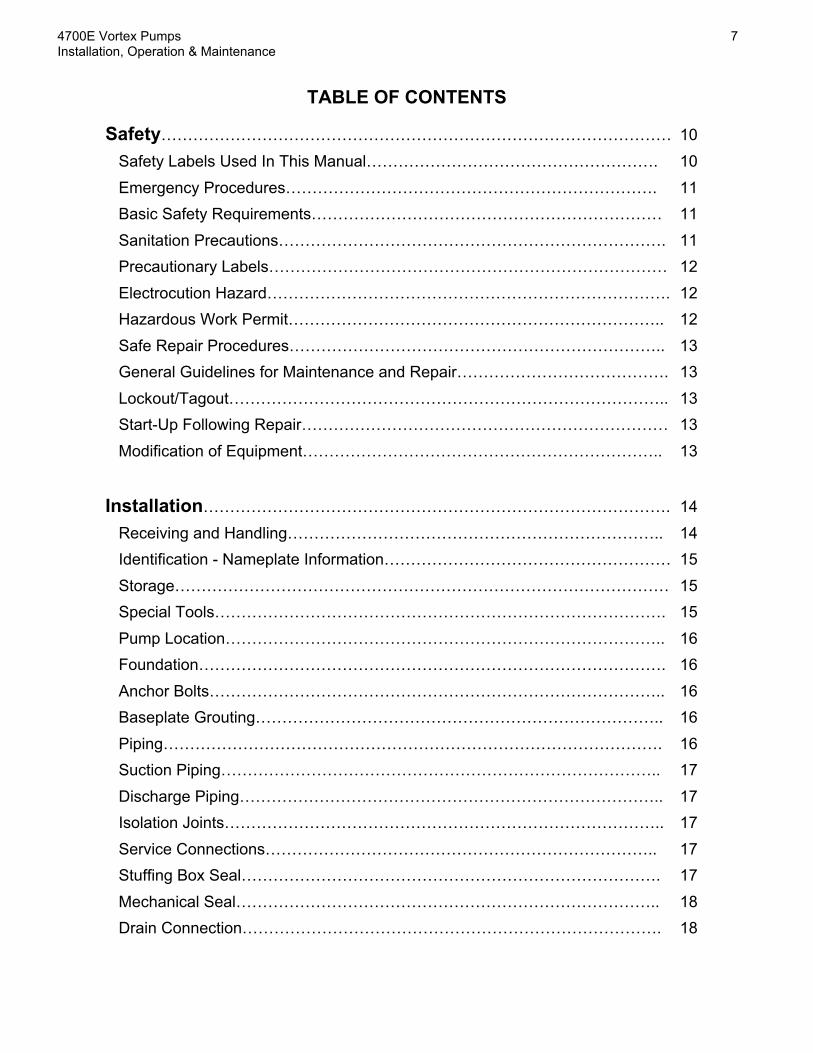
Safety…………………………………………………………………………………… 10 Safety Labels Used In This Manual………………………………………………. 10 Emergency Procedures……………………………………………………………. 11 Basic Safety Requirements………………………………………………………… 11 Sanitation Precautions………………………………………………………………. 11 Precautionary Labels………………………………………………………………… 12 Electrocution Hazard…………………………………………………………………. 12 Hazardous Work Permit…………………………………………………………….. 12 Safe Repair Procedures…………………………………………………………….. 13 General Guidelines for Maintenance and Repair…………………………………. 13 Lockout/Tagout……………………………………………………………………….. 13 Start-Up Following Repair…………………………………………………………… 13 Modification of Equipment………………………………………………………….. 13
Installation……………………………………………………………………………. 14 Receiving and Handling…………………………………………………………….. 14 Identification - Nameplate Information……………………………………………… 15 Storage………………………………………………………………………………… 15 Special Tools…………………………………………………………………………. 15 Pump Location……………………………………………………………………….. 16 Foundation……………………………………………………………………………. 16 Anchor Bolts………………………………………………………………………….. 16 Baseplate Grouting………………………………………………………………….. 16 Piping…………………………………………………………………………………. 16 Suction Piping……………………………………………………………………….. 17 Discharge Piping…………………………………………………………………….. 17 Isolation Joints……………………………………………………………………….. 17 Service Connections……………………………………………………………….. 17 Stuffing Box Seal……………………………………………………………………. 17 Mechanical Seal…………………………………………………………………….. 18 Drain Connection……………………………………………………………………. 18

8 4700E Vortex Pumps Installation, Operation & Maintenance
11/16/12 Fairbanks Nijhuis™
Field Alignment………………………………………………………………………. 18 V-Belt Arrangement…………………………………………………………………. 18 Direct Coupled Arrangement……………………………………………………….. 19 Belt or Coupling Guards…………………………………………………………….. 19
Operation……………………………………………………………………………… 20 Pre-Startup Checklist………………………………………………………………… 20 Startup Checklist……………………………………………………………………… 21 Turning the Pump On………………………………………………………………… 22 Operating the Pump………………………………………………………………….. 22 Pressure Measurement……………………………………………………………… 22 Motor Amp Draw……………………………………………………………………… 22 Power Supply Voltage……………………………………………………………….. 23 Throttling………………………………………………………………………………. 23 Pump Speed………………………………………………………………………….. 23 Turning the Pump Off…………………………………………………………………. 23
Maintenance………………………………………………………………………….. 24 General Preventative Maintenance………………………………………………… 24 Motor Maintenance and Lubrication………………………………………………… 24 Belt and Sheave Maintenance………………………………………………………. 25 Direct Coupling Maintenance………………………………………………………… 25 Pump Bearing Lubrication - Oil……………………………………………………… 25 Pump Bearing Lubrication - Grease………………………………………………… 26 Wet End Maintenance………………………………………………………………… 26
List of Figures and Tables
Figure 1: Fairbanks Morse Nameplate………………………………………………. 15Table 1: Motor Grease Quantity……………………………………………………… 25

4700E Vortex Pumps 9Installation, Operation & Maintenance
Fairbanks Nijhuis™ 11/16/12
4700E - Assembly and Disassembly…………………………………….. 27
4700E Exploded View……………………………………………………………….. 27Disassembly Procedure……………………………………………………………... 27 Rotating Assembly Removal – Back Pull Out Design……………………… 27
Impeller Removal……………………………………………………………… 28Backplate and Packing Gland Housing Removal………………………….. 28Shaft Sleeve Removal………………………………………………………… 28Shaft and Bearing Removal………………………………………………….. 29Case Removal…………………………………………………………………. 29Cleaning and Inspection……………………………………………………… 29
Assembly Procedure………………………………………………………………… 30Pre-Assembly Inspection……………………………………………………. 30Bearing Assembly…………………………………………………………….. 30Shaft Assembly……………………………………………………………….. 30Bearing Caps Assembly……………………………………………………… 31Packing Gland and Shaft Sleeve Assembly – Stuffing Box……………… 31Packing Gland and Shaft Sleeve Assembly – Mechanical Seal………… 32Impeller Installation…………………………………………………………… 32Case Installation……………………………………………………………… 33
List of Figures and Tables
Table 2: 4700E Packing Arrangement and Size…………………………..………. 32Table 3: 4700E Impeller Fastening Torque Values………………………..………. 33

10 4700E Vortex Pumps Installation, Operation & Maintenance
11/16/12 Fairbanks Nijhuis™
Safety
This chapter contains information to promote safety in the operation and maintenance of this equipment. It is notintended to supersede, replicate, or replace any safety documentation or procedures provided from or established byofficial safety sources.
All persons involved in the operation of this equipment⎯plant engineering, operations, and management⎯mustunderstand the potential hazards involved and observe the required safety precautions. Only trained and responsiblepersonnel should work with or around this equipment.
Your safety and the safety of equipment, nearby facilities, and personnel require a proper safety attitude and anemphasis on safe work procedures. This is the essence of any good safety program. If at any time you identify safetydeficiencies, immediately correct them and bring them to the attention of management. Before an accident can beprevented, it must be anticipated. Use pre-job discussions with your co-workers and supervisors to identify hazardsand the means to avoid them.
Safety Labels Used In This ManualFailure to follow the procedures in this manual can lead to injury, loss of property, or death. In most cases, particularlysensitive procedures are called out with the following symbols:
Procedures than can jeopardize the pumping unit or otherproperty are designated with this symbol.
Procedures that have a general hazard to personnel or safetyare designated with this symbol.
Procedures that pose a risk of electrocution are designated withthis symbol.
Information that is critical to the safe operation of the equipment is called out with the following symbol:
This symbol calls out important information that may not beincluded in the text.

4700E Vortex Pumps 11Installation, Operation & Maintenance
Fairbanks Nijhuis™ 11/16/12
Emergency ProceduresThe Fairbanks Morse pump is designed to operate safely, efficiently, and reliably. However, as with any operatingsystem, an emergency can occur at any time. An emergency response could involve calling for medical assistance,management notification, fire assistance, or evacuation from the vicinity of the equipment. Obtain the followingemergency phone numbers and post them at site telephone locations. Periodically review the numbers for accuracyand update them as required.
Table 1.1 Emergency Phone NumbersAmbulance (______) _______-_______________Fire Department (______) _______-_______________
Police Department (______) _______-_______________
Fairbanks MorseRepresentative
( 913) 371-5000
Training and education are the most important parts of any safety program. For every possible emergency, establishan Emergency Response Plan and maintain it for immediate use.
Basic Safety RequirementsBe aware of the following safety guidelines:
• Prevent electrical shock – Disconnect the power cord from the equipment before working on it. Usetools designed for work on electrical equipment.
• Prevent injury – Wear safety glasses and other appropriate safety protection when the MaterialSafety Data Sheet or safe working procedure dictates. Ensure that all tools and instruments usedduring installation and maintenance are in good condition.
• Protect equipment and personnel – Check all safety devices periodically to ensure continuedreliability. Provide proper maintenance of all safety valves. Never bypass safety devices, and neveroperate the equipment outside its specified limits.
• Follow posted precautions – Read all precautionary labels attached to equipment and posted inareas of the facility. Comply with all precautions before handling the equipment.
Situations may develop for which no written procedures exist. Think carefully before acting. Know the function of eachpart and its effect on the process and equipment. Carefully review all operating procedures before starting up thisequipment to ensure knowledge and understanding.
Sanitation Precautions
Follow the safety precautions established by your facility forwastewater sanitation.
Wastewater contains potentially dangerous bacteria, viruses, and pathogens. When working in or around equipmentoperating in wastewater treatment facilities, exercise all required precautions for personal sanitation.

12 4700E Vortex Pumps Installation, Operation & Maintenance
11/16/12 Fairbanks Nijhuis™
Precautionary Labels
To avoid serious injury, read all precautionary labels attachedto equipment and boxes prior to start-up.
The precautionary labels warn you of inherent hazards associated with the system. Before handling the equipment,read and understand the precautionary labels and follow the instructions they contain. Do not remove or obscure anylabel. If a label is missing or difficult to read, replace it with a new one. Labels are available from your FairbanksMorse representative.
Electrocution Hazard
Electric shock can kill. Use extreme caution if troubleshootingor servicing this equipment. Do NOT bypass safety interlocks.An electrocution hazard exists even after the equipment hasbeen de-energized. Only qualified personnel who are incompliance with all applicable federal, state, and local codesshall perform electrical wiring.
Adherence to the following guidelines will help guard against possible electrocution:
• Use only factory-approved components for repair. Tampering or unauthorized substitution ofcomponents may adversely affect the safety of this equipment.
• Turn off the power before opening the equipment, or checking or replacing any component.
• Carefully follow all Hazardous Work Permit and Lockout/Tagout procedures for your facility.
• Do not touch live electrical components inside the equipment; electric shock caused by voltage inthe control circuits can kill.
• Keep all equipment surfaces very clean. Do not allow grease or oil deposits on bypass interlocks orother safety devices.
Hazardous Work PermitThe purpose of a Hazardous Work Permit (HWP) is to ensure that work known to be hazardous, or that could cause ahazard, is planned and controlled so that it is accomplished without incident. Planning the procedures and conductinga pre-job discussion with all of the participants, including a responsible manager, are necessary to ensure a safe workprocess.
The most successful way to avoid accidents is to anticipate them. In a pre-job discussion, the participants identify allthe potential hazards and develop procedures for accomplishing the task without risk. The process is formalized andthe work is begun only after the manager has issued a written permit.
4700E Vortex Pumps 13Installation, Operation & Maintenance
Fairbanks Nijhuis™ 11/16/12
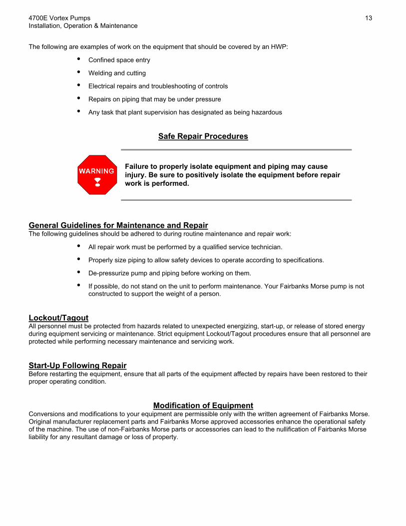
The following are examples of work on the equipment that should be covered by an HWP:
• Confined space entry
• Welding and cutting
• Electrical repairs and troubleshooting of controls
• Repairs on piping that may be under pressure
• Any task that plant supervision has designated as being hazardous
Safe Repair Procedures
Failure to properly isolate equipment and piping may causeinjury. Be sure to positively isolate the equipment before repairwork is performed.
General Guidelines for Maintenance and RepairThe following guidelines should be adhered to during routine maintenance and repair work:
• All repair work must be performed by a qualified service technician.
• Properly size piping to allow safety devices to operate according to specifications.
• De-pressurize pump and piping before working on them.
• If possible, do not stand on the unit to perform maintenance. Your Fairbanks Morse pump is notconstructed to support the weight of a person.
Lockout/TagoutAll personnel must be protected from hazards related to unexpected energizing, start-up, or release of stored energyduring equipment servicing or maintenance. Strict equipment Lockout/Tagout procedures ensure that all personnel areprotected while performing necessary maintenance and servicing work.
Start-Up Following RepairBefore restarting the equipment, ensure that all parts of the equipment affected by repairs have been restored to theirproper operating condition.
Modification of EquipmentConversions and modifications to your equipment are permissible only with the written agreement of Fairbanks Morse.Original manufacturer replacement parts and Fairbanks Morse approved accessories enhance the operational safetyof the machine. The use of non-Fairbanks Morse parts or accessories can lead to the nullification of Fairbanks Morseliability for any resultant damage or loss of property.
14 4700E Vortex Pumps Installation, Operation & Maintenance
11/16/12 Fairbanks Nijhuis™
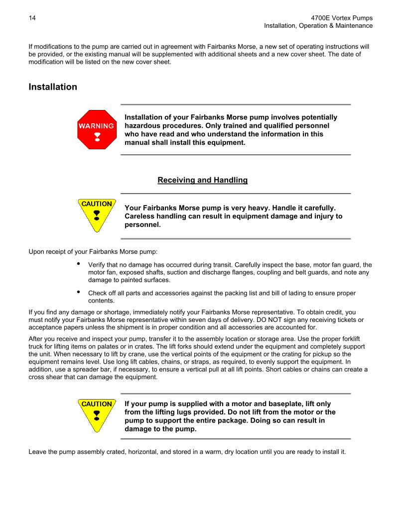
If modifications to the pump are carried out in agreement with Fairbanks Morse, a new set of operating instructions willbe provided, or the existing manual will be supplemented with additional sheets and a new cover sheet. The date ofmodification will be listed on the new cover sheet.
Installation
Installation of your Fairbanks Morse pump involves potentiallyhazardous procedures. Only trained and qualified personnelwho have read and who understand the information in thismanual shall install this equipment.
Receiving and Handling
Your Fairbanks Morse pump is very heavy. Handle it carefully.Careless handling can result in equipment damage and injury topersonnel.
Upon receipt of your Fairbanks Morse pump:
• Verify that no damage has occurred during transit. Carefully inspect the base, motor fan guard, themotor fan, exposed shafts, suction and discharge flanges, coupling and belt guards, and note anydamage to painted surfaces.
• Check off all parts and accessories against the packing list and bill of lading to ensure propercontents.
If you find any damage or shortage, immediately notify your Fairbanks Morse representative. To obtain credit, youmust notify your Fairbanks Morse representative within seven days of delivery. DO NOT sign any receiving tickets oracceptance papers unless the shipment is in proper condition and all accessories are accounted for.
After you receive and inspect your pump, transfer it to the assembly location or storage area. Use the proper forklifttruck for lifting items on palates or in crates. The lift forks should extend under the equipment and completely supportthe unit. When necessary to lift by crane, use the vertical points of the equipment or the crating for pickup so theequipment remains level. Use long lift cables, chains, or straps, as required, to evenly support the equipment. Inaddition, use a spreader bar, if necessary, to ensure a vertical pull at all lift points. Short cables or chains can create across shear that can damage the equipment.
If your pump is supplied with a motor and baseplate, lift onlyfrom the lifting lugs provided. Do not lift from the motor or thepump to support the entire package. Doing so can result indamage to the pump.
Leave the pump assembly crated, horizontal, and stored in a warm, dry location until you are ready to install it.

4700E Vortex Pumps 15Installation, Operation & Maintenance
Fairbanks Nijhuis™ 11/16/12
Identification - Nameplate InformationEach Fairbanks Morse unit is supplied with a corrosion resistant nameplate affixed to the pump.
Serial No. Capacity
P.O. No. Head
Model No. RPM
Tag No. Material
Figure 1: Fairbanks Morse Nameplate
You will need the information on the nameplate when inquiring about parts and service. Since the nameplate can bedamaged in the field, Fairbanks Morse suggests copying this information in this manual for future reference.
StorageIf you do not install the pump soon after receipt, use the following storage procedures to ensure the unit remains ingood working condition. Fairbanks Morse DOES NOT prepare the pump package for long term storage.
• Remove the packing glands, packing, and lantern ring from the stuffing box. If the pump has amechanical seal, coat the seal faces with a light lubricating oil.
• Cover all suction and discharge flanges with wood, plastic, or tape to prevent foreign material orwater from accumulating in the pump.
• Remove all casing and drain plugs to prevent accumulation of water.
• If the pump is supplied with belts and sheaves, loosen the tension on the belts.
• If the pump is supplied with oil lubricated bearings, fill the bearing housing to the top with a 20weight non-detergent oil and replace the vent. On pumps with grease lubricated bearings, re-grease before storing.
• After inspecting the pump, re-crate the unit and store it in a clean, dry place that is free fromextremes in temperature.
• Rotate the pump shaft at least 10 turns every week to prevent pitting and corrosion on the bearingsurfaces.
Special ToolsNo special tools are required for the installation of your unit.
Made in the United States of America
913/371-5000www.fmpump.com

16 4700E Vortex Pumps Installation, Operation & Maintenance
11/16/12 Fairbanks Nijhuis™
Pump LocationThe pump should be located on a flat, hard surface. The surrounding area should be open to permit easy access formaintenance and service. The pump area should have adequate headroom, sufficient ventilation, and a dry workingarea.
Before installing your pump, compare the physical location with the dimensions on the outline installation drawing toensure proper fit. You must determine that the available space is sufficient for the pump, taking into account thefollowing provisions:
• Dimension and weight of the pump package.
• Required moving and hoisting equipment.
• Possible piping layout, including space for removal and maintenance.
• Freedom of movement to operate the unit, read speed and pressure gauges, and provideadjustment and maintenance.
• Space required for lubrication.
• Space for removal of coupling and belt guards.
FoundationThe concrete pump foundation should be 4 inches wider and longer than the pump base. When installing the pump,make sure that the surface of the foundation is rough but free of debris. The foundation should be level and ofsufficient depth and strength to adequately support the pump base.
Anchor BoltsAnchor bolts should be set into the concrete foundation. For best results, use anchor bolts made of corrosion resistantmaterial such as stainless steel. Anchor bolt nuts should be of a different grade stainless steel to prevent galling.
Initially tighten the anchor bolts one eighth of a turn with a wrench. Do not fully tighten until after the pump shafts havebeen aligned and the pump base has been grouted to the foundation.
Make sure the foundation is clean, free of loose debris, andlevel. Allow grout to cure for at least two days before fullytightening the anchor bolts.
Baseplate GroutingAfter the pump has been set in place and leveled, grout the pump through the hole in the base, making sure that novoids or open spaces remain.
Piping
All piping to and from the pump must be independentlysupported. Undue stress on the pump suction or dischargeflanges can cause serious injury or equipment failure. The pipesupports should be located as close to the pump as possible.

4700E Vortex Pumps 17Installation, Operation & Maintenance
Fairbanks Nijhuis™ 11/16/12
Suction PipingThe pump should be located as near to the liquid source as possible. The suction piping should be at least the samediameter as the suction flange and should have a straight run of pipe that is a minimum of 8 to 10 pipe diameters long.If the piping must make a change in direction, use long radius fittings. Suction piping must be airtight and suitable forboth pressure and vacuum.
If the pipe diameter is increased or decreased, use eccentric pipe reducers to eliminate any space in the top of the linewhere air can accumulate. If possible, run the suction line so that the pump suction flange is the highest point in theline.
An inlet valve should be located near the pump to isolate the unit for service and repair. Never install a check valve onthe suction side of the pump. It is recommended that a compound vacuum / pressure gauge be installed to monitorpump performance.
Discharge PipingThe pump discharge piping should be a similar diameter as the discharge flange. Avoid sudden changes in pipediameter by using concentric taper increasers. Provide as straight of a pipe run as possible after the discharge of thepump. If piping must make a change in direction, use long radius fittings.
A check valve can be installed on the discharge side of the pump, and an isolation valve is required to service thepump. It is recommended that a pressure gauge be installed to monitor pump performance.
Isolation JointsElastomeric isolation joints that insulate the pump from vibration and stresses should be installed on both the suctionand discharge flanges.
All pipe flanges should be cleaned prior to the installation ofisolation joints and pipes. A clean flange will ensure a properseal. All piping, joints, and valves must be airtight.
Service ConnectionsStuffing Box SealFairbanks Morse uses graphite impregnated Teflon braided packing in stuffing box seals unless otherwise specified.This material requires a liquid flush in order to provide cooling and lubrication to the packing. The packing glandhousing has two ports to which the flushing fluid can be connected. The second port that is not used can remainplugged or can be piped to a drain. The flushing fluid should be clean and have a lubricating quality.
Seal flushing fluid should be at a pressure that is 10-15 PSIGabove the maximum discharge pressure of the pump. This willensure positive flow through the packing gland. The sealflushing fluid flow rate should be set at 0.5 to 1.5 GPMdepending on the application and severity of abrasives in thepumped fluid.
An automatic flushing system may be used to ensure that the seal flushing fluid is flowing when the pump starts. Thesystem can consist of a solenoid valve, isolation and bypass valves, an inline visual flow indicator, a throttle valve, aregulator, and a pressure gauge.

18 4700E Vortex Pumps Installation, Operation & Maintenance
11/16/12 Fairbanks Nijhuis™
Mechanical SealIf your unit has a mechanical seal, refer to the detailed manufacturer’s installation and operating literature. In general,the pump will have either a single or double mechanical seal. In most cases, seal flushing fluid is recommended. Theseal typically has a flushing port located on the seal gland plate that delivers the fluid to the seal faces. Remove theplug and pipe the flushing fluid to this connection. The seal fluid should be 10-15 PSIG above the maximum dischargepressure of the pump, and the seal fluid flow rate should be 0.5 to 1.5 GPM.
Since the cast iron gland housing for a mechanical seal and a stuffing box are interchangeable, the housing will stillhave the two flushing fluid connections as described herein. These should remain plugged.
Drain ConnectionFairbanks Morse pumps are equipped with a drain connection on either the bearing housing or the backplate thatdrains a reservoir designed to collect leakage from the packing gland housing. The drain connection should be pipedto the nearest floor drain.
Field AlignmentFairbanks Morse pump packages are initially aligned at the factory. However, due to stress encountered duringshipment, the pump alignment must be re-checked in the field prior to startup.
Failure to properly align the coupling or belts and sheaves maycause damage to the pump, property, or personnel.
V-Belt ArrangementLoosely assemble the sheaves on the pump and motor shaft. The mating surfaces of the bushing outside diameter andsheave hub inside diameter must be clean and free of all lubricants. Do not tighten the sheaves.
Use no lubricant to install the sheaves on the pump or motorshaft.
Make sure that the shafts are parallel by measuring the distance between them at three or more places. If the shaftsare not parallel, adjust as necessary.
Position both sheaves on their shafts as close to the motor or shaft bearing as possible to minimize bearing loads, butallow room for some adjustment. If a variable speed sheave is supplied, adjust its pitch diameter as required. Checkthe alignment by placing a straight edge or a piece of string across the driver sheave and the driven sheave near theircenters. The straight edge should touch each sheave on both sides so that it makes four points of contact. Tighten themotor and pump sheave to eliminate any angular movement. Recheck alignment and adjust the motor sheave asnecessary. Rotate the sheaves one half of one turn and recheck. If the sheaves are out of alignment after rotating, thepump or motor shaft may be bent.
Install the belts in the grooves on the sheaves. Tension the belts in accordance with the instructions provided herein.

4700E Vortex Pumps 19Installation, Operation & Maintenance
Fairbanks Nijhuis™ 11/16/12
Improperly adjusted sheaves and belts may cause prematurebelt wear and excessive vibration. This can damage the pumpshaft, bearings, or seals.
Refer to all sheave and belt manufacturer’s installation andoperation instructions if provided with your unit. Themanufacturer’s instructions supercede all Fairbanks Morseinstructions unless specifically noted.
Direct Coupled ArrangementThe pump and driver shafts must be checked for parallel and angular alignment. Parallel alignment should be checkedwith a straightedge, and angular alignment should be checked with a micrometer, calipers, taper gauge, or a laseralignment tool. Refer to the coupling manufacturer’s installation and operation instructions for acceptable maximumallowable misalignment.
Belt or Coupling GuardsReplace the belt or coupling guards after all alignment and adjustment.
Failure to replace the guards when operating can result in injuryand damage to the equipment.
California Proposition 65 Warning
This product and related accessories contain chemicals knownto the state of California to cause cancer, birth defects or otherreproductive harm.

20 4700E Vortex Pumps Installation, Operation & Maintenance
11/16/12 Fairbanks Nijhuis™
Operation
Operation of your Fairbanks Morse pump involves potentiallyhazardous procedures. Only trained and qualified personnelwho have read and who understand the instructions in thismanual, the reference publications, and the supplier manualsshall operate this equipment.
The following procedures should be used for the safe operation of your pump.
Pre-Startup ChecklistAll of the following items should be verified prior to startup.
• ALIGNMENT: Recheck the alignment as outlined herein.
• FREE ROTATION: Turn the pump shaft by hand. The shaft should rotate freely.
• DEBRIS: All construction debris should be removed from the suction piping and suction well.
• GUARDS: Make sure that all coupling or belt guards are in place.
• MOTOR: Prepare the motor as outlined in the motor manufacturer’s installation and operationmanual. A motor starter with overload protection should be provided, and proper wire size, fusesize, and other electrical devices should conform to local code and regulation.
• LUBRICATION: Oil lubricated pumps may be shipped with or without oil. It is necessary to checkthe level of the oil through the sight glass or constant level oiler to determine if there is oil in thepump. Before starting the pump, fill the bearing housing with a SAE 20 non detergent oilcontaining rust inhibitors (Mobil DTE 25 or equal). Operate the pump (ONLY AFTERFOLLOWING ALL OF THE PROCEDURES IN THIS SECTION) for two minutes then drain the oilfrom the housing and refill with fresh oil. Do not operate the pump without lubrication as this willresult in bearing failure. Grease lubricated pump bearings are packed at the factory with an NLGInumber 2 grease such as Shell Dolium R. The pump bearings should be topped off with 4-5squeezes from a low pressure grease gun prior to initial operation.
• SEAL FLUSH – STUFFING BOX: Before starting your pump, it is necessary to provide sealflushing fluid to the stuffing box four to six hours prior to operation. This will ensure that thepacking is fully swelled with lubricating fluid. Initially allow a generous amount of fluid to leak fromthe back of the packing gland housing – there should be a steady stream. This can beaccomplished by loosening the split gland turning the seal fluid on. When you start the pump,adjust the flushing fluid so there is 1-2 drops per second. After the pump runs for four to six hours,adjust the packing gland so that drip rate is approximately 60 drops per minute.
• SEAL FLUSH – MECHANICAL SEAL: The mechanical seal requires seal flushing fluid to preventscoring of the seal faces. Turn on the seal flushing fluid five minutes prior to starting the pump.
• ROTATION: Jog the motor to check for rotation. A rotation arrow is cast on the pump case and isalso indicated on the pump data sheet. Adjust the motor leads as necessary.

4700E Vortex Pumps 21Installation, Operation & Maintenance
Fairbanks Nijhuis™ 11/16/12
Startup Checklist
PROCEDURE YES NO NA COMMENTS / CONDITIONSIDENTIFICATION
1. Date of initial operation:2. Pump model and serial number (from nameplate):3. Installation site and tag number:4. Purchase order number:
____________________________________________________________________________________________________________________________________________________________________________________________________
RECEIVING1. Is there any visible damage?2. Have all items been received?
STORAGE1. Was equipment stored in a dry area?2. Have storage instructions been followed?
INSTALLATION1. Is paint in good condition?2. Is piping independently supported?3. Are all piping joints leak tight?4. Is the foundation level?5. Is the base bolted down?6. Is the base grouted in position?7. Are all bolts and fasteners tight?8. Are all service connections properly connected?9. Are accessories mounted and operating properly?10. Are all guards in place?
LUBRICATION1. Has the proper grade and amount of oil been added?2. Is the oil breather installed properly?3. Have the motor bearings been greased?4. Have the pump bearings been greased (if equipped)?5. Has the coupling been lubricated (if required)?
ALIGNMENT1. Has the belt tension been checked?2. Have the sheaves been aligned?3. Has the direct coupling been checked (if required)?4. Have the shafts been checked with an indicator (direct
coupled)?ROTATION
1. Does the shaft turn freely by hand?2. Has the seal flushing fluid been turned on?3. Are the flushing fluid flow and pressure adequate?4. Is the shaft rotation correct?
OPERATION1. Does the pump operate smoothly?
ELECTRICAL DATAMotor Manufacturer: Operating Amperage Operating VoltageNameplate Horsepower: L1-L2: L1-L2:RPM: L2-L3: L2-L3:Nameplate Voltage / FLA: / L1-L3: L1-L3:
SYSTEM DATA Point 1 Point 2 Point 3Pumped Fluid: Suction Pressure:Temperature: Discharge Pressure:Specific Gravity: Pump Speed:Percent Solids: Flow Rate:
SIGNATURESRepresentative Name: Contractor Name and Date:Company: Contractor Signature:Phone: Owner’s Name and Date:
Owner’s Signature:

22 4700E Vortex Pumps Installation, Operation & Maintenance
11/16/12 Fairbanks Nijhuis™
Turning the Pump On
The risk of exposure to electrical hazards must be eliminated.Be sure that the wiring, connections, and other electricaldevices are operating properly.
All guards and safety devices must be installed prior tooperating the pump.
Once all of the items in the Pre-Startup Checklist have been verified, follow the following procedure to start the pump.
• Turn on the seal flush system.
• Fully open the suction valve and flood the pump with liquid. A positive suction head is desired. Ifthe pump must pull from suction, prime the pump.
• Engage the motor.
• Immediately open the discharge valve.
• If there are any loud or unusual noises, immediately turn the pump off.
Operating the PumpThe following section provides details on the safe operation of your pump.
Pressure MeasurementThe suction and discharge pressure should be measured to verify that the pump is operating at its design point asspecified on the pump nameplate or in the pump data sheet.
Failure to operate at the design point can cause excessivevibration, increased motor amperage draw, and increased wearof the wetted parts.
Motor Amp DrawThe current required by the pump motor will vary for different applications. In general, the pump is designed to operatefrom 50% to 95% of the full load amps stamped on the motor nameplate. Using an accurately calibrated amprobe,check all three phases of the motor and record.
Immediately report abnormal amperage to site management. If the pump motor is pulling normal current, recheck it 30minutes after you start it. This allows the motor sufficient warm-up time. The reading you obtain should be the readingof the unit’s normal operating range. DO NOT operate the pump motor above the full load amperage stamped on themotor nameplate.

4700E Vortex Pumps 23Installation, Operation & Maintenance
Fairbanks Nijhuis™ 11/16/12
Power Supply VoltageStandard voltage offered by motor manufacturers is typically 230/460 volt. Since it is unlikely that your voltage isexactly standard, motor manufacturers allow a +10 percent variation in the operation of their motors. This variation canbe tolerated on all voltage variations at the rated frequency. Both the motor manufacturer and Fairbanks Morse arenot responsible for motor failure due to the use of incorrect voltage. Also, neither is responsible for motor failuredue to unbalanced voltage of the three phases. If you have a high, low, or unbalanced voltage problem, correct itbefore connecting any motors to it.
Throttling
Never throttle the pump on its suction side. This will causedamage. Do not operate the pump against a closed dischargevalve.
The discharge valve may be throttled to provide variable capacity. The suction side of the pump should remain openand free of obstruction.
Pump SpeedThe pump speed should be measured after the first four to six hours of operation to ensure that the speed is setcorrectly and has not changed.
Turning the Pump OffThe following procedure should be followed to stop the pump.
• Close the discharge valve to prevent backflow.
• Immediately de-energize the motor.
• Isolate any seal flushing fluid connections.
• Close the suction valve.
• If the pump is out of service for more than two weeks, refer to the storage instructions herein.

24 4700E Vortex Pumps Installation, Operation & Maintenance
11/16/12 Fairbanks Nijhuis™
Maintenance
Maintenance and repair of your Fairbanks Morse unit involvespotentially hazardous procedures. Only trained and qualifiedpersonnel who have read and who understand the informationpresented in this manual, the reference publications, and thesupplier manuals shall maintain and repair this equipment.
Your Fairbanks Morse pump is designed to operate efficiently with very little maintenance. However, as with anyequipment, malfunctions can occur. To keep your unit running well, preventive maintenance is essential.
General Preventative MaintenanceCheck the following items in the intervals listed below:
• Check gauges on pump suction and discharge and pump operating speed to confirm operatingpoint (every 3 months).
• Check bearing temperature and compare with earlier readings (every 3 months).
• Listen for metal to metal scraping sound or other odd noises (every 3 months).
• Adjust packing or mechanical seal as necessary (every 3 months).
• Run an amperage reading to verify that the motors are running normally (every 6 months).
• Inspect the fan guard and remove any accumulated debris from under it and around the motor(every 6 months).
• Tighten any fasteners that may be loose (every 6 months).
• Check shaft sleeve under packing for wear (every 6 months).
• Check shaft for runout and straightness (every 6 months).
• Check the pump alignment and adjust the belts or coupling as necessary (every 6 months).
• Inspect the impeller, case, suction flange, and wearplate for wear (every 12 months).
• Lubricate the motor as listed herein.
• Lubricate the pump as listed herein.
Motor Maintenance and LubricationLubricate the motor every six months. Most motors have a grease fitting for grease-through lubrication. This fitting isfound on the outer frame of the motor at both the top and bottom motor bearings. Just opposite (90 degrees) from thefitting is the relief plug. This may be a spring-loaded, pressure-relief plug that does not need to be removed beforelubrication.
Use the following grease to lubricate the motor:
• Shell Dolium R (recommended)
• Standard of California Chevron SRI-2

4700E Vortex Pumps 25Installation, Operation & Maintenance
Fairbanks Nijhuis™ 11/16/12
When lubricating, clean the tip of the fitting and snap the grease gun onto the zerk fitting. Apply grease as follows:
Motor Frame Size Pumps from Gun
Through 254 1-2
254-365 2-3
365 plus 3-4
Table 1: Motor Grease Quantity
Never over-grease the bearings. After applying the recommended amount of grease, remove the gun and clean it.
Belt and Sheave MaintenanceCheck the alignment of the belts and sheaves as outlined herein. To install the belts, shorten the center distancebetween the driven and driver sheaves. Lay the belts into the sheave grooves without the use of force. While the beltsare still loose on the drive, rotate the drive by hand until the slack is evenly distributed on both sides. Increase thecenter distance until the belts are snug. The drive can then be tensioned.
Never roll or pry the belts into the sheave grooves. This candamage the belt cords and lead to belt turnover, short life, oractual breakage. It is unsafe to install belts this way.
Keep take-up rails, motor bases, and other means of centerdistance adjustment free of dirt, rust, and grit. Lubricateadjusting screws and slide rails from time to time.
Operate the drive for five minutes to seat the belts in the sheave grooves. Observe the operation of the drive under itshighest load condition, usually on startup. A slight bowing of the slack side of the drive indicates proper tension. If theslack side remains taut during the peak load, the drive is too tight. Excessive bowing or slippage indicates insufficienttension. If the belts squeal as the motor starts or at some subsequent peak load, they are too loose and can not deliverthe required torque. The drive should be stopped and the belts should be tightened.
Check the tension on a new drive frequently during the first day of operation by observing the slack side span. Afterseveral days of operation the belts will seat themselves in the sheave grooves. It may be necessary to readjust thedrive at this time.
Direct Coupling MaintenanceThe direct coupling should be aligned as indicated herein. Inspect the coupling periodically for signs of wear.
Pump Bearing Lubrication - OilOil lubricated pumps require a SAE 20 non detergent oil containing rust inhibitors (Mobil DTE 25 or equal). Theoil should be changed every four to six months, depending on duty cycle and ambient conditions.

26 4700E Vortex Pumps Installation, Operation & Maintenance
11/16/12 Fairbanks Nijhuis™
When changing oil in the pump bearings, refill to the center line of the site glass when the pump is at rest.Approximate volume is: Model E – .60 quarts
A contact type or immersion thermometer mounted on the bearing housing can be used to measure the bearingtemperature. Do not test by hand, as the pump case may be hot. Normal bearing temperatures can be anywhere from90°F to 170°F, depending on ambient conditions. Oil lubricated bearings can be safely operated up to 200°F. Achange in temperature may indicate damage that requires attention.
Pump Bearing Lubrication - GreaseGrease lubricated pump bearings require an NLGI Number 2 grease such as Shell Dolium R or equal. The bearingsshould be greased every four to six months, depending on duty cycle and ambient conditions. Use a low pressuregrease gun to pump grease into the zerk fitting until grease can be seen exiting from grease relief. If your pump wasshipped without grease fittings, remove the plugs and replace them with a zerk fitting and spring loaded grease relief.
When rebuilding the pump or replacing the bearings, pack the bearings with grease prior to installing the shaft in thebearing housing.
Wet End MaintenanceThe wet end of the pump, which generally consists of the impeller, wearplate, suction flange, and case, does notrequire any maintenance. These parts should be inspected periodically to prevent unforeseen problems.
If you find that your parts are wearing excessively, Fairbanks Morse offers a wide variety of materials with enhancedabrasion resistance. Our premier Super XT Ni-Hard provides maximum abrasion resistance.

4700E Vortex Pumps 27Installation, Operation & Maintenance
Fairbanks Nijhuis™ 11/16/12
4700E – Assembly and Disassembly
Close all valves before and after the pump to isolate the unit. Ifapplicable, isolate seal water. Lock out the unit to ensure thatthe pump does not start while working on it. Turn off all powerto the pump motor. Drain the oil from the pump if so equipped.
4700E Exploded ViewThe exploded view contains part reference numbers that are used in the assembly and disassembly procedure.
Disassembly ProcedureThe following procedure should be used to disassemble the pump.
Rotating Assembly Removal – Back Pull Out DesignThe case may be left in place if service is to be performed on the shaft, sleeve, impeller, bearing frame, or shaft seal.
• Support the case independent of the piping so that no force is transferred from the piping to thecase. Undue stress on the suction or discharge flanges may cause the case to crack. The casemay be supported by blocking underneath with wood or by slinging with an overhead hoist.
• Remove the coupling or belt guard. Remove the motor coupling or belt pulley from the pump shaft.

28 4700E Vortex Pumps Installation, Operation & Maintenance
11/16/12 Fairbanks Nijhuis™
• Unbolt the pump from its base.
• Remove the case bolts from the back of the case to free the bearing frame (No. 5). The pump cannow be lifted from the base.
Impeller Removal• Remove the set screw from the impeller bolt (No. 8). The set screw may be difficult to remove
since it is installed with thread locker. You may need to apply heat to break the bond.
The impeller will be free once the impeller bolt is removed. Takethe necessary precautions to prevent the impeller from falling.
• Loosen and remove the impeller bolt (No. 8). Again, heat may be required as the bolt is installedwith red permanent thread locker.
• The impeller (No. 3) should slide off of the shaft. Remove the impeller key (No. 10).
• Remove and discard the case gasket (No. 11).
Backplate and Packing Gland Housing Removal
The backplate and packing gland are a single piece casting.
• For PACKING ARRANGEMENT: Loosen and remove the split gland (No. 14) from the packinggland housing (No. 4). For MECHANICAL SEAL ARRANGEMENT: Loosen and remove the sealper the manufacturer’s recommendation.
• Remove the lantern ring and packing from packing gland housing if so equipped. These parts mayalso be removed with the backplate and packing gland as well.
• Slide the backplate and packing gland forward off of the bearing frame (No. 5).
Shaft Sleeve Removal• Slide the shaft sleeve towards the impeller end of the shaft and remove.
• Remove the shaft sleeve gasket slinger (No. 18) from the shaft (No. 7).
4700E Vortex Pumps 29Installation, Operation & Maintenance
Fairbanks Nijhuis™ 11/16/12
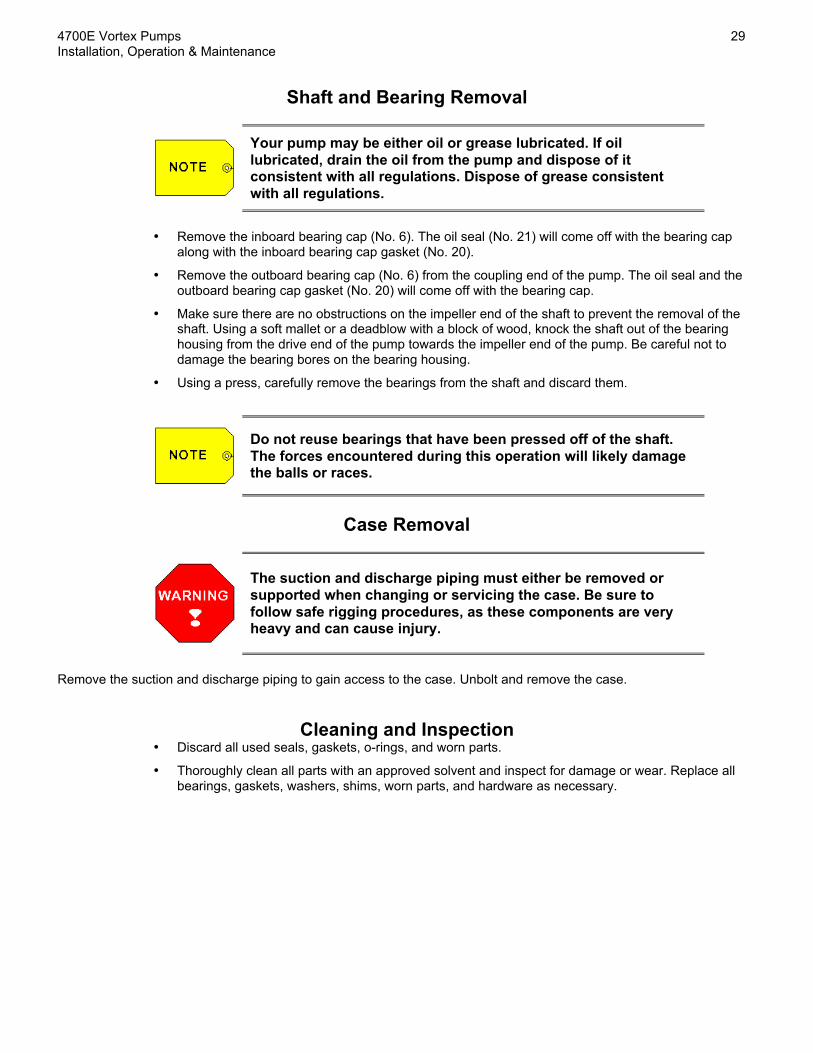
Shaft and Bearing Removal
Your pump may be either oil or grease lubricated. If oillubricated, drain the oil from the pump and dispose of itconsistent with all regulations. Dispose of grease consistentwith all regulations.
• Remove the inboard bearing cap (No. 6). The oil seal (No. 21) will come off with the bearing capalong with the inboard bearing cap gasket (No. 20).
• Remove the outboard bearing cap (No. 6) from the coupling end of the pump. The oil seal and theoutboard bearing cap gasket (No. 20) will come off with the bearing cap.
• Make sure there are no obstructions on the impeller end of the shaft to prevent the removal of theshaft. Using a soft mallet or a deadblow with a block of wood, knock the shaft out of the bearinghousing from the drive end of the pump towards the impeller end of the pump. Be careful not todamage the bearing bores on the bearing housing.
• Using a press, carefully remove the bearings from the shaft and discard them.
Do not reuse bearings that have been pressed off of the shaft.The forces encountered during this operation will likely damagethe balls or races.
Case Removal
The suction and discharge piping must either be removed orsupported when changing or servicing the case. Be sure tofollow safe rigging procedures, as these components are veryheavy and can cause injury.
Remove the suction and discharge piping to gain access to the case. Unbolt and remove the case.
Cleaning and Inspection• Discard all used seals, gaskets, o-rings, and worn parts.
• Thoroughly clean all parts with an approved solvent and inspect for damage or wear. Replace allbearings, gaskets, washers, shims, worn parts, and hardware as necessary.

30 4700E Vortex Pumps Installation, Operation & Maintenance
11/16/12 Fairbanks Nijhuis™
Assembly ProcedureThe following procedure should be used to assemble the pump.
Pre-Assembly Inspection• Inspect all existing parts and replacement parts and make sure all are clean and undamaged.
Parts that should be replaced as part of a complete pump rebuild include bearings, oil seals,bearing cap shims, all gaskets, o-rings, and any other item that is worn or damaged.
• Inspect the bearing bores on the bearing housing to make sure they are within tolerance. Boresshould be round and without grooves or other signs of wear.
• Make sure the bearing housing is free of dirt, filings, or other debris. An unclean bearing housingwill greatly reduce the life of the bearings.
Bearing Assembly• Heat the bearings in an oil bath or with an induction heater to 185°F.
• Inspect the shaft and bearing races for burrs and remove as required. Coat the shaft with a lightlubricating oil and slide on the hot inboard bearings followed by the outboard bearings. Thebearings should slip easily on the shaft. Do not press the bearings on the shaft.
The inboard bearing arrangement is critical. The external snapring must be positioned so that it is closest to the impeller endof the shaft. The outboard arrangement is not critical. However,if you pump is grease lubricated, the grease shields must bepositioned inward away from the bearing caps.
• All bearings should be seated against the shoulder of the shaft.
• Inspect the bearings and make sure that all rotate freely.
Shaft Assembly• Coat the outer races of the bearings and the inner diameter of the bearing housing bores with a
light lubricating oil. Make sure there is no dirt or debris on either the bearings or the bearinghousing bores.
• Slide the shaft into the pump from the front making sure that the inboard bearings engage thebearing housing bore flush and straight. Tap the impeller end of the shaft with a soft hammer ordeadblow with a piece of wood and slide the shaft and bearing assembly into the bearing housing.
Do not force the shaft and bearings into the bearing housing!This may cause damage to the bearings.

4700E Vortex Pumps 31Installation, Operation & Maintenance
Fairbanks Nijhuis™ 11/16/12
• You may find it easier to install the shaft and bearings when the bearing frame is set on end andthe shaft is dropped vertically into the bearing frame. You will have to block the bottom of thebearing frame up off of your working surface to allow the shaft to drop through the end of thehousing.
• Tap the shaft and bearings into the housing until it sets against firmly against the shoulder of thehousing.
The following alternate installation method may be used forbearing and housing fits that are tight.
• Set the shaft with bearings into the bearing frame that has been stood on end. Take at least twosuitable pieces of all-thread with nuts and thread into the bearing cap holes on the bearing frameat 180° apart. Place the bearing cap over the bearing and evenly tighten the nuts on the all-thread,drawing the bearings into the housing. This will prevent any shock or impact to the balls and racesof the bearings. Tighten the all-thread until the bearings are firmly seated into the housing.Remove the all-thread and replace with the bearing cap nuts and washers.
Bearing Caps Assembly• Press a new oil seal (No. 21) into the inboard and outboard bearing caps (No. 6).
• Replace the bearing cap o-ring (No. 20) on S frame bearing caps if so equipped.
• Coat the inboard oil seal surface and the shaft with a light lubricating oil. If the oil seal is equippedwith a tensioning spring, make sure that the spring stays in place during assembly.
• Replace the Teflon inboard bearing cap gasket (No. 23) on M frame bearing caps if so equipped.
• Tighten the inboard bearing cap into place.
• Coat the outboard oil seal surface and the shaft with a light lubricating oil. If the oil seal isequipped with a tensioning spring, make sure that the spring stays in place during assembly.
• Replace the plastic outboard bearing cap gasket (No. 23) on M frame bearing caps if so equipped.
• Tighten the outboard bearing cap into place. No additional adjustment is required.
• Make sure that the shaft rotates smoothly.
Packing Gland and Shaft Sleeve Assembly – Stuffing Box• On pumps equipped with a stuffing box seal, set the packing gland housing (No. 4) on a flat
surface and place the shaft sleeve (No. 17) in the center of the stuffing box bore. Make sure thatthe sleeve is facing the correct position.
• Leave the shaft sleeve in place and insert the first ring of the packing set (No. 13) until it sits flushon the shoulder on the bottom of the packing gland. Follow the packing order as shown in thefollowing table. Insert the split Teflon lantern ring (No. 12) as indicated on the chart. Stagger theends on both the packing rings and the lantern ring.

32 4700E Vortex Pumps Installation, Operation & Maintenance
11/16/12 Fairbanks Nijhuis™
Pump Size Packing Order Packing Size
S Frame Pumps 2 rings – lantern – 3rings
3/8” square – 5-1/8” long
M Frame Pumps 2 rings – lantern – 3rings
3/8” square – 6-5/8” long
Table 2: 4700E Packing Arrangement and Size
• Place the slinger (No. 18) on the shaft.
• Once the packing and the lantern ring are installed in the packing gland housing, ensure that theshaft is free of debris and burrs. Coat the shaft with a never-seize compound.
• Line up the key slot on the shaft sleeve with the impeller drive key groove on the end of the shaftand slide the entire packing gland housing with shaft sleeve onto the shaft. Bolt the gland housingand backplate in place.
• Install the split gland (No. 14) with the stainless steel studs, washers, and nuts.
• Adjust new packing as outlined herein.
Packing Gland and Shaft Sleeve Assembly – Mechanical Seal
The order of this procedure may be different depending uponthe type of mechanical seal in your pump. Study the sealmanufacturer’s installation manual before proceeding.
• On pumps equipped with a mechanical seal, place the slinger (No. 21) on the shaft.
• Ensure that the shaft is free of debris and burrs. Coat the shaft with a never-seize compound.
• Line up the key slot on the shaft sleeve with the impeller drive key groove on the end of the shaftand slide the entire packing gland housing with shaft sleeve onto the shaft. Bolt the gland housingand backplate in place.
• Install the mechanical seal per the manufacturer’s recommendations.
Impeller Installation• Inspect the shaft and make sure that it is free of nicks or burrs. Inspect the impeller bore for signs
of wear.
• Fairbanks Morse supplies impellers that are balanced. This is critical to trouble free operation.
• Replace the impeller key (No. 10), align the impeller on the shaft, and slide the impeller in place.
• Clean and degrease the impeller bolt (No. 8) and coat with permanent thread locker. Tighten theimpeller bolt onto the shaft at the values listed below:

4700E Vortex Pumps 33Installation, Operation & Maintenance
Fairbanks Nijhuis™ 11/16/12
Pump Size Torque (ft-lbs)
S Frame 50
M Frame 150
Table 3: 4700E Impeller Fastening Torque Values
• Coat the impeller bolt set screw with permanent thread locker and install in the hole provided on theimpeller bolt.
Case Installation• Remove all old gaskets and clean the surface of the case and the backplate. Install a new case
gasket (No. 11).
• Install the bolts, making sure that the case is centered. It may be necessary to hold the case inplace with an overhead hoist.
• Tighten the case bolts with a torque wrench to 25 ft-lbs in a star pattern. When you get back to thefirst bolt, increase the torque to 40 ft-lbs and repeat.
• Reconnect piping and service connections. Lubricate the pump as listed herein.

THIS PAGE INTENTIONALLY LEFT BLANK

THIS PAGE INTENTIONALLY LEFT BLANK

MODEL 4700EVORTEX PUMPS (RECESSED IMPELLER)INSTALLATION, OPERATION AND MAINTENANCE MANUAL
3601 FAIRBANKS AVENUEKANSAS CITY, KS 66106PHONE: 913.371.5000FAX: 913.748.4025WWW.FAIRBANKSNIJHUIS.COM