400mr hardware maint apr9 2010
Post on 22-Oct-2015
265 views
TRANSCRIPT
400-MR Console Hardware Maintenance Training
Course
TAC_HW_400MR_01
Rev 3
09Apr2010


400-MR Console Hardware Maintenance Training
Course
TAC_HW_400MR_01
Rev 3
09Apr2010
Publication Title
Applies to 400-MR
Publication Number, Revision Level
Revision history:
Applicability:
Varian NMR spectrometer systems with workstations running VnmrJ 3.0 software
Technical contributions: Alberto Ramirez & Andy Myles
Technical writer and editor: Ken Kezeor, Alberto Ramirez & Andy Myles
Copyright ” 2010 by Varian, Inc., NMR Systems
2700 Mitchell Drive Walnut Creek CA 94598
1-800-356-4437
www.varianinc.com
All rights reserved. Printed in the United States.
The information in this document has been carefully checked and is believed to be entirely reliable. However,
no responsibility is assumed for inaccuracies. Statements in this document are not intended to create any
warranty, expressed or implied. Specifications and performance characteristics of the software described in
this manual may be changed at any time without notice. Varian reserves the right to make changes in any
products herein to improve reliability, function, or design. Varian does not assume any liability arising out of
the application or use of any product or circuit described herein; neither does it convey any license under its
patent rights nor the rights of others. Inclusion in this document does not imply that any particular feature is
standard on the instrument.
Varian, Inc. NMR Spectrometer Systems, VnmrJ, VNMR, MAGICAL II, Magnex, AutoLock, AutoShim,
AutoPhase, limNET, ASM, and SMS are registered trademarks or trademarks of Varian, Inc. Sun, Solaris,
CDE, Suninstall, Ultra, SPARC, SPARCstation, SunCD, and NFS are registered trademarks or trademarks of
Sun Microsystems, Inc. and SPARC International. Oxford is a registered trademark of Oxford Instruments
LTD.
Ethernet is a registered trademark of Xerox Corporation. VxWORKS and VxWORKS POWERED are
registered trademarks of WindRiver Inc. Other product names in this document are registered trademarks or
trademarks of their respective holders.

400-MR Console Hardware Maintenance Course 09Apr2010 Rev 3 Page i
Table of Contents
Chapter 1. Setacq ................................................................................................ 1
Setacq ................................................................................................................... 1
How setacq Works ............................................................................................... 1
Chapter 2. Digital Controllers Section ............................................................... 4
Controllers & Interconnection Cards ......................................................................... 4
Denotation of LEDs ............................................................................................. 6
Controller Interconnection Boards ............................................................................ 7
Generic Controller Interconnection ..................................................................... 7
Master Controller Interconnection ....................................................................... 8
Controller Boards ...................................................................................................... 9
Master Controller ................................................................................................. 9
RF Controller ..................................................................................................... 11
PFG Controller ................................................................................................... 14
Lock Controller .................................................................................................. 17
Receiver DDR Controller .................................................................................. 21
Chapter 3. RF ..................................................................................................... 26
RF Boards ................................................................................................................ 26
Reference Generator 3 (1.2”) ............................................................................. 28
Reference Generator 2 (1.2”) ............................................................................. 31
8-Way Splitter .................................................................................................... 33
Transmitter Board .............................................................................................. 33
2-Channel Attenuator ......................................................................................... 35
Lock Transmitter ................................................................................................ 37
Varian Frequency Synthesizer (VFS) ...................................................................... 39
Chapter 4. Pneumatics Front End .................................................................... 41
RF Front End ........................................................................................................... 41
PFE Board .......................................................................................................... 41
LEDs: ................................................................................................................. 44
Mixer .................................................................................................................. 44
LO Selector ........................................................................................................ 46
High Band Preamp ............................................................................................. 46
Low Band Preamp ............................................................................................. 49
Lock Preamp ...................................................................................................... 51
Lock Diplexer .................................................................................................... 53
400-MR Console Hardware Maintenance Course 09Apr2010 Rev 3 Page ii
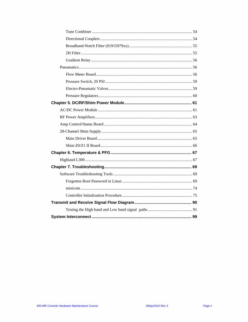
Tune Combiner .................................................................................................. 54
Directional Couplers .......................................................................................... 54
Broadband-Notch Filter (01915979xx) .............................................................. 55
2H Filter ............................................................................................................. 55
Gradient Relay ................................................................................................... 56
Pneumatics ............................................................................................................... 56
Flow Meter Board .............................................................................................. 56
Pressure Switch, 20 PSI ..................................................................................... 59
Electro-Pneumatic Valves .................................................................................. 59
Pressure Regulators ............................................................................................ 60
Chapter 5. DC/RF/Shim Power Module ............................................................ 61
AC/DC Power Module ............................................................................................ 61
RF Power Amplifiers ............................................................................................... 63
Amp Control/Status Board ...................................................................................... 64
28-Channel Shim Supply ......................................................................................... 65
Main Driver Board ............................................................................................. 65
Shim Z0/Z1 II Board .......................................................................................... 66
Chapter 6. Temperature & PFG ........................................................................ 67
Highland L300 ......................................................................................................... 67
Chapter 7. Troubleshooting .............................................................................. 69
Software Troubleshooting Tools ............................................................................. 69
Forgotten Root Password in Linux .................................................................... 69
minicom ............................................................................................................. 74
Controller Initialization Procedure ..................................................................... 75
Transmit and Receive Signal Flow Diagram ................................................... 90
Testing the High band and Low band signal paths ........................................... 91
System Interconnect ......................................................................................... 99

400-MR Console Hardware Maintenance Course 09Apr2010 Rev 3 Page iii
Table of Figures
Figure 1 – Digital Controllers in the Control Card Cage ................................................................................ 5 Figure 2 – Master Controller & Master Interconnection ................................................................................ 5 Figure 3 – Controller LEDs ............................................................................................................................ 6 Figure 4 – Generic Interconnection Board ..................................................................................................... 8 Figure 5 – Master Controller Interconnection ................................................................................................ 9 Figure 6 – Master Controller ........................................................................................................................ 10 Figure 7 – Master Controller Block Diagram ............................................................................................... 11 Figure 8 – RF Controller .............................................................................................................................. 12 Figure 9 – RF Controller Block Diagram ..................................................................................................... 13 Figure 10 – Dell Hub .................................................................................................................................... 25 Figure 11 – RF Boards when a synthesizer board is present ........................................................................ 26 Figure 12 – RF Boards when a VFS is present ............................................................................................. 27 Figure 13 Ref Gen 3 ..................................................................................................................................... 28 Figure 14 Synthesizer board ......................................................................................................................... 30 Figure 15 – Reference Generator 2 ............................................................................................................... 31 Figure 16 – Reference Generator Block Diagram ....................................................................................... 32 Figure 17 – 8-Way Splitter Block Diagram .................................................................................................. 33 Figure 18 – Transmitter Board ..................................................................................................................... 33 Figure 19 – RF Transmitter Block Diagram ................................................................................................. 34 Figure 20 – Two Channel Attenuator Board ................................................................................................ 35 Figure 21 – Four Channel Attenuator Switch Block Diagram ..................................................................... 36 Figure 22 – Lock Transceiver Board ............................................................................................................ 37 Figure 23 – Lock Transceiver 400 Block Diagram ...................................................................................... 38 Figure 24 – VFS Front .................................................................................................................................. 39 Figure 25 – VFS Block Diagram .................................................................................................................. 40 Figure 26 – PFE Board ................................................................................................................................. 42 Figure 27 -- PFE Block Diagram .................................................................................................................. 43 Figure 28 – Mixer Module ........................................................................................................................... 44 Figure 29 -- Mixer Module Block Diagram ................................................................................................. 45 Figure 30 – LO Selector ............................................................................................................................... 46 Figure 31 – Observe Preamps ....................................................................................................................... 47 Figure 32 -- High Band Preamp Schematics ................................................................................................ 48 Figure 33 – Observe Preamps ....................................................................................................................... 49 Figure 34 – Broad Band Preamp Schematic ................................................................................................. 50 Figure 35 -- Lock Preamp ............................................................................................................................. 51 Figure 36 -- Lock Preamp Schematic ........................................................................................................... 52 Figure 37 – Lock Diplexer ........................................................................................................................... 53 Figure 38 -- Lock Diplexer Schematic ......................................................................................................... 53 Figure 39 – Tune Combiner ......................................................................................................................... 54 Figure 40 – Directional Couplers ................................................................................................................. 54 Figure 41 – Broadband-Notch Filter ............................................................................................................ 55 Figure 42 – H2 Filter .................................................................................................................................... 55 Figure 43 -- Gradient Relay .......................................................................................................................... 56 Figure 44 – Flow Meter ................................................................................................................................ 57 Figure 45 – Flow meter schematic ............................................................................................................... 58 Figure 46 – 20psi pressure switch ................................................................................................................ 59 Figure 47 -- Electro-Pneumatic Valves ........................................................................................................ 59 Figure 48 – Regulators, top .......................................................................................................................... 60 Figure 49 – Regulators, bottom .................................................................................................................... 60 Figure 50 – Main Power Supply ................................................................................................................... 61 Figure 51 – DC Voltage Output ................................................................................................................... 62 Figure 52 – RF Power Amplifiers ................................................................................................................ 63

400-MR Console Hardware Maintenance Course 09Apr2010 Rev 3 Page iv
Figure 53 – RF Amplifier LED's .................................................................................................................. 63 Figure 54 – Amp Control/Status Board ........................................................................................................ 64 Figure 55 – Shim Boards .............................................................................................................................. 65 Figure 56 – Main Shim Driver Board ........................................................................................................... 66 Figure 57 -- Z0/Z1 Shim Board .................................................................................................................... 67 Figure 58 – L300 PFG & VT........................................................................................................................ 67 Figure 59 – PFG LED’s ................................................................................................................................ 68 Figure 60 – VT LEDs ................................................................................................................................... 68
400-MR Console Hardware Maintenance Course 09Apr2010 Rev 3 Page 1
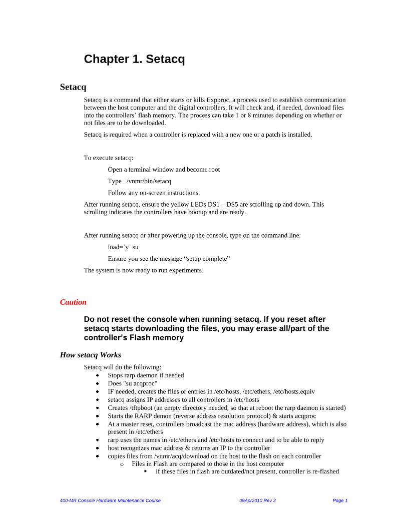
Chapter 1. Setacq
Setacq
Setacq is a command that either starts or kills Expproc, a process used to establish communication
between the host computer and the digital controllers. It will check and, if needed, download files
into the controllers’ flash memory. The process can take 1 or 8 minutes depending on whether or
not files are to be downloaded.
Setacq is required when a controller is replaced with a new one or a patch is installed.
To execute setacq:
Open a terminal window and become root
Type /vnmr/bin/setacq
Follow any on-screen instructions.
After running setacq, ensure the yellow LEDs DS1 – DS5 are scrolling up and down. This
scrolling indicates the controllers have bootup and are ready.
After running setacq or after powering up the console, type on the command line:
load=’y’ su
Ensure you see the message “setup complete”
The system is now ready to run experiments.
Caution
Do not reset the console when running setacq. If you reset after setacq starts downloading the files, you may erase all/part of the controller’s Flash memory
How setacq Works
Setacq will do the following:
Stops rarp daemon if needed
Does "su acqproc"
IF needed, creates the files or entries in /etc/hosts, /etc/ethers, /etc/hosts.equiv
setacq assigns IP addresses to all controllers in /etc/hosts
Creates /tftpboot (an empty directory needed, so that at reboot the rarp daemon is started)
Starts the RARP demon (reverse address resolution protocol) & starts acqproc
At a master reset, controllers broadcast the mac address (hardware address), which is also
present in /etc/ethers
rarp uses the names in /etc/ethers and /etc/hosts to connect and to be able to reply
host recognizes mac address & returns an IP to the controller
copies files from /vnmr/acq/download on the host to the flash on each controller
o Files in Flash are compared to those in the host computer
if these files in flash are outdated/not present, controller is re-flashed

400-MR Console Hardware Maintenance Course 09Apr2010 Rev 3 Page 2
flash will have these files and boot.ini
o setacq will show "downloading file X of 9" (X = 1- 9) files for several minutes
yellow leds on all controllers should be blinking in a unique pattern
PPC executes VxWorks and nvlib.o is loaded & executed into memory (thru
systemInit(0,1,1), see nvScript), then nvlib.o chooses the "flavor_exec.o" based on the
controller personality type bits
The controller’s FPGA is configured with that controller’s exec.o firmware
Any files in /tftpboot are deleted
Each controller's Flash now has ALL firmware for all controllers so a controller can be
put in any slot (lock and ddr are unique in hardware, but will function as a master, rf, pfg,
etc).

400-MR Console Hardware Maintenance Course 09Apr2010 Rev 3 Page 3
Note: It’s possible to ping any controller & could respond with “alive” (after vxWorks has
executed), since its network info is correct but may not have all necessary files to boot up.
Reset button:
At reset each controller's program (exec.o) is loaded into RAM from its flash memory, NOT from the host
computer and performs the following bootup cycle:
Controller boot Cycle:
1. Show the header file with MAC address as detected by type lines
2. Runs VxWorks
3. Requests IP# & name (RARP requests)
4. Runs nvScript (script that tells it to load nvlib.o & other boot files from flash) (nvScript.rd tells controller
to load boot files from /tftpboot)
5. Runs nvlib.o (program that tells it to read type lines & choose correct Xexec.o)
6. Correct Xexec.o file is opened to configure FPGA
7. FPGA is configured
8. Bootup completes
A full output of messages seen in the bootup of the master1 and ddr1 is located in the “Controller
Initialization” procedure in the trouble shooting section.

400-MR Console Hardware Maintenance Course 09Apr2010 Rev 3 Page 4
Chapter 2. Digital Controllers Section
Purpose
This section is about the digital controllers and the interconnection boards. It teaches you about
the controllers’ function, inputs/outputs, similarities/differences and bootup sequence.
Controllers & Interconnection Cards
Similarities and differences among the controllers:
There are 6 controllers boards plus interconnection cards in the digital section. Four are generic
controllers, one lock, and one receiver (DDR). The generic controllers are the master, RF, and
PFG controllers. All controllers have the same digital circuitry, but the lock and DDR have
mezzanine boards for the analog sections (ADC).
Similarities and differences among the interconnection cards:
All generic controllers are swappable. The DDR and lock can function as any generic controller,
but the generics cannot function as a lock or DDR.
All controllers, except master, use the Generic Interconnection Card (GIC). The GIC is swappable
with other GICs. The master uses the Master Interconnection Card (MIC). The MIC cannot be
swapped with a GIC.
The controller and its interconnection card are attached together. Both are installed as one piece
into the digital card cage. All controllers use the “Interconnection Card” to pass signals through to
the back plane. A controller’s function is fixed by its position in the card cage.
Technical Details:
Each controller contains a 24-bit timer, which sets the duration of each of the events that are
clocked out its own FIFO. Each FIFO bit has a timing resolution of 12.5 ns, with an 80MHz clock.
They each have their own processor running VxWorks that interfaces to the 100base T Ethernet
port.
Each controller has 64 MB RAM (DDR has 128MB), 16 MB Flash memory, the IBM Power PC,
and the FPGA chip. The flash memory stores all the firmware of all controllers. The controller
function is determined by the firmware programmed into the FPGA device as determined by its
slot position in the card cage.

400-MR Console Hardware Maintenance Course 09Apr2010 Rev 3 Page 5
List of boards:
Generic Interconnection Card
Master Interconnection Card
Master Controller
RF Controller
PFG Controller
Lock Controller
Receiver DDR Controller
Figure 1 – Digital Controllers in the Control Card Cage
Figure 2 – Master Controller & Master Interconnection
Master Controller
RF Controllers
#1 on right
Lock Controller
PFG Controller
DDR Controller
400-MR Console Hardware Maintenance Course 09Apr2010 Rev 3 Page 6
Denotation of LEDs
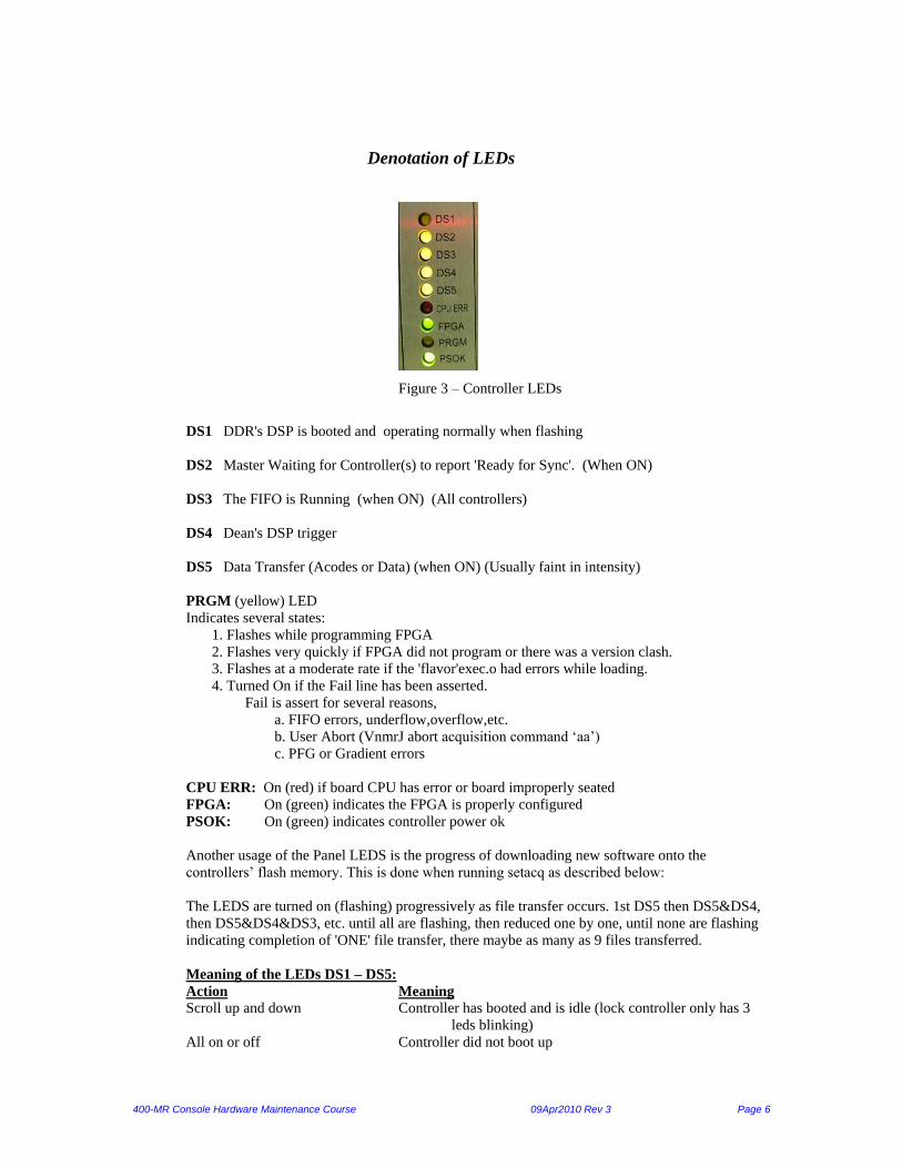
Figure 3 – Controller LEDs
DS1 DDR's DSP is booted and operating normally when flashing
DS2 Master Waiting for Controller(s) to report 'Ready for Sync'. (When ON)
DS3 The FIFO is Running (when ON) (All controllers)
DS4 Dean's DSP trigger
DS5 Data Transfer (Acodes or Data) (when ON) (Usually faint in intensity)
PRGM (yellow) LED
Indicates several states:
1. Flashes while programming FPGA
2. Flashes very quickly if FPGA did not program or there was a version clash.
3. Flashes at a moderate rate if the 'flavor'exec.o had errors while loading.
4. Turned On if the Fail line has been asserted.
Fail is assert for several reasons,
a. FIFO errors, underflow,overflow,etc.
b. User Abort (VnmrJ abort acquisition command ‘aa’)
c. PFG or Gradient errors
CPU ERR: On (red) if board CPU has error or board improperly seated
FPGA: On (green) indicates the FPGA is properly configured
PSOK: On (green) indicates controller power ok
Another usage of the Panel LEDS is the progress of downloading new software onto the
controllers’ flash memory. This is done when running setacq as described below:
The LEDS are turned on (flashing) progressively as file transfer occurs. 1st DS5 then DS5&DS4,
then DS5&DS4&DS3, etc. until all are flashing, then reduced one by one, until none are flashing
indicating completion of 'ONE' file transfer, there maybe as many as 9 files transferred.
Meaning of the LEDs DS1 – DS5:
Action Meaning
Scroll up and down Controller has booted and is idle (lock controller only has 3
leds blinking)
All on or off Controller did not boot up
400-MR Console Hardware Maintenance Course 09Apr2010 Rev 3 Page 7
Blinking pattern Setacq is downloading files into flash memory
Scrolling (during setacq) No files being downloaded as they should be due to an error
Blink towards center (master) Acquisition aborted
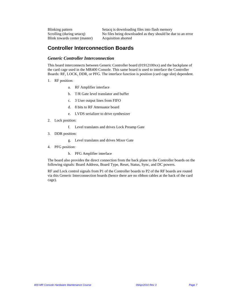
Controller Interconnection Boards
Generic Controller Interconnection
This board interconnects between Generic Controller board (01912100xx) and the backplane of
the card cage used in the MR400 Console. This same board is used to interface the Controller
Boards: RF, LOCK, DDR, or PFG. The interface function is position (card cage slot) dependent.
1. RF position:
a. RF Amplifier interface
b. T/R Gate level translator and buffer
c. 3 User output lines from FIFO
d. 8 bits to RF Attenuator board
e. LVDS serializer to drive synthesizer
2. Lock position:
f. Level translates and drives Lock Preamp Gate
3. DDR position:
g. Level translates and drives Mixer Gate
4. PFG position:
h. PFG Amplifier interface
The board also provides the direct connection from the back plane to the Controller boards on the
following signals: Board Address, Board Type, Reset, Status, Sync, and DC powers.
RF and Lock control signals from P1 of the Controller boards to P2 of the RF boards are routed
via this Generic Interconnection boards (hence there are no ribbon cables at the back of the card
cage).

400-MR Console Hardware Maintenance Course 09Apr2010 Rev 3 Page 8
Figure 4 – Generic Interconnection Board
Master Controller Interconnection
This board interconnects between Master Controller board and the backplane of the card cage used
in the Analytical and MR400 Console. It has the following functions:
Provides differential transceiver and level shifter to interface to the RF Front End
Provides differential transceiver and level shifter to interface to the pneumatic system
Provides differential transceiver and level shifter to interface to the shim system
Provides an entry point to Master Controller for External Trigger
Provide RS232 driver/receiver
Provides direct connections for the signals: Board address, Board Type, Reset, Status, Sync,
and powers

400-MR Console Hardware Maintenance Course 09Apr2010 Rev 3 Page 9
Figure 5 – Master Controller Interconnection
Controller Boards
Master Controller
The Master Controller provides the synchronizing signal that arms the other controllers –
essentially tells them when to start. See below for a brief overview of the Sync Bus. It contains
the controllers for serial ports, both RS-232 and SPI. The RF Front End control, VT Control, and
shim control, will reside on the Master Controller.
The master controls the pneumatics for liquids and contains the Lock Loop Filter Control
including the Lock/Hold and Homospoil signals.

400-MR Console Hardware Maintenance Course 09Apr2010 Rev 3 Page 10
Figure 6 – Master Controller
Sync Bus Signals Definitions:
Sync: differentially driven, originating from the Master Controller. Each controller is
programmed to wait “x” number of clock cycles before firing, where “x” is a number that
can be different from controller to controller. Upon the assertion of the sync signal to start
the experiment, each controller will start counting cycles on the next active edge of the
clock.
Fail: causes a system shutdown, board that asserts the line will broadcast a message (if
possible).
Warning: each controller is programmed how to respond to an active Warning signal, board
that asserts the line should broadcast a message.
Reset: originates from the Master, puts other modules into “safe” state.
FPGA
PPC
Flash

400-MR Console Hardware Maintenance Course 09Apr2010 Rev 3 Page 11
Figure 7 – Master Controller Block Diagram
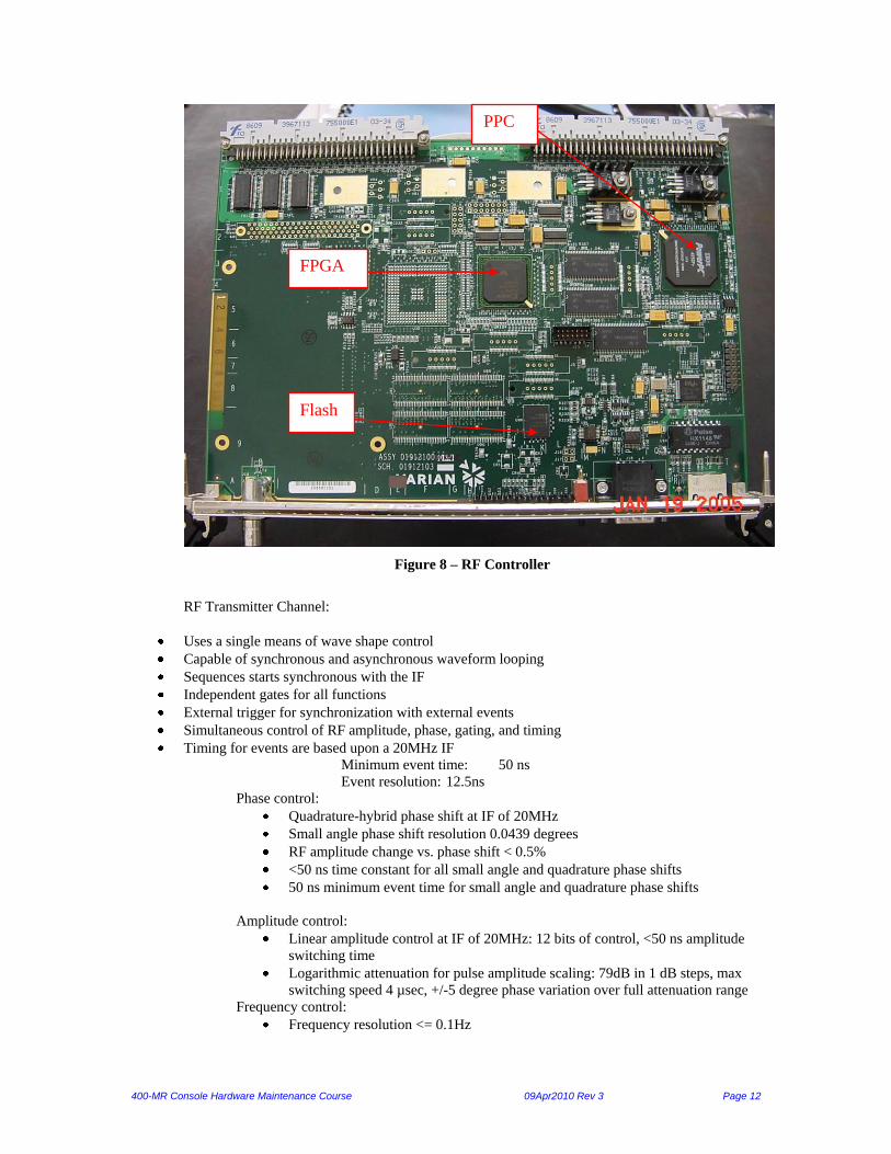
RF Controller
The RF Controller (up to 2) provides all the controlling signals required to run an RF transmitter
channel – the timing gates, the amplitude and phase for the RF transmitter and attenuator, the
control for the LO synthesizer. This controller contains in hardware (outside of the processor) a
linear phase adder and an amplitude multiplier so that it saves processor time in stuffing the FIFO.
This Auxiliary bus is for communication with synthesizers, attenuators, and possibly as a source
for more user output lines.
400-MR Console Hardware Maintenance Course 09Apr2010 Rev 3 Page 12
Figure 8 – RF Controller
RF Transmitter Channel:
Uses a single means of wave shape control
Capable of synchronous and asynchronous waveform looping
Sequences starts synchronous with the IF
Independent gates for all functions
External trigger for synchronization with external events
Simultaneous control of RF amplitude, phase, gating, and timing
Timing for events are based upon a 20MHz IF
Minimum event time: 50 ns
Event resolution: 12.5ns
Phase control:
Quadrature-hybrid phase shift at IF of 20MHz
Small angle phase shift resolution 0.0439 degrees
RF amplitude change vs. phase shift < 0.5%
<50 ns time constant for all small angle and quadrature phase shifts
50 ns minimum event time for small angle and quadrature phase shifts
Amplitude control:
Linear amplitude control at IF of 20MHz: 12 bits of control, <50 ns amplitude
switching time
Logarithmic attenuation for pulse amplitude scaling: 79dB in 1 dB steps, max
switching speed 4 µsec, +/-5 degree phase variation over full attenuation range
Frequency control:
Frequency resolution <= 0.1Hz
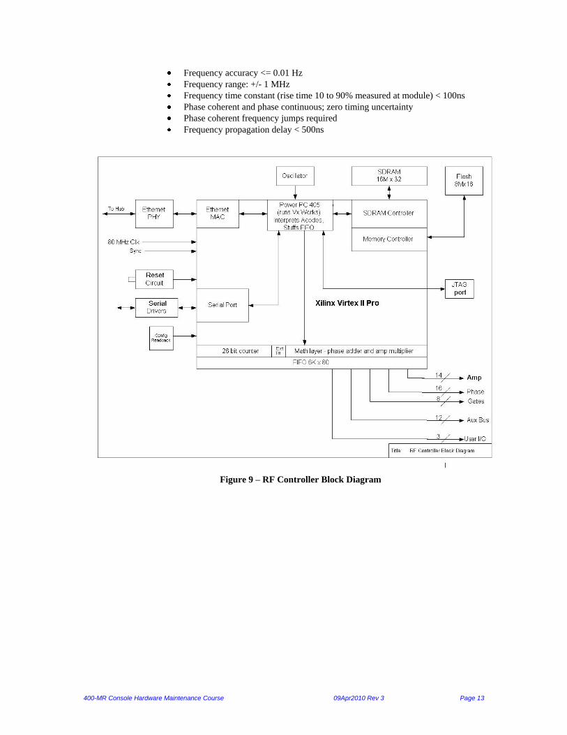
FPGA
PPC
Flash
400-MR Console Hardware Maintenance Course 09Apr2010 Rev 3 Page 13
Frequency accuracy <= 0.01 Hz
Frequency range: +/- 1 MHz
Frequency time constant (rise time 10 to 90% measured at module) < 100ns
Phase coherent and phase continuous; zero timing uncertainty
Phase coherent frequency jumps required
Frequency propagation delay < 500ns
Figure 9 – RF Controller Block Diagram

400-MR Console Hardware Maintenance Course 09Apr2010 Rev 3 Page 14
PFG Controller
Part Number - 01-912100-00
Schematic Number - 01-912103-00
The PFG Controller is a generic controller. It’s output bits mate with the L630 VT/PFG
module.
PFG Controller
FPGA
PPC
Flash

400-MR Console Hardware Maintenance Course 09Apr2010 Rev 3 Page 15
The PFG Controller FPGA Specifications:
Designed to Interface to PFG Amplifiers:
400-MR:
L630: Single axis 3A channel unit (VT/PFG module)
VnmrS:
L650: New 10A single channel unit (with and without ECC) – Amp_Type:0
L200: Three Axis 20A unit (only allow 10A output and no ECC) – Amp_Type:1
L500: Single Axis 100A single channel unit (no ECC) – Amp_Type:2
Controller will not interface to the L600 amplifier
Waveform Generation and other features incorporated into Controller FPGA Math Layer:
16-bit amplitudes (Amp) and scaling (AmpScale) factors for X,Y and Z
waveforms
Auto-incrementing functionality for Amp and AmpScale for all 3 waveforms
(program multiple steps with an increment value and then burst-write to FIFO)
FIFO outputs serialized at 10 MHz in-line with update rate of DACs in amplifiers
Readback capability for FIFO-Controlled outputs
Maximum Integrated Area Gradient Pulse Calculations
Controller Outputs:
GPIO: XEnable,YEnable, ZEnable, Reset_Amps, XOK, YOK, ZOK, Amp_Type,
PFG_On, Address
20-bit FIFO Outputs: XAmp,YAmp, ZAmp – serialized at 10MHz with clock
and strobe
1-bit FIFO Output: PFG_User
20-bit GPIO: XEcc, YEcc, ZEcc – serialized at 10MHz with clock and strobe
Eddy Current Compensation:
Choose ECC Option via Address Lines
Send 20-bit GPIO data with clock and strobe (L650 only)
The 20-bit data contains the Range Selected and Data Value
Communication Protocol for L650/L200/L500 PFG Amplifiers:
20-bit serial data
o 16-bit significant data
o Twos complement, MSB first
o 4-bit dummy bits at end
Communication Protocol for L650/L200/L500 PFG Amplifiers (continued):
10 MHz clock, 20 rising clock edges
Strobe pulse 40ns after 20th clock falling edge
Strobe pulse 25 ns pulse width
Address Lines <A2A1A0> : 000 main Gradient and 001 ECC (L650 only)

400-MR Console Hardware Maintenance Course 09Apr2010 Rev 3 Page 16
ECC Range Selection and Value Adjustments (L650 only)
o 20 bit serial data with 10 MHz clock and ending strobe
o Bits 16:19 are item identified, MSB first
o Five (5) millisecond delay between communication of ECC data
L650 only:
Identifier (19:16) Item Selected Baseline Value
0 ECC1 tau 25 usec
1 ECC1 amplitude 0.35
2 ECC2 tau 180 usec
3 ECC2 amplitude 0.12
4 ECC3 tau 180 usec
5 ECC3 amplitude 0.12
6 ECC4 tau 1.5 ms
7 ECC4 amplitude 0.035
o Time Constants: 12-bits, unsigned in bits 11:0
o Given a baseline minimum time constant of K seconds, and a console
numeric amplitude factor of N (N ranging from 0 to 4095), the actual
time constant will be:
Tau = K*4096/(4096-N) where the maximum N is 3891, corresponding
to Tau = 20 * K.
o Amplitudes: 13-bits, 12th bit is sign, bits 11:0 are the magnitude M.
o If sign bit is 0, ECC will be positive, giving rise to an overshoot on a
current step
o Given a baseline minimum amplitude of M, and a console numeric
amplitude factor of M (M ranging from 0 to 4095), the actual
overshoot/undershoot will be: A =B * M / 4096
ECC On/Off: currently settable from the front panel (ECC Available only with
L650)
o Console control via Identifier code F with the LSB (bit 0 of the 20 bit
word)
o LSB set to 1 for ECC on and cleared to 0 to turn ECC off

400-MR Console Hardware Maintenance Course 09Apr2010 Rev 3 Page 17
Lock Controller
Part Number - 01-912140-00
Schematic Number - 01-912103-02
The Lock Controller provides the control for all the lock gain, phase, amplitude, and
gating, as well as generating with a DDS, a lock offset signal for the Lock Transceiver
board. The Lock Controller is tasked to perform all these functions plus contain a lock
ADC that can be controlled synchronous with the experiment.
Lock Controller Board

400-MR Console Hardware Maintenance Course 09Apr2010 Rev 3 Page 18
Functional Requirements (in addition to the generic requirements):
DDS (AD9852) for generating lock offset frequency
Two ADCs (LTC1608) for acquiring quadrature lock signal
Pulse Rate and Width Controller
FIR filter for lock signal
1K-point FFT (optional)
Special I/O Requirements:
Sync(Input): Differential pair, TTL levels
Minimum Pulse 50ns
Resolution 12.5ns
Setup time: Sync rising edge to Clock rising edge>
2 ns
Analog I/O Requirements:
Offset Frequency (Output): Sinewave, SFDR > 50 dBc
Freq Range: 5 – 15 MHz
Amplitude: > 4 dBm
Resolution: < 0.01 Hz
Lock Signal I and Q (2 Inputs): Max. Input: 2.5Vpp
Filter: 4-Pole Butterworth Low-pass, fc = 100 KHz
LED Designations: ADC Overflow
Dual Port RAM:
32Kx16 dual port SRAM is used for storing the data from two ADCs, 16Kx16 for each channel. Virtex II
Pro’s Block SelectRAM is employed for the dual port RAM. One port is for data write-in and the other for
read-out.
Interfaces to DDS and ADCs:
The interface between Virtex and DDS (AD9852) needs to handle the data bus (8-bit), address bus (6-bit),
reset, write (WRB), and data transfer (UD). Most of registers in AD9852 are more than 8 bits, therefore,
their setting needs multiple writes.
The Virtex interface to LTC1608 needs to generate sampling pulse (CTC) and convert pulse (CONV) to
control two ADC chips. Virtex also generates RAM address (15-bit) and write pulse to write the data to
dual port RAM. The logic should handle BUSY and OVF signals as well.
Functional Descriptions:
1. Pulse Rate and Width Controller

400-MR Console Hardware Maintenance Course 09Apr2010 Rev 3 Page 19
TX
RV
t1 t2 t3 t4
CTC
t5
N pulses
The lock pulse sequence is illustrated as above. The controller generates three outputs: transmitter gate
(TX), receiver gate (RV), and ADC convert pulses (CTC). TX and RV go to P2 connector to the
backplane, and CTC is sent to on board ADCs. Parameters t1, t2, …, t5, and N (number of sampling
points) are configurable by PPC. CTC should be synchronized to receiver gate.
Range of parameter values:
Sequence repetition frequency (1/T) = 2 KHz, 20 Hz, and 1 Hz;
t1 / T = 1%;
t2 / T = 1 – 16%;
t3 / T = 1%;
1 / t5 = 2 – 5 KHz.
(T = t1 + t2 + t3 + t4)
2. FIR Filter
The data acquired by ADC needs to be filtered by embedded FIR filter. The coefficients are loadable by
PPC. The maximum number of coefficients is 256. Four FIR filters are needed for different purposes.
3. 1K-point FFT
The 1K-point embedded FFT is for lock signal searching. This is an option if the FPGA resource is enough.
4. A Table for All Control Signals
Control Width Offset Interface Meaning Notes
Receiver gain 8 0 gpio -out linear gain of lock
receiver
Sent to xcvr
Transmitter phase 8 2 gpio - out 360/256 * value Sent to xcvr
Transmitter power 8 4 gpio - out xmit power setting Sent to xcvr
Lock frequency 48 12 gpio - out 5-50 Mhz with < 0.01 Hz
res.
TBD
Lock rate 2 16 gpio - out 2 lsb composite word 1 Hz, 20 Hz,
2kHz

400-MR Console Hardware Maintenance Course 09Apr2010 Rev 3 Page 20
Control Width Offset Interface Meaning Notes
Lock TX pulse
duty
4 16 gpio - out 4 lsb composite word 1-16%
ADC data current
pointer
32 TBD dual port
ram
last adc point
ADC data array 32 X 2K TBD dual port
ram
lock data for display
ADC 45 Hz abs 32 20 gpio - in FID absorption for status
display
ADC 45 Hz
dispersion
32 24 gpio -in FID dispersion for status
display
ADC data
amplitude
32 28 gpio -in lock lost detect Optional
ADC data FFT 32 32 gpio -in lock direction detect Optional
Lock Controller Block Diagram

400-MR Console Hardware Maintenance Course 09Apr2010 Rev 3 Page 21
Receiver DDR Controller
Part Number - 01-912160-00
Schematic Number - 01-912103-03
The DDR contains two PCB assemblies, a DDR-D board (has the same functionality as
the other generic controllers plus digital signal processing which is unique to this
controller) and a DDR-A mezzanine. The DDR-A mezzanine directly digitizes the
20MHz IF signal from the Mixer/Receiver. The DDR-A mezzanine board contains the
80MHz ADC (14 bit) that is used to directly digitize the 20MHz IF frequency obtained
from the mixer. The output of this is fed into a DSP chip that performs digital filtering
and down-sampling to a 5MHz bandwidth. The output of this goes to a second DSP chip
that performs more digital filtering and down-sampling direct to the spectral window
(“sw”) with an effective 20-bit resolution. This direct IF detection removes the need for
quadrature detection, since signal frequencies are all positive and there is no confusion as
to which “side” of the
carrier frequency is
correct.
The digitized data is
processed by selectable
digital filters occurs on
the DDR-D board. The
final data is sent via
Ethernet back to the
host. In conjunction
with the GIC, the DDR
controls the Receiver
Gate.
DDR Controller Board
400-MR Console Hardware Maintenance Course 09Apr2010 Rev 3 Page 22
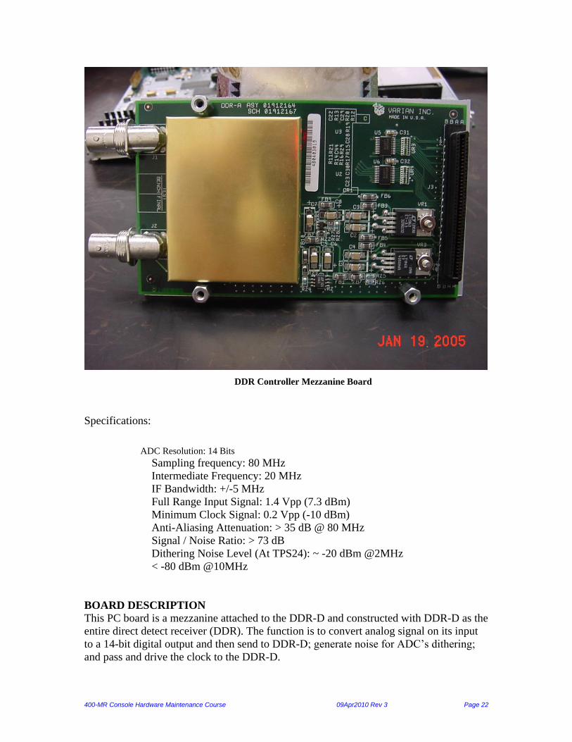
DDR Controller Mezzanine Board
Specifications:
ADC Resolution: 14 Bits
Sampling frequency: 80 MHz
Intermediate Frequency: 20 MHz
IF Bandwidth: +/-5 MHz
Full Range Input Signal: 1.4 Vpp (7.3 dBm)
Minimum Clock Signal: 0.2 Vpp (-10 dBm)
Anti-Aliasing Attenuation: > 35 dB @ 80 MHz
Signal / Noise Ratio: > 73 dB
Dithering Noise Level (At TPS24): ~ -20 dBm @2MHz
< -80 dBm @10MHz
BOARD DESCRIPTION
This PC board is a mezzanine attached to the DDR-D and constructed with DDR-D as the
entire direct detect receiver (DDR). The function is to convert analog signal on its input
to a 14-bit digital output and then send to DDR-D; generate noise for ADC’s dithering;
and pass and drive the clock to the DDR-D.

400-MR Console Hardware Maintenance Course 09Apr2010 Rev 3 Page 23
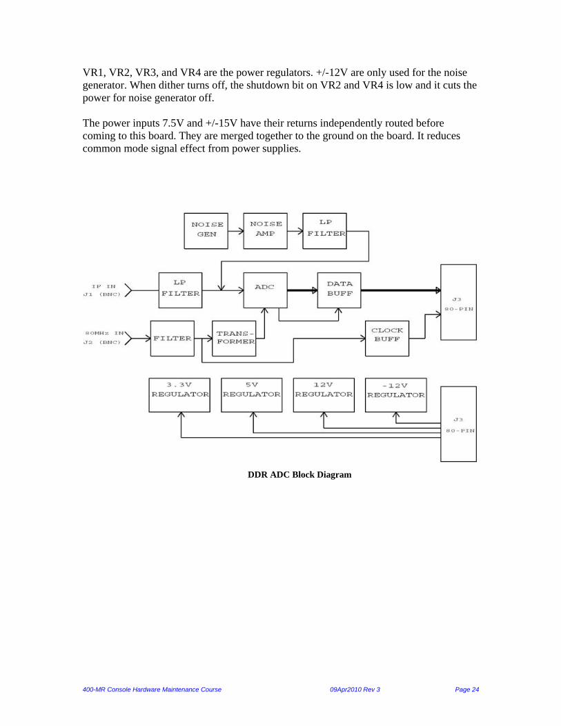
Block Diagram (Page 1)
J1 is the input signal and goes through a low pass anti-aliasing filter to the ADC input.
The ADC output goes to a buffer driving J3. J2 is the 80MHz clock input. A transformer
converts the single-ended signal to differential for ADC’s requirement. In the other hand,
the input clock is the clock source driving DDR-D. A buffer between ADC and J3 is not
only for the clock driver but also for the isolation between analog part and digital part.
The top three blocks are the noise generator. The noise gets amplified and filtered to
reach a certain level and frequency profile, and then feeds to the ADC input.
The bottom blocks are four power regulators supplying to ADC and noise generator.
Analog-To-Digital Converter (Page 2)
L3, L2, L1, C11, C9, and construct a low-pass filter. The cut-off frequency is 25MHz (-
1dB) for the receiver bandwidth from 15MHz to 25MHz. The low end of the filtering
characteristic is achieved by DSP in the DDR-D. T2 is a 1:4 transformer and converts the
single end signal to differential. R1, R2, R4, and the AD6645, U4, input impedance (1K)
makes the secondary impedance of T2 to 200. R1 and R2 are the isolation resistors
between T2 and AD6645, and recommended by AD6645 data sheet.
U5 and U6 latch the data and drive the data bus to DDR-D. The latch clock is from
AD6645’s data ready (DRY) signal. The data buffer also isolates the ADC from any
noise coming from DDR-D. UR1 to UR4 are the damping resistor networks for driving
the long traces and the isolation as well.
T3 is an EMI filter to reduce the common mode signal. T1 is a 1:4 transformer. It
converts the clock to differential for the AD6645’s input. R3 is for the impedance match.
U1 is a clock buffer, which drives 80MHz clock in PECL type for DDR-D required.
The ADC, transformer, and the input filter are the sensitive components to
electromagnetic field. A shielding box covering these components could reduce any noise
from outside. The clock purity is very important as well. To avoid the interference
between ADC input circuitry and clock part, a shielding fence is used to separate two
parts.
Noise Generator and Power Regulators (Page 3)
CR1 is a noise diode. The white noise is amplified by U2 and U3, and then filtered by
FL1 to cut off the frequency above 5MHz. The noise at FL1’s output (TPS24) should be
lower than -80 dBm at 15MHz to avoid the noise entering to the IF band (15 – 25 MHz).
The filtered noise then is fed to the ADC input by a divider (R7 and R8) for dithering.
The dither can be turn on or off by software.
The dithering part is shielded to prevent the noise EMI. There are fences isolated from
ADC and clock parts.
400-MR Console Hardware Maintenance Course 09Apr2010 Rev 3 Page 24
VR1, VR2, VR3, and VR4 are the power regulators. +/-12V are only used for the noise
generator. When dither turns off, the shutdown bit on VR2 and VR4 is low and it cuts the
power for noise generator off.
The power inputs 7.5V and +/-15V have their returns independently routed before
coming to this board. They are merged together to the ground on the board. It reduces
common mode signal effect from power supplies.
DDR ADC Block Diagram
400-MR Console Hardware Maintenance Course 09Apr2010 Rev 3 Page 25
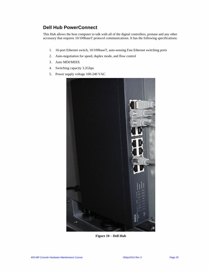
Dell Hub PowerConnect
This Hub allows the host computer to talk with all of the digital controllers, protune and any other
accessory that requires 10/100baseT protocol communications. It has the following specifications:
1. 16-port Ethernet switch, 10/100baseT, auto-sensing Fast Ethernet switching ports
2. Auto-negotiation for speed, duplex mode, and flow control
3. Auto MDI/MDIX
4. Switching capacity 3.2Gbps
5. Power supply voltage 100-240 VAC
Figure 10 – Dell Hub

400-MR Console Hardware Maintenance Course 09Apr2010 Rev 3 Page 26
Chapter 3. RF
RF Boards
The RF boards are used to generate RF pulses for observe, decouple, and lock frequencies.
The following RF boards are present when a synthesizer board is present, not a Varian Frequency
Synthesizer (VFS):
a) Reference Generator 3
b) Synthesizer
c) Transmitter Boards (2 only)
d) 2-Channel Attenuator
e) Lock Transceiver
Figure 11 – RF Boards when a synthesizer board is present
Ref Gen 3
Transmitters
Lock Transceiver
2-Channel Attenuator
Synthesizer board

400-MR Console Hardware Maintenance Course 09Apr2010 Rev 3 Page 27
The following RF boards are present when a Varian Frequency Synthesizer (VFS) is present
inside the console.
f) Reference Generator
g) Transmitter Boards (2 only)
h) 2-Channel Attenuator
i) Lock Transceiver
Figure 12 – RF Boards when a VFS is present
Lock Transceiver
Reference Generator
Transmitters
2-Channel Attenuator
400-MR Console Hardware Maintenance Course 09Apr2010 Rev 3 Page 28
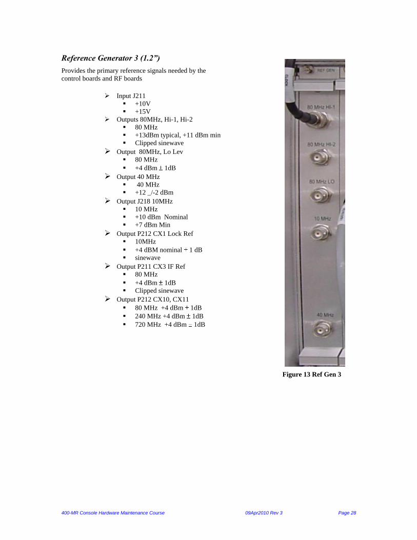
Reference Generator 3 (1.2”)
Provides the primary reference signals needed by the
control boards and RF boards
Input J211
+10V
+15V
Outputs 80MHz, Hi-1, Hi-2
80 MHz
+13dBm typical, +11 dBm min Clipped sinewave
Output 80MHz, Lo Lev 80 MHz +4 dBm 1dB
Output 40 MHz 40 MHz +12 _/-2 dBm
Output J218 10MHz 10 MHz +10 dBm Nominal +7 dBm Min
Output P212 CX1 Lock Ref 10MHz +4 dBM nominal 1 dB sinewave
Output P211 CX3 IF Ref 80 MHz +4 dBm 1dB Clipped sinewave
Output P212 CX10, CX11 80 MHz +4 dBm 1dB 240 MHz +4 dBm 1dB 720 MHz +4 dBm 1dB
Figure 13 Ref Gen 3

400-MR Console Hardware Maintenance Course 09Apr2010 Rev 3 Page 29
Figure 14 Ref Gen 3 Block Diagram

400-MR Console Hardware Maintenance Course 09Apr2010 Rev 3 Page 30
Synthesizer Board
Power Requirements
11V +/- 0.3
5V +/- 0.3
Outputs CH1, CH2
36 MHz – 422 MHz
+12.5 dBm Input Reference Frequencies from Ref Gen 3
80/240/720 MHz
4dBm/4dBm/3dBm
LEDs Ch1, Ch2
Green: CPLD chip present
Yellow: never on (no meaning)
Figure 14 Synthesizer board

400-MR Console Hardware Maintenance Course 09Apr2010 Rev 3 Page 31
Reference Generator 2 (1.2”)
Provides the primary reference signals
needed by the control boards and RF
boards
Input J211
+10V
+15V
Output J213 80MHz, Hi Lev
80 MHz
+13dBm typical Clipped sinewave
Output P212 CX1 Lock Ref 10MHz +4 dBM nominal 1 dB sinewave
Output P211 CX3 IF Ref 80 MHz +4 dBm 2dB Clipped sinewave
Output J215 80MHz, Lo Lev 80 MHz +4 dBm 1dB
Output J218 10MHz 10 MHz +10 dBm Nominal +7 dBm Min
Figure 15 – Reference Generator 2
400-MR Console Hardware Maintenance Course 09Apr2010 Rev 3 Page 32
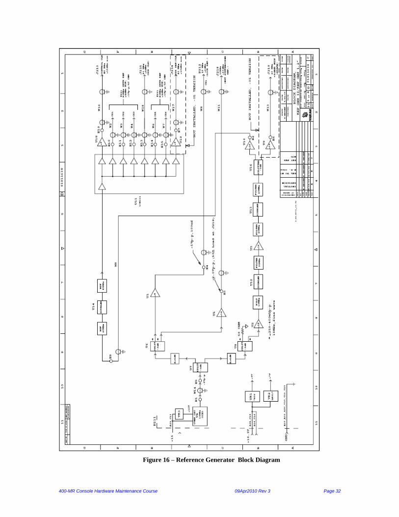
Figure 16 – Reference Generator Block Diagram
400-MR Console Hardware Maintenance Course 09Apr2010 Rev 3 Page 33
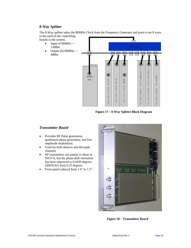
8-Way Splitter
The 8-Way splitter takes the 80MHz Clock from the Frequency Generator and ports it out 8 ways
to the each of the controlling
boards in the system.
Input of 80MHz: ~
13dBm
Output (8) 80MHz: ~
4dBm
Figure 17 – 8-Way Splitter Block Diagram
Transmitter Board
Provides RF Pulse generation,
quadrature phase generation, and fine
amplitude modulation.
Used for both observe and decouple
channels
RF transmitters are similar to those in
INOVA, but the phase-shift resolution
has been improved to 0.0439 degrees
(360/8192) from 0.25 degrees. Front panel reduced from 1.6” to 1.2”.
Figure 18 – Transmitter Board

400-MR Console Hardware Maintenance Course 09Apr2010 Rev 3 Page 34
Figure 19 – RF Transmitter Block Diagram
400-MR Console Hardware Maintenance Course 09Apr2010 Rev 3 Page 35
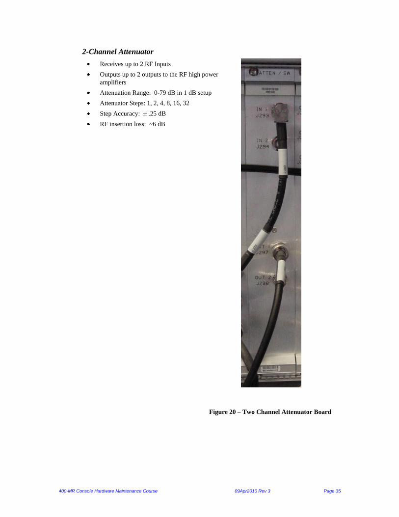
2-Channel Attenuator
Receives up to 2 RF Inputs
Outputs up to 2 outputs to the RF high power
amplifiers
Attenuation Range: 0-79 dB in 1 dB setup
Attenuator Steps: 1, 2, 4, 8, 16, 32
Step Accuracy: .25 dB
RF insertion loss: ~6 dB
Figure 20 – Two Channel Attenuator Board

400-MR Console Hardware Maintenance Course 09Apr2010 Rev 3 Page 36
Figure 21 – Four Channel Attenuator Switch Block Diagram
400-MR Console Hardware Maintenance Course 09Apr2010 Rev 3 Page 37
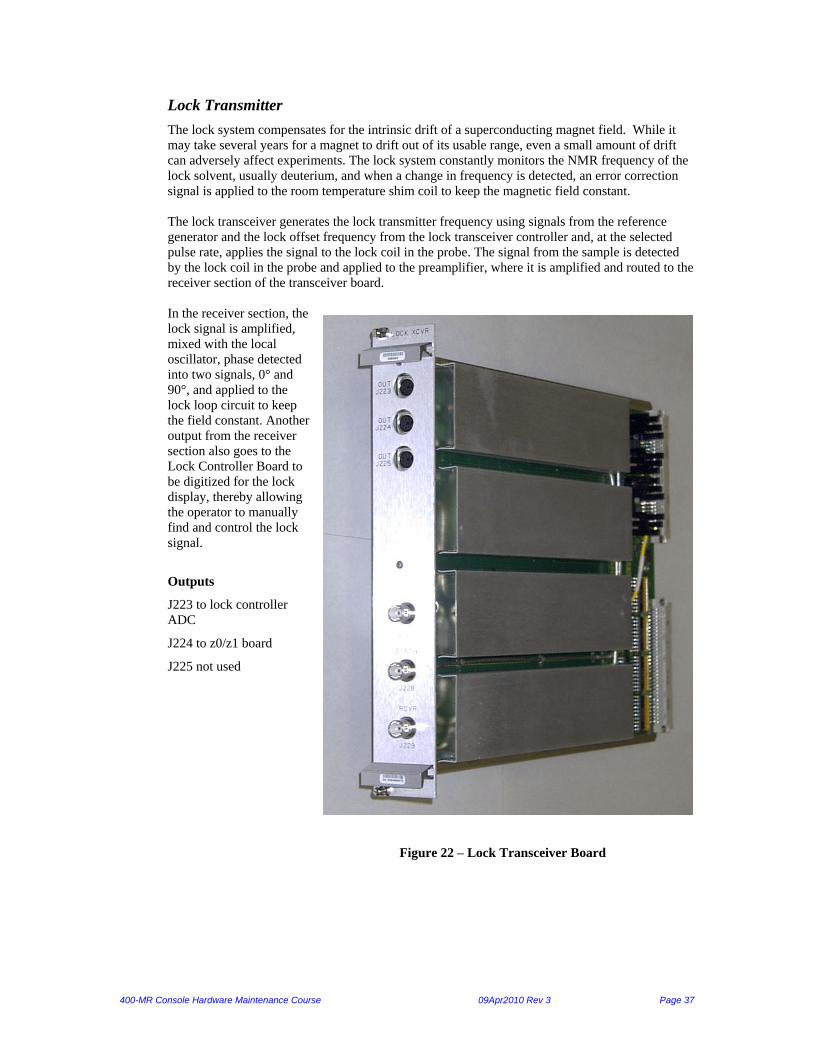
Lock Transmitter
The lock system compensates for the intrinsic drift of a superconducting magnet field. While it
may take several years for a magnet to drift out of its usable range, even a small amount of drift
can adversely affect experiments. The lock system constantly monitors the NMR frequency of the
lock solvent, usually deuterium, and when a change in frequency is detected, an error correction
signal is applied to the room temperature shim coil to keep the magnetic field constant.
The lock transceiver generates the lock transmitter frequency using signals from the reference
generator and the lock offset frequency from the lock transceiver controller and, at the selected
pulse rate, applies the signal to the lock coil in the probe. The signal from the sample is detected
by the lock coil in the probe and applied to the preamplifier, where it is amplified and routed to the
receiver section of the transceiver board.
In the receiver section, the
lock signal is amplified,
mixed with the local
oscillator, phase detected
into two signals, 0° and
90°, and applied to the
lock loop circuit to keep
the field constant. Another
output from the receiver
section also goes to the
Lock Controller Board to
be digitized for the lock
display, thereby allowing
the operator to manually
find and control the lock
signal.
Outputs
J223 to lock controller
ADC
J224 to z0/z1 board
J225 not used
Figure 22 – Lock Transceiver Board

400-MR Console Hardware Maintenance Course 09Apr2010 Rev 3 Page 38
Figure 23 – Lock Transceiver 400 Block Diagram

400-MR Console Hardware Maintenance Course 09Apr2010 Rev 3 Page 39
Varian Frequency Synthesizer (VFS)
The VFS is also called the DDS-based frequency synthesizer. It can be used with either the Ref
Gen 2 (which has 3 ports) or Ref Gen 3 (which has 5 ports) boards. On newer 400-MR systems,
the VFS has been replaced by a synthesizer board, which also requires the Ref Gen 3.
It runs off AC power and takes a 10MHz reference clock input. The output frequencies range from
46 MHz to 620.5 MHz. The VFS can be configured to have up to four identical output channels,
but the one in this console only has 2 channels. This is done by using two “channel boards” to
populate the unit. The VFS is controlled via a serial interface from the RF controllers of each
channel. There is also a USB interface on the front of the unit for standalone operation and
diagnostics.
Figure 24 – VFS Front
VFS Specifications:
1. Frequency Accuracy
Locked to 10MHz Reference
2. Frequency Resolution
0.1 Hz
3. Frequency Reference Input
10 MHz
+4dBm to +10dBm
50 ohms impedance
4. Frequency Output Level
+8dBm to +19dBm

400-MR Console Hardware Maintenance Course 09Apr2010 Rev 3 Page 40
Figure 25 – VFS Block Diagram

400-MR Console Hardware Maintenance Course 09Apr2010 Rev 3 Page 41
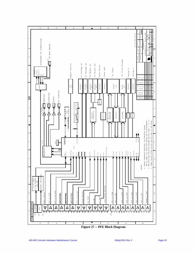
Chapter 4. Pneumatics Front End The Pneumatics/Front End (PFE) module provides the control and routes the following; Ethernet
connections, RF signals, and system pneumatics. It also provides both pressure and flow safety
when using variable temperature.
RF Front End
The RF Front End has the following components inside of the drawer:
6. Pneumatics Front End (PFE) board
7. Mixer
8. LO Selector
9. High Band Preamp
10. Low Band Preamp
11. Lock Preamp
12. Lock Diplexer
13. Tune Signal Combiner
14. Directional couplers (DC)
15. Flow Meter board
16. Broadband-Notch Filter
17. 2H Filter
PFE Board
The PFE board is connected via J1 (26 pin High-Density D-Sub) that connects to J4 on the
backplane, its function is the control of the Pneumatics, all signals are then routed to the
MIC/Master slot of the card cage.
The upper barrel is connected via J7 (15 pin D-sub Female). J7 is compatible with the current low
field, High field and Hermes style of upper barrel. Provision has been made to light two LED’s on
top of the upper barrel together with a manual eject switch. One Led will show if a sample is
present at the bottom of the upper barrel, the other will give an indication if the sample is
spinning. Pin 13 is reserved as a new generation upper barrel detect. Pin 13 is normally pulled
high, when a new upper barrel becomes available, this pin will be shorted to ground so that the
Pneumatics box can detect its presence.

400-MR Console Hardware Maintenance Course 09Apr2010 Rev 3 Page 42
NOTE:
Refer to the 400-MR Tech Support website for the latest updates on the PFE module including the
service bulletin: “MP200808 N15 / Lock Issues”
The MIC board communicates to the CPLD via two SPI protocols, one for the Pneumatics portion
of the board (J1), the other for the RF Front End portion of the board (J4).
The Pneumatics functions of the CPLD are:
Observe the position of the flow ball within the VT flow meter, set a visual indication of flow
limit thresholds
Disable the VT controller if the VT flow goes out of tolerance
Create an error signal that the console can use to stop the experiment and blank the RF
amplifiers
Monitor via an air pressure switch, if the gas supply falls below 20 psi
Determine what type of upper barrel is connected to the system
Monitor the power supply via a voltage comparator circuit
The “flasher” circuit of U10 produces a ca 1Hz square pulse, which is used to flash the set bit lines
of the VT flow meter in the event of VT flow fault. (This gives a visual indication in the event that
the VT gas flow returns before the end user has noticed the fault).
The RF Front End functions of the CPLD are:
To set the lock attenuator bit (20db) and “lock_H_L” (high band lock only) bit
Set the input and gain
stages for the mixers
Select which preamp
gets the T/R gate
Select which preamp
gets power (+12V)
Logic decode for
relays
Read the board ID
bits (set by Resistors
R51, R52, R53 and
R54)
Figure 26 – PFE Board
400-MR Console Hardware Maintenance Course 09Apr2010 Rev 3 Page 43
Figure 27 -- PFE Block Diagram

400-MR Console Hardware Maintenance Course 09Apr2010 Rev 3 Page 44
LEDs:
DS1: RFFE write
DS2: RFFE read
DS3: Pneumatic read
DS4: Pneumatic write
DS5: T/R gate
DS6: Power OK
DS7: Sample bottom
Mixer
The Mixer module takes input from the LO selector and FID riding on the RF carrier signal input
to produce the FID riding on the IF carrier of 20 MHz. It also directs the lock fid back to the DDR
when observing the lock frequency using tn=lk. This is also, where all of the gain happens for the
DDR.
Frequency range of the mixer depends on which SSB is used.
High Band = 350-950 MHz
Broad Band = 6-400 MHz
Figure 28 – Mixer Module

400-MR Console Hardware Maintenance Course 09Apr2010 Rev 3 Page 45
Figure 29 -- Mixer Module Block Diagram

400-MR Console Hardware Maintenance Course 09Apr2010 Rev 3 Page 46
LO Selector
The LO Selector has two inputs from each of the two transmitters. These inputs are that of the LO
frequency depending on what the tn and dn are set to. The selector selects which transmitter’s LO
to send to the mixer. The master controller sends the signal to the selector for the switching of the
transmitters’ LO is going to be the observe transmitter.
Inputs:
DC+: +5V from J5 on the backplane
DC-: -15V from J5 on the backplane is converted to –5V by a zener diode in the cable itself
TTL: 0V to select the high band L.O. and 5V to select the low band L.O.
Figure 30 – LO Selector
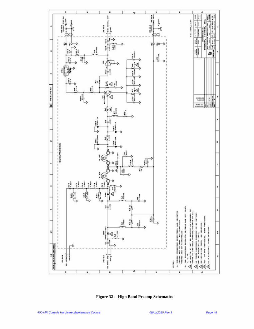
High Band Preamp
This preamp module operates in 375-405 MHz range. It contains an active T/R switch, a low noise
preamplifier, and a probe input filter. The “T” portion of the switch sends the transmitter RF
power to the ‘probe’ line with low loss (< .5 dB typically) during transmits intervals, and blocks
transmitter noise (attenuation >30 dB typically) during receive intervals. To avoid degrading the

400-MR Console Hardware Maintenance Course 09Apr2010 Rev 3 Page 47
preamp noise figure, the transmitter input source (e.g. power amplifier) must be ‘off’ during
receive mode, with residual excess noise <20 dB.
The “R” portion of the T/R switch uses a quarter-wave cable and active shunt diode to isolate the
transmitter probe line during transmit mode, and to reduce the RF power level to the preamp. That
level is further reduced (and some protection provided against switch failures and misconnections)
by an additional quarter-wave line and passive shunt diodes. During receive mode, probe input
signal is connected to the preamp input with low loss (.2 dB typ.) and amplified by ~30 dB. The
preamp overall noise figure is 0.8 dB ±0.2 dB, and it recovers from T/R gating and RF overloads
in <1 ms. The preamp output capability is at least 20 dB greater than input capacity of following
amplifier/mixer stages, so an attenuator in the mixer box will be activated at maximum signal
levels.
The high pass probe input filter has several functions. It prevents lowband/broadband noise from
the HB XMTR (decoupler) from reaching the probe and interfering with BB observes; and it
prevents BB (decoupler) pulses from blocking the following (HB) preamp. The filter also blocks
2H lock pulses which otherwise tend to create glitches in the HB observe spectra. The filter is
designed to have very low loss, minimum at the operating frequency.
Gain Noise Figure CW / Pulse
Power (max)
Probe Receive
Signal Loss
Probe Transmit
Signal Loss
30 dB .8 dB + .2 dB 20 / 100 W .1 dB <.5 dB
Figure 31 – Observe Preamps
400-MR Console Hardware Maintenance Course 09Apr2010 Rev 3 Page 48
Figure 32 -- High Band Preamp Schematics
400-MR Console Hardware Maintenance Course 09Apr2010 Rev 3 Page 49
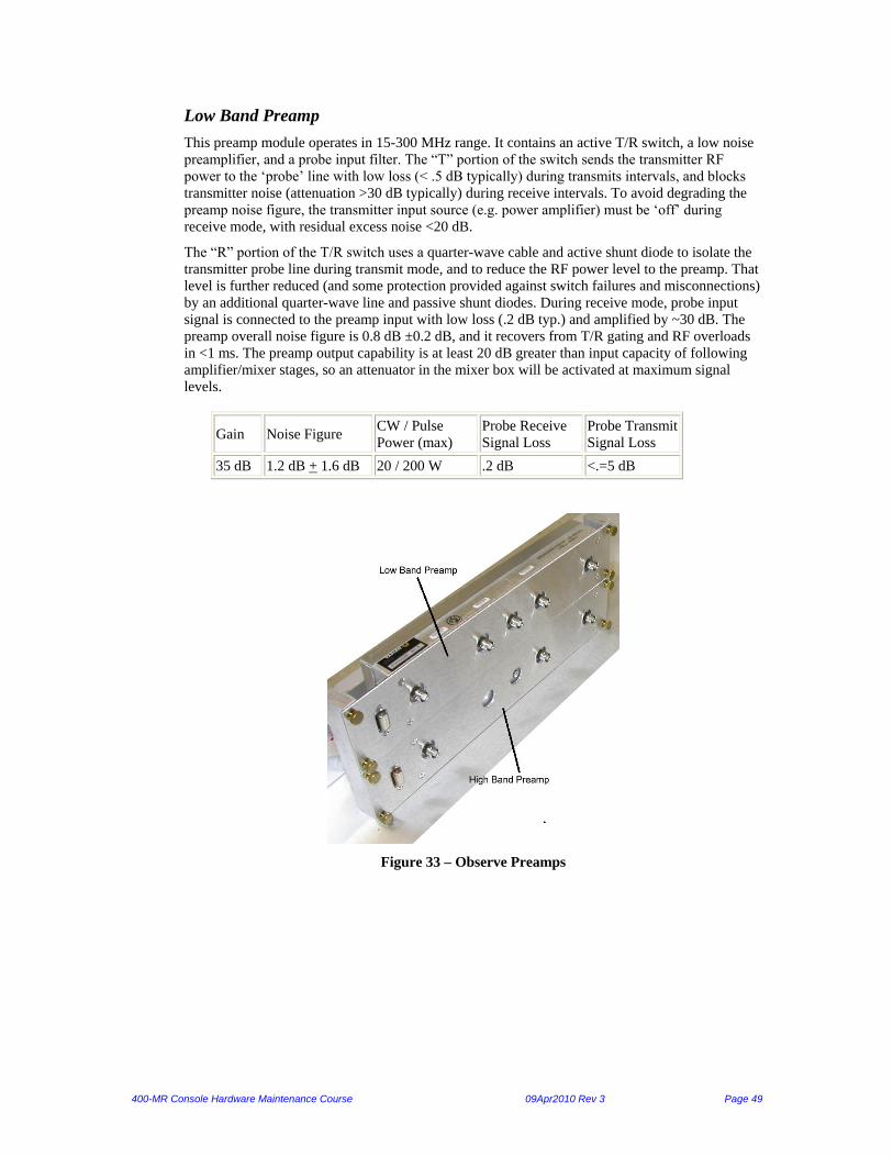
Low Band Preamp
This preamp module operates in 15-300 MHz range. It contains an active T/R switch, a low noise
preamplifier, and a probe input filter. The “T” portion of the switch sends the transmitter RF
power to the ‘probe’ line with low loss (< .5 dB typically) during transmits intervals, and blocks
transmitter noise (attenuation >30 dB typically) during receive intervals. To avoid degrading the
preamp noise figure, the transmitter input source (e.g. power amplifier) must be ‘off’ during
receive mode, with residual excess noise <20 dB.
The “R” portion of the T/R switch uses a quarter-wave cable and active shunt diode to isolate the
transmitter probe line during transmit mode, and to reduce the RF power level to the preamp. That
level is further reduced (and some protection provided against switch failures and misconnections)
by an additional quarter-wave line and passive shunt diodes. During receive mode, probe input
signal is connected to the preamp input with low loss (.2 dB typ.) and amplified by ~30 dB. The
preamp overall noise figure is 0.8 dB ±0.2 dB, and it recovers from T/R gating and RF overloads
in <1 ms. The preamp output capability is at least 20 dB greater than input capacity of following
amplifier/mixer stages, so an attenuator in the mixer box will be activated at maximum signal
levels.
Gain Noise Figure CW / Pulse
Power (max)
Probe Receive
Signal Loss
Probe Transmit
Signal Loss
35 dB 1.2 dB + 1.6 dB 20 / 200 W .2 dB <.=5 dB
Figure 33 – Observe Preamps

400-MR Console Hardware Maintenance Course 09Apr2010 Rev 3 Page 50
Figure 34 – Broad Band Preamp Schematic

400-MR Console Hardware Maintenance Course 09Apr2010 Rev 3 Page 51
Lock Preamp
This lock preamp is used on NMR systems from 200 to 750 MHz. It is wide band design, since the
noise image rejection is located on the receiver board.
In the receive mode, (LK Gate=low), U4 directs the incoming NMR signals at J5205 to Q2, a low
noise preamp input stage, followed by U5 and which are monolithic RF amps. The total gain is in
the 50 dB range. The lock transmitter frequency enters J5206 and passes through a 20 dB
switchable attenuator (U1 and U2). Q1 and U3 control the attenuator, which is usually in the dB
attenuation position. When the LK gate=high (J5204 = +5V), the lock transmitter signal is selected
by U4 and reaches the probe through J5205.
Figure 35 -- Lock Preamp

400-MR Console Hardware Maintenance Course 09Apr2010 Rev 3 Page 52
Figure 36 -- Lock Preamp Schematic

400-MR Console Hardware Maintenance Course 09Apr2010 Rev 3 Page 53
Lock Diplexer
The diplexer module uses passive components to provide decoupler noise isolation (by CR1-CR8)
and preamp protection (CR9-CR14). In the absence of decoupler RF power, the lock operates
normally; when RF power is applied to the “DECOUPLER” port it is delivered to the “PROBE”
port (W1 is ~1/4 wavelength), the “PREAMP” port is clamped, protecting the lock preamp. The
decoupler power amplifier must be in pulse mode, turned ”on” only during decoupling, to prevent
noise interference with lock signal reception.
Figure 37 – Lock Diplexer
Figure 38 -- Lock Diplexer Schematic

400-MR Console Hardware Maintenance Course 09Apr2010 Rev 3 Page 54
Tune Combiner
The Tune Combiner allows the system to tune on each channel on the probe without having to
move cables. It combines the outputs of the two directional couplers to the tune input of the mixer
module. It has 30db of isolation
between the two inputs and has an
insertion loss of about 0.3 to 0.6dB
with a frequency range of 5-
500MHz.
Figure 39 – Tune Combiner
Directional Couplers
The Directional Couplers allow the Transmit and Receive signals to pass to the probe coils while
allowing a connection to the probe coils for tuning. There are two directional couplers one for high
band and the other for low band.
Figure 40 – Directional Couplers
D.C. Frequency Coupling Insertion Loss Power Rating
High Band 400-900 MHz 30dB 0.25dB@650MHz 0.05 dB max 10 kW peak 750W Avg
Low Band 50-250 MHz 30dB 0.25dB@200MHz 0.05 dB max 10 kW peak 750W Avg
400-MR Console Hardware Maintenance Course 09Apr2010 Rev 3 Page 55
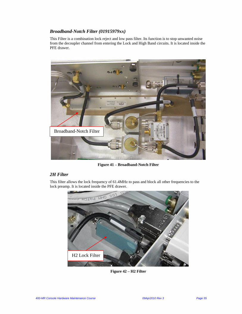
Broadband-Notch Filter (01915979xx)
This Filter is a combination lock reject and low pass filter. Its function is to stop unwanted noise
from the decoupler channel from entering the Lock and High Band circuits. It is located inside the
PFE drawer.
Figure 41 – Broadband-Notch Filter
2H Filter
This filter allows the lock frequency of 61.4MHz to pass and block all other frequencies to the
lock preamp. It is located inside the PFE drawer.
Figure 42 – H2 Filter
H2 Lock Filter
Broadband-Notch Filter

400-MR Console Hardware Maintenance Course 09Apr2010 Rev 3 Page 56
Gradient Relay
This relay is located attached to the outside of the preamps. The relay allows the observation of H2
on the lock coil of the probe using the second channel transmitter path.
Figure 43 -- Gradient Relay
Pneumatics
The Pneumatics has the following components inside of the drawer:
1. Flow Meter Board
2. Pressure Switch
3. Electro-Pneumatic Valves
Flow Meter Board
The Flow Meter provides an indication of how much gas flow there is going to the probe for
temperature control. A ball travels up and down the flow meter that blocks infrared emitting
diodes from reach the other side where the detectors are. This will turn off the LED.
LED = OFF, no threshold is set and the ball is between emitter and receiver.
LED = Green, no threshold is set and the ball is not between emitter and receiver.
LED = Yellow/Orange, threshold is set, but the ball is not between emitter and
LED = Red, threshold is set and the ball is between the emitter and receiver.

400-MR Console Hardware Maintenance Course 09Apr2010 Rev 3 Page 57
Figure 44 – Flow Meter

400-MR Console Hardware Maintenance Course 09Apr2010 Rev 3 Page 58
Figure 45 – Flow meter schematic

400-MR Console Hardware Maintenance Course 09Apr2010 Rev 3 Page 59
Pressure Switch, 20 PSI
The 20psi pressure switch is to provide feedback to the master controller to send out a pneumatic
fault to the VnmrJ software.
Figure 46 – 20psi pressure switch
Electro-Pneumatic Valves
There are four electro-pneumatic valves in the system to allow for VT gas regulation, ejection and
insertion of the sample, rotation of the sample, and to provide the bearing air to allow the sample
to spin.
Bearing Rotation Eject Temperature
Max Pressure 100 PSI 100 PSI 100 PSI 50 PSI
Figure 47 -- Electro-Pneumatic Valves
Temperature
Eject
Rotation Bearing

400-MR Console Hardware Maintenance Course 09Apr2010 Rev 3 Page 60
Pressure Regulators
The pressure regulators control the amount of gas flow into the upper barrel (bearing, rotation, and
eject), the accessory port. The temperature has two regulators, one for temperature and one for the
pre-temperature that feeds the temperature regulator. The temperature regulator has the 20psi
pressure switch attached to it.
Figure 48 – Regulators, top
Figure 49 – Regulators, bottom
Temperature Pre - Temp Accessory Upper Barrel

400-MR Console Hardware Maintenance Course 09Apr2010 Rev 3 Page 61
Chapter 5. DC/RF/Shim Power Module The DC/RF/Shim Power Module provides AC and various DC power outputs, houses up to two
RF power amplifiers and has a separate compartment to house a 28-channel shim driver board and
Z0/Z1 board for the 400-MR console.
AC/DC Power Module
This module converts AC to DC voltages used throughout the console. It has an auto-switching
input of 80 to 264 VAC single phase at 10A maximum on 47-63 Hz line frequency. There is one
breaker switch (CB1) located on the back of the rear panel that switches the power for the entire
unit. This is located in the bottom part of the DC/RF/Shim Power Module.
Figure 50 – Main Power Supply
There are two types of indicators that there is voltage. One green LED on the front of the unit for
master power. In addition, there are 7 green LED’s for DC power voltages: 5V, 3.3V, 7.5V, 11V,
15, 18V and +28V.

400-MR Console Hardware Maintenance Course 09Apr2010 Rev 3 Page 62
Figure 51 – DC Voltage Output
J 1 D C O u t p u t s
D C V o l t a g e M e a s u r e d
V o l t a g e
M a x
C u r r e n t C o m m e n t s
+15V 14.85V to 15.4V 1.2A To RF Boards
-15V -14.2V to –15.75V 1.0A To RF Boards
+7.5V 7.45V to 7.75V 3.5A To Digital Control Boards
+11V 11.1V to 11.5V 10.0A To RF Boards
-11V -11.1V to –11.5V 4.0A To RF Boards
J 2 D C O u t p u t s
D C V o l t a g e M e a s u r e d
V o l t a g e
M a x
C u r r e n t C o m m e n t s
+15V 14.85V to 15.4V 2.0A Spare, not used
-15V -14.2V to –15.75V 1.5A Spare, not used
+18V 18.0V to 18.5V 2.0A To PFE
-18V -18.0V to –18.5V 2.0A To PFE
+5V 5.35V to 5.42V 1.0A Spare, not used
+7.5V 7.45V to 7.75V 3.5A To PFE
J 3 D C O u t p u t s
D C V o l t a g e M e a s u r e d
V o l t a g e
M a x
C u r r e n t C o m m e n t s
+5V 5.35V to 5.42V 10.0A To Digital Control Boards
+3.3V 3.57V to 3.65V 10.0A To Digital Control Boards
J 4 D C O u t p u t s
D C V o l t a g e M e a s u r e d
V o l t a g e
M a x
C u r r e n t C o m m e n t s
+28V 28.1V to 28.9V 1.0A To PFE (for RF Relays)
FAN 15.0V to 21.0V 0.6A To cardcage Fans (voltage
is lower when connected).
Note:
Refer to the 400-MR Tech Support website for the latest updates regarding the power module DC
voltages. Refer to the document “400 DC voltages for the upgraded -12 version”
400-MR Console Hardware Maintenance Course 09Apr2010 Rev 3 Page 63
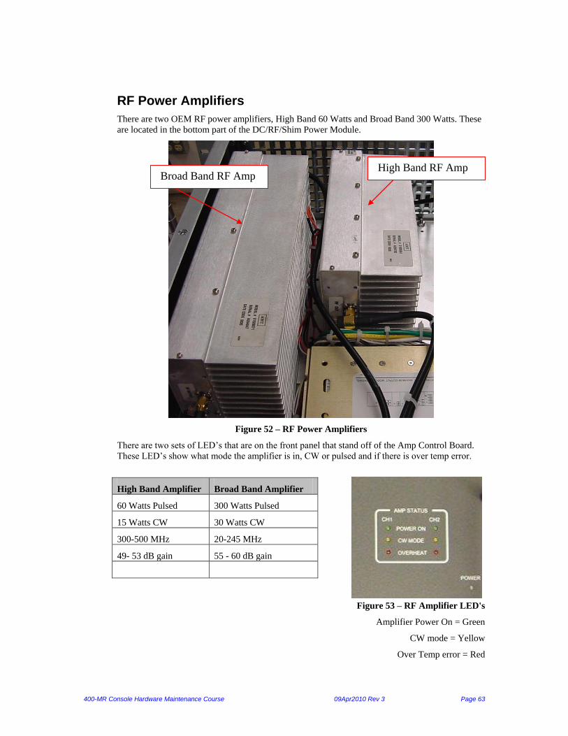
RF Power Amplifiers
There are two OEM RF power amplifiers, High Band 60 Watts and Broad Band 300 Watts. These
are located in the bottom part of the DC/RF/Shim Power Module.
Figure 52 – RF Power Amplifiers
There are two sets of LED’s that are on the front panel that stand off of the Amp Control Board.
These LED’s show what mode the amplifier is in, CW or pulsed and if there is over temp error.
High Band Amplifier Broad Band Amplifier
60 Watts Pulsed 300 Watts Pulsed
15 Watts CW 30 Watts CW
300-500 MHz 20-245 MHz
49- 53 dB gain 55 - 60 dB gain
Figure 53 – RF Amplifier LED's
Amplifier Power On = Green
CW mode = Yellow
Over Temp error = Red
High Band RF Amp Broad Band RF Amp

400-MR Console Hardware Maintenance Course 09Apr2010 Rev 3 Page 64
Amplifier Replacement:
If any RF amp fails in the -12 or earlier Power Module, the entire unit must be replaced. In
the -13 or later, the RF amps are replaceable. Refer to bulletin “MR-S-2010-07 - (2/24/2010)
Replaceable RF amplifiers” for details.
Amp Control/Status Board
This board routes the gate signals to the RF Amplifiers used in the Analytical NMR Systems. The
board also shows the status of the System Power Supply and the Amplifiers. This is located in the
bottom part of the DC/RF/Shim Power Module.
Figure 54 – Amp Control/Status Board
Note:
Refer to the Tech Support website for the latest service bulletins on the 400-MR power module
including bulletins:
1) “MR-S-2009-08 Power Module Upgrade”
2) “MR-S-2010-07 - (2/24/2010) Replaceable RF amplifiers”

400-MR Console Hardware Maintenance Course 09Apr2010 Rev 3 Page 65
28-Channel Shim Supply
The Shim Power Supply shall supply constant current for 28-shim coil in the magnet to correct the
homogeneity of the magnet field used in NMR applications. The unit consists of two PC boards:
The Main Driver Board and the Z0/Z1 II Board.
These boards are located in the top of the DC/RF/Shim Power Module.
Figure 55 – Shim Boards
Main Driver Board
The board detail can accommodate up to 26 current drivers for shim coils and two voltage drivers
for Z0/Z1 board. The current drive is as follows:
200mA for axial channels Z2, Z3, Z4
300mA for axial channels Z5, Z6, Z7
1 amp for transverse channels
The 200/300 mA drivers are intended for the axial shims; the 1-amp drivers are intended for the
transverse shims. All channels have 16-bit DAC resolution. The board consists of the voltage-to-
current drivers plus an optically isolated serial digital interface that controls the analog multiplexer
channel selection and the DAC setting.

400-MR Console Hardware Maintenance Course 09Apr2010 Rev 3 Page 66
Figure 56 – Main Shim Driver Board
Shim Z0/Z1 II Board
This board consists of two essentially independent circuits for the Z0 and Z1 shim coils. They
each have independent supplies and grounding; they share only a common optically isolated input
signal interface. The Z0 section contains a voltage-to-current driver similar to the other driver
channels in the shim box system. In addition, it contains the lock loop filter circuitry. The lock
loop filter has an integrator to compensate for high drift magnets and it has a hold mode required
for certain experiments that require the lock signal to remain constant for a short period of time.
The Z1 section contains a similar voltage-to-current converter except that it has a higher
bandwidth. This makes it possible to generate fast homospoil pulses to disturb the magnet field.
The Lock Polarity switch SW1 is accessible via a removable side plate.
Homospoil adjustment is accessible via a small hole in the front panel.
The current drive is as follows:
22mA for axial channels Z0
100mA for axial channels Z1
0.5 amps for 200ms Homospoil pulse

400-MR Console Hardware Maintenance Course 09Apr2010 Rev 3 Page 67
Figure 57 -- Z0/Z1 Shim Board
Chapter 6. Temperature & PFG
Highland L300
The L300 is the combination Pulsed Field Gradient Amplifier and Temperature Controller from
Highland.
The Pulsed Field Gradient (PFG) amplifier is a high-precision pulsed constant-current power
source intended to drive gradient magnetic field coils in NMR systems. The unit accepts digital
data inputs, and provides a single analog output.
The Temperature Controller is a closed-loop temperature controller for NMR sample temperature
stabilization, via chilled/reheated gas loop.
Figure 58 – L300 PFG & VT
The L300 specifications are as follows:
General:
Universal power: auto-ranging 85-132 / 180-264 volts 47-63 Hz switcher supply.
PFG amplifier:
3 Amp output
Temperature Controller:
100 W output for liquids heater (20 Ohm)
-150 C to +250 C (gas flow range 5 to 25 LPM)
±0.2 C accuracy with constant carrier gas flow

400-MR Console Hardware Maintenance Course 09Apr2010 Rev 3 Page 68
±0.2 C stability after warm-up and over 24 hours
PFG Front Panel LED Indicators:
PFG State - "ENABLED" (green) – indicates that PFG unit is in operating mode
PFG Data - "DATA" (yellow) – flashes when the current data value is loaded
PFG Error - "ERROR" (red) – ‘on’ indicates that the internal control system has detected
an error; possible errors include excessive time/current pulse request, AC line voltage error,
internal fuse or component error.
PFG Load - "LOAD" (red) – ‘on’ indicates the load is open or the load has too high a
resistance for normal operation.
PFG Switch - "ON STANDBY" –
black 2-position switch – used for
distinguishing between standby and
enabled.
Figure 59 – PFG LED’s
Temperature Controller LED Indicators:
VT State - "STATE" (yellow) - Blinking when in MANUAL or AUTO with temperature
not settled and - Steady when in AUTO with temperature settled.
VT Error - "ERROR" (red) – 'on' indicates that the internal control system has detected an
error; possible errors include excessive temperature request, AC line voltage error, internal
fuse or component error.
Figure 60 – VT LEDs

400-MR Console Hardware Maintenance Course 09Apr2010 Rev 3 Page 69
Chapter 7. Troubleshooting
Software Troubleshooting Tools
Purpose Section A teaches you how to use software diagnostic tools to check the console via
messages sent by a controller or VnmrJ itself.
Section B teaches you how to use rlogin and how to initialize a controller
SECTION A:
Forgotten Root Password in Linux
The following steps reset the root password in linux:
a. Reboot the Dell computer
b. Press any key when the GRUB menu is displaied to stop the boot process
c. At the kernel line, Press the “a” key to append it
d. At the end of the kernel line, add –s and then enter
e. Once, the system boots up into signal user mode, type passwd root
f. Then enter a new password for root.
g. Type exit
To spy on the controllers use acqdebug(11) : See example #1 in examples section:
1) To save the data to a file, type script filename (choose a name) in a terminal window. Then
rlogin to the controller from that window (this is to be repeated for any and all
controllers)
2) If you are monitoring several controllers at the same time, create a directory in a
convenient place. Start the script file for each controller from within that directory, and all
the scripts will be in an easy-to-tar location.
3) Type acqdebug(11) in the Vnmr command line. This will start debug for all controllers that
have been logged into. Alternatively, you can type DebugLevel=1 in the controllers’ window
at the arrow prompt. You will have to do this for each controller.
4) To end the session, type exit at the controller’s arrow prompt, and then cntl-D to end the
script file. You will have to do this for each controller you are logged into.
To spy on proc family use acqdebug(01): See example #2 in examples section:
In terminal window type the following:
1) su acqproc (to kill)
2) script filename (to start a script file called filename)
3) su acqproc (to start)
4) On the command line type: acqdebug(01)

400-MR Console Hardware Maintenance Course 09Apr2010 Rev 3 Page 70
5) When you are done, save script filename with control-D
To see commands and/or macros being executed in VnmrJ: See example #3 in examples section:
1) In a terminal window type: tty (note the output number)
2) On the VJ command line type:
a) jFunc(55, ‘/dev/pts/#’) [ /dev/pts/## is found in step #1]
b) debug(‘c’) [lower case ‘c’ turns on tracing; upper case ‘C’ turns it off]
3) Run experiments/commands
- messages are echoed in the terminal window
- commands or macros that execute properly will show “started” and “returned”
- look for macros or commands that are “aborted”
4) This is also very, very chatty. You can save this output to a file as well. On the command
line, type: jFunc(55,’filename’)
It will write this file where ever you happen to be, so before typing the command, type pwd in the
Vnmr command line to make certain you are in a reasonable (and writeable) spot. Typing cd in
the command line before starting is always safe
EXAMPLES SECTION: 1) Spy on the controllers output: [vnmr1@pt21 ~]$ script controller
Script started, file is controller
[vnmr1@pt21 ~]$ minicom -o
Welcome to minicom 2.00.0
OPTIONS: History Buffer, F-key Macros, Search History Buffer, I18n
Compiled on Jun 15 2004, 21:09:30.
Press CTRL-A Z for help on special keys
-> 00:03:09 'nexus.c' line: 369, CntlrPlexus(): SET_DEBUGLEVEL: DebugLevel = 1
00:03:27 'NDDS_SubFuncs.c' line: 56, A new publication took over my Subscripti.00:03:27
'NDDS_SubFuncs.c' line: 365, PubId: 259 (0x103), topic: 'h/rf3/dwnld/'00:03:27
'NDDS_SubFuncs.c' line: 366, Time Sent: 1181085560.352110999, Time Re800:03:27
'NDDS_SubFuncs.c' line: 368, Pub Seq#: 0, 1619, Recv'd Seq#: 0, 1
00:03:27 'NDDS_SubFuncs.c' line: 369, senderAppId: 0x801801, senderHostId: 0xa100:03:27
'NDDS_SubFuncs.c' line: 370, status: 'A new issue received'
00:03:27 'downLink.c' line: 179, -------- C_DNWLD_START Received, give Semap800:03:27
'NDDS_SubFuncs.c' line: 365, PubId: 259 (0x103), topic: 'h/rf3/dwnld/'00:03:27
'NDDS_SubFuncs.c' line: 366, Time Sent: 1181085560.352170999, Time Re800:03:27
'NDDS_SubFuncs.c' line: 368, Pub Seq#: 0, 1620, Recv'd Seq#: 0, 2
00:03:27 'NDDS_SubFuncs.c' line: 369, senderAppId: 0x801801, senderHostId: 0xa100:03:27
'NDDS_SubFuncs.c' line: 370, status: 'A new issue received'
00:03:27 'downLink.c' line: 276, Receiving: 'exp7lc0', total size: 396, size s000:03:27
'downLink.c' line: 247, Recv'd: Acodes: 0, Patterns: 0, Tables: 0
00:03:27 'nexus.c' line: 362, CntlrPlexus(): ROLLCALL
00:03:27 'NDDS_SubFuncs.c' line: 365, PubId: 259 (0x103), topic: 'h/rf3/dwnld/'00:03:27
'NDDS_SubFuncs.c' line: 366, Time Sent: 1181085560.364804999, Time Re000:03:27
'NDDS_SubFuncs.c' line: 368, Pub Seq#: 0, 1621, Recv'd Seq#: 0, 3
00:03:27 'NDDS_SubFuncs.c' line: 369, senderAppId: 0x801801, senderHostId: 0xa100:03:27
'NDDS_SubFuncs.c' line: 370, status: 'A new issue received'
00:03:27 'downLink.c' line: 276, Receiving: 'exp7f0', total size: 176, size se000:03:27
'downLink.c' line: 247, Recv'd: Acodes: 1, Patterns: 0, Tables: 0
400-MR Console Hardware Maintenance Course 09Apr2010 Rev 3 Page 71
00:03:27 'NDDS_SubFuncs.c' line: 365, PubId: 259 (0x103), topic: 'h/rf3/dwnld/'00:03:27
'NDDS_SubFuncs.c' line: 366, Time Sent: 1181085560.377510999, Time Re300:03:27
'NDDS_SubFuncs.c' line: 368, Pub Seq#: 0, 1622, Recv'd Seq#: 0, 4
00:03:27 'NDDS_SubFuncs.c' line: 369, senderAppId: 0x801801, senderHostId: 0xa100:03:27
'NDDS_SubFuncs.c' line: 370, status: 'A new issue received'
00:03:27 'downLink.c' line: 202, ---------- C_DNWLD_CMPLT Recieved, give Semae00:03:28
'nexus.c' line: 387, CntlrPlexus(): APARSER: cmd: 5, Acodes: 1, Table'00:03:29
'AParser.c' line: 318, APstart()- ExpName: 'exp7' Num Acodes: 1 Num000:03:29
'AParser.c' line: 328, APstart(): Waiting for at least 1 codes to be d00:03:29
'downLink.c' line: 492, nDownldCodes: 1, nDownldTables: 0, nDownldPat000:03:29
'AParser.c' line: 549, getAcodeSet: Find acode buffer: exp7f0
00:03:29 'A32Interp.c' line: 1235, A32Interp(): pAcodeId->cur_acode_size: 152 s00:03:29
'A32Interp.c' line: 1391, WAIT4ISYNC, postdelay ticks: 320
00:03:29 'shandler.c' line: 381, addPendingSWItr: add Acode 0xacd00004 to pendt00:03:29
'A32BridgeFuncs.c' line: 897, SETVT: type=2 pid=440 temp=30000 tmpoff000:03:29
'shandler.c' line: 381, addPendingSWItr: add Acode 0xacd00004 to pendt00:03:29
'A32Interp.c' line: 2862, RFINFO band=0, xmtr=0, power=-1
00:03:29 'A32Interp.c' line: 2231, END_PARSE 1
00:03:29 'shandler.c' line: 381, addPendingSWItr: add Acode 0x11 to pending lit00:03:29
'cntrlFifoBufObj.c' line: 761, fifoBufForce(): Send Buf: *0x3c87ba0=0100:03:29
'A32BridgeFuncs.c' line: 275, startCntrlFifo(): fifoStarted4Exp: 'NO'00:03:29
'A32BridgeFuncs.c' line: 290, Cntlr used cntrlFifoStartAndSync()
interrupt: =========== Cntrl FIFO - Started Duration: 0 | 1f8
interrupt: ========= Levels Instr: 0, Data: 20
interrupt: =========== Cntrl FIFO - Stopped Duration: 0 | 280
00:03:29 'shandler.c' line: 271, sHandler(): SW Itr 4, signal
00:03:29 'shandler.c' line: 367, Tell Master I'm Ready4sync
00:03:29 'nameClBufs.c' line: 731, nClbFreeByName: 'exp7f0'
00:03:29 'nameClBufs.c' line: 945, nClbFreeByRootName: delete: 'exp7lc0'
00:03:29 'downLink.c' line: 913, number deleted: 1
interrupt: =========== Cntrl FIFO - Started Duration: 0 | 2d8
interrupt: ========= Levels Instr: 0, Data: 16
interrupt: =========== Cntrl FIFO - Stopped Duration: 0 | 3c0
00:03:29 'shandler.c' line: 271, sHandler(): SW Itr 4, signal
00:03:29 'shandler.c' line: 367, Tell Master I'm Ready4sync
interrupt: =========== Cntrl FIFO - Started Duration: 0 | 280
interrupt: ========= Levels Instr: 0, Data: 14
interrupt: =========== Cntrl FIFO - Stopped Duration: 0 | 7a15ec
00:03:30 'shandler.c' line: 257, sHandler(): SW Itr 1, signal
00:03:30 'shandler.c' line: 533, SETUP_CMPLT
00:03:30 'shandler.c' line: 538, >> Fifo Instructions Sent: 41, --> Recv'd: 41000:03:30
'shandler.c' line: 638, Sent Master Setup Completed State
->
2) Spy on the procs output: Script started on Tue 05 Jun 2007 04:32:47 PM PDT
[vnmr1@pt21 ~]$ su acqproc Starting Acquisition communications.
[vnmr1@pt21 ~]$ Expproc states:
Authorization Records:
Record: 0, Count: 0, Level: Acquire, User: '', Host: '', PID: 0
This Process ID is Non-Active
Record: 1, Count: 0, Level: Acquire, User: '', Host: '', PID: 0
This Process ID is Non-Active
16:33:13: 'expQfuncs.c' line: 699,
Exp Queue, Priority: 0, In Queue: 0, 1st Entry Addr: 0xf72f1004
16:33:13: 'expQfuncs.c' line: 699,
Exp Queue, Priority: 1, In Queue: 0, 1st Entry Addr: 0xf72f7408
16:33:13: 'expQfuncs.c' line: 1016,
Active Queue: In Queue: 0, 1st Entry Addr: 0xf72fe004
16:33:13: 'recvfuncs.c' line: 1645, debugLevel: New DebugLevel: 1
16:33:13: 'procfuncs.c' line: 448, debugLevel: New DebugLevel: 1
16:33:13: 'sendproc.c' line: 283, processMsge(): received -1 bytes, No Message
16:33:13: 'process.c' line: 80, Procproc: start procQtask()(chk processing Q)
16:33:33: 'expproc.c' line: 246, Expproc: Received SIGIO, processIO()
16:33:33: 'expsocket.c' line: 197, Accepted Sockets in Queue: 1
400-MR Console Hardware Maintenance Course 09Apr2010 Rev 3 Page 72
16:33:33: 'expsocket.c' line: 277, processAcceptSocket: size: 55, msge: 'add2Qtail
/vnmr/acqqueue/exp7.vnmr1.074427, 7 vnmr1 1,'
16:33:33: 'msgehandler.c' line: 694, add2QTail: filename:
'/vnmr/acqqueue/exp7.vnmr1.074427', info: ' 7 vnmr1 1'
16:33:33: 'msgehandler.c' line: 402, ChkQ.
16:33:33: 'expQfuncs.c' line: 699,
Exp Queue, Priority: 0, In Queue: 0, 1st Entry Addr: 0xf72f1004
16:33:33: 'expQfuncs.c' line: 699,
Exp Queue, Priority: 1, In Queue: 1, 1st Entry Addr: 0xf72f7408
16:33:33: 'expQfuncs.c' line: 705, (1): ExpId: '/vnmr/acqqueue/exp7.vnmr1.074427'
16:33:33: 'expQfuncs.c' line: 706, (1): ExpInfo: ' 7 vnmr1 1'
16:33:33: 'msgehandler.c' line: 424, chkExpQ: 0 Processing Q entries
16:33:33: 'msgehandler.c' line: 425, chkExpQ: 0 Active Processing Q entries
16:33:33: 'semLib.c' line: 433, semOpen: SEMID: 196614
16:33:33: 'ipcMsgQLib.c' line: 126, msgQCreate: created msgId = 32769
16:33:33: 'semLib.c' line: 433, semOpen: SEMID: 196614
16:33:33: 'ipcMsgQLib.c' line: 126, msgQCreate: created msgId = 98307
16:33:33: 'msgehandler.c' line: 458, Send Recvproc: 'recv
/vnmr/acqqueue/exp7.vnmr1.074427'
16:33:33: 'msgehandler.c' line: 464, Send Sendproc: 'send
/vnmr/acqqueue/exp7.vnmr1.074427 exp7'
16:33:33: 'msgehandler.c' line: 481, chkExpQ: # Acodes: 1, # FIDs: 1, Jpsg flag: 0,
startAcode: 0
16:33:33: 'recvproc.c' line: 253, Recvproc: Received SIGUSR1, processMsge()
16:33:33: 'msgehandler.c' line: 483, chkExpQ: ActiveExpInfo.ExpInfo->PSGident = 1 (100-
JPSG, 1-C PSG)
16:33:33: 'recvproc.c' line: 325, received 37 bytes, MsgInbuf len 37 bytes, Msge: 'recv
/vnmr/acqqueue/exp7.vnmr1.074427'
16:33:33: 'recvfuncs.c' line: 264,
|||||||||||||||||||||||||||||||||||||||||||||||||||
>>>>>>>>> recvData Invoked.
16:33:33: 'semLib.c' line: 433, semOpen: SEMID: 196614
16:33:33: 'ipcMsgQLib.c' line: 126, msgQCreate: created msgId = 196610
16:33:33: 'semLib.c' line: 433, semOpen: SEMID: 196614
16:33:33: 'ipcMsgQLib.c' line: 126, msgQCreate: created msgId = 163840
16:33:33: 'recvfuncs.c' line: 293,
--------------------
----- Preparing for: '/vnmr/acqqueue/exp7.vnmr1.074427' data.
3) jFunc output when executing “su” command: [vnmr1@pt21 ~]$ tty
/dev/pts/1
[vnmr1@pt21 ~]$ terminal /dev/pts/1 opened.
command vnmrjcmd started
command vnmrjcmd returned
macro ga started
macro isspincad started
command exists started
command exists returned
command exists started
command exists returned
command exists started
command exists returned
command exists started
command exists returned
macro isspincad returned
command exists started
command exists returned
macro setdsp started
command exists started
command exists returned
command on started
command on returned
macro setdsp returned
command on started
command on returned

400-MR Console Hardware Maintenance Course 09Apr2010 Rev 3 Page 73
command exists started
command exists returned
command exists started
command exists returned
command exists started
command exists returned
command exists started
command exists returned
command exists started
command exists returned
macro reqpartest started
command exists started
command exists returned
command exists started
command exists returned
command length started
command length returned
command substr started
command substr returned
macro gettoken started
command length started
command length returned
command length started
command length returned
command strstr started
command strstr returned
macro gettoken returned
command length started
command length returned
command substr started
command substr returned
macro gettoken started
command length started
command length returned
command length started
command length returned
command strstr started
command strstr returned
macro gettoken returned
command length started
command length returned
command substr started
command substr returned
macro gettoken started
command length started
command length returned
command length started
command length returned
command strstr started
command strstr returned
macro gettoken returned
macro reqpartest returned
command exists started
command exists returned
command on started
command on returned
command exec started
command Acq started
command Acq returned
command exec returned
command exists started
command exists returned
macro ga returned

400-MR Console Hardware Maintenance Course 09Apr2010 Rev 3 Page 74
SECTION B
rlogin
rlogin is a method to log into the controllers
To check the flash memory files open terminal window and type:
rlogin controller-name
ffdir (should list all 10 files in flash)
To check rollcall or sync readiness on controllers type in a terminal window:
rlogin master1
DebugLevel=1
rollcall
minicom
Minicom is a serial communication program that allows a user to view the bootup messages and
re-initialize a controller, much like that of “tip hardware” command used in Solaris.
To set up minicom do the following:
1. In a terminal as root type:
a. minicom -s (setup option to edit the defaults in /etc/minirc.dfl)
i. hit enter (ignore any warning message)
ii. hit enter (a window pops out)
iii. hit enter (new window appears)
b. Scroll to “serial port setup” & hit enter
c. In the new window:
i. Select “A” to change the serial device to /dev/ttyS0 then hit enter
ii. Select “E” to change the “comm parameters”
iii. In the new window:
1. Select “I” to set speed to 115200
2. Select “L” to set parity to none
3. Top line should now read “current: 115200 8N1”
4. If not then also
a. Select “V” sto set data bits to 8
b. Select “W” to set stop bits to 1
5. Hit enter to exit this window
6. Select “F” to toggle hardware flow control to NO
7. Hit enter to exit
iv. Scroll to “modem & dialing” then hit enter
v. In the new window
1. Select “A” & delete all characters to the left but not the dots
(periods) and then hit enter

400-MR Console Hardware Maintenance Course 09Apr2010 Rev 3 Page 75
2. Hit enter to exit this window
d. Scroll to “save setup as dfl” and hit enter
i. Scroll to “exit from minicom” and hit enter 2x to get the root prompt
e. At the root prompt type in:
i. chmod 666 /dev/ttyS0 (so that any user can run minicom by accessing the
serial port)
2. Attach a NULL-modem cable from the controller’s 9-pin diagnostic port to the host computer
serial port.
3. In a terminal and as any user type:
a. minicom –o and then hit enter, this will bring up the welecome screen with a
blinking cursor.
4. Press the “control” and “X” keys together or the reset button on the controller to view the
bootup messages. You can also preempt the bootup by hitting the space bar to re-initialize the
controller.
Controller Initialization Procedure
NOTE:
For the latest updates on this procedure, refer to the “Controller Initialization” document on the
Tech Support web site.
This procedure describes how to manually load the necessary files and scripts into each of the
digital controllers. For each controller, do the following:
1. Run minicom –o
2. Attach cable from controller diag port to host serial port
3. Reset board & hit space bar within 4 sec (note that LEDS ds1-5 will all light up)
You should see the header file:
Varian visionWARE v2.1 PPC405GPR Controller Board
Build #31, 10/04/04 09:06:55
MAC : 00-60-93-03-10-04 IP : 172.16.0.5
Type "shell" to set IP and/or MAC addresses
Type "help" to see available commands
4. At the prompt (BCP>) type dir
You should see one of the following:
If flash is empty you will see:
0 file(s) 0 bytes 15,597,568 bytes free
If flash has files you should see 9 files that were downloaded + boot.ini
Similar to the following table:
boot.ini 1384 bytes
vxWorks405gpr.bdx 2468224 bytes
pfgexec.o 289793 bytes

400-MR Console Hardware Maintenance Course 09Apr2010 Rev 3 Page 76
nvlib.o 304857 bytes
rfexec.o 289845 bytes
masterexec.o 698661 bytes
nvScript 891 bytes
lockexec.o 179622 bytes
gradientexec.o 364295 bytes
ddrexec.o 571147 bytes
10 file(s) 5168719 bytes
10428849 bytes free
Note:
11 files may be present depending on the software version. With VJ 2.3A or later, 11 files
will be present. A new file called nddslib.o is present and very large in size.
5. Type shell
This allows the change of the board IP and wormhole IP in the boot PROM, which is
important only when initializing a controller using the copy command. For each line
hit enter if correct or type in the correct info followed by the enter key.
a. If a controller is blank, you should see this:
Command Channel = 0: serial >
Boot Delay (seconds) = 0 >
Boot Script = >
Prompt String = BCP >
MAC Address = 00-60-93-03-10-04 >
IP Address = 172.16.0.5 >
Subnet Mask = 255.255.0.0 >
Default Gateway = 0.0.0.0 >
Remote System 1 Name = wormhole >
Remote System 1 IP = 172.16.0.1 >
Remote System 2 Name = >
Remote System 3 Name = >
Remote System 4 Name = >
b. If a controller is NOT blank, you should see this (this is for RF1):
Command Channel = 0: serial >
Boot Delay (seconds) = 4 >
Boot Script = load vxWorks405gpr.bdx ! launch 10000 >
Prompt String = BCP >
MAC Address = 00-60-93-03-10-04 >
IP Address = 172.16.0.20 >
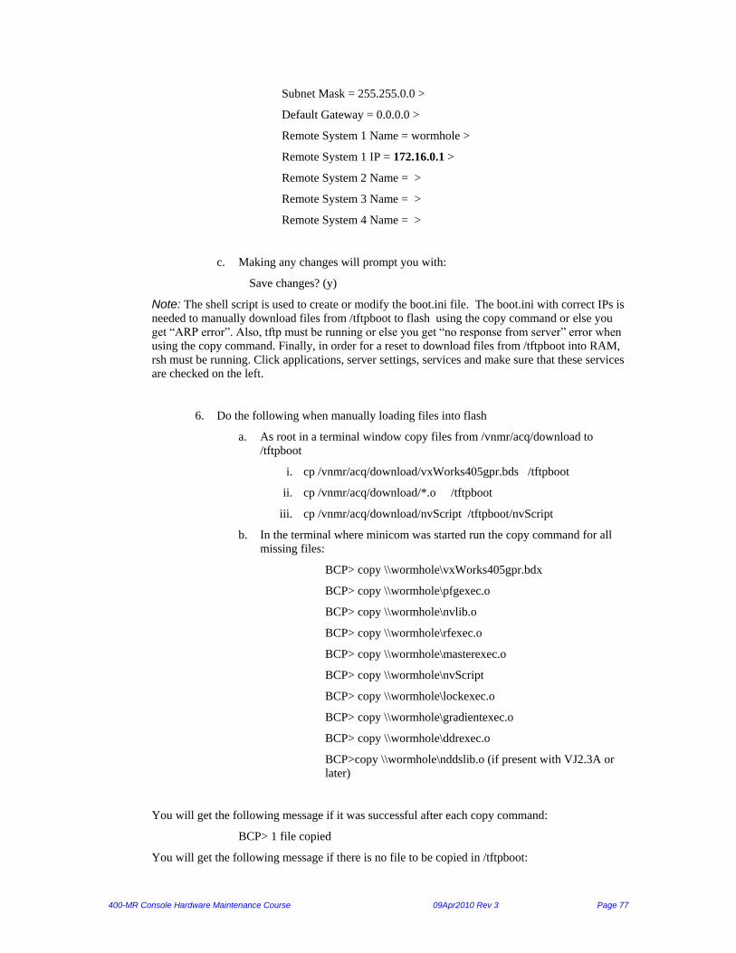
400-MR Console Hardware Maintenance Course 09Apr2010 Rev 3 Page 77
Subnet Mask = 255.255.0.0 >
Default Gateway = 0.0.0.0 >
Remote System 1 Name = wormhole >
Remote System 1 IP = 172.16.0.1 >
Remote System 2 Name = >
Remote System 3 Name = >
Remote System 4 Name = >
c. Making any changes will prompt you with:
Save changes? (y)
Note: The shell script is used to create or modify the boot.ini file. The boot.ini with correct IPs is
needed to manually download files from /tftpboot to flash using the copy command or else you
get “ARP error”. Also, tftp must be running or else you get “no response from server” error when
using the copy command. Finally, in order for a reset to download files from /tftpboot into RAM,
rsh must be running. Click applications, server settings, services and make sure that these services
are checked on the left.
6. Do the following when manually loading files into flash
a. As root in a terminal window copy files from /vnmr/acq/download to
/tftpboot
i. cp /vnmr/acq/download/vxWorks405gpr.bds /tftpboot
ii. cp /vnmr/acq/download/*.o /tftpboot
iii. cp /vnmr/acq/download/nvScript /tftpboot/nvScript
b. In the terminal where minicom was started run the copy command for all
missing files:
BCP> copy \\wormhole\vxWorks405gpr.bdx
BCP> copy \\wormhole\pfgexec.o
BCP> copy \\wormhole\nvlib.o
BCP> copy \\wormhole\rfexec.o
BCP> copy \\wormhole\masterexec.o
BCP> copy \\wormhole\nvScript
BCP> copy \\wormhole\lockexec.o
BCP> copy \\wormhole\gradientexec.o
BCP> copy \\wormhole\ddrexec.o
BCP>copy \\wormhole\nddslib.o (if present with VJ2.3A or
later)
You will get the following message if it was successful after each copy command:
BCP> 1 file copied
You will get the following message if there is no file to be copied in /tftpboot:

400-MR Console Hardware Maintenance Course 09Apr2010 Rev 3 Page 78
BCP>copy \\wormhole\nvScript error 1209A4: no response from server
7. Reset the controller you are connected via the diagnostic port
8. Run setacq. You should see all controllers DS5 flash for each checked file (no
download occurs since you manually installed all files in flash)
Notes:
If a controller could not be initialized using the “Controller Initialization” procedure,
remove the Ethernet cable from this controller so setacq will not hang and can download
to the rest of the controllers.
It is important to have IP and 'wormhole' set right in the shell command when the
controller board has no files in flash. When using this mode, the controller card is not
booted to vxWorks. At the BCP> prompt the board bootup has been interrupted by hitting
the space bar.
During the boot cycle, the controller requests its IP address and host name via the net
(RARP). Then it boots vxWorks, followed by nvlib.o and 'flavor'exec.o. At this point you
can ping it and rlogin to it, no matter what the 'shell' says. Once you can boot, you can
also use setacq to load the latest files into flash and you can forget the "copy
\\wormhole...." commands.

400-MR Console Hardware Maintenance Course 09Apr2010 Rev 3 Page 79
Bootup messages for master1 on VJ 2.3A: Welcome to minicom 2.00.0
OPTIONS: History Buffer, F-key Macros, Search History Buffer, I18n
Compiled on Jun 15 2004, 21:09:30.
Press CTRL-A Z for help on special keys
GPIO IR: 0x21040000
GEO: Type 0, (0x0), Address: 0, (0x0)
Varian visionWARE v2.1 PPC405GPR Controller Board
Build #32, 01/20/05 16:10:00
MAC : 00-60-93-03-00-01 IP : 10.190.50.171
Type "shell" to set IP and/or MAC addresses
Type "help" to see available commands
Press a key in the next <4> seconds to preempt boot script
Booting from script...
load vxWorks405gpr.bdx !launch 10000
CPC0_CR0: 0x383a
CPC0_CR0: 0x83a
CPC0_CR0: 0x383a
OsParams Address: 0x3e57964
Signature: 'vWARE', Version: 2
pVwareEntry: 0x3e22710, Func Table Addr: 0x3e032c8
sysLanIbmEmacEnetAddrGet: Vware started
Attached TCP/IP interface to emac unit 0
Attaching network interface lo0... done.
sysResolveIpAddr(); MAC: 00:60:93:03:00:01:
sysResolveIpAddr(); RARP request sent, waiting for reply
++++++++++++++++++++++++ rarpInputHook +++++++++++++++++++++++++++++
packet length: 110
EtherHeader Source MAC: 00:12:3f:6f:04:0b
EtherHeader Destination MAC: 00:60:93:03:00:01
EtherHeader type: 0x800 (0x8035-rarp, 0x806-arp, 0x800-ip
Not REVARP.
++++++++++++++++++++++++ +++++++++++++++++++++++++++++
++++++++++++++++++++++++ rarpInputHook +++++++++++++++++++++++++++++
packet length: 60
EtherHeader Source MAC: 00:12:3f:6f:04:0b
EtherHeader Destination MAC: 00:60:93:03:00:01
EtherHeader type: 0x8035 (0x8035-rarp, 0x806-arp, 0x800-ip
ARP Type: 4 (ARP_REQUEST=1, ARP_REPLY=2 RARP_REQUEST=3 RARP_REPLY=4)

400-MR Console Hardware Maintenance Course 09Apr2010 Rev 3 Page 80
Src MAC: 00:12:3f:6f:04:0b
Src IP: 172.16.0.1
Target MAC: 00:60:93:03:00:01
target IP: 172.16.0.10
Target MAC: 00:60:93:03:00:01
Local MAC: 00:60:93:03:00:01
resolved IP: 172.16.0.10
++++++++++++++++++++++++ +++++++++++++++++++++++++++++
sysResolveIpAddr(); MAC: 00:60:93:03:00:01:
sysResolveIpAddr(); RARP request sent, waiting for reply
sysResolveIpAddr(); MAC: 00:60:93:03:00:01:
sysResolveIpAddr(); RARP request sent, waiting for reply
sysResolveIpAddr(); RARP Reply IP: '172.16.0.10'
Target: 'master1', IP: '172.16.0.10'
Host: 'wormhole', IP: '172.16.0.1'
Skip DHCP Request.
Adding 4317 symbols for standalone.
CPU: IBM PowerPC 405GPr Varian
Controller. Proc. Memory Size: 0x2000000.
BSP version 1.2/7.
WDB Comm Type: WDB_COMM_END
WDB: Ready.
FFS file 'nvScript' opened, 1025 bytes
Executing FFS startup script 'nvScript' ...
#
nvld "/tftpboot/nddslib.o"
FFS file 'nddslib.o' opened, 5844541 bytes
value = 20552520 = 0x1399b48
nvld "/tftpboot/nvlib.o"
FFS file 'nvlib.o' opened, 754122 bytes
value = 25642904 = 0x1874798
nvrdate("wormhole")
value = 0 = 0x0
date
WED JUL 29 18:28:47 2009
value = 25 = 0x19
#
# systemInit(NetworkDisk_BasePath, BringUp_Level, DebugLevel,
ConsoleType, Flag)#
# NetworkDisk_BasePath - if NULL then the bit and exec files are loaded
from flh# Otherwise used as the directory on the
network drive to .# e.g. NetworkDisk_BasePath = /tftpboot
/tftpboot/xxxexec.o are loaded
#
# systemInit("/tftpboot",0,1,0,0) load bit and exec.o from
/tftpboot
#
# BringUp_Level - level of software service, etc. started
# 0 = only dma drivers initialized.
# 1 = DMA, NDDS, initialized
# Bringup is called.
# 2-9 Reserved for future use.
#
# DebugLevel - Level of Diagnostic Output, 0 = None, 1 - minimum,

400-MR Console Hardware Maintenance Course 09Apr2010 Rev 3 Page 81
# 2 - NDDS output, 3-10 more
output
#
# ConsoleType - Type of console , used to load proper varient of FPGA
# 0 = VNMRS (a.k.a. Nirvana)
#
# Flags - reserved for special purposes
# 0 = default
#
systemInit(0,1,-2,0,0)
emac0 previous queue length was 50
Queue length set at: 200
IP input maximum queue length = 50
Arp input maximum queue length = 50
New IP input maximum queue length = 200
New Arp input maximum queue length = 50
GPIO IR: 0x23043e00
GEO: Type 0, (0x0), Address: 0, (0x0)
------- systemInit createDomain
hostname : 'master1'
IP val: 0xac10000a
Local IP: '172.16.0.10'
File: '(null)/master_top.bit' not found on FFS.
18:28:47++++++ Loading Exec file: 'masterexec.o'
FFS file 'masterexec.o' opened, 975994 bytes
Sending configuration data to FPGA
FPGA Configuration Successful.
Reseting FPGA via GPIO line.
18:28:49 FPGA ID: 0, Rev: 0, Chksum: 16361; master.c Chksum: 16361,
Compiled:918:28:49 FPGA ID: 0, Rev: 0, Chksum: 16361; master.c
Chksum: 16361, Compiled:9reg ptr: 0x157b014, Int mask: 0x130f, instr
fifo size: 1024
18:28:49 'cntrlFifoBufObj.c' line: 98, fifoBufCreate(): Creating
msgQs of 64 smask: 0xf0
readEE14 shows -1
readEE40 shows 4
18:28:50 'masSpeed.c' line: 648, Timed Out trying to read the CM speed
controlr18:28:51 'masSpeed.c' line: 648, Timed Out trying to read the
CM speed controlr18:28:51 'masSpeed.c' line: 151, *** MAS Controller
Not Ready, Aborting
0x19344f0 (tShell): vtGetSW:
', value: 0901 J
0x19344f0 (tShell): sibGetId:
'', value: -1
18:28:55 'sibFuncs.c' line: 327, sibGetId: failed.
18:28:55 'sibFuncs.c' line: 257, sibCreate: Could not get Sib ID:
18:28:57++++++ BringUp Complete..
18:28:57 - System Version: 1
18:28:57 - Interpreter Version: 1
18:28:57 - Bootup Complete.
value = 0 = 0x0
Done executing startup script /tftpboot/nvScript
sysVwareParamsGet: ulp: 0x12fbc0, *ulp: 0x1badc0de
(global environment)
0: NDDS_PEER_HOSTS=wormhole
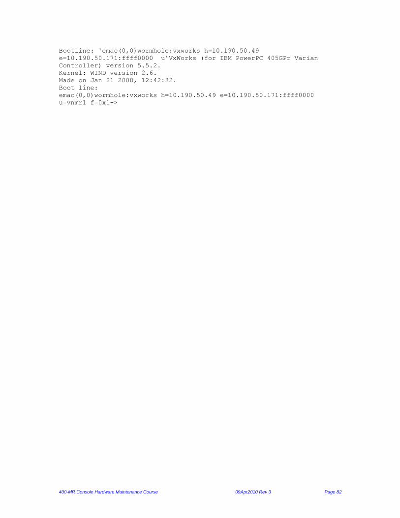
400-MR Console Hardware Maintenance Course 09Apr2010 Rev 3 Page 82
BootLine: 'emac(0,0)wormhole:vxworks h=10.190.50.49
e=10.190.50.171:ffff0000 u'VxWorks (for IBM PowerPC 405GPr Varian
Controller) version 5.5.2.
Kernel: WIND version 2.6.
Made on Jan 21 2008, 12:42:32.
Boot line:
emac(0,0)wormhole:vxworks h=10.190.50.49 e=10.190.50.171:ffff0000
u=vnmr1 f=0x1->

400-MR Console Hardware Maintenance Course 09Apr2010 Rev 3 Page 83
Bootup messages for DDR1 on VJ 2.3A: Welcome to minicom 2.00.0
OPTIONS: History Buffer, F-key Macros, Search History Buffer, I18n
Compiled on Jun 15 2004, 21:09:30.
Press CTRL-A Z for help on special keys
GPIO IR: 0x21068000
GEO: Type 5, (0x5), Address: 0, (0x0)
Varian visionWARE v2.1 PPC405GPR Controller Board
Build #32, 01/20/05 16:10:00
MAC : 00-60-93-03-50-01 IP : 10.190.50.171
Type "shell" to set IP and/or MAC addresses
Type "help" to see available commands
Press a key in the next <4> seconds to preempt boot script
Booting from script...
load vxWorks405gpr.bdx! launch 10000
CPC0_CR0: 0x383a
CPC0_CR0: 0x83a
CPC0_CR0: 0x383a
OsParams Address: 0x3e57964
Signature: 'vWARE', Version: 2
pVwareEntry: 0x3e22710, Func Table Addr: 0x3e032c8
sysLanIbmEmacEnetAddrGet: Vware started
Attached TCP/IP interface to emac unit 0
Attaching network interface lo0... done.
sysResolveIpAddr(); MAC: 00:60:93:03:50:01:
sysResolveIpAddr(); RARP request sent, waiting for reply
++++++++++++++++++++++++ rarpInputHook +++++++++++++++++++++++++++++
packet length: 60
EtherHeader Source MAC: 00:12:3f:6f:04:0b
EtherHeader Destination MAC: 00:60:93:03:50:01
EtherHeader type: 0x8035 (0x8035-rarp, 0x806-arp, 0x800-ip
ARP Type: 4 (ARP_REQUEST=1, ARP_REPLY=2 RARP_REQUEST=3 RARP_REPLY=4)
Src MAC: 00:12:3f:6f:04:0b
Src IP: 172.16.0.1
Target MAC: 00:60:93:03:50:01
target IP: 172.16.0.50
Target MAC: 00:60:93:03:50:01
Local MAC: 00:60:93:03:50:01
resolved IP: 172.16.0.50
++++++++++++++++++++++++ +++++++++++++++++++++++++++++
sysResolveIpAddr(); MAC: 00:60:93:03:50:01:

400-MR Console Hardware Maintenance Course 09Apr2010 Rev 3 Page 84
sysResolveIpAddr(); RARP request sent, waiting for reply
sysResolveIpAddr(); MAC: 00:60:93:03:50:01:
sysResolveIpAddr(); RARP request sent, waiting for reply
sysResolveIpAddr(); RARP Reply IP: '172.16.0.50'
Target: 'ddr1', IP: '172.16.0.50'
Host: 'wormhole', IP: '172.16.0.1'
Skip DHCP Request.
Adding 4317 symbols for standalone.
CPU: IBM PowerPC 405GPr Varian
Controller. Proc. Memory Size: 0x2000000.
BSP version 1.2/7.
WDB Comm Type: WDB_COMM_END
WDB: Ready.
FFS file 'nvScript' opened, 1025 bytes
Executing FFS startup script 'nvScript' ...
#
nvld "/tftpboot/nddslib.o"
FFS file 'nddslib.o' opened, 5844541 bytes
value = 20552520 = 0x1399b48
nvld "/tftpboot/nvlib.o"
FFS file 'nvlib.o' opened, 754122 bytes
value = 25642904 = 0x1874798
nvrdate("wormhole")
value = 0 = 0x0
date
WED JUL 29 18:29:58 2009
value = 25 = 0x19
#
# systemInit(NetworkDisk_BasePath, BringUp_Level, DebugLevel,
ConsoleType, Flag)#
# NetworkDisk_BasePath - if NULL then the bit and exec files are loaded
from flh# Otherwise used as the directory on the
network drive to .# e.g. NetworkDisk_BasePath = /tftpboot
/tftpboot/xxxexec.o are loaded
#
# systemInit("/tftpboot",0,1,0,0) load bit and exec.o from
/tftpboot
#
# BringUp_Level - level of software service, etc. started
# 0 = only dma drivers initialized.
# 1 = DMA, NDDS, initialized
# Bringup is called.
# 2-9 Reserved for future use.
#
# DebugLevel - Level of Diagnostic Output, 0 = None, 1 - minimum,
# 2 - NDDS output, 3-10 more
output
#
# ConsoleType - Type of console , used to load proper varient of FPGA
# 0 = VNMRS (a.k.a. Nirvana)
#
# Flags - reserved for special purposes
# 0 = default
#
systemInit(0,1,-2,0,0)

400-MR Console Hardware Maintenance Course 09Apr2010 Rev 3 Page 85
emac0 previous queue length was 50
Queue length set at: 200
IP input maximum queue length = 50
Arp input maximum queue length = 50
New IP input maximum queue length = 200
New Arp input maximum queue length = 50
GPIO IR: 0x2306be00
GEO: Type 5, (0x5), Address: 0, (0x0)
------- systemInit createDomain
hostname : 'ddr1'
IP val: 0xac100032
Local IP: '172.16.0.50'
File: '(null)/ddr_top.bit' not found on FFS.
18:29:58++++++ Loading Exec file: 'ddrexec.o'
FFS file 'ddrexec.o' opened, 675938 bytes
loadFpgaArray(): addr: 0x15ddaa0, size: 510398
Sending configuration data to FPGA
FPGA Configuration Successful.
Reseting FPGA via GPIO line.
18:30:00 FPGA ID: 5, Rev: 0, Chksum: 61213; ddr.c Chksum: 61213,
Compiled: Ma918:30:00 FPGA ID: 5, Rev: 0, Chksum: 61213; ddr.c
Chksum: 61213, Compiled: Ma9reg ptr: 0x15ab86c, Int mask: 0x130f, instr
fifo size: 1024
18:30:00 'cntrlFifoBufObj.c' line: 98, fifoBufCreate(): Creating
msgQs of 128smask: 0xf0
File: 'boot.bin' not found
File: 'ddr.bin' not found
18:30:01 'DDR_Init.c' line: 642, MULT:11 DIV1:2 CPU:1080786944 MHz
18:30:01 'DDR_Init.c' line: 659, MULT:11 DIV3:5 EMIF:1079377920 MHz
18:30:01++++++ BringUp Complete..
18:30:01 - System Version: 1
18:30:01 - Interpreter Version: 1
18:30:01 - Bootup Complete.
value = 0 = 0x0
Done executing startup script /tftpboot/nvScript
sysVwareParamsGet: ulp: 0x12fbc0, *ulp: 0x1badc0de
(global environment)
0: NDDS_PEER_HOSTS=wormhole
BootLine: 'emac(0,0)wormhole:vxworks h=10.190.50.49
e=10.190.50.171:ffff0000 u'VxWorks (for IBM PowerPC 405GPr Varian
Controller) version 5.5.2.
Kernel: WIND version 2.6.
Made on Jan 21 2008, 12:42:32.
Boot line:
emac(0,0)wormhole:vxworks h=10.190.50.49 e=10.190.50.171:ffff0000
u=vnmr1 f=0x1->

400-MR Console Hardware Maintenance Course 09Apr2010 Rev 3 Page 86
Resolving Communication Issues Purpose This section teaches you about possible console communication issues with the host PC running Linux.
Refer to the “Controller Initialization” procedure as needed to do some of the trouble shooting discussed
here.
Equipment needed The following equipment is required to perform these tests:
9F-9F null modem cable
How to trouble shoot a communication issue: Controller bootup process Each controller has a unique IP address. At bootup the PPC executes software in flash that initializes the
PPC GPIO lines. These lines read the type bits of the IF card to dynamically configure the MAC address of
each controller. VxWorks then uses RARP to obtain an IP for the controller. Controller boots from
firmware in flash memory. The PPC then executes nvlib.o, which uses the GPIO lines to read the type bits
(set by the IF card or 3 jumpers) to configure the FPGA, which completes the bootup.
General tips to keep in mind 1. Info about setacq:
a) Setacq cannot load files into a blank controller. All controllers need to boot up completely for
setacq to download files. If a controller does not boot, setacq will hang and not download
to the rest of the controllers.
b) Setacq will not re-flash a controller a second time if it has been done once on the same system
and patch level. It simply verifies if a controller’s firmware matches the version in
/vnmr/acq/download. Verification is indicated by the DS5 flashing once per file checked
& takes about a minute to check all files on all controllers.
c) A full download of 9 files for all controllers takes about 7-8 minutes. During the downloading,
the yellow LEDs on all controllers blink in sync in a unique pattern per file downloaded.
During this process you must not reset the master as this can erase some or all firmware
in the controllers.
2. All controllers can bootup without the 80 MHz clock, but the clock is needed to get “setup complete”. If
the clock is missing to any controller, an “su” results in a hangup with the message:
“pulse sequence required controller(s) are unresponsive in initial synch”
Note:
Once the system is “idle”, a “setup complete” can be achieved only if all controllers have the 80 MHz clock
input. You can even achieve “setup complete” without any connection to the pneumatic router, RFFE unit
or MIF.
3. If a controller did not bootup or “cpu_err” LED is on:
a) Ensure the IF card power LED is lit. If it is off, this indicates improper seating.

400-MR Console Hardware Maintenance Course 09Apr2010 Rev 3 Page 87
b) Reseat the controller
c) Re-flash the controller using the “Controller Initialization” procedure
Issue: System is “inactive” Check the setup and status of the network cards: Click applications, system settings, network. Enter the root password. In the pop up window check the following: 1. eth1 (mother-board card):
IP=172.16.0.1 (or 10.0.0.1) and subnet=255.255.255.0
Make sure status is active
Make sure it is connected to the console’s Ethernet port which connects to the 1 MB port
on the hub.
2. eth0 (card slot):
IP and subnet = (set by your IT)
Make sure status is active
Make sure it is connected to the LAN with their network info. The eth0 cannot be named
wormhole and should be active even if not connected to any LAN.
3. Save any changes
Note:
Any change in the network info requires that you re-run setacq
Check if you can ping wormhole, master1 & DDR1: In a terminal window type:
1. ping wormhole : should result in “64 bytes from wormhole (172.16.0.1): icmp…….” repeatedly
2. ping master1 (or ddr1) : should result in “64 bytes from master1 (or ddr1)…..” repeatedly
If pinging a controller fails:
If ping fails you see: “from wormhole (172.16.0.1) …. Destination Host unreachable”.
If rlogin fails, you see: “….no route to host”
TO PING OR RLOGIN INTO A CONTROLLER, IT NEEDS 3 THINGS:
1. The rarp demon must be running (see section below “Check if setacq does the following”)
2. boot.ini must have the correct network info (see “Controller Initialization” procedure)
3. VxWorks must be running
Note: You may successfully ping or rlogin into a controller, yet it may not bootup completely if some files are
missing such as nvScript, nvlib.o, & its exec.o file.

400-MR Console Hardware Maintenance Course 09Apr2010 Rev 3 Page 88
Check if master1 and DDR1 have booted completely: To achieve “idle” status, both the master and DDR must bootup. If any other controller does not
boot up, the system will still go “idle”.
FOR A CONTROLLER TO BOOTUP & FUNCTION, IT NEEDS 3 things
1. Power: 5V & 3.3V for the controller and 7.6V & +/-15V for the mezzanines
2. Certain firmware files: boot.ini, vxWorks405gpr.bdx, nvlib.o, nvScript and X (where X is one
execution file such as masterexec.o, rfexec.o, gradientexec.o, pfgexec.o, lockexec.o,
ddrexec.o)
Note: All files are present to enable them to change function depending on slot location.
3. A properly seated IF card (its power LED is on), whose type bits determine controller
functionality
Note:
Use the “Controller Initialization” procedure to check the bootup messages and re-flash the
master1 and/or DDR1 if they do not boot.
IF THE MASTER1 OR DDR1 REBOOT THEMSELVES, CHECK THE FOLLOWING:
1. Make sure power to the board is within specs as measured on the side of the power supply.
2. Multiple interrupts from other sources such as the current driver or RFFE board will reset the
interrupted controller. This can be monitored by rlogin then typing: DebugLevel=1
as shown in a previous section
You will clearly see “interrupt….” if that is happening.
If setacq fails, try the following: 1. Re-run setacq a 2nd time. The tftp demaon may not have started the first time.
2. Swap network cards:
a. Connect the console to the card slot instead of the mother board card.
b. Swap the network info on both cards using the network GUI.
c. Run setacq by using /vnmr/bin/setacq eth0
3. Connect the host directly to the Ethernet switch (bypassing back connector)
4. Remove any external router or hub
5. Use another Ethernet cable. It can be straight thru or with crossed wires
6. Check for TCP wrappers:
If the /etc/hosts.deny file exists, it may list some or all IP addresses that are not allowed to
connect to the PC. If it exists, makes sure that the /etc/hosts.allow file exists having the IP
addresses of all controllers & wormhole.
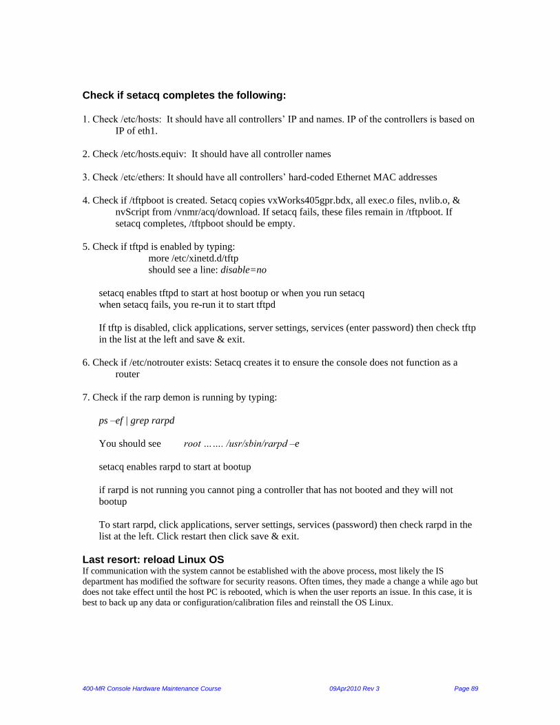
400-MR Console Hardware Maintenance Course 09Apr2010 Rev 3 Page 89
Check if setacq completes the following: 1. Check /etc/hosts: It should have all controllers’ IP and names. IP of the controllers is based on
IP of eth1.
2. Check /etc/hosts.equiv: It should have all controller names
3. Check /etc/ethers: It should have all controllers’ hard-coded Ethernet MAC addresses
4. Check if /tftpboot is created. Setacq copies vxWorks405gpr.bdx, all exec.o files, nvlib.o, &
nvScript from /vnmr/acq/download. If setacq fails, these files remain in /tftpboot. If
setacq completes, /tftpboot should be empty.
5. Check if tftpd is enabled by typing:
more /etc/xinetd.d/tftp
should see a line: disable=no
setacq enables tftpd to start at host bootup or when you run setacq
when setacq fails, you re-run it to start tftpd
If tftp is disabled, click applications, server settings, services (enter password) then check tftp
in the list at the left and save & exit.
6. Check if /etc/notrouter exists: Setacq creates it to ensure the console does not function as a
router
7. Check if the rarp demon is running by typing:
ps –ef | grep rarpd
You should see root ……. /usr/sbin/rarpd –e
setacq enables rarpd to start at bootup
if rarpd is not running you cannot ping a controller that has not booted and they will not
bootup
To start rarpd, click applications, server settings, services (password) then check rarpd in the
list at the left. Click restart then click save & exit.
Last resort: reload Linux OS If communication with the system cannot be established with the above process, most likely the IS
department has modified the software for security reasons. Often times, they made a change a while ago but
does not take effect until the host PC is rebooted, which is when the user reports an issue. In this case, it is
best to back up any data or configuration/calibration files and reinstall the OS Linux.

400-MR Console Hardware Maintenance Course 09Apr2010 Rev 3 Page 90
Console Hardware Checks
Purpose This section teaches you how to check console functionality. There are two major
sections: transmit and receive paths. Each section checks the entire path and breaks the
path into sections to isolate the issue.
Note:
For the latest updates on the console checks, refer to the “Console Checks” document on
the Tech Support website.
Equipment needed The following equipment is required to perform these tests:
Oscilloscope 400 MHz or higher
Signal generator
30dB attenuator
Transmit and Receive Signal Flow Diagram

400-MR Console Hardware Maintenance Course 09Apr2010 Rev 3 Page 91
Transmitter Paths Tests Note: The results of the transmit path tests below can vary depending on the length of cable used & max
frequency of the scope. Measuring higher frequencies (H1) than the scope can handle or excessively long
cables (try to use the lock cable) will result in lower measurements.
Testing the High band and Low band signal paths
1. Retrieve the H1sn parameters from /home/vnmr/parX00/tests & set these parameters (the par X00 refers
to par400, par500, etc) and type
pw=30 d1=0.1 at=0.2 nt=1e6 in=’n’ dp=’y’
tn=’H1’ when measuring proton (and set set dn=’C13’)
tn=’C13’ when measuring carbon (and set dn=’H1’)
Caution:
Please use caution so as not to damage the scope or NMR probe
No attenuator is needed when measuring the VFS, transmitter or attenuator board outputs. The
attenuator is needed when measuring at the RF amp outputs or at the probe.
set tpwr=31 when NOT using a 30dB attenuator and measuring at the RF amp output or probe
set tpwr=63 when using a 30dB attenuator or when measuring the Attenuator Board outputs.
2. After typing go, measure the following ports using the 50-ohm scope setting:
A. VFS synthesizer Ch1/Ch2 ports (without pads) : >2.5Vpp
B. Synthesizer board Ch1/Ch2: 2.18V – 3.26 V
B. Transmitter boards J2X3 port (H1 is always transmitter#1 on right): C13/H1: 1.26 – 2Vpp
C. Attenuator board (tpwr=63 & no attenuator used) ports: J297 (H1) or J298 (C13)/ RF AMP CH1/CH2
input ports: >530 mVpp
D. RF amplifier output ports:
High Band: > 2.6Vpp
Low Band: > 11.6Vpp
E. Measurements at the cable (H1 or C13 or lock) that attaches to the probe:
H1: >= 2.5Vpp (typical: 3V)
C13: >= 11.5Vpp (typical: 13V)
Lock cable: tn=’lk’: >=8V (typ: 9V)
To Test the Lock Transmit Path 1. In the lock screen set lockpower to max & measure
Lock Transceiver output J227 port: > 3Vpp
2. Lock signal at the probe lock cable: >1.1V (50-ohm setting) and pulse has a width of 5 msec when lock
scan ON or 50usec when off
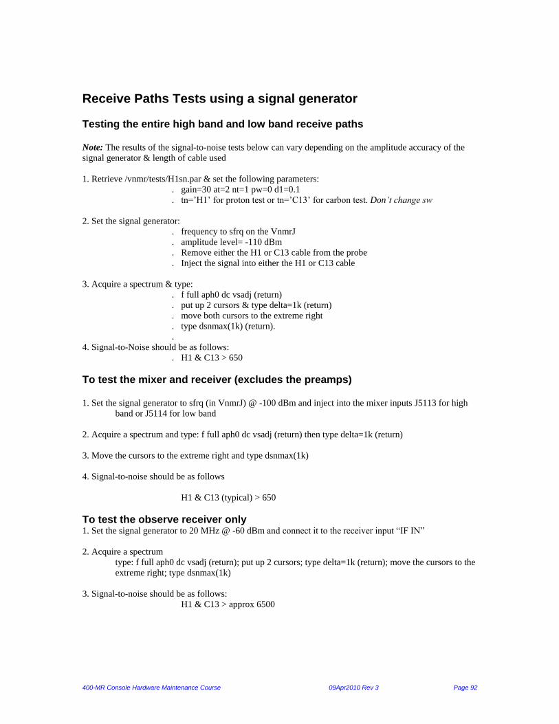
400-MR Console Hardware Maintenance Course 09Apr2010 Rev 3 Page 92
Receive Paths Tests using a signal generator Testing the entire high band and low band receive paths Note: The results of the signal-to-noise tests below can vary depending on the amplitude accuracy of the
signal generator & length of cable used
1. Retrieve /vnmr/tests/H1sn.par & set the following parameters:
. gain=30 at=2 nt=1 pw=0 d1=0.1
. tn=’H1’ for proton test or tn=’C13’ for carbon test. Don’t change sw
2. Set the signal generator:
. frequency to sfrq on the VnmrJ
. amplitude level= -110 dBm
. Remove either the H1 or C13 cable from the probe
. Inject the signal into either the H1 or C13 cable
3. Acquire a spectrum & type:
. f full aph0 dc vsadj (return)
. put up 2 cursors & type delta=1k (return)
. move both cursors to the extreme right
. type dsnmax(1k) (return).
.
4. Signal-to-Noise should be as follows:
. H1 & C13 > 650
To test the mixer and receiver (excludes the preamps) 1. Set the signal generator to sfrq (in VnmrJ) @ -100 dBm and inject into the mixer inputs J5113 for high
band or J5114 for low band
2. Acquire a spectrum and type: f full aph0 dc vsadj (return) then type delta=1k (return)
3. Move the cursors to the extreme right and type dsnmax(1k)
4. Signal-to-noise should be as follows
H1 & C13 (typical) > 650
To test the observe receiver only 1. Set the signal generator to 20 MHz @ -60 dBm and connect it to the receiver input “IF IN”
2. Acquire a spectrum
type: f full aph0 dc vsadj (return); put up 2 cursors; type delta=1k (return); move the cursors to the
extreme right; type dsnmax(1k)
3. Signal-to-noise should be as follows:
H1 & C13 > approx 6500

400-MR Console Hardware Maintenance Course 09Apr2010 Rev 3 Page 93
Lock Receiver Path To test entire lock receive path (lock filter, diplexor, lock preamp, lock transceiver, and lock controller ADC) 1. Open the lock screen window and set lockpower=0, lockgain=max
2. On the command line type: lockfreq?
3. Set the signal generator to the lockfreq value at -110dBm
4. Remove the cable from the probe’s lock port
5. Inject the signal into the lock cable at the probe
6. Make sure you see a saturated/clipped, slightly off-resonance lock sinewave
. (If sinewave is not clipped, the receive path may have a problem)
To test the lock receive path only (separate from the lock controller ADC) If the signal injection at the probe does not give a clipped signal or gives no signal (flat line), do the
following:
1. Set the signal generator to –110 dBm at lockfreq value
2. Inject into lock cable, then measure any of the lock transceiver ports J223, J224, or J225. Each connector
has 6 pins: 3 on top & bottom of the notch. The middle pin (at 12 o’clock & 6 o’clock) you should get
>10Vpp using 1Mohm at max lock gain (also nmr lock signal is clipped).
To test the lock transceiver only (separate from the lock filter, diplexor, lock preamp, and lock controller ADC)
Inject –70 dBm @ lockfreq into lock transceiver J229 port
Measure J223, 224, or 225. Each connector has 6 pins: 3 on top & bottom of the notch. The signal to
measure is on the middle pin (at 12 o’clock & 6 o’clock).
Expect to get >4Vpp using 1Mohm at max lock gain.
Mtune Mtune is a very quick check of the console. You should see a clean signal on screen when the probe cables
are disconnected. A clean line means most of the console is functioning. It does not test the mixer’s HB,
LB, or lk inputs—only tune input. It also does not use the preamp receive path.
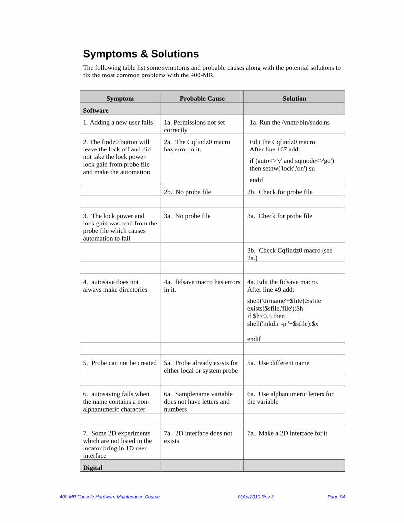
400-MR Console Hardware Maintenance Course 09Apr2010 Rev 3 Page 94
Symptoms & Solutions The following table list some symptoms and probable causes along with the potential solutions to
fix the most common problems with the 400-MR.
Symptom Probable Cause Solution
Software
1. Adding a new user fails 1a. Permissions not set
correctly
1a. Run the /vnmr/bin/sudoins
2. The findz0 button will
leave the lock off and did
not take the lock power
lock gain from probe file
and make the automation
2a. The Cqfindz0 macro
has error in it.
Edit the Cqfindz0 macro.
After line 167 add:
if (auto<>'y' and sqmode<>'go')
then sethw('lock','on') su
endif
2b. No probe file 2b. Check for probe file
3. The lock power and
lock gain was read from the
probe file which causes
automation to fail
3a. No probe file 3a. Check for probe file
3b. Check Cqfindz0 macro (see
2a.)
4. autosave does not
always make directories
4a. fidsave macro has errors
in it.
4a. Edit the fidsave macro.
After line 49 add:
shell('dirname'+$file):$sfile
exists($sfile,'file'):$h
if $h<0.5 then
shell('mkdir -p '+$sfile):$x
endif
5. Probe can not be created 5a. Probe already exists for
either local or system probe
5a. Use different name
6. autosaving fails when
the name contains a non-
alphanumeric character
6a. Samplename variable
does not have letters and
numbers
6a. Use alphanumeric letters for
the variable
7. Some 2D experiments
which are not listed in the
locator bring in 1D user
interface
7a. 2D interface does not
exists
7a. Make a 2D interface for it
Digital

400-MR Console Hardware Maintenance Course 09Apr2010 Rev 3 Page 95
1. Console is Inactive 1a. No power to console 1a. Check power and fuses
1b. Setacq was not run 1b. Run setacq
1c. Exproc not running 1c. Start Exproc: “su acqproc”
1d. Cable not connected 1d. Check Ethernet cable
1e.
2. No VFS output 2a.Config file not
configured correctly
2a. Set Synthesizer to Direct
Digital
2b. GIC board has bad T1-
T4 J-head solder joint.
2b. Replace the GIC board
RF
1. Long Pulse Widths 1a. Amplifier low output 1a. Check output of Amplifiers
1b. Probe not tuned 1b. Tune probe
1c.
2. Low Signal to Noise 2a. Not using correct PW 2a. Use correct PW
2b. Not shimmed properly 2b. Shim the system more
2c. Pre Amp not working 2c. Check Voltages and T/R
3. Will not lock on sample 3a. Wrong lock frequency 3a. Use correct lock frequency
3b. Wrong Lock Polarity 3b. Change Lock Polarity Switch.
4. Distorted H1 spectra:
dips below peak at usual
power but ok at 35 or
40…gain makes no diff
(base changes)…fid
appears clipped & both
real/imag start at same
point (not offset by 90deg).
4a. Bad preamp 4a. Check or replace Preamp
4b. Bad Mixer 4b. Check or replace Mixer
4c. Bad Receiver 4c. Check or replace Receiver
4d. Bad probe 4d. Check and repair probe
Pneumatics

400-MR Console Hardware Maintenance Course 09Apr2010 Rev 3 Page 96
1. Sample will not eject 1a. Not enough eject air
1a. Adjust the Upperbarrel
Regulator while trying to eject the
sample.
2. Sample will not insert
2a. Too much bearing gas,
"liqbear" parameter set
incorrectly
2a. Create and set "liqbear", value
also stored in probe file, if probe
file already existed, do an update
probe file. See "liqbear" in the
command and parameter reference
manual.
3. Sample will not spin
3. Not enough bearing gas,
"liqbear" parameter set
incorrectly.
3. Create and set "liqbear", value
also stored in probe file, if probe
file already existed, do an update
probe file. See "liqbear" in the
command and parameter reference
manual.
4. Sample does not stop
spinning
4a. Too much bearing gas,
"liqbear" parameter set
incorrectly
4a. Create and set "liqbear", value
also stored in probe file, if probe
file already existed, do an update
probe file. See "liqbear" in the
command and parameter reference
manual.
5. Sample present light
does not turn on when
sample is present
5a. "Sample Sensor"
adjustment on the PFE
Board.
5a. With a sample in the magnet
adjust the "Sample Sensor" pot so
that the "Sample Bottom" LED
lights, eject the sample and verify
that the "Sample Bottom" LED
turns off. Re-adjust knob if
necessary.
6. Sample present light
does not turn off when
sample is not present
6a. "Sample Sensor"
adjustment on the PFE
Board.
6a. With a sample in the magnet
adjust the "Sample Sensor" R95 on
the PFE bd, so that the "Sample
Bottom" LED lights, eject the
sample and verify that the "Sample
Bottom" LED turns off. Re-adjust
R95 if necessary.
7. Cannot run a VT
experiment, Red Led
always on the VT
controller.
7a. Pneumatics Fault line
has tripped.
7a. Reset the VT controller by
pressing the "Reset VT" software
button in vnmrj.
7b. Pneumatics Fault line
has tripped.
7b. Reset the Pneumatics Router
by pressing the "Reset Pneumatics"
software button in vnmrj.
8. Cannot find the "Reset
Pneumatics" button in
Vnmrj software panel
8a. Using non-standard or
custom software panels
8a. sethw('pneufault','clear') from
command line.
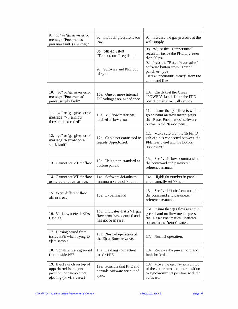
400-MR Console Hardware Maintenance Course 09Apr2010 Rev 3 Page 97
9. "go" or 'ga' gives error
message "Pneumatics
pressure fault (< 20 psi)"
9a. Input air pressure is too
low.
9a. Increase the gas pressure at the
wall supply.
9b. Mis-adjusted
"Temperature" regulator
9b. Adjust the "Temperature”
regulator inside the PFE to greater
than 30 psi.
9c. Software and PFE out
of sync
9c. Press the "Reset Pneumatics"
software button from "Temp"
panel, or, type
"sethw('pneufault','clear')" from the
command line
10. "go" or 'ga' gives error
message "Pneumatics’
power supply fault"
10a. One or more internal
DC voltages are out of spec.
10a. Check that the Green
"POWER" Led is lit on the PFE
board, otherwise, Call service
11. "go" or 'ga' gives error
message "VT airflow
threshold exceeded"
11a. VT flow meter has
latched a flow error.
11a. Insure that gas flow is within
green band on flow meter, press
the "Reset Pneumatics" software
button in the "temp" panel.
12. "go" or 'ga' gives error
message "Narrow bore
stack fault"
12a. Cable not connected to
liquids Upperbarrel.
12a. Make sure that the 15 Pin D-
sub cable is connected between the
PFE rear panel and the liquids
upperbarrel.
13. Cannot set VT air flow 13a. Using non-standard or
custom panels
13a. See "vtairflow" command in
the command and parameter
reference manual
14. Cannot set VT air flow
using up or down arrows
14a. Software defaults to
minimum value of 7 lpm.
14a. Highlight number in panel
and manually set >7 lpm
15. Want different flow
alarm areas 15a. Experimental
15a. See "vtairlimits" command in
the command and parameter
reference manual.
16. VT flow meter LED's
flashing
16a. Indicates that a VT gas
flow error has occurred and
has not been reset.
16a. Insure that gas flow is within
green band on flow meter, press
the "Reset Pneumatics" software
button in the "temp" panel.
17. Hissing sound from
inside PFE when trying to
eject sample
17a. Normal operation of
the Eject Booster valve. 17a. Normal operation.
18. Constant hissing sound
from inside PFE.
18a. Leaking connection
inside PFE
18a. Remove the power cord and
look for leak.
19. Eject switch on top of
upperbarrel is in eject
position, but sample not
ejecting (or vise-versa)
19a. Possible that PFE and
console software are out of
sync.
19a. Move the eject switch on top
of the upperbarrel to other position
to synchronize its position with the
software.
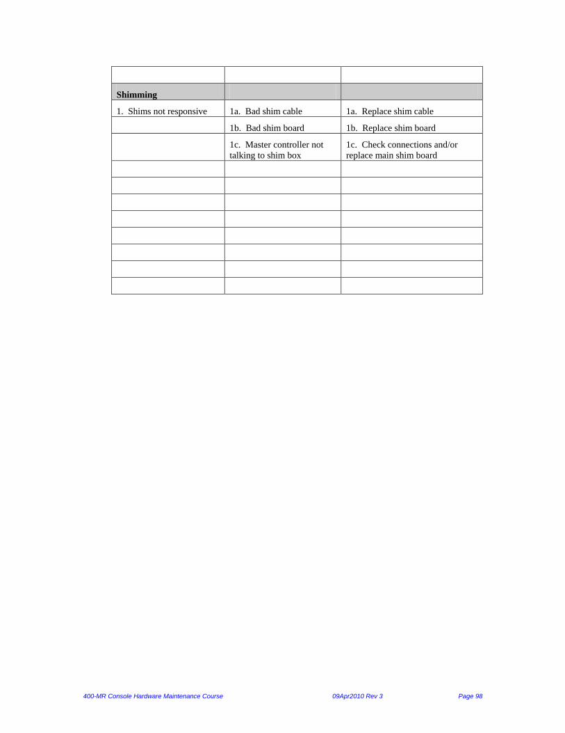
400-MR Console Hardware Maintenance Course 09Apr2010 Rev 3 Page 98
Shimming
1. Shims not responsive 1a. Bad shim cable 1a. Replace shim cable
1b. Bad shim board 1b. Replace shim board
1c. Master controller not
talking to shim box
1c. Check connections and/or
replace main shim board
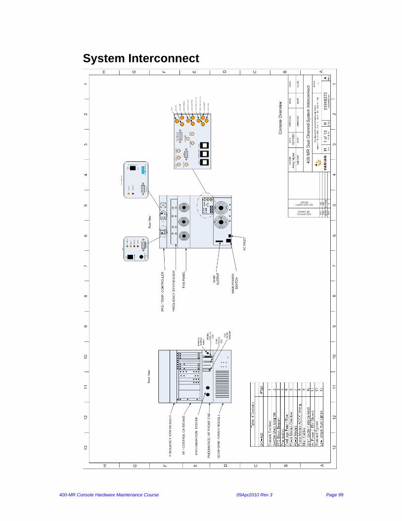
400-MR Console Hardware Maintenance Course 09Apr2010 Rev 3 Page 99
System Interconnect
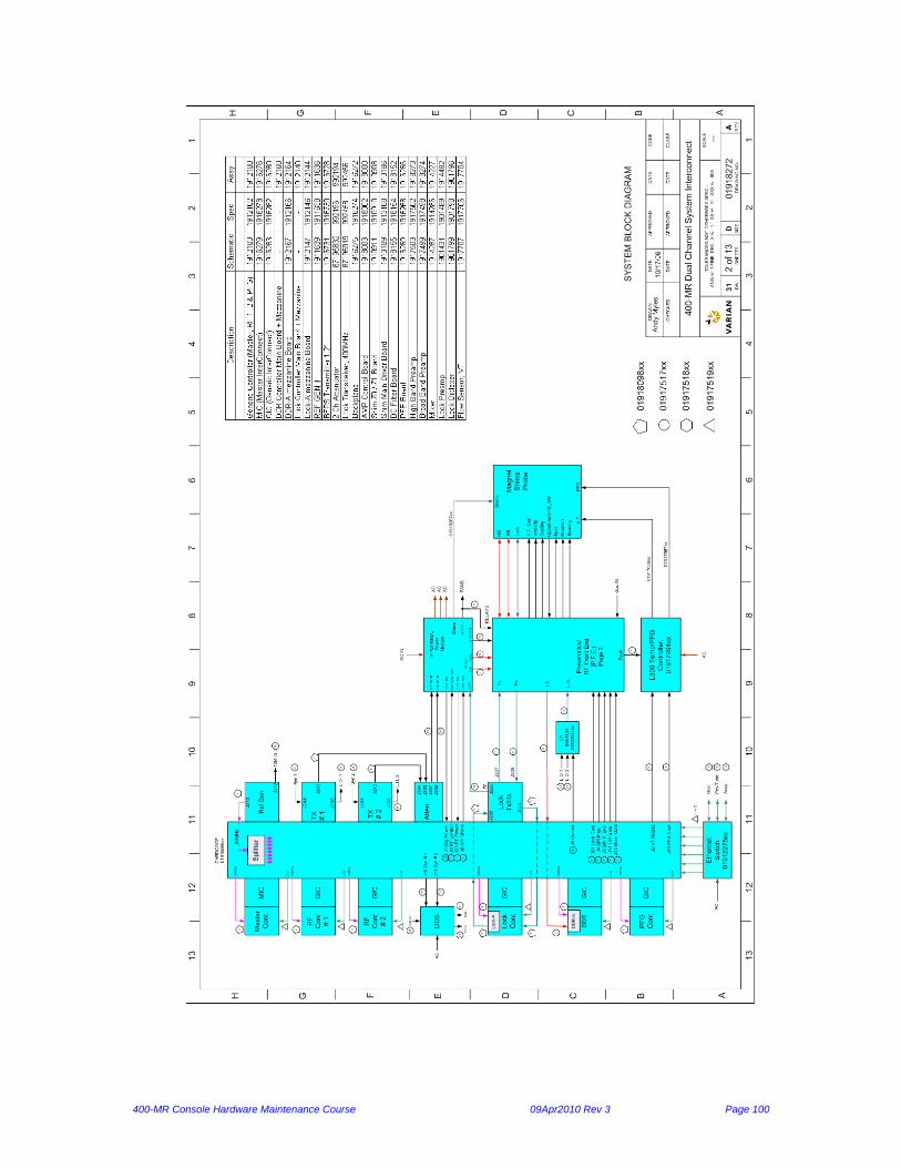
400-MR Console Hardware Maintenance Course 09Apr2010 Rev 3 Page 100

400-MR Console Hardware Maintenance Course 09Apr2010 Rev 3 Page 101
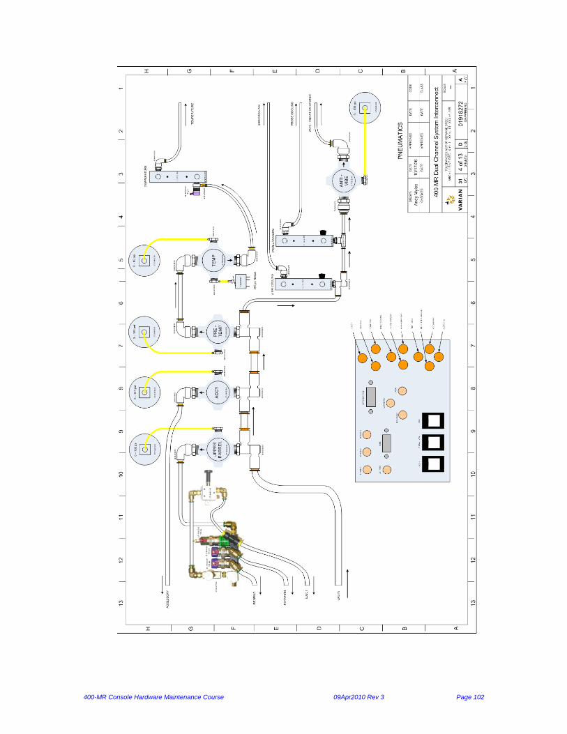
400-MR Console Hardware Maintenance Course 09Apr2010 Rev 3 Page 102
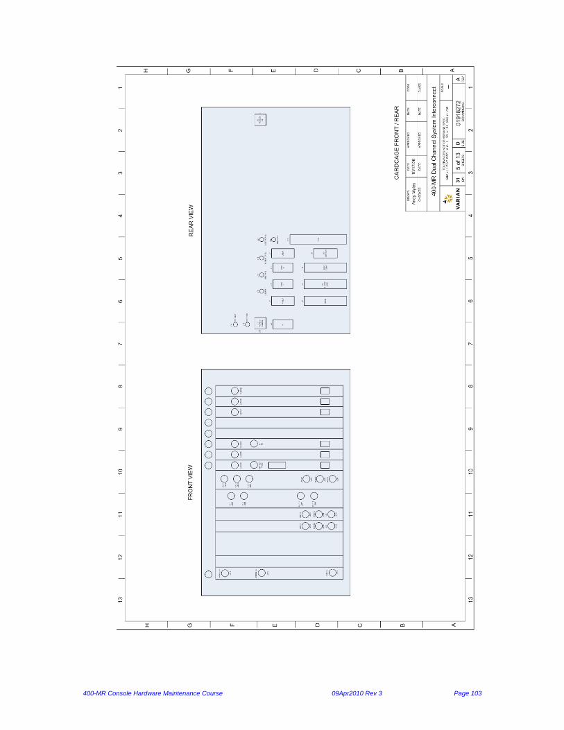
400-MR Console Hardware Maintenance Course 09Apr2010 Rev 3 Page 103
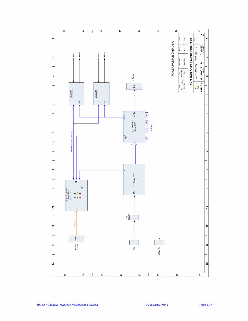
400-MR Console Hardware Maintenance Course 09Apr2010 Rev 3 Page 104

400-MR Console Hardware Maintenance Course 09Apr2010 Rev 3 Page 105

400-MR Console Hardware Maintenance Course 09Apr2010 Rev 3 Page 106

400-MR Console Hardware Maintenance Course 09Apr2010 Rev 3 Page 107

400-MR Console Hardware Maintenance Course 09Apr2010 Rev 3 Page 108

400-MR Console Hardware Maintenance Course 09Apr2010 Rev 3 Page 109

400-MR Console Hardware Maintenance Course 09Apr2010 Rev 3 Page 110

400-MR Console Hardware Maintenance Course 09Apr2010 Rev 3 Page 111