3/29/2016 and clean-air separator installation on a … corvette... · and. clean-air separator...
TRANSCRIPT
1
3/29/2016
Catch Can and
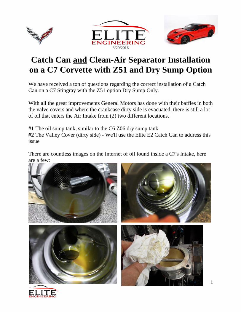
Clean-Air Separator Installation on a C7 Corvette with Z51 and Dry Sump Option We have received a ton of questions regarding the correct installation of a Catch Can on a C7 Stingray with the Z51 option Dry Sump Only. With all the great improvements General Motors has done with their baffles in both the valve covers and where the crankcase dirty side is evacuated, there is still a lot of oil that enters the Air Intake from (2) two different locations. #1 The oil sump tank, similar to the C6 Z06 dry sump tank #2 The Valley Cover (dirty side) - We'll use the Elite E2 Catch Can to address this issue There are countless images on the Internet of oil found inside a C7's Intake, here are a few:

2
For many reasons, we DON'T want to completely delete GM's current PCV System, we just want to improve its functionality and performance. The 1st thing to address is the Clean-Side. The Clean-side solution addresses that small amount of oil vapor that enters the intake air charge upstream of the throttle body during WOT operation when the intake manifold vacuum is not present.
The Clean side solution allows 100% MAF metered air entry while trapping the oil during wide open throttle operation and allowing it to return back into the valve cover as soon as the throttle is lifted.

3
Simply installs as a direct replacement for your stock Oil Fill Cap allowing you to Tie/Tee into the existing stock OEM hose.

4
Tee shown below and hose from branch of Tee to Dry Sump Port “A”

5
At 1/2 the cost of the plastic hollow GM unit, our aluminum clean-side separator incorporates an internal coalescing material. Simply unscrew the top for a quick inspection or cleaning. The Passenger's Side Valve Cover has two fittings that join the vent through the dry sump tank and also connect to the air box pictured below, this is where the Clean-Air Separator is installed. The Clean-Side Separator will trap the oil that "burps" and will hold it and prevent it from being ingested. Any oil trapped with find its way back during full vacuum or normal deceleration or idle. Added to the Elite original Catch Can, or New E2 Catch Can, this is your COMPLETE
PCV Oil Ingestion Solution.

6
Now addressing the real problem area, the Dirty Side. Shown below, the filtered Mass Air Flow (MAF) fresh air enters the driver's side valve cover through this Main Air Box Line shown above. We'll leave this line untouched.
The best set-up/installation will utilize the 2nd Generation E2 Catch Can with Dual Exit Ports and (2x) Check Valves. Shown below with Electroless Nickel Fittings or Black AN Fittings.

7
This U shaped fitting shown below runs from the Intake Manifold Vacuum Barb down to the Valley Cover Barb. We'll remove this U-shaped fitting and Splice in the E2 Catch Can here.

8
Mount the E2 Catch Can here, using the supplied G8 Bracket

9
Now let's look at the connections on the (2) Exit Port Catch Can, pictured below:

10
Now we simply connect the Center Port on the E2 Catch Can to the Valley Barb "A" (and since it already is a check valve, no additional valve need be installed here) Now Connect (1) of the Side Exit Ports to the Vacuum Barb "B" left open after removing the U shaped stock tube, WITH a check valve flowing away from the can (this is to ensure no mixing and reversion)

11
Finally, for the 2nd Exit Port, you will need to drill a hole in the stock OEM plastic Coupler. Once drilled, thread in the supplied plastic Hose Barb x NPT fitting. This is where the 2nd exit port hose will connect, "C"
It's easiest to remove the Intake assembly and drill this on a workbench or tabletop "X" Marks the spot for the drill and installation of the supplied 1/4" fitting

12
Drilled hole shown below. We found it is best to NOT use a pilot drill, but carefully drill this out with a 3/8" drill bit. Shown below with drilled hole and ready for the 1/4" NPT fitting.
Picture below shows the 1/4" NPT x hose barb fitting threaded into the 3/8" drilled hole.

13
Picture below shows the hose attached to the 1/4" NPT x hose barb fitting. You are now ready to reinstall this inlet section and complete the hose connection at location "C"
14
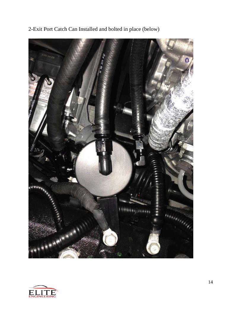
2-Exit Port Catch Can Installed and bolted in place (below)