centrifugal separator - fluid cooling systems, llc. · centrifugal separator pressure gauges inlet...
TRANSCRIPT

CENTRIFUGAL SEPARATORA FLUID COOLING SYSTEMS PRODUCT
A FLUID COOLING SYSTEMS PRODUCT
A FLUID COOLING SYSTEMS PRODUCT
fluidcoolingsystems.com/spirex

SPIREX ADVANTAGES
why FILTERA filtration system is a critical component to your cooling system, whether you are looking to clean up dirty water, or simply maintain the level of cleanliness. Left unfiltered, dirty water can foul heat transfer surfaces, making them less efficient and possibly causing damage to your cooling system. Filtration extends both the life of your system, and the life of the vital infrastructure being cooled, and requires less chemicals to treat.
CENTRIFUGAL SEPARATIONFor many applications, a centrifugal separator is the ideal solution for keeping your process cooling water clean. They are the perfect means of filtering out particulate matter prior to the supply of water in an industrial application, and are designed to last the life of your system.
SPIREx OvERvIEwThe Spirex Centrifugal Separator is a patent pending device intelligently designed to optimize separation while maximizing system efficiency. With an innovative design and durable construction, it’s the only choice for centrifugal separation applications.
ApplicAtions
industriesAutomotive, chemical processing, ethanol, food processing, fuel distribution, primary metals, process cooling, municipal services, vehicle wash, oil and gas, power plants, mining operations, pulp and paper mills.
DIFFERENTIATORSOur patent-pending design includes several key features that set us apart from the competition. First, our sloped inlet guide steers fluid tangentially around the vessel upon entry to maximize flow rates and separation. Second, our industry-first blade arrangement guides fluid flow around the vessel 2–3 times more than other separators, maximizing revolutions and gravitational force, which promotes finer/lighter particle separation. Lastly, our Flow Straightening Vanes bring ideal flow conditions into the pipe system.
• Open loop cooling tower systems
• Spray water systems used for closed circuit evaporative cooling towers
• Pre-filtration prior to a barrier style filter • Mechanical seal support systems
• Spray water nozzle applications • Quench tank recirculation systems
or cooling loops • River or lake water direct use
applications • Coolant loops
CENTRIFUGAL SEPARATOR
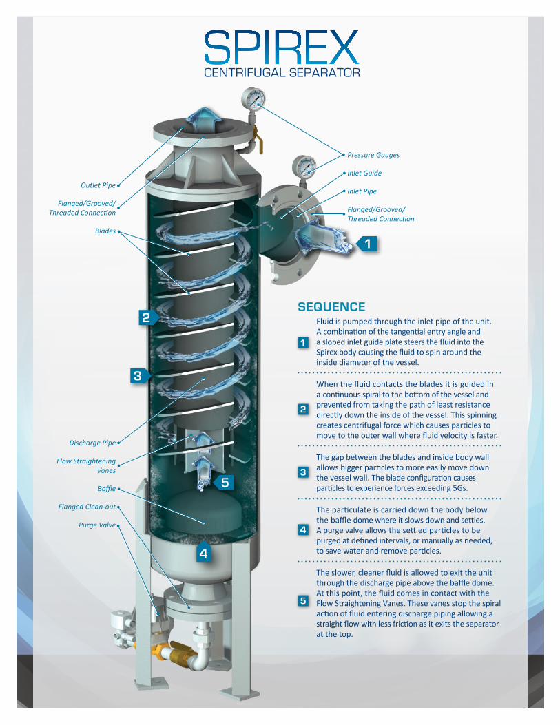
Pressure Gauges
Inlet Guide
Inlet Pipe
Blades
Flow Straightening Vanes
Flanged Clean-out
Baffle
Purge Valve
Discharge Pipe
Flanged/Grooved/ Threaded Connection
Flanged/Grooved/ Threaded Connection
Outlet Pipe
1
5
4
3
2
Fluid is pumped through the inlet pipe of the unit. A combination of the tangential entry angle and a sloped inlet guide plate steers the fluid into the Spirex body causing the fluid to spin around the inside diameter of the vessel.
When the fluid contacts the blades it is guided in a continuous spiral to the bottom of the vessel and prevented from taking the path of least resistance directly down the inside of the vessel. This spinning creates centrifugal force which causes particles to move to the outer wall where fluid velocity is faster.
The gap between the blades and inside body wall allows bigger particles to more easily move down the vessel wall. The blade configuration causes particles to experience forces exceeding 5Gs.
The particulate is carried down the body below the baffle dome where it slows down and settles. A purge valve allows the settled particles to be purged at defined intervals, or manually as needed, to save water and remove particles.
The slower, cleaner fluid is allowed to exit the unit through the discharge pipe above the baffle dome. At this point, the fluid comes in contact with the Flow Straightening Vanes. These vanes stop the spiral action of fluid entering discharge piping allowing a straight flow with less friction as it exits the separator at the top.
1
5
2
3
4
sequence

bENEFITS• The blades in the Spirex separator keep the fluid rotating around the body for several additional rotations
when compared to traditional separator designs. This gives the particulate more time to reach the wall of the separator and drop out of circulation, making for a more efficient and complete means of filtering.
• The system stays clean and efficient, saving maintenance time and money. A cleaner system will use less chemicals reducing the amount of money spent on water treatment. Cleaner heat transfer surfaces will allow the cooling equipment to run more efficiently and stay within specifications for longer periods of time between maintenance. Maintenance personnel will not need to change any filters or maintain this system on a daily basis, unlike barrier filtration systems (bag filters, strainers).
• This is a full flow filtration system with no moving parts to maintain or replace. If a power outage occurs, our diaphragm valve will automatically close because of its powered open/spring return design.
• A consistent pressure drop across the centrifugal separator will aid in an efficient system pump selection that will deliver consistent flow and pressure to the equipment.
controlsIntermittent purging of the separator will help keep your system clean and trouble-free for many years. To do this easily, add our optional pneumatic or electronically actuated purge valve, or supply your own. Our controller will allow you to purge the separator at set intervals or manually as needed. If the pneumatic option is selected, just supply 120v with clean, dry air for maintenance-free automatic operation.
limited WArrAnty All Spirex Separators come with a five-year limited warranty. Components are covered 12 months from date of installation—up to a maximum of 18 months from ship date. For details, go to: fluidcoolingsystems.com/spirex.
controller FAce WirinG diAGrAm
G
TRM
AUTO MANUALPURGE
TRM
PURGE VALVE OPEN
PURGE TIMER
SYSTEM ON
120VAC, 1AMP, 60Hz
CUSTOMER SUPPLYCLEAN DRY AIR
L N G
TO PURGE VALVE
60PSI

SPECIFICATIONSAvailable sizes range from 1"–20", with several different configurations available. The following drawings and sizing chart (see back panel) are to be used for informational and not construction purposes. Verify dimensions at time of submittal.
Specifications chart on next page >

Contact Fluid Cooling Systems today to learn more about Spirex separators and how they will benefit your system: [email protected].
Copyright 2015 | Fluid Cooling Systems, LLC.
MODEL AND SIZE* ChART
* Verify dimensions at time of submittal.
FCS-SPIREX-2.2
SIZE MODEL NO. “A” “B” “C” “D” “E” “F” “G” “H” “J” STD.
LEGFLOW (GPM) CV WEIGHT
(LBS)PURGE VALVE
1.00" SX100F-X 1.00" R/F 150# ANSI FLG 223⁄4" 5 5⁄16" 511⁄16" 223⁄4" 61⁄4" 11⁄16" 8" 31⁄2" CALL
MFG 14–35 17 20 3⁄4"
1.50" SX150F-X 1.50" R/F 150# ANSI FLG 231⁄4" 513⁄16" 515⁄16" 231⁄4" 61⁄4" 13⁄16" 8" 31⁄2" CALL
MFG 25–55 19 24 3⁄4"
2.00" SX200F-X 2.00" R/F 150# ANSI FLG 375⁄16" 7 9⁄16" 83⁄16" 375⁄16" 61⁄4" 19⁄16" 9" 59⁄16" CALL
MFG 35–85 28 72 3⁄4"
2.50" SX250F-X 2.50" R/F 150# ANSI FLG 385⁄16 8 5⁄16" 87⁄16" 385⁄16" 63⁄4" 15⁄16" 91⁄2" 59⁄16" CALL
MFG 45–95 31 81 1"
3.00" SX300F-X 3.00" R/F 150# ANSI FLG 413⁄8" 9 1⁄16" 83⁄4" 413⁄8" 71⁄4" 19⁄16" 109⁄16" 65⁄8" CALL
MFG 90–190 61 107 1"
4.00" SX400F-X 4.00" R/F 150# ANSI FLG 673⁄4" 141⁄4" 91⁄4" 581⁄2" 81⁄4" 31⁄8" 135⁄8" 103⁄4" 24" 160–350 124 286 1"
5.00" SX500F-X 5.00" R/F 150# ANSI FLG 683⁄4" 143⁄16" 93⁄4" 59" 91⁄4" 25⁄8" 145⁄8" 103⁄4" 24" 280–490 158 304 1"
6.00" SX600F-X 6.00" R/F 150# ANSI FLG 755⁄8" 161⁄16" 107⁄16" 653⁄16" 111⁄4" 31⁄16" 175⁄8" 123⁄4" 24" 500–800 283 422 11⁄2"
8.00" SX800F-X 8.00" R/F 150# ANSI FLG 815⁄8" 177⁄16" 117⁄16" 703⁄16" 131⁄4" 211⁄16" 201⁄4" 16" 24" 810–1500 494 549 11⁄2"
10.00" SX1000F-X 10.00" R/F 150# ANSI FLG 937⁄8" 217⁄16" 121⁄2" 813⁄8" 161⁄4" 35⁄8" 251⁄4" 18" 24" 1300–2300 752 1032 11⁄2"
12.00" SX1200F-X 12.00" R/F 150# ANSI FLG 1007⁄8" 233⁄4" 131⁄2" 873⁄8" 181⁄4" 35⁄8" 281⁄4" 20" 24" 1600–3100 984 1368 2"
14.00" SX1400F-X 14.00" R/F 150# ANSI FLG 1237⁄8" 277⁄8" 151⁄2" 1083⁄4" 151⁄8" 5" 341⁄4" 24" 30" 1900–4100 1293 2055 2"
16.00" SX1600F-X 16.00" R/F 150# ANSI FLG 1567⁄8" 365⁄8" 181⁄8" 1383⁄4" 261⁄4" 8" 421⁄4" 32" 30" 3000–5300 1692 3583 2"
18.00" SX1800F-X 18.00" R/F 150# ANSI FLG 1621⁄8" 371⁄4" 191⁄8" 143" 281⁄4" 8" 451⁄4" 34" 30" 3500–6700 2135 4222 3"
20.00" SX2000F-X 20.00" R/F 150# ANSI FLG 1645⁄8" 393⁄8" 211⁄8" 1431⁄2" 301⁄4" 8" 481⁄4" 36" 30" 4500–8700 2745 4987 3"