3 phase short circuit
TRANSCRIPT
Short Circuit Analysis Program
ANSI/IEC/IEEE &
Protective Device Evaluation
User’s Guide
EDSA MICRO CORPORATION 16870 West Bernardo Drive, Suite 330.
San Diego, CA 92127 U.S.A.
© Copyright 2006
All Rights Reserved
Version 6.00.00 November 2006
Short Circuit Analysis Program ANSI/IEC/IEEE
Table of Contents
1. INTRODUCTION........................................................................................................................................3
1.1 TYPE OF FAULTS.............................................................................................................................3 1.2 TERMINOLOGY ................................................................................................................................4 1.3 SOURCES IN FAULT ANALYSIS .....................................................................................................6 1.4 ANSI/IEEE MULTIPLYING FACTORS (MF) .....................................................................................8 1.5 LOCAL AND REMOTE CONTRIBUTIONS.......................................................................................9
2. ANSI/IEEE STANDARD BASED DEVICE EVALUATION......................................................................10
2.1 STANDARD RATINGS FOR HV AND MV CIRCUIT BREAKERS (CB) .........................................10 2.2 STANDARD RATINGS FOR LOW VOLTAGE CIRCUIT BREAKERS (LV-CBS) ...........................14 2.3 STANDARD RATINGS FOR LOW/HIGH VOLTAGE FUSES, AND SWITCHES...........................16
3. EDSA SHORT CIRCUIT CALCULATION METHOD ..............................................................................19
3.1 CALCULATION METHODS AND THE CORRESPONDING TOOLS.............................................19 3.2 AC ANSI/IEEE STANDARD - EDSA 2005 SHORT CIRCUIT TOOLS: ..........................................21 3.3 AC CLASSICAL SHORT CIRCUIT METHOD:................................................................................35 3.4 AC IEC 60909 SHORT CIRCUIT METHOD:...................................................................................36 3.5 AC IEC 61363 SHORT CIRCUIT METHOD:...................................................................................44 3.6 AC 1 PHASE SHORT CIRCUIT METHOD:.....................................................................................55
4. MANAGING THE EDSA SHORT CIRCUIT PROGRAM.........................................................................55
4.1 3P, LL, LG, LLG FAULT, ½ CYCLE: ...............................................................................................55 4.2 3P, LL, LG, LLG FAULT, 5 CYCLE .................................................................................................56 4.3 3P, LL, LG, LLG FAULT, 30 CYCLE: ..............................................................................................57 4.4 PHASE FAULT, 30 CYCLE: ............................................................................................................58 4.5 PROTECTIVE DEVICE EVALUATION (PDE) TOOL:.....................................................................58 4.6 REPORT MANAGER.......................................................................................................................66 4.7 SHORT CIRCUIT BACK ANNOTATION .........................................................................................70 4.8 MANAGING SCHEDULE IN SHORT CIRCUIT...............................................................................73
5. THREE-PHASE FAULTS IEC 61363 METHOD......................................................................................95
6. EDSA 2005 SHORT CIRCUIT ANALYSIS INPUT DATA.......................................................................98
6.1 POWER GRID INPUT DATA...........................................................................................................98 6.2 SYNCHRONOUS GENERATOR SHORT CIRCUIT INPUT DATA.................................................99 6.3 INDUCTION MOTOR SHORT CIRCUIT INPUT DATA ..................................................................99 6.4 SYNCHRONOUS MOTOR SHORT CIRCUIT INPUT DATA ........................................................100 6.5 HIGH VOLTAGE ANSI/IEEE CIRCUIT BREAKER SHORT CIRCUIT INPUT DATA ...................101 6.6 LOW VOLTAGE ANSI/IEEE CIRCUIT BREAKER SHORT CIRCUIT INPUT DATA....................102 6.7 LOW VOLTAGE ANSI/IEEE FUSE SHORT CIRCUIT INPUT DATA ...........................................104
7. TUTORIAL: CONDUCTING A THREE-PHASE SHORT CIRCUIT STUDY .........................................105
7.1 THE CALCULATION TOOLS ........................................................................................................106 7.2 GRAPHICAL SELECTION OF FAULTED BUS (ANNOTATION).......................................................108 7.3 SHORT CIRCUIT ANNOTATION TOOL.......................................................................................110
List of Figures
Figure 1: ANSI Device Evaluation, Page 1 .......................................................................................................17 Figure 2: ANSI Device Evaluation, Page 2 .......................................................................................................18
Version 6.00.00 i November 2006
Short Circuit Analysis Program ANSI/IEC/IEEE
Version 6.00.00 ii November 2006
List of Tables
Table 1: Recommended ANSI Source Impedance Multipliers for 1st Cycle and Interrupting Times ...............................................................................................................................7
Table 2: Default Device X/R Values Using EDSA’s Library..............................................................................14 Note: You can view this manual on your CD as an Adobe Acrobat PDF file. The file name is:
Short Circuit Analysis Program SC_3Phase05.pdf You will find the Test/Job files used in this tutorial in the following location:
C:\EDSA2005\Samples\3PhaseSC
Test Files: ANSIYY1, Busfault, EDM5, IEC1-60909, IEC2-60909, IEEE399, IEEEpde, MutualNet, SlidingFault, T123, T123PDE, testma1, Trib, TribNVTAP, UPSexpse, West
©Copyright 2006
All Rights Reserved
Short Circuit Analysis Program ANSI/IEC/IEEE
Version 6.00.00 3 November 2006
1. INTRODUCTION The short circuit is an accidental electrical contact between two or more conductors. The protective devices such as circuit breakers and fuses are applied to isolate faults and to minimize damage and disruption to the plant’s operation.
1.1 TYPE OF FAULTS
Types of Faults depend on the power system grounding method. The most common faults are:
• Three-Phase Fault, with or without ground (3P, or 3P-G); • Single line to ground Fault (L-G); • Line to Line Fault (L-L); • Line to line to ground Fault (L-L-G).
Estimated frequency of occurrence of different kinds of fault in power system is:
3P or 3P-G: 8 % L-L: 12 %; L-L-G: 10 %; L-G: 70 %.
Severity of fault: Normally the three-phase symmetrical short circuit (3P) can be regarded as the most severe condition. There are cases that can lead to single phase fault currents exceeding the three-phase fault currents, however the total energy is less than a three-phase fault. Such cases include faults that are close to the following types of equipment:
• The wye side of a solidly grounded delta-wye transformer / auto-transformer; • The wye-wye solidly grounded side of a three winding transformer with a delta
tertiary winding; • A synchronous generator solidly connected to ground; • The wye side of several wye grounded transformer running in parallel.
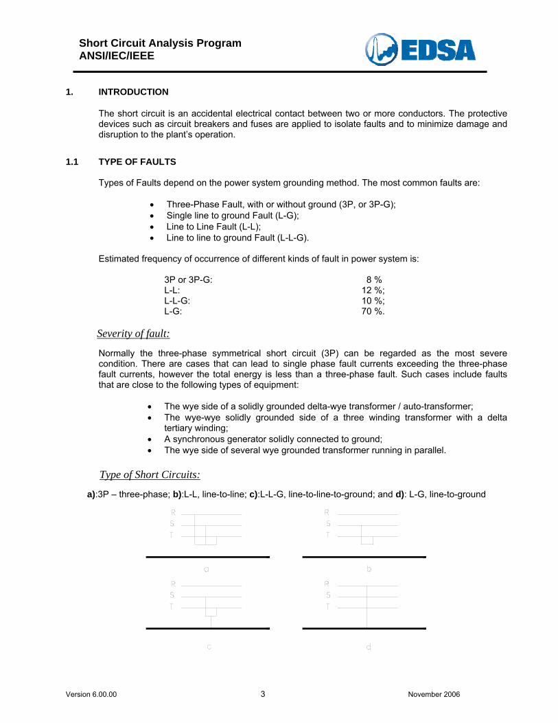
Type of Short Circuits:
a):3P – three-phase; b):L-L, line-to-line; c):L-L-G, line-to-line-to-ground; and d): L-G, line-to-ground
Short Circuit Analysis Program ANSI/IEC/IEEE
Version 6.00.00 4 November 2006
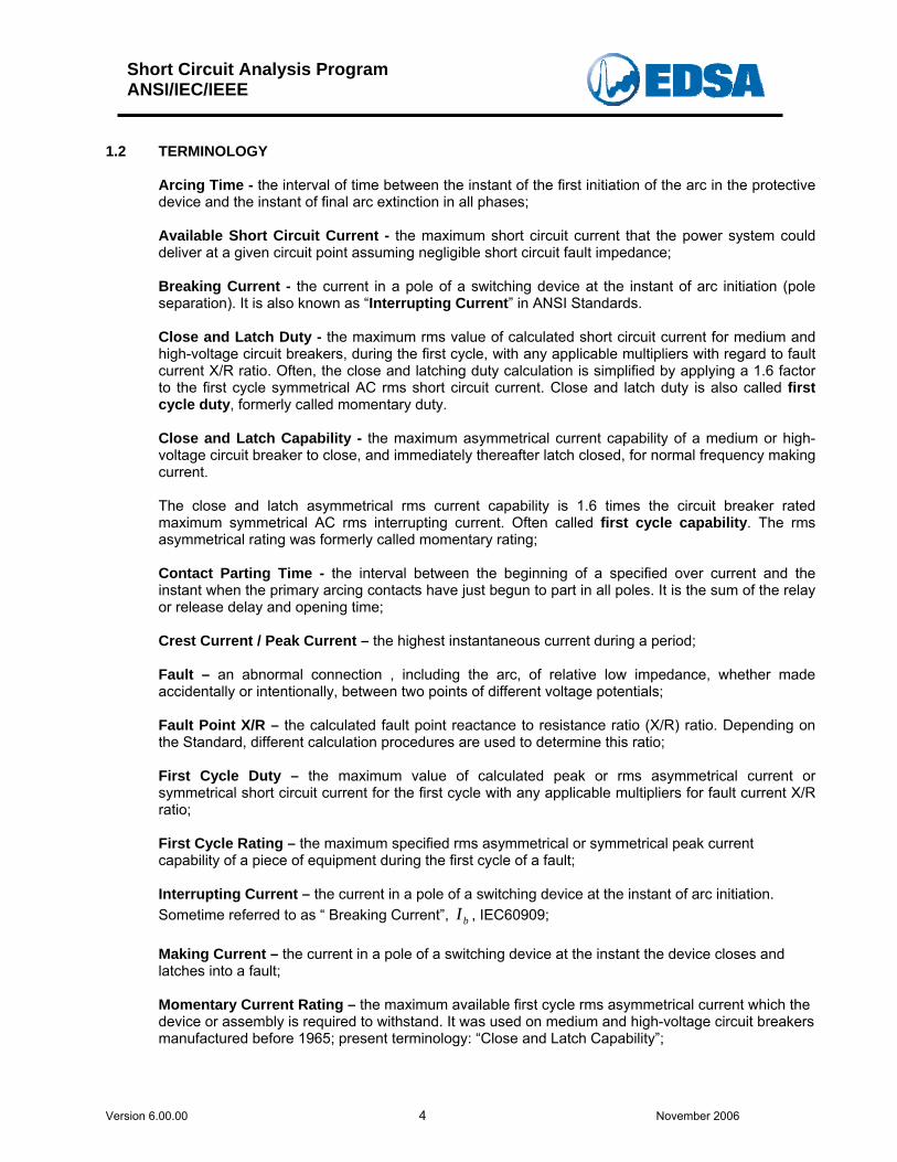
1.2 TERMINOLOGY
Arcing Time - the interval of time between the instant of the first initiation of the arc in the protective device and the instant of final arc extinction in all phases; Available Short Circuit Current - the maximum short circuit current that the power system could deliver at a given circuit point assuming negligible short circuit fault impedance; Breaking Current - the current in a pole of a switching device at the instant of arc initiation (pole separation). It is also known as “Interrupting Current” in ANSI Standards. Close and Latch Duty - the maximum rms value of calculated short circuit current for medium and high-voltage circuit breakers, during the first cycle, with any applicable multipliers with regard to fault current X/R ratio. Often, the close and latching duty calculation is simplified by applying a 1.6 factor to the first cycle symmetrical AC rms short circuit current. Close and latch duty is also called first cycle duty, formerly called momentary duty. Close and Latch Capability - the maximum asymmetrical current capability of a medium or high-voltage circuit breaker to close, and immediately thereafter latch closed, for normal frequency making current. The close and latch asymmetrical rms current capability is 1.6 times the circuit breaker rated maximum symmetrical AC rms interrupting current. Often called first cycle capability. The rms asymmetrical rating was formerly called momentary rating; Contact Parting Time - the interval between the beginning of a specified over current and the instant when the primary arcing contacts have just begun to part in all poles. It is the sum of the relay or release delay and opening time; Crest Current / Peak Current – the highest instantaneous current during a period; Fault – an abnormal connection , including the arc, of relative low impedance, whether made accidentally or intentionally, between two points of different voltage potentials; Fault Point X/R – the calculated fault point reactance to resistance ratio (X/R) ratio. Depending on the Standard, different calculation procedures are used to determine this ratio; First Cycle Duty – the maximum value of calculated peak or rms asymmetrical current or symmetrical short circuit current for the first cycle with any applicable multipliers for fault current X/R ratio; First Cycle Rating – the maximum specified rms asymmetrical or symmetrical peak current capability of a piece of equipment during the first cycle of a fault; Interrupting Current – the current in a pole of a switching device at the instant of arc initiation. Sometime referred to as “ Breaking Current”, , IEC60909; bI Making Current – the current in a pole of a switching device at the instant the device closes and latches into a fault; Momentary Current Rating – the maximum available first cycle rms asymmetrical current which the device or assembly is required to withstand. It was used on medium and high-voltage circuit breakers manufactured before 1965; present terminology: “Close and Latch Capability”;
Short Circuit Analysis Program ANSI/IEC/IEEE
Version 6.00.00 5 November 2006
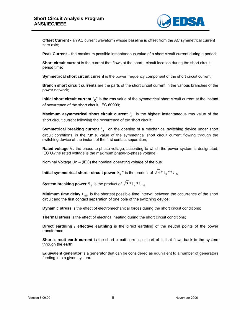
Offset Current - an AC current waveform whose baseline is offset from the AC symmetrical current zero axis; Peak Current – the maximum possible instantaneous value of a short circuit current during a period; Short circuit current is the current that flows at the short - circuit location during the short circuit period time; Symmetrical short circuit current is the power frequency component of the short circuit current; Branch short circuit currents are the parts of the short circuit current in the various branches of the power network; Initial short circuit current IK" is the rms value of the symmetrical short circuit current at the instant of occurrence of the short circuit, IEC 60909; Maximum asymmetrical short circuit current Is is the highest instantaneous rms value of the short circuit current following the occurrence of the short circuit; Symmetrical breaking current Ia , on the opening of a mechanical switching device under short circuit conditions, is the r.m.s. value of the symmetrical short circuit current flowing through the switching device at the instant of the first contact separation; Rated voltage VR the phase-to-phase voltage, according to which the power system is designated; IEC UR the rated voltage is the maximum phase-to-phase voltage; Nominal Voltage Un – (IEC) the nominal operating voltage of the bus. Initial symmetrical short - circuit power S "K is the product of 3 *I "*UK N System breaking power S is the product of B 3 *I *Ua N Minimum time delay t is the shortest possible time interval between the occurrence of the short circuit and the first contact separation of one pole of the switching device;
min
Dynamic stress is the effect of electromechanical forces during the short circuit conditions; Thermal stress is the effect of electrical heating during the short circuit conditions; Direct earthling / effective earthling is the direct earthling of the neutral points of the power transformers; Short circuit earth current is the short circuit current, or part of it, that flows back to the system through the earth; Equivalent generator is a generator that can be considered as equivalent to a number of generators feeding into a given system.
Short Circuit Analysis Program ANSI/IEC/IEEE
Version 6.00.00 6 November 2006
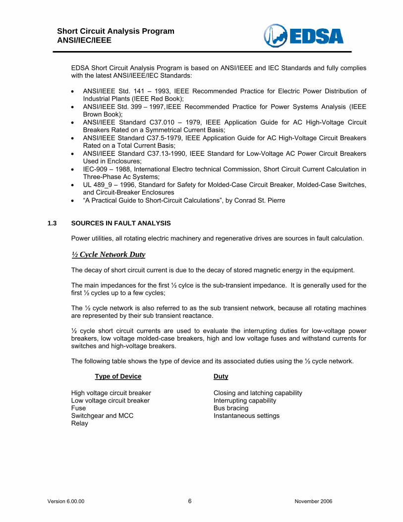
EDSA Short Circuit Analysis Program is based on ANSI/IEEE and IEC Standards and fully complies with the latest ANSI/IEEE/IEC Standards: • ANSI/IEEE Std. 141 – 1993, IEEE Recommended Practice for Electric Power Distribution of
Industrial Plants (IEEE Red Book); • ANSI/IEEE Std. 399 – 1997, IEEE Recommended Practice for Power Systems Analysis (IEEE
Brown Book); • ANSI/IEEE Standard C37.010 – 1979, IEEE Application Guide for AC High-Voltage Circuit
Breakers Rated on a Symmetrical Current Basis; • ANSI/IEEE Standard C37.5-1979, IEEE Application Guide for AC High-Voltage Circuit Breakers
Rated on a Total Current Basis; • ANSI/IEEE Standard C37.13-1990, IEEE Standard for Low-Voltage AC Power Circuit Breakers
Used in Enclosures; • IEC-909 – 1988, International Electro technical Commission, Short Circuit Current Calculation in
Three-Phase Ac Systems; • UL 489_9 – 1996, Standard for Safety for Molded-Case Circuit Breaker, Molded-Case Switches,
and Circuit-Breaker Enclosures • “A Practical Guide to Short-Circuit Calculations”, by Conrad St. Pierre
1.3 SOURCES IN FAULT ANALYSIS Power utilities, all rotating electric machinery and regenerative drives are sources in fault calculation. ½ Cycle Network Duty The decay of short circuit current is due to the decay of stored magnetic energy in the equipment. The main impedances for the first ½ cylce is the sub-transient impedance. It is generally used for the first ½ cycles up to a few cycles;
The ½ cycle network is also referred to as the sub transient network, because all rotating machines are represented by their sub transient reactance. ½ cycle short circuit currents are used to evaluate the interrupting duties for low-voltage power breakers, low voltage molded-case breakers, high and low voltage fuses and withstand currents for switches and high-voltage breakers. The following table shows the type of device and its associated duties using the ½ cycle network. Type of Device Duty High voltage circuit breaker Closing and latching capability Low voltage circuit breaker Interrupting capability Fuse Bus bracing Switchgear and MCC Instantaneous settings Relay
Short Circuit Analysis Program ANSI/IEC/IEEE
Version 6.00.00 7 November 2006
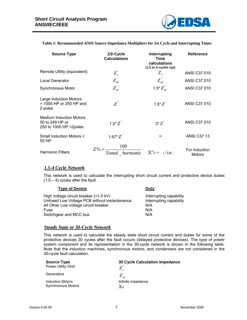
Table 1: Recommended ANSI Source Impedance Multipliers for 1st Cycle and Interrupting Times
Source Type 1/2-Cycle Calculations
Interrupting Time
calculations (1.5 to 4 cycles cpt)
Reference
Remote Utility (equivalent) "sZ sZ ANSI C37.010
Local Generator "dvZ "
dvZ ANSI C37.010
Synchronous Motor "dvZ 1.5* "
dvZ ANSI C37.010 Large Induction Motors: > 1000 HP or 250 HP and 2 poles
"Z
1.5* "Z
ANSI C37.010
Medium Induction Motors 50 to 249 HP or 250 to 1000 HP <2poles
1.2* "Z
3* "Z
ANSI C37.010
Small Induction Motors < 50 HP
1.67* "Z ∞ ANSI C37.13
Harmonic Filters harmonicTunedZ
_100% =
X”d = 1 /LRC
For Induction Motors
1.5-4 Cycle Network
This network is used to calculate the interrupting short circuit current and protective device duties (1.5 – 4) cycles after the fault.
Type of Device Duty
High voltage circuit breaker (>1.0 kV) Interrupting capability Unfused Low Voltage PCB without instantaneous Interrupting capability All Other Low voltage circuit breaker N/A Fuse N/A Switchgear and MCC bus N/A Steady State or 30-Cycle Network
This network is used to calculate the steady state short circuit current and duties for some of the protective devices 30 cycles after the fault occurs (delayed protective devices). The type of power system component and its representation in the 30-cycle network is shown in the following table. Note that the induction machines, synchronous motors, and condensers are not considered in the 30-cycle fault calculation. Source Type 30 Cycle Calculation Impedance Power Utility /Grid "
sZ
Generators 'dvZ
Induction Motors Infinite impedance Synchronous Motors Xd
Short Circuit Analysis Program ANSI/IEC/IEEE
Version 6.00.00 8 November 2006
1.4 ANSI/IEEE MULTIPLYING FACTORS (MF)
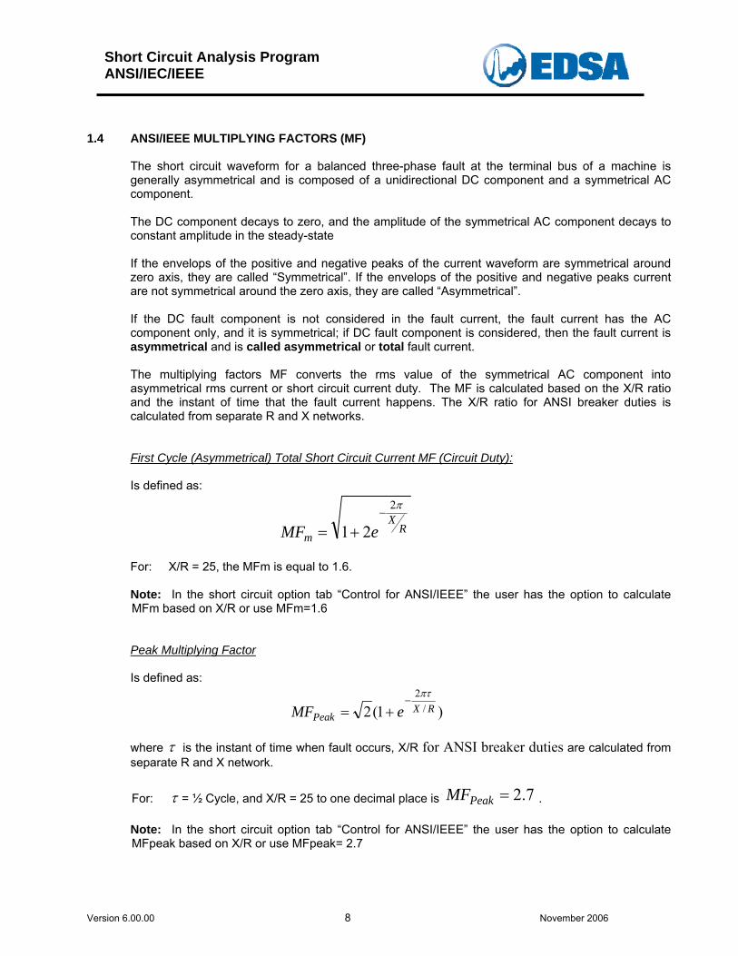
The short circuit waveform for a balanced three-phase fault at the terminal bus of a machine is generally asymmetrical and is composed of a unidirectional DC component and a symmetrical AC component. The DC component decays to zero, and the amplitude of the symmetrical AC component decays to constant amplitude in the steady-state If the envelops of the positive and negative peaks of the current waveform are symmetrical around zero axis, they are called “Symmetrical”. If the envelops of the positive and negative peaks current are not symmetrical around the zero axis, they are called “Asymmetrical”. If the DC fault component is not considered in the fault current, the fault current has the AC component only, and it is symmetrical; if DC fault component is considered, then the fault current is asymmetrical and is called asymmetrical or total fault current. The multiplying factors MF converts the rms value of the symmetrical AC component into asymmetrical rms current or short circuit current duty. The MF is calculated based on the X/R ratio and the instant of time that the fault current happens. The X/R ratio for ANSI breaker duties is calculated from separate R and X networks.
First Cycle (Asymmetrical) Total Short Circuit Current MF (Circuit Duty): Is defined as:
RX
m eMF
π2
21−
+= For: X/R = 25, the MFm is equal to 1.6. Note: In the short circuit option tab “Control for ANSI/IEEE” the user has the option to calculate MFm based on X/R or use MFm=1.6 Peak Multiplying Factor Is defined as:
)1(2 /2
RXPeak eMF
πτ−
+=
where τ is the instant of time when fault occurs, X/R for ANSI breaker duties are calculated from separate R and X network.
For: τ = ½ Cycle, and X/R = 25 to one decimal place is 7.2=PeakMF . Note: In the short circuit option tab “Control for ANSI/IEEE” the user has the option to calculate MFpeak based on X/R or use MFpeak= 2.7

Short Circuit Analysis Program ANSI/IEC/IEEE
Version 6.00.00 9 November 2006
1.5 LOCAL AND REMOTE CONTRIBUTIONS
The magnitude of the symmetrical current (AC component) from remote sources remain essentially constant “No AC Decay” (NACD) at its initial value or it may reduce with time toward a residual AC current magnitude (ACD). If the fault is close to generator, then the AC component decays (ACD). In other words, when generator is local or close to the faulted point the short circuit current decays faster. If the generator is remote from the faulted point, the ac short circuit current decay will be slow and a conservative simplification is to assume that there is no AC decay (NACD) in the symmetrical AC component. Per ANSI Standards: A generator is a LOCAL SOURCE of the short circuit current if:
• The per unit reactance external to the generator is less than 1.5 times the generator per-unit sub transient reactance on a common system base MVA.
• Its contribution to the total symmetrical rms Amperes will be greater than "*4.0d
G
XE
,
where the "d
G
XE
is the generator short circuit current for a three-phase fault at its terminal
bus. A generator is a REMOTE SOURCE of a short circuit current if:
• The per unit reactance external to the generator is equal to or exceeds 1.5 times the
generator per unit sub transient reactance on a common system base MVA.
The generator short circuit contribution may be written as:
)( "dExternal
GG
XXE
I+
=
• Its location from the fault is two or more transformations or
• Its contribution to the total symmetrical rms Amperes is less than or equal to "*4.0d
G
XE
,
where the "d
G
XE
is the generator short circuit current for a three-phase fault at its terminal bus.
The ANSI Standards provide multiplying factors (MF) based X/R ratio for three-phase faults and line-to-ground faults fed predominantly from generators and MF for faults fed predominantly from remote sources.
Short Circuit Analysis Program ANSI/IEC/IEEE
Version 6.00.00 10 November 2006
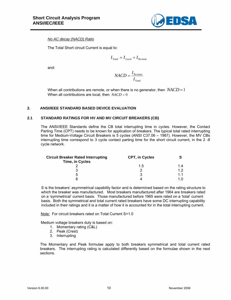
No AC decay (NACD) Ratio The Total Short circuit Current is equal to:
moteLocalTotal III Re+= and:
Total
mote
IINACD Re=
When all contributions are remote, or when there is no generator, then 1=NACDWhen all contributions are local, then 0=NACD
2. ANSI/IEEE STANDARD BASED DEVICE EVALUATION
2.1 STANDARD RATINGS FOR HV AND MV CIRCUIT BREAKERS (CB)
The ANSI/IEEE Standards define the CB total interrupting time in cycles. However, the Contact Parting Time (CPT) needs to be known for application of breakers. The typical total rated interrupting time for Medium-Voltage Circuit Breakers is 5 cycles (ANSI C37.06 – 1987). However, the MV CBs interrupting time correspond to 3 cycle contact parting time for the short circuit current, in the 2 -8 cycle network.
Circuit Breaker Rated Interrupting Time, in Cycles
CPT, in Cycles S
2 1.5 1.4 3 2 1.2 5 3 1.1 8 4 1.0
S is the breakers’ asymmetrical capability factor and is determined based on the rating structure to which the breaker was manufactured. Most breakers manufactured after 1964 are breakers rated on a ‘symmetrical’ current basis. Those manufactured before 1965 were rated on a ‘total’ current basis. Both the symmetrical and total current rated breakers have some DC interrupting capability included in their ratings and it is a matter of how it is accounted for in the total interrupting current. Note: For circuit breakers rated on Total Current S=1.0 Medium voltage breakers duty is based on:
1. Momentary rating (C&L) 2. Peak (Crest) 3. Interrupting
The Momentary and Peak formulae apply to both breakers symmetrical and total current rated breakers. The interrupting rating is calculated differently based on the formulae shown in the next sections.
Short Circuit Analysis Program ANSI/IEC/IEEE
Version 6.00.00 11 November 2006
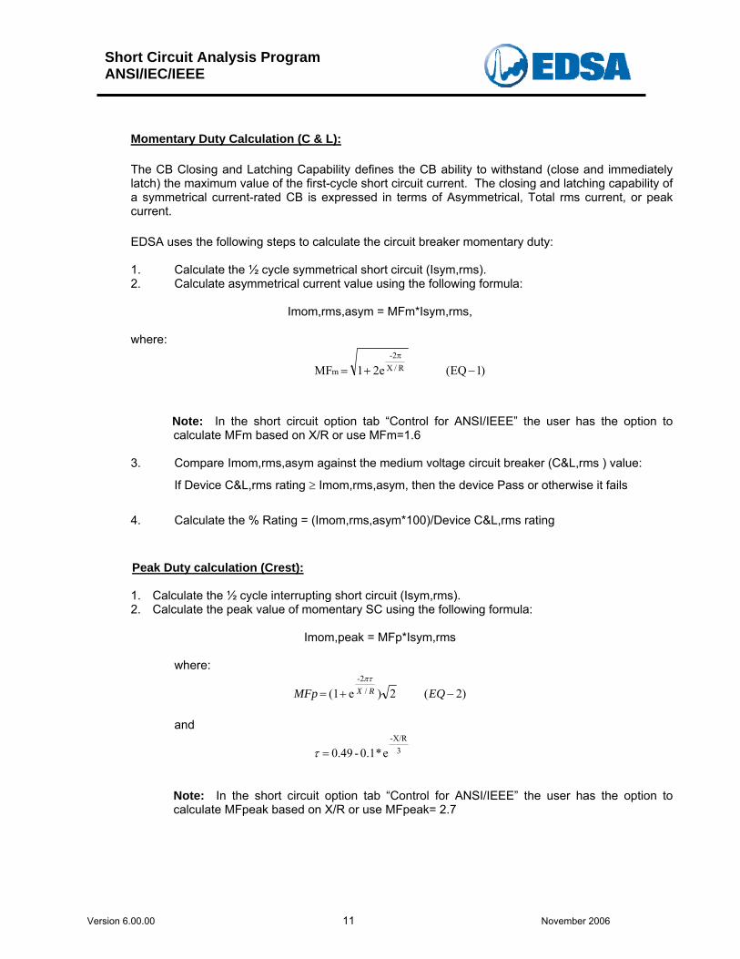
Momentary Duty Calculation (C & L):
The CB Closing and Latching Capability defines the CB ability to withstand (close and immediately latch) the maximum value of the first-cycle short circuit current. The closing and latching capability of a symmetrical current-rated CB is expressed in terms of Asymmetrical, Total rms current, or peak current.
EDSA uses the following steps to calculate the circuit breaker momentary duty:
1. Calculate the ½ cycle symmetrical short circuit (Isym,rms). 2. Calculate asymmetrical current value using the following formula:
Imom,rms,asym = MFm*Isym,rms,
where:
)1EQ(2e1 MF R/X-2
m −+=π
Note: In the short circuit option tab “Control for ANSI/IEEE” the user has the option to calculate MFm based on X/R or use MFm=1.6
3. Compare Imom,rms,asym against the medium voltage circuit breaker (C&L,rms ) value:
If Device C&L,rms rating ≥ Imom,rms,asym, then the device Pass or otherwise it fails
4. Calculate the % Rating = (Imom,rms,asym*100)/Device C&L,rms rating
Peak Duty calculation (Crest):
1. Calculate the ½ cycle interrupting short circuit (Isym,rms). 2. Calculate the peak value of momentary SC using the following formula:
Imom,peak = MFp*Isym,rms
where:
)2(2)e(1 /-2
−+= EQMFp RXπτ
and
3-X/R
e*0.1-0.49 =τ
Note: In the short circuit option tab “Control for ANSI/IEEE” the user has the option to calculate MFpeak based on X/R or use MFpeak= 2.7
Short Circuit Analysis Program ANSI/IEC/IEEE
Version 6.00.00 12 November 2006
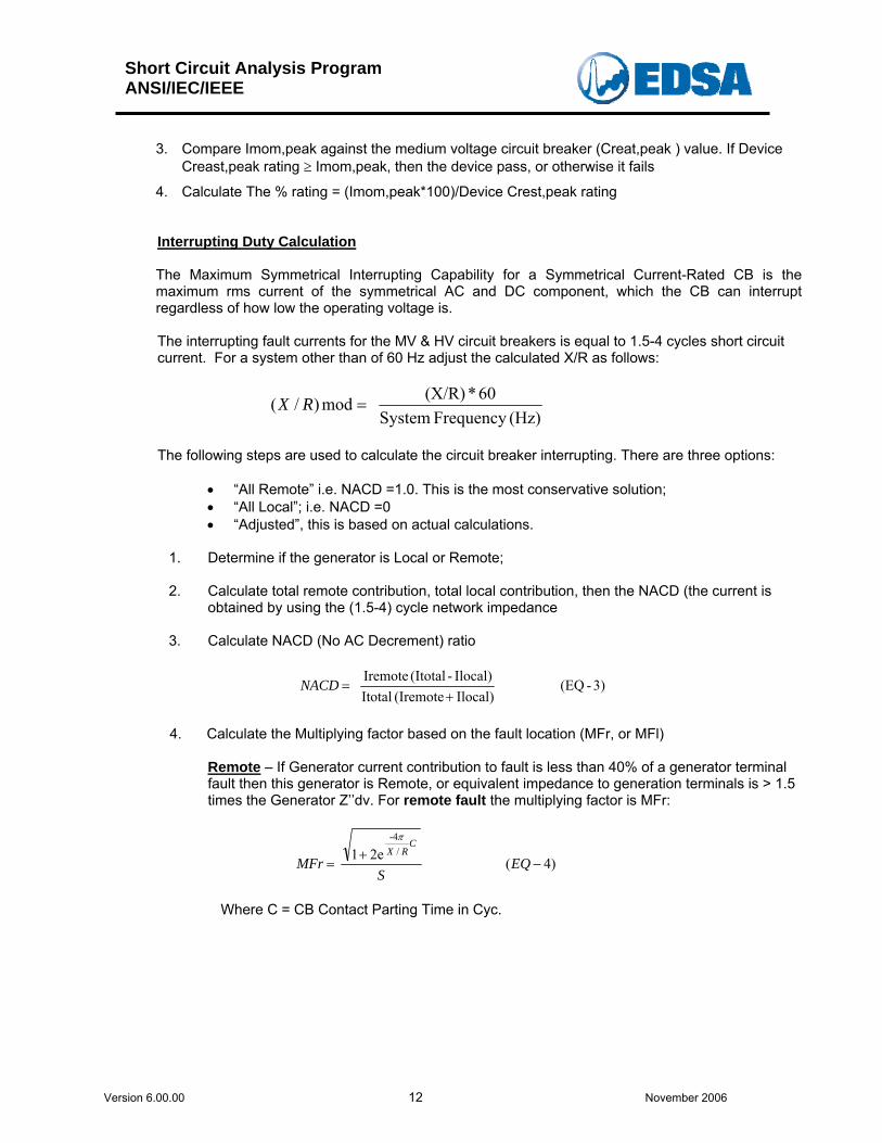
3. Compare Imom,peak against the medium voltage circuit breaker (Creat,peak ) value. If Device
Creast,peak rating ≥ Imom,peak, then the device pass, or otherwise it fails
4. Calculate The % rating = (Imom,peak*100)/Device Crest,peak rating
Interrupting Duty Calculation
The Maximum Symmetrical Interrupting Capability for a Symmetrical Current-Rated CB is the maximum rms current of the symmetrical AC and DC component, which the CB can interrupt regardless of how low the operating voltage is.
The interrupting fault currents for the MV & HV circuit breakers is equal to 1.5-4 cycles short circuit current. For a system other than of 60 Hz adjust the calculated X/R as follows:
(Hz)Frequency System
60*(X/R) mod)/( =RX
The following steps are used to calculate the circuit breaker interrupting. There are three options:
• “All Remote” i.e. NACD =1.0. This is the most conservative solution; • “All Local”; i.e. NACD =0 • “Adjusted”, this is based on actual calculations.
1. Determine if the generator is Local or Remote; 2. Calculate total remote contribution, total local contribution, then the NACD (the current is
obtained by using the (1.5-4) cycle network impedance
3. Calculate NACD (No AC Decrement) ratio
3)-(EQ Ilocal)(Iremote ItotalIlocal)-(Itotal Iremote
+=NACD
4. Calculate the Multiplying factor based on the fault location (MFr, or MFl)
Remote – If Generator current contribution to fault is less than 40% of a generator terminal fault then this generator is Remote, or equivalent impedance to generation terminals is > 1.5 times the Generator Z’’dv. For remote fault the multiplying factor is MFr:
)4(2e1 /
-4
−+
= EQS
MFrC
RXπ
Where C = CB Contact Parting Time in Cyc.
Short Circuit Analysis Program ANSI/IEC/IEEE
Version 6.00.00 13 November 2006
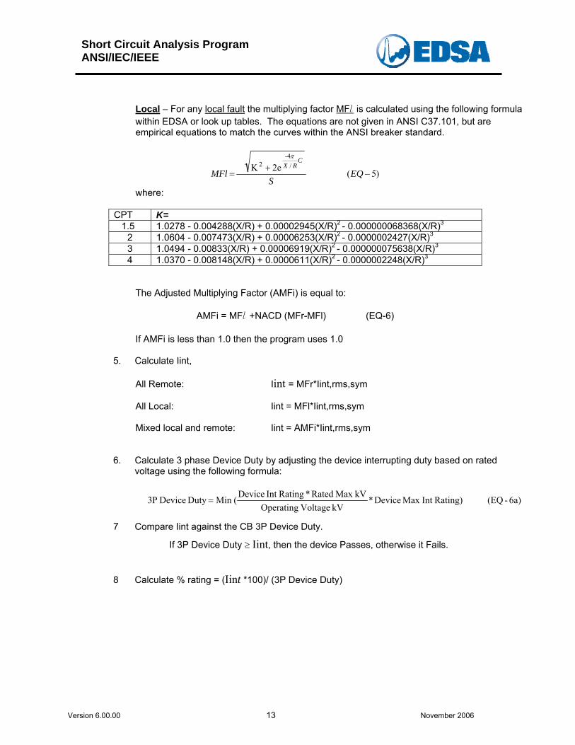
Local – For any local fault the multiplying factor MFl is calculated using the following formula within EDSA or look up tables. The equations are not given in ANSI C37.101, but are empirical equations to match the curves within the ANSI breaker standard.
)5(2eK /
-42
−+
= EQS
MFlC
RXπ
where:
CPT K= 1.5 1.0278 - 0.004288(X/R) + 0.00002945(X/R)2 - 0.000000068368(X/R)3
2 1.0604 - 0.007473(X/R) + 0.00006253(X/R)2 - 0.0000002427(X/R)3 3 1.0494 - 0.00833(X/R) + 0.00006919(X/R)2 - 0.000000075638(X/R)3 4 1.0370 - 0.008148(X/R) + 0.0000611(X/R)2 - 0.0000002248(X/R)3
The Adjusted Multiplying Factor (AMFi) is equal to:
AMFi = MFl +NACD (MFr-MFl) (EQ-6) If AMFi is less than 1.0 then the program uses 1.0
5. Calculate Iint,
All Remote: Iint = MFr*Iint,rms,sym
All Local: Iint = MFl*Iint,rms,sym
Mixed local and remote: Iint = AMFi*Iint,rms,sym
6. Calculate 3 phase Device Duty by adjusting the device interrupting duty based on rated voltage using the following formula:
6a)-(EQRating)Int Max Device*kV Voltage Operating
kVMax Rated * RatingInt Device(Min Duty Device P3 =
7 Compare Iint against the CB 3P Device Duty.
If 3P Device Duty ≥ Iint, then the device Passes, otherwise it Fails.
8 Calculate % rating = (Iint *100)/ (3P Device Duty)
Short Circuit Analysis Program ANSI/IEC/IEEE
Version 6.00.00 14 November 2006
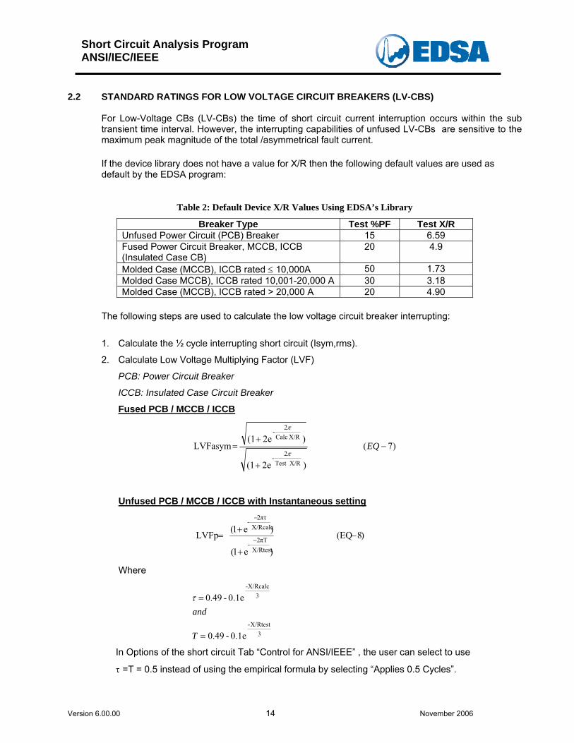
2.2 STANDARD RATINGS FOR LOW VOLTAGE CIRCUIT BREAKERS (LV-CBS)
For Low-Voltage CBs (LV-CBs) the time of short circuit current interruption occurs within the sub transient time interval. However, the interrupting capabilities of unfused LV-CBs are sensitive to the maximum peak magnitude of the total /asymmetrical fault current. If the device library does not have a value for X/R then the following default values are used as default by the EDSA program:
Table 2: Default Device X/R Values Using EDSA’s Library
Breaker Type Test %PF Test X/R Unfused Power Circuit (PCB) Breaker 15 6.59 Fused Power Circuit Breaker, MCCB, ICCB (Insulated Case CB)
20 4.9
Molded Case (MCCB), ICCB rated ≤ 10,000A 50 1.73 Molded Case MCCB), ICCB rated 10,001-20,000 A 30 3.18 Molded Case (MCCB), ICCB rated > 20,000 A 20 4.90
The following steps are used to calculate the low voltage circuit breaker interrupting:
1. Calculate the ½ cycle interrupting short circuit (Isym,rms).
2. Calculate Low Voltage Multiplying Factor (LVF)
PCB: Power Circuit Breaker
ICCB: Insulated Case Circuit Breaker
Fused PCB / MCCB / ICCB
)7(
)e2(1
)e2(1 LVFasym
X/RTest 2-
X/R Calc2-
−
+
+= EQ
π
π
Unfused PCB / MCCB / ICCB with Instantaneous setting
)8(EQ
)e1(
)e1( LVFp X/Rtest
πT2-
X/Rcalcπτ2
-
−
+
+= −
−
Where
3X/Rtest-
3-X/Rcalc
0.1e - 0.49
0.1e - 0.49
=
=
T
andτ
In Options of the short circuit Tab “Control for ANSI/IEEE” , the user can select to use
τ =T = 0.5 instead of using the empirical formula by selecting “Applies 0.5 Cycles”.
Short Circuit Analysis Program ANSI/IEC/IEEE
Version 6.00.00 15 November 2006
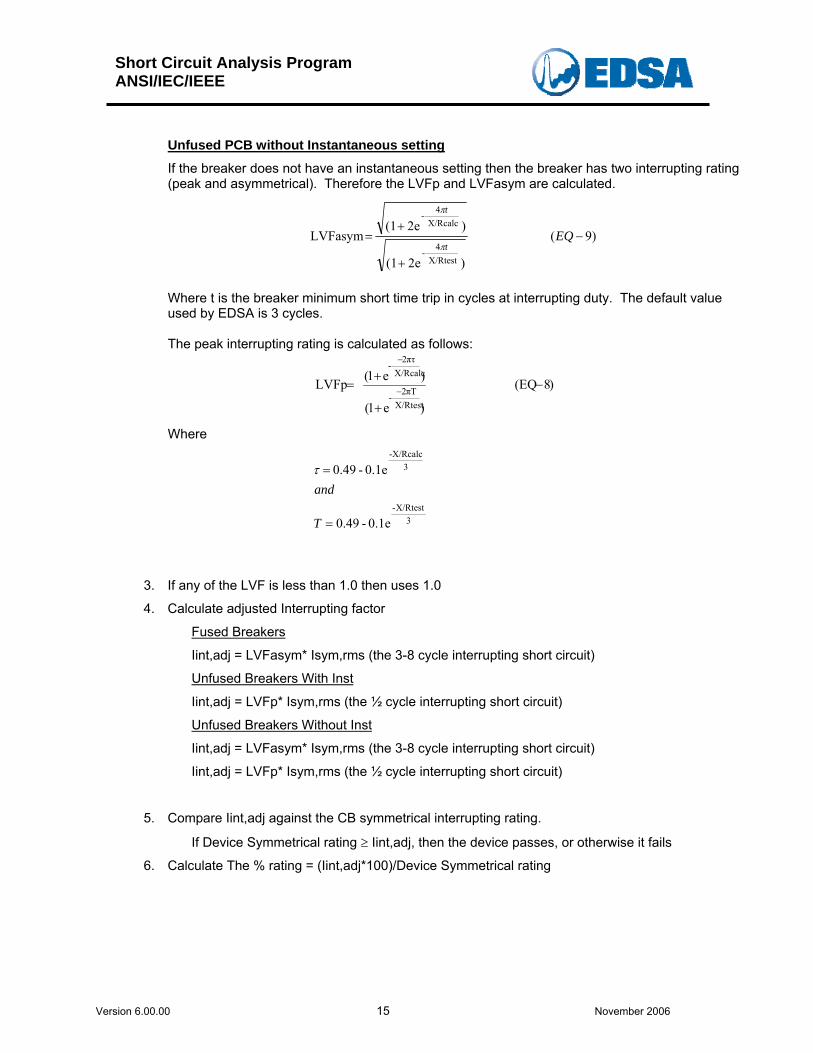
Unfused PCB without Instantaneous setting
If the breaker does not have an instantaneous setting then the breaker has two interrupting rating (peak and asymmetrical). Therefore the LVFp and LVFasym are calculated.
)9(
)e2(1
)e2(1 LVFasym
X/Rtest 4-
X/Rcalc 4-
−
+
+= EQ
t
t
π
π
Where t is the breaker minimum short time trip in cycles at interrupting duty. The default value used by EDSA is 3 cycles. The peak interrupting rating is calculated as follows:
)8(EQ
)e1(
)e1( LVFp X/Rtest
πT2-
X/Rcalcπτ2
-
−
+
+= −
−
Where
3
X/Rtest-
3-X/Rcalc
0.1e - 0.49
0.1e - 0.49
=
=
T
andτ
3. If any of the LVF is less than 1.0 then uses 1.0
4. Calculate adjusted Interrupting factor
Fused Breakers
Iint,adj = LVFasym* Isym,rms (the 3-8 cycle interrupting short circuit)
Unfused Breakers With Inst
Iint,adj = LVFp* Isym,rms (the ½ cycle interrupting short circuit)
Unfused Breakers Without Inst
Iint,adj = LVFasym* Isym,rms (the 3-8 cycle interrupting short circuit)
Iint,adj = LVFp* Isym,rms (the ½ cycle interrupting short circuit)
5. Compare Iint,adj against the CB symmetrical interrupting rating.
If Device Symmetrical rating ≥ Iint,adj, then the device passes, or otherwise it fails
6. Calculate The % rating = (Iint,adj*100)/Device Symmetrical rating
Short Circuit Analysis Program ANSI/IEC/IEEE
Version 6.00.00 16 November 2006
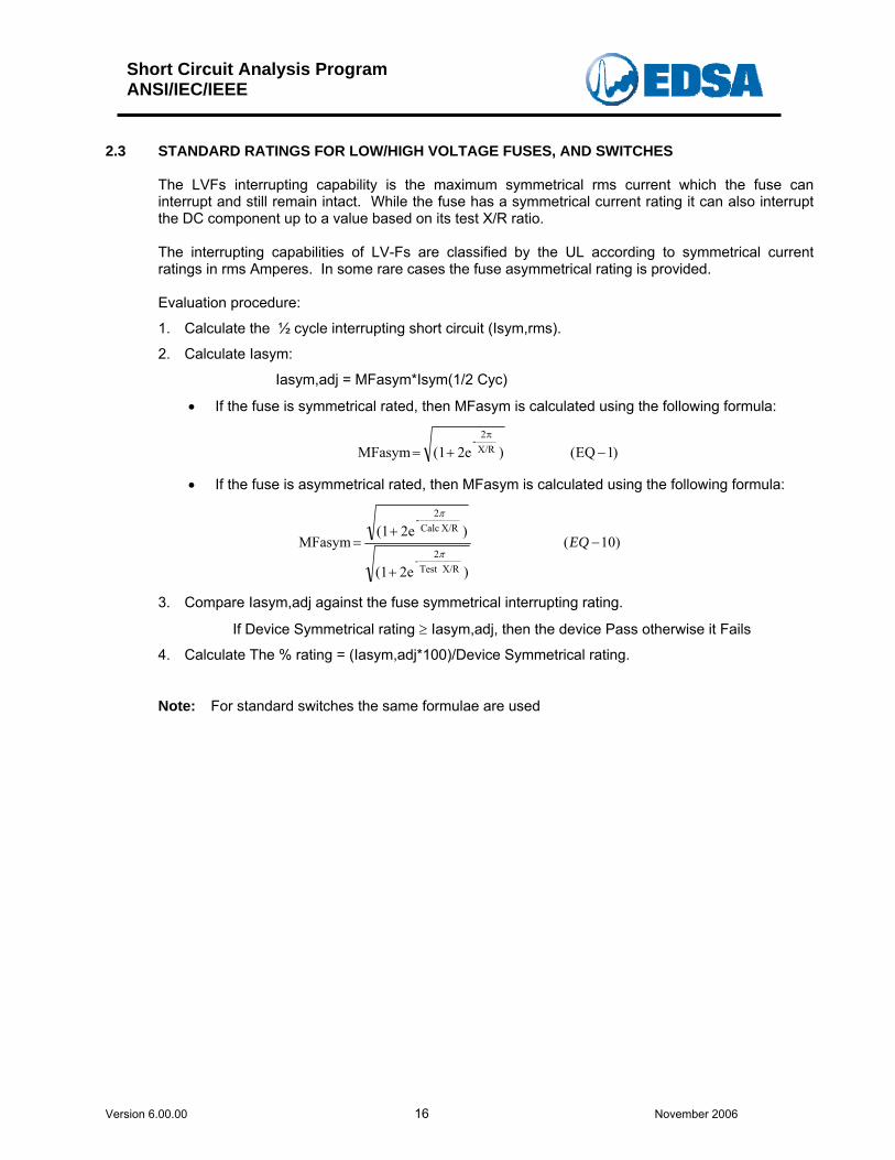
2.3 STANDARD RATINGS FOR LOW/HIGH VOLTAGE FUSES, AND SWITCHES
The LVFs interrupting capability is the maximum symmetrical rms current which the fuse can interrupt and still remain intact. While the fuse has a symmetrical current rating it can also interrupt the DC component up to a value based on its test X/R ratio. The interrupting capabilities of LV-Fs are classified by the UL according to symmetrical current ratings in rms Amperes. In some rare cases the fuse asymmetrical rating is provided. Evaluation procedure:
1. Calculate the ½ cycle interrupting short circuit (Isym,rms).
2. Calculate Iasym:
Iasym,adj = MFasym*Isym(1/2 Cyc)
• If the fuse is symmetrical rated, then MFasym is calculated using the following formula:
)1EQ()e2(1 MFasym X/R2-
−+=π
• If the fuse is asymmetrical rated, then MFasym is calculated using the following formula:
)10(
)e2(1
)e2(1 MFasym
X/RTest 2-
X/R Calc2-
−
+
+= EQ
π
π
3. Compare Iasym,adj against the fuse symmetrical interrupting rating.
If Device Symmetrical rating ≥ Iasym,adj, then the device Pass otherwise it Fails
4. Calculate The % rating = (Iasym,adj*100)/Device Symmetrical rating.
Note: For standard switches the same formulae are used
Short Circuit Analysis Program ANSI/IEC/IEEE
Version 6.00.00 17 November 2006
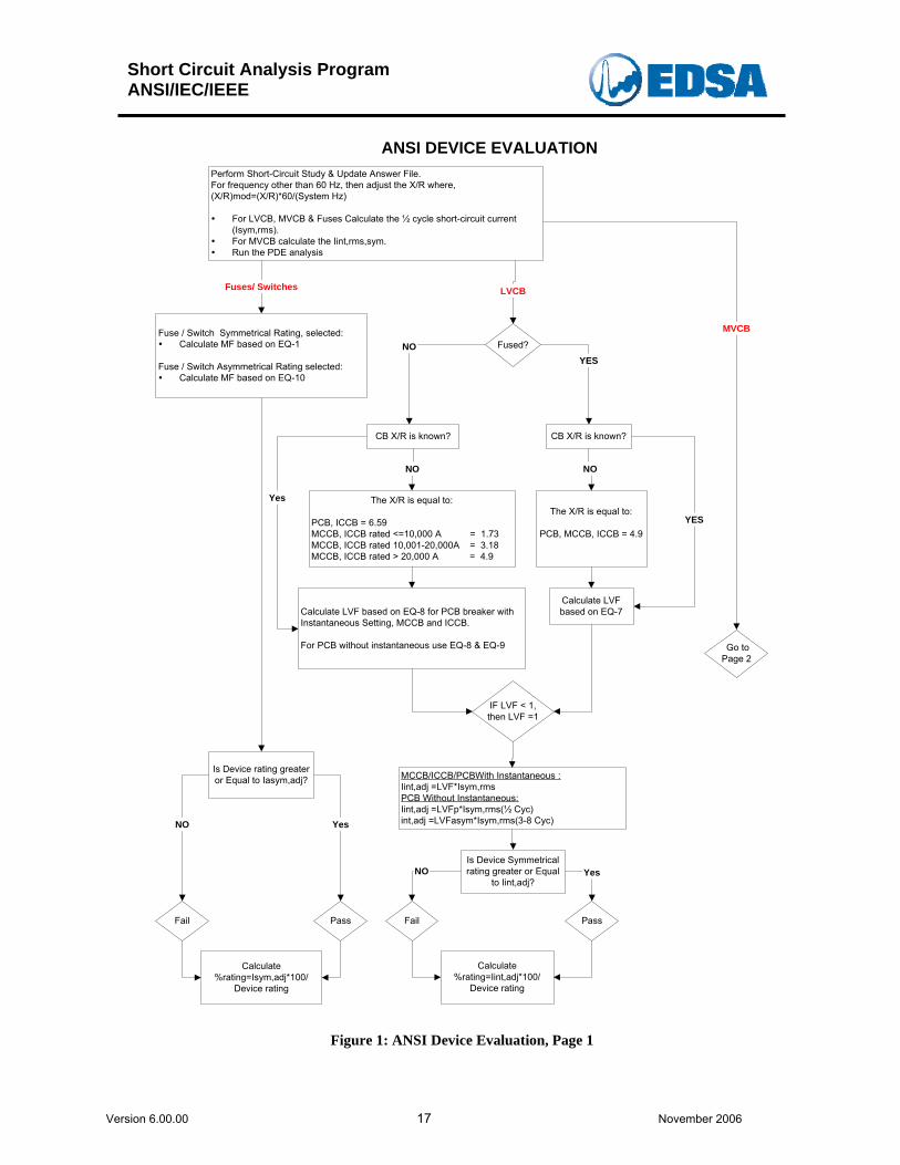
ANSI DEVICE EVALUATIONPerform Short-Circuit Study & Update Answer File.For frequency other than 60 Hz, then adjust the X/R where,(X/R)mod=(X/R)*60/(System Hz)
For LVCB, MVCB & Fuses Calculate the ½ cycle short-circuit current(Isym,rms).For MVCB calculate the Iint,rms,sym.Run the PDE analysis
Fused?
Fuses/ Switches LVCB
Yes
IF LVF < 1,then LVF =1
MCCB/ICCB/PCBWith Instantaneous :Iint,adj =LVF*Isym,rmsPCB Without Instantaneous:Iint,adj =LVFp*Isym,rms(½ Cyc)int,adj =LVFasym*Isym,rms(3-8 Cyc)
CB X/R is known?
The X/R is equal to:
PCB, MCCB, ICCB = 4.9
Calculate LVF based on EQ-8 for PCB breaker withInstantaneous Setting, MCCB and ICCB.
For PCB without instantaneous use EQ-8 & EQ-9
Calculate LVFbased on EQ-7
NOYES
NO
YES
CB X/R is known?
NO
Is Device Symmetricalrating greater or Equal
to Iint,adj?
PassFail
YesNO
Calculate%rating=Iint,adj*100/
Device rating
Is Device rating greateror Equal to Iasym,adj?
PassFail
YesNO
Calculate%rating=Isym,adj*100/
Device rating
MVCBFuse / Switch Symmetrical Rating, selected:Calculate MF based on EQ-1
Fuse / Switch Asymmetrical Rating selected:Calculate MF based on EQ-10
The X/R is equal to:
PCB, ICCB = 6.59MCCB, ICCB rated <=10,000 A = 1.73MCCB, ICCB rated 10,001-20,000A = 3.18MCCB, ICCB rated > 20,000 A = 4.9
Go toPage 2
Figure 1: ANSI Device Evaluation, Page 1

Short Circuit Analysis Program ANSI/IEC/IEEE
Version 6.00.00 18 November 2006
ANSI DEVICE EVALUATIONPage 2MVCB From
Page 1
CalculateImom,asym=MFm*Isym,rms
Calculate MFp using EQ-2
Calculation Based on Generation:All RemoteAll LocalNACD
CalculateMFr using EQ-4Iint=MFr*Iint,rms,sym
CalculateMFl using EQ-5Iint=MFl*Iint,rms,sym
Calculate:NACD using EQ-3MFr using EQ-4MFl using EQ-5AMFi = using EQ-6.If AMFl less than 1 use 1.0Iint = AMFi*Iint,rms,sym/S
Is Device peak (crest)rating greater or Equal to
Imom,peak?
PassFail
YesNO
Calculate%rating=Imom,peak*100/device peak (crest) rating
Calculate 3 phase deviceduty using EQ-6a
Is Device Int rating greateror Equal to calculated Iint?
PassFail
YesNO
Calculate %rating=Iint*100/3P device Int rating
Is Device C&L,rms ratinggreater or Equal toImom,rms,asym?
PassFail
YesNO
Calculate%rating=Imom,rms,asym*100/
device C&L,rms rating
Calculate:Total Remote ContributionTotal Local contributionTotal Contribution (Iint,rms,sym)NACD using (EQ-3)If NACD=0 then all contribution are LocalIf NACD=1 then all contribution are Remote
ALL Remote
All Local
NACD
In the short circuit option tab“Control for ANSI/IEEE” the userhas selected the fixed MF factor
NO
NO
CalculateImom,peak=MFp*Isym,rms
Calculate MFm using EQ-1
YES
MFp = 2.7
YES
MFm = 1.6
Peak Duty(Crest)
MomentaryDuty (C&L)
Peak Duty(Crest)
MomentaryDuty (C&L)
Interrupting Duty
Figure 2: ANSI Device Evaluation, Page 2
Short Circuit Analysis Program ANSI/IEC/IEEE
Version 6.00.00 19 November 2006
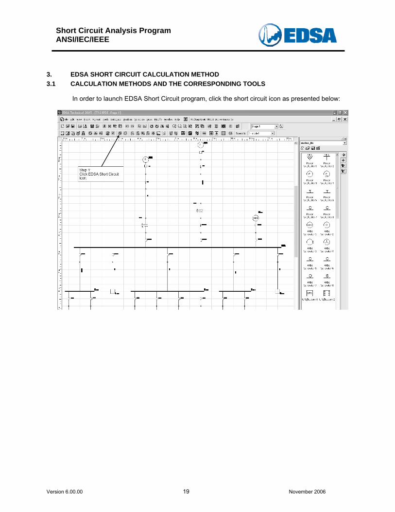
3. EDSA SHORT CIRCUIT CALCULATION METHOD 3.1 CALCULATION METHODS AND THE CORRESPONDING TOOLS
In order to launch EDSA Short Circuit program, click the short circuit icon as presented below:
Short Circuit Analysis Program ANSI/IEC/IEEE
Version 6.00.00 20 November 2006
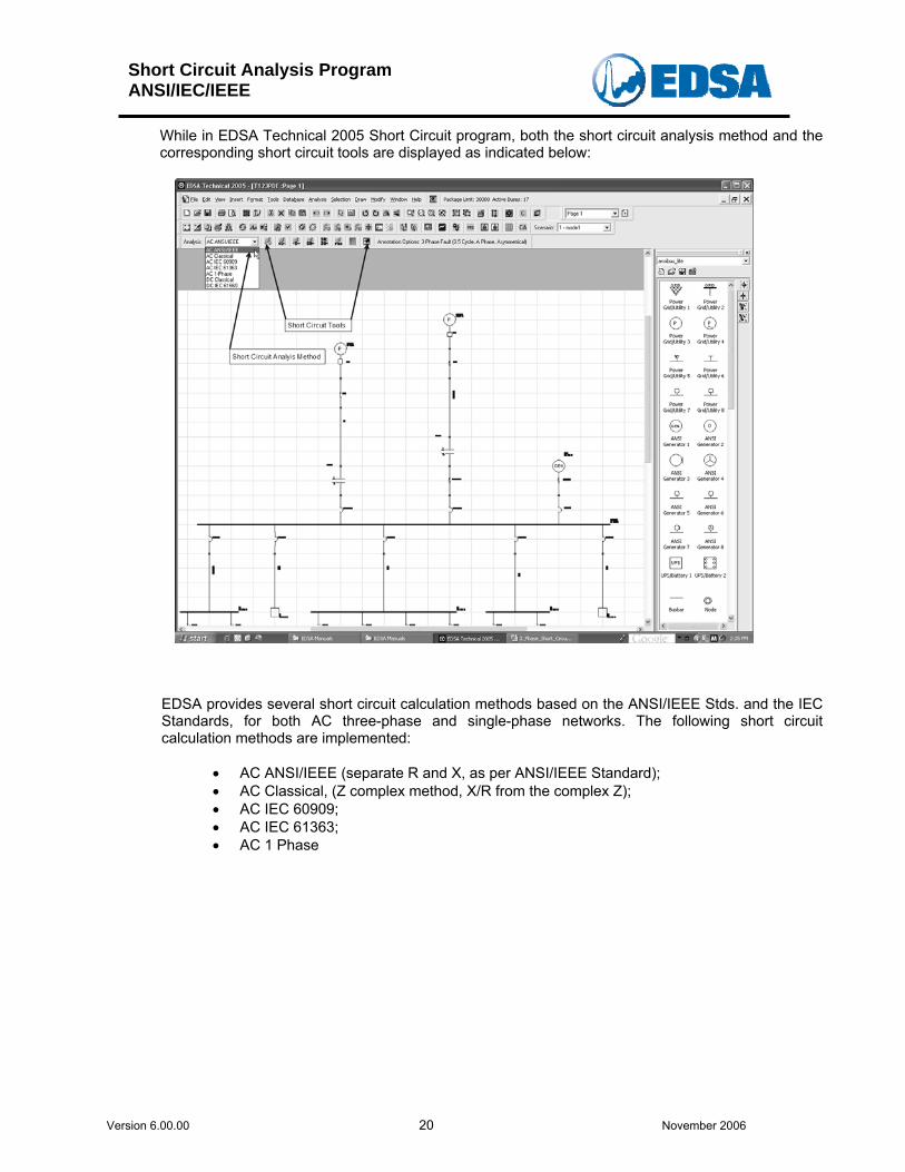
While in EDSA Technical 2005 Short Circuit program, both the short circuit analysis method and the corresponding short circuit tools are displayed as indicated below:
EDSA provides several short circuit calculation methods based on the ANSI/IEEE Stds. and the IEC Standards, for both AC three-phase and single-phase networks. The following short circuit calculation methods are implemented:
• AC ANSI/IEEE (separate R and X, as per ANSI/IEEE Standard); • AC Classical, (Z complex method, X/R from the complex Z); • AC IEC 60909; • AC IEC 61363; • AC 1 Phase
Short Circuit Analysis Program ANSI/IEC/IEEE
Version 6.00.00 21 November 2006
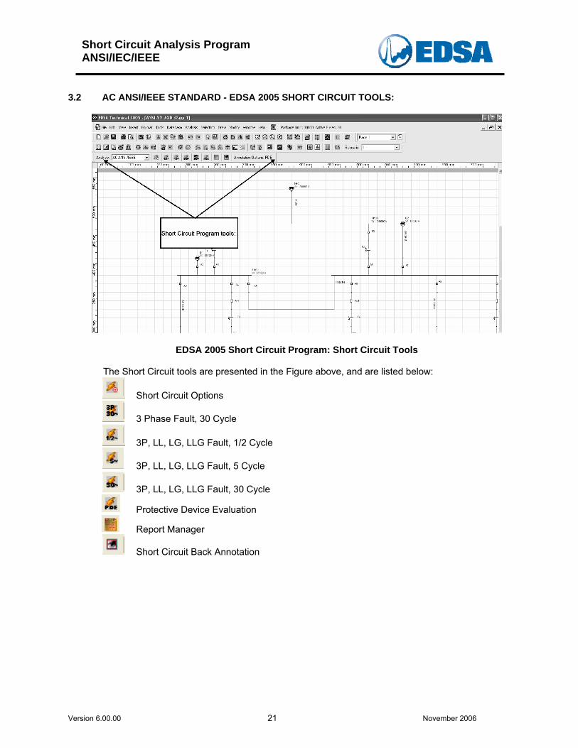
3.2 AC ANSI/IEEE STANDARD - EDSA 2005 SHORT CIRCUIT TOOLS:
EDSA 2005 Short Circuit Program: Short Circuit Tools The Short Circuit tools are presented in the Figure above, and are listed below:
Short Circuit Options
3 Phase Fault, 30 Cycle
3P, LL, LG, LLG Fault, 1/2 Cycle
3P, LL, LG, LLG Fault, 5 Cycle
3P, LL, LG, LLG Fault, 30 Cycle
Protective Device Evaluation
Report Manager
Short Circuit Back Annotation
Short Circuit Analysis Program ANSI/IEC/IEEE
Version 6.00.00 22 November 2006
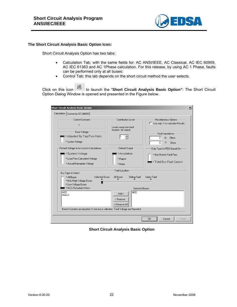
The Short Circuit Analysis Basic Option Icon:
Short Circuit Analysis Option has two tabs:
• Calculation Tab, with the same fields for: AC ANSI/IEEE, AC Classical, AC IEC 60909, AC IEC 61363 and AC 1Phase calculation. For this release, by using AC 1 Phase, faults can be performed only at all buses:
• Control Tab: this tab depends on the short circuit method the user selects.
Click on this icon to launch the “Short Circuit Analysis Basic Option”: The Short Circuit Option Dialog Window is opened and presented in the Figure below.
Short Circuit Analysis Basic Option
Short Circuit Analysis Program ANSI/IEC/IEEE
Version 6.00.00 23 November 2006
Calculation Tab allows the user to select the followings:
• Base voltage: Adjusted by tap/turn ratio if power transformer running off nominal taps, or system voltage;
• Prefault voltage to be used in fault calculation: system voltage, load flow calculated voltage or actual / name plate voltage;
• Default output: Annotation, report or none; • Contribution level: levels away from the fault location for output (to the screen or fault
report; when selecting contribution levels of n buses away, depending on the number of faulted buses, the calculated results are displayed on the one-line diagram and printed in the output report;
• Fault impedance, only if the fault is at one bus only; • Fault location: selected buses, all buses, sliding fault or series fault; (Sliding and series
fault does not apply to IEC61363 or AC 1phase calculation) • Miscellaneous options: use only X to calculate the faults, and apply phase shift; • Duty type for PDE based on: maximum branch fault flow or total bus fault current. • Use the Schedule option to run schedules.
Fault Location
• Fault at one or more buses in the same run; • Fault at all system buses, when the buses are faulted individually, not simultaneously.
Depending on the specified fault type, the program will place a three-phase, line-to-ground, line-to-line, and line-to-line-to-ground fault at each bus which is faulted for short circuit studies.
Selection of One Bus:
The Bus can be selected:
• Graphically on the drawing, by a simple click on the desired bus, or; • Highlight the bus ID in the Short Circuit Option and then click on the “Add” button; the
selected bus will be transferred to the “Selected Buses” list. To remove a bus from the “Selected Buses” list highlight the bus ID and click on “Remove” button. The highlighted bus will be transferred to the “All Buses“ list.
If One Bus is selected, then any fault type at that bus is calculated, branch contribution to that fault, bus post-fault voltage and fault summary are generated.
Selecting More Than One Bus:
• Graphically on the drawing space: click onto the desired first bus, then hold down the
“shift key”; while the “shift key” is being held down, select each bus individually; • Menu Driven: highlight the desired bus ID in the Short Circuit Option and then click on
the Add; the selected buses will be transferred to the “Selected Buses” list. To remove a bus or several buses from the Selected Buses List highlight the bus ID and click on Remove button. The highlighted bus/buses will be transferred to the “All Buses” List.

Short Circuit Analysis Program ANSI/IEC/IEEE
Version 6.00.00 24 November 2006
Notes:
• Faults at more than one bus, are faulted individually in turn, not simultaneously. Depending on the specified fault type, the program will place a three-phase, line-to-ground, line-to-line, and line-to-line-to-ground fault at each selected bus which is faulted for short circuit studies;
• On the drawing are displayed only the bus fault current value: Symmetrical rms, DC rms, Asymmetrical rms, IPeak instantaneous value, as per user selection in the Short Circuit Back Annotation.
Selecting All Buses:
Fault at all buses can be selected from the “Short Circuit Analysis Basic Option only, by selecting “All Buses” option.
• Faults at “All Buses”, are faulted individually, not simultaneously. Depending on the specified fault type, the program will place a three-phase, line-to-ground, line-to-line, and line-to-line-to-ground fault at all buses which are faulted for short circuit studies;
• On the drawing are displayed: Symmetrical rms, DC rms, Asymmetrical rms, IPeak instantaneous value, as per user selection in the Short Circuit Back Annotation.
• All buses are colored in “Red”. The Short Circuit Report will provide:
• Bus Fault Current (3P, L-L, L-L-G, L-G, depending on the user selection); • Branch currents (3P, L-L, L-L-G, L-G, depending on the user selection); • Short Circuit multiplying Factors; • Fault Summary;
Short Circuit Analysis Program ANSI/IEC/IEEE
Version 6.00.00 25 November 2006
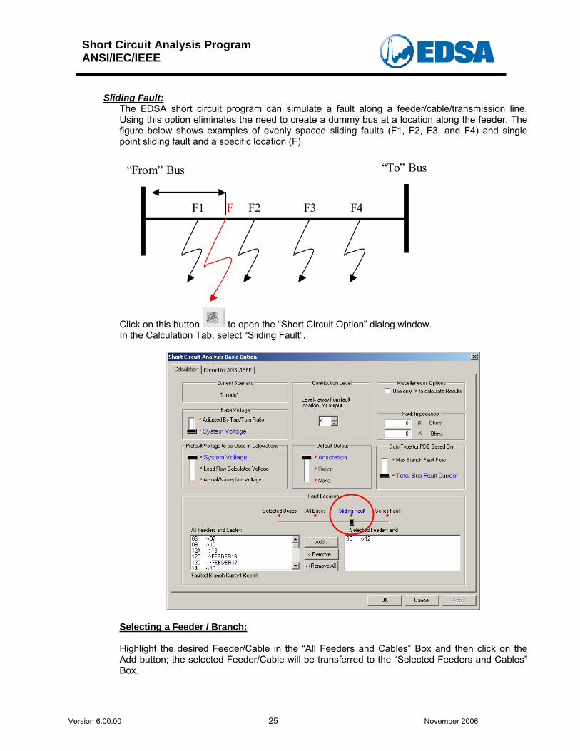
Sliding Fault:
The EDSA short circuit program can simulate a fault along a feeder/cable/transmission line. Using this option eliminates the need to create a dummy bus at a location along the feeder. The figure below shows examples of evenly spaced sliding faults (F1, F2, F3, and F4) and single point sliding fault and a specific location (F).
F1 F2 F3 F4F
“To” Bus “From” Bus
Click on this button to open the “Short Circuit Option” dialog window. In the Calculation Tab, select “Sliding Fault”.
Selecting a Feeder / Branch: Highlight the desired Feeder/Cable in the “All Feeders and Cables” Box and then click on the Add button; the selected Feeder/Cable will be transferred to the “Selected Feeders and Cables” Box.
Short Circuit Analysis Program ANSI/IEC/IEEE
Version 6.00.00 26 November 2006
To remove a Feeder/Cable from the “Selected Feeders and Cables” box, highlight the Feeder/Cable and click on Remove button. The highlighted Feeder/Cable will be transferred to the “All Feeders / and Cables Box / List. In this release, only one Feeder/Cable can be selected for Sliding fault calculation at a time. Select a feeder “3C – 12”, and then press on the “OK” button; the Sliding Fault Report Manager is displayed as presented below: Note: Sliding fault does not apply to IEC61363 and AC 1 Phase calculation.
Short Circuit Analysis Program ANSI/IEC/IEEE
Version 6.00.00 27 November 2006
Sliding Fault: Report Manager
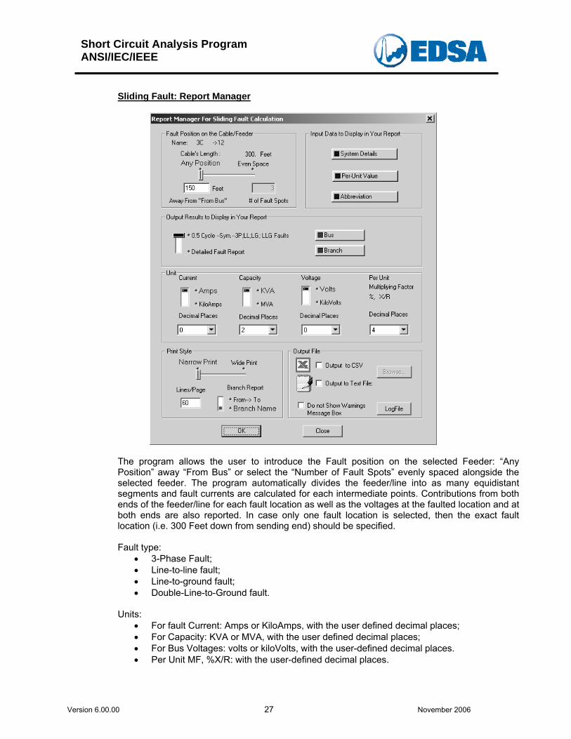
The program allows the user to introduce the Fault position on the selected Feeder: “Any Position” away “From Bus” or select the “Number of Fault Spots” evenly spaced alongside the selected feeder. The program automatically divides the feeder/line into as many equidistant segments and fault currents are calculated for each intermediate points. Contributions from both ends of the feeder/line for each fault location as well as the voltages at the faulted location and at both ends are also reported. In case only one fault location is selected, then the exact fault location (i.e. 300 Feet down from sending end) should be specified. Fault type:
• 3-Phase Fault; • Line-to-line fault; • Line-to-ground fault; • Double-Line-to-Ground fault.
Units:
• For fault Current: Amps or KiloAmps, with the user defined decimal places; • For Capacity: KVA or MVA, with the user defined decimal places; • For Bus Voltages: volts or kiloVolts, with the user-defined decimal places. • Per Unit MF, %X/R: with the user-defined decimal places.
Short Circuit Analysis Program ANSI/IEC/IEEE
Version 6.00.00 28 November 2006
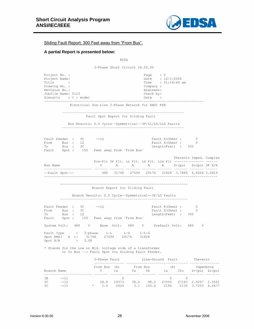
Sliding Fault Report: 300 Feet away from “From Bus”.
A partial Report is presented below: EDSA 3-Phase Short Circuit v6.00.00 Project No. : Page : 2 Project Name: Date : 12/1/2006 Title : Time : 01:14:44 am Drawing No. : Company : Revision No.: Engineer: Jobfile Name: T123 Check by: Scenario : 1 : mode1 Date : -------------------------------------------------------------------------------- Electrical One-Line 3-Phase Network for ANSI PDE ------------------------------------------------------------- Fault Spot Report for Sliding Fault Bus Results: 0.5 Cycle--Symmetrical--3P/LL/LG/LLG Faults ------------------------------------------------------------- Fault Feeder : 3C ->12 Fault R(Ohms) : 0 From Bus : 12 Fault X(Ohms) : 0 To Bus : 3C Length(Feet) : 300 Fault Spot : 150 Feet away from 'From Bus' Thevenin Imped. Complex Pre-Flt 3P Flt. LL Flt. LG Flt. LLG Flt --------------- ------ Bus Name V A A A A Z+(pu) Zo(pu) 3P X/R ------------------------ ------- ------- ------- ------- ------- ------- ------- ------ --Fault Spot--- 480 31748 27494 29176 31828 3.7886 4.8206 3.0819 --------------------------------------------------------------------------------------- ---------------------------------------------------------------- Branch Report for Sliding Fault Branch Results: 0.5 Cycle--Symmetrical--3P/LG Faults ---------------------------------------------------------------- Fault Feeder : 3C ->12 Fault R(Ohms) : 0 From Bus : 3C Fault X(Ohms) : 0 To Bus : 12 Length(Feet) : 300 Fault Spot : 150 Feet away from 'From Bus' System Volt: 480 V Base Volt: 480 V Prefault Volt: 480 V Fault Type : 3-phase L-L L-G L-L-G Spot RMS( A ): 31748 27494 29176 31828 Spot X/R : 3.08 * Stands for the Low or Mid. voltage side of a transformer or To Bus --> Fault Spot for Sliding Fault Feeder. 3-Phase Fault Line-Ground Fault Thevenin --------------- ------------------------------- --------------- From Bus (A) From Bus (A) Impedance Branch Name V Ia Va Vb Ia 3Io Z+(pu) Zo(pu) ------------------------ ------- ------- ------- ------- ------- ------- ------- ------- 3B ->11 0 0 0 3C ->12 28.8 29373 38.6 98.2 27050 27163 2.9297 2.5561 3C ->12 * 2.4 2426 3.1 100.4 2194 2135 3.7253 4.6677
Short Circuit Analysis Program ANSI/IEC/IEEE
Version 6.00.00 29 November 2006
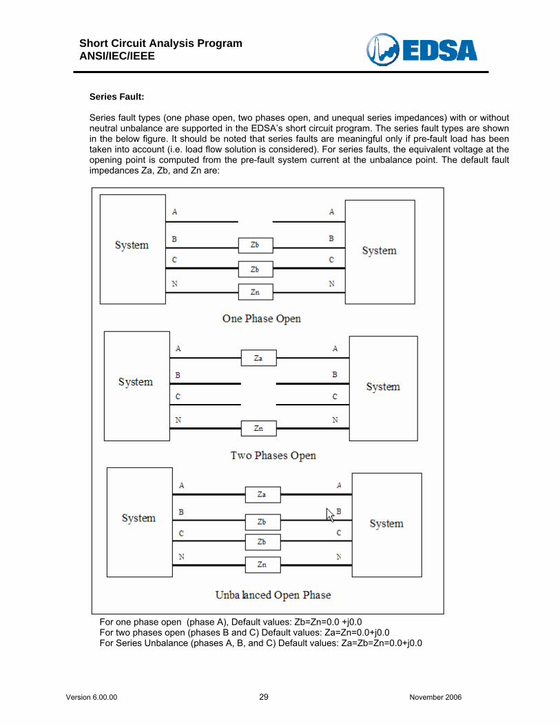
Series Fault: Series fault types (one phase open, two phases open, and unequal series impedances) with or without neutral unbalance are supported in the EDSA’s short circuit program. The series fault types are shown in the below figure. It should be noted that series faults are meaningful only if pre-fault load has been taken into account (i.e. load flow solution is considered). For series faults, the equivalent voltage at the opening point is computed from the pre-fault system current at the unbalance point. The default fault impedances Za, Zb, and Zn are:
For one phase open (phase A), Default values: Zb=Zn=0.0 +j0.0 For two phases open (phases B and C) Default values: Za=Zn=0.0+j0.0 For Series Unbalance (phases A, B, and C) Default values: Za=Zb=Zn=0.0+j0.0
Short Circuit Analysis Program ANSI/IEC/IEEE
Version 6.00.00 30 November 2006
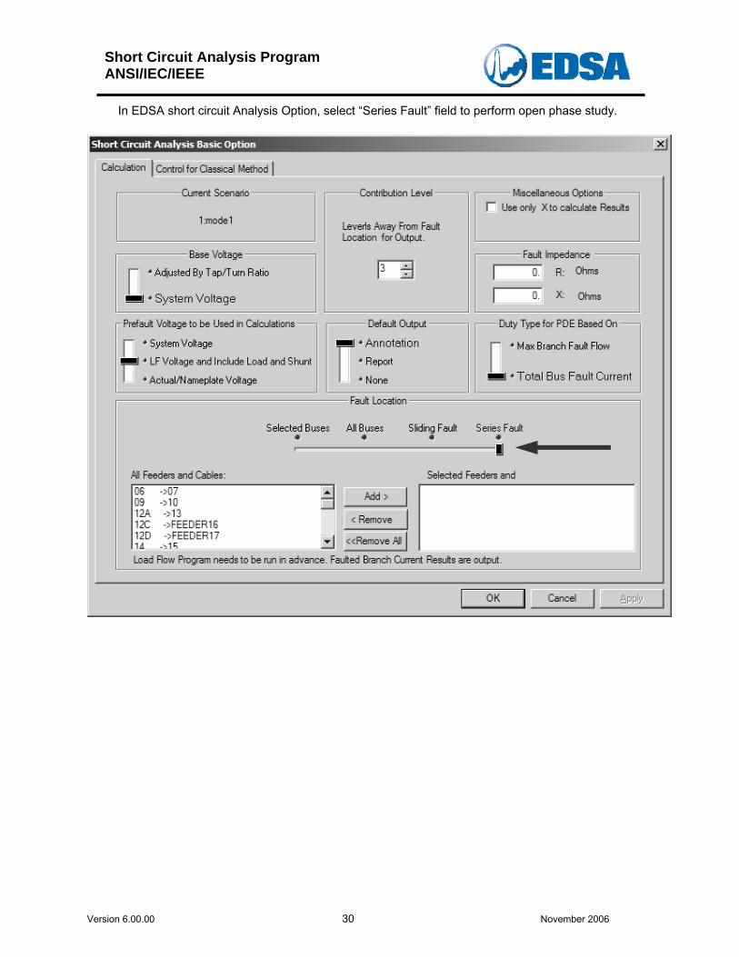
In EDSA short circuit Analysis Option, select “Series Fault” field to perform open phase study.
Short Circuit Analysis Program ANSI/IEC/IEEE
Version 6.00.00 31 November 2006
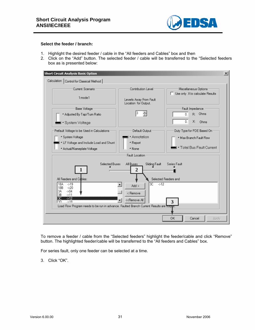
Select the feeder / branch: 1. Highlight the desired feeder / cable in the “All feeders and Cables” box and then 2. Click on the “Add” button. The selected feeder / cable will be transferred to the “Selected feeders
box as is presented below:
1 2
3
To remove a feeder / cable from the “Selected feeders” highlight the feeder/cable and click “Remove” button. The highlighted feeder/cable will be transferred to the “All feeders and Cables” box. For series fault, only one feeder can be selected at a time. 3. Click “OK”.
Short Circuit Analysis Program ANSI/IEC/IEEE
Version 6.00.00 32 November 2006
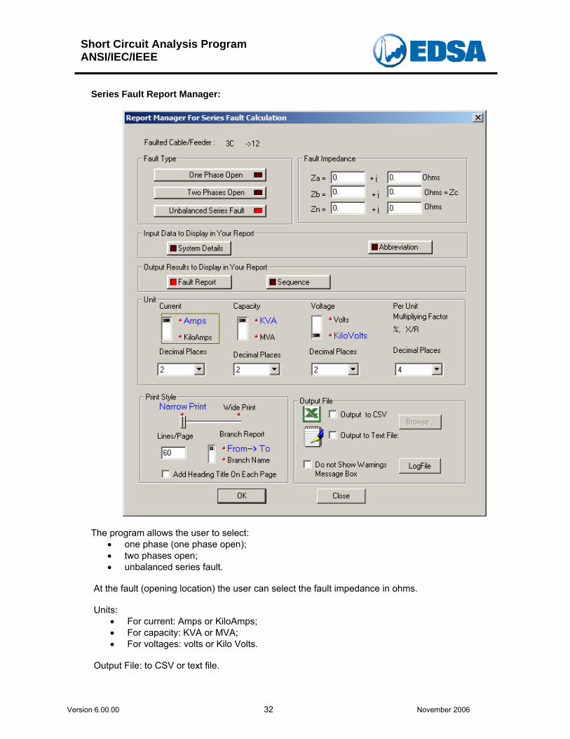
Series Fault Report Manager:
The program allows the user to select: • one phase (one phase open); • two phases open; • unbalanced series fault.
At the fault (opening location) the user can select the fault impedance in ohms. Units:
• For current: Amps or KiloAmps; • For capacity: KVA or MVA; • For voltages: volts or Kilo Volts.
Output File: to CSV or text file.

Short Circuit Analysis Program ANSI/IEC/IEEE
Version 6.00.00 33 November 2006
Report is listed below: EDSA 3-Phase Short Circuit v6.00.00 Project No. : Page : 1 Project Name: Date : 12/1/2006 Title : Time : 02:05:15 am Drawing No. : Company : Revision No.: Engineer: Jobfile Name: T123 Check by: Scenario : 1 : mode1 Date : -------------------------------------------------------------------------------- Electrical One-Line 3-Phase Network for ANSI PDE Base MVA : 100.000 System Frequence(Hz) : 60 # of Total Buses : 48 # of Active Buses : 48 # of Total Branches : 47 # of Active Sources : 3 # of Active Motors : 4 # of Active Shunts : 0 # of Transformers : 5 Reference Temperature(°C) : 20.0 Impedance Displaying Temperature(°C) : 20.0 Calculating Series Fault Classical Calculation Complex Z for X/R and Fault Current Transformer Phase Shift is not considered. Base Voltages : Use System Voltages Prefault Voltages : Use Load Flow Results ------------------------------------ Feeder/Cable Series Fault Report ------------------------------------ Fault Feeder : 3C ->12 Prefault Voltage System Base -------------------------- Bus Bus Name kV kV kV % Degree ----- ------------------------ -------- -------- -------- -------- -------- From 04 0.48 0.48 0.48 100.03 0.00 To 12 0.48 0.48 0.48 99.94 -0.0 Fault Impedance(Ohms) : Za = 0 +j 0 Zb = Zc = 0 +j 0 Zn = 0 +j 0 Fault Current Direction : From Bus --> To Bus Phase Sym Fault Current at 1/2 Cycle (Magnitude in A , Angle in Degree) ---- One Phase Open ------ Item Phase A Phase B Phase C ----- -------- -------- -------- Magn. 0 95 94 Angle 0 -122 109.4 ---------------------------------------------------------------------------------------
Short Circuit Analysis Program ANSI/IEC/IEEE
Version 6.00.00 34 November 2006
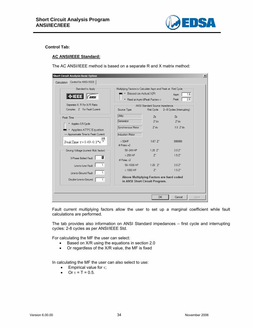
Control Tab:
AC ANSI/IEEE Standard: The AC ANSI/IEEE method is based on a separate R and X matrix method:
Fault current multiplying factors allow the user to set up a marginal coefficient while fault calculations are performed. The tab provides also information on ANSI Standard impedances – first cycle and interrupting cycles: 2-8 cycles as per ANSI/IEEE Std. For calculating the MF the user can select:
• Based on X/R using the equations in section 2.0 • Or regardless of the X/R value, the MF is fixed
In calculating the MF the user can also select to use: • Empirical value for τ; • Or τ = T = 0.5.
Short Circuit Analysis Program ANSI/IEC/IEEE
Version 6.00.00 35 November 2006
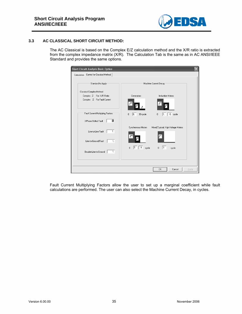
3.3 AC CLASSICAL SHORT CIRCUIT METHOD:
The AC Classical is based on the Complex E/Z calculation method and the X/R ratio is extracted from the complex impedance matrix (X/R). The Calculation Tab is the same as in AC ANSI/IEEE Standard and provides the same options.
Fault Current Multiplying Factors allow the user to set up a marginal coefficient while fault calculations are performed. The user can also select the Machine Current Decay, in cycles.
Short Circuit Analysis Program ANSI/IEC/IEEE
Version 6.00.00 36 November 2006
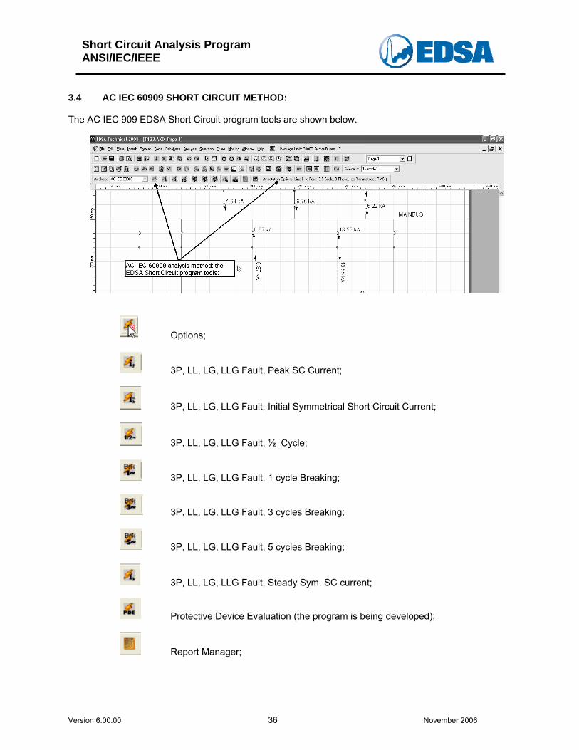
3.4 AC IEC 60909 SHORT CIRCUIT METHOD:
The AC IEC 909 EDSA Short Circuit program tools are shown below.
Options;
3P, LL, LG, LLG Fault, Peak SC Current;
3P, LL, LG, LLG Fault, Initial Symmetrical Short Circuit Current;
3P, LL, LG, LLG Fault, ½ Cycle;
3P, LL, LG, LLG Fault, 1 cycle Breaking;
3P, LL, LG, LLG Fault, 3 cycles Breaking;
3P, LL, LG, LLG Fault, 5 cycles Breaking;
3P, LL, LG, LLG Fault, Steady Sym. SC current;
Protective Device Evaluation (the program is being developed);
Report Manager;
Short Circuit Analysis Program ANSI/IEC/IEEE
Version 6.00.00 37 November 2006
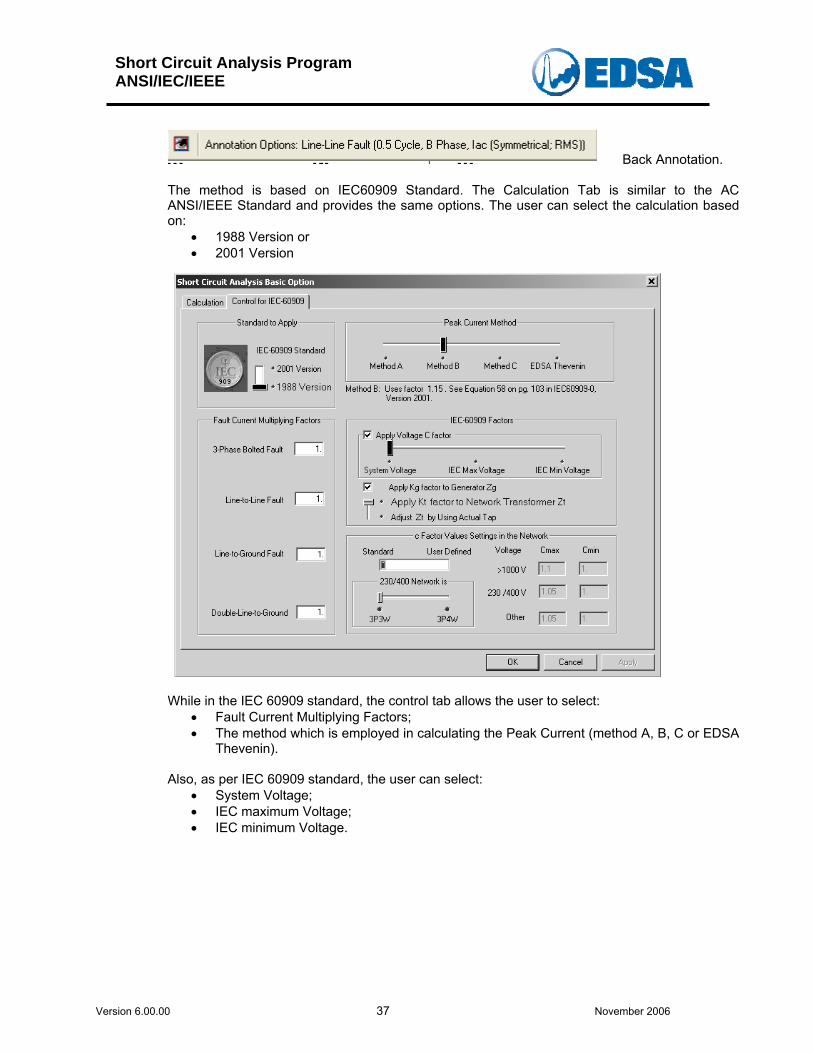
Back Annotation. The method is based on IEC60909 Standard. The Calculation Tab is similar to the AC ANSI/IEEE Standard and provides the same options. The user can select the calculation based on:
• 1988 Version or • 2001 Version
While in the IEC 60909 standard, the control tab allows the user to select:
• Fault Current Multiplying Factors; • The method which is employed in calculating the Peak Current (method A, B, C or EDSA
Thevenin). Also, as per IEC 60909 standard, the user can select:
• System Voltage; • IEC maximum Voltage; • IEC minimum Voltage.
Short Circuit Analysis Program ANSI/IEC/IEEE
Version 6.00.00 38 November 2006
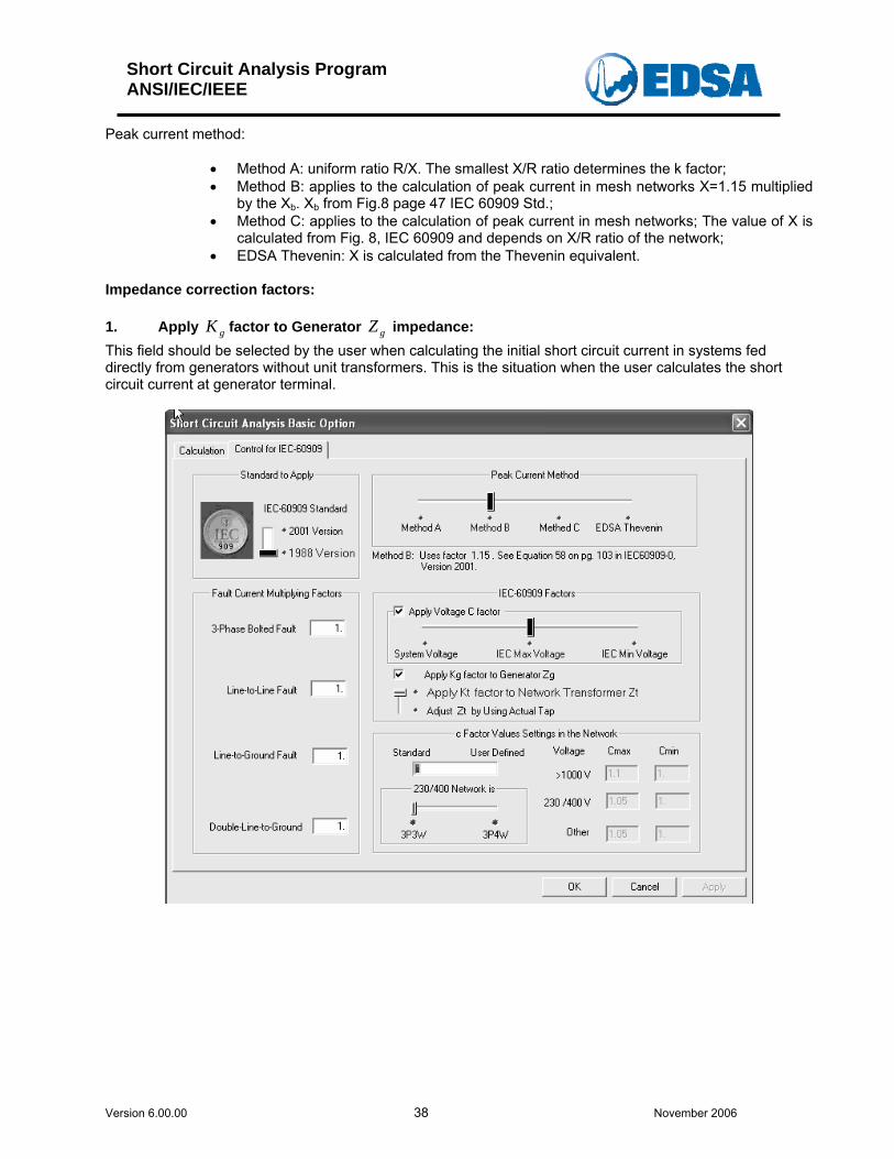
Peak current method:
• Method A: uniform ratio R/X. The smallest X/R ratio determines the k factor; • Method B: applies to the calculation of peak current in mesh networks X=1.15 multiplied
by the Xb. Xb from Fig.8 page 47 IEC 60909 Std.; • Method C: applies to the calculation of peak current in mesh networks; The value of X is
calculated from Fig. 8, IEC 60909 and depends on X/R ratio of the network; • EDSA Thevenin: X is calculated from the Thevenin equivalent.
Impedance correction factors: 1. Apply gK factor to Generator impedance: gZThis field should be selected by the user when calculating the initial short circuit current in systems fed directly from generators without unit transformers. This is the situation when the user calculates the short circuit current at generator terminal.
Short Circuit Analysis Program ANSI/IEC/IEEE
Version 6.00.00 39 November 2006
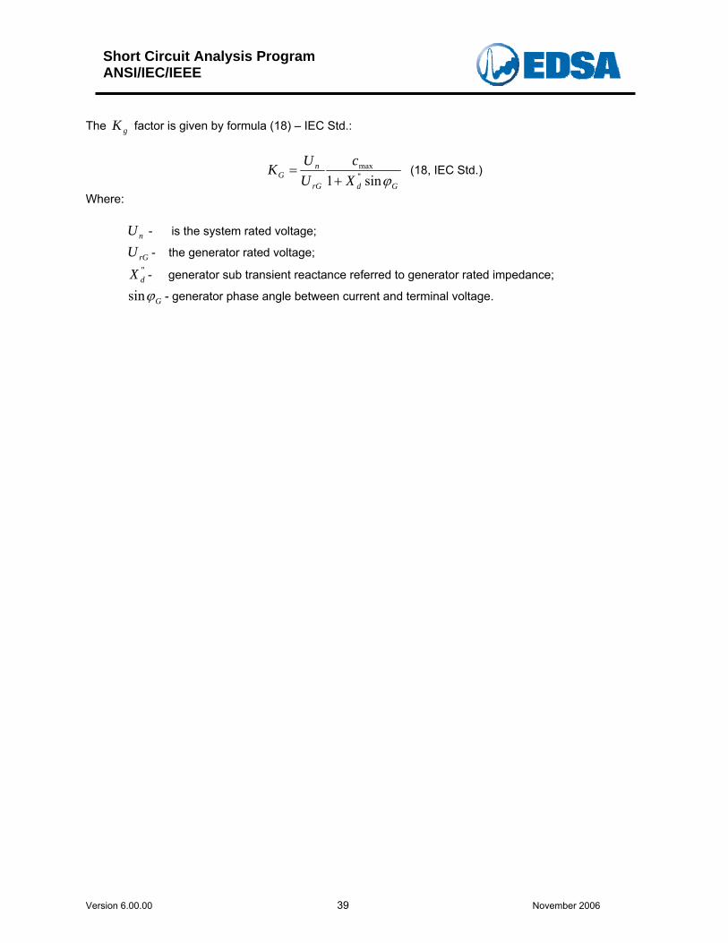
The factor is given by formula (18) – IEC Std.: gK
GdrG
nG X
cUUK
ϕsin1 "max
+= (18, IEC Std.)
Where:
nU - is the system rated voltage;
rGU - the generator rated voltage; "dX - generator sub transient reactance referred to generator rated impedance;
Gϕsin - generator phase angle between current and terminal voltage.
Short Circuit Analysis Program ANSI/IEC/IEEE
Version 6.00.00 40 November 2006
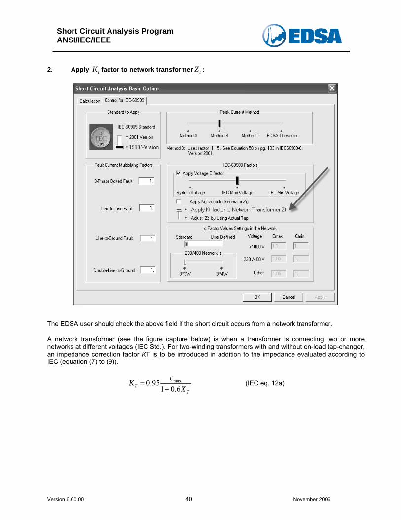
2. Apply factor to network transformer : tK tZ
The EDSA user should check the above field if the short circuit occurs from a network transformer. A network transformer (see the figure capture below) is when a transformer is connecting two or more networks at different voltages (IEC Std.). For two-winding transformers with and without on-load tap-changer, an impedance correction factor KT is to be introduced in addition to the impedance evaluated according to IEC (equation (7) to (9)).
TT X
cK6.01
95.0 max
+= (IEC eq. 12a)
Short Circuit Analysis Program ANSI/IEC/IEEE
Version 6.00.00 41 November 2006
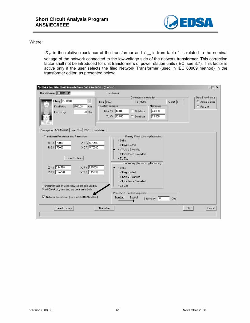
Where:
TX is the relative reactance of the transformer and c is from table 1 is related to the nominal voltage of the network connected to the low-voltage side of the network transformer. This correction factor shall not be introduced for unit transformers of power station units (IEC, see 3.7). This factor is active only if the user selects the filed Network Transformer (used in IEC 60909 method) in the transformer editor, as presented below:
max
Short Circuit Analysis Program ANSI/IEC/IEEE
Version 6.00.00 42 November 2006
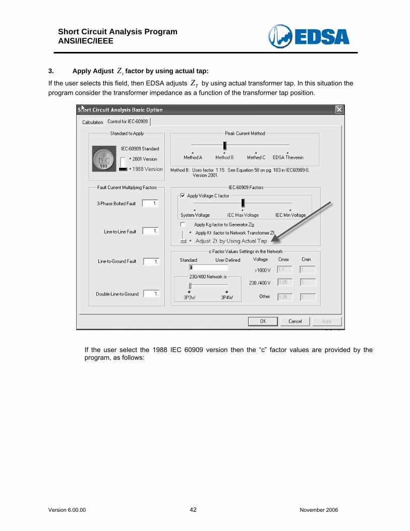
3. Apply Adjust factor by using actual tap: tZIf the user selects this field, then EDSA adjusts by using actual transformer tap. In this situation the program consider the transformer impedance as a function of the transformer tap position.
TZ
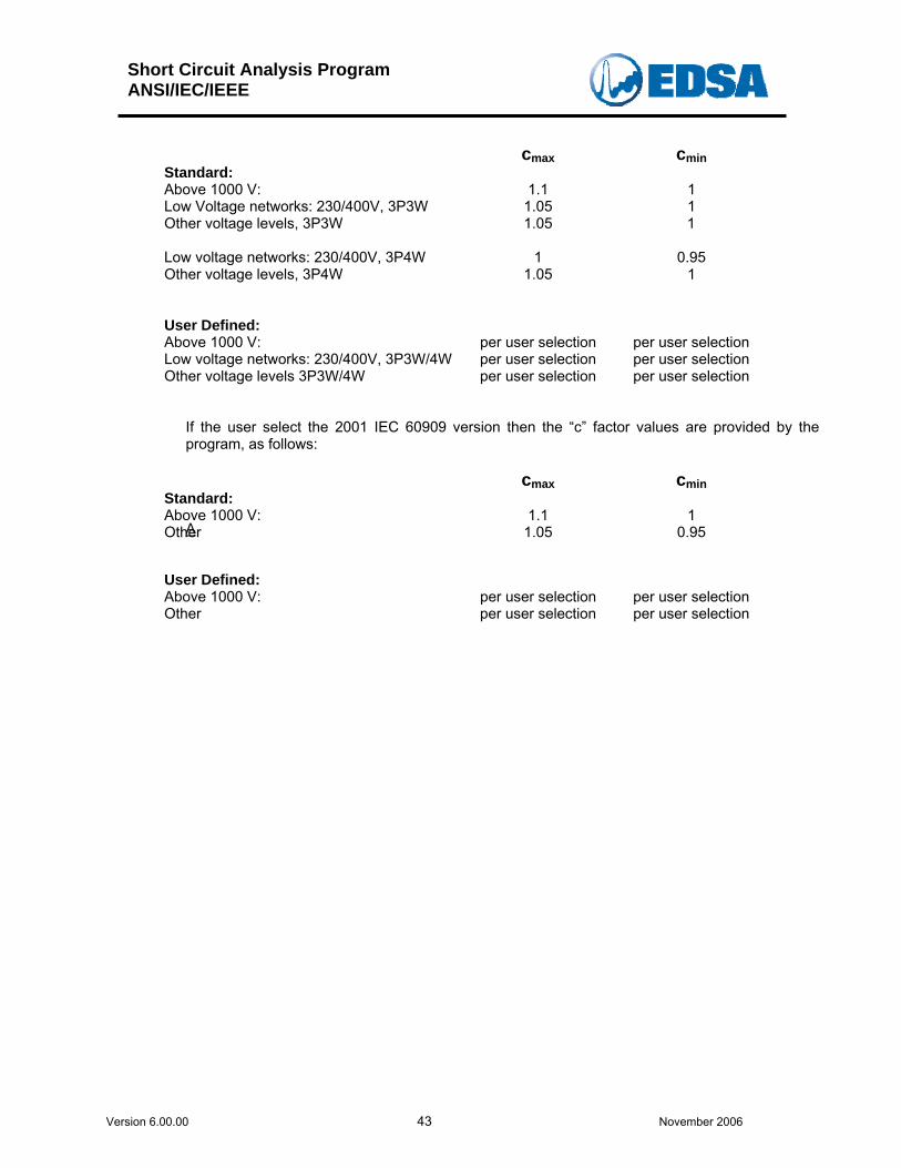
If the user select the 1988 IEC 60909 version then the “c” factor values are provided by the program, as follows:
Short Circuit Analysis Program ANSI/IEC/IEEE
Version 6.00.00 43 November 2006
cmax cmin Standard: Above 1000 V: 1.1 1 Low Voltage networks: 230/400V, 3P3W Other voltage levels, 3P3W
1.05 1.05
1 1
Low voltage networks: 230/400V, 3P4W Other voltage levels, 3P4W
1
1.05
0.95
1
User Defined: Above 1000 V: per user selection per user selection Low voltage networks: 230/400V, 3P3W/4W Other voltage levels 3P3W/4W
per user selection per user selection
per user selection per user selection
If the user select the 2001 IEC 60909 version then the “c” factor values are provided by the program, as follows:
A Other
cmax cmin Standard: Above 1000 V: 1.1 1
1.05
0.95
User Defined: Above 1000 V: Other
per user selection per user selection
per user selection
per user selection
Short Circuit Analysis Program ANSI/IEC/IEEE
Version 6.00.00 44 November 2006
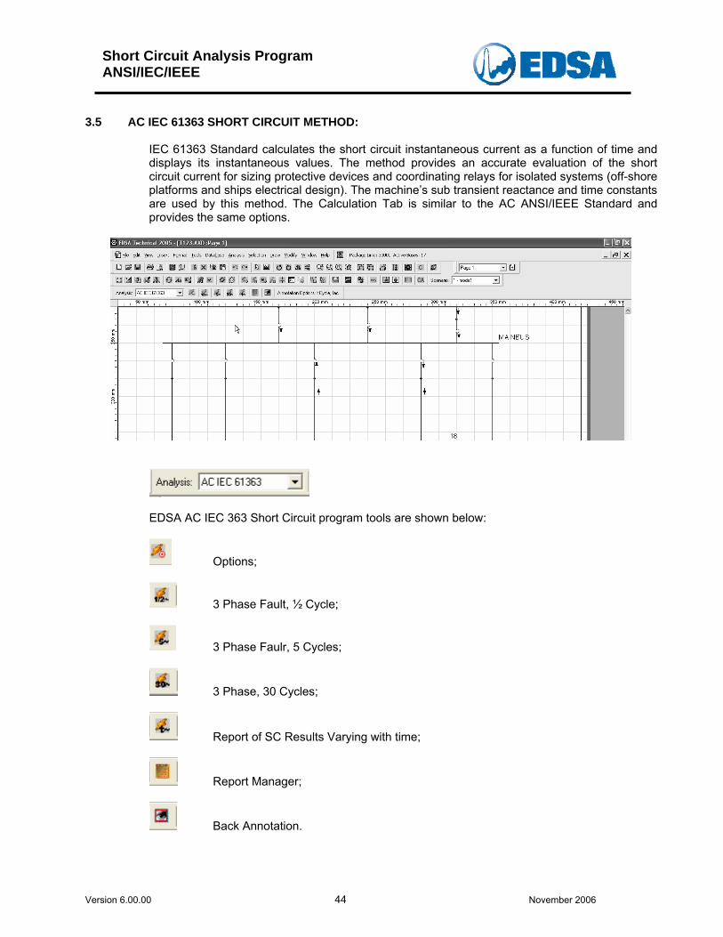
3.5 AC IEC 61363 SHORT CIRCUIT METHOD:
IEC 61363 Standard calculates the short circuit instantaneous current as a function of time and displays its instantaneous values. The method provides an accurate evaluation of the short circuit current for sizing protective devices and coordinating relays for isolated systems (off-shore platforms and ships electrical design). The machine’s sub transient reactance and time constants are used by this method. The Calculation Tab is similar to the AC ANSI/IEEE Standard and provides the same options.
EDSA AC IEC 363 Short Circuit program tools are shown below:
Options;
3 Phase Fault, ½ Cycle;
3 Phase Faulr, 5 Cycles;
3 Phase, 30 Cycles;
Report of SC Results Varying with time;
Report Manager;
Back Annotation.
Short Circuit Analysis Program ANSI/IEC/IEEE
Version 6.00.00 45 November 2006
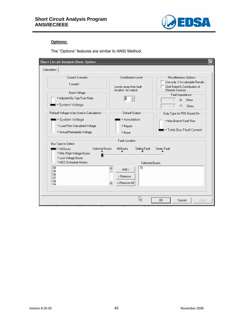
Options: The “Options” features are similar to ANSI Method.
Short Circuit Analysis Program ANSI/IEC/IEEE
Version 6.00.00 46 November 2006
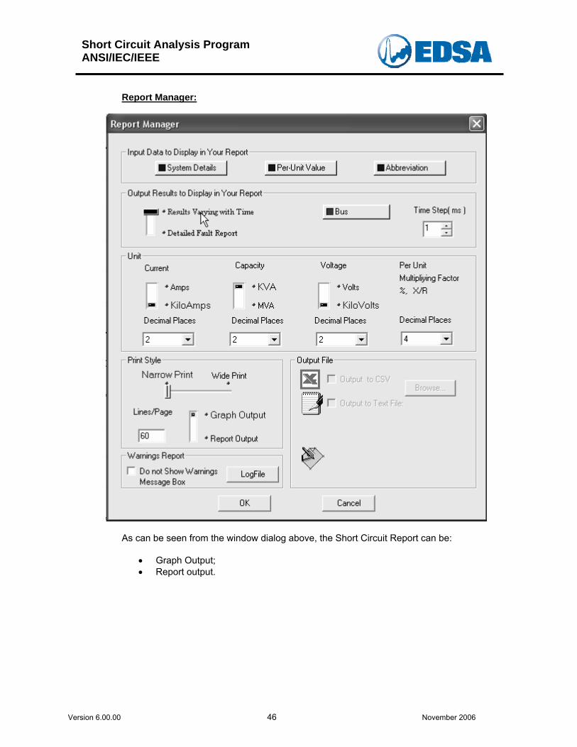
Report Manager:
As can be seen from the window dialog above, the Short Circuit Report can be:
• Graph Output; • Report output.
Short Circuit Analysis Program ANSI/IEC/IEEE
Version 6.00.00 47 November 2006
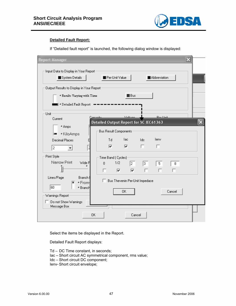
Detailed Fault Report: If “Detailed fault report” is launched, the following dialog window is displayed:
Select the items be displayed in the Report. Detailed Fault Report displays: Td – DC Time constant, in seconds; Iac – Short circuit AC symmetrical component, rms value; Idc – Short circuit DC component; Ienv- Short circuit envelope;
Short Circuit Analysis Program ANSI/IEC/IEEE
Version 6.00.00 48 November 2006
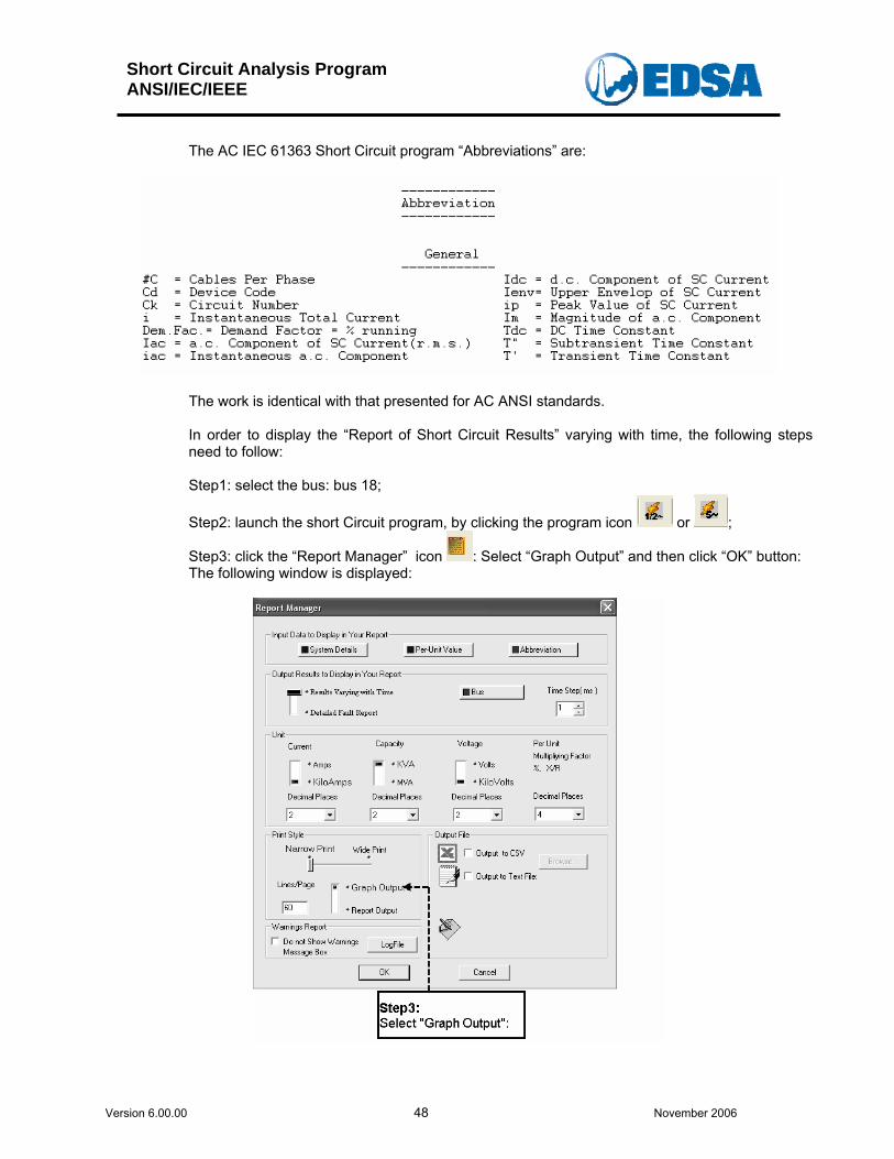
The AC IEC 61363 Short Circuit program “Abbreviations” are:
The work is identical with that presented for AC ANSI standards. In order to display the “Report of Short Circuit Results” varying with time, the following steps need to follow: Step1: select the bus: bus 18;
Step2: launch the short Circuit program, by clicking the program icon or ;
Step3: click the “Report Manager” icon : Select “Graph Output” and then click “OK” button: The following window is displayed:
Short Circuit Analysis Program ANSI/IEC/IEEE
Version 6.00.00 49 November 2006
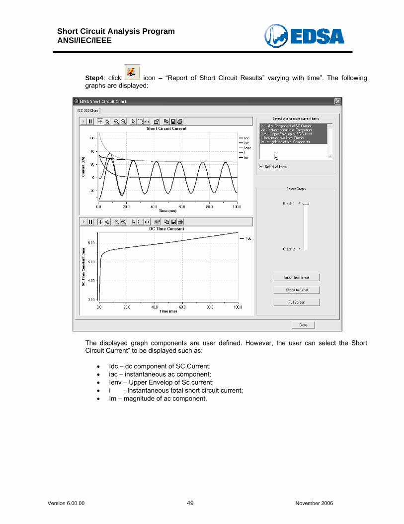
Step4: click icon – “Report of Short Circuit Results” varying with time”. The following graphs are displayed:
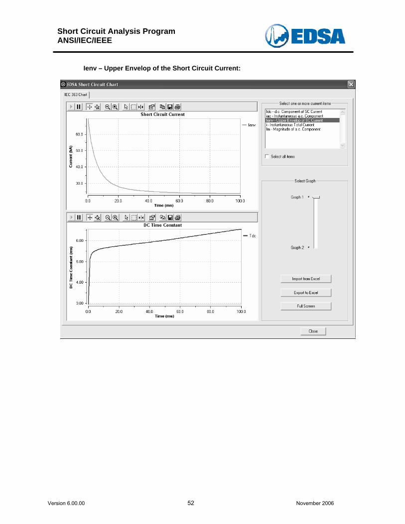
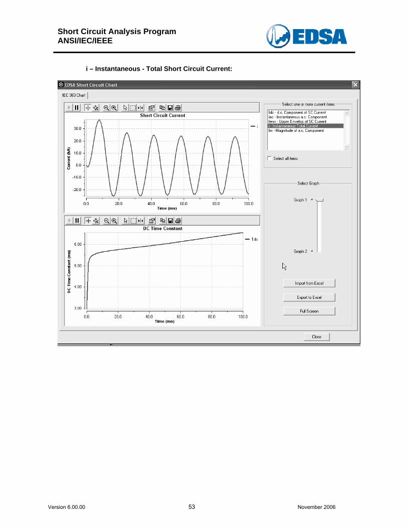
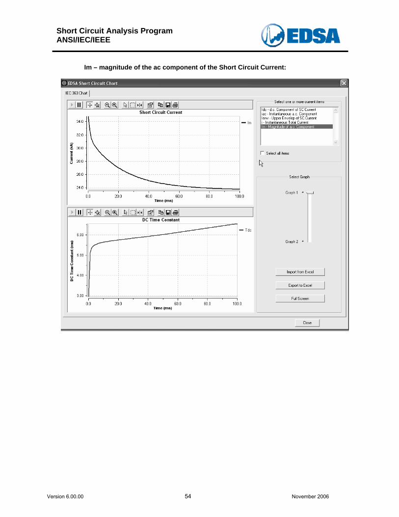
The displayed graph components are user defined. However, the user can select the Short Circuit Current” to be displayed such as:
• Idc – dc component of SC Current; • iac – instantaneous ac component; • Ienv – Upper Envelop of Sc current; • i - Instantaneous total short circuit current; • Im – magnitude of ac component.
Short Circuit Analysis Program ANSI/IEC/IEEE
Version 6.00.00 50 November 2006
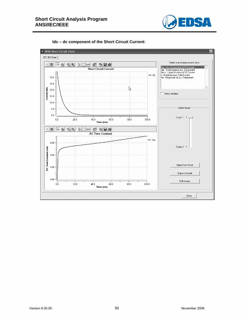
Idc – dc component of the Short Circuit Current:
Short Circuit Analysis Program ANSI/IEC/IEEE
Version 6.00.00 51 November 2006
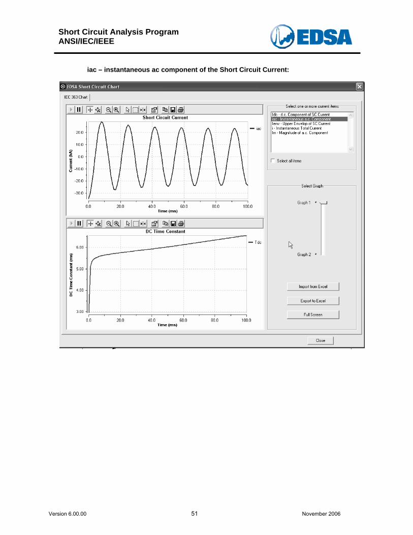
iac – instantaneous ac component of the Short Circuit Current:
Short Circuit Analysis Program ANSI/IEC/IEEE
Version 6.00.00 52 November 2006
Ienv – Upper Envelop of the Short Circuit Current:
Short Circuit Analysis Program ANSI/IEC/IEEE
Version 6.00.00 53 November 2006
i – Instantaneous - Total Short Circuit Current:
Short Circuit Analysis Program ANSI/IEC/IEEE
Version 6.00.00 54 November 2006
Im – magnitude of the ac component of the Short Circuit Current:
Short Circuit Analysis Program ANSI/IEC/IEEE
Version 6.00.00 55 November 2006
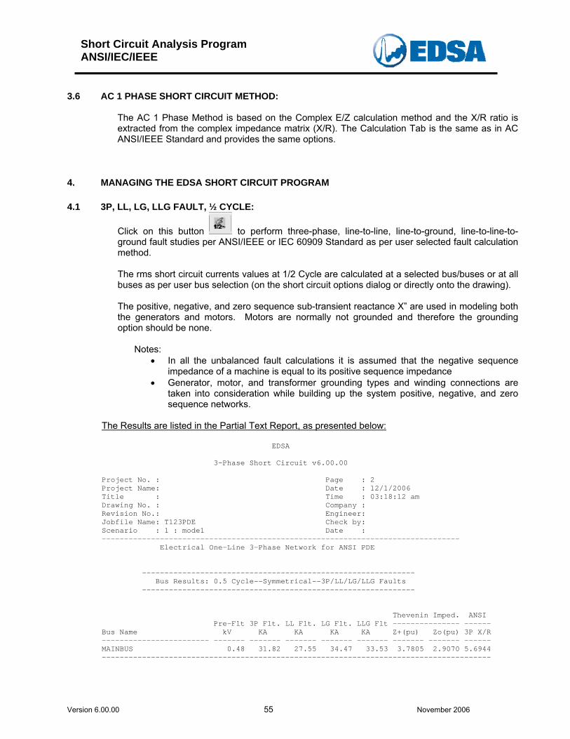
3.6 AC 1 PHASE SHORT CIRCUIT METHOD:
The AC 1 Phase Method is based on the Complex E/Z calculation method and the X/R ratio is extracted from the complex impedance matrix (X/R). The Calculation Tab is the same as in AC ANSI/IEEE Standard and provides the same options.
4. MANAGING THE EDSA SHORT CIRCUIT PROGRAM 4.1 3P, LL, LG, LLG FAULT, ½ CYCLE:
Click on this button to perform three-phase, line-to-line, line-to-ground, line-to-line-to-ground fault studies per ANSI/IEEE or IEC 60909 Standard as per user selected fault calculation method.
The rms short circuit currents values at 1/2 Cycle are calculated at a selected bus/buses or at all buses as per user bus selection (on the short circuit options dialog or directly onto the drawing).
The positive, negative, and zero sequence sub-transient reactance X” are used in modeling both the generators and motors. Motors are normally not grounded and therefore the grounding option should be none.
Notes:
• In all the unbalanced fault calculations it is assumed that the negative sequence impedance of a machine is equal to its positive sequence impedance
• Generator, motor, and transformer grounding types and winding connections are taken into consideration while building up the system positive, negative, and zero sequence networks.
The Results are listed in the Partial Text Report, as presented below:
EDSA 3-Phase Short Circuit v6.00.00 Project No. : Page : 2 Project Name: Date : 12/1/2006 Title : Time : 03:18:12 am Drawing No. : Company : Revision No.: Engineer: Jobfile Name: T123PDE Check by: Scenario : 1 : mode1 Date : -------------------------------------------------------------------------------- Electrical One-Line 3-Phase Network for ANSI PDE ------------------------------------------------------------- Bus Results: 0.5 Cycle--Symmetrical--3P/LL/LG/LLG Faults ------------------------------------------------------------- Thevenin Imped. ANSI Pre-Flt 3P Flt. LL Flt. LG Flt. LLG Flt --------------- ------ Bus Name kV KA KA KA KA Z+(pu) Zo(pu) 3P X/R ------------------------ ------- ------- ------- ------- ------- ------- ------- ------ MAINBUS 0.48 31.82 27.55 34.47 33.53 3.7805 2.9070 5.6944 ---------------------------------------------------------------------------------------
Short Circuit Analysis Program ANSI/IEC/IEEE
Version 6.00.00 56 November 2006
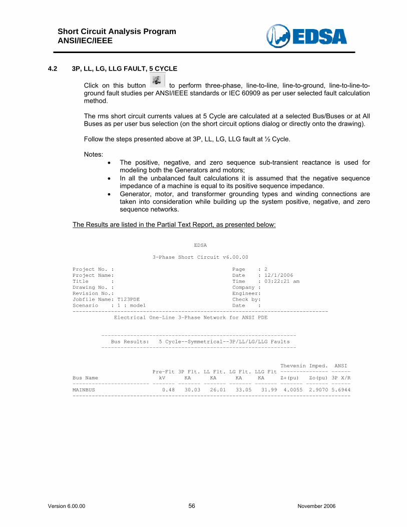
4.2 3P, LL, LG, LLG FAULT, 5 CYCLE
Click on this button to perform three-phase, line-to-line, line-to-ground, line-to-line-to-ground fault studies per ANSI/IEEE standards or IEC 60909 as per user selected fault calculation method.
The rms short circuit currents values at 5 Cycle are calculated at a selected Bus/Buses or at All Buses as per user bus selection (on the short circuit options dialog or directly onto the drawing).
Follow the steps presented above at 3P, LL, LG, LLG fault at ½ Cycle.
Notes:
• The positive, negative, and zero sequence sub-transient reactance is used for modeling both the Generators and motors;
• In all the unbalanced fault calculations it is assumed that the negative sequence impedance of a machine is equal to its positive sequence impedance.
• Generator, motor, and transformer grounding types and winding connections are taken into consideration while building up the system positive, negative, and zero sequence networks.
The Results are listed in the Partial Text Report, as presented below:
EDSA 3-Phase Short Circuit v6.00.00 Project No. : Page : 2 Project Name: Date : 12/1/2006 Title : Time : 03:22:21 am Drawing No. : Company : Revision No.: Engineer: Jobfile Name: T123PDE Check by: Scenario : 1 : mode1 Date : -------------------------------------------------------------------------------- Electrical One-Line 3-Phase Network for ANSI PDE ------------------------------------------------------------- Bus Results: 5 Cycle--Symmetrical--3P/LL/LG/LLG Faults ------------------------------------------------------------- Thevenin Imped. ANSI Pre-Flt 3P Flt. LL Flt. LG Flt. LLG Flt --------------- ------ Bus Name kV KA KA KA KA Z+(pu) Zo(pu) 3P X/R ------------------------ ------- ------- ------- ------- ------- ------- ------- ------ MAINBUS 0.48 30.03 26.01 33.05 31.99 4.0055 2.9070 5.6944 ---------------------------------------------------------------------------------------
Short Circuit Analysis Program ANSI/IEC/IEEE
Version 6.00.00 57 November 2006
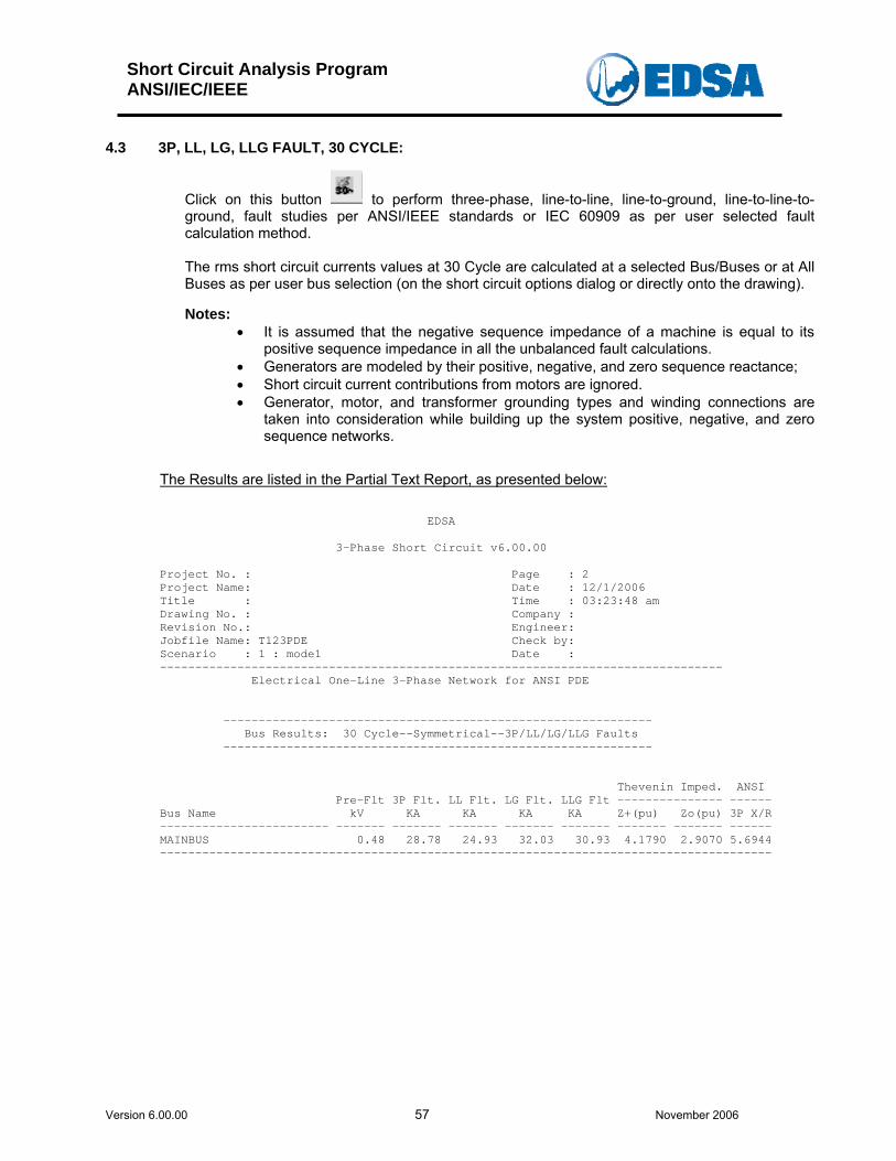
4.3 3P, LL, LG, LLG FAULT, 30 CYCLE:
Click on this button to perform three-phase, line-to-line, line-to-ground, line-to-line-to-ground, fault studies per ANSI/IEEE standards or IEC 60909 as per user selected fault calculation method.
The rms short circuit currents values at 30 Cycle are calculated at a selected Bus/Buses or at All Buses as per user bus selection (on the short circuit options dialog or directly onto the drawing).
Notes:
• It is assumed that the negative sequence impedance of a machine is equal to its positive sequence impedance in all the unbalanced fault calculations.
• Generators are modeled by their positive, negative, and zero sequence reactance; • Short circuit current contributions from motors are ignored. • Generator, motor, and transformer grounding types and winding connections are
taken into consideration while building up the system positive, negative, and zero sequence networks.
The Results are listed in the Partial Text Report, as presented below:
EDSA 3-Phase Short Circuit v6.00.00 Project No. : Page : 2 Project Name: Date : 12/1/2006 Title : Time : 03:23:48 am Drawing No. : Company : Revision No.: Engineer: Jobfile Name: T123PDE Check by: Scenario : 1 : mode1 Date : -------------------------------------------------------------------------------- Electrical One-Line 3-Phase Network for ANSI PDE ------------------------------------------------------------- Bus Results: 30 Cycle--Symmetrical--3P/LL/LG/LLG Faults ------------------------------------------------------------- Thevenin Imped. ANSI Pre-Flt 3P Flt. LL Flt. LG Flt. LLG Flt --------------- ------ Bus Name kV KA KA KA KA Z+(pu) Zo(pu) 3P X/R ------------------------ ------- ------- ------- ------- ------- ------- ------- ------ MAINBUS 0.48 28.78 24.93 32.03 30.93 4.1790 2.9070 5.6944 ---------------------------------------------------------------------------------------
Short Circuit Analysis Program ANSI/IEC/IEEE
Version 6.00.00 58 November 2006
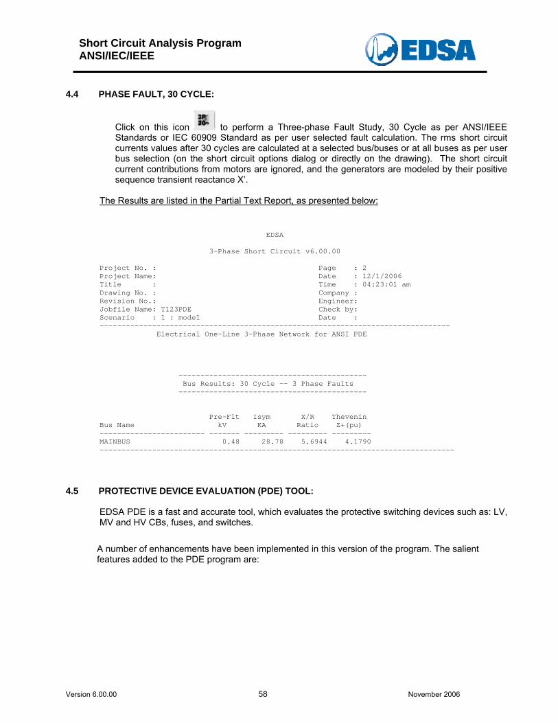
4.4 PHASE FAULT, 30 CYCLE:
Click on this icon to perform a Three-phase Fault Study, 30 Cycle as per ANSI/IEEE Standards or IEC 60909 Standard as per user selected fault calculation. The rms short circuit currents values after 30 cycles are calculated at a selected bus/buses or at all buses as per user bus selection (on the short circuit options dialog or directly on the drawing). The short circuit current contributions from motors are ignored, and the generators are modeled by their positive sequence transient reactance X’.
The Results are listed in the Partial Text Report, as presented below:
EDSA 3-Phase Short Circuit v6.00.00 Project No. : Page : 2 Project Name: Date : 12/1/2006 Title : Time : 04:23:01 am Drawing No. : Company : Revision No.: Engineer: Jobfile Name: T123PDE Check by: Scenario : 1 : mode1 Date : -------------------------------------------------------------------------------- Electrical One-Line 3-Phase Network for ANSI PDE ------------------------------------------- Bus Results: 30 Cycle -- 3 Phase Faults ------------------------------------------- Pre-Flt Isym X/R Thevenin Bus Name kV KA Ratio Z+(pu) ------------------------ ------- --------- --------- --------- MAINBUS 0.48 28.78 5.6944 4.1790 ---------------------------------------------------------------------------------
4.5 PROTECTIVE DEVICE EVALUATION (PDE) TOOL:
EDSA PDE is a fast and accurate tool, which evaluates the protective switching devices such as: LV, MV and HV CBs, fuses, and switches.
A number of enhancements have been implemented in this version of the program. The salient features added to the PDE program are:
Short Circuit Analysis Program ANSI/IEC/IEEE
Version 6.00.00 59 November 2006
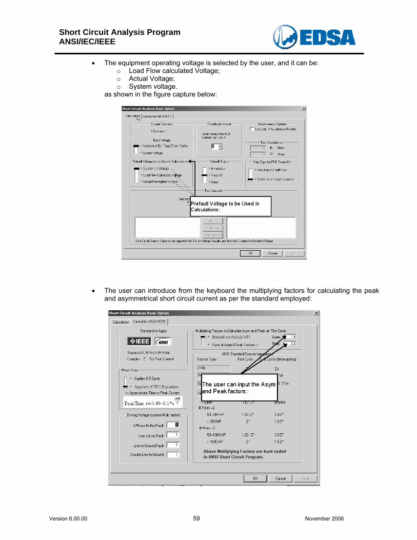
• The equipment operating voltage is selected by the user, and it can be: o Load Flow calculated Voltage; o Actual Voltage; o System voltage.
as shown in the figure capture below:
• The user can introduce from the keyboard the multiplying factors for calculating the peak
and asymmetrical short circuit current as per the standard employed:
Short Circuit Analysis Program ANSI/IEC/IEEE
Version 6.00.00 60 November 2006
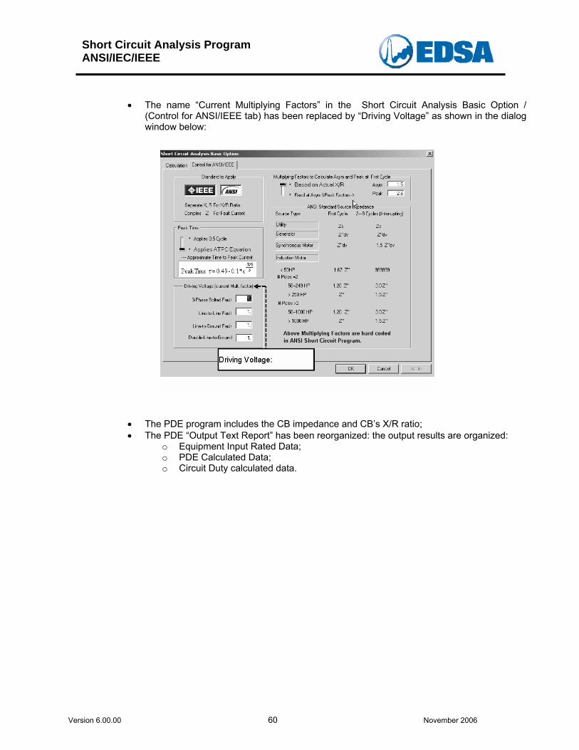
• The name “Current Multiplying Factors” in the Short Circuit Analysis Basic Option /
(Control for ANSI/IEEE tab) has been replaced by “Driving Voltage” as shown in the dialog window below:
• The PDE program includes the CB impedance and CB’s X/R ratio; • The PDE “Output Text Report” has been reorganized: the output results are organized:
o Equipment Input Rated Data; o PDE Calculated Data; o Circuit Duty calculated data.
Short Circuit Analysis Program ANSI/IEC/IEEE
Version 6.00.00 61 November 2006
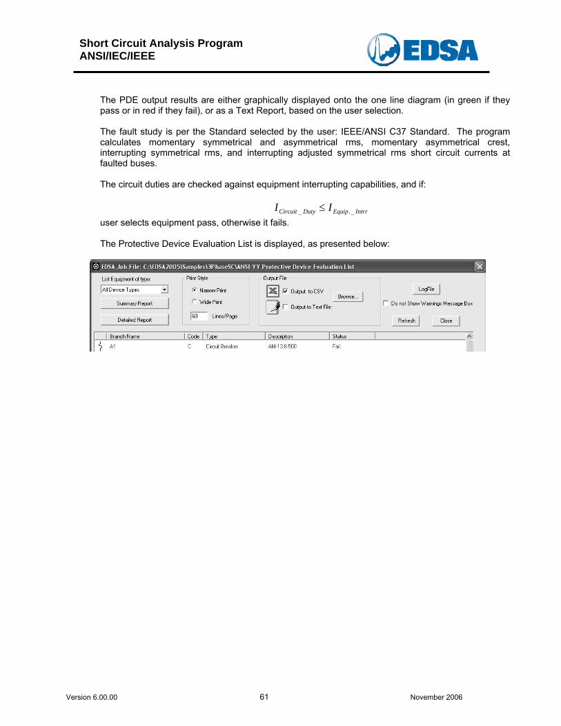
The PDE output results are either graphically displayed onto the one line diagram (in green if they pass or in red if they fail), or as a Text Report, based on the user selection.
The fault study is per the Standard selected by the user: IEEE/ANSI C37 Standard. The program calculates momentary symmetrical and asymmetrical rms, momentary asymmetrical crest, interrupting symmetrical rms, and interrupting adjusted symmetrical rms short circuit currents at faulted buses.
The circuit duties are checked against equipment interrupting capabilities, and if:
IntrrEquipDutyCircuit II _._ ≤ user selects equipment pass, otherwise it fails.
The Protective Device Evaluation List is displayed, as presented below:
Short Circuit Analysis Program ANSI/IEC/IEEE
Version 6.00.00 62 November 2006
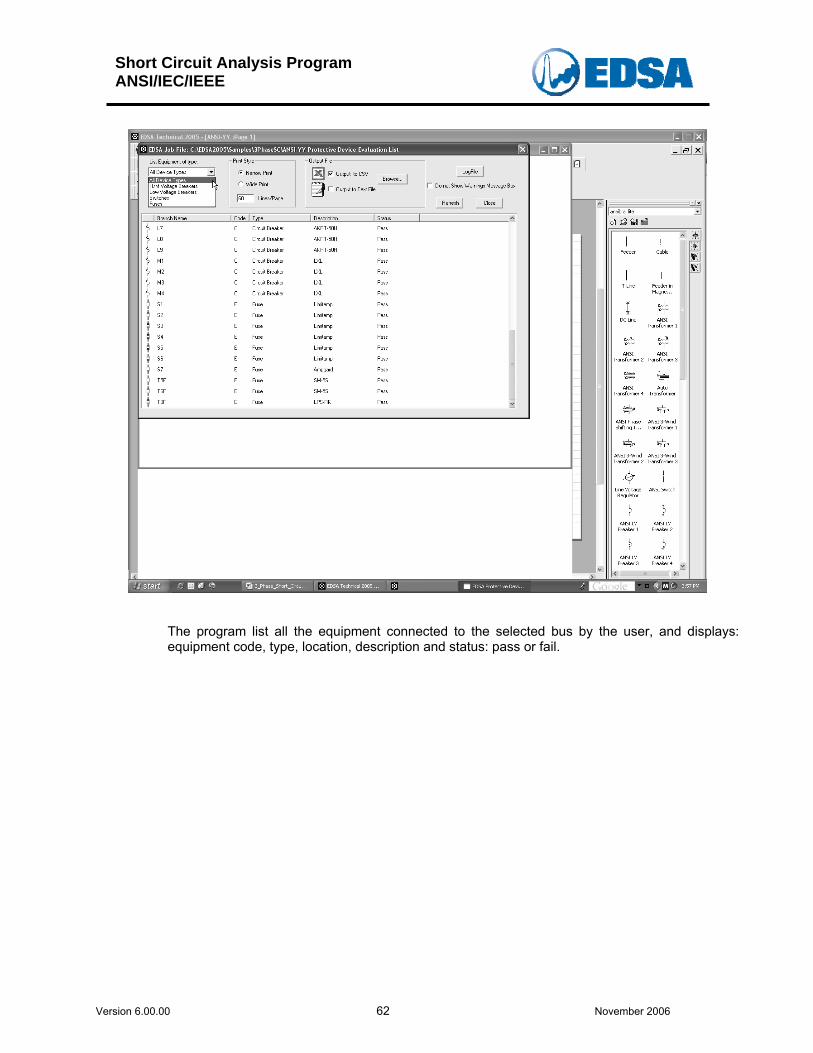
The program list all the equipment connected to the selected bus by the user, and displays: equipment code, type, location, description and status: pass or fail.
Short Circuit Analysis Program ANSI/IEC/IEEE
Version 6.00.00 63 November 2006
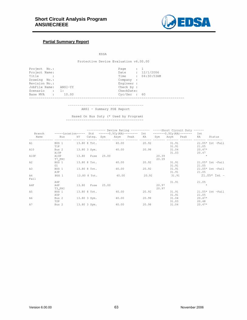
Partial Summary Report
EDSA Protective Device Evaluation v6.00.00 Project No.: Page : 1 Project Name: Date : 12/1/2006 Title : Time : 04:30:53AM Drawing No.: Company : Revision No.: Engineer : JobFile Name: ANSI-YY Check by : Scenario : 1: CheckDate: Base MVA : 10.00 Cyc/Sec : 60 -------------------------------------------------------------------------------- --------------------------------------- ANSI - Summary PDE Report Based On Bus Duty (* Used by Program) ---------------------------------------- ----------- Device Rating ----------- -----Short Circuit Duty ------ Branch -----Location----- Std ------0.5Cy(KA)-------- Int -------0.5Cy(KA)------- Int Name Bus kV Categ. Sym Asym Peak KA Sym Asym Peak KA Status -------------- ---------- ------- ------ ------- ------- ------- ------- ------- ------- ------- ------- --------- A1 BUS 1 13.80 8 Tot. 40.00 20.92 31.91 21.05* Int -Fail T1P 31.91 21.05 A10 Bus 2 13.80 3 Sym. 40.00 20.98 31.04 20.47* A10P 31.03 20.47 A10F A10P 13.80 Fuse 25.00 20.39 * T7_PRI 20.39 A2 BUS 1 13.80 8 Tot. 40.00 20.92 31.91 21.05* Int -Fail G1 31.91 21.05 A3 BUS 1 13.80 8 Tot. 40.00 20.92 31.91 21.05* Int -Fail A3P 31.91 21.05 A4 BUS 1 13.80 8 Tot. 40.00 20.92 31.91 21.05* Int -Fail A4P 31.91 21.05 A4F A4P 13.80 Fuse 25.00 20.97 * T3_PRI 20.97 A5 BUS 1 13.80 8 Tot. 40.00 20.92 31.91 21.05* Int -Fail A5P 31.91 21.05 A6 Bus 2 13.80 3 Sym. 40.00 20.98 31.04 20.47* T2P 31.03 20.48 A7 Bus 2 13.80 3 Sym. 40.00 20.98 31.04 20.47*
Short Circuit Analysis Program ANSI/IEC/IEEE
Version 6.00.00 64 November 2006
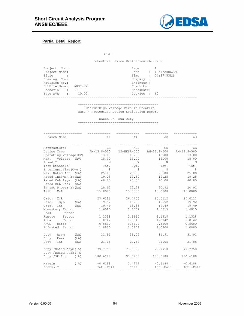
Partial Detail Report
EDSA Protective Device Evaluation v6.00.00 Project No.: Page : 1 Project Name: Date : 12/1/2006/06 Title : Time : 04:37:53AM Drawing No.: Company : Revision No.: Engineer : JobFile Name: ANSI-YY Check by : Scenario : 1: CheckDate: Base MVA : 10.00 Cyc/Sec : 60 -------------------------------------------------------------------------------- ------------------------------------------ Medium/High Voltage Circuit Breakers ANSI - Protective Device Evaluation Report Based On Bus Duty ------------------------------------------ -------------------- ------------ ------------ ------------ ------------ Branch Name A1 A10 A2 A3 -------------------- ------------ ------------ ------------ ------------ Manufacturer GE ABB GE GE Device Type AM-13.8-500 15-HKSA-500 AM-13.8-500 AM-13.8-500 Operating Voltage(kV) 13.80 13.80 13.80 13.80 Max. Voltage (kV) 15.00 15.00 15.00 15.00 Fused ? N N N N Test Standard Tot. Sym. Tot. Tot. Interrupt.Time(Cyc.) 8 3 8 8 Max. Rated Int (kA) 25.00 25.00 25.00 25.00 Rated Int@Max kV(kA) 19.25 19.30 19.25 19.25 Rated C&L Asym (kA) 40.00 40.00 40.00 40.00 Rated C&L Peak (kA) 3P Int @ Oper kV(kA) 20.92 20.98 20.92 20.92 Test X/R 15.0000 15.0000 15.0000 15.0000 Calc. X/R 25.6112 26.7706 25.6112 25.6112 Calc. Sym (kA) 19.92 19.32 19.92 19.92 Calc. Int (kA) 19.49 18.85 19.49 19.49 Momentary Factor 1.6015 1.6067 1.6015 1.6015 Peak Factor Remote Factor 1.1318 1.1125 1.1318 1.1318 local Factor 1.0142 1.0518 1.0142 1.0142 NACD Ratio 0.5600 0.5600 0.5600 0.5600 Adjusted Factor 1.0800 1.0858 1.0800 1.0800 Duty Asym (kA) 31.91 31.04 31.91 31.91 Duty Peak (kA) Duty Int (kA) 21.05 20.47 21.05 21.05 Duty /Rated Asym( %) 79.7750 77.5892 79.7750 79.7750 Duty /Rated Peak( %) Duty /3P Int ( %) 100.6188 97.5758 100.6188 100.6188 Margin ( %) -0.6188 2.4242 -0.6188 -0.6188 Status ? Int -Fail Pass Int -Fail Int -Fail --------------------------------------------------------------------------------
Short Circuit Analysis Program ANSI/IEC/IEEE
Version 6.00.00 65 November 2006
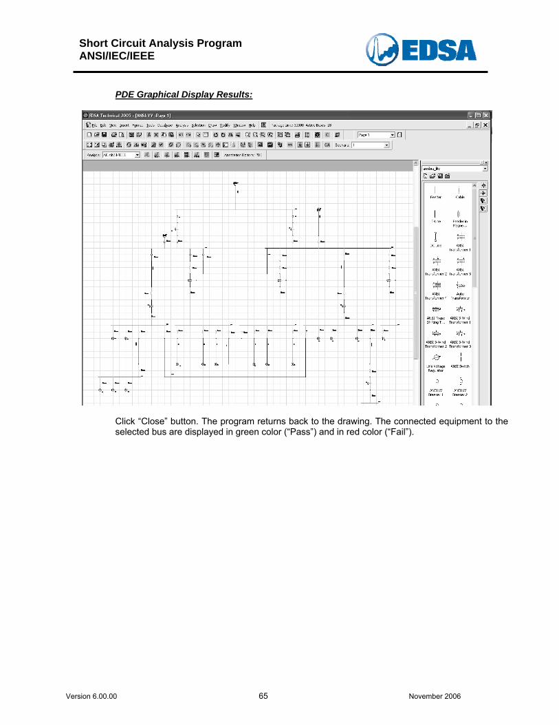
PDE Graphical Display Results:
Click “Close” button. The program returns back to the drawing. The connected equipment to the selected bus are displayed in green color (“Pass”) and in red color (“Fail”).
Short Circuit Analysis Program ANSI/IEC/IEEE
Version 6.00.00 66 November 2006
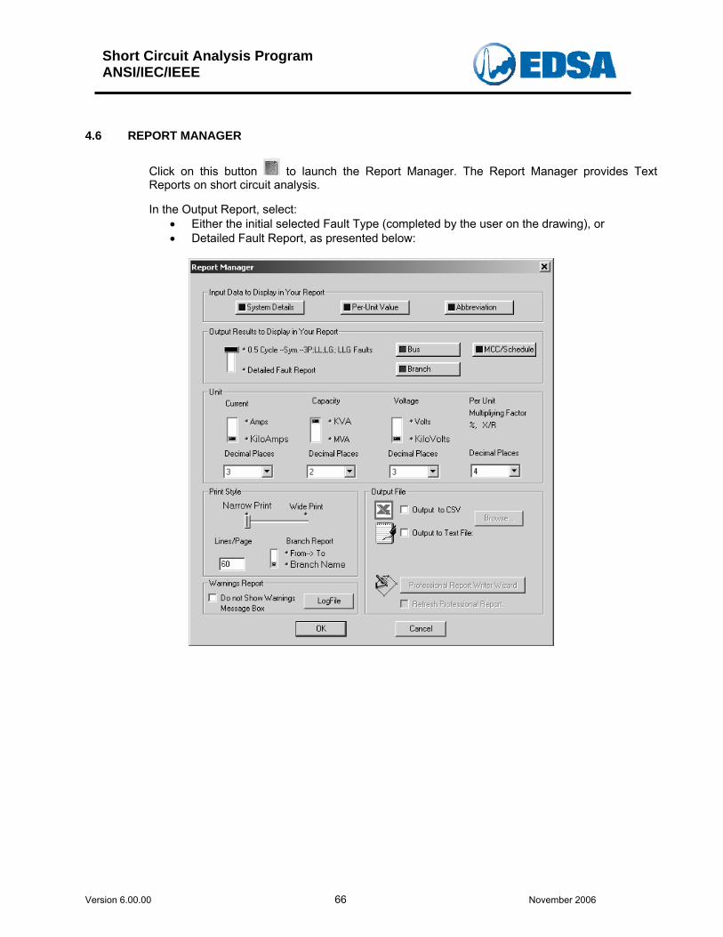
4.6 REPORT MANAGER
Click on this button to launch the Report Manager. The Report Manager provides Text Reports on short circuit analysis. In the Output Report, select:
• Either the initial selected Fault Type (completed by the user on the drawing), or • Detailed Fault Report, as presented below:
Short Circuit Analysis Program ANSI/IEC/IEEE
Version 6.00.00 67 November 2006
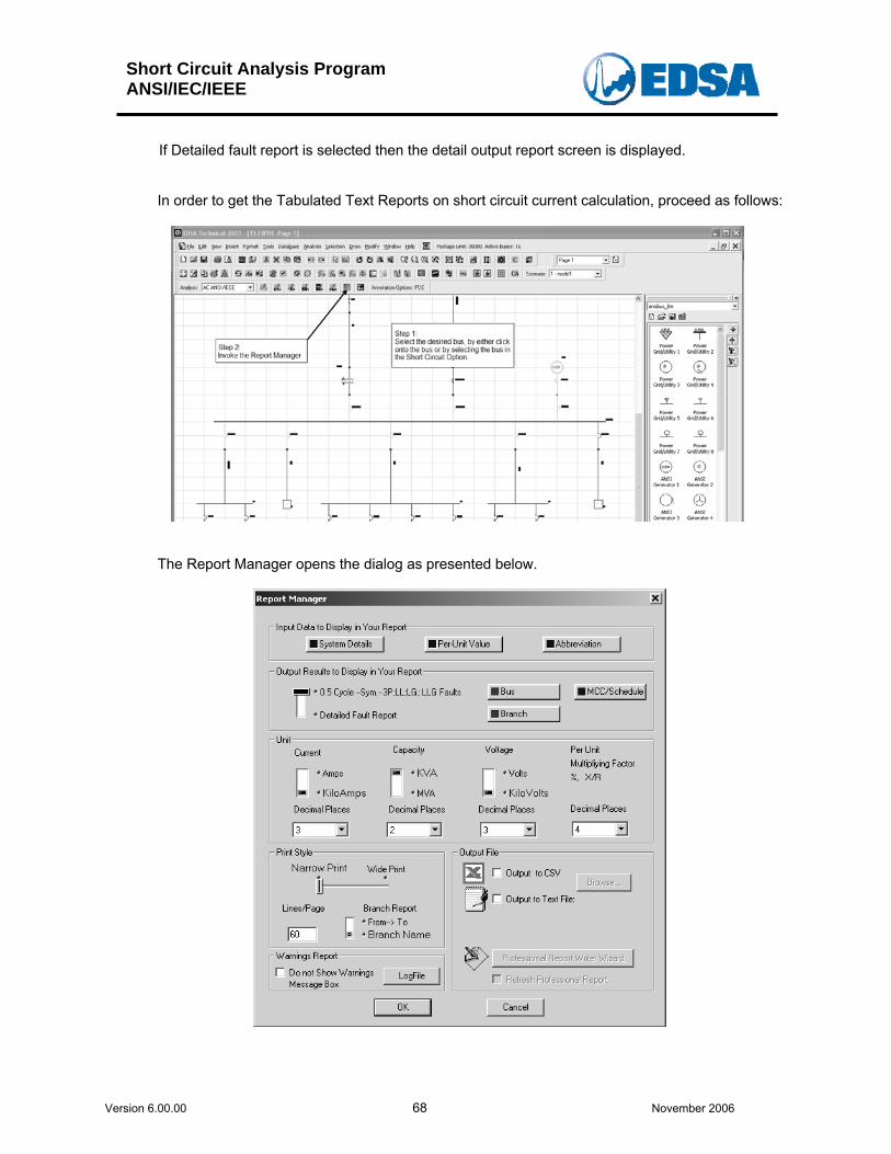
In the Report manager, the following outputs are available:
• Input data: o System Details; o Per-Unit value; o Abbreviation.
• Output file:
o CSV output file; o Output to Text File.
• Unit:
o Current; o Capacity; o Voltage.
• Decimal Places for:
o Current; o Capacity; o Voltage. o Per unit MF and %X/R
• Output Option:
o Bus; o Branch.
• Text Output Report:
o as per user selection fault type and instant of time, as presented above: 0.5 Cycle, symmetrical 3P,LL, LG, LLG Faults, or
o Detailed fault Report.
Short Circuit Analysis Program ANSI/IEC/IEEE
Version 6.00.00 68 November 2006
If Detailed fault report is selected then the detail output report screen is displayed.
In order to get the Tabulated Text Reports on short circuit current calculation, proceed as follows:
The Report Manager opens the dialog as presented below.
Short Circuit Analysis Program ANSI/IEC/IEEE
Version 6.00.00 69 November 2006
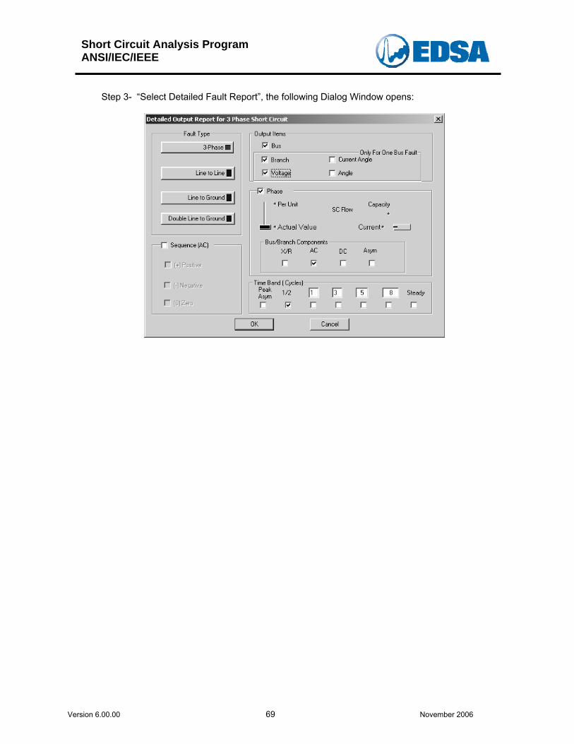
Step 3- “Select Detailed Fault Report”, the following Dialog Window opens:
Short Circuit Analysis Program ANSI/IEC/IEEE
Version 6.00.00 70 November 2006
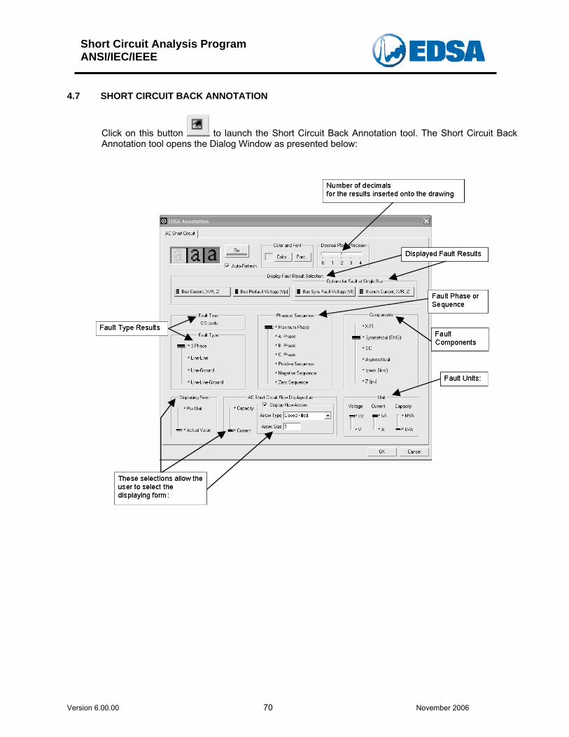
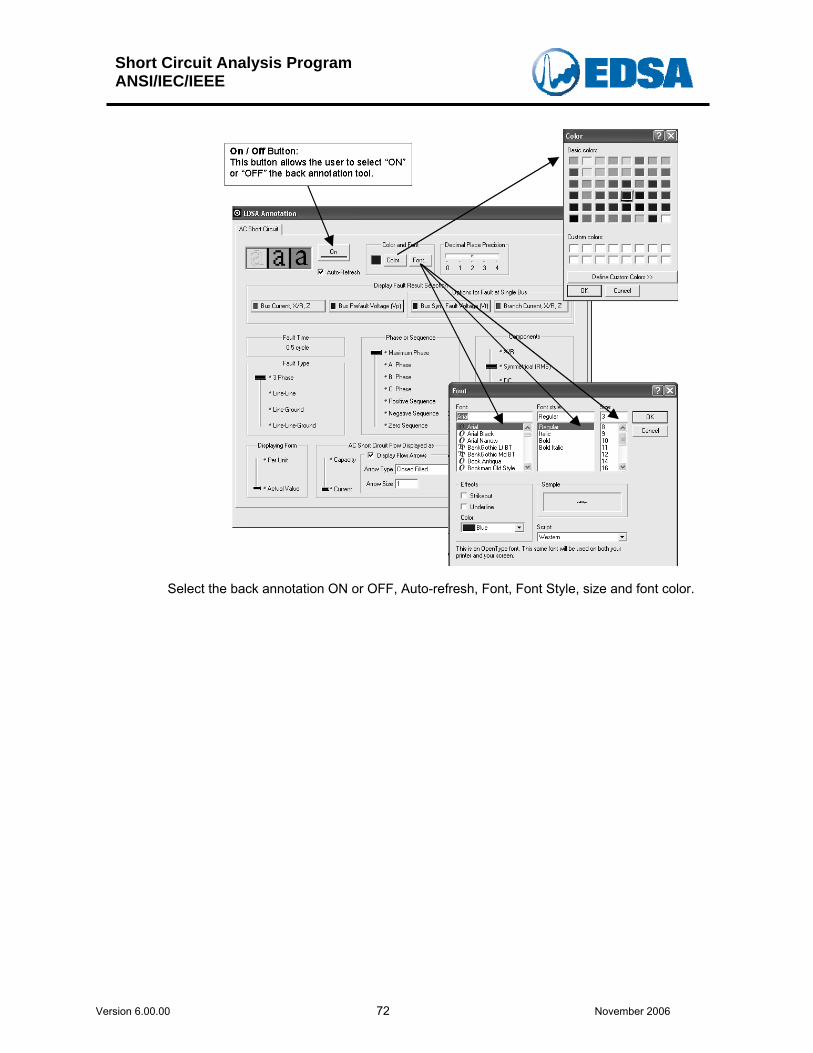
4.7 SHORT CIRCUIT BACK ANNOTATION
Click on this button to launch the Short Circuit Back Annotation tool. The Short Circuit Back Annotation tool opens the Dialog Window as presented below:
Short Circuit Analysis Program ANSI/IEC/IEEE
Version 6.00.00 71 November 2006
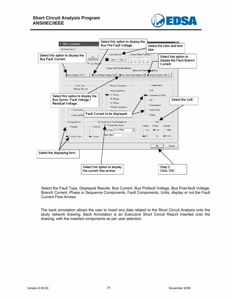
Select the Fault Type, Displayed Results: Bus Current, Bus Prefault Voltage, Bus Post-fault Voltage, Branch Current, Phase or Sequence Components, Fault Components, Units, display or not the Fault Current Flow Arrows.
The back annotation allows the user to insert any data related to the Short Circuit Analysis onto the study network drawing. Back Annotation is an Executive Short Circuit Report inserted onto the drawing, with the inserted components as per user selection.
Short Circuit Analysis Program ANSI/IEC/IEEE
Version 6.00.00 72 November 2006
Select the back annotation ON or OFF, Auto-refresh, Font, Font Style, size and font color.
Short Circuit Analysis Program ANSI/IEC/IEEE
Version 6.00.00 73 November 2006
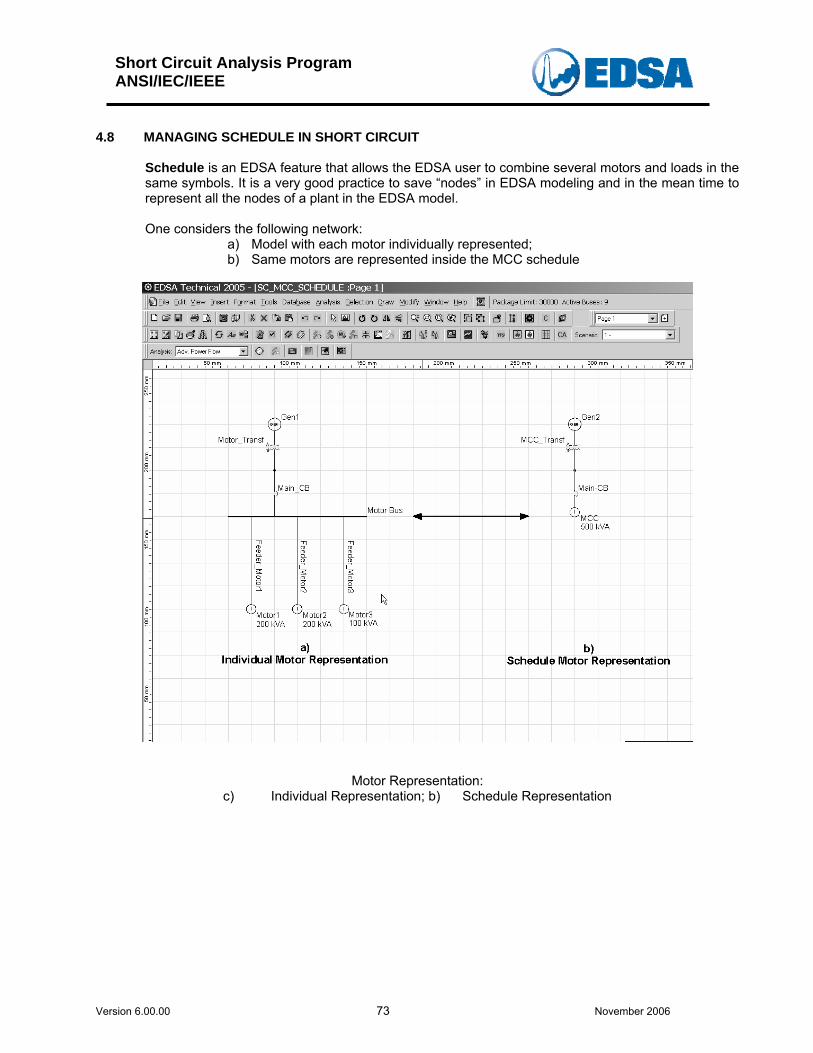
4.8 MANAGING SCHEDULE IN SHORT CIRCUIT
Schedule is an EDSA feature that allows the EDSA user to combine several motors and loads in the same symbols. It is a very good practice to save “nodes” in EDSA modeling and in the mean time to represent all the nodes of a plant in the EDSA model. One considers the following network:
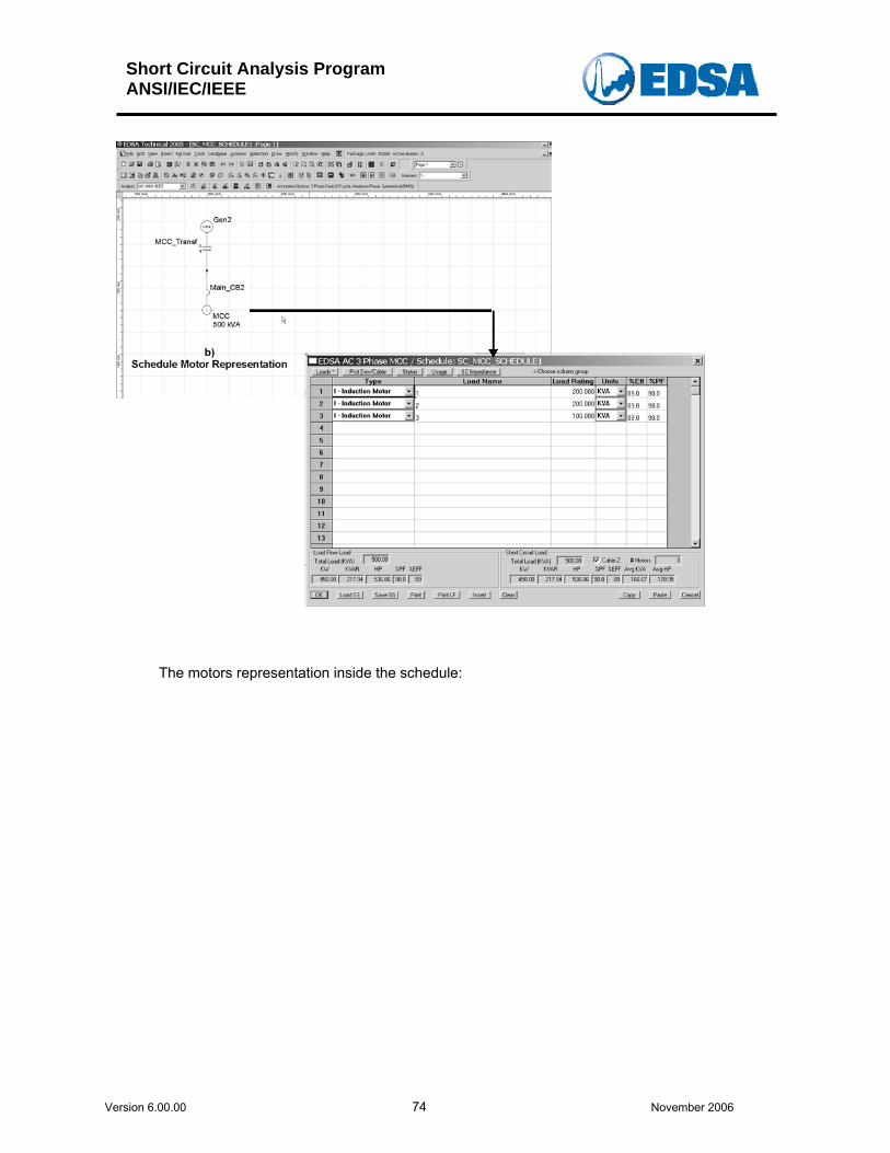
a) Model with each motor individually represented; b) Same motors are represented inside the MCC schedule
Motor Representation:
c) Individual Representation; b) Schedule Representation
Short Circuit Analysis Program ANSI/IEC/IEEE
Version 6.00.00 74 November 2006
The motors representation inside the schedule:
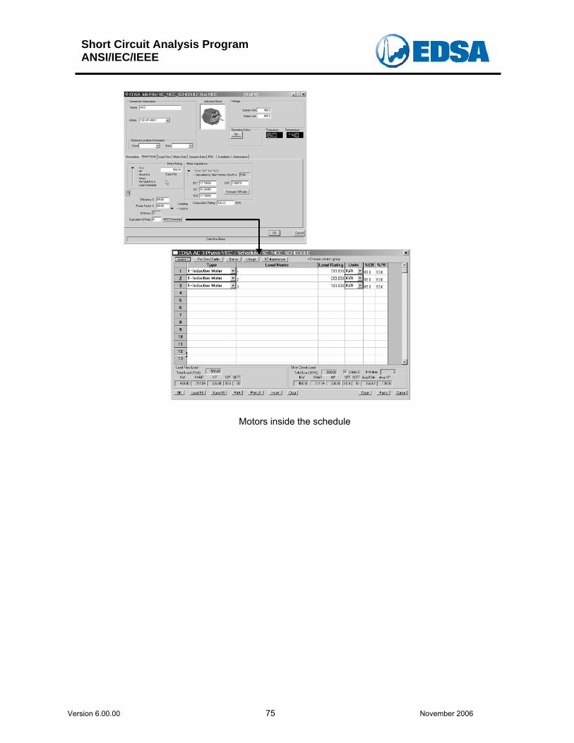
Short Circuit Analysis Program ANSI/IEC/IEEE
Version 6.00.00 75 November 2006
Motors inside the schedule
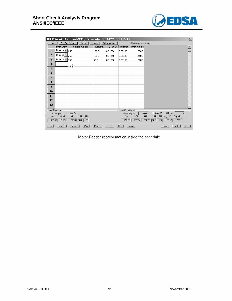
Short Circuit Analysis Program ANSI/IEC/IEEE
Version 6.00.00 76 November 2006
Motor Feeder representation inside the schedule
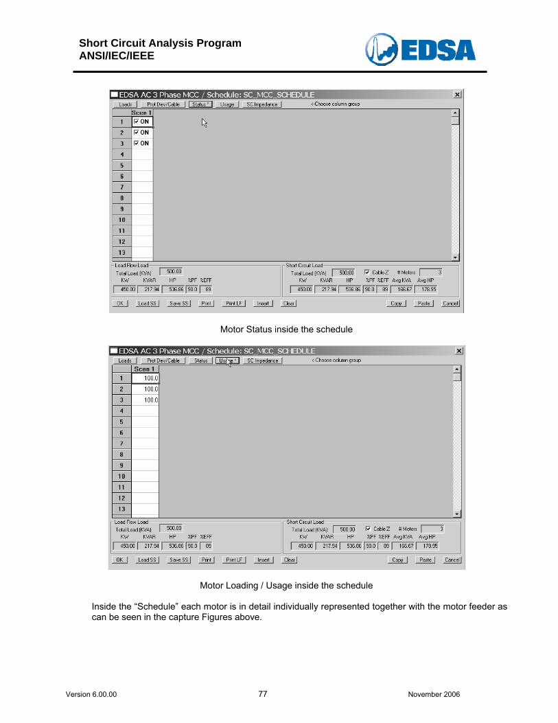
Short Circuit Analysis Program ANSI/IEC/IEEE
Version 6.00.00 77 November 2006
Motor Status inside the schedule
Motor Loading / Usage inside the schedule
Inside the “Schedule” each motor is in detail individually represented together with the motor feeder as can be seen in the capture Figures above.
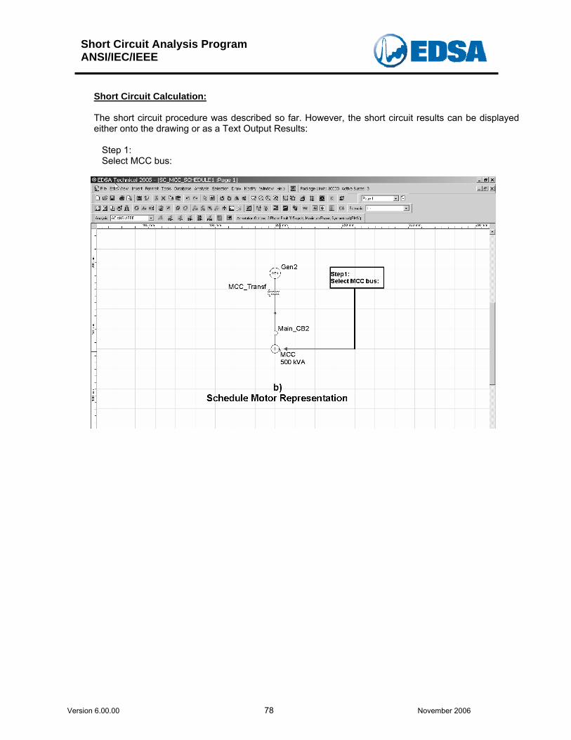
Short Circuit Analysis Program ANSI/IEC/IEEE
Version 6.00.00 78 November 2006
Short Circuit Calculation: The short circuit procedure was described so far. However, the short circuit results can be displayed either onto the drawing or as a Text Output Results:
Step 1: Select MCC bus:
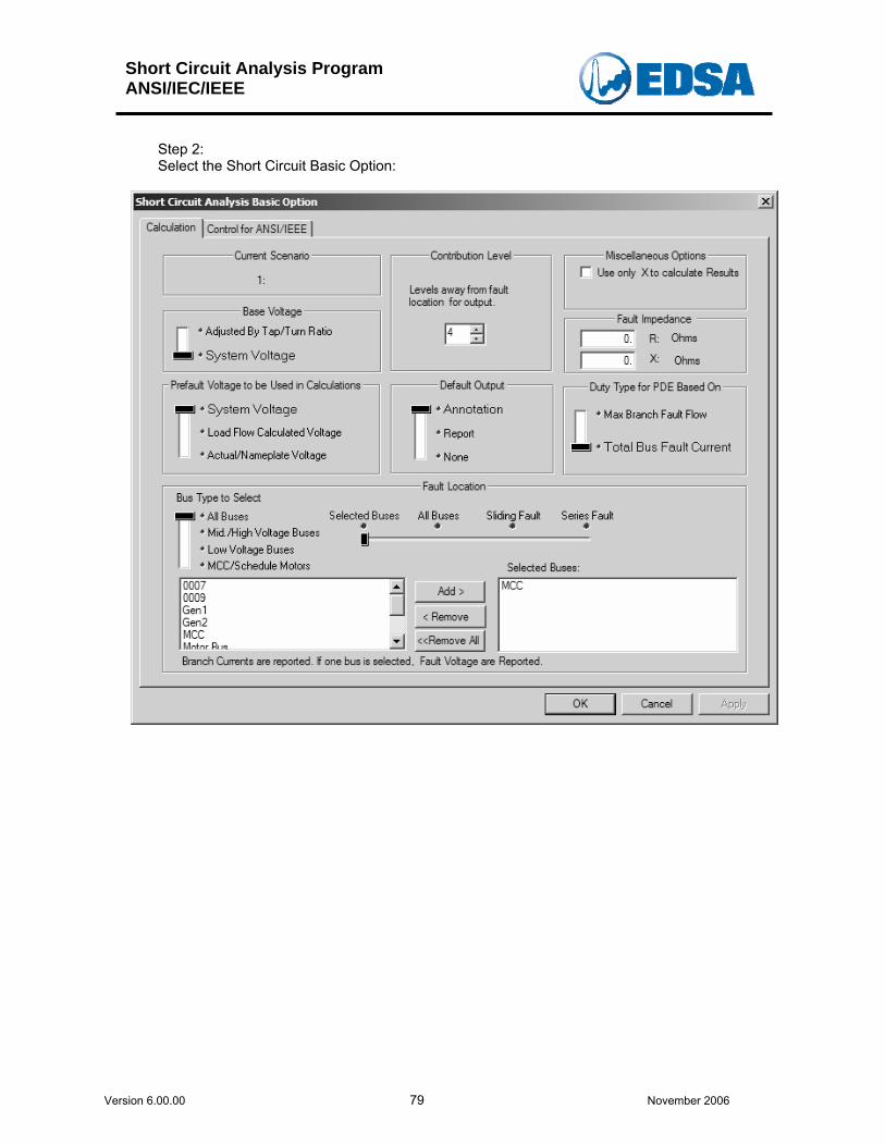
Short Circuit Analysis Program ANSI/IEC/IEEE
Version 6.00.00 79 November 2006
Step 2: Select the Short Circuit Basic Option:
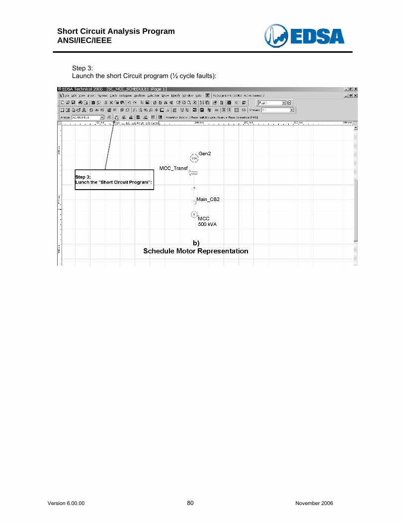
Short Circuit Analysis Program ANSI/IEC/IEEE
Version 6.00.00 80 November 2006
Step 3: Launch the short Circuit program (½ cycle faults):
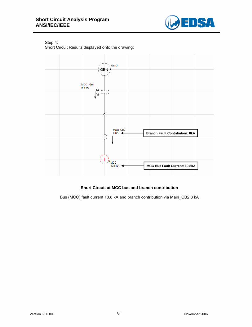
Short Circuit Analysis Program ANSI/IEC/IEEE
Version 6.00.00 81 November 2006
Step 4: Short Circuit Results displayed onto the drawing:
Branch Fault Contribution: 8kA
MCC Bus Fault Current: 10.8kA
Short Circuit at MCC bus and branch contribution
Bus (MCC) fault current 10.8 kA and branch contribution via Main_CB2 8 kA
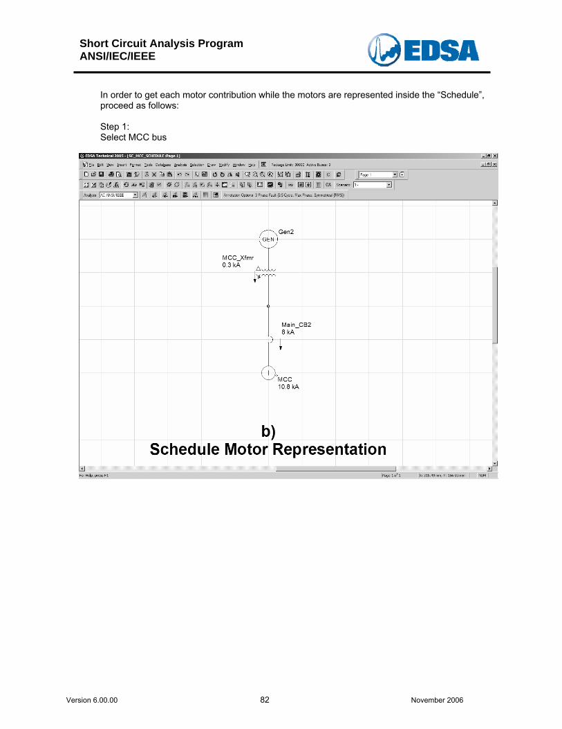
Short Circuit Analysis Program ANSI/IEC/IEEE
Version 6.00.00 82 November 2006
In order to get each motor contribution while the motors are represented inside the “Schedule”, proceed as follows: Step 1: Select MCC bus
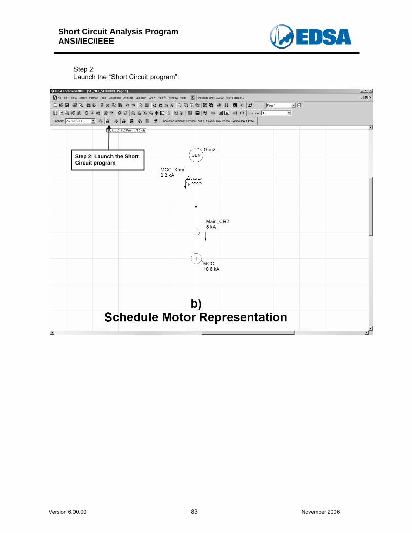
Short Circuit Analysis Program ANSI/IEC/IEEE
Version 6.00.00 83 November 2006
Step 2: Launch the “Short Circuit program”:
Step 2: Launch the Short Circuit program
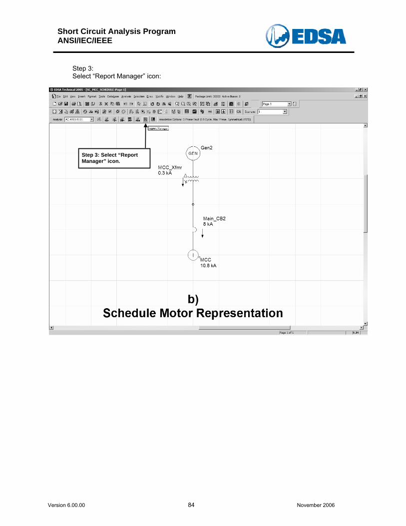
Short Circuit Analysis Program ANSI/IEC/IEEE
Version 6.00.00 84 November 2006
Step 3: Select “Report Manager” icon:
Step 3: Select “Report Manager” icon.
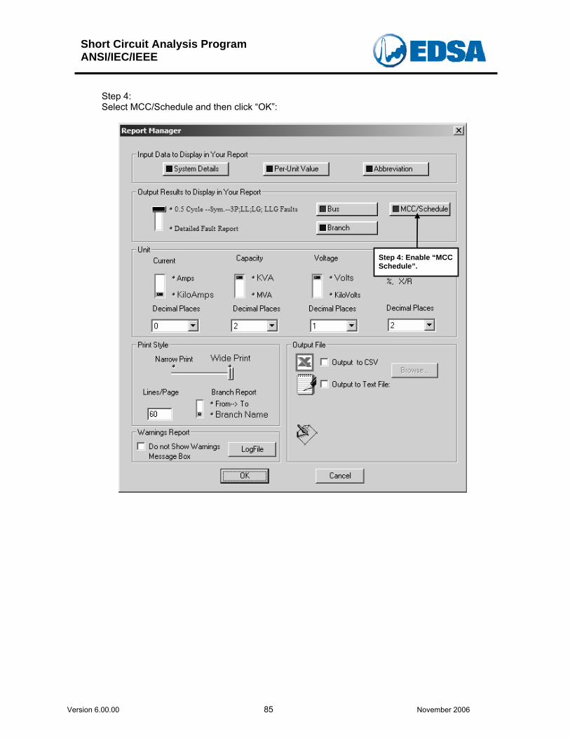
Short Circuit Analysis Program ANSI/IEC/IEEE
Version 6.00.00 85 November 2006
Step 4: Select MCC/Schedule and then click “OK”:
Step 4: Enable “MCC Schedule”.
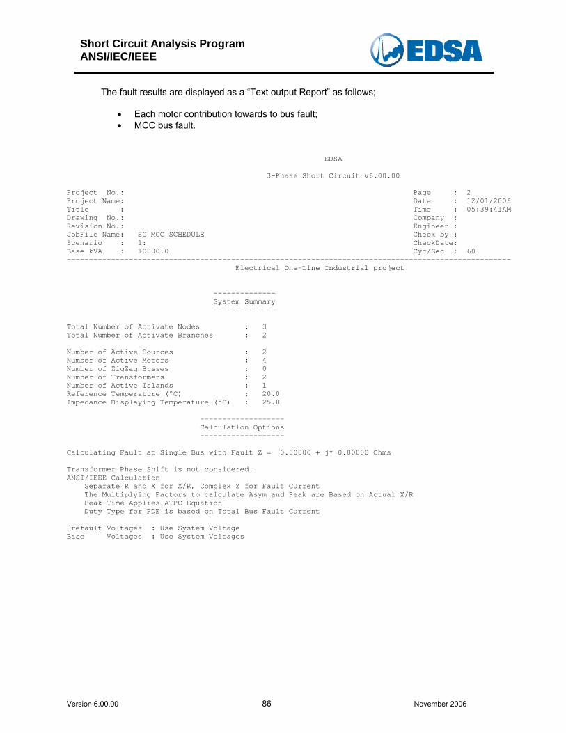
Short Circuit Analysis Program ANSI/IEC/IEEE
Version 6.00.00 86 November 2006
The fault results are displayed as a “Text output Report” as follows;
• Each motor contribution towards to bus fault; • MCC bus fault.
EDSA 3-Phase Short Circuit v6.00.00 Project No.: Page : 2 Project Name: Date : 12/01/2006 Title : Time : 05:39:41AM Drawing No.: Company : Revision No.: Engineer : JobFile Name: SC_MCC_SCHEDULE Check by : Scenario : 1: CheckDate: Base kVA : 10000.0 Cyc/Sec : 60 ---------------------------------------------------------------------------------------------------- Electrical One-Line Industrial project -------------- System Summary -------------- Total Number of Activate Nodes : 3 Total Number of Activate Branches : 2 Number of Active Sources : 2 Number of Active Motors : 4 Number of ZigZag Busses : 0 Number of Transformers : 2 Number of Active Islands : 1 Reference Temperature (°C) : 20.0 Impedance Displaying Temperature (°C) : 25.0 ------------------- Calculation Options ------------------- Calculating Fault at Single Bus with Fault Z = 0.00000 + j* 0.00000 Ohms Transformer Phase Shift is not considered. ANSI/IEEE Calculation Separate R and X for X/R, Complex Z for Fault Current The Multiplying Factors to calculate Asym and Peak are Based on Actual X/R Peak Time Applies ATPC Equation Duty Type for PDE is based on Total Bus Fault Current Prefault Voltages : Use System Voltage Base Voltages : Use System Voltages
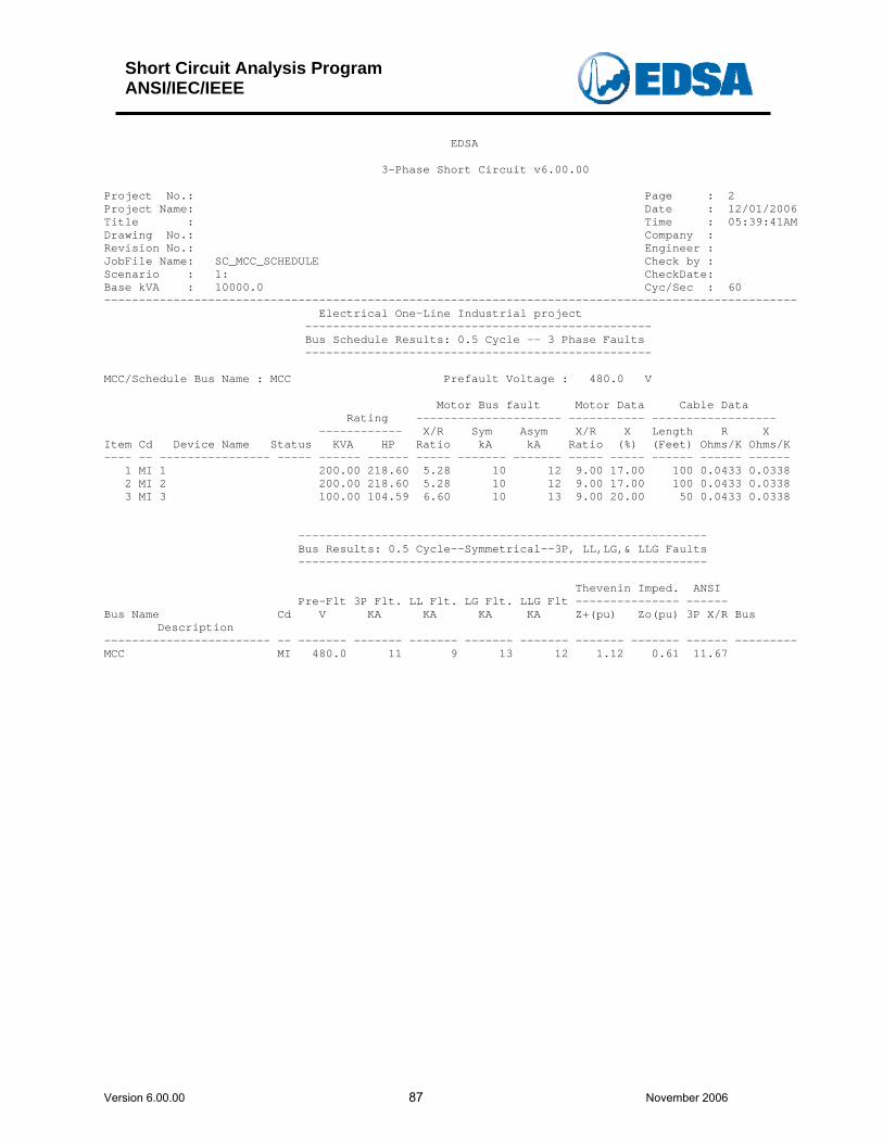
Short Circuit Analysis Program ANSI/IEC/IEEE
Version 6.00.00 87 November 2006
EDSA 3-Phase Short Circuit v6.00.00 Project No.: Page : 2 Project Name: Date : 12/01/2006 Title : Time : 05:39:41AM Drawing No.: Company : Revision No.: Engineer : JobFile Name: SC_MCC_SCHEDULE Check by : Scenario : 1: CheckDate: Base kVA : 10000.0 Cyc/Sec : 60 ---------------------------------------------------------------------------------------------------- Electrical One-Line Industrial project -------------------------------------------------- Bus Schedule Results: 0.5 Cycle -- 3 Phase Faults -------------------------------------------------- MCC/Schedule Bus Name : MCC Prefault Voltage : 480.0 V Motor Bus fault Motor Data Cable Data Rating --------------------- ----------- ------------------ ------------ X/R Sym Asym X/R X Length R X Item Cd Device Name Status KVA HP Ratio kA kA Ratio (%) (Feet) Ohms/K Ohms/K ---- -- ---------------- ----- ------ ------ ----- ------- ------- ----- ----- ------ ------ ------ 1 MI 1 200.00 218.60 5.28 10 12 9.00 17.00 100 0.0433 0.0338 2 MI 2 200.00 218.60 5.28 10 12 9.00 17.00 100 0.0433 0.0338 3 MI 3 100.00 104.59 6.60 10 13 9.00 20.00 50 0.0433 0.0338 ----------------------------------------------------------- Bus Results: 0.5 Cycle--Symmetrical--3P, LL,LG,& LLG Faults ----------------------------------------------------------- Thevenin Imped. ANSI Pre-Flt 3P Flt. LL Flt. LG Flt. LLG Flt --------------- ------ Bus Name Cd V KA KA KA KA Z+(pu) Zo(pu) 3P X/R Bus
Description ------------------------ -- ------- ------- ------- ------- ------- ------- ------- ------ --------- MCC MI 480.0 11 9 13 12 1.12 0.61 11.67
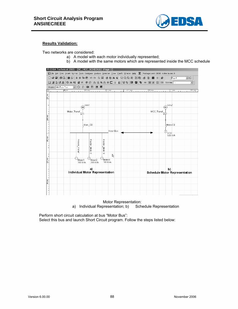
Short Circuit Analysis Program ANSI/IEC/IEEE
Version 6.00.00 88 November 2006
Results Validation: Two networks are considered:
a) A model with each motor individually represented; b) A model with the same motors which are represented inside the MCC schedule
Motor Representation: a) Individual Representation; b) Schedule Representation
Perform short circuit calculation at bus “Motor Bus”: Select this bus and launch Short Circuit program. Follow the steps listed below:
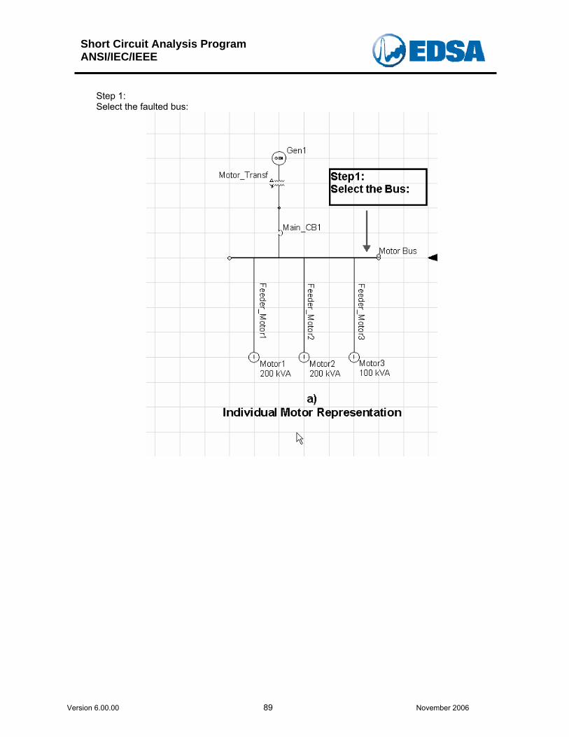
Short Circuit Analysis Program ANSI/IEC/IEEE
Version 6.00.00 89 November 2006
Step 1: Select the faulted bus:

Short Circuit Analysis Program ANSI/IEC/IEEE
Version 6.00.00 90 November 2006
Step 2: Select the Short Circuit Icon:
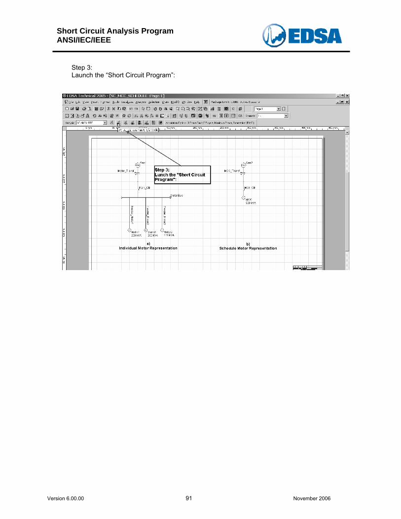
Short Circuit Analysis Program ANSI/IEC/IEEE
Version 6.00.00 91 November 2006
Step 3: Launch the “Short Circuit Program”:
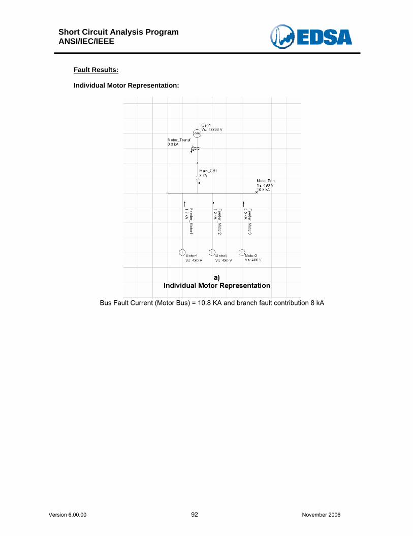
Short Circuit Analysis Program ANSI/IEC/IEEE
Version 6.00.00 92 November 2006
Fault Results: Individual Motor Representation:
Bus Fault Current (Motor Bus) = 10.8 KA and branch fault contribution 8 kA
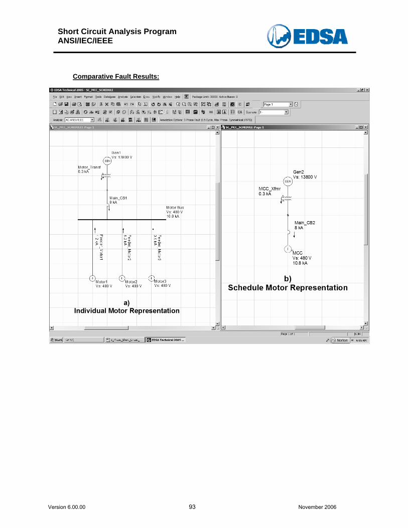
Short Circuit Analysis Program ANSI/IEC/IEEE
Version 6.00.00 93 November 2006
Comparative Fault Results:
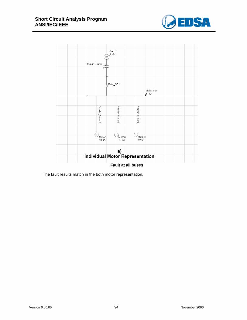
Short Circuit Analysis Program ANSI/IEC/IEEE
Version 6.00.00 94 November 2006
Fault at all buses
The fault results match in the both motor representation.
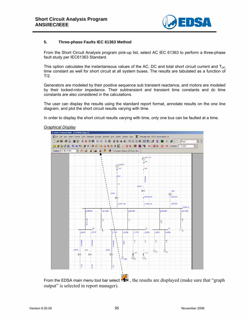
Short Circuit Analysis Program ANSI/IEC/IEEE
Version 6.00.00 95 November 2006
5. Three-phase Faults IEC 61363 Method
From the Short Circuit Analysis program pick-up list, select AC IEC 61363 to perform a three-phase fault study per IEC61363 Standard. This option calculates the instantaneous values of the AC, DC and total short circuit current and TDC time constant as well for short circuit at all system buses. The results are tabulated as a function of T/2.
Generators are modeled by their positive sequence sub transient reactance, and motors are modeled by their locked-rotor impedance. Their subtransient and transient time constants and dc time constants are also considered in the calculations. The user can display the results using the standard report format, annotate results on the one line diagram, and plot the short circuit results varying with time. In order to display the short circuit results varying with time, only one bus can be faulted at a time. Graphical Display
From the EDSA main menu tool bar select , the results are displayed (make sure that “graph output” is selected in report manager).
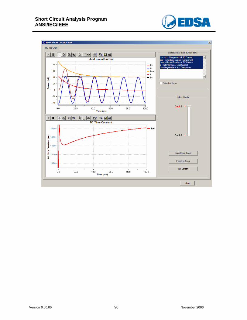
Short Circuit Analysis Program ANSI/IEC/IEEE
Version 6.00.00 96 November 2006
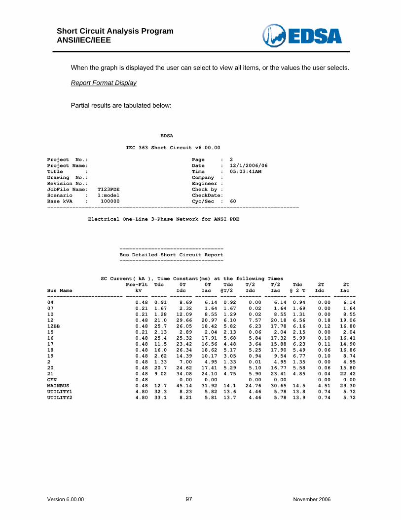
Short Circuit Analysis Program ANSI/IEC/IEEE
Version 6.00.00 97 November 2006
When the graph is displayed the user can select to view all items, or the values the user selects. Report Format Display Partial results are tabulated below:
EDSA IEC 363 Short Circuit v6.00.00 Project No.: Page : 2 Project Name: Date : 12/1/2006/06 Title : Time : 05:03:41AM Drawing No.: Company : Revision No.: Engineer : JobFile Name: T123PDE Check by : Scenario : 1:mode1 CheckDate: Base kVA : 100000 Cyc/Sec : 60 -------------------------------------------------------------------------------- Electrical One-Line 3-Phase Network for ANSI PDE --------------------------------- Bus Detailed Short Circuit Report --------------------------------- SC Current( kA ), Time Constant(ms) at the following Times Pre-Flt Tdc 0T 0T Tdc T/2 T/2 Tdc 2T 2T Bus Name kV Idc Iac @T/2 Idc Iac @ 2 T Idc Iac ------------------------ ------- ----- ------- ------- ----- ------- ------- ----- ------- ------- 04 0.48 0.91 8.69 6.14 0.92 0.00 6.14 0.94 0.00 6.14 07 0.21 1.67 2.32 1.64 1.67 0.02 1.64 1.69 0.00 1.64 10 0.21 1.28 12.09 8.55 1.29 0.02 8.55 1.31 0.00 8.55 12 0.48 21.0 29.66 20.97 6.10 7.57 20.18 6.56 0.18 19.06 12BB 0.48 25.7 26.05 18.42 5.82 6.23 17.78 6.16 0.12 16.80 15 0.21 2.13 2.89 2.04 2.13 0.06 2.04 2.15 0.00 2.04 16 0.48 25.4 25.32 17.91 5.68 5.84 17.32 5.99 0.10 16.41 17 0.48 11.5 23.42 16.56 4.48 3.64 15.88 6.23 0.11 14.90 18 0.48 16.0 26.34 18.62 5.17 5.25 17.90 5.49 0.06 16.86 19 0.48 2.62 14.39 10.17 3.05 0.94 9.54 6.77 0.10 8.74 2 0.48 1.33 7.00 4.95 1.33 0.01 4.95 1.35 0.00 4.95 20 0.48 20.7 24.62 17.41 5.29 5.10 16.77 5.58 0.06 15.80 21 0.48 9.02 34.08 24.10 4.75 5.90 23.41 4.85 0.04 22.42 GEN 0.48 0.00 0.00 0.00 0.00 0.00 0.00 MAINBUS 0.48 12.7 45.14 31.92 14.1 24.76 30.65 14.5 4.51 29.30 UTILITY1 4.80 32.3 8.23 5.82 13.6 4.46 5.78 13.8 0.74 5.72 UTILITY2 4.80 33.1 8.21 5.81 13.7 4.46 5.78 13.9 0.74 5.72
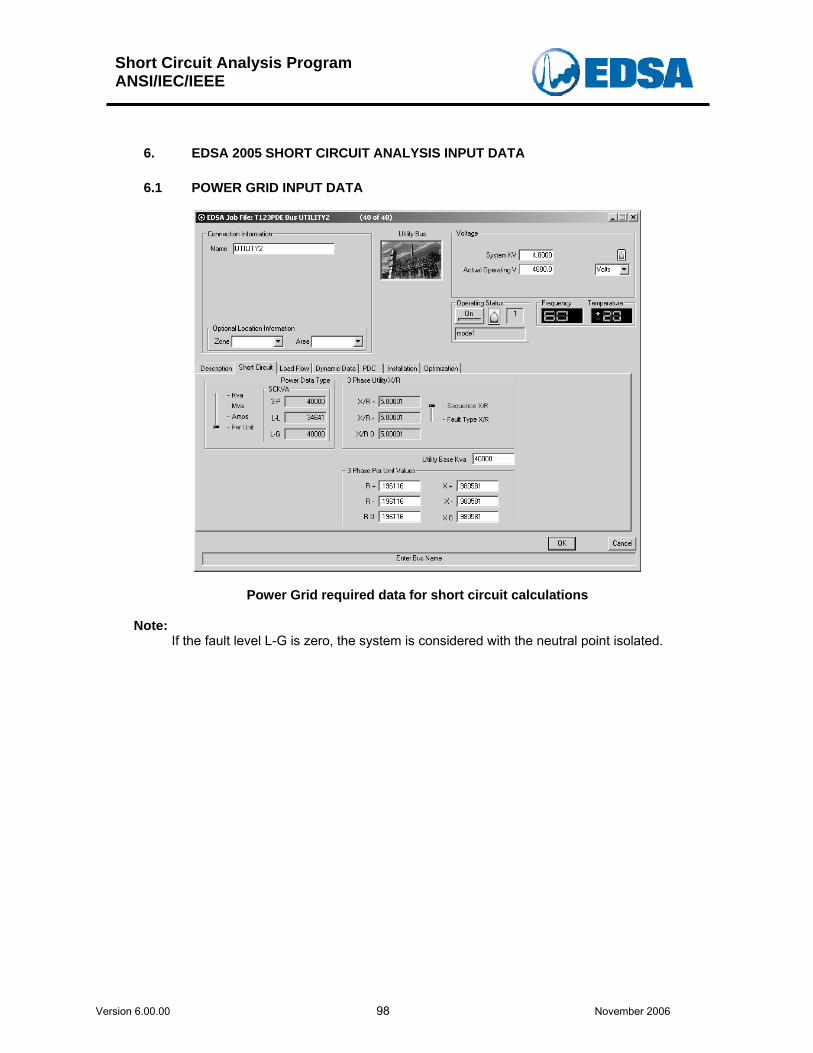
Short Circuit Analysis Program ANSI/IEC/IEEE
Version 6.00.00 98 November 2006
6. EDSA 2005 SHORT CIRCUIT ANALYSIS INPUT DATA 6.1 POWER GRID INPUT DATA
Power Grid required data for short circuit calculations
Note: If the fault level L-G is zero, the system is considered with the neutral point isolated.
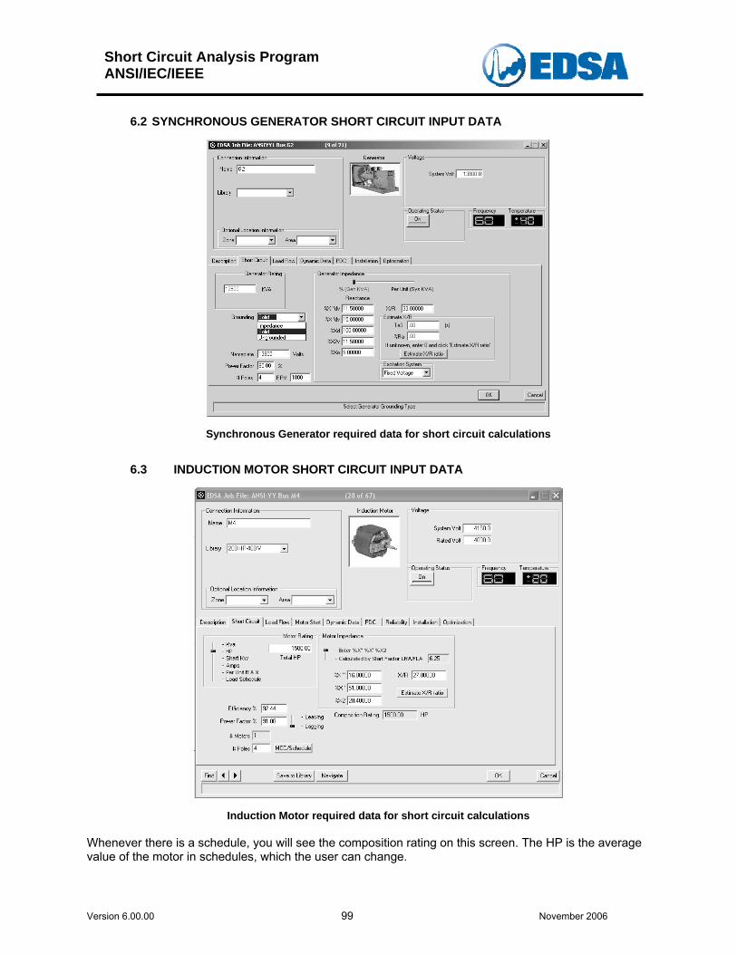
Short Circuit Analysis Program ANSI/IEC/IEEE
Version 6.00.00 99 November 2006
6.2 SYNCHRONOUS GENERATOR SHORT CIRCUIT INPUT DATA
Synchronous Generator required data for short circuit calculations
6.3 INDUCTION MOTOR SHORT CIRCUIT INPUT DATA
Induction Motor required data for short circuit calculations Whenever there is a schedule, you will see the composition rating on this screen. The HP is the average value of the motor in schedules, which the user can change.
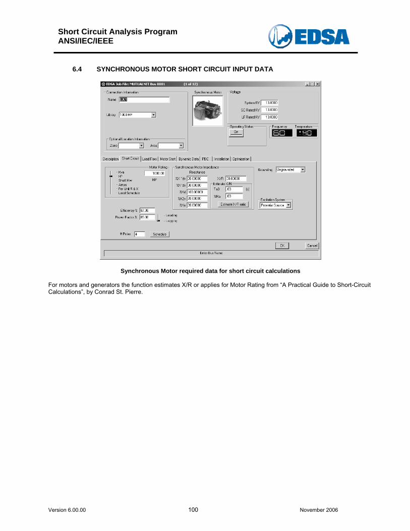
Short Circuit Analysis Program ANSI/IEC/IEEE
Version 6.00.00 100 November 2006
6.4 SYNCHRONOUS MOTOR SHORT CIRCUIT INPUT DATA
Synchronous Motor required data for short circuit calculations For motors and generators the function estimates X/R or applies for Motor Rating from “A Practical Guide to Short-Circuit Calculations”, by Conrad St. Pierre.
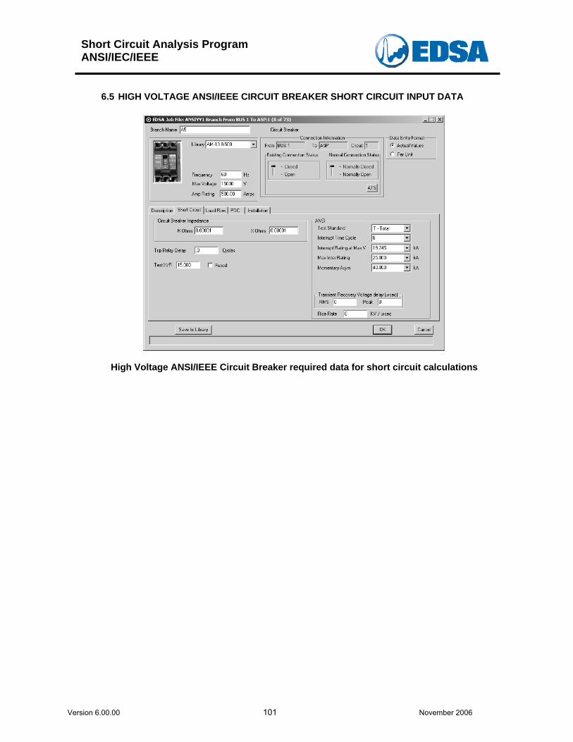
Short Circuit Analysis Program ANSI/IEC/IEEE
Version 6.00.00 101 November 2006
6.5 HIGH VOLTAGE ANSI/IEEE CIRCUIT BREAKER SHORT CIRCUIT INPUT DATA
High Voltage ANSI/IEEE Circuit Breaker required data for short circuit calculations
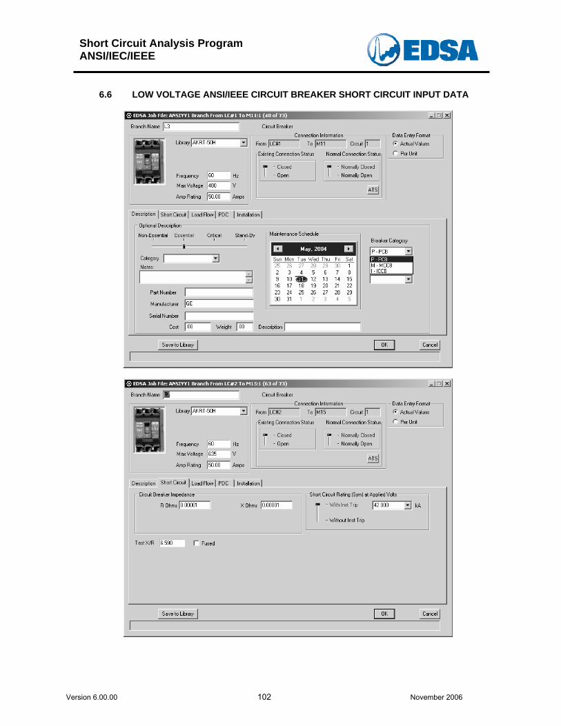
Short Circuit Analysis Program ANSI/IEC/IEEE
Version 6.00.00 102 November 2006
6.6 LOW VOLTAGE ANSI/IEEE CIRCUIT BREAKER SHORT CIRCUIT INPUT DATA
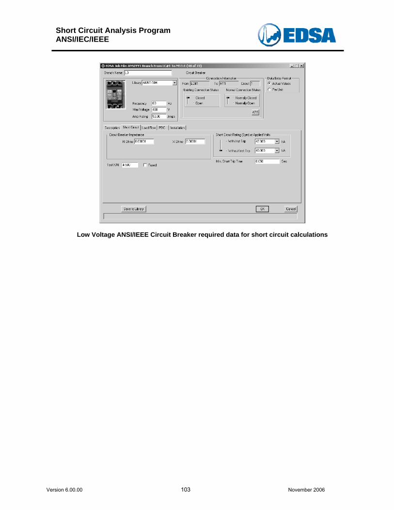
Short Circuit Analysis Program ANSI/IEC/IEEE
Version 6.00.00 103 November 2006
Low Voltage ANSI/IEEE Circuit Breaker required data for short circuit calculations
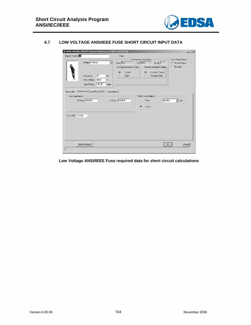
Short Circuit Analysis Program ANSI/IEC/IEEE
Version 6.00.00 104 November 2006
6.7 LOW VOLTAGE ANSI/IEEE FUSE SHORT CIRCUIT INPUT DATA
Low Voltage ANSI/IEEE Fuse required data for short circuit calculations
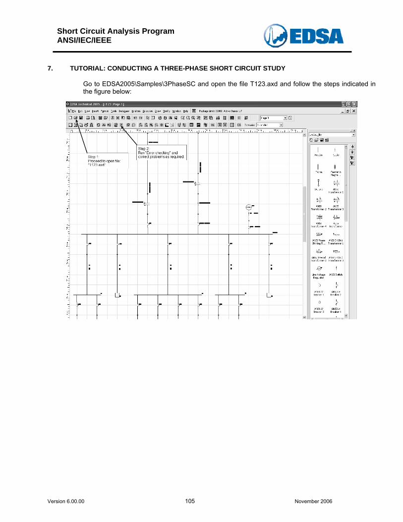
Short Circuit Analysis Program ANSI/IEC/IEEE
Version 6.00.00 105 November 2006
7. TUTORIAL: CONDUCTING A THREE-PHASE SHORT CIRCUIT STUDY Go to EDSA2005\Samples\3PhaseSC and open the file T123.axd and follow the steps indicated in the figure below:
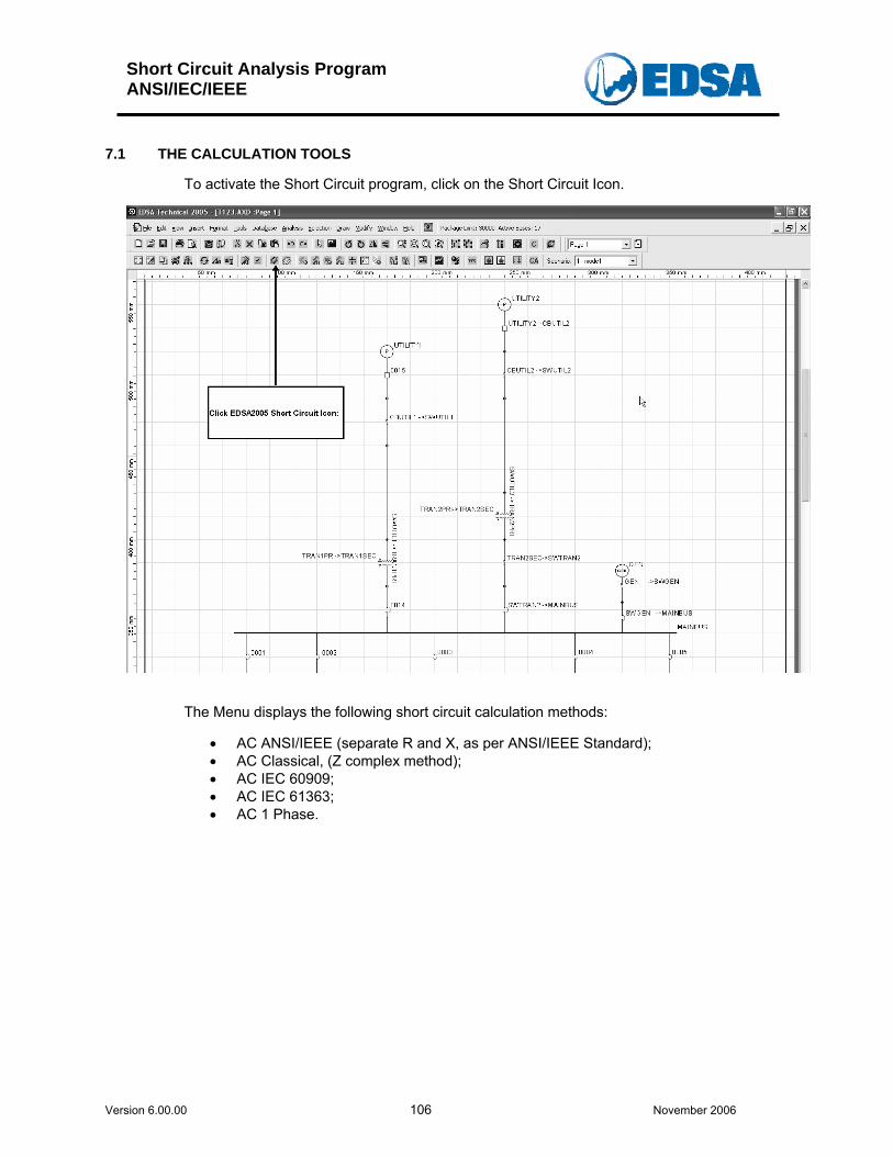
Short Circuit Analysis Program ANSI/IEC/IEEE
Version 6.00.00 106 November 2006
7.1 THE CALCULATION TOOLS
To activate the Short Circuit program, click on the Short Circuit Icon.
The Menu displays the following short circuit calculation methods:
• AC ANSI/IEEE (separate R and X, as per ANSI/IEEE Standard); • AC Classical, (Z complex method); • AC IEC 60909; • AC IEC 61363; • AC 1 Phase.
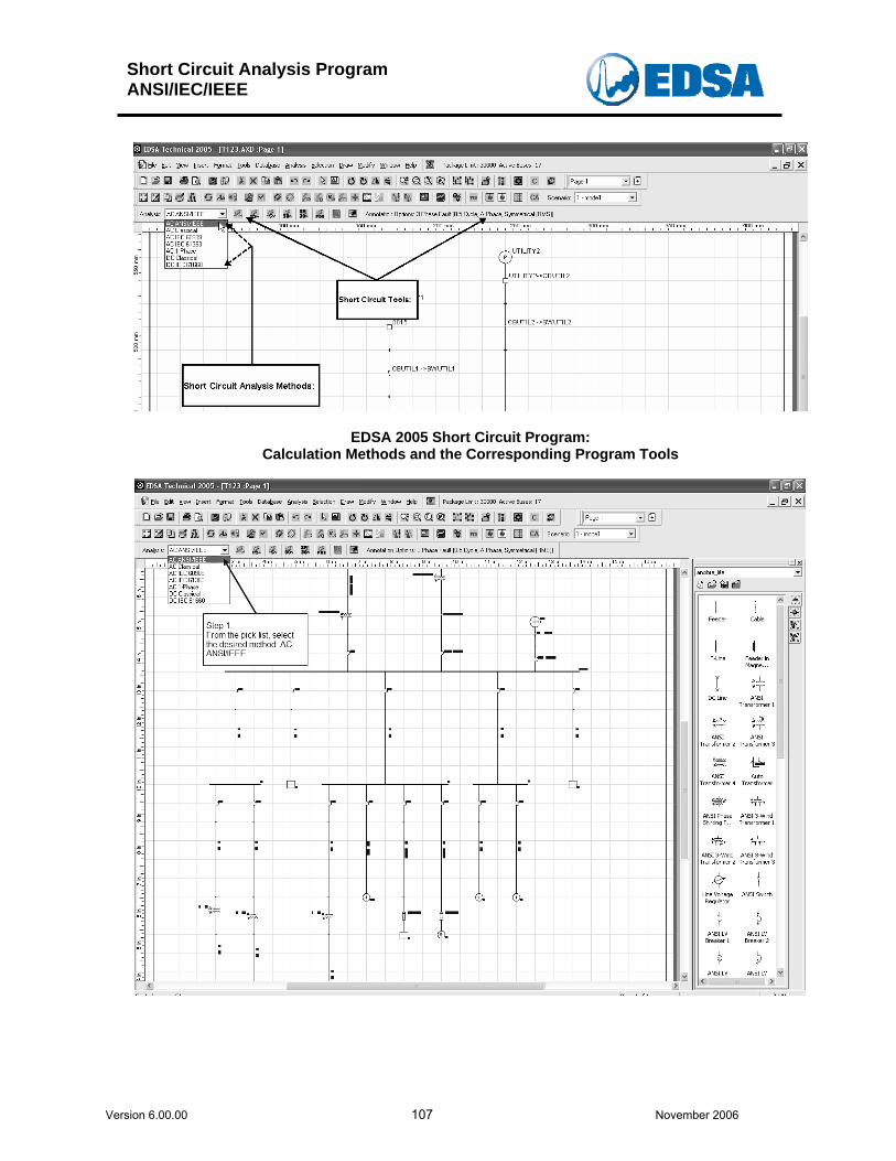
Short Circuit Analysis Program ANSI/IEC/IEEE
Version 6.00.00 107 November 2006
EDSA 2005 Short Circuit Program: Calculation Methods and the Corresponding Program Tools
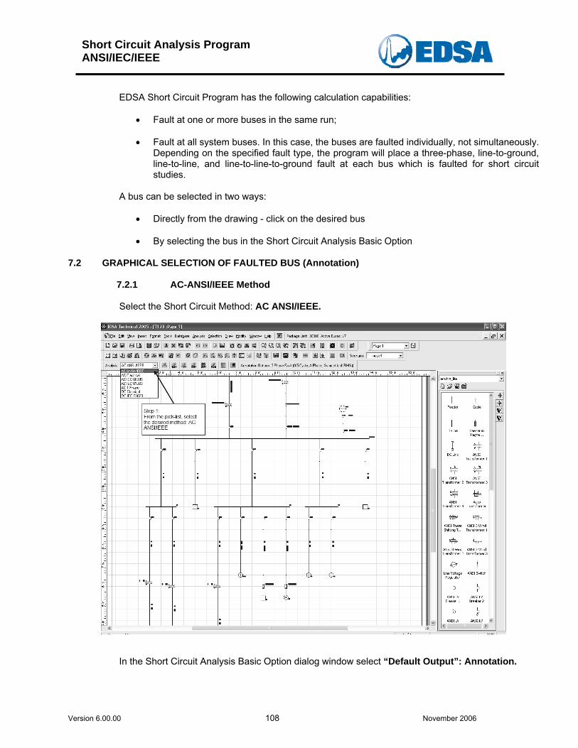
Short Circuit Analysis Program ANSI/IEC/IEEE
Version 6.00.00 108 November 2006
EDSA Short Circuit Program has the following calculation capabilities:
• Fault at one or more buses in the same run; • Fault at all system buses. In this case, the buses are faulted individually, not simultaneously.
Depending on the specified fault type, the program will place a three-phase, line-to-ground, line-to-line, and line-to-line-to-ground fault at each bus which is faulted for short circuit studies.
A bus can be selected in two ways:
• Directly from the drawing - click on the desired bus • By selecting the bus in the Short Circuit Analysis Basic Option
7.2 GRAPHICAL SELECTION OF FAULTED BUS (Annotation)
7.2.1 AC-ANSI/IEEE Method Select the Short Circuit Method: AC ANSI/IEEE.
In the Short Circuit Analysis Basic Option dialog window select “Default Output”: Annotation.
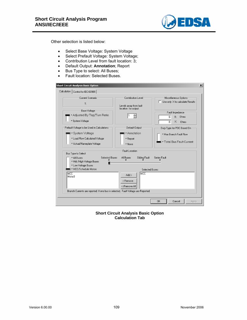
Short Circuit Analysis Program ANSI/IEC/IEEE
Version 6.00.00 109 November 2006
Other selection is listed below:
• Select Base Voltage: System Voltage • Select Prefault Voltage: System Voltage; • Contribution Level from fault location: 3; • Default Output: Annotation; Report • Bus Type to select: All Buses; • Fault location: Selected Buses.
Short Circuit Analysis Basic Option Calculation Tab
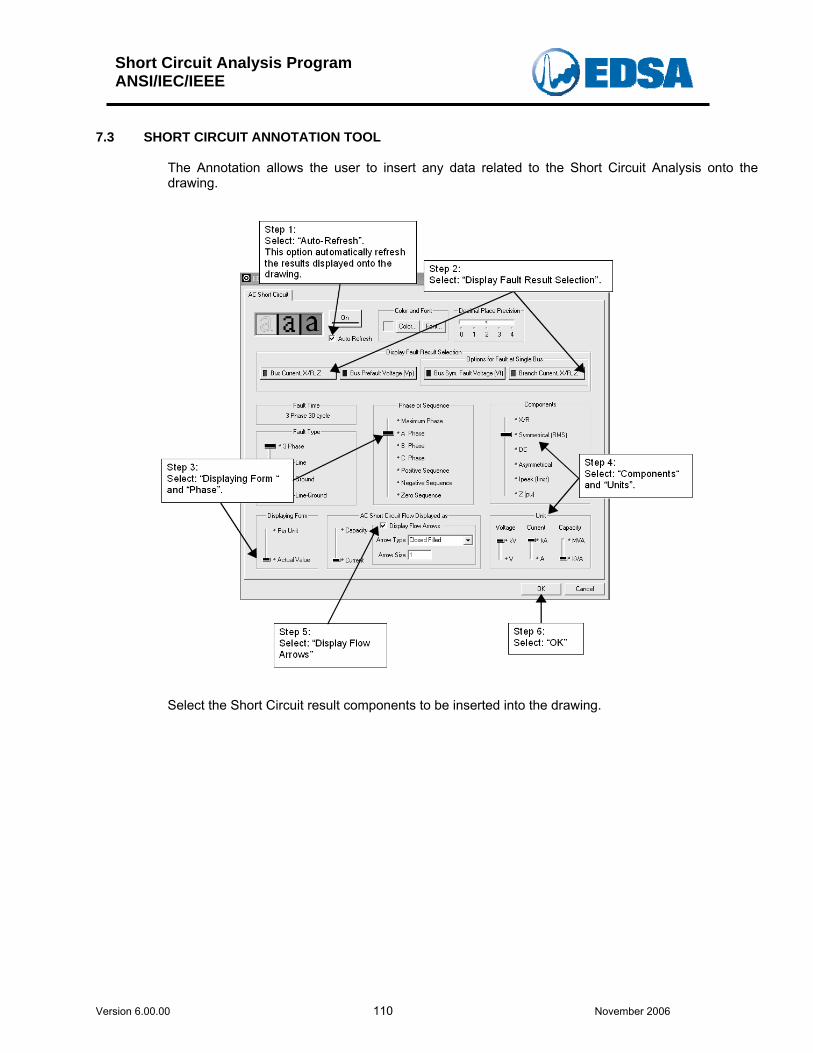
Short Circuit Analysis Program ANSI/IEC/IEEE
Version 6.00.00 110 November 2006
7.3 SHORT CIRCUIT ANNOTATION TOOL
The Annotation allows the user to insert any data related to the Short Circuit Analysis onto the drawing.
Select the Short Circuit result components to be inserted into the drawing.
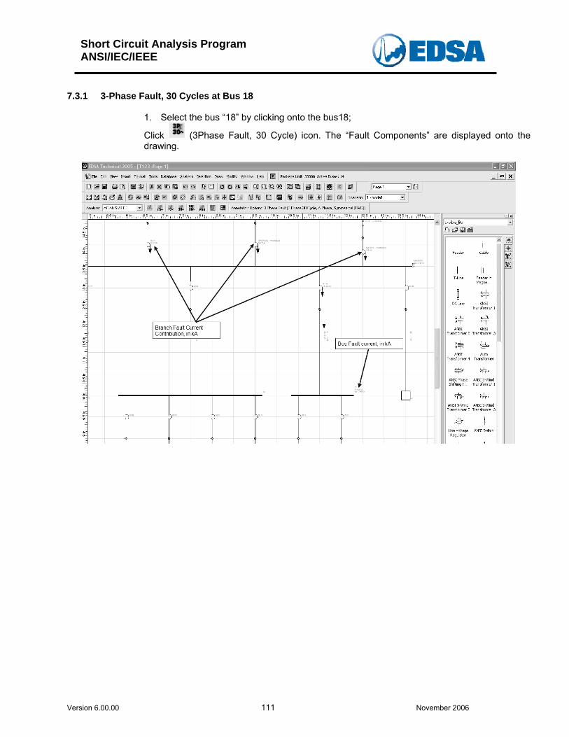
Short Circuit Analysis Program ANSI/IEC/IEEE
Version 6.00.00 111 November 2006
7.3.1 3-Phase Fault, 30 Cycles at Bus 18
1. Select the bus “18” by clicking onto the bus18;
Click (3Phase Fault, 30 Cycle) icon. The “Fault Components” are displayed onto the drawing.
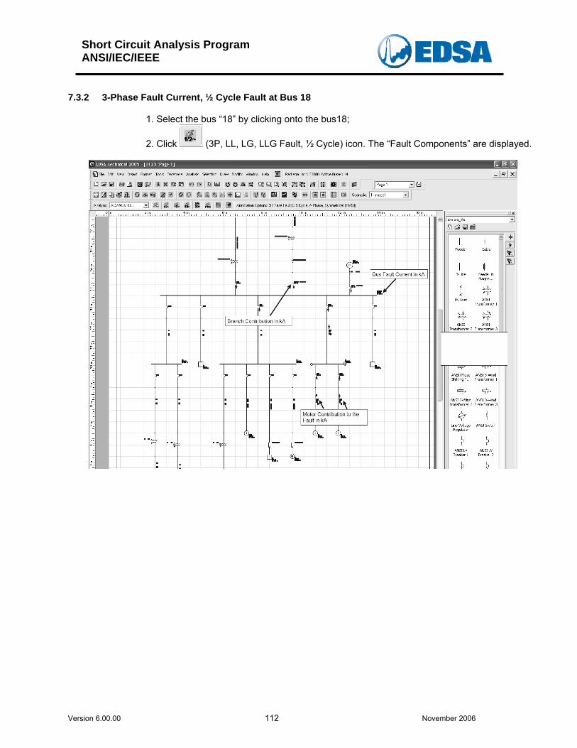
Short Circuit Analysis Program ANSI/IEC/IEEE
Version 6.00.00 112 November 2006
7.3.2 3-Phase Fault Current, ½ Cycle Fault at Bus 18
1. Select the bus “18” by clicking onto the bus18;
2. Click (3P, LL, LG, LLG Fault, ½ Cycle) icon. The “Fault Components” are displayed.
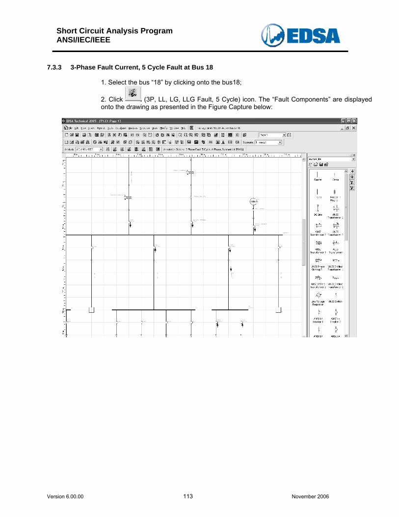
Short Circuit Analysis Program ANSI/IEC/IEEE
Version 6.00.00 113 November 2006
7.3.3 3-Phase Fault Current, 5 Cycle Fault at Bus 18
1. Select the bus “18” by clicking onto the bus18;
2. Click (3P, LL, LG, LLG Fault, 5 Cycle) icon. The “Fault Components” are displayed onto the drawing as presented in the Figure Capture below:
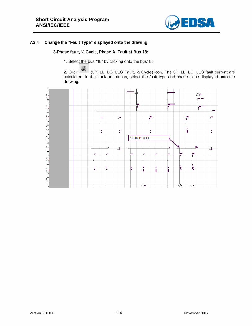
Short Circuit Analysis Program ANSI/IEC/IEEE
Version 6.00.00 114 November 2006
7.3.4 Change the “Fault Type” displayed onto the drawing.
3-Phase fault, ½ Cycle, Phase A, Fault at Bus 18:
1. Select the bus “18” by clicking onto the bus18;
2. Click (3P, LL, LG, LLG Fault, ½ Cycle) icon. The 3P, LL, LG, LLG fault current are calculated. In the back annotation, select the fault type and phase to be displayed onto the drawing.
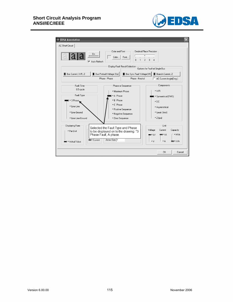
Short Circuit Analysis Program ANSI/IEC/IEEE
Version 6.00.00 115 November 2006
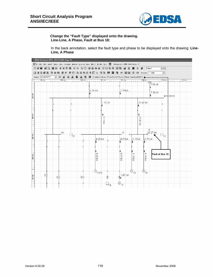
Short Circuit Analysis Program ANSI/IEC/IEEE
Version 6.00.00 116 November 2006
Change the “Fault Type” displayed onto the drawing. Line-Line, A Phase, Fault at Bus 18: In the back annotation, select the fault type and phase to be displayed onto the drawing: Line-Line, A Phase
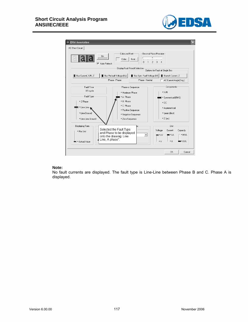
Short Circuit Analysis Program ANSI/IEC/IEEE
Version 6.00.00 117 November 2006
Note: No fault currents are displayed. The fault type is Line-Line between Phase B and C. Phase A is displayed.
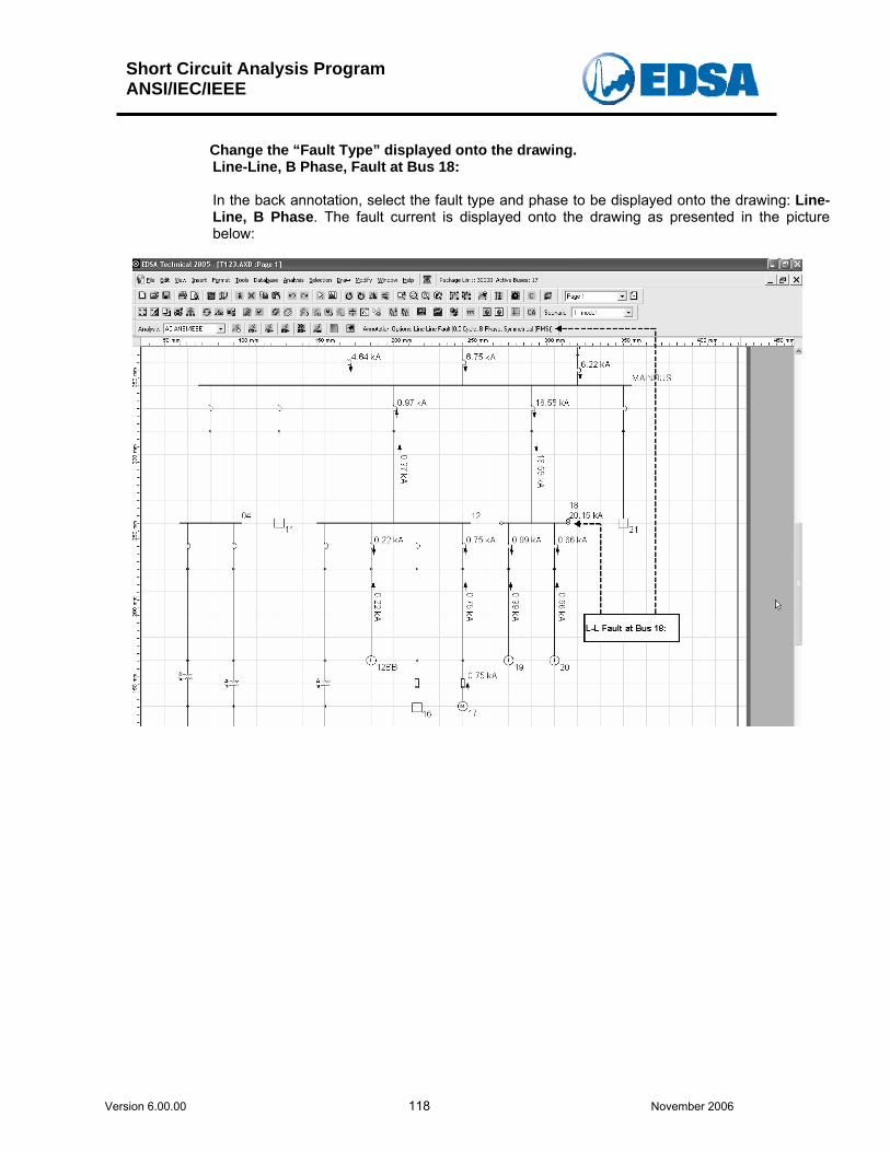
Short Circuit Analysis Program ANSI/IEC/IEEE
Version 6.00.00 118 November 2006
Change the “Fault Type” displayed onto the drawing. Line-Line, B Phase, Fault at Bus 18: In the back annotation, select the fault type and phase to be displayed onto the drawing: Line-Line, B Phase. The fault current is displayed onto the drawing as presented in the picture below:
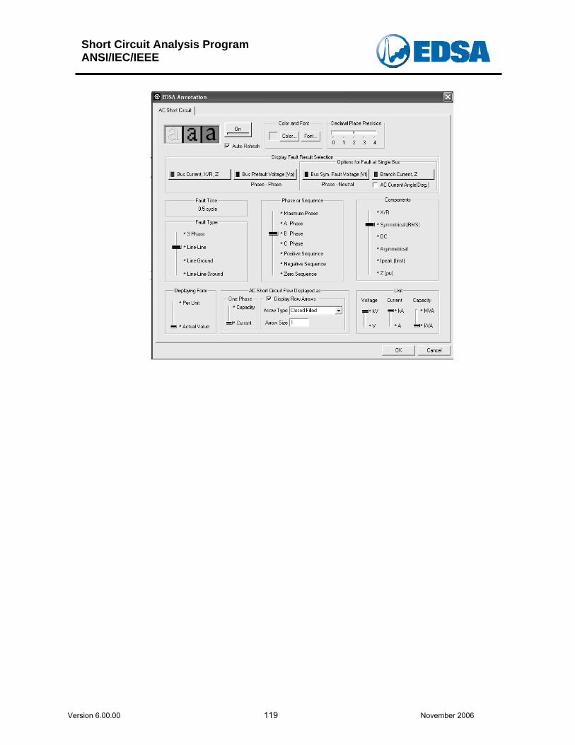
Short Circuit Analysis Program ANSI/IEC/IEEE
Version 6.00.00 119 November 2006
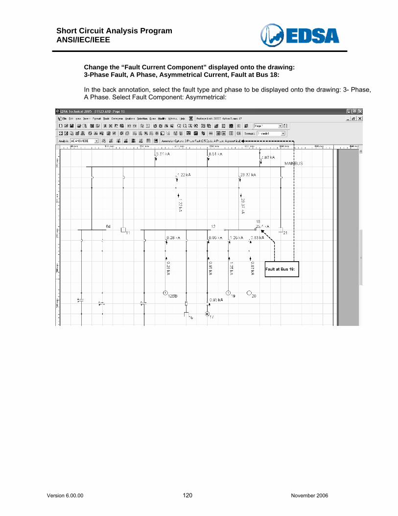
Short Circuit Analysis Program ANSI/IEC/IEEE
Version 6.00.00 120 November 2006
Change the “Fault Current Component” displayed onto the drawing: 3-Phase Fault, A Phase, Asymmetrical Current, Fault at Bus 18:
In the back annotation, select the fault type and phase to be displayed onto the drawing: 3- Phase, A Phase. Select Fault Component: Asymmetrical:
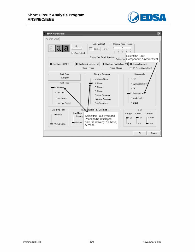
Short Circuit Analysis Program ANSI/IEC/IEEE
Version 6.00.00 121 November 2006