system impact study for the 17mw generation … · short circuit analysis short circuit analysis...
TRANSCRIPT

1
System Impact Study for the
17MW Generation Interconnection
10/14/2013

2
This document and any attachments hereto (“document”) is made available by Duke Energy Florida upon and subject to the express understanding that: (a) neither Duke Energy Florida nor any of its officers, directors, affiliates, agents, or employees makes any warranty, assurance, guarantee, or representation with respect to the contents of the document or the accuracy or completeness of the information contained or referenced in the document, and (b) Duke Energy Florida, its officers, directors, affiliates, agents, and employees shall not have any liability or responsibility for inaccuracies, errors , or omission in, or any business or policy decisions made by any direct or indirect recipient in reliance on, this document or the information contained or referenced therein; all such liability is expressly disclaimed.
3
Table of Contents
SUMMARY .................................................................................................................................................. 4
INTERCONNECTION POINT ................................................................................................................... 5
MODEL DEVELOPMENT .......................................................................................................................... 6
ANALYSIS PERFORMED .......................................................................................................................... 7
Steady State Contingency Analysis .................................................................................................................... 7
Short Circuit Analysis ......................................................................................................................................... 7
System Stability Analysis ................................................................................................................................... 8
INTERCONNECTION AND NETWORK UPGRADES ............................................................................ 8
APPENDIX A1: SUMMER PEAK STABILITY PLOTS ........................................................................... 9
APPENDIX A2: LIGHT LOAD STABILITY PLOTS ............................................................................. 19
APPENDIX B1: EXCITER OPEN CIRCUIT TEST PLOTS .................................................................. 29
APPENDIX B2: EXCITER RAPID RESPONSE TEST PLOTS ............................................................ 30
APPENDIX B3: GOVERNOR STEP LOAD TEST PLOTS ................................................................... 31

4
17MW Generator Interconnection Study Summary:
has submitted an interconnection request for 17MW. The System Impact Study will provide analysis of the four previously existing internal generating units at the site combined with the contribution of an additional generator to allow up to 17MW of site export and will evaluate the impact of this generation and subsequent export on grid reliability. Previously, the site has been considered a net load with no significant export capability until this request, thus no previous study exists to measure the affects of this new configuration with export. AC contingency (2012 winter 2013 summer), short circuit (2013 summer) and stability (2013 summer) analyses were performed. There were no constraints identified in the AC contingency analysis. There were no over-dutied devices identified on Duke Energy’s system in the short circuit analysis. Also, the addition of this generator and the 17MW export does not have an adverse effect on Duke Energy's transmission system. The results of this study will be shared with Seminole Electric Cooperative, Inc. (SECI) for their further evaluation of short circuit impact.
5
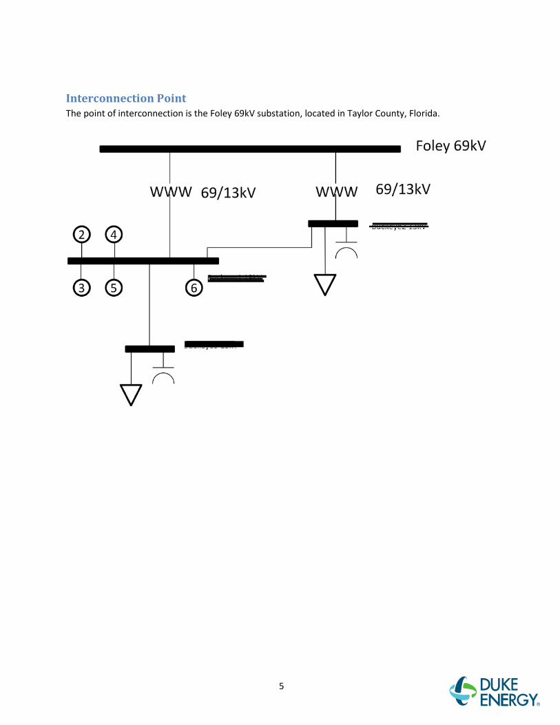
Interconnection Point The point of interconnection is the Foley 69kV substation, located in Taylor County, Florida.
6
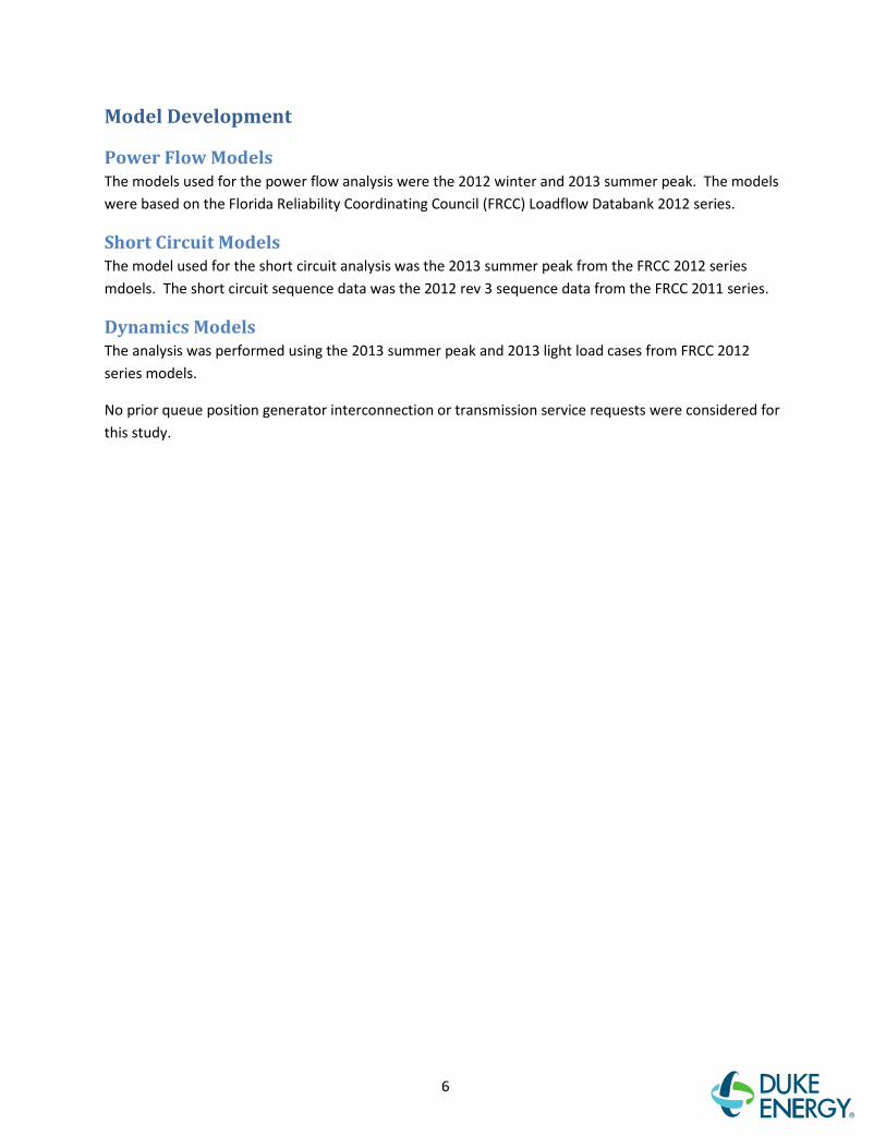
Model Development
Power Flow Models The models used for the power flow analysis were the 2012 winter and 2013 summer peak. The models were based on the Florida Reliability Coordinating Council (FRCC) Loadflow Databank 2012 series.
Short Circuit Models The model used for the short circuit analysis was the 2013 summer peak from the FRCC 2012 series mdoels. The short circuit sequence data was the 2012 rev 3 sequence data from the FRCC 2011 series.
Dynamics Models The analysis was performed using the 2013 summer peak and 2013 light load cases from FRCC 2012 series models.
No prior queue position generator interconnection or transmission service requests were considered for this study.
7
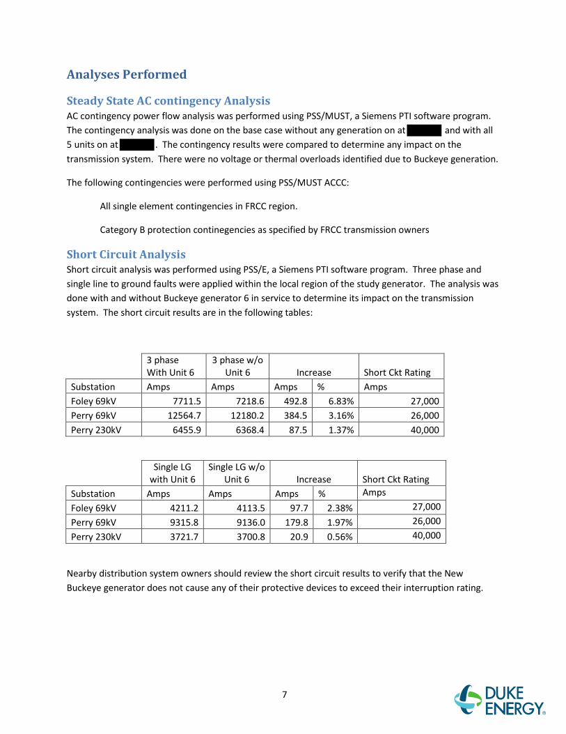
Analyses Performed
Steady State AC contingency Analysis AC contingency power flow analysis was performed using PSS/MUST, a Siemens PTI software program. The contingency analysis was done on the base case without any generation on at and with all 5 units on at . The contingency results were compared to determine any impact on the transmission system. There were no voltage or thermal overloads identified due to Buckeye generation.
The following contingencies were performed using PSS/MUST ACCC:
All single element contingencies in FRCC region.
Category B protection continegencies as specified by FRCC transmission owners
Short Circuit Analysis Short circuit analysis was performed using PSS/E, a Siemens PTI software program. Three phase and single line to ground faults were applied within the local region of the study generator. The analysis was done with and without Buckeye generator 6 in service to determine its impact on the transmission system. The short circuit results are in the following tables:
3 phase With Unit 6
3 phase w/o Unit 6 Increase Short Ckt Rating
Substation Amps Amps Amps % Amps Foley 69kV 7711.5 7218.6 492.8 6.83% 27,000 Perry 69kV 12564.7 12180.2 384.5 3.16% 26,000 Perry 230kV 6455.9 6368.4 87.5 1.37% 40,000
Single LG with Unit 6
Single LG w/o Unit 6 Increase Short Ckt Rating
Substation Amps Amps Amps % Amps
Foley 69kV 4211.2 4113.5 97.7 2.38% 27,000
Perry 69kV 9315.8 9136.0 179.8 1.97% 26,000
Perry 230kV 3721.7 3700.8 20.9 0.56% 40,000
Nearby distribution system owners should review the short circuit results to verify that the New Buckeye generator does not cause any of their protective devices to exceed their interruption rating.

8
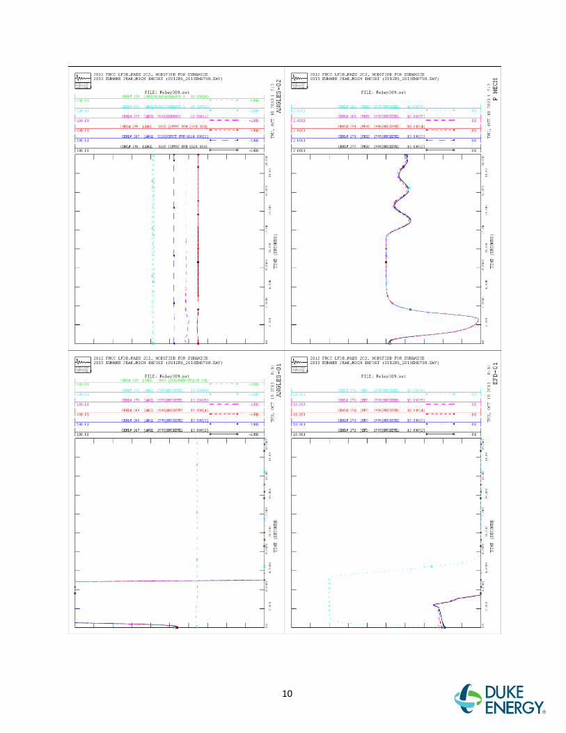
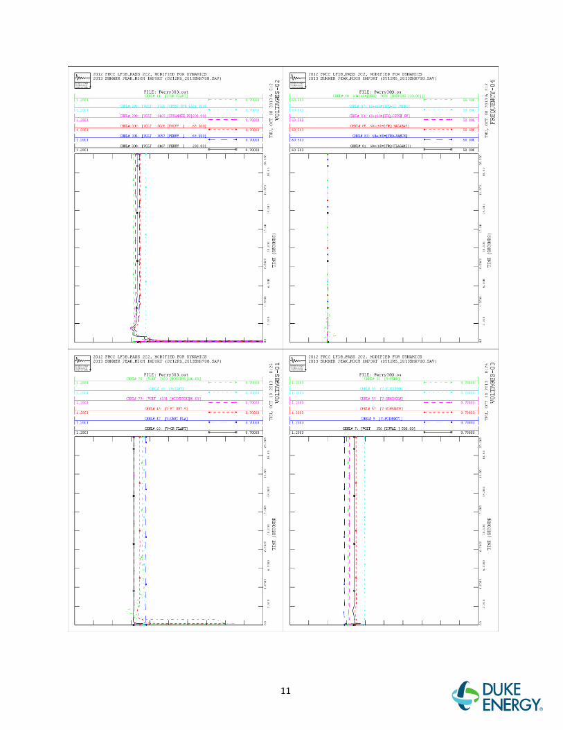
System Stability Analysis Based on the dynamic modeling data provided by the customer, the new generator at Buckeye does not have an adverse impact on Duke Energy's transmission system. The following are the list of faults tested for the dynamic stability analysis:
Contingency Name Description Sequence of Events Timing in Cycles
Foly309 3 phase fault at Foley 69kV
Clear remote ends 120.0
Prry303 3 phase fault at Perry 230kV on FLGASTRAN 230kV line
Clear Perry 230kV Clear FLGASTRAN 230kV Clear Killearn - Baker TP 115kV
4.0 26.0 90.0
Prry301 3 phase fault at Perry 230kV, stuck breaker at Perry 230kV
Clear Perry 69kV Clear Perry 230kV Clear FLGASTRAN 230kV Clear Killearn - Baker TP 115kV
6.0 15.0 16.0 76.0
Prry209 Single line to ground at Perry 230kV
Clear Perry - FLGASTRAN 230kV line Clear Perry - Suwannee River 230kV Clear Perry North 69kV Clear Boyd 69kV Clear Scanlon TP 69kV Clear ERIDU TP 69kV Clear Luraville 69kV Clear Obrien 69kV Clear Foley 69kV
30.0 50.0 90.0
Interconnection and Network Upgrades No interconnection or network upgrades on Duke Energy’s system were identified as needed in this study. The results of this study will be shared with SECI for their further evaluation of short circuit impact.

9
Appendix A1:- Summer Peak Stability Plots
10
11

12

13

14

15
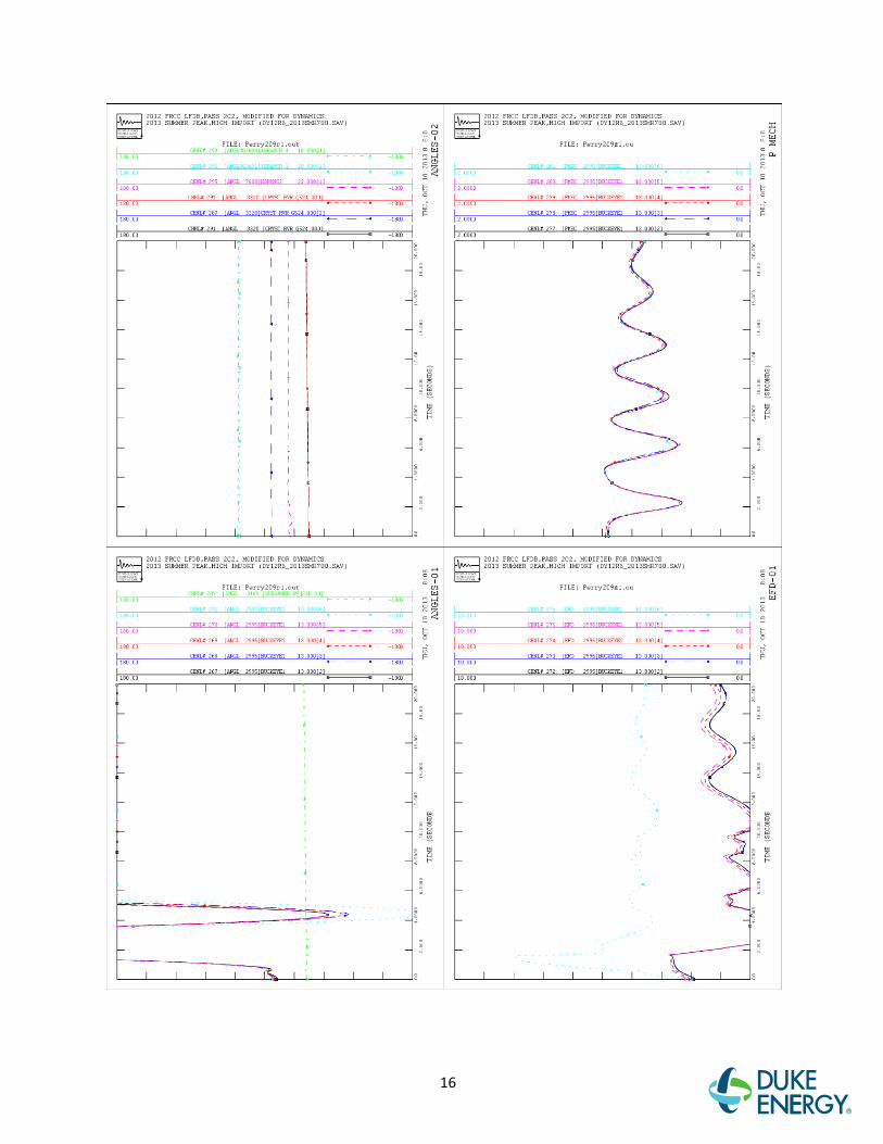
16

17

18

19
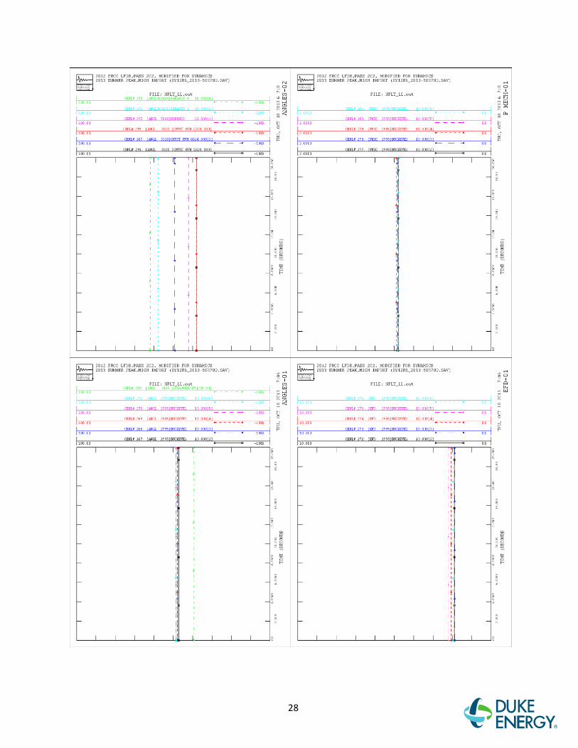
Appendix A2:- Light Load Stability Plots

20

21

22

23
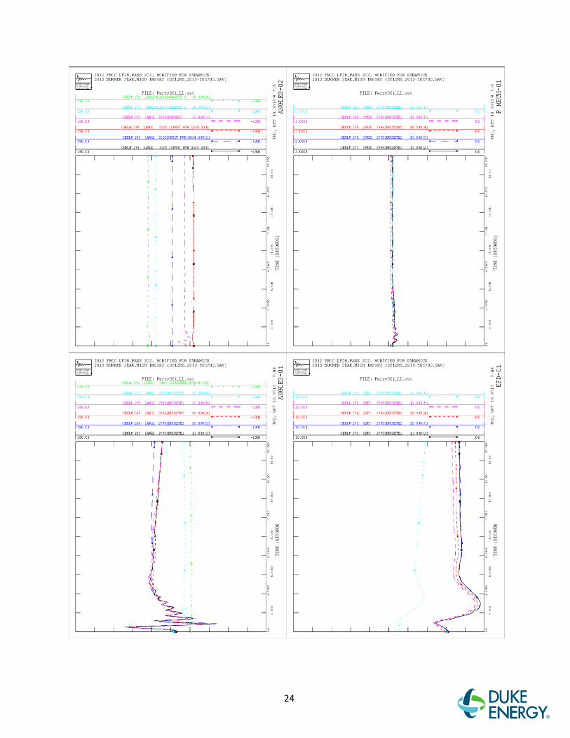
24

25

26

27
28

29
Appendix B1: Exciter Open Circuit Test Plots

30
Appendix B2: Exciter Rapid Response Test Plots

31
Appendix B3: Governor Step Load Test Plots
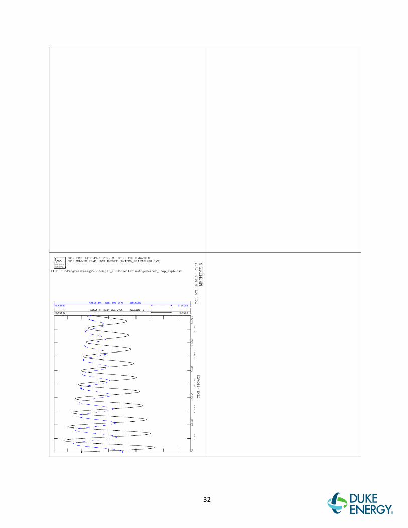
32