3. orthographic projections imain topics...3. orthographic projections iiithree rules aadjacentviews...
TRANSCRIPT

3. ORTHOGRAPHIC PROJECTIONS
I Main TopicsA Introduction to orthographic projectionsB Three rulesC Examples
9/4/19 GG303 1

3. ORTHOGRAPHIC PROJECTIONS
II Introduction to orthographic projectionsA Provide two-dimensional representations of objectsB Points are projected such that lines of projection are
all parallel and hence are all perpendicular to a single plane
C Points project as pointsD A line projects as a point only if viewed parallel to its
lengthE A plane projects as a line only if viewed edge-on
(parallel to the plane)
9/4/19 GG303 2

Orthographic projection: principal views of a rectangular parallelepiped
9/4/19 GG303 3

3. ORTHOGRAPHIC PROJECTIONS
F Principal views 1 Portray objects most simply: principal views
show the length, width, and height of rectangular parallelepipeds
2 Plane figures appear in true size and shape3 Lines appear in true length4 Principal view directions are perpendicular
to each other5 Three principal views needed to describe
objects
9/4/19 GG303 4

3. ORTHOGRAPHIC PROJECTIONSIII Three rules
A Adjacent views (e.g., top and front) are perpendicular, and projection lines are perpendicular to them. Two adjacent views share a common edge called a fold line.
B All projection lines in a given vieware parallel to one another. The projection lines connecting the projections of a point in adjacent views cross the common edge (fold line) at right angles.
C Related views (e.g., right and front) are adjacent to a common view (e.g., the top). The distance between a projected point and the edge (fold line) of the common view is the same in the related views. For example, point A is the the same distance below the top as seen in the related right and front views.
9/4/19 GG303 5

3. ORTHOGRAPHIC PROJECTIONS
IVExamplesA PointsB LinesC Planes
9/4/19 GG303 6

Orthographic Projections of a PointFig. 3.1.a
The front and right views are both adjacent to the top view. The front view isperpendicular to the top view, and the topview is perpendicular to the right view ;adjacent views are perpendicular to eachother. The projection or tie lines (thin lines) are viewing direction lines and are perpendicular to the fold lines (dashed lines). The front view (F) and right view (R) are related. Two adjacent views give enough information to construct a third view. For example, the top view and front view could be used to construct the right view: Point P is on projection lines perpendicular to the fold lines, and the front view tells us that point P isa distance zP from the top. Similarly, the front view could be created from the top viewand the right view. Both the front and right viewsgive the distance zP of point P from the top.
9/4/19 GG303 7
x =distance from the front view, y =distance from the left view, z =distance down from the top.Right-handed coordinate origin where the top, front, and left views intersect.

Orthographic Projections of a PointFig. 3.1.b
Here the right view is drawn adjacent to the front view. The top and right views are related. The top and right views are both adjacent to the front view. Both the top and right views give the distance xP of point P from the front.
9/4/19 GG303 8

Orthographic Projections of a PointFig. 3.1.c
The front view and view "A" are related. Both are adjacent to the top view, and both give the distance zP of point P from the top.
9/4/19 GG303 9

Orthographic Projections of a PointFig. 3.1.d
The top and view "B" are related. Both are adjacent to the front view, and both give the distance xP of point P from the front.
9/4/19 GG303 10

Orthographic Projections of a LineFig. 3.2.a
A line is defined by two points. Suppose we have with the information above. The two views provide information on the left-right, up-down, and front-back coordinates of the points, so that gives complete information on their positions.
9/4/19 GG303 11
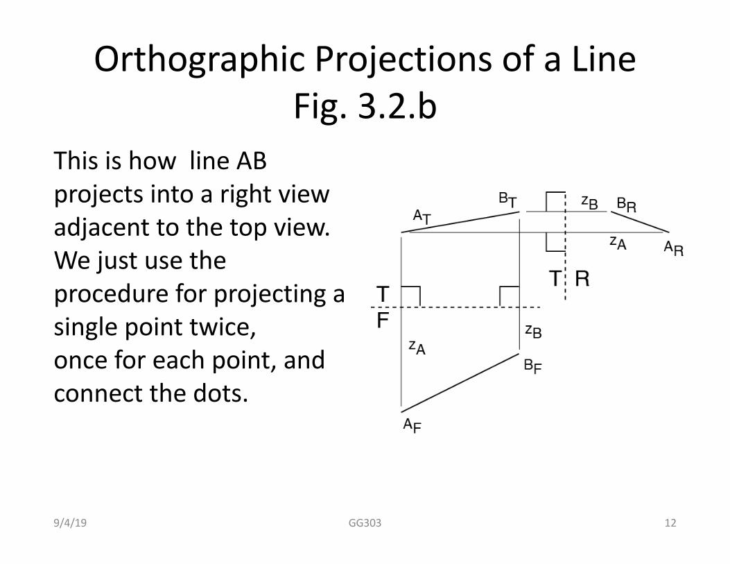
Orthographic Projections of a LineFig. 3.2.b
This is how line AB projects into a right viewadjacent to the top view. We just use the procedure for projecting a single point twice,once for each point, and connect the dots.
9/4/19 GG303 12

Orthographic Projections of a LineFig. 3.2.c
This is how line AB would project into a right view adjacent to the front view.
9/4/19 GG303 13

Orthographic Projections of a LineFig. 3.2.d
To find the length and plunge of AB we take a cross section parallel to the trend of the line (the trend is given in the top view). The length and plunge are in view C, adjacent to the top. A view "down the line" gives the end-on view of theline (view D) in which the line appears as a point.
9/4/19 GG303 14

Orthographic Projections of a PlaneFig. 3.3.a
Three points define a plane.The two adjacent views heregive complete information onthe positions of three pointsdefining plane ABC. This information might come froma cross section or a map.
Suppose we want to know thestrike and dip of plane ABC.We first need to find the strikeof the plane. The line of strikeis a horizontal line in plane ABC.
9/4/19 GG303 15

Orthographic Projections of a PlaneFig. 3.3.b
We find the line of strikeby intersecting a horizontalplane with plane ABC.We start with a vertical view(here that is the front view F) andthen project the line of strike into the top view T. The strike of the plane is measured in the top view by finding the direction of the (horizontal) line of strike. Thenumbers in parentheses in the top view are elevations, taken from the front view.
9/4/19 GG303 16
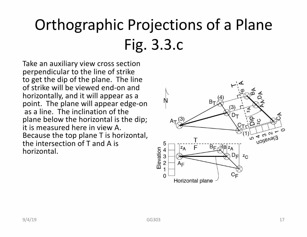
Orthographic Projections of a PlaneFig. 3.3.c
Take an auxiliary view cross sectionperpendicular to the line of strike to get the dip of the plane. The lineof strike will be viewed end-on andhorizontally, and it will appear as apoint. The plane will appear edge-onas a line. The inclination of the
plane below the horizontal is the dip; it is measured here in view A. Because the top plane T is horizontal, the intersection of T and A is horizontal.
9/4/19 GG303 17