21, rue d’artois, f-75008 paris 54 south africa 2015 http ... · insulators, right: 420 kv...
TRANSCRIPT
COMPACT OHTL INSULATION– FUTURE TRENDS AND TECHNOLOGIES
LEHRETZ, Fabian SEIFERT, Jens Martin
Lapp Insulators GmbH – BU LIKE
Germany
TROPPAUER, Wolfgang
Mosdorfer – BU MOVE
Austria
SUMMARY
The planning process for new overhead transmission lines (OHTL) in north Europe is more than challenging.
Due to the general shutdown of nuclear power plants in Germany, a reorientation of energy distribution is
necessary. Electrical energy from Off-shore wind parks in the North Sea or solar power plants at the rural
areas have to be transferred over big distances to the heavy industry in the south of the country. Due to the
new situation new transmission lines, such as HVAC and HVDC at 400/420 kV and 500/550 kV, are
necessary. On the other hand, the acceptance of new OHTL constructions by population is presently extreme
low, driven by the environmental and visual impact of large OHTL structures. Possible countermeasures are
the usage of existing line corridors and the application of higher transmission voltages by using up to date
insulating structures, such as:
Insulating cross-arms
Inverted V sets
Semi-anchored sets
Y and T assemblies
Interphase and intersystem spacer
This paper reports on the state of the art of technology, mechanical and electrical design considerations, type
tests and static/dynamic mechanical load performance limits of OHTL insulation. In the most cases
composite insulators are applied, due to their better pollution performance, dynamic impact loads and shorter
insulating length. In addition to the above mentioned solutions, a complete new indea of compacting lines by
means of bundling the 3 phases of a system in a “Diamond” arrangement for 420 kV is presented. The report
closes with case studies of already realized and future planned constructions in Germany, South Africa,
Turkey, Belgium, United States and United Kingdom. An outlook is given to the ideas for standardization,
e.g. as an application guide within the new family of IEC 62609-X for composite line post insulators and
their assemblies.
KEYWORDS Composite Insulators, Compact OHTL, Cross-arm, HVDC
21, rue d’Artois, F-75008 PARIS 54 SOUTH AFRICA 2015
http : //www.cigre.org
2
1.0 Compact Insulation Elements
This chapter gives a survey about insulation elements based on modern composite insulators [1]
applied for compact overhead transmission line design up to system voltages of Um=550 kV.
Composite insulators can be manufactured in single units, possess high mechanical impact strengths,
fail-safe characteristics and are resistant to severe pollution conditions [2].
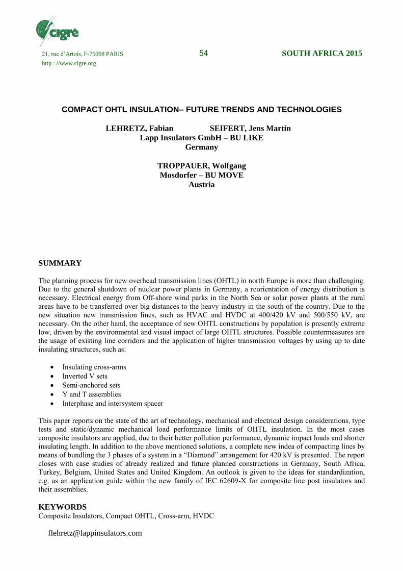
1.1 Horizontal V Sets
The fixed (non-pivoting) base assembly (Fig. 1) is applied in structures that have to accommodate
longitudinal loads e.g. angle towers. Some national standards request this type of assembly in case of
road crossings. The longitudinal load performance depends strongly on the FRP core diameter and on
the geometry of the assembly. For high longitudinal loads (such as in the case of conductor breakage)
the post insulators are arranged horizontally in V shape (Fig. 1 middle). The fixed base assembly
requires special construction elements at the tower side (base of the assembly). In case of parallel post
arrangements the tower and connection components and fixing devices (screws) have to withstand
significant bending moments. Torsional loads to the tower have to be considered in case of V shaped
post insulators.
Fig. 1: 420 kV Fixed Base Horizontal V Assemblies (left: parallel posts, middle: V setup of post
insulators, right: 420 kV Horizontal (Pivoting) V Assembly)
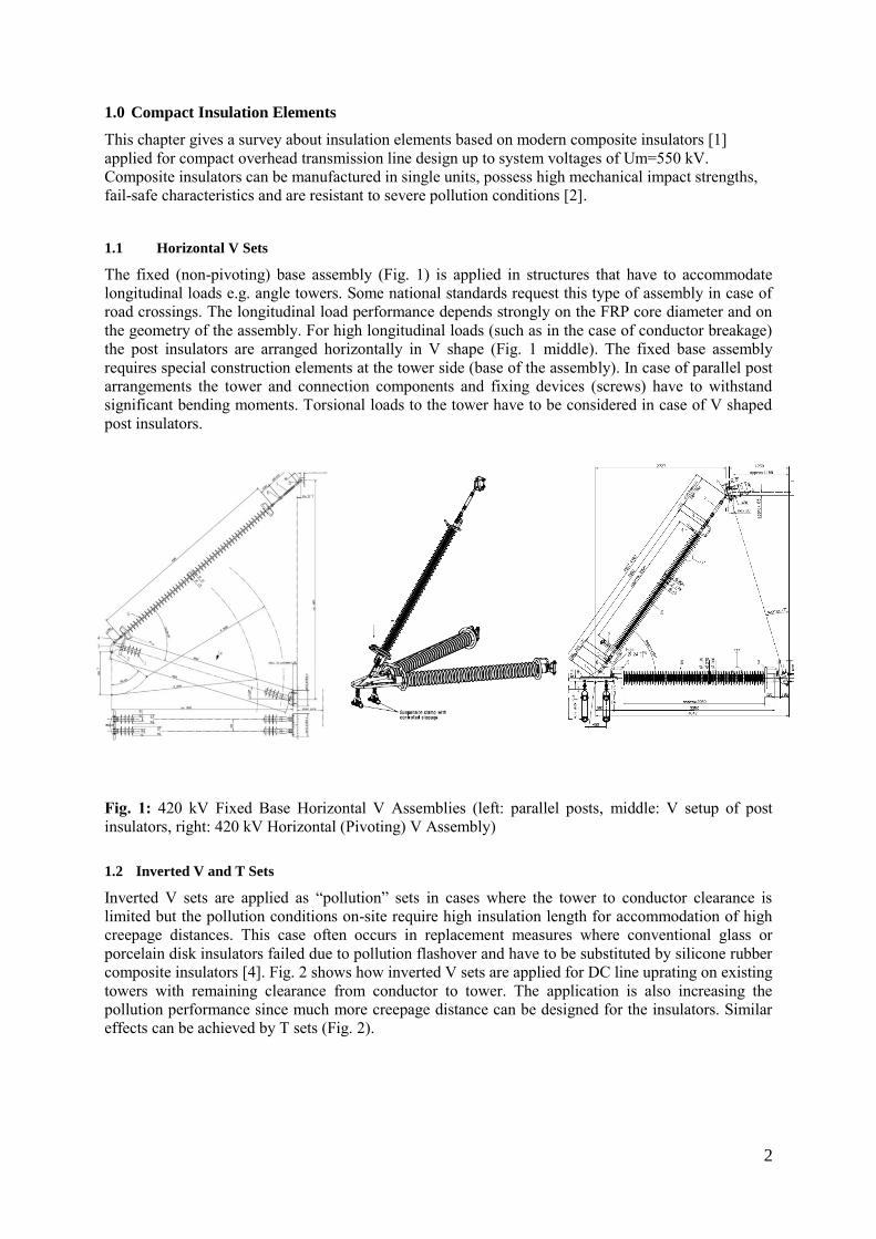
1.2 Inverted V and T Sets
Inverted V sets are applied as “pollution” sets in cases where the tower to conductor clearance is
limited but the pollution conditions on-site require high insulation length for accommodation of high
creepage distances. This case often occurs in replacement measures where conventional glass or
porcelain disk insulators failed due to pollution flashover and have to be substituted by silicone rubber
composite insulators [4]. Fig. 2 shows how inverted V sets are applied for DC line uprating on existing
towers with remaining clearance from conductor to tower. The application is also increasing the
pollution performance since much more creepage distance can be designed for the insulators. Similar
effects can be achieved by T sets (Fig. 2).
3
DC 533kV DC 560 kV DC 600 kV
Fig. 2: Inverted V and T (pollution) sets for the accommodation of very high creepage distance on
“limited” tower clearance for 533, 560 and 600 kV DC applications [4].
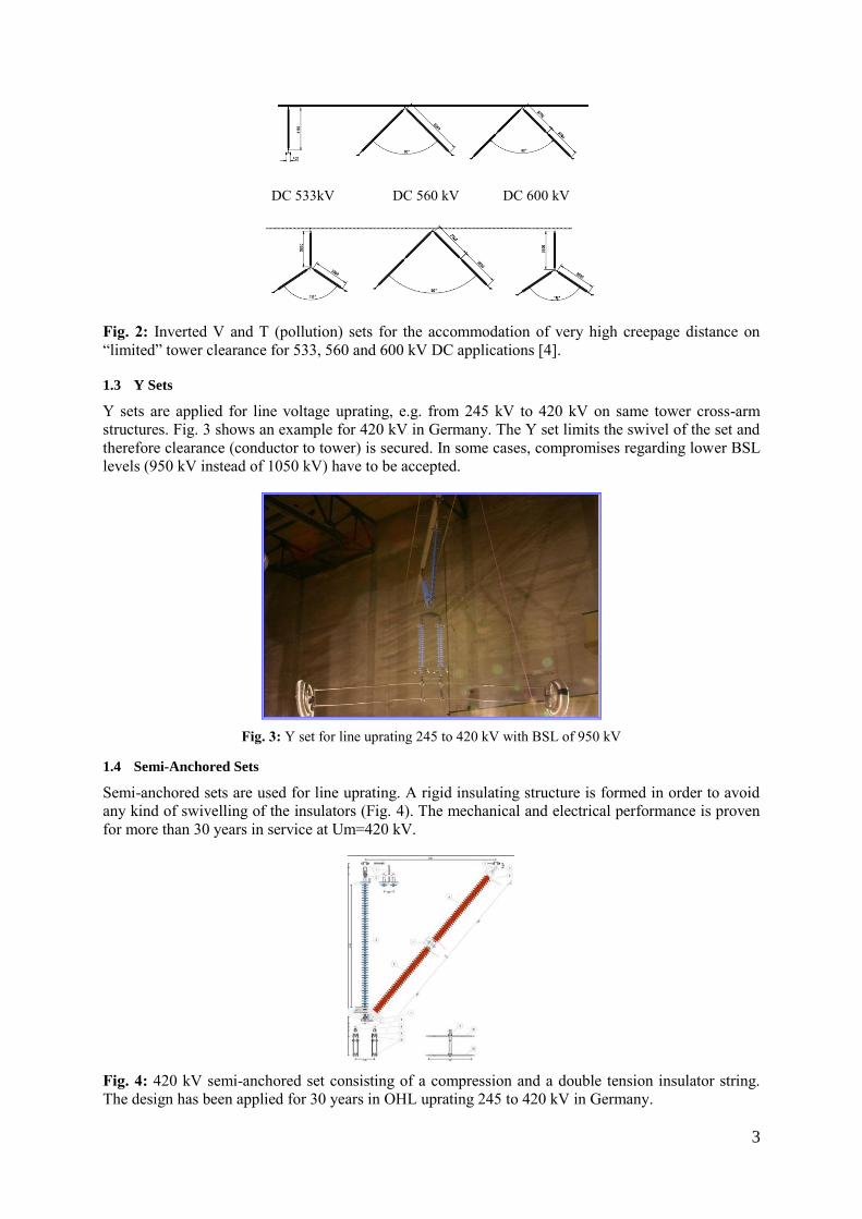
1.3 Y Sets
Y sets are applied for line voltage uprating, e.g. from 245 kV to 420 kV on same tower cross-arm
structures. Fig. 3 shows an example for 420 kV in Germany. The Y set limits the swivel of the set and
therefore clearance (conductor to tower) is secured. In some cases, compromises regarding lower BSL
levels (950 kV instead of 1050 kV) have to be accepted.
Fig. 3: Y set for line uprating 245 to 420 kV with BSL of 950 kV
1.4 Semi-Anchored Sets
Semi-anchored sets are used for line uprating. A rigid insulating structure is formed in order to avoid
any kind of swivelling of the insulators (Fig. 4). The mechanical and electrical performance is proven
for more than 30 years in service at Um=420 kV.
Fig. 4: 420 kV semi-anchored set consisting of a compression and a double tension insulator string.
The design has been applied for 30 years in OHL uprating 245 to 420 kV in Germany.
4
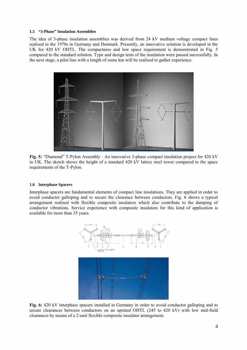
1.5 “3-Phase” Insulation Assemblies
The idea of 3-phase insulation assemblies was derived from 24 kV medium voltage compact lines
realised in the 1970s in Germany and Denmark. Presently, an innovative solution is developed in the
UK for 420 kV OHTL. The compactness and low space requirement is demonstrated in Fig. 5
compared to the standard solution. Type and design tests of the insulation were passed successfully. In
the next stage, a pilot line with a length of some km will be realised to gather experience.
Fig. 5: “Diamond” T-Pylon Assembly - An innovative 3-phase compact insulation project for 420 kV
in UK. The sketch shows the height of a standard 420 kV lattice steel tower compared to the space
requirements of the T-Pylon.
1.6 Interphase Spacers
Interphase spacers are fundamental elements of compact line insulations. They are applied in order to
avoid conductor galloping and to secure the clearance between conductors. Fig. 6 shows a typical
arrangement realised with flexible composite insulators which also contribute to the damping of
conductor vibrations. Service experience with composite insulators for this kind of application is
available for more than 35 years.
Fig. 6: 420 kV interphase spacers installed in Germany in order to avoid conductor galloping and to
secure clearances between conductors on an uprated OHTL (245 to 420 kV) with low mid-field
clearances by means of a 2-unit flexible composite insulator arrangement.
5
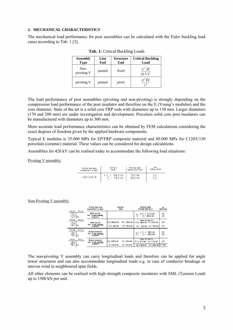
2. MECHANICAL CHARACTERISTICS
The mechanical load performance for post assemblies can be calculated with the Euler buckling load
cases according to Tab. 1 [3].
Tab. 1: Critical Buckling Loads
Assembly
Type
Line
End
Structure
End
Critical Buckling
Load
Non-
pivoting V pinned fixed
2
2
)7.0(
EI
pivoting V pinned pivot 2
2
EI
The load performance of post assemblies (pivoting and non-pivoting) is strongly depending on the
compression load performance of the post insulator and therefore on the E (Young’s modulus) and the
core diameter. State of the art is a solid core FRP rods with diameters up to 130 mm. Larger diameters
(170 and 200 mm) are under investigation and development. Porcelain solid core post insulators can
be manufactured with diameters up to 300 mm.
More accurate load performance characteristics can be obtained by FEM calculations considering the
exact degrees of freedom given by the applied hardware components.
Typical E modulus is 35.000 MPa for EP/FRP composite material and 80.000 MPa for C120/C130
porcelain (ceramic) material. These values can be considered for design calculations.
Assemblies for 420 kV can be realised today to accommodate the following load situations:
Pivoting V assembly:
Non-Pivoting V assembly:
The non-pivoting V assembly can carry longitudinal loads and therefore can be applied for angle
tower structures and can also accommodate longitudinal loads e.g. in case of conductor breakage or
uneven wind in neighboured span fields.
All other elements can be realised with high strength composite insulators with SML (Tension Load)
up to 1500 kN per unit.
6
3. ELECTRICAL CHARACTERISTICS
Compact OHTL line insulation shall be designed in accordance with IEC 60071-1 [5]. In some cases
lower BIL or BSL levels have to be accepted e.g. in case of Y insulator sets. For V (vertical and
horizontal) assemblies the recommended insulation levels can be met in most cases. For phase-phase
insulation IEC 60071-1 and IEC 60815 [6] shall be applied which leads typically to increased values
of BIL/BSL (factor 1.5) and creepage distance (factor 3).
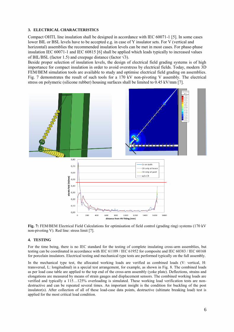
Beside proper selection of insulation levels, the design of electrical field grading systems is of high
importance for compact insulation in order to avoid overstress by electrical fields. Today, modern 3D
FEM/BEM simulation tools are available to study and optimise electrical field grading on assemblies.
Fig. 7 demonstrates the result of such tools for a 170 kV non-pivoting V assembly. The electrical
stress on polymeric (silicone rubber) housing surfaces shall be limited to 0.45 kV/mm [7].
Fig. 7: FEM/BEM Electrical Field Calculations for optimisation of field control (grading ring) systems (170 kV
non-pivoting V). Red line: stress limit [7].
4. TESTING
For the time being, there is no IEC standard for the testing of complete insulating cross-arm assemblies, but
testing can be coordinated in accordance with IEC 61109 / IEC 61952 for composite and IEC 60383 / IEC 60168
for porcelain insulators. Electrical testing and mechanical type tests are performed typically on the full assembly.
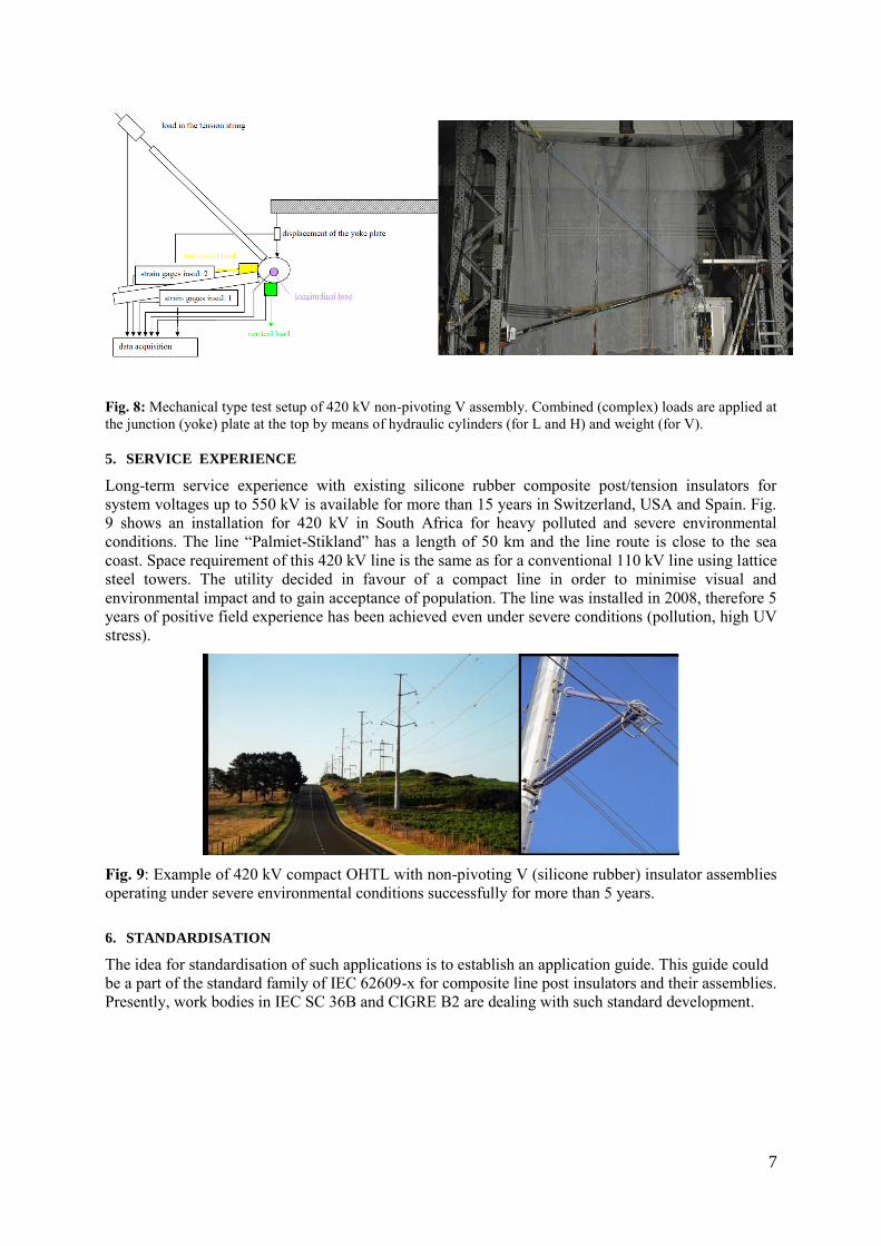
In the mechanical type test, the allocated working loads are verified as combined loads (V: vertical, H:
transversal, L: longitudinal) in a special test arrangement, for example, as shown in Fig. 8. The combined loads
as per load case table are applied to the top end of the cross-arm assembly (yoke plate). Deflections, strains and
elongations are measured by means of strain gauges and displacement sensors. The combined working loads are
verified and typically a 115…125% overloading is simulated. These working load verification tests are non-
destructive and can be repeated several times. An important insight is the condition for buckling of the post
insulator(s). After collection of all of these load-case data points, destructive (ultimate breaking load) test is
applied for the most critical load condition.
7
Fig. 8: Mechanical type test setup of 420 kV non-pivoting V assembly. Combined (complex) loads are applied at
the junction (yoke) plate at the top by means of hydraulic cylinders (for L and H) and weight (for V).
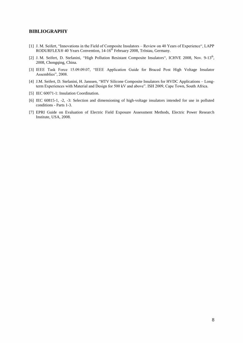
5. SERVICE EXPERIENCE
Long-term service experience with existing silicone rubber composite post/tension insulators for
system voltages up to 550 kV is available for more than 15 years in Switzerland, USA and Spain. Fig.
9 shows an installation for 420 kV in South Africa for heavy polluted and severe environmental
conditions. The line “Palmiet-Stikland” has a length of 50 km and the line route is close to the sea
coast. Space requirement of this 420 kV line is the same as for a conventional 110 kV line using lattice
steel towers. The utility decided in favour of a compact line in order to minimise visual and
environmental impact and to gain acceptance of population. The line was installed in 2008, therefore 5
years of positive field experience has been achieved even under severe conditions (pollution, high UV
stress).
Fig. 9: Example of 420 kV compact OHTL with non-pivoting V (silicone rubber) insulator assemblies
operating under severe environmental conditions successfully for more than 5 years.
6. STANDARDISATION
The idea for standardisation of such applications is to establish an application guide. This guide could
be a part of the standard family of IEC 62609-x for composite line post insulators and their assemblies.
Presently, work bodies in IEC SC 36B and CIGRE B2 are dealing with such standard development.
8
BIBLIOGRAPHY
[1] J. M. Seifert, “Innovations in the Field of Composite Insulators – Review on 40 Years of Experience“, LAPP
RODURFLEX® 40 Years Convention, 14-16th
February 2008, Tröstau, Germany.
[2] J. M. Seifert, D. Stefanini, “High Pollution Resistant Composite Insulators“, ICHVE 2008, Nov. 9-13th,
2008, Chongqing, China.
[3] IEEE Task Force 15.09.09.07, “IEEE Application Guide for Braced Post High Voltage Insulator
Assemblies”, 2008.
[4] J.M. Seifert, D. Stefanini, H. Janssen, “HTV Silicone Composite Insulators for HVDC Applications – Long-
term Experiences with Material and Design for 500 kV and above”. ISH 2009, Cape Town, South Africa.
[5] IEC 60071-1: Insulation Coordination.
[6] IEC 60815-1, -2, -3: Selection and dimensioning of high-voltage insulators intended for use in polluted
conditions - Parts 1-3.
[7] EPRI Guide on Evaluation of Electric Field Exposure Assessment Methods, Electric Power Research
Institute, USA, 2008.