inverted microscope instruction manual - fisher...
TRANSCRIPT

Inverted MicroscopeInstruction Manual
Model 11350119

2
Introduction
Thank you for your purchase of a Fisher Scientific microscope. Your new microscope is a precision instrument carefully checked to assure that it reaches you in good condition. It is designed for ease of operation and years of carefree use. The information in this manual probably far exceeds what you will need to know in order to operate, troubleshoot and maintain your microscope. However, it is provided to answer questions that might arise, and to help you avoid any maintenance expense that may be unnecessary.

3
Fisher Scientific Inverted Microscope
Table of Contents
Nomenclature 4-5
Specifications 6
Setting Up the Microscope 7
Assembling the Microscope Input Voltage 7
Installing the Lamp 7
Mounting the Condenser 8
Installing the Objectives 8
Mechanical Stage 8
Mounting the Eyepieces 8
Microscopic Procedure: Interpupillary Distance Adjustment 9
Diopter Adjustment 9
Centering the Condenser 9
Centering the Lamp 10
Brightfield Microscopy 10
Phase Contrast Microscopy 11
Photomicrographic Procedure 12
Troubleshooting Table 13
Care and Maintenance 14
Lenses and Filters 14
Cleaning of Painted or Plastic Components 14
When Not in Use 14
Fisher Scientific Warranty 15
4
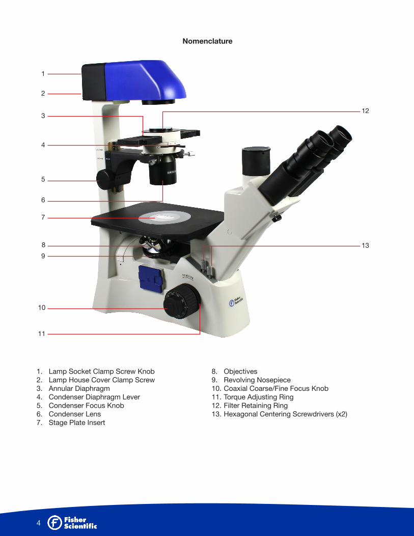
Nomenclature
1. Lamp Socket Clamp Screw Knob 2. Lamp House Cover Clamp Screw 3. Annular Diaphragm4. Condenser Diaphragm Lever5. Condenser Focus Knob6. Condenser Lens7. Stage Plate Insert
8. Objectives9. Revolving Nosepiece10. Coaxial Coarse/Fine Focus Knob11. Torque Adjusting Ring12. Filter Retaining Ring13. Hexagonal Centering Screwdrivers (x2)
1
2
3
4
5
6
7
9
8
10
11
12
13

5
1. Vertical Photo Port 2. Interpupillary Distance Scale3. Diopter Adjustment Ring 4. Eyepiece 5. Optical Path Selector Lever6. Filter Slider 7. Lamp House 8. Field Diaphragm Lever 9. Condenser Clamp Screw
10. Phase Slider11. Condenser Clamp Holder Screw12. Condenser Centering Screws13. Stage Plate14. Fluorescence Filter cassette Mount15. Power Switch16. Light Intensity Control Dial17. Brightness Indicator (LED Segmented Display)
1
2
3
4
5
6
7
8
910
11
12
13
14
15
16
17

6
Specifications
• Magnification Ratio: 40X - 200X• Eyepiece: Objective Field Ø22• Objectives:
• Condenser: N.A. 0.3 / W.D. 72mm• Electrical Specifications:
» Input: 90-240V~, 35W, 50-60Hz » Lamp: DC6V, 30W Halogen » Fuse: 250V T2.5A
(If the original fuse is damaged, please replace with a new one.)
Magnification N.A. W.D. (mm)
Plan Achromat 4X 0.10 23.5
Plan Achromat Phase 10X 0.25 7.5
Plan Achromat Phase LWD 20X 0.40 7.0

7
Setting Up the Microscope
Working environment• The location should be free from dust, moisture, chemical vapors and mechanical vibrations. • Do not place the instrument in a warm and/or humid environment.• Locate the instrument where the operator’s line of vision is not directed towards a window, a lamp or a well-
lit bright wall. The quality of the viewed image from the microscope will deteriorate where there is significant ambient light.
Assembling the microscope Input voltage
• Automatic voltage selection works with electrical outlets worldwide. However, always use a power cord that is rated for the voltage used in your area and that has been approved to meet local safety standards. Using the wrong power cord could cause fire or equipment damage.
• In case of using the extension cord, use only the power supply cord with the PE (protective earth) wire.• In order to prevent electric shock, always turn the power switch on the power supply off before connecting
the power cord.
1. Installing the lamp• In order to prevent electric shock always turn the power switch off and unplug the power cord before
replacing the lamp.• Release lamp housing cover clamp screw using a coin to remove the cover.
• Firmly insert the lamp into the socket pinholes until it reaches the limit, be careful not to tilt the • lamp when mounting.• When installing the lamp, do not touch the glass surface of the lamp with bare fingers. Doing so • will cause fingerprints, grease, etc., to burn onto the lamp surface, reducing the illumination provided
by the lamp. If surface is contaminated, wipe it clean using lens tissue.• Close the cover and fasten with it with lamp housing cover clamp screw.
Power Cord
Power Switch
Lamp Housing Cover Clamp Screw

8
• Insert the filter slider with mat surface of the diffuser turned towards the user.2. Mounting the Condenser
• Mount the ELWD condenser on the circular dovetail mount of the condenser holder with the aperture diaphragm lever facing toward the eyepieces.
• Insert the Ph annular diaphragm slider with centering hexagonal socket head screws facing
• the front.• The centerable condenser mount is height adjustable with rack and pinion and is dovetail • mounted on the illuminating pillar with a clamp screw.
3. Installing the Objectives• Remove the stage plate insert from the stage.• Install the objectives into the nosepiece so that the magnification increases with clockwise rotation of
the revolving nosepiece.• Replace the stage plate insert.
4. Mechanical Stage• Secure the mechanical stage to the 11350119 plain stage using the two mounting screws located
beneath the stage on the right side
5. Mounting the Eyepieces• Remove the dust caps from the eyepiece tubes.• Insert the eyepieces into the eyepiece tubes.• If the rubber eye guards are to be used, fit them in the groove around the eyepiece.
Condenser Clamp Screw

9
Microscopic Procedure: Interpupillary Distance Adjustment
• Before adjusting the interpupillary distance, bring a specimen into focus using the 10x objective.• Adjust the interpupillary distance so that both the right and left field of view become one.• This adjustment will enable the user to observe the specimen with both eyes.
1. Diopter Adjustment• Diopter adjustment compensates for differences in vision between the left and right eyes. In addition to
making observation through both eyes easier, this adjustment also reduces the extent to which focusing is lost when the objective magnification is changed. In particular, this occurs when a low power objective is used.
• Before adjusting the diopter, bring a specimen into focus using the 10x objective.• Turn the diopter compensation ring on each eyepiece until the adjustment ring is adjusted to “0”
position.
• Position the highest magnification objective into the optical path and bring the specimen image into focus by turning the coarse and fine focus knobs.
• Position either 4x or 10x objective into optical path. Without adjusting the fine and coarse focus knobs, turn the diopter rings on the eyepieces so that the specimen images in the left and right eyepieces are focused individually.
• Repeat the above step twice.2. Centering the Condenser
• Set the Phase annular diaphragm slider in center position (O).• Fully open the field of view diaphragm.• Move the aperture diaphragm lever in open “O” position.• Bring the specimen image into focus, using the 10x objective.• Close the field of view diaphragm to its minimum setting. • Turn the condenser focus knob so that the image of the field diaphragm forms on the specimen
surface.
• Adjust the condenser centering screws so that the center of the field diaphragm image matches the center of the field of view. This adjustment is easier to make if the field diaphragm size is reduced to
Diopter adjustment“0” position

10
slightly smaller than the eyepiece field of view.• For normal observation, the size of the diaphragm should be just outside the edge of the field of view.
3. Centering the Lamp • Set the Phase annular diaphragm slider in the center position (O).• Fully open the field of view diaphragm.• Move the aperture diaphragm lever to the open “O” position.• Using the 10x Phase contrast objective, bring the specimen image into focus.• Remove the diffuser filter slider from the light path.• Remove an eyepiece and insert the phase centering telescope in its place.• Holding the knurled part of the centering telescope, rotate its eyepiece to focus on the phase plate
image of the objective. • Release the lamp socket clamp screw using the knob.
• Move the lamp socket with the knurled knob to bring the lamp filament image to the center of the phase plate image of the objective.
• After finishing the above lamp centering procedure, insert the filter slider with mat surface of the diffuser turned towards the user.
4. Brightfield Microscopy• Set the Phase annular diaphragm slider in the center position (O).• Bring the specimen image into focus.• Adjust the opening of the field of view diaphragm, for normal observation the size of the diaphragm
should be just outside the edge of the field of view.• The condenser aperture diaphragm is provided for adjusting the numerical aperture (N.A.) of the
illuminating system of the microscope. It is important because it determines the resolution of the image, contrast, depth of focus and brightness.
• Reducing the aperture diaphragm will lower the resolution and brightness but increase the contrast and depth of focus.
Lamp Socket Clamp Screw Knob

11
5. Phase Contrast Microscopy• Phase contrast objectives are labeled Ph.• Fully open the aperture diaphragm.• Bring the 10x (Ph1) objective into optical path.
• Position the Phase annular diaphragm slider to 10 -20. Set slider to 40 when using a 40x (Ph3) objective (optional).
• Remove either eyepiece from the eyepiece tube and insert the phase centering telescope in its place.• Rotate the eyepiece of the centering telescope to focus on both the phase plate image of the objective
and the annular diaphragm image of the phase slider. • If the objective phase plate and the annular of the slider do not coincide, use the two hexagonal
screwdrivers supplied with the microscope to bring the slider annular ring to the center of the phase plate, so that the image of the annular diaphragm is concentric with the phase plate image.
• If the slider annular ring image is moved from the phase plate image in the objective, a low phase contrast image will result.
• For phase contrast microscopy at the maximum contrast, use GIF (Green Interference Filter) in the optical path.
• Place the filter in the designated retaining ring above the phase annular diaphragm slider.

12
Photomicrographic Procedure
• The optical path selector lever can be used to set the optical path to either the binocular tube 100:0/0:100 (beam split for fluorescence) or binocular tube/vertical tube 20:80/100:0 (for brightfield or phase).
• Before starting photomicrography, check the following:• The condenser is centered.• The condenser annular diaphragm is centered.• The field of view diaphragm is reduced to slightly just outside the edge of the field of view.
• For photomicrographic procedures, refer to the manual of the specific camera being used.
Filter Selection
Filter Type Procedure
GIF (Green Interference) 546nm For phase contrast and contrast adjustment with black and white film.
NCB (Neutral Color Balance) Blue For general microscopy and color photos.
Never attempt either of the following actions. Doing so will damage the focusing mechanism.• Rotate the left and right knob while holding the other.• Turning the coarse and fine focus knobs further than their limit.

13
Troubleshooting Table
The troubleshooting table below contains the most frequently encountered problems and their possible causes.
Optical and Operating Problems
Electrical
Problem Possible Cause
Vignetting or uneven brightness in the field of view or field of view only partially visible
• Lamp not installed properly• Filter slider in intermediate position• Phase slide not in click-stop position• Incorrect condenser mounting• Condenser is set too low• Condenser is not centered• Field diaphragm is closed too far• Aperture diaphragm is closed too far• Revolving nosepiece not clicked into position• Optical path selector in intermediate position
Dust or dirt in field of view• Aperture diaphragm is closed too far• Field of view diaphragm not focused on specimen surface• Dust or dirt on specimen’s surface
Image quality: No image under phase contrast or details cannot be viewed
• Brightfield objective being used• Phase annular diaphragm not in optical path• Phase annular diaphragm and objective phase symbol do not match• Slider annual ring image has moved away from the objective phase
plate image• Field of view diaphragm image not focused on specimen surface• Thickness of specimen holder is outside the compensating range of
objective
Eye strain or fatigue
• Interpupillary distance not adjusted• Diopter adjustment not made• Inadequate illumination• Field of view of left and right eyepiece differ
Problem Possible Cause
Lamp does not light• Power supply not plugged in• Lamp not installed• Lamp burnt out
Inadequate brightness • Specified lamp not being used
Lamp blows out immediately • Specified lamp not being used
Lamp flickers• Connectors are not securely connected• Lamp near end of service life• Lamp not securely plugged into socket

14
Care and Maintenance
1. Lenses and Filters• To clean lens surfaces or filters, first remove dust using compressed air. If dust still persists, use a soft/
clean brush or gauze.• If excessive dirt or grease gets on lens surfaces, a small amount of distilled water or eyeglass lens
cleaner can be used on a lens tissue.• Do not use same area of gauze or tissue, to wipe more than once.
2. Cleaning of Painted or Plastic Components• Do not use organic solvents (thinners, alcohol, ether, etc.). Doing so could result in discoloration or in
the peeling of paint.• For stubborn dirt, moisten a piece of gauze with diluted detergent and wipe clean.
3. When Not in Use• When not in use, cover the instrument with dust cover and store in a place low in humidity where mold
is not likely to form. • Store the objectives, eyepieces and filters in a container or desiccator with drying agent.
15
Fisher Scientific Warranty
The Fisher Scientific 5 Year Warranty assures that the microscope is guaranteed against defects in material and workmanship for 5 years from the purchase date of the product. Electrical components are covered for three years; video components are covered for one year after purchase. Normal wear, routine maintenance, light bulbs, power supplies, rechargers, batteries, fuses, cords, add-on accessories, damage resulting from repair by unauthorized parties, accident, alteration, shipping, misuse or abuse is not covered. Warranty service is provided by National Optical & Scientific Instruments, Inc.’s authorized technicians. Determination of warranty is at the technician’s discretion.
The Fisher Scientific Warranty for cameras is 1 year.
Other than set forth above, Fisher Scientific hereby disclaims all warranties, expressed or implied, of fitness for a particular purpose.
Defective products covered by the warranty will be repaired free of charge when they are returned, postpaid, to:
Fisher Scientificc/o National Optical & Scientific Instruments, Inc.Attn: Warranty Repair6508 Tri-County ParkwaySchertz, TX 78154
For all warranty repairs or service requests, please call Fisher Scientific repair department at (800) 766-7000 before anything is shipped. This warranty gives you specific legal rights, and you may also have other rights which vary from state to state.
*For customers living outside the United States, Fisher Scientific will provide standard warranty service. However, inbound and outbound shipping cost is the responsibility of the consumer.

© 2014 Thermo Fisher Scientific Inc. All rights reserved.