2016 catalog oxford instruments x-ray technology · 2 oxford instruments x-ray technology 2016...
TRANSCRIPT
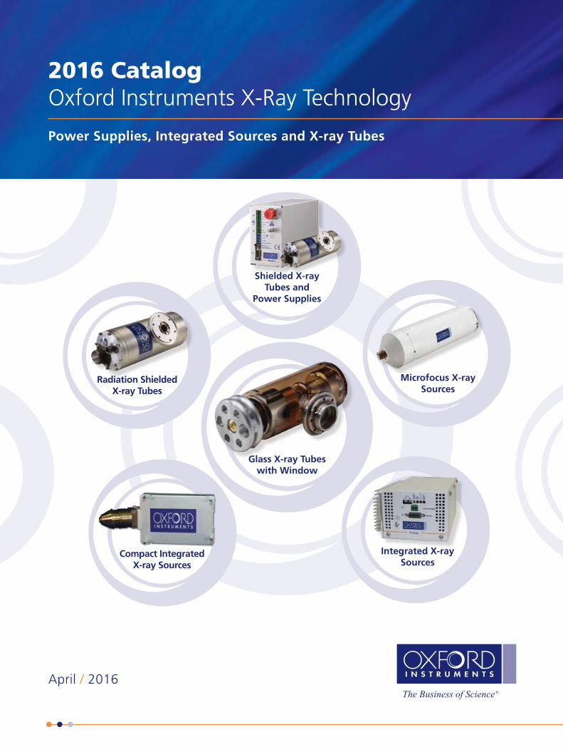
2016 CatalogOxford Instruments X-Ray Technology
Power Supplies, Integrated Sources and X-ray Tubes
April / 2016
Glass X-ray Tubeswith Window
Radiation ShieldedX-ray Tubes
Compact IntegratedX-ray Sources
Integrated X-raySources
Microfocus X-raySources
Shielded X-ray Tubes and
Power Supplies
2 Oxford Instruments X-Ray Technology
2016 Catalog
April 2016
X-RAY TECHNOLOGY
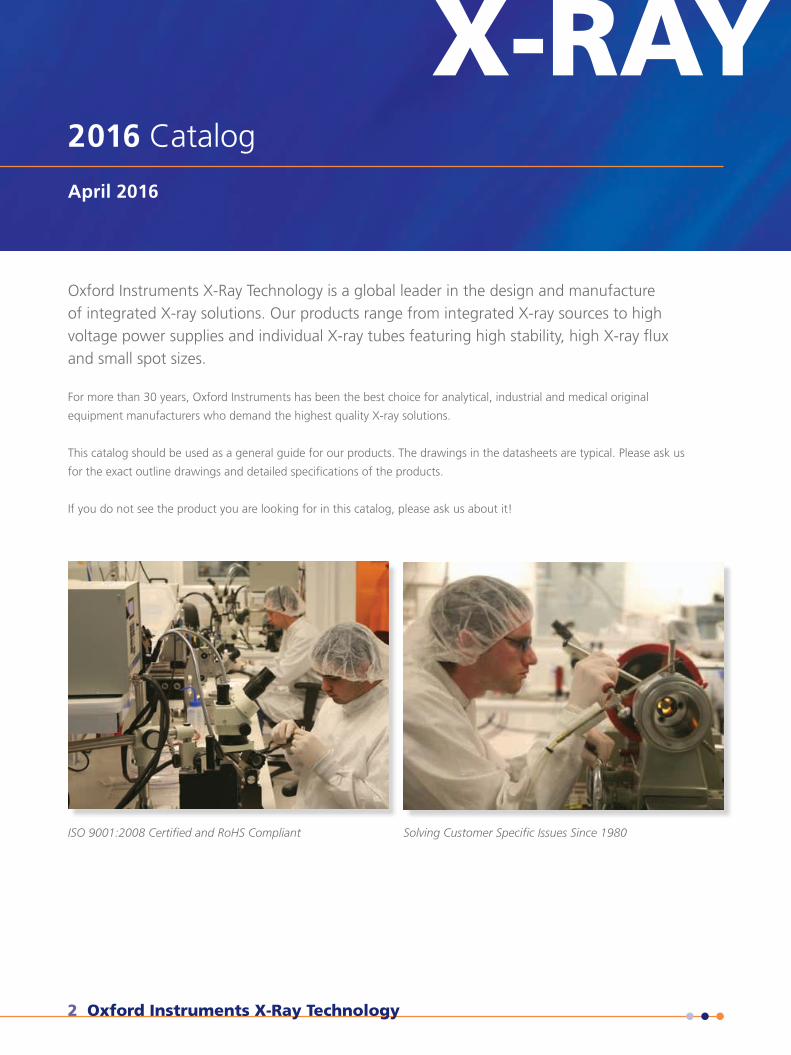
Oxford Instruments X-Ray Technology is a global leader in the design and manufacture of integrated X-ray solutions. Our products range from integrated X-ray sources to high voltage power supplies and individual X-ray tubes featuring high stability, high X-ray flux and small spot sizes.
For more than 30 years, Oxford Instruments has been the best choice for analytical, industrial and medical original
equipment manufacturers who demand the highest quality X-ray solutions.
This catalog should be used as a general guide for our products. The drawings in the datasheets are typical. Please ask us
for the exact outline drawings and detailed specifications of the products.
If you do not see the product you are looking for in this catalog, please ask us about it!
ISO 9001:2008 Certified and RoHS Compliant Solving Customer Specific Issues Since 1980
Phone: +1 (831) 439-9729 Email: [email protected] 3
2016 Catalog
X-RAY TECHNOLOGYTable of Contents
Integrated X-ray SourcesScafell Pike Integrated X-ray Source 4
Trinity 80kV, 33μm, 40 Watt Integrated X-ray Source 6
UltraBright 96000 Series 90kV Microfocus X-ray Source 8
Nova 96000 Series 90kV Water-Cooled Microfocus X-ray Source 12
Radiation Shielded X-ray TubesPinnacles 50kV Microfocus X-ray Source 16
Neptune 5200 Series Water-Cooled Radiation Shielded X-ray Tube 18
Jupiter 5000 Series Radiation Shielded X-ray Tube 20
Apogee 5500 Series Radiation Shielded X-ray Tube 22
Potted X-ray Tubes3000 Series 30kV X-ray Tube 24
Glass X-ray Tubes1000 Series Glass X-ray Tube 26
1500 Series Glass X-ray Tube 28
1501 Series Glass X-ray Tube 30
1550 Series Glass X-ray Tube 32
Power SuppliesShasta Series X-ray Tube Power Supply 34
AppendixComplete Listing of X-ray Tubes, Integrated Sources and Cables 36
Conditioning Procedure Application Note 42
X-ray Spectra Application Note 43
Operating Range Application Note 46
X-ray Tube Packaging Application Note 48
Beryllium Window Application Note 49
Filament Life Application Note 50
Shielding Application Note 52
Heat Management Application Note 55
X-ray Fluorescence Periodic Table 57
4 Oxford Instruments X-Ray Technology
X-RAYX-RAYIntegrated X-ray SourceScafell Pike
Specifications
Operating Voltage Range:
Maximum power:
Beam current:
Focal spot size (maximum):
Focus to Object Distance (FOD):
Target material:
Window material and thickness:
Input voltage:
Input voltage ripple:
Control signals:
Time to warm up to 50kV and 0.1mA:
Continuous flux stability:
Cooling method:
Max case operating temp:
Ambient operating temp:
Radiation leakage:
Weight:
Storage conditions:
Technical Datasheet
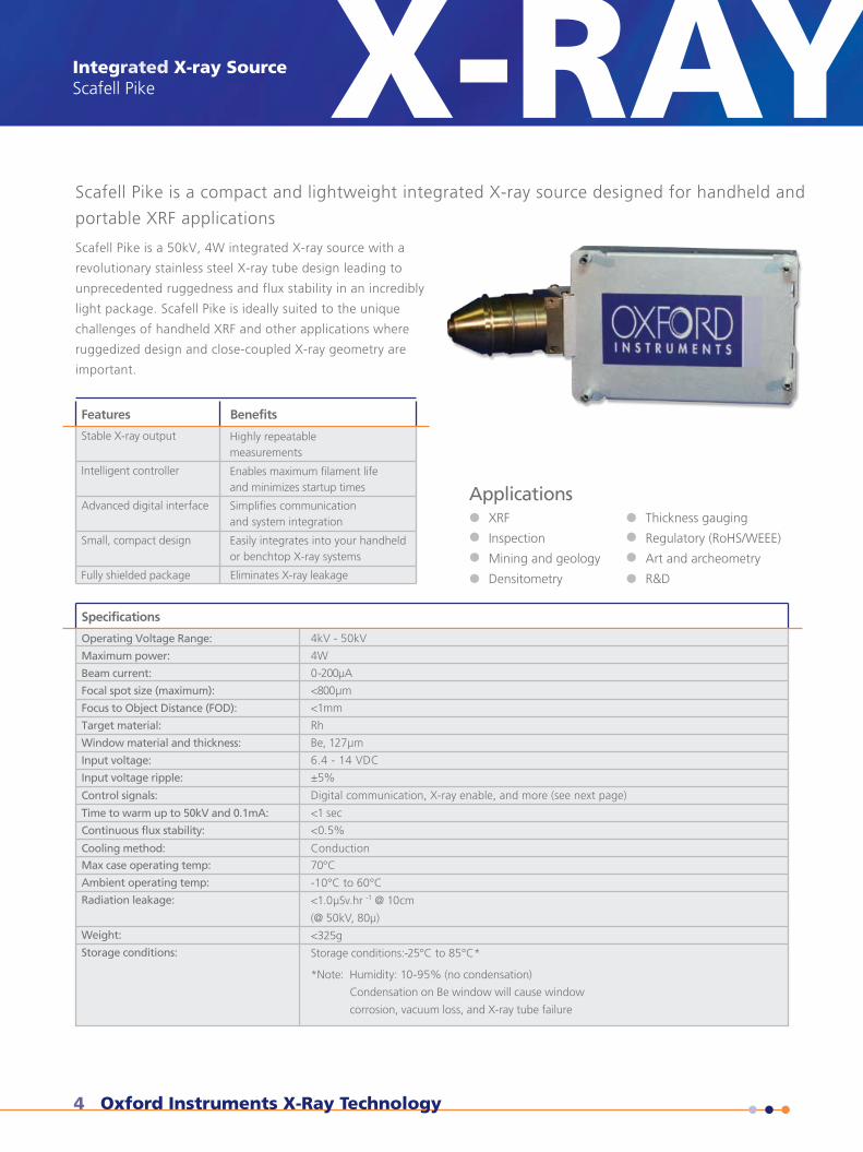
Scafell Pike is a compact and lightweight integrated X-ray source designed for handheld and
portable XRF applications
XRF
Inspection
Mining and geology
Densitometry
Thickness gauging
Regulatory (RoHS/WEEE)
Art and archeometry
R&D
Applications
4kV - 50kV
4W
0-200µA
<800µm
<1mm
Rh
Be, 127µm
6.4 - 14 VDC
±5%
Digital communication, X-ray enable, and more (see next page)
<1 sec
<0.5%
Conduction
70°C
-10°C to 60°C
<1.0µSv.hr -1 @ 10cm
(@ 50kV, 80µ)
<325g
Storage conditions:-25°C to 85°C*
*Note: Humidity: 10-95% (no condensation)
Condensation on Be window will cause window
corrosion, vacuum loss, and X-ray tube failure
Features Benefits
Stable X-ray output
Intelligent controller
Advanced digital interface
Small, compact design
Fully shielded package Eliminates X-ray leakage
Highly repeatable measurements
Enables maximum filament life and minimizes startup times
Simplifies communication and system integration
Easily integrates into your handheld or benchtop X-ray systems
Scafell Pike is a 50kV, 4W integrated X-ray source with a
revolutionary stainless steel X-ray tube design leading to
unprecedented ruggedness and flux stability in an incredibly
light package. Scafell Pike is ideally suited to the unique
challenges of handheld XRF and other applications where
ruggedized design and close-coupled X-ray geometry are
important.
Integrated X-ray SourceScafell Pike
Phone: +1 (831) 439-9729 Email: [email protected] 5
X-RAY Technical DatasheetDS9100025
X-ray Technology360 El Pueblo RoadScotts Valley, CA 95066, USA
Phone: +1 (831) 439-9729Fax: +1 (831) 439-6050Email: [email protected]
THE QUEEN'S AWARDS
FOR ENTERPRISE:
INNOVATION
2012
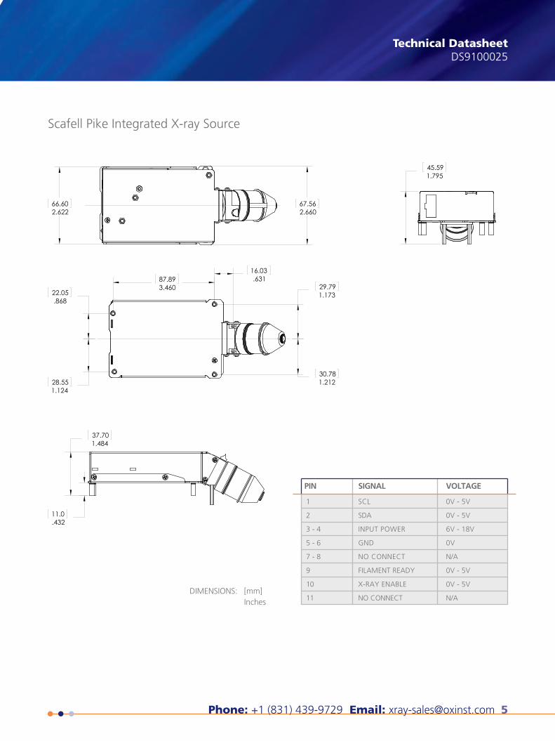
Scafell Pike Integrated X-ray Source
1
2
3 - 4
5 - 6
7 - 8
9
10
11
SCL
SDA
INPUT POWER
GND
NO CONNECT
FILAMENT READY
X-RAY ENABLE
NO CONNECT
0V - 5V
0V - 5V
6V - 18V
0V
N/A
0V - 5V
0V - 5V
N/A
PIN SIGNAL VOLTAGE
DIMENSIONS: [mm]Inches
This publication is the copyright of Oxford Instruments plc and provides outline information only, which (unless agreed by the company in writing) may not be used, applied or reproduced for any purpose or form part of any order or contract or regarded as the representa-tion relating to the products or services concerned. Oxford Instruments’ policy is one of continued improvement. The company reserves the right to alter, without notice the specification, design or conditions of supply of any product or service. Oxford Instruments acknowl-edges all trademarks and registrations. © Oxford Instruments plc, 2016. All rights reserved. Document reference: Part no: DS9100025 - April 4, 2016
visit www.oxford-instruments.com/xt or [email protected] for more information
45.591.795
67.562.660
66.602.622
29.791.173
30.781.212
22.05.868
28.551.124
87.893.460
16.03.631
37.701.484
11.0.432
6 Oxford Instruments X-Ray Technology
X-RAY80kV, 33um, 40 Watt Integrated X-ray SourceTrinity X-RAY80kV, 33um, 40W Integrated X-ray SourceTrinity
Specifications
Operating Voltage Range:
Maximum Power:
Maximum Beam Current:
Target Material:
Focal Spot Size:
Cone of Illumination:
Spot to Window Spacing (FOD):
Window Material & Thickness:
Accuracy:
Flux Stability:
Rise Time:
Duty Cycle:
Ripple:
Temperature Coefficient:
Temperature Conditions:
Humidity:
Method of Cooling:
Thermal Cut-Off:
Shielding:
Size:
Weight:
Input Power:
Interface:
Safety & Regulatory Compliance:
Technical Datasheet
Medical imaging Inspection of printed circuit boards and electronic devices Nondestructive testing of plastic, metal and mechanical parts CT imaging for life sciences and industrial inspection applications
Small, stable spot delivers distortion free measurements Compact, programmable, integrated package enables ease of installation and improved reliability XT proprietary shielding minimizes weight while ensuring extremely low radiation leakage LED indicators provide constant system status Fully lead-free and RoHS compliant
Food or Packaging imaging
Applications
20-80kV
40W
10-500µA
W
33µm (Nominal CEI/IEC 60336:2005)
37°
27mm ± 1mm
1.40 mm (0.055") Glass & 3.60mm (0.142") Polystyrene
kV: < 0.50%
µA: < 1.0%
≤ 0.2% over 4-hour period
≤ 200 ms (from standby)
Continuous
1% RMS @ 80kV, 500µA
1000ppm/°C
Operating: Maximum 55°C at tube heat sink
Storage: -10°C to 50°C
15°C to 40°C ; 0-95% RH up to 5,000ft
External cooling required and directed at the unit at 100 CFM
55°C ± 3°C at tube heat sink
Less than 0.1 mR/hour at 5cm away from surface of the unit when operated at 80kV, 500µA as
per FDA 21 CFR 1020.40
10.5" L x 5.8" W x 4.0" H (266mm L x 146mm W x 101mm H)
≤ 9 lbs.
22-26 VDC, 3A
Analog (0-10VDC), RS422 & RS485
Designed to meet UL, CE and RoHS Directive 2011/65/EU
Benefits
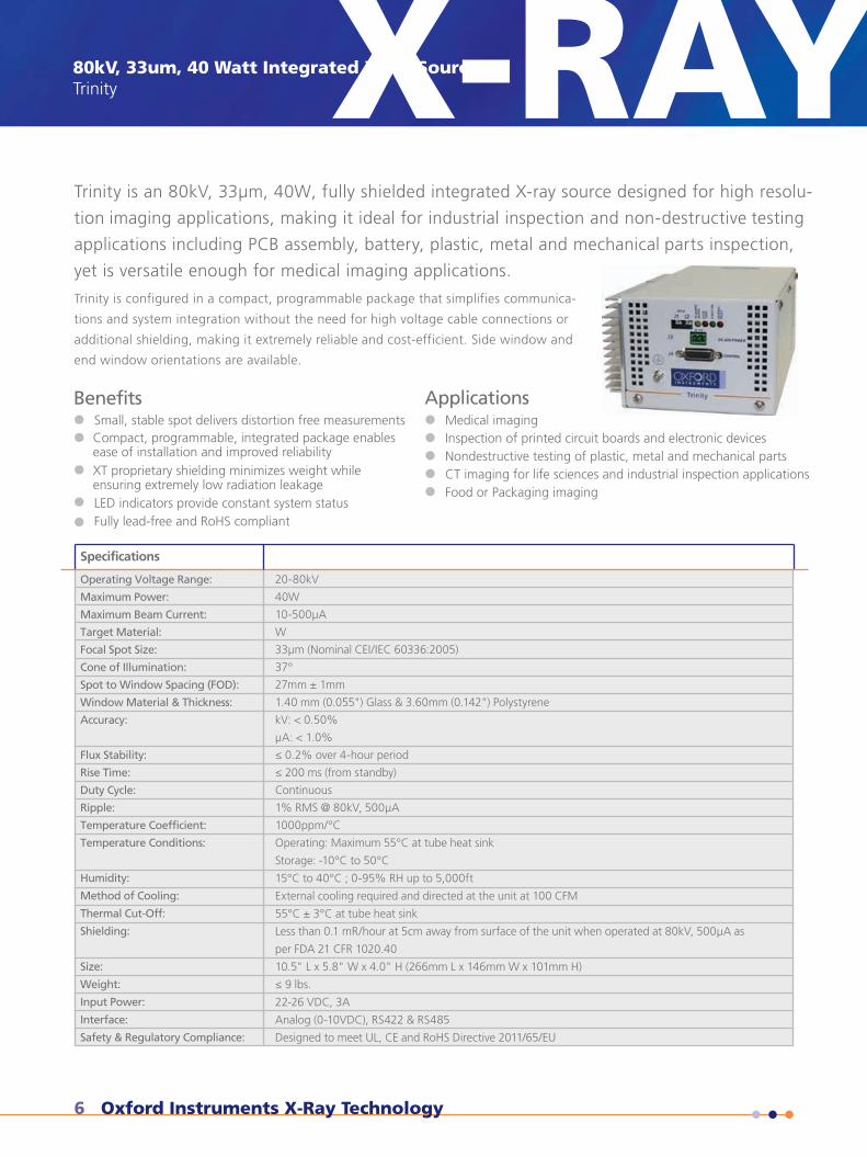
Trinity is an 80kV, 33µm, 40W, fully shielded integrated X-ray source designed for high resolu-
tion imaging applications, making it ideal for industrial inspection and non-destructive testing
applications including PCB assembly, battery, plastic, metal and mechanical parts inspection,
yet is versatile enough for medical imaging applications.
Trinity is configured in a compact, programmable package that simplifies communica-
tions and system integration without the need for high voltage cable connections or
additional shielding, making it extremely reliable and cost-efficient. Side window and
end window orientations are available.
Phone: +1 (831) 439-9729 Email: [email protected] 7
X-RAY
www.oxford-instruments.com/xt
This publication is the copyright of Oxford Instruments plc and provides outline information only, which (unless agreedby the company in writing) may not be used, applied or reproduced for any purpose or form part of any order orcontract or regarded as the representation relating to the products or services concerned. Oxford Instruments’ policy
conditions of supply of any product or service. Oxford Instruments acknowledges all trademarks and registrations.© Oxford Instruments X-Ray Technology, 2015. All rights reserved. Document part number: DS9100004 - July 1, 2015
Oxford Instruments X-Ray Technology360 El Pueblo Road, Suite 104Scotts Valley, CA 95066, USA
Phone: +1 (831) 439-9729Fax: +1 (831) 439-6050Email: [email protected]
DIMENSIONS: Inches [mm]
10.47 266
3.99 101.2
10.89 276.7
.41 10.524VDC FAN CONNECTOR
100 CFM FAN REQIURED, LOCATED WITHIN 4.00 MAX OF THIS SURFACE
1.0 26.4X-RAY EXIT
0 0.47 11.9
.47 11.9
1.77 44.9
1.77 44.9
2.63 66.8
3.22 81.8
00
.81
20.6
.81
20.6
1.44
36.6
1.16
29.5
2.00
50.7
1.99
50.5
*M5X0.8-6H(4X)
+M6X1.0-6H(4X)
COOLING FINS
.47 11.9
.47 11.9
1.77 44.9
1.77 44.9
2.63 66.7
3.22 81.8
.8822
.41.2
632
.8120
.6
1.72
43.8
8.46
215
9.22
234.2
9.63
244.6
.81
20.6
*M5X08-6H(4X)
+M6X1.0-6H(6X)
COOLING FINS
5.85 148.5
M4X0.7-5HGND STUD
COOLING VENTS
COOLING VENTS
CONTROLDC POWER
.47 11.9
.47 11.9
1.77 44.9
1.77 44.9
2.63 66.8
3.22 81.8
.81
20.6
.81
20.6
1.44
36.6
1.16
29.5
2.00
50.7
1.99
50.5
*M5X0.8-6H(4X)
+M6X1.0-6H(4X)
COOLING FINS
1.00 25.4X-RAY EXIT
0 0.47 11.9
.47 11.9
1.77 44.9
1.77 44.9
2.63 66.7
3.22 81.8
00
.8822
.41.2
632
.8120
.6
1.72
43.8
8.46
215
9.22
234.2
9.63
244.6
.81
20.6
*M5X08-6H(4X)
+M6X1.0-6H(6X)
COOLING FINS
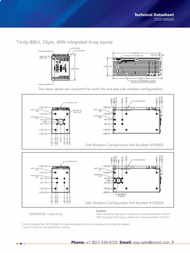
End Window Configuration Part Number 9100005
Side Window Configuration Part Number 9100004
Caution:*M5 mounting holes have a maximum screw penetration of 6mm.+M6 mounting holes have a maximum screw penetration of 8mm.
The views above are consistent for both the end and side window configurations.
Trinity 80kV, 33µm, 40W integrated X-ray source
Technical DatasheetDS9100004
Control Interface Box PN 9100006: An optional adapter for manual analog control may be ordered – useful for lab use and qualification testing
8 Oxford Instruments X-Ray Technology
90kv Microfocus X-ray SourceUltraBright 96000 Series
Target Material (Part#)
W (96004)
Mo (96002)
Cu (96000)
Voltage
10-90kV
20-60kV
20-60kV
Power
10-80W
20-60W
20-60W
Power Density
2.5W/µm
1.5 W/µm
1.5 W/µm
Product Ordering Table
X-RAY90kV Microfocus X-ray SourceUltraBright 96000 Series
Exceptional magnification and image quality
High power operation — ideal for high fluxapplications and experiments.
Integrated package eliminates HV cable forimproved reliability
Complete range of user control — ideal for research applications
Compact, lightweight design — ideal for portable applications
ApplicationsMicrotomography
Microdiffraction
Microfluorescence
CT imaging for life sciencesand industrial inspection
Technical Datasheet
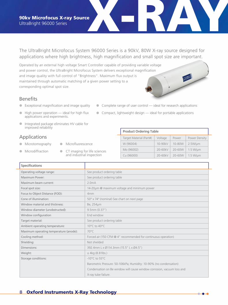
The UltraBright Microfocus System 96000 Series is a 90kV, 80W X-ray source designed forapplications where high brightness, high magnification and small spot size are important.
Operated by an external high voltage Smart Controller capable of providing variable voltage
and power control, the UltraBright Microfocus System delivers exceptional magnification
and image quality with full control of “Brightness”. Maximum flux output is
maintained through automatic matching of a given power setting to a
corresponding optimal spot size.
Specifications
Operating voltage range:
Maximum Power:
Maximum beam current:
Focal spot size:
Focus to Object Distance (FOD):
Cone of illumination:
Window material and thickness:
Window diameter (unobstructed):
Window configuration
Target material:
Ambient operating temperature:
Maximum operating temperature (anode):
Cooling method:
Shielding:
Dimensions:
Weight:
Storage conditions:
See product ordering table
See product ordering table
2.0mA
14-20µm @ maximum voltage and minimum power
4mm
50° x 74° (nominal) See chart on next page
Be, 254µm
9.5mm (0.37”)
End window
See product ordering table
10°C to 40°C
70°C
Forced air (150 CFM @ 4” recommended for continuous operation)
Not shielded
392.4mm L x Ø114.3mm (15.5” L x Ø4.5”)
≤ 4kg (8.81lbs.)
-10°C to 55°C
Barometric Pressure: 50-106kPa; Humidity: 10-90% (no condensation)
Condensation on Be window will cause window corrosion, vacuum loss and
X-ray tube failure.
Benefits
X-RAY
Phone: +1 (831) 439-9729 Email: [email protected] 9
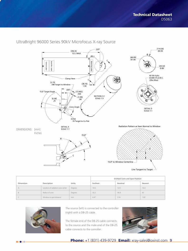
Technical DatasheetDS063
Dimension Description Units
Emitted Cone and Spot Position
Farthest Nominal Nearest
A
B
C
Location of radiation cone center
Radius of cone
Window to spot distance
Degrees
Degrees
mm
10.6
32.2
4.47
12.9
36.8
3.14
16.4
42
1.82
15.0° to Window Centerline
Radiation Pattern as Seen Normal to Window
A
B
C
DETAIL DSCALE 1:1
DETAIL ASCALE 1:1
SECTION C-CSCALE 1:3
Line Tangent to Target
�
�
UltraBright 96000 Series 90kV Microfocus X-ray Source
DIMENSIONS: [mm]Inches
The source (left) is connected to the controller
(right) with a DB-25 cable.
The female end of the DB-25 cable connects
to the source and the male end of the DB-25
cable connects to the conroller.
15.0°
[4.92]
[1.09]
[2.75]
[6.38]
[13.462]
[38.10]
[46.99]
[114.30]
[20.32]
Ø.600 [15.2] B.C.
[392.4]
.530
.04
1.50
Ø1.85
Ø4.50
(3lbs Max)
#2-56 4 plcs
Ø.80
15.5 MAX
225°
.25
.19 Target to Cu Flat
Cone Angle
15.0° Target Angle
.108 Target to Window
Clamp Here
Oxfo
rd Lab
el
Serial No
. Label
Warn
ing
Label
(30°)
A
C
C
X-RAY
10 Oxford Instruments X-Ray Technology
X-RAY90kv Microfocus X-ray SourceUltraBright 96000 Series (cont.)
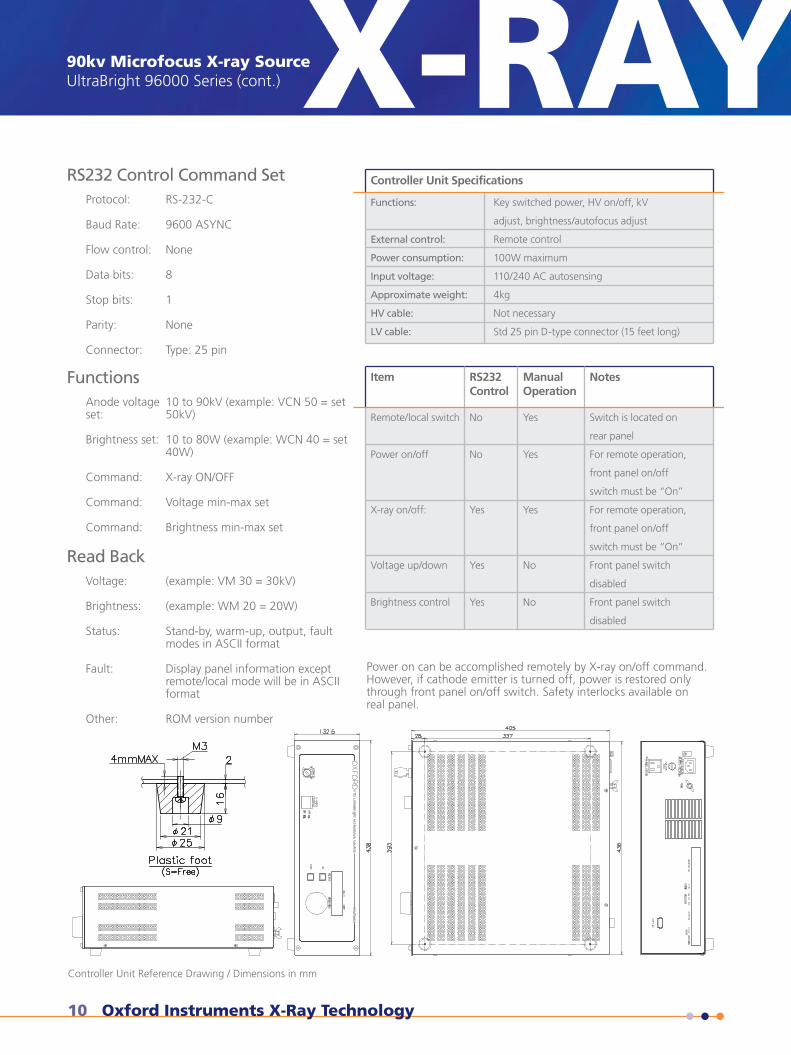
Controller Unit Specifications
Functions:
External control:
Power consumption:
Input voltage:
Approximate weight:
HV cable:
LV cable:
Key switched power, HV on/off, kV
adjust, brightness/autofocus adjust
Remote control
100W maximum
110/240 AC autosensing
4kg
Not necessary
Std 25 pin D-type connector (15 feet long)
Item RS232Control
Manual Operation
Notes
Remote/local switch
Power on/off
X-ray on/off:
Voltage up/down
Brightness control
No
No
Yes
Yes
Yes
Yes
Yes
Yes
No
No
Switch is located on
rear panel
For remote operation,
front panel on/off
switch must be “On”
For remote operation,
front panel on/off
switch must be “On”
Front panel switch
disabled
Front panel switch
disabled
X-RAY90kV Microfocus X-ray SourceUltraBright 96000 Series
RS232 Control Command SetProtocol: RS-232-C
Baud Rate: 9600 ASYNC
Flow control: None
Data bits: 8
Stop bits: 1
Parity: None
Connector: Type: 25 pin
FunctionsAnode voltage 10 to 90kV (example: VCN 50 = setset: 50kV)
Brightness set: 10 to 80W (example: WCN 40 = set 40W)
Command: X-ray ON/OFF
Command: Voltage min-max set
Command: Brightness min-max set
Read BackVoltage: (example: VM 30 = 30kV)
Brightness: (example: WM 20 = 20W)
Status: Stand-by, warm-up, output, fault modes in ASCII format
Fault: Display panel information except remote/local mode will be in ASCII format
Other: ROM version number
Power on can be accomplished remotely by X-ray on/off command.However, if cathode emitter is turned off, power is restored onlythrough front panel on/off switch. Safety interlocks available onreal panel.
Technical Datasheet
Controller Unit Reference DrawingDimensions in mm
Controller Unit Reference Drawing / Dimensions in mm
Phone: +1 (831) 439-9729 Email: [email protected] 11
X-RAY Technical DatasheetDS063
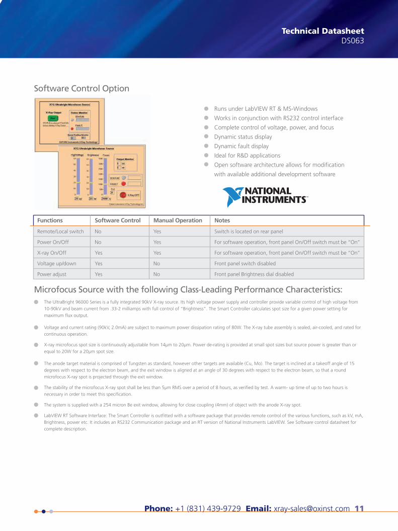
Functions
Remote/Local switch
Power On/Off
X-ray On/Off
Voltage up/down
Power adjust
Software Control
No
No
Yes
Yes
Yes
Manual Operation
Yes
Yes
Yes
No
No
Notes
Switch is located on rear panel
For software operation, front panel On/Off switch must be “On”
For software operation, front panel On/Off switch must be “On”
Front panel switch disabled
Front panel Brightness dial disabled
Software Control Option
Microfocus Source with the following Class-Leading Performance Characteristics:
X-ray Technology360 El Pueblo RoadScotts Valley, CA 95066, USA
Phone: +1 (831) 439-9729Fax: +1 (831) 439-6050Email: [email protected]
THE QUEEN'S AWARDS
FOR ENTERPRISE:
INNOVATION
2012
UltraBright 96000 Series 90kV Microfocus X-ray Source
Runs under LabVIEW RT & MS-Windows
Works in conjunction with RS232 control interface
Complete control of voltage, power, and focus
Dynamic status display
Dynamic fault display
Ideal for R&D applications
Open software architecture allows for modification
with available additional development software
The UltraBright 96000 Series is a fully integrated 90kV X-ray source. Its high voltage power supply and controller provide variable control of high voltage from 10-90kV and beam current from .33-2 milliamps with full control of “Brightness”. The Smart Controller calculates spot size for a given power setting for maximum flux output.
Voltage and current rating (90kV, 2.0mA) are subject to maximum power dissipation rating of 80W. The X-ray tube assembly is sealed, air-cooled, and rated for continuous operation.
X-ray microfocus spot size is continuously adjustable from 14µm to 20µm. Power de-rating is provided at small spot sizes but source power is greater than or equal to 20W for a 20µm spot size.
The anode target material is comprised of Tungsten as standard, however other targets are available (Cu, Mo). The target is inclined at a takeoff angle of 15 degrees with respect to the electron beam, and the exit window is aligned at an angle of 30 degrees with respect to the electron beam, so that a round microfocus X-ray spot is projected through the exit window.
The stability of the microfocus X-ray spot shall be less than 5µm RMS over a period of 8 hours, as verified by test. A warm- up time of up to two hours is necessary in order to meet this specification.
The system is supplied with a 254 micron Be exit window, allowing for close coupling (4mm) of object with the anode X-ray spot.
LabVIEW RT Software Interface: The Smart Controller is outfitted with a software package that provides remote control of the various functions, such as kV, mA, Brightness, power etc. It includes an RS232 Communication package and an RT version of National Instruments LabVIEW. See Software control datasheet for complete description.
This publication is the copyright of Oxford Instruments plc and provides outline information only, which (unless agreed by the company in writing) may not be used, applied or reproduced for any purpose or form part of any order or contract or regarded as the representa-tion relating to the products or services concerned. Oxford Instruments’ policy is one of continued improvement. The company reserves the right to alter, without notice the specification, design or conditions of supply of any product or service. Oxford Instruments acknowl-edges all trademarks and registrations. © Oxford Instruments plc, 2015. All rights reserved. Document reference: Part no: DS063 - June 4, 2015
visit www.oxford-instruments.com/xt or [email protected] for more information
12 Oxford Instruments X-Ray Technology
X-RAY90kv Water-Cooled Microfocus X-ray SourceNova 96000 Series
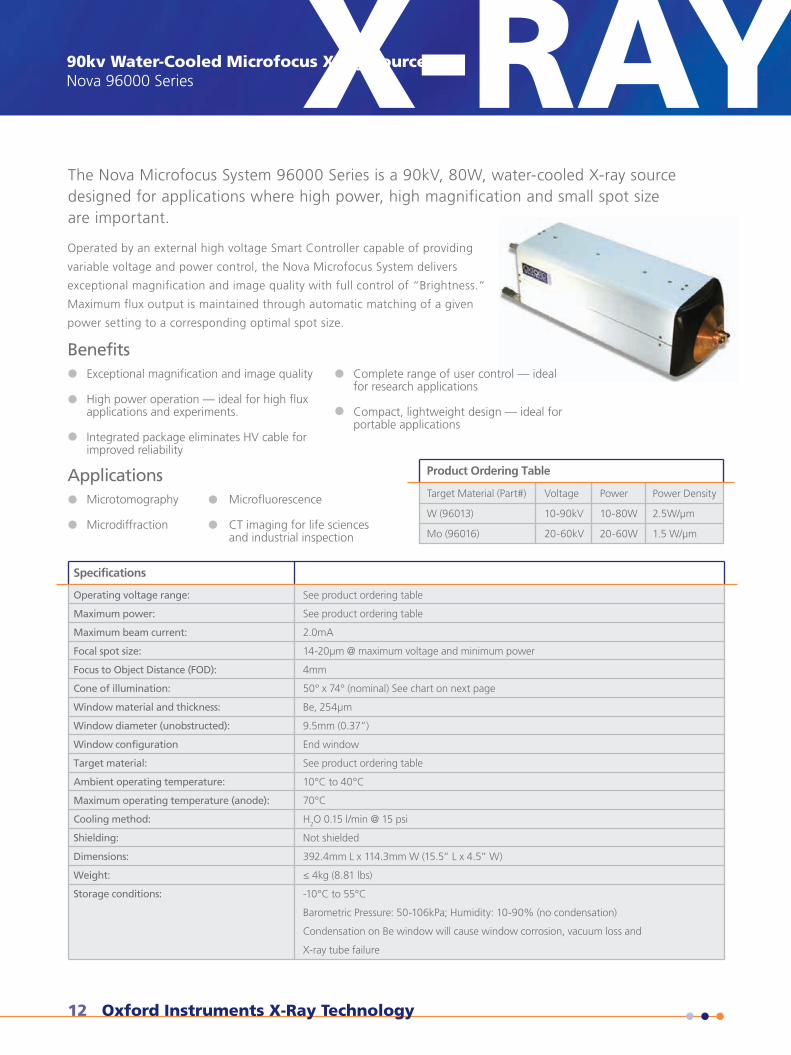
Target Material (Part#)
W (96013)
Mo (96016)
Voltage
10-90kV
20-60kV
Power
10-80W
20-60W
Power Density
2.5W/µm
1.5 W/µm
Product Ordering Table
X-RAY90kv Water-Cooled Microfocus X-ray SourceNova 96000 Series
Technical Datasheet
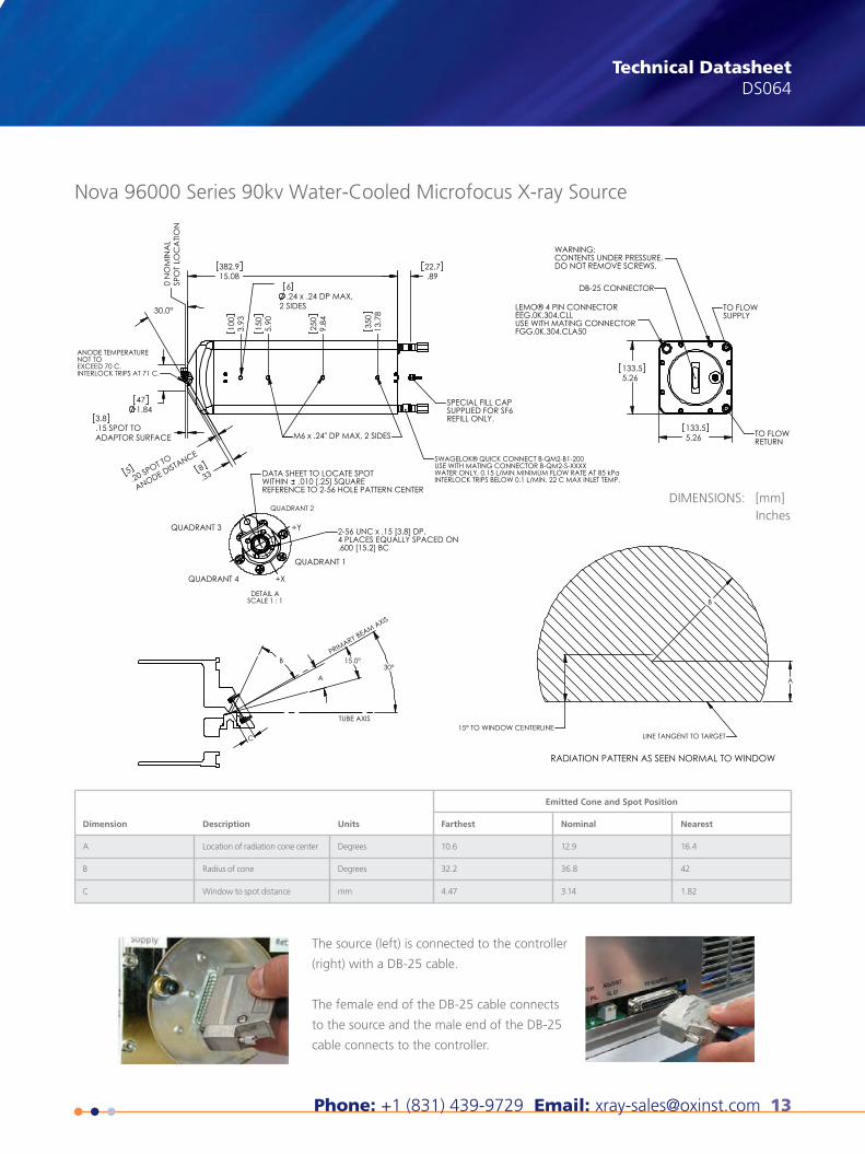
The Nova Microfocus System 96000 Series is a 90kV, 80W, water-cooled X-ray sourcedesigned for applications where high power, high magnification and small spot sizeare important.
Operated by an external high voltage Smart Controller capable of providing
variable voltage and power control, the Nova Microfocus System delivers
exceptional magnification and image quality with full control of “Brightness.”
Maximum flux output is maintained through automatic matching of a given
power setting to a corresponding optimal spot size.
BenefitsExceptional magnification and image quality
High power operation — ideal for high fluxapplications and experiments.
Integrated package eliminates HV cable forimproved reliability
Complete range of user control — idealfor research applications
Compact, lightweight design — ideal for portable applications
ApplicationsMicrotomography
Microdiffraction
Microfluorescence
CT imaging for life sciencesand industrial inspection
Specifications
Operating voltage range:
Maximum power:
Maximum beam current:
Focal spot size:
Focus to Object Distance (FOD):
Cone of illumination:
Window material and thickness:
Window diameter (unobstructed):
Window configuration
Target material:
Ambient operating temperature:
Maximum operating temperature (anode):
Cooling method:
Shielding:
Dimensions:
Weight:
Storage conditions:
See product ordering table
See product ordering table
2.0mA
14-20µm @ maximum voltage and minimum power
4mm
50° x 74° (nominal) See chart on next page
Be, 254µm
9.5mm (0.37”)
End window
See product ordering table
10°C to 40°C
70°C
H2O 0.15 l/min @ 15 psi
Not shielded
392.4mm L x 114.3mm W (15.5” L x 4.5” W)
≤ 4kg (8.81 lbs)
-10°C to 55°C
Barometric Pressure: 50-106kPa; Humidity: 10-90% (no condensation)
Condensation on Be window will cause window corrosion, vacuum loss and
X-ray tube failure
Phone: +1 (831) 439-9729 Email: [email protected] 13
X-RAY Technical DatasheetDS064
Dimension Description Units
Emitted Cone and Spot Position
Farthest Nominal Nearest
A
B
C
Location of radiation cone center
Radius of cone
Window to spot distance
Degrees
Degrees
mm
10.6
32.2
4.47
12.9
36.8
3.14
16.4
42
1.82
15.08382.9
30.0°
.24 x .24 DP MAX, 2 SIDES
6.89
22.7
1.8447
0 N
OM
INA
LSP
OT
LOC
ATIO
N
3.93
100
5.90
150
9.84
250
13.7
835
0
.338
.15 SPOT TOADAPTOR SURFACE
3.8
.20 SPOT TO
ANODE DISTANCE
5
ANODE TEMPERATURE NOT TOEXCEED 70 C.INTERLOCK TRIPS AT 71 C.
M6 x .24" DP MAX, 2 SIDES
SWAGELOK® QUICK CONNECT B-QM2-B1-200USE WITH MATING CONNECTOR B-QM2-S-XXXXWATER ONLY, 0.15 L/MIN MINIMUM FLOW RATE AT 85 kPaINTERLOCK TRIPS BELOW 0.1 L/MIN, 22 C MAX INLET TEMP.
SPECIAL FILL CAP SUPPLIED FOR SF6 REFILL ONLY.
DETAIL ASCALE 1 : 1
+X
QUADRANT 3
QUADRANT 4
DATA SHEET TO LOCATE SPOTWITHIN .010 [.25] SQUAREREFERENCE TO 2-56 HOLE PATTERN CENTER
2-56 UNC x .15 [3.8] DP,4 PLACES EQUALLY SPACED ON.600 [15.2] BC
QUADRANT 2
+Y
QUADRANT 1
5.26133.5
5.26133.5
WARNING: CONTENTS UNDER PRESSURE. DO NOT REMOVE SCREWS.
DB-25 CONNECTOR
TO FLOW SUPPLY
TO FLOW RETURN
LEMO® 4 PIN CONNECTOR EEG.0K.304.CLLUSE WITH MATING CONNECTOR FGG.0K.304.CLA50
15.0°
A
B
15° TO WINDOW CENTERLINE
A
B
C
30°
LINE TANGENT TO TARGET
RADIATION PATTERN AS SEEN NORMAL TO WINDOW
PRIMARY BEAM AXIS
TUBE AXIS
Nova 96000 Series 90kv Water-Cooled Microfocus X-ray Source
DIMENSIONS: [mm]Inches
The source (left) is connected to the controller
(right) with a DB-25 cable.
The female end of the DB-25 cable connects
to the source and the male end of the DB-25
cable connects to the controller.
14 Oxford Instruments X-Ray Technology
X-RAY90kv Water-Cooled Microfocus X-ray SourceNova 96000 Series (cont.)
90kv Water-Cooled Mi-crofocus X-ray SourceNova 96000 Series
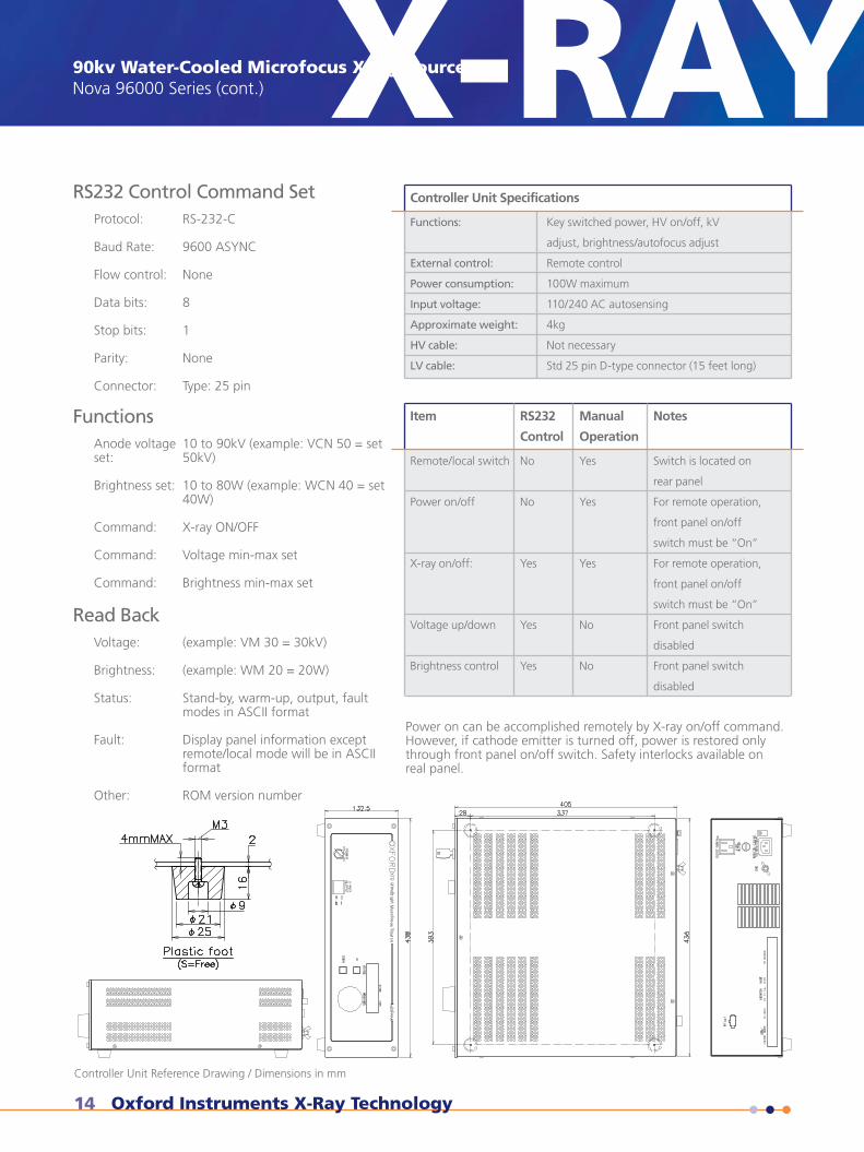
Controller Unit Specifications
Functions:
External control:
Power consumption:
Input voltage:
Approximate weight:
HV cable:
LV cable:
Key switched power, HV on/off, kV
adjust, brightness/autofocus adjust
Remote control
100W maximum
110/240 AC autosensing
4kg
Not necessary
Std 25 pin D-type connector (15 feet long)
Item RS232
Control
Manual
Operation
Notes
Remote/local switch
Power on/off
X-ray on/off:
Voltage up/down
Brightness control
No
No
Yes
Yes
Yes
Yes
Yes
Yes
No
No
Switch is located on
rear panel
For remote operation,
front panel on/off
switch must be “On”
For remote operation,
front panel on/off
switch must be “On”
Front panel switch
disabled
Front panel switch
disabled
RS232 Control Command SetProtocol: RS-232-C
Baud Rate: 9600 ASYNC
Flow control: None
Data bits: 8
Stop bits: 1
Parity: None
Connector: Type: 25 pin
FunctionsAnode voltage 10 to 90kV (example: VCN 50 = setset: 50kV)
Brightness set: 10 to 80W (example: WCN 40 = set 40W)
Command: X-ray ON/OFF
Command: Voltage min-max set
Command: Brightness min-max set
Read BackVoltage: (example: VM 30 = 30kV)
Brightness: (example: WM 20 = 20W)
Status: Stand-by, warm-up, output, fault modes in ASCII format
Fault: Display panel information except remote/local mode will be in ASCII format
Other: ROM version number
Power on can be accomplished remotely by X-ray on/off command.However, if cathode emitter is turned off, power is restored onlythrough front panel on/off switch. Safety interlocks available onreal panel.
90kv Water-Cooled Microfocus X-ray SourceNova 96000 Series
Technical Datasheet
Controller Unit Reference DrawingDimensions in mm
X-RAY
Controller Unit Reference Drawing / Dimensions in mm
Phone: +1 (831) 439-9729 Email: [email protected] 15
X-RAY Technical DatasheetDS064
Functions
Remote/Local switch
Power On/Off
X-ray On/Off
Voltage up/down
Power adjust
Software Control
No
No
Yes
Yes
Yes
Manual Operation
Yes
Yes
Yes
No
No
Notes
Switch is located on rear panel
For software operation, front panel On/Off switch must be “On”
For software operation, front panel On/Off switch must be “On”
Front panel switch disabled
Front panel Brightness dial disabled
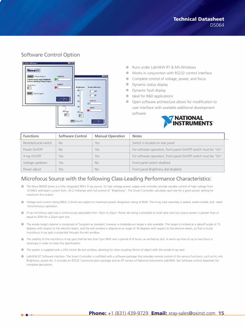
Software Control Option
Microfocus Source with the following Class-Leading Performance Characteristics:
X-ray Technology360 El Pueblo RoadScotts Valley, CA 95066, USA
Phone: +1 (831) 439-9729Fax: +1 (831) 439-6050Email: [email protected]
THE QUEEN'S AWARDS
FOR ENTERPRISE:
INNOVATION
2012
Runs under LabVIEW RT & MS-Windows
Works in conjunction with RS232 control interface
Complete control of voltage, power, and focus
Dynamic status display
Dynamic fault display
Ideal for R&D applications
Open software architecture allows for modification to
user interface with available additional development
software
The Nova 96000 Series is a fully integrated 90kV X-ray source. Its high voltage power supply and controller provide variable control of high voltage from 10-90kV and beam current from .33-2 milliamps with full control of “Brightness”. The Smart Controller calculates spot size for a given power setting for maximum flux output.
Voltage and current rating (90kV, 2.0mA) are subject to maximum power dissipation rating of 80W. The X-ray tube assembly is sealed, water-cooled, and rated for continuous operation.
X-ray microfocus spot size is continuously adjustable from 14µm to 20µm. Power de-rating is provided at small spot sizes but source power is greater than or equal to 20W for a 20µm spot size.
The anode target material is comprised of Tungsten as standard, however a molybdenum target is also available. The target is inclined at a takeoff angle of 15 degrees with respect to the electron beam, and the exit window is aligned at an angle of 30 degrees with respect to the electron beam, so that a round microfocus X-ray spot is projected through the exit window.
The stability of the microfocus X-ray spot shall be less than 5µm RMS over a period of 8 hours, as verified by test. A warm-up time of up to two hours is necessary in order to meet this specification.
The system is supplied with a 254 micron Be exit window, allowing for close coupling (4mm) of object with the anode X-ray spot.
LabVIEW RT Software Interface: The Smart Controller is outfitted with a software package that provides remote control of the various functions, such as kV, mA, Brightness, power etc. It includes an RS232 Communication package and an RT version of National Instruments LabVIEW. See Software control datasheet for complete description.
Nova 96000 Series 90kv Water-Cooled Microfocus X-ray Source
This publication is the copyright of Oxford Instruments plc and provides outline information only, which (unless agreed by the company in writing) may not be used, applied or reproduced for any purpose or form part of any order or contract or regarded as the representa-tion relating to the products or services concerned. Oxford Instruments’ policy is one of continued improvement. The company reserves the right to alter, without notice the specification, design or conditions of supply of any product or service. Oxford Instruments acknowl-edges all trademarks and registrations. © Oxford Instruments plc, 2015. All rights reserved. Document reference: Part no: DS064 - June 22, 2015
visit www.oxford-instruments.com/xt or [email protected] for more information
16 Oxford Instruments X-Ray Technology
X-RAY50kV Microfocus X-ray SourcePinnacles 50kV X-RAY50kV Microfocus X-ray SourcePinnacles 50kV
Technical Datasheet
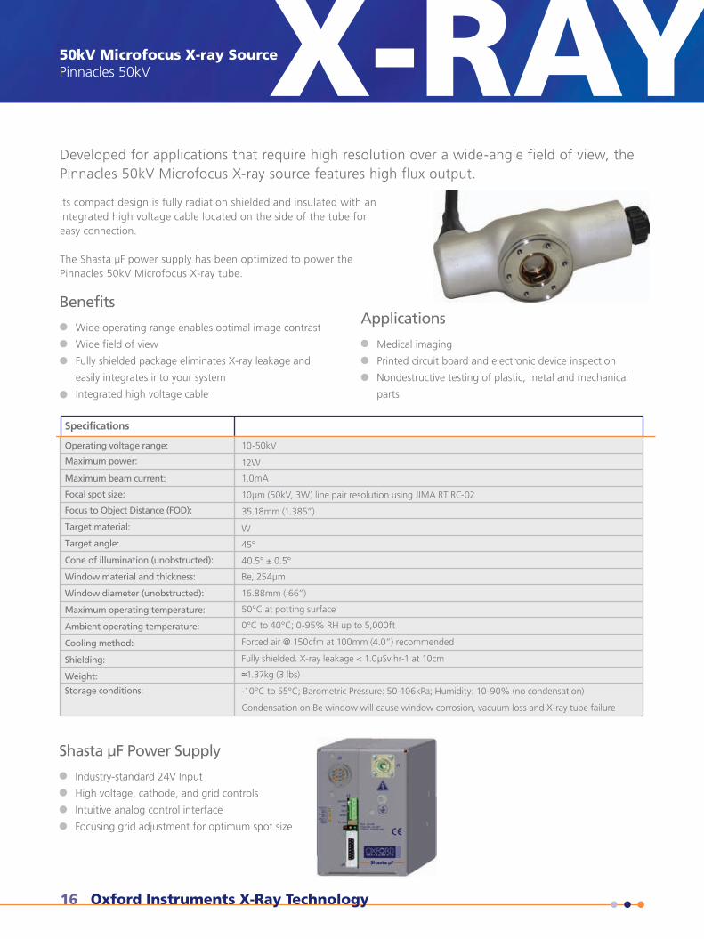
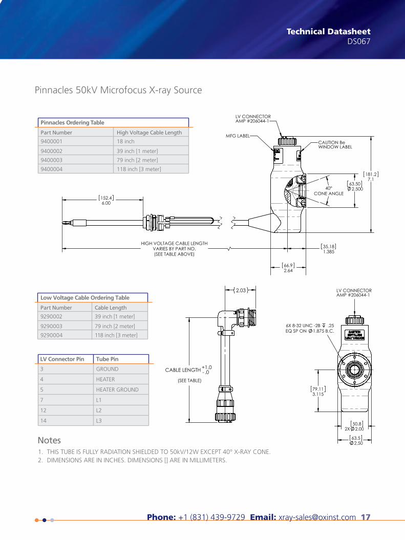
Developed for applications that require high resolution over a wide-angle field of view, thePinnacles 50kV Microfocus X-ray source features high flux output.
Wide operating range enables optimal image contrast
Wide field of view
Fully shielded package eliminates X-ray leakage and
easily integrates into your system
Integrated high voltage cable
Applications
Medical imaging
Printed circuit board and electronic device inspection
Nondestructive testing of plastic, metal and mechanical
parts
Specifications
Operating voltage range:
Maximum power:
Maximum beam current:
Focal spot size:
Focus to Object Distance (FOD):
Target material:
Target angle:
Cone of illumination (unobstructed):
Window material and thickness:
Window diameter (unobstructed):
Maximum operating temperature:
Ambient operating temperature:
Cooling method:
Shielding:
Weight:
Storage conditions:
10-50kV
12W
1.0mA
10µm (50kV, 3W) line pair resolution using JIMA RT RC-02
35.18mm (1.385”)
W
45°
40.5° ± 0.5°
Be, 254µm
16.88mm (.66”)
50°C at potting surface
0°C to 40°C; 0-95% RH up to 5,000ft
Forced air @ 150cfm at 100mm (4.0”) recommended
Fully shielded. X-ray leakage < 1.0µSv.hr-1 at 10cm
≈1.37kg (3 lbs)
-10°C to 55°C; Barometric Pressure: 50-106kPa; Humidity: 10-90% (no condensation)
Condensation on Be window will cause window corrosion, vacuum loss and X-ray tube failure
Shasta µF Power Supply
Industry-standard 24V Input
High voltage, cathode, and grid controls
Intuitive analog control interface
Focusing grid adjustment for optimum spot size
Benefits
Its compact design is fully radiation shielded and insulated with an integrated high voltage cable located on the side of the tube for easy connection.
The Shasta µF power supply has been optimized to power the Pinnacles 50kV Microfocus X-ray tube.
Phone: +1 (831) 439-9729 Email: [email protected] 17
Technical DatasheetDS067X-RAY
THIS TUBE IS FULLY RADIATION SHIELDED TO 50kV/12W EXCEPT 40° X-RAY CONE.DIMENSIONS ARE IN INCHES. DIMENSIONS [] ARE IN MILLIMETERS.
1.2.
Notes
LV Connector Pin Tube Pin
3
4
5
7
12
14
GROUND
HEATER
HEATER GROUND
L1
L2
L3
Pinnacles Ordering Table
Part Number
9400001
9400002
9400003
9400004
High Voltage Cable Length
18 inch
39 inch [1 meter]
79 inch [2 meter]
118 inch [3 meter]
Low Voltage Cable Ordering Table
Part Number
9290002
9290003
9290004
Cable Length
39 inch [1 meter]
79 inch [2 meter]
118 inch [3 meter]
X-ray Technology360 El Pueblo RoadScotts Valley, CA 95066, USA
Phone: +1 (831) 439-9729Fax: +1 (831) 439-6050Email: [email protected]
THE QUEEN'S AWARDS
FOR ENTERPRISE:
INNOVATION
2012
Pinnacles 50kV Microfocus X-ray Source
63.502.500
66.92.64
152.46.00
35.181.385
HIGH VOLTAGE CABLE LENGTHVARIES BY PART NO.(SEE TABLE ABOVE)
181.27.1
40°CONE ANGLE
CAUTION BeWINDOW LABEL
MFG LABEL
LV CONNECTORAMP #206044-1
63.52.50
2X50.8
2.00
6X 8-32 UNC -2B .25EQ SP ON 1.875 B.C.
79.113.115
CABLE LENGTH +-1.0.0
2.03
(SEE TABLE)
LV CONNECTORAMP #206044-1
This publication is the copyright of Oxford Instruments plc and provides outline information only, which (unless agreed by the company in writing) may not be used, applied or reproduced for any purpose or form part of any order or contract or regarded as the representa-tion relating to the products or services concerned. Oxford Instruments’ policy is one of continued improvement. The company reserves the right to alter, without notice the specification, design or conditions of supply of any product or service. Oxford Instruments acknowl-edges all trademarks and registrations. © Oxford Instruments plc, 2014. All rights reserved. Document reference: Part no: DS067 - August 7, 2014
visit www.oxford-instruments.com/xt or [email protected] for more information
18 Oxford Instruments X-Ray Technology
Water-Cooled Radiation Shielded X-ray TubeNeptune 5200 Series X-RAYX-RAYWater-Cooled Radiation Shielded X-ray TubeNeptune 5200 Series
Technical Datasheet
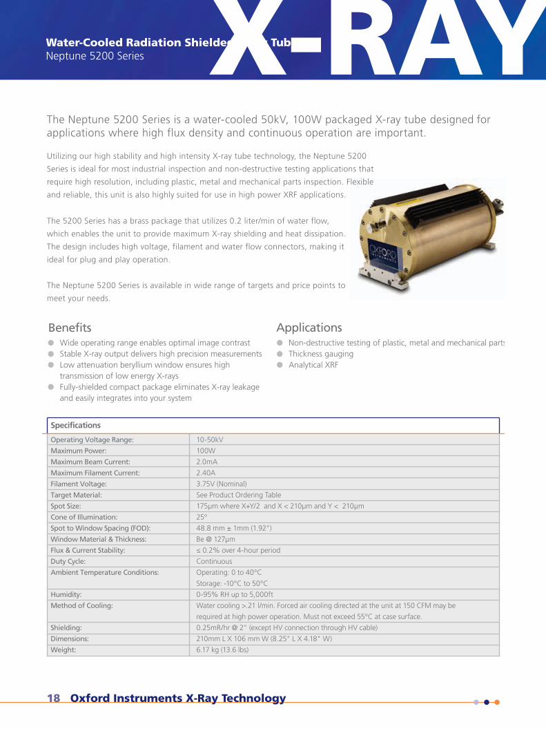
Wide operating range enables optimal image contrastStable X-ray output delivers high precision measurementsLow attenuation beryllium window ensures hightransmission of low energy X-raysFully-shielded compact package eliminates X-ray leakageand easily integrates into your system
Non-destructive testing of plastic, metal and mechanical partsThickness gaugingAnalytical XRF
Applications
Specifications
Operating Voltage Range:
Maximum Power:
Maximum Beam Current:
Maximum Filament Current:
Filament Voltage:
Target Material:
Spot Size:
Cone of Illumination:
Spot to Window Spacing (FOD):
Window Material & Thickness:
Flux & Current Stability:
Duty Cycle:
Ambient Temperature Conditions:
Humidity:
Method of Cooling:
Shielding:
Dimensions:
Weight:
10-50kV
100W
2.0mA
2.40A
3.75V (Nominal)
See Product Ordering Table
175µm where X+Y/2 and X < 210µm and Y < 210µm
25°
48.8 mm ± 1mm (1.92")
Be @ 127µm
≤ 0.2% over 4-hour period
Continuous
Operating: 0 to 40°C
Storage: -10°C to 50°C
0-95% RH up to 5,000ft
Water cooling >.21 l/min. Forced air cooling directed at the unit at 150 CFM may be
required at high power operation. Must not exceed 55°C at case surface.
0.25mR/hr @ 2" (except HV connection through HV cable)
210mm L X 106 mm W (8.25" L X 4.18" W)
6.17 kg (13.6 lbs)
Benefits
The Neptune 5200 Series is a water-cooled 50kV, 100W packaged X-ray tube designed for applications where high flux density and continuous operation are important.
Utilizing our high stability and high intensity X-ray tube technology, the Neptune 5200
Series is ideal for most industrial inspection and non-destructive testing applications that
require high resolution, including plastic, metal and mechanical parts inspection. Flexible
and reliable, this unit is also highly suited for use in high power XRF applications.
The 5200 Series has a brass package that utilizes 0.2 liter/min of water flow,
which enables the unit to provide maximum X-ray shielding and heat dissipation.
The design includes high voltage, filament and water flow connectors, making it
ideal for plug and play operation.
The Neptune 5200 Series is available in wide range of targets and price points to
meet your needs.
Phone: +1 (831) 439-9729 Email: [email protected] 19
X-RAY Technical DatasheetDS5200
visit www.oxford-instruments.com/xt or [email protected] for more information
This publication is the copyright of Oxford Instruments plc and provides outline information only, which (unless agreed by the company in writing) may not be used, applied or reproduced for any purpose or form part of any order or contract or regarded as the representa-tion relating to the products or services concerned. Oxford Instruments’ policy is one of continued improvement. The company reserves the right to alter, without notice the specification, design or conditions of supply of any product or service. Oxford Instruments acknowl-edges all trademarks and registrations. © Oxford Instruments plc, 2015. All rights reserved. Document reference: Part no: DS5200 - February 5, 2015
X-ray Technology360 El Pueblo RoadScotts Valley, CA 95066, USA
Phone: +1 (831) 439-9729Fax: +1 (831) 439-6050Email: [email protected]
THE QUEEN'S AWARDS
FOR ENTERPRISE:
INNOVATION
2012
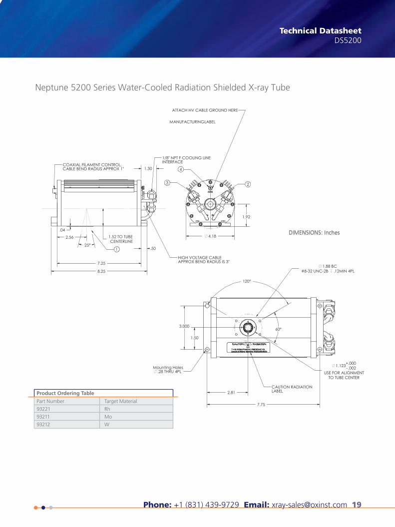
Neptune 5200 Series Water-Cooled Radiation Shielded X-ray Tube
Product Ordering Table
Part Number
93221
93211
93212
Target Material
Rh
Mo
W
DIMENSIONS: Inches
20 Oxford Instruments X-Ray Technology
X-RAYRadiation Shielded X-ray TubeJupiter 5000 Series
SpecificationsOperating Voltage Range:
Maximum Power:
Maximum Beam Current:
Focal spot size:
Maximum Filament Current:
Filament Voltage:
Focus to Object Distance (FOD):
Window material and thickness:
Cone of illumination (unobstructed):
Window diameter (unobstructed):
Target material:
Target angle:
Stability:
Polarity:
Maximum operating temperature:
Ambient operating temperature:
Cooling method
Shielding:
Dimensions:
Weight:
Storage Conditions:
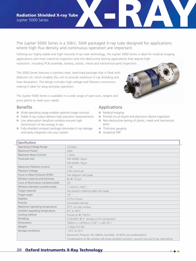
10-50kV
50W
1.0mA
P/N 93089: 50µm
P/N 93095: 55µm
1.7A
2.0V (nominal)
See diagram next page
Be @ 127µm
23°
11.43mm (.450”)
See product ordering table next page
12°
0.2% 4 hours
Grounded cathode
55°C on case surface
0°C to 40°C
Forced air @ 150cfm
0.25mR/hr @ 2” (except at HV connection)
180mm L x Ø70mm (7.09” L x Ø2.76”)
2.26kg (5.0 lbs)
-10°C to 55°C
Barometric Pressure: 50-106kPa; Humidity: 10-90% (no condensation)
Condensation on Be window will cause window corrosion, vacuum loss and X-ray tube failure
Radiation Shielded X-ray TubeJupiter 5000 Series
Technical Datasheet
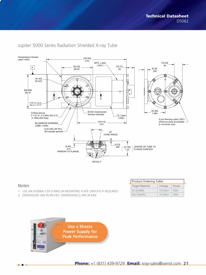
The Jupiter 5000 Series is a 50kV, 50W packaged X-ray tube designed for applicationswhere high flux density and continuous operation are important.
Utilizing our highly stable and high intensity X-ray tube technology, the Jupiter 5000 Series is ideal for medical imaging
applications and most industrial inspection and non-destructive testing applications that require high
resolution, including PCB assembly, battery, plastic, metal and mechanical parts inspection.
The 5000 Series features a stainless steel, lead-lined package that is filled with
dielectric oil, which enables the unit to provide maximum X-ray shielding and
heat dissipation. The design includes high voltage and filament connectors,
making it ideal for plug and play operation.
The Jupiter 5000 Series is available in a wide range of spot sizes, targets and
price points to meet your needs.
X-RAY
Wide operating range enables optimal image contrastStable X-ray output delivers high precision measurementsLow attenuation beryllium window ensures hightransmission of low energy X-raysFully-shielded compact package eliminates X-ray leakageand easily integrates into your system
Medical ImagingPrinted circuit board and electronic device inspectionNon-destructive testing of plastic, metal and mechanicalparts
Thickness gaugingAnalytical XRF
ApplicationsBenefits
Phone: +1 (831) 439-9729 Email: [email protected] 21
Technical DatasheetDS062X-RAY
visit www.oxford-instruments.com/xt or [email protected] for more information
Product Ordering Table
Target Material Voltage Power
W (93089)
Mo (93095)
10-50kV
10-50kV
50W
50WUSE AN AS568A-139 O-RING IN MOUNTING PLATE GROOVE IF REQUIREDDIMENSIONS ARE IN INCHES. DIMENSIONS [] ARE IN MM
1.2.
Notes
X-ray Technology360 El Pueblo RoadScotts Valley, CA 95066, USA
Phone: +1 (831) 439-9729Fax: +1 (831) 439-6050Email: [email protected]
THE QUEEN'S AWARDS
FOR ENTERPRISE:
INNOVATION
2012
Jupiter 5000 Series Radiation Shielded X-ray Tube
This publication is the copyright of Oxford Instruments plc and provides outline information only, which (unless agreed by the company in writing) may not be used, applied or reproduced for any purpose or form part of any order or contract or regarded as the representa-tion relating to the products or services concerned. Oxford Instruments’ policy is one of continued improvement. The company reserves the right to alter, without notice the specification, design or conditions of supply of any product or service. Oxford Instruments acknowl-edges all trademarks and registrations. © Oxford Instruments plc, 2015. All rights reserved. Document reference: Part no: DS062 - June 25, 2015
A
A
E E
X-ray Warning Label (1901)(Place as close as possibleto connector end)
[163.60]
[63.50]
[47.63]
[69.850]
6.44
[16.31].64
Label (1420)Temperature Indicator
O-Ring Groove2.115 I.D. X 2.385±.002 O.D..X .080±.002 Deep
Be WINDOW WARNINGLABEL (1426)
8-32 UNC-2B Thru(6X equally spaced)
Ø.450 UnobstructedWindow Diameter I.D. Label
(1002)
Ø1.875
Ø2.75
5°
Ø2.50
[100.74]3.97
23°CONE ANGLE
MFG. Label(1001)
[0.23].009
[42.80]
CENTER OF TUBE TOFLANGE SURFACE
DETAIL F
WINDOW TO FLANGE
1.685
[6.35].250
[31.05]1.22
[5.44].214
[16.26].64
Use a ShastaPower Supply forPeak Performance
22 Oxford Instruments X-Ray Technology
Radiation Shielded X-ray TubeApogee 5500 Series X-RAY
Specifications
Operating Voltage Range:
Maximum Power:
Maximum Beam Current:
Grid Voltage:
Maximum Filament Current:
Filament Voltage:
Target Material:
Focal Spot Size:
Cone of Illumination:
Spot to Window Spacing (FOD):
Window Material and Thickness:
Flux and Current Stability:
Duty Cycle:
Ambient Temperature Conditions:
Humidity:
Cooling Method:
Shielding:
Dimensions:
Weight:
10-50kV
50W
1.0mA
0-100V (Oxford Shasta Power Supply recommended)
1.7A
2.0V (Nominal)
See product ordering table on next page
35µm *nominal per IEC60336, NEMA XR5-1992 (R1999)
22°
31.05mm ±1mm
Be @ 127µm
≤ 0.2% over 4-hour period
Continuous (150 CFM airflow required)
Operating: 0 to 40°C
Storage: -10°C to 50°C
0-95% RH up to 5,000 feet
External cooling required and directed at the unit at 150 CFM. Must not exceed 55°C
at case surface.
0.25mR/hr @ 2" (except HV connection through HV cable)
180mm L X Ø70mm (7.09" L X Ø2.76")
1.82kg (4.0 lbs)
Radiation Shielded X-ray TubeApogee 5500 Series
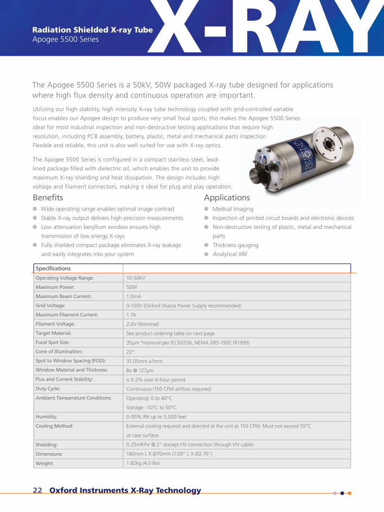
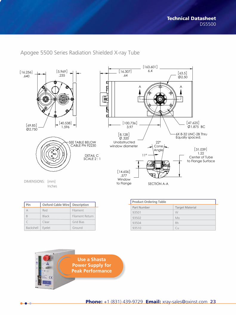
The Apogee 5500 Series is a 50kV, 50W packaged X-ray tube designed for applicationswhere high flux density and continuous operation are important.
Utilizing our high stability, high intensity X-ray tube technology coupled with grid-controlled variable
focus enables our Apogee design to produce very small focal spots; this makes the Apogee 5500 Series
ideal for most industrial inspection and non-destructive testing applications that require high
resolution, including PCB assembly, battery, plastic, metal and mechanical parts inspection.
Flexible and reliable, this unit is also well suited for use with X-ray optics.
The Apogee 5500 Series is configured in a compact stainless steel, lead-
lined package filled with dielectric oil, which enables the unit to provide
maximum X-ray shielding and heat dissipation. The design includes high
voltage and filament connectors, making it ideal for plug and play operation.
Applications
Technical DatasheetX-RAY
Benefits
Stable X-ray output delivers high-precision measurements
Wide operating range enables optimal image contrast
Low attenuation beryllium window ensures high
transmission of low energy X-rays
and easily integrates into your system
Fully shielded compact package eliminates X-ray leakage
Inspection of printed circuit boards and electronic devices
Medical Imaging
Non-destructive testing of plastic, metal and mechanical
parts
Analytical XRF
Thickness gauging
Phone: +1 (831) 439-9729 Email: [email protected] 23
X-RAY Technical DatasheetDS5500
Use a ShastaPower Supply forPeak Performance
visit www.oxford-instruments.com/xt or [email protected] for more information
Product Ordering Table
Part Number
93501
93502
93504
93510
Target Material
W
Mo
Rh
Cu
Pin Oxford Cable Wire
A
B
C
Backshell
Red
Black
Clear
Eyelet
Description
Filament
Filament Return
Grid Bias
Ground
DIMENSIONS: [mm]Inches
X-ray Technology360 El Pueblo RoadScotts Valley, CA 95066, USA
Phone: +1 (831) 439-9729Fax: +1 (831) 439-6050Email: [email protected]
THE QUEEN'S AWARDS
FOR ENTERPRISE:
INNOVATION
2012
Apogee 5500 Series Radiation Shielded X-ray Tube
This publication is the copyright of Oxford Instruments plc and provides outline information only, which (unless agreed by the company in writing) may not be used, applied or reproduced for any purpose or form part of any order or contract or regarded as the representa-tion relating to the products or services concerned. Oxford Instruments’ policy is one of continued improvement. The company reserves the right to alter, without notice the specification, design or conditions of supply of any product or service. Oxford Instruments acknowl-edges all trademarks and registrations. © Oxford Instruments plc, 2015. All rights reserved. Document reference: Part no: DS5500 - June 25, 2015
.64016.256
.2355.969
1.59640.538
2.75069.85
C
6.4163.601
.6416.307
2.5063.5
3.97100.736
8.128.320
Unobstructedwindow diameter
1.875 BC47.625
A A
6X 8-32 UNC-2B ThruEqually spaced.
1.22Center of Tube
to Flange Surface
31.039
.577Window
to Flange
14.656
11°
22°ConeAngle
SECTION A-A
DETAIL C SCALE 2 : 1
SEE TABLE BELOWCABLE PN 92230
24 Oxford Instruments X-Ray Technology
30kV X-ray Tube3000 Series X-RAYX-RAY30kV X-ray Tube3000 Series
Technical Datasheet
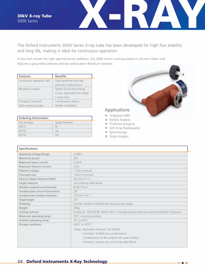
The Oxford Instruments 3000 Series X-ray tube has been developed for high flux stabilityand long life, making it ideal for continuous operation.
A low cost answer for high spectral purity radiation, the 3000 Series is encapsulated in silicone rubber and
features a grounded cathode and low attenuation Beryllium window.
Analytical (XRF)Particle AnalysisThickness GaugingSoft X-ray RadiographySpectroscopyStress Analysis
Applications
Specifications
Operating Voltage Range:
Maximum power:
Maximum beam current:
Maximum filament current:
Filament voltage:
Focal spot size:
Focus to Object Distance (FOD):
Target material:
Window material and thickness:
Unobstructed cone of illumination:
Unobstructed window diameter:
Target angle:
Shielding:
Weight:
Cooling method:
Maximum operating temp:
Ambient operating temp:
Storage conditions:
4-30kV
9W
0.3mA
2.0A
1.75V (nominal)
1.0mm (nominal)
28.2mm (1.1”)
See ordering table above
Be @ 127µm
28°
10.4mm (.41”)
20°
Partially radiation shielded (see drawing next page)
260g
Forced air: 150CFM @ 100mm (4.0”) and appropriate heat sink recommended for full power
50°C at potting surface
0°C to 40°C
-40°C to 70°C*
*Note: Barometric Pressure: 50-106kPa
Humidity: 10-90% (no condensation)
Condensation on Be window will cause window
corrosion, vacuum loss, and X-ray tube failure
Features BenefitsContinuous operation: 9W
Beryllium window
Compact, insulated
light-weight package
High sensitivity and high
precision measurement
Higher flux of low-energy
X-rays, especially from target
L series lines
Configuration allows
flexible installation
Ordering InformationPart Number
90151
90152
90153
Target Material
Rh
Ag
Mo
Phone: +1 (831) 439-9729 Email: [email protected] 25
X-RAY Technical DatasheetDS059
visit www.oxford-instruments.com/xt or [email protected] for more information
X-ray Technology360 El Pueblo RoadScotts Valley, CA 95066, USA
Phone: +1 (831) 439-9729Fax: +1 (831) 439-6050Email: [email protected]
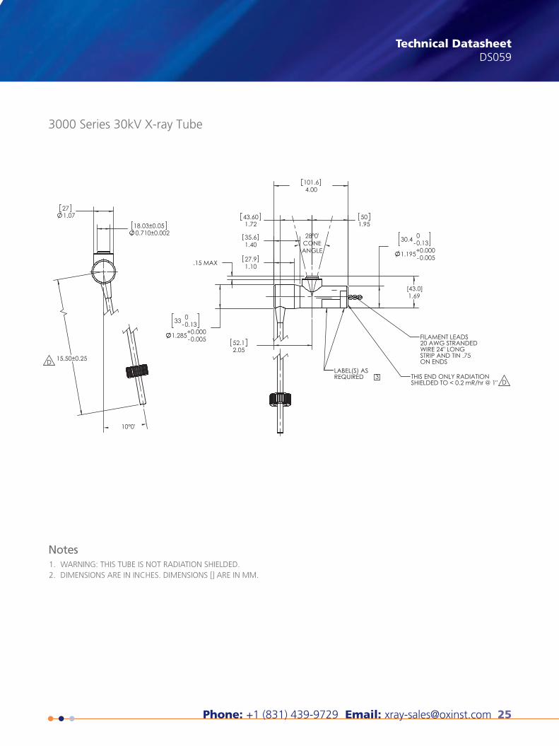
3000 Series 30kV X-ray Tube
WARNING: THIS TUBE IS NOT RADIATION SHIELDED.DIMENSIONS ARE IN INCHES. DIMENSIONS [] ARE IN MM.
1.2.
Notes
THE QUEEN'S AWARDS
FOR ENTERPRISE:
INNOVATION
2012
This publication is the copyright of Oxford Instruments plc and provides outline information only, which (unless agreed by the company in writing) may not be used, applied or reproduced for any purpose or form part of any order or contract or regarded as the representa-tion relating to the products or services concerned. Oxford Instruments’ policy is one of continued improvement. The company reserves the right to alter, without notice the specification, design or conditions of supply of any product or service. Oxford Instruments acknowl-edges all trademarks and registrations. © Oxford Instruments plc, 2015. All rights reserved. Document reference: Part no: DS059 - February 5, 2015
26 Oxford Instruments X-Ray Technology
Glass X-ray Tube1000 Series - 90507 X-RAYX-RAYGlass X-ray Tube1000 Series - 90507
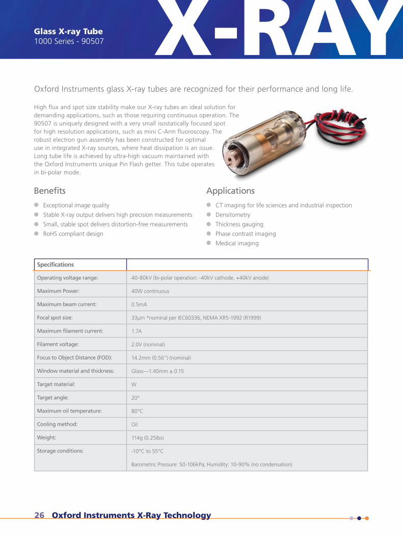
Exceptional image quality
Stable X-ray output delivers high precision measurements
Small, stable spot delivers distortion-free measurements
RoHS compliant design
Specifications
Operating voltage range:
Maximum Power:
Maximum beam current:
Focal spot size:
Maximum filament current:
Filament voltage:
Focus to Object Distance (FOD):
Window material and thickness:
Target material:
Target angle:
Maximum oil temperature:
Cooling method:
Weight:
Storage conditions:
Technical Datasheet
Oxford Instruments glass X-ray tubes are recognized for their performance and long life.
High flux and spot size stability make our X-ray tubes an ideal solution fordemanding applications, such as those requiring continuous operation. The90507 is uniquely designed with a very small isostatically focused spotfor high resolution applications, such as mini C-Arm fluoroscopy. Therobust electron gun assembly has been constructed for optimaluse in integrated X-ray sources, where heat dissipation is an issue.Long tube life is achieved by ultra-high vacuum maintained withthe Oxford Instruments unique Pin Flash getter. This tube operatesin bi-polar mode.
CT imaging for life sciences and industrial inspection
Densitometry
Thickness gauging
Phase contrast imaging
Medical imaging
40-80kV (bi-polar operation: -40kV cathode, +40kV anode)
40W continuous
0.5mA
33µm *nominal per IEC60336, NEMA XR5-1992 (R1999)
1.7A
2.0V (nominal)
14.2mm (0.56”) (nominal)
Glass—1.40mm ± 0.15
W
20°
80°C
Oil
114g (0.25lbs)
-10°C to 55°C
Barometric Pressure: 50-106kPa; Humidity: 10-90% (no condensation)
Benefits Applications
Phone: +1 (831) 439-9729 Email: [email protected] 27
X-RAY Technical DatasheetDS065
visit www.oxford-instruments.com/xt or [email protected] for more information
.002 B
DOWEL PIN (BERG D23-11) Ø.0627ALIGNED ±0.5˚ WITH TARGET ANGLE
.156±.002
6-32 UNC .50(12.7) MIN
PIN 1SHORT PIN
BODYRED WIRE, PIN 6
BLACK WIRE PIN 2FILAMENT
B
B
B.002
32
HEATSINK INTERFACE
SECTION B-B
SURFACE
B
.093 MAX
Ø.500
3.39
.22 MIN
1.66
Ø1.18
12.0 MIN
1.447
20˚
X-ray Technology360 El Pueblo RoadScotts Valley, CA 95066, USA
Phone: +1 (831) 439-9729Fax: +1 (831) 439-6050Email: [email protected]
THE QUEEN'S AWARDS
FOR ENTERPRISE:
INNOVATION
2012
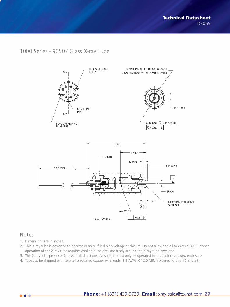
1000 Series - 90507 Glass X-ray Tube
Dimensions are in inches.This X-ray tube is designed to operate in an oil filled high voltage enclosure. Do not allow the oil to exceed 80˚C. Properoperation of the X-ray tube requires cooling oil to circulate freely around the X-ray tube envelope.This X-ray tube produces X-rays in all directions. As such, it must only be operated in a radiation-shielded enclosure.Tubes to be shipped with two teflon-coated copper wire leads, 1 8 AWG X 12.0 MIN, soldered to pins #6 and #2.
1.2.
3.4.
Notes
This publication is the copyright of Oxford Instruments plc and provides outline information only, which (unless agreed by the company in writing) may not be used, applied or reproduced for any purpose or form part of any order or contract or regarded as the representa-tion relating to the products or services concerned. Oxford Instruments’ policy is one of continued improvement. The company reserves the right to alter, without notice the specification, design or conditions of supply of any product or service. Oxford Instruments acknowl-edges all trademarks and registrations. © Oxford Instruments plc, 2015. All rights reserved. Document reference: Part no: DS065 - April 30, 2015
28 Oxford Instruments X-Ray Technology
Glass X-ray Tube1500 Series X-RAYX-RAYGlass X-ray Tube1500 Series
Technical Datasheet
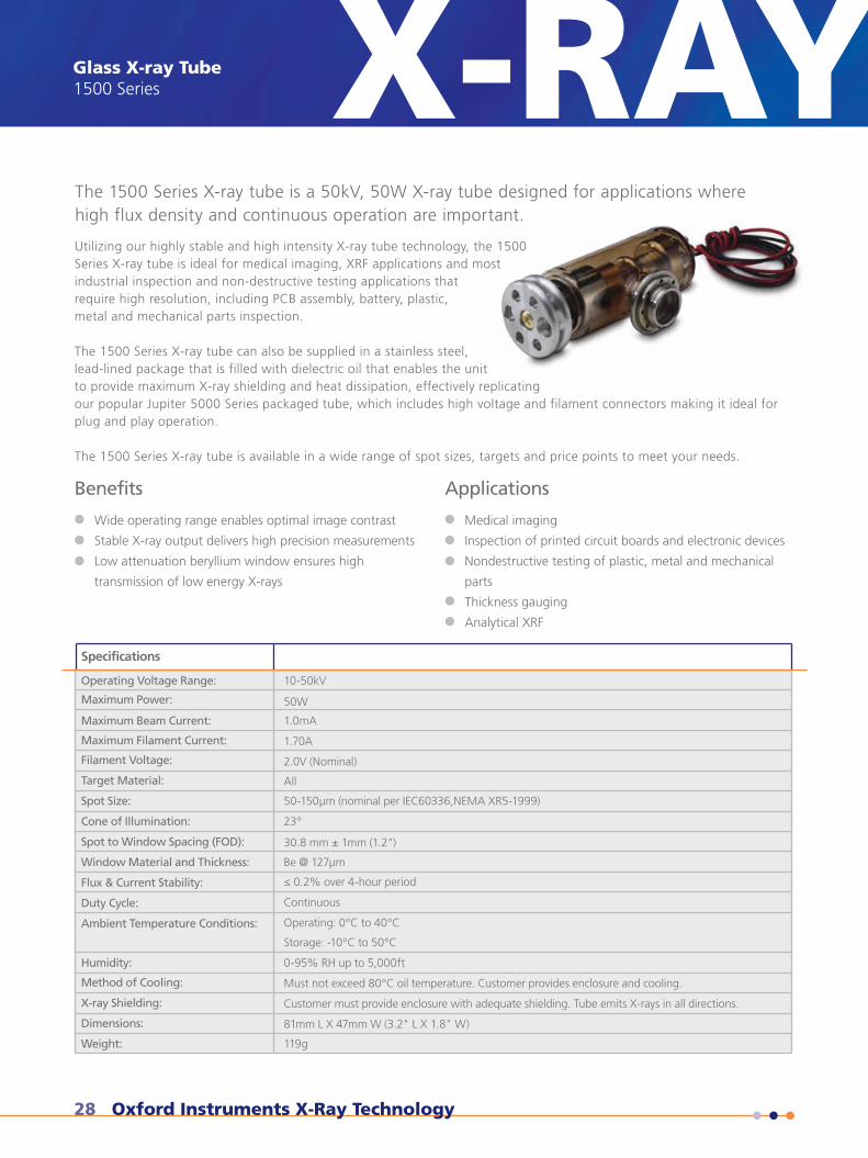
The 1500 Series X-ray tube is a 50kV, 50W X-ray tube designed for applications wherehigh flux density and continuous operation are important.
Utilizing our highly stable and high intensity X-ray tube technology, the 1500Series X-ray tube is ideal for medical imaging, XRF applications and mostindustrial inspection and non-destructive testing applications thatrequire high resolution, including PCB assembly, battery, plastic,metal and mechanical parts inspection.
The 1500 Series X-ray tube can also be supplied in a stainless steel,lead-lined package that is filled with dielectric oil that enables the unitto provide maximum X-ray shielding and heat dissipation, effectively replicatingour popular Jupiter 5000 Series packaged tube, which includes high voltage and filament connectors making it ideal forplug and play operation.
The 1500 Series X-ray tube is available in a wide range of spot sizes, targets and price points to meet your needs.
Benefits
Wide operating range enables optimal image contrast
Stable X-ray output delivers high precision measurements
Low attenuation beryllium window ensures high
transmission of low energy X-rays
Applications
Medical imaging
Inspection of printed circuit boards and electronic devices
Nondestructive testing of plastic, metal and mechanical
parts
Thickness gauging
Analytical XRF
Specifications
Operating Voltage Range:
Maximum Power:
Maximum Beam Current:
Maximum Filament Current:
Filament Voltage:
Target Material:
Spot Size:
Cone of Illumination:
Spot to Window Spacing (FOD):
Window Material and Thickness:
Flux & Current Stability:
Duty Cycle:
Ambient Temperature Conditions:
Humidity:
Method of Cooling:
X-ray Shielding:
Dimensions:
Weight:
10-50kV
50W
1.0mA
1.70A
2.0V (Nominal)
All
50-150µm (nominal per IEC60336,NEMA XR5-1999)
23°
30.8 mm ± 1mm (1.2")
Be @ 127µm
≤ 0.2% over 4-hour period
Continuous
Operating: 0°C to 40°C
Storage: -10°C to 50°C
0-95% RH up to 5,000ft
Must not exceed 80°C oil temperature. Customer provides enclosure and cooling.
Customer must provide enclosure with adequate shielding. Tube emits X-rays in all directions.
81mm L X 47mm W (3.2" L X 1.8" W)
119g
Phone: +1 (831) 439-9729 Email: [email protected] 29
X-RAY Technical DatasheetDS1500
visit www.oxford-instruments.com/xt or [email protected] for more information
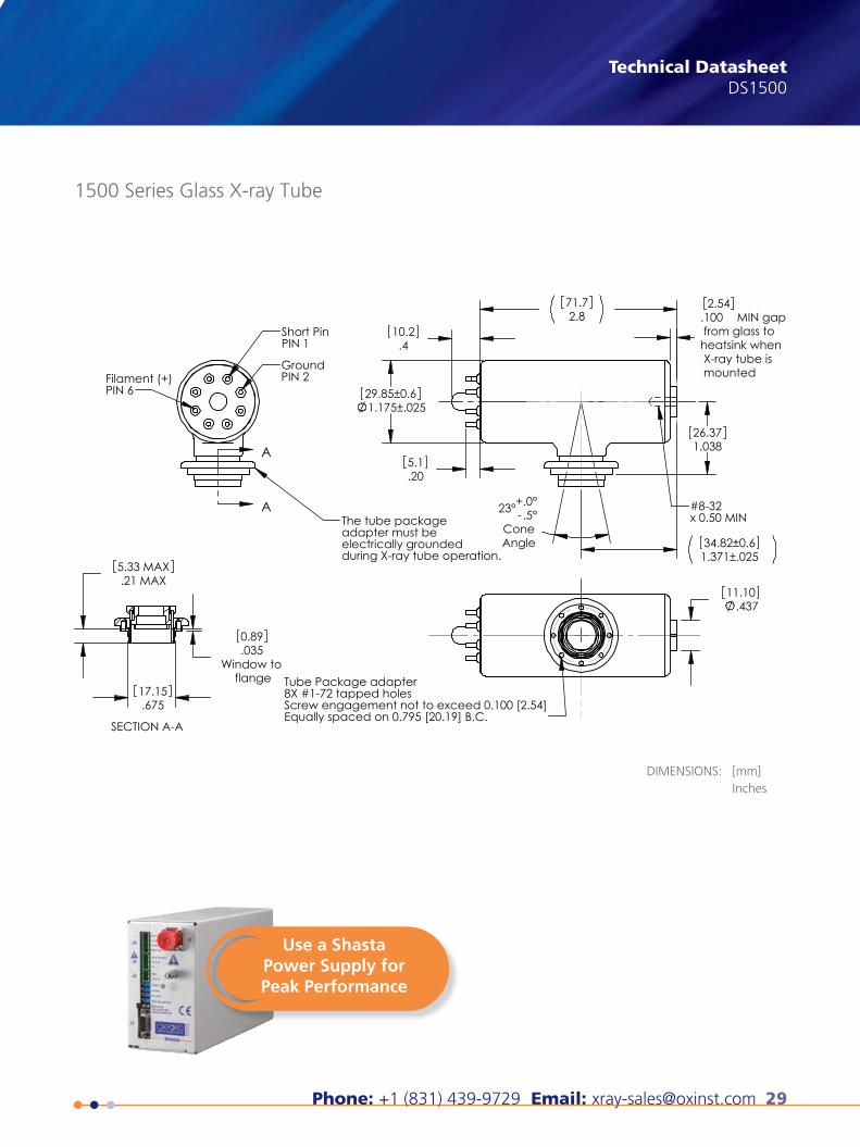
A
A
Short PinPIN 1
Filament (+)PIN 6
GroundPIN 2
The tube packageadapter must be electrically groundedduring X-ray tube operation.
1.03826.37
1.175±.02529.85±0.6
.410.2
.205.1
2.871.7
23° - .5°+.0°
ConeAngle
.100 MIN gap from glass toheatsink when X-ray tube is mounted
2.54
1.371±.02534.82±0.6
#8-32 x 0.50 MIN
.43711.10
Tube Package adapter8X #1-72 tapped holesScrew engagement not to exceed 0.100 [2.54]Equally spaced on 0.795 [20.19] B.C.
.67517.15
.035Window to
flange
0.89
.21 MAX5.33 MAX
SECTION A-A
X-ray Technology360 El Pueblo RoadScotts Valley, CA 95066, USA
Phone: +1 (831) 439-9729Fax: +1 (831) 439-6050Email: [email protected]
THE QUEEN'S AWARDS
FOR ENTERPRISE:
INNOVATION
2012
1500 Series Glass X-ray Tube
DIMENSIONS: [mm]Inches
This publication is the copyright of Oxford Instruments plc and provides outline information only, which (unless agreed by the company in writing) may not be used, applied or reproduced for any purpose or form part of any order or contract or regarded as the representa-tion relating to the products or services concerned. Oxford Instruments’ policy is one of continued improvement. The company reserves the right to alter, without notice the specification, design or conditions of supply of any product or service. Oxford Instruments acknowl-edges all trademarks and registrations. © Oxford Instruments plc, 2015. All rights reserved. Document reference: Part no: DS1500 - February 5, 2015
Use a ShastaPower Supply forPeak Performance
30 Oxford Instruments X-Ray Technology
Glass X-ray Tube1501 Series X-RAYX-RAYGlass X-ray Tube1501 Series
Technical Datasheet
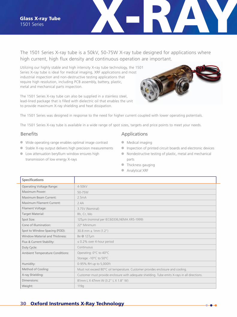
The 1501 Series X-ray tube is a 50kV, 50-75W X-ray tube designed for applications wherehigh current, high flux density and continuous operation are important.
Utilizing our highly stable and high intensity X-ray tube technology, the 1501Series X-ray tube is ideal for medical imaging, XRF applications and mostindustrial inspection and non-destructive testing applications thatrequire high resolution, including PCB assembly, battery, plastic,metal and mechanical parts inspection.
The 1501 Series X-ray tube can also be supplied in a stainless steel,lead-lined package that is filled with dielectric oil that enables the unitto provide maximum X-ray shielding and heat dissipation.
The 1501 Series was designed in response to the need for higher current coupled with lower operating potentials.
The 1501 Series X-ray tube is available in a wide range of spot sizes, targets and price points to meet your needs.
Wide operating range enables optimal image contrast
Stable X-ray output delivers high precision measurements
Low attenuation beryllium window ensures high
transmission of low energy X-rays
ApplicationsBenefits
Medical imaging
Inspection of printed circuit boards and electronic devices
Nondestructive testing of plastic, metal and mechanical
parts
Thickness gauging
Analytical XRF
Specifications
Operating Voltage Range:
Maximum Power:
Maximum Beam Current:
Maximum Filament Current:
Filament Voltage:
Target Material:
Spot Size:
Cone of Illumination:
Spot to Window Spacing (FOD):
Window Material and Thickness:
Flux & Current Stability:
Duty Cycle:
Ambient Temperature Conditions:
Humidity:
Method of Cooling:
X-ray Shielding:
Dimensions:
Weight:
4-50kV
50-75W
2.5mA
2.4A
3.75V (Nominal)
Rh, Cr, Mo
125µm (nominal per IEC60336,NEMA XR5-1999)
22° Minimum
30.8 mm ± 1mm (1.2")
Be @ 127µm
≤ 0.2% over 4-hour period
Continuous
Operating: 0°C to 40°C
Storage: -10°C to 50°C
0-95% RH up to 5,000ft
Must not exceed 80°C oil temperature. Customer provides enclosure and cooling.
Customer must provide enclosure with adequate shielding. Tube emits X-rays in all directions.
81mm L X 47mm W (3.2" L X 1.8" W)
119g
Phone: +1 (831) 439-9729 Email: [email protected] 31
X-RAY Technical DatasheetDS1501
visit www.oxford-instruments.com/xt or [email protected] for more information
X-ray Technology360 El Pueblo RoadScotts Valley, CA 95066, USA
Phone: +1 (831) 439-9729Fax: +1 (831) 439-6050Email: [email protected]
THE QUEEN'S AWARDS
FOR ENTERPRISE:
INNOVATION
2012
1501 Series Glass X-ray Tube
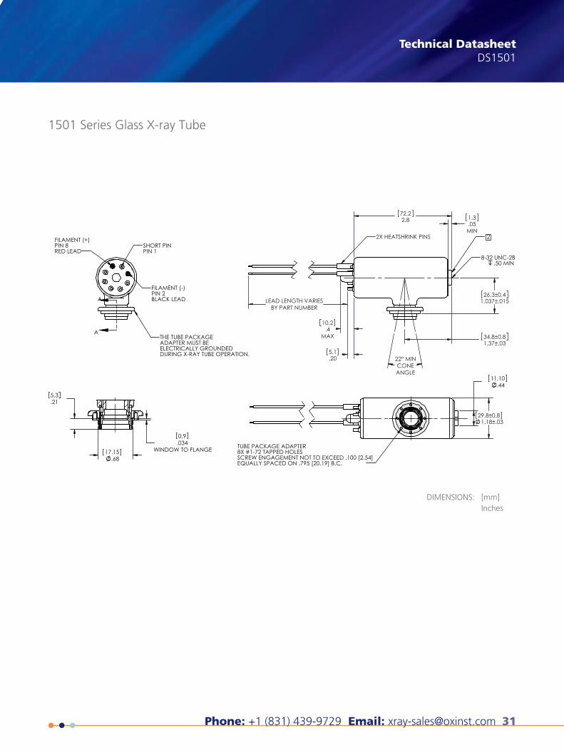
DIMENSIONS: [mm]Inches
A
A
FILAMENT (+)PIN 8RED LEAD
SHORT PINPIN 1
FILAMENT (-)PIN 2BLACK LEAD
THE TUBE PACKAGEADAPTER MUST BE ELECTRICALLY GROUNDEDDURING X-RAY TUBE OPERATION.
.034WINDOW TO FLANGE
0.9
.6817.15
.215.3
LEAD LENGTH VARIESBY PART NUMBER
5.1.20
72.22.8 1.3
.05MIN
10.2.4
MAX
26.3±0.41.037±.015
34.8±0.81.37±.03
22° MINCONEANGLE
2
8-32 UNC-2B .50 MIN
2X HEATSHRINK PINS
.4411.10
29.8±0.81.18±.03
TUBE PACKAGE ADAPTER8X #1-72 TAPPED HOLESSCREW ENGAGEMENT NOT TO EXCEED .100 [2.54]EQUALLY SPACED ON .795 [20.19] B.C.
This publication is the copyright of Oxford Instruments plc and provides outline information only, which (unless agreed by the company in writing) may not be used, applied or reproduced for any purpose or form part of any order or contract or regarded as the representa-tion relating to the products or services concerned. Oxford Instruments’ policy is one of continued improvement. The company reserves the right to alter, without notice the specification, design or conditions of supply of any product or service. Oxford Instruments acknowl-edges all trademarks and registrations. © Oxford Instruments plc, 2014. All rights reserved. Document reference: Part no: DS1501 - August 6, 2014

32 Oxford Instruments X-Ray Technology
Glass X-ray Tube1550 Series X-RAYX-RAYGlass X-ray Tube1550 Series
Technical Datasheet
The 1550 Series X-ray tube is a 50kV, 50W X-ray tube designed for applications wherehigh flux density and continuous operation are important.
Utilizing our highly stable, high intensity X-ray tube technology coupled withgrid-controlled variable focus enables our 1550 Series X-ray tube toproduce very small focal spots; this makes the 1550 Series ideal formost industrial inspection and non-destructive testing applicationsthat require high resolution, including PCB assembly, battery, plastic,metal and mechanical parts inspection. Flexible and reliable, this unitis also highly suited for use with X-ray optics.
The 1550 Series X-ray tube can also be supplied in a stainless steel, lead-lined package that is filled with dielectric oilthat enables the unit to provide maximum X-ray shielding and heat dissipation; this configuration is our popularApogee 5500 Series packaged tube, which includes high voltage and filament connectors making it ideal for plug andplay operation.
Benefits
Wide operating range enables optimal image contrast
Stable X-ray output delivers high precision measurements
Low attenuation beryllium window ensures high
transmission of low energy X-rays
Applications
Medical imaging
Inspection of printed circuit boards and electronic devices
Nondestructive testing of plastic, metal and mechanical
parts
Thickness gauging
Analytical XRF
Specifications
Operating Voltage Range:
Maximum Power:
Maximum Beam Current:
Grid Voltage:
Maximum Filament Current:
Filament Voltage:
Target Material:
Spot Size:
Cone of Illumination:
Spot to Window Spacing (FOD):
Window Material and Thickness:
Flux & Current Stability:
Duty Cycle:
Ambient Temperature Conditions:
Humidity:
Method of Cooling:
X-ray Shielding:
Dimensions:
Weight:
10-50kV
50W
1.0mA
0-100V
1.70A
2.0V (Nominal)
Cu, W, Mo, Co, Rh
<50µm (X and Y)
22°
30.8 mm ± 1mm (1.213")
Be @ 127µm
≤ 0.2% over 4-hour period
Continuous
Operating: 0°C to 40°C
Storage: -10°C to 50°C
0-95% RH up to 5,000ft
Must not exceed 80°C oil temperature. Customer provides enclosure and cooling.
Customer must provide enclosure with adequate shielding. Tube emits X-rays in all directions.
81mm L X 47mm W (3.2" L X 1.8" W)
119g
Phone: +1 (831) 439-9729 Email: [email protected] 33
X-RAY Technical DatasheetDS1550
visit www.oxford-instruments.com/xt or [email protected] for more information
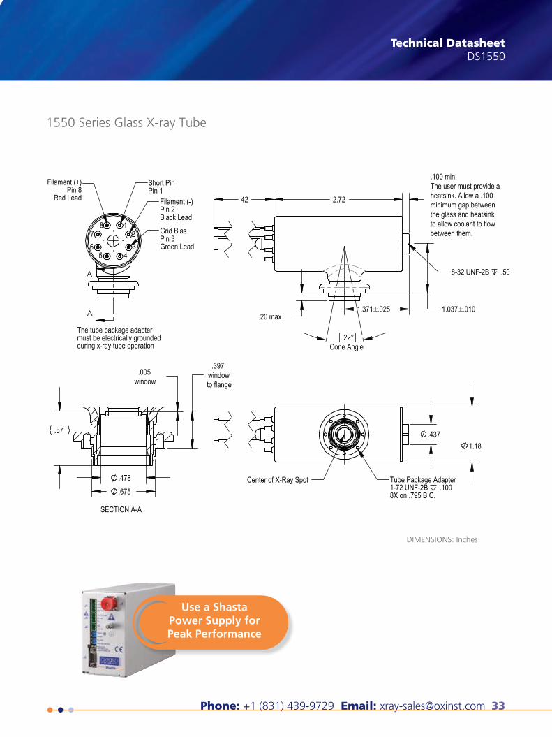
A
A
123
4567
8
Short PinPin 1
Filament (-)Pin 2Black LeadGrid BiasPin 3Green Lead
Filament (+)Pin 8
Red Lead
The tube package adaptermust be electrically groundedduring x-ray tube operation
1.037±.010.20 max
2.72 42
22° Cone Angle
1.371±.025
8-32 UNF-2B .50
.437 1.18
Tube Package Adapter1-72 UNF-2B .1008X on .795 B.C.
Center of X-Ray Spot
.005window
.397window to flange
.57
.675
.478
SECTION A-A
X-ray Technology360 El Pueblo RoadScotts Valley, CA 95066, USA
Phone: +1 (831) 439-9729Fax: +1 (831) 439-6050Email: [email protected]
THE QUEEN'S AWARDS
FOR ENTERPRISE:
INNOVATION
2012
1550 Series Glass X-ray Tube
DIMENSIONS: Inches
This publication is the copyright of Oxford Instruments plc and provides outline information only, which (unless agreed by the company in writing) may not be used, applied or reproduced for any purpose or form part of any order or contract or regarded as the representa-tion relating to the products or services concerned. Oxford Instruments’ policy is one of continued improvement. The company reserves the right to alter, without notice the specification, design or conditions of supply of any product or service. Oxford Instruments acknowl-edges all trademarks and registrations. © Oxford Instruments plc, 2015. All rights reserved. Document reference: Part no: DS1550 - February 5, 2015
.100 minThe user must provide a heatsink. Allow a .100 minimum gap between the glass and heatsink to allow coolant to flow between them.
Use a ShastaPower Supply forPeak Performance
34 Oxford Instruments X-Ray Technology
X-ray Tube Power SupplyShasta Series X-RAYX-RAYX-ray Tube Power SupplyShasta series
Compact Design
Adjustable Emission Current
Voltage & Current Programming
XRF, XRD, Medical Imaging, Industrial Inspection & NDT
Safety Interlock
Bias Voltage Option Available
UL, CE & TUV Certified
Specifications
Operating voltage range:
Maximum Power:
Maximum beam current:
DC Filament Supply:
Voltage Regulation:
Current Regulation:
Ripple:
Stability:
Input Voltage & Power:
Voltage Control:
Interlock:
Protection:
Temperature Conditions:
Temperature Coefficient:
Dimensions:
Weight:
Regulatory & Safety:
Technical Datasheet
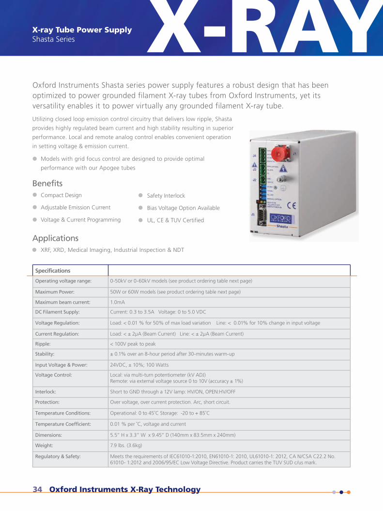
Oxford Instruments Shasta series power supply features a robust design that has beenoptimized to power grounded filament X-ray tubes from Oxford Instruments, yet itsversatility enables it to power virtually any grounded filament X-ray tube.
Utilizing closed loop emission control circuitry that delivers low ripple, Shasta
provides highly regulated beam current and high stability resulting in superior
performance. Local and remote analog control enables convenient operation
in setting voltage & emission current.
0-50kV or 0-60kV models (see product ordering table next page)
50W or 60W models (see product ordering table next page)
1.0mA
Current: 0.3 to 3.5A Voltage: 0 to 5.0 VDC
Load: < 0.01 % for 50% of max load variation Line: < 0.01% for 10% change in input voltage
Load: < ± 2µA (Beam Current) Line: < ± 2µA (Beam Current)
< 100V peak to peak
± 0.1% over an 8-hour period after 30-minutes warm-up
24VDC, ± 10%; 100 Watts
Local: via multi-turn potentiometer (kV ADJ)Remote: via external voltage source 0 to 10V (accuracy ± 1%)
Short to GND through a 12V lamp: HV/ON, OPEN:HV/OFF
Over voltage, over current protection. Arc, short circuit.
Operational: 0 to 45˚C Storage: -20 to + 85˚C
0.01 % per ˚C, voltage and current
5.5” H x 3.3” W x 9.45” D (140mm x 83.5mm x 240mm)
7.9 lbs. (3.6kg)
Meets the requirements of IEC61010-1:2010, EN61010-1: 2010, UL61010-1: 2012, CA N/CSA C22.2 No.61010- 1:2012 and 2006/95/EC Low Voltage Directive. Product carries the TUV SUD c/us mark.
Models with grid focus control are designed to provide optimal
performance with our Apogee tubes
Applications
Benefits
Phone: +1 (831) 439-9729 Email: [email protected] 35
X-RAY Technical DatasheetDS9700001
visit www.oxford-instruments.com/xt or [email protected] for more information
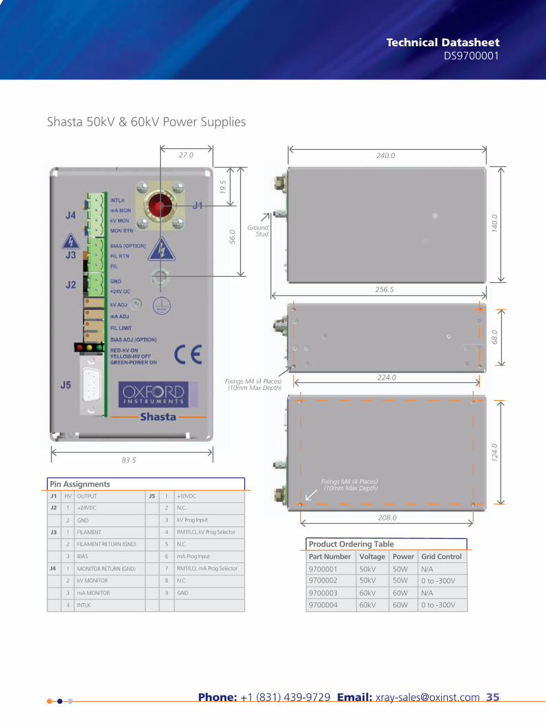
Pin AssignmentsJ1 J5
J2
J3
J4
HV OUTPUT 1
2
3
4
5
6
7
8
9
+10VDC
N.C.
kV Prog Input
RMT/LCL kV Prog Selector
N.C.
mA Prog Input
RMT/LCL mA Prog Selector
N.C.
GND
1 +24VDC
GND
FILAMENT
FILAMENT RETURN (GND)
BIAS
MONITOR RETURN (GND)
kV MONITOR
mA MONITOR
INTLK
2
1
2
3
1
2
3
4
Product Ordering Table
Part Number Voltage Power
9700001
9700002
50kV
50kV
50W
50W
Grid Control
9700003
9700004
60kV
60kV
60W
60W
N/A
0 to -300V
N/A
0 to -300V
X-ray Technology360 El Pueblo RoadScotts Valley, CA 95066, USA
Phone: +1 (831) 439-9729Fax: +1 (831) 439-6050Email: [email protected]
THE QUEEN'S AWARDS
FOR ENTERPRISE:
INNOVATION
2012
Shasta 50kV & 60kV Power Supplies
56.0
19.5
27.0
83.5
Ground Stud
240.0
256.5
140.
068
.0
224.0
208.0
124.
0
Fixings M4 (4 Places) (10mm Max Depth)
Fixings M4 (4 Places) (10mm Max Depth)
This publication is the copyright of Oxford Instruments plc and provides outline information only, which (unless agreed by the company in writing) may not be used, applied or reproduced for any purpose or form part of any order or contract or regarded as the representa-tion relating to the products or services concerned. Oxford Instruments’ policy is one of continued improvement. The company reserves the right to alter, without notice the specification, design or conditions of supply of any product or service. Oxford Instruments acknowl-edges all trademarks and registrations. © Oxford Instruments plc, 2015. All rights reserved. Document reference: Part no: DS9700001 - June 22, 2015
36 Oxford Instruments X-Ray Technology
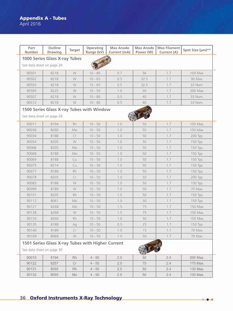
Appendix A - TubesApril 2016
Part Number
Outline Drawing
TargetOperating Range (kV)
Max Anode Current (mA)
Max Anode Power (W)
Max Filament Current (A)
Spot Size (μm)**
1000 Series Glass X-ray Tubes
See data sheet on page 26
90501 8218 W 10 - 80 0.7 56 1.7 100 Max.
90502 8218 W 10 - 65 0.5 32.5 1.7 90 Max.
90503 8218 W 10 - 65 0.5 32.5 1.7 33 Nom.
90505 8225 W 10 - 50 1.0 50 1.7 200 Max.
90507 8218 W 10 - 80 0.5 40 1.7 33 Nom.
90512 8218 W 10 - 80 0.5 40 1.7 33 Nom.
1500 Series Glass X-ray Tubes with Window
See data sheet on page 28
90011 8194 Rh 10 - 50 1.0 50 1.7 150 Max.
90030 8260 Mo 10 - 50 1.0 50 1.7 150 Max.
90034 8188 Cr 10 - 50 1.0 50 1.7 200 Typ.
90054 8205 W 10 - 50 1.0 50 1.7 150 Typ.
90066 8205 Mo 10 - 50 1.0 50 1.7 150 Typ.
90068 8188 Mo 10 - 50 1.0 50 1.7 150 Typ.
90069 8188 Cu 10 - 50 1.0 50 1.7 150 Typ.
90075 8214 Cu 10 - 30 1.0 50 1.7 150 Typ.
90077 8188 Rh 10 - 50 1.0 50 1.7 150 Typ.
90078 8205 Cr 10 - 50 1.0 50 1.7 200 Typ.
90083 8188 W 10 - 50 1.0 50 1.7 150 Typ.
90099 8189 W 10 - 50 1.0 50 1.7 70 Max.
90101 8205 Rh 10 - 50 1.0 50 1.7 150 Typ.
90112 8061 Mo 10 - 50 1.0 50 1.7 150 Typ.
90127 8268 Mo 10 - 50 1.5 75 1.7 150 Max.
90128 8268 W 10 - 50 1.5 75 1.7 150 Max.
90133 8260 Rh 10 - 50 1.0 50 1.7 150 Max.
90135 8188 Ag 10 - 50 0.5 25 1.7 150 Typ.
90140 8189 Cr 10 - 50 1.0 15 1.7 70 Max.
90169 8069 W 10 - 50 1.0 50 1.7 70 Max.
1501 Series Glass X-ray Tubes with Higher Current
See data sheet on page 30
90015 8194 Rh 4 - 50 2.5 50 2.4 200 Max. 90122 8257 Cr 4 - 50 2.0 75 2.4 175 Max. 90131 8055 Rh 4 - 50 2.5 50 2.4 130 Max. 90132 8055 Mo 4 - 50 2.5 50 2.4 130 Max.
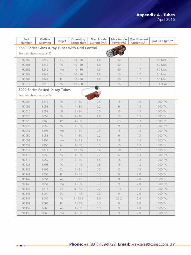
Phone: +1 (831) 439-9729 Email: [email protected] 37
Appendix A - TubesApril 2016
Part Number
Outline Drawing
TargetOperating Range (kV)
Max Anode Current (mA)
Max Anode Power (W)
Max Filament Current (A)
Spot Size (μm)**
1550 Series Glass X-ray Tubes with Grid Control
See data sheet on page 32
90200 8242 Cu 10 - 50 1.0 50 1.7 50 Max.
90201 8242 W 10 - 50 1.0 50 1.7 50 Max.
90202 8242 Mo 10 - 50 1.0 50 1.7 50 Max.
90203 8242 Co 10 - 50 1.0 10 1.7 50 Max.
90204 8242 Rh 10 - 50 1.0 50 1.7 50 Max.
90512 8218 W 10 - 80 0.7 56 1.7 33 Nom.
3000 Series Potted X-ray Tubes
See data sheet on page 24
90004 8145 W 4 - 30 0.5 15 1.3 1000 Typ.
90006 8053 W 4 - 30 0.2 6 1.3 1000 Typ.
90020 8052 Ti 4 - 30 0.5 15 1.3 1000 Typ.
90025 8052 W 4 - 10 1.0 10 1.3 1000 Typ.
90026 8263 Pd 4 - 30 0.1 2.5 1.3 1000 Typ.
90036 8053 W 4 - 30 0.3 9 1.3 1000 Typ.
90042 8195 Mo 4 - 30 0.5 15 1.3 1000 Typ.
90050 8053 W 4 - 30 0.2 6 1.3 1000 Typ.
90053 8204 Mo 4 - 15 1.0 15 1.3 1000 Typ.
90057 8156 Au 4 - 30 0.5 15 1.3 1000 Typ.
90072 8211 Cu 10 - 25 0.4 10 1.7 1000 Typ.
90116 8053 W 4 - 30 0.2 6 1.3 1000 Typ.
90118 8052 Fe 4 - 10 1.5 15 1.3 1000 Typ.
90125 8195 W 4 - 40 0.5 15 1.3 1000 Typ.
90136 8195 Cu 4 - 30 0.5 12 1.3 1000 Typ.
90141 8054 Rh 4 - 40 0.3 9 2.0 1000 Typ.
90142 8054 Ag 5 - 40 0.3 9 2.0 1000 Typ.
90143 8054 Mo 4 - 30 0.3 9 2.0 1000 Typ.
90144 8214 Cr 4 - 7.5 0.2 1.5 1.3 1000 Typ.
90145 8054 Pd 4 - 40 0.3 9 2.0 1000 Typ.
90146 8057 W 5 - 13.6 2.0 27.2 2.0 1000 Typ.
90151 8063 Rh 4 - 30 0.3 9 2.0 1000 Typ.
90152 8063 Ag 4 - 30 0.3 9 2.0 1000 Typ.
90153 8063 Mo 4 - 30 0.3 9 2.0 1000 Typ.
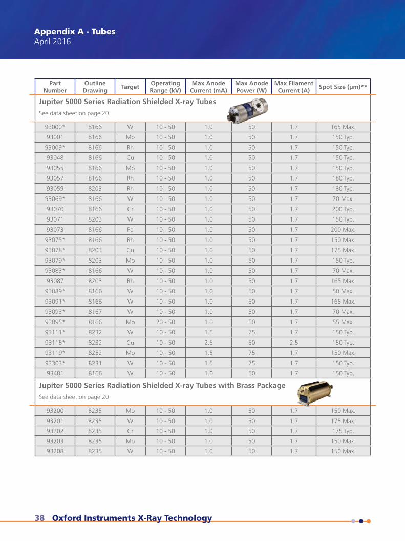
38 Oxford Instruments X-Ray Technology
Appendix A - TubesApril 2016
Part Number
Outline Drawing
TargetOperating Range (kV)
Max Anode Current (mA)
Max Anode Power (W)
Max Filament Current (A)
Spot Size (μm)**
Jupiter 5000 Series Radiation Shielded X-ray Tubes See data sheet on page 20
93000* 8166 W 10 - 50 1.0 50 1.7 165 Max.
93001 8166 Mo 10 - 50 1.0 50 1.7 150 Typ.
93009* 8166 Rh 10 - 50 1.0 50 1.7 150 Typ.
93048 8166 Cu 10 - 50 1.0 50 1.7 150 Typ.
93055 8166 Mo 10 - 50 1.0 50 1.7 150 Typ.
93057 8166 Rh 10 - 50 1.0 50 1.7 180 Typ.
93059 8203 Rh 10 - 50 1.0 50 1.7 180 Typ.
93069* 8166 W 10 - 50 1.0 50 1.7 70 Max.
93070 8166 Cr 10 - 50 1.0 50 1.7 200 Typ.
93071 8203 W 10 - 50 1.0 50 1.7 150 Typ.
93073 8166 Pd 10 - 50 1.0 50 1.7 200 Max.
93075* 8166 Rh 10 - 50 1.0 50 1.7 150 Max.
93078* 8203 Cu 10 - 50 1.0 50 1.7 175 Max.
93079* 8203 Mo 10 - 50 1.0 50 1.7 150 Typ.
93083* 8166 W 10 - 50 1.0 50 1.7 70 Max.
93087 8203 Rh 10 - 50 1.0 50 1.7 165 Max.
93089* 8166 W 10 - 50 1.0 50 1.7 50 Max.
93091* 8166 W 10 - 50 1.0 50 1.7 165 Max.
93093* 8167 W 10 - 50 1.0 50 1.7 70 Max.
93095* 8166 Mo 20 - 50 1.0 50 1.7 55 Max.
93111* 8232 W 10 - 50 1.5 75 1.7 150 Typ.
93115* 8232 Cu 10 - 50 2.5 50 2.5 150 Typ.
93119* 8252 Mo 10 - 50 1.5 75 1.7 150 Max.
93303* 8231 W 10 - 50 1.5 75 1.7 150 Typ.
93401 8166 W 10 - 50 1.0 50 1.7 150 Typ.
Jupiter 5000 Series Radiation Shielded X-ray Tubes with Brass Package See data sheet on page 20
93200 8235 Mo 10 - 50 1.0 50 1.7 150 Max.
93201 8235 W 10 - 50 1.0 50 1.7 175 Max.
93202 8235 Cr 10 - 50 1.0 50 1.7 175 Typ.
93203 8235 Mo 10 - 50 1.0 50 1.7 150 Max.
93208 8235 W 10 - 50 1.0 50 1.7 150 Max.
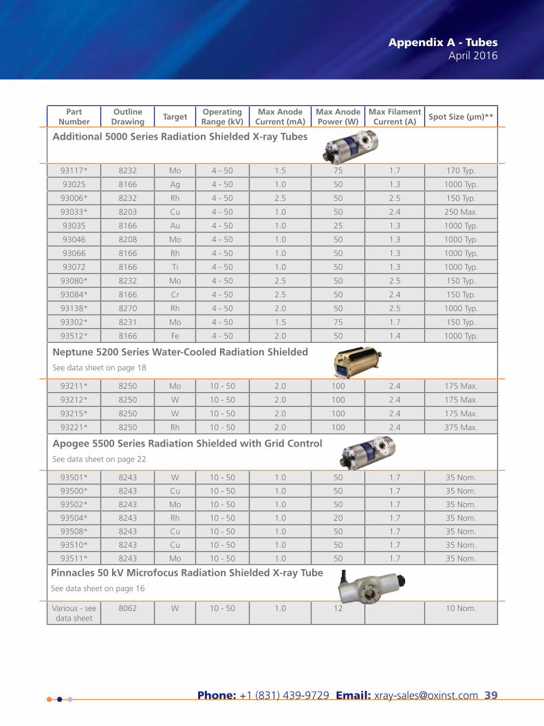
Phone: +1 (831) 439-9729 Email: [email protected] 39
Appendix A - TubesApril 2016
Part Number
Outline Drawing
TargetOperating Range (kV)
Max Anode Current (mA)
Max Anode Power (W)
Max Filament Current (A)
Spot Size (μm)**
Additional 5000 Series Radiation Shielded X-ray Tubes
93117* 8232 Mo 4 - 50 1.5 75 1.7 170 Typ.
93025 8166 Ag 4 - 50 1.0 50 1.3 1000 Typ.
93006* 8232 Rh 4 - 50 2.5 50 2.5 150 Typ.
93033* 8203 Cu 4 - 50 1.0 50 2.4 250 Max.
93035 8166 Au 4 - 50 1.0 25 1.3 1000 Typ.
93046 8208 Mo 4 - 50 1.0 50 1.3 1000 Typ.
93066 8166 Rh 4 - 50 1.0 50 1.3 1000 Typ.
93072 8166 Ti 4 - 50 1.0 50 1.3 1000 Typ.
93080* 8232 Mo 4 - 50 2.5 50 2.5 150 Typ.
93084* 8166 Cr 4 - 50 2.5 50 2.4 150 Typ.
93138* 8270 Rh 4 - 50 2.0 50 2.5 1000 Typ.
93302* 8231 Mo 4 - 50 1.5 75 1.7 150 Typ.
93512* 8166 Fe 4 - 50 2.0 50 1.4 1000 Typ.
Neptune 5200 Series Water-Cooled Radiation Shielded
See data sheet on page 18
93211* 8250 Mo 10 - 50 2.0 100 2.4 175 Max.
93212* 8250 W 10 - 50 2.0 100 2.4 175 Max.
93215* 8250 W 10 - 50 2.0 100 2.4 175 Max.
93221* 8250 Rh 10 - 50 2.0 100 2.4 375 Max.
Apogee 5500 Series Radiation Shielded with Grid Control
See data sheet on page 22
93501* 8243 W 10 - 50 1.0 50 1.7 35 Nom.
93500* 8243 Cu 10 - 50 1.0 50 1.7 35 Nom.
93502* 8243 Mo 10 - 50 1.0 50 1.7 35 Nom.
93504* 8243 Rh 10 - 50 1.0 20 1.7 35 Nom.
93508* 8243 Cu 10 - 50 1.0 50 1.7 35 Nom.
93510* 8243 Cu 10 - 50 1.0 50 1.7 35 Nom.
93511* 8243 Mo 10 - 50 1.0 50 1.7 35 Nom.
Pinnacles 50 kV Microfocus Radiation Shielded X-ray Tube
See data sheet on page 16
Various - see data sheet
8062 W 10 - 50 1.0 12 10 Nom.
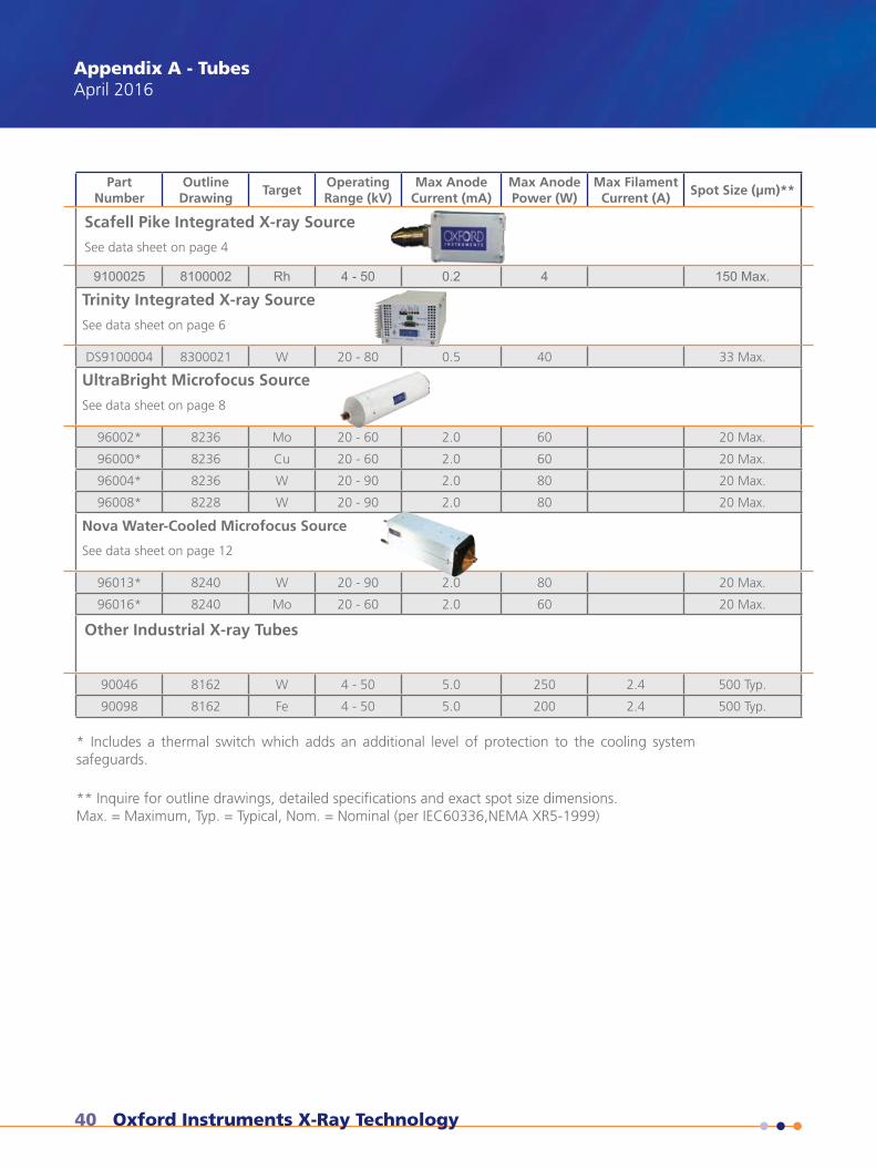
40 Oxford Instruments X-Ray Technology
Appendix A - TubesApril 2016
Part Number
Outline Drawing
TargetOperating Range (kV)
Max Anode Current (mA)
Max Anode Power (W)
Max Filament Current (A)
Spot Size (μm)**
Scafell Pike Integrated X-ray Source
See data sheet on page 4
9100025 8100002 Rh 4 - 50 0.2 4 150 Max.
Trinity Integrated X-ray Source
See data sheet on page 6
DS9100004 8300021 W 20 - 80 0.5 40 33 Max.
UltraBright Microfocus Source
See data sheet on page 8
96002* 8236 Mo 20 - 60 2.0 60 20 Max.
96000* 8236 Cu 20 - 60 2.0 60 20 Max.
96004* 8236 W 20 - 90 2.0 80 20 Max.
96008* 8228 W 20 - 90 2.0 80 20 Max.
Nova Water-Cooled Microfocus Source
See data sheet on page 12
96013* 8240 W 20 - 90 2.0 80 20 Max.
96016* 8240 Mo 20 - 60 2.0 60 20 Max.
Other Industrial X-ray Tubes
90046 8162 W 4 - 50 5.0 250 2.4 500 Typ.
90098 8162 Fe 4 - 50 5.0 200 2.4 500 Typ.
* Includes a thermal switch which adds an additional level of protection to the cooling system safeguards.
** Inquire for outline drawings, detailed specifications and exact spot size dimensions. Max. = Maximum, Typ. = Typical, Nom. = Nominal (per IEC60336,NEMA XR5-1999)
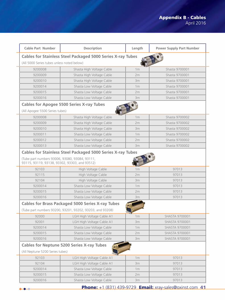
Phone: +1 (831) 439-9729 Email: [email protected] 41
Appendix B - CablesApril 2016
Cable Part Number Description Length Power Supply Part Number
Cables for Stainless Steel Packaged 5000 Series X-ray Tubes
(All 5000 Series tubes unless noted below)
9200008 Shasta High Voltage Cable 1m Shasta 9700001
9200009 Shasta High Voltage Cable 2m Shasta 9700001
9200010 Shasta High Voltage Cable 3m Shasta 9700001
9200014 Shasta Low Voltage Cable 1m Shasta 9700001
9200015 Shasta Low Voltage Cable 2m Shasta 9700001
9200016 Shasta Low Voltage Cable 3m Shasta 9700001
Cables for Apogee 5500 Series X-ray Tubes
(All Apogee 5500 Series tubes)
9200008 Shasta High Voltage Cable 1m Shasta 9700002
9200009 Shasta High Voltage Cable 2m Shasta 9700002
9200010 Shasta High Voltage Cable 3m Shasta 9700002
9200011 Shasta Low Voltage Cable 1m Shasta 9700002
9200012 Shasta Low Voltage Cable 2m Shasta 9700002
9200013 Shasta Low Voltage Cable 3m Shasta 9700002
Cables for Stainless Steel Packaged 5000 Series X-ray Tubes
(Tube part numbers 93006, 93080, 93084, 93111,93115, 93119, 93138, 93302, 93303, and 93512)
92103 High Voltage Cable 1m 97013
92115 High Voltage Cable 2m 97013
92104 High Voltage Cable 3m 97013
9200014 Shasta Low Voltage Cable 1m 97013
9200015 Shasta Low Voltage Cable 2m 97013
9200016 Shasta Low Voltage Cable 3m 97013
Cables for Brass Packaged 5000 Series X-ray Tubes
(Tube part numbers 93200, 93201, 93202, 93203, and 93208)
92000 LGH High Voltage Cable A1 1m SHASTA 9700001
92001 LGH High Voltage Cable A1 3m SHASTA 9700001
9200014 Shasta Low Voltage Cable 1m SHASTA 9700001
9200015 Shasta Low Voltage Cable 2m SHASTA 9700001
9200016 Shasta Low Voltage Cable 3m SHASTA 9700001
Cables for Neptune 5200 Series X-ray Tubes
(All Neptune 5200 Series tubes)
92103 LGH High Voltage Cable A1 1m 97013
92104 LGH High Voltage Cable A1 3m 97013
9200014 Shasta Low Voltage Cable 1m 97013
9200015 Shasta Low Voltage Cable 2m 97013
9200016 Shasta Low Voltage Cable 3m 97013
42 Oxford Instruments X-Ray Technology
ApplicationFor X-ray tubes that have been in storage or inactive for a period of three months or more.
DescriptionAfter a period of not being used, typically three months or more, residual gasses are released from the internal surfaces of the X-ray tube and accumulate into the tube vacuum. If the maximum rated voltage (in kV) is applied after a period of storage without performing a conditioning procedure, permanent damage to the X-ray tube may occur due to the destructive nature of high voltage arcs in the ionized gas. The following conditioning procedure is appropriate for both “new tubes”, as there may have been a period of storage, as well as tubes that have been stored for three months or more.
ProcedureTo prevent this damage the following special conditioning process should be followed:
• Adjust the kV to the lowest kV that your specific tube is rated for. Set the beam current to 0 mA and if any instability is noted on the mA meter allow it to stabilize to display 0mA. Operate at this condition for a minimum of 15 minutes.
• While maintaining the kV set in the previous step, adjust the beam current to 20% of rated maximum. Maintain this setting for 5 minutes or longer, until no instability is noted on the mA meter.
• Increase high voltage in 5kV steps at 5 minute intervals until 50% of maximum rated kV is reached. Hold 5 minutes at these conditions.
• Increase beam current to maximum rated mA.
• Continue to increase high voltage as before, in 5kV steps every 5 minutes until maximum rated kV or your maximum operat-ing kV is reached. Allow at least 5 minutes at full power to insure that the tube is operating correctly in your system.
NoteIf instability (especially loud popping) is observed, lower the kV setting to the previous step. Allow mA to stabilize for at least 5 minutes before increasing settings again.
X-ray Tube Conditioning Procedure Application Note
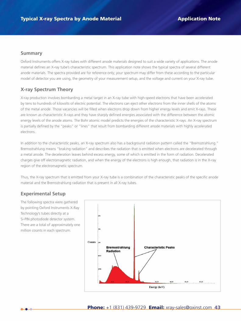
Phone: +1 (831) 439-9729 Email: [email protected] 43
Typical X-ray Spectra by Anode Material
Summary
Oxford Instruments offers X-ray tubes with different anode materials designed to suit a wide variety of applications. The anode
material defines an X-ray tube’s characteristic spectrum. This application note shows the typical spectra of several different
anode materials. The spectra provided are for reference only; your spectrum may differ from these according to the particular
model of detector you are using, the geometry of your measurement setup, and the voltage and current on your X-ray tube.
X-ray Spectrum Theory
X-ray production involves bombarding a metal target in an X-ray tube with high-speed electrons that have been accelerated
by tens to hundreds of kilovolts of electric potential. The electrons can eject other electrons from the inner shells of the atoms
of the metal anode. Those vacancies will be filled when electrons drop down from higher energy levels and emit X-rays. These
are known as characteristic X-rays and they have sharply defined energies associated with the difference between the atomic
energy levels of the anode atoms. The Bohr atomic model predicts the energies of the characteristic X-rays. An X-ray spectrum
is partially defined by the “peaks” or “lines” that result from bombarding different anode materials with highly accelerated
electrons.
In addition to the characteristic peaks, an X-ray spectrum also has a background radiation pattern called the “Bremsstrahlung.”
Bremsstrahlung means “braking radiation” and describes the radiation that is emitted when electrons are decelerated through
a metal anode. The deceleration leaves behind excess energy, some of which is emitted in the form of radiation. Decelerated
charges give off electromagnetic radiation, and when the energy of the electrons is high enough, that radiation is in the X-ray
region of the electromagnetic spectrum.
Thus, the X-ray spectrum that is emitted from your X-ray tube is a combination of the characteristic peaks of the specific anode
material and the Bremsstrahlung radiation that is present in all X-ray tubes.
Experimental Setup
The following spectra were gathered
by pointing Oxford Instruments X-Ray
Technology’s tubes directly at a
Si-PIN photodiode detector system.
There are a total of approximately one
million counts in each spectrum.
Application Note
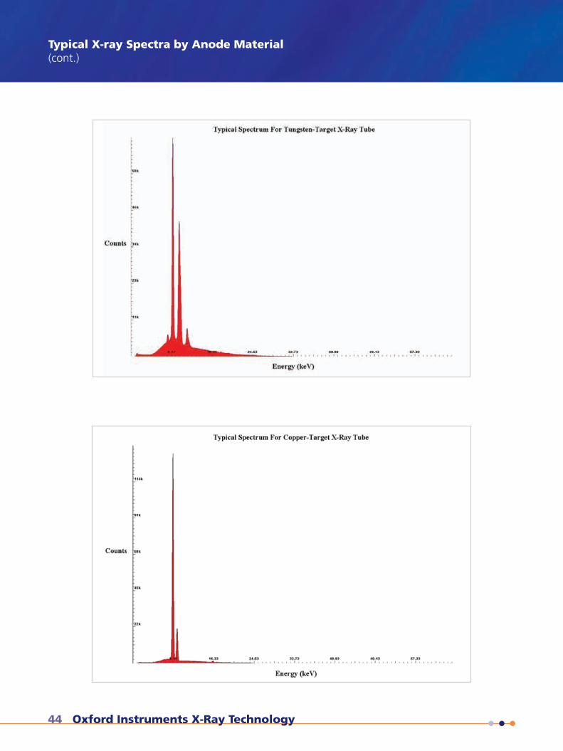
44 Oxford Instruments X-Ray Technology
Typical X-ray Spectra by Anode Material(cont.)
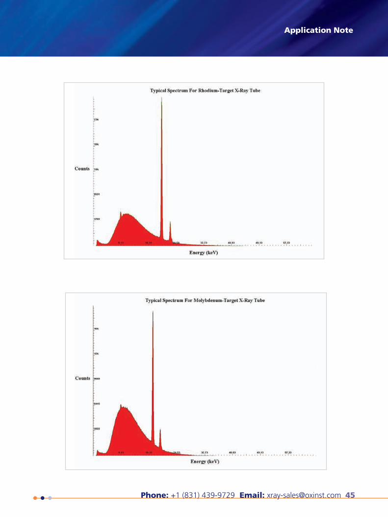
46 Oxford Instruments X-Ray Technology
How to determine the operational range of your X-ray tube
Summary
An X-ray tube is constrained in its operating range by four factors – maximum filament current, maximum power delivered to
the anode, and maximum and minimum anode voltage. By operating your X-ray tube within these parameters, you may be able
to achieve better results for your specific application while ensuring maximum longevity of your X-ray tube. This application note
clarifies the constraints above and shows how an operating range is constructed. You can find all the particular values for your
X-ray tube described in this application note on the datasheet.
Maximum Filament Current
The maximum filament current is a very strict constraint that prevents the filament from burning out, just like the filament in an
incandescent light bulb. Like any other wire, a filament will melt because it cannot dissipate the heat generated from excessive
current. Oxford Instruments X-Ray Technology has conducted extensive testing to determine the maximum current the filament
in your X-ray tube can withstand. A common value is 1.7A, but this value varies by filament type and is given on the datasheet
that comes with your X-ray tube. It constrains the first part of the operating range before the maximum power requirement
takes over.
Maximum Power
Like the filament current limit, the power limit is a strict constraint that prevents the target from sublimating. An X-ray tube
accelerates a very narrow beam of electrons to the target with a total power P = IV, where I is the beam current (not to be
confused with the filament current – the current delivered to the filament itself) and V is the anode voltage. As you can see, this
total power limit does not necessarily prevent using a higher beam current or voltage at a given power. Because beam current
and voltage are inversely proportional in this relationship, raising one and lowering the other may still allow you to operate the
X-ray tube within the maximum power constraint. Keep in mind that the anode voltage is limited as well, as detailed below. The
maximum power constraint takes over after the filament limit is no longer a factor in the operating range.
Minimum and Maximum Anode Voltage
An X-ray tube requires a minimum high voltage applied to the anode in order to draw off electrons from the filament. When
this condition is satisfied, the beam of electrons will form and accelerate towards the target. Below the minimum anode voltage,
electrons will not be drawn off the filament, and thus the tube will produce no X-rays. At voltages lower than the minimum,
some power supplies will overdrive (and potentially melt) the filament in an attempt to produce beam current when there are
no electrons available. Our Shasta power supplies are designed to prevent damage to the filament. It is extremely important that
you do not attempt to obtain beam current below this minimum anode voltage to avoid damaging the filament. On the other
hand, the X-ray tube can only stand off a maximum high voltage applied to the anode. Beyond this voltage, arcing will occur
and this can severely damage your X-ray tube. Both the minimum and maximum high voltages are sharp cut-offs that form the
left and right edges of the operating range.
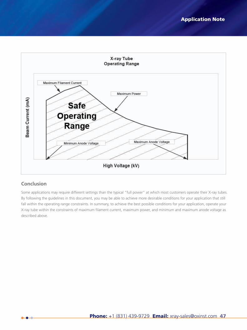
Phone: +1 (831) 439-9729 Email: [email protected] 47
Application Note
Conclusion
Some applications may require different settings than the typical “full power” at which most customers operate their X-ray tubes.
By following the guidelines in this document, you may be able to achieve more desirable conditions for your application that still
fall within the operating range constraints. In summary, to achieve the best possible conditions for your application, operate your
X-ray tube within the constraints of maximum filament current, maximum power, and minimum and maximum anode voltage as
described above.
48 Oxford Instruments X-Ray Technology
When purchasing an X-ray tube, one of the most important questions which must to be answered is: how will the tube be
packaged? System designers often put a lot of thought into the tube specifications, such as target material, spot size, etc, but
the physical packaging of the tube can be a critical design choice. Many factors, including heat dissipation, radiation shielding,
and design time must be considered.
Bare Tube
Bare tubes are just that – X-ray tubes with nothing else. It is incumbent on the system designer to design the radiation shielding,
the insulating material, the high voltage and filament connections, and power supply integration. This can be quite a complex
task, and is generally only appropriate for very large volume systems with specific requirements that cannot be met with Oxford’s
proven tube packaging solutions.
Potted Tube
Potted tubes are encapsulated in a silicone rubber material to provide electrical isolation and, in some cases, radiation shielding.
High and low voltage cables may be included in the potting to aid connection to the X-ray power supply. Potted tubes provide
an easier integration option than bare X-ray tubes however heat dissipation in a potted tube can be a challenge, and so potted
tubes tend to be appropriate in low power or low duty cycle applications.
Packaged Tube
Packaged tubes are enclosed in a metal housing which acts as both a radiation shield and a cooling vessel. The packages are
filled with a high dielectric liquid which both prevents high voltage breakdown (arcing) and effective cooling, requiring only an
external fan to provide 50W of continuous power in many applications. Higher power packages with integrated water cooling
systems are also available. Oxford’s packaged tubes are fitted with connectors for easy plug-and-play operation with our Shasta
X-ray power supply, enabling a quick setup procedure.
Integrated Source
Integrated X-ray sources include an X-ray tube, a high voltage and a low voltage power supply, and an analog or digital
interface conveniently packaged in one box. This frees the system designer from all high voltage design concerns, and allows the
X-ray device to be treated as a true “black box” component. Integrated solutions also speed up time-to-market, as the system
designer only needs to integrate with a simple analog or digital interface, and won’t be bogged down with often mysterious
high voltage integration problems.
Selecting Your X-ray Tube Packaging Application Note
Phone: +1 (831) 439-9729 Email: [email protected] 49
Many Oxford Instruments X-ray tubes come equipped with beryllium X-ray windows for maximum flux transmission. Beryllium is a metal that has low density and low atomic mass, and hence very low absorption of X-rays, making beryllium the preferred choice for X-ray tube windows where low energy transmission is desired.
Oxford Instruments also produces glass window tubes, which are much more robust than their beryllium counterparts, with the trade-off of decreased low energy flux. Glass window tubes are suitable for a wide variety of applications, including imaging and some types of analysis, and should be considered in harsh, humid, or debris filled environments.
If your X-ray tube has a beryllium window, please keep the following considerations in mind:
• The beryllium exit window is comprised of high purity vacuum tight beryllium metal, typically 127 microns thick.
• Beryllium can be toxic if improperly handled. Avoid contact with the beryllium window.
• The beryllium window is fragile and will be damaged by the slightest impact.
• Beryllium is highly soluble in polar solvents. Examples of polar solvents include water (including humidity), alcohol and acids. It is essential that you do not expose the beryllium window to these agents for prolonged periods of time, as they will destroy the beryllium window and compromise the internal high vacuum of the X-ray tube, causing it to fail.
• Unless absolutely necessary, all care should be taken to avoid any contact with the beryllium window, and tube installation should take into consideration keeping the window free of dust and debris. Should your beryllium exit window need to be cleaned, gently use a cotton swab and acetone (a non-polar solvent) and then immediately dry thoroughly with a cotton swab or soft dry air. Please note that damage to the beryllium window due to mishandling is not covered under your warranty.
• Helium is often used in X-ray spectroscopy. Helium is a very small atom and has a high transmission rate through the beryllium window. At a minimum, only beryllium exit windows of at least 127 microns should be considered when operating an X-ray tube in the presence of a Helium environment.
• If you operate an X-ray tube with a beryllium window in a vacuum environment, it is important to remember that the beryl-lium window is brittle and susceptible to damage caused by cycling between atmospheric pressure and vacuum environments typical for analytical analysis. Utilization of a secondary chamber is recommended to allow the X-ray tube to operate at sub-atmospheric pressures without cycling for each sample introduction.
Application NoteCaring for the Beryllium Window of an X-ray Tube
50 Oxford Instruments X-Ray Technology
The process of producing electrons necessary for the production of X-rays in an X-ray tube begins by heating a tungsten wire.
When heated to approximately 2000 degrees Celsius, tungsten is a copious emitter of electrons.
From this point several trade-offs in design become factors, which must be considered. The resulting design of a modern X-ray
tube seeks to balance the relationship between performance and filament longevity.
Of importance to those users seeking a small X-ray focal spot, the relationship between a smaller wire filament and a small focal
spot is well established. (This applies only to small focal spots when utilizing a tungsten wire filament. In the case of microfocus
X-ray tubes, a dispenser cathode is typically employed.)
Since a smaller filament is preferred where possible, a typical filament “driver” circuit must be able to control the current to
the filament quite carefully. This is due to the important relationship between filament current and actual temperature of the
filament wire itself.
By example, the Jupiter Series 5000 X-ray tube requires more than 1.5 Amps current at 2 Volts to achieve the required filament
temperature necessary for electron emission. However above 1.7 amps the filament enters a very high region of evaporation,
and by 1.75 amps the filament reaches its melting point. Therefore careful control of the filament circuit is essential to a long
lived X-ray tube. Our Shasta X-ray tube power supply has a tightly designed circuit which prevents the filament from exceeding
its maximum allowable current. The Shasta power supply is perfectly matched to our X-ray tubes.
The process of heating the helical tungsten filament to produce electrons naturally causes the filament to evaporate. After a
certain number of hours of normal operation, the filament will thin to the point of failure. The rate of filament evaporation,
and thus the total number of hours required to thin the filament to the point of failure is a function of the chosen operating
conditions.
The filament current required to heat and achieve a given X-ray beam current differs depending upon the required applied high
voltage, as shown in Figure 1. To determine the anticipated life of a helical tungsten filament, one must estimate the average
filament current employed throughout its life. Once estimated, the rate of evaporation can be used to estimate the normal
filament life as shown in Figure 2. For example, if the user normally operates the X-ray tube at 40kV and 1.0 mA, this requires a
filament current of approximately 1.60 A. Using the chart in Figure 2, this translates to approximately 40,000 hours of expected
life.
A stand by condition of ~50% maximum filament current rating places the filament in a very low region of evaporation where
the filament life is not measurably affected. You do not need to use a stand by condition to ensure maximum filament life, but
you may find it beneficial as your power supply will achieve a steady state sooner.
Maximizing the Life of the X-ray Tube Filament
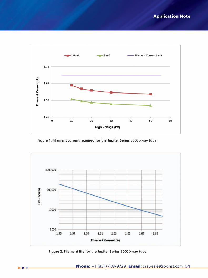
Phone: +1 (831) 439-9729 Email: [email protected] 51
Application Note
Figure 1: Filament current required for the Jupiter Series 5000 X-ray tube
Figure 2: Filament life for the Jupiter Series 5000 X-ray tube
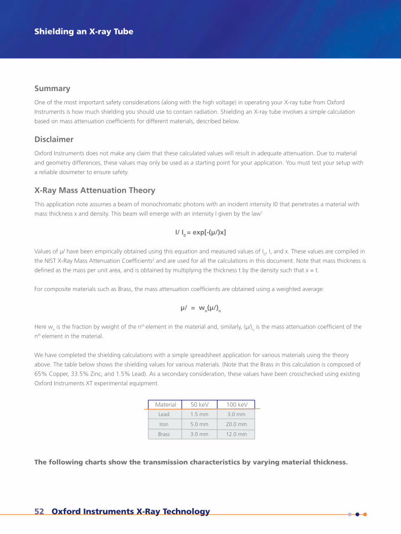
52 Oxford Instruments X-Ray Technology
Summary
One of the most important safety considerations (along with the high voltage) in operating your X-ray tube from Oxford
Instruments is how much shielding you should use to contain radiation. Shielding an X-ray tube involves a simple calculation
based on mass attenuation coefficients for different materials, described below.
Disclaimer
Oxford Instruments does not make any claim that these calculated values will result in adequate attenuation. Due to material
and geometry differences, these values may only be used as a starting point for your application. You must test your setup with
a reliable dosimeter to ensure safety.
X-Ray Mass Attenuation Theory
This application note assumes a beam of monochromatic photons with an incident intensity I0 that penetrates a material with
mass thickness x and density. This beam will emerge with an intensity I given by the law1
I/ I0 = exp[-(μ/)x]
Values of μ/ have been empirically obtained using this equation and measured values of I0, I, and x. These values are compiled in
the NIST X-Ray Mass Attenuation Coefficients2 and are used for all the calculations in this document. Note that mass thickness is
defined as the mass per unit area, and is obtained by multiplying the thickness t by the density such that x = t.
For composite materials such as Brass, the mass attenuation coefficients are obtained using a weighted average:
μ/ = wn(μ/)n
Here wn is the fraction by weight of the nth element in the material and, similarly, (μ/)n is the mass attenuation coefficient of the
nth element in the material.
We have completed the shielding calculations with a simple spreadsheet application for various materials using the theory
above. The table below shows the shielding values for various materials. (Note that the Brass in this calculation is composed of
65% Copper, 33.5% Zinc, and 1.5% Lead). As a secondary consideration, these values have been crosschecked using existing
Oxford Instruments XT experimental equipment.
Shielding an X-ray Tube
Material 50 keV
Lead
Iron
Brass
1.5 mm
5.0 mm
3.0 mm
100 keV
3.0 mm
20.0 mm
12.0 mm
The following charts show the transmission characteristics by varying material thickness.
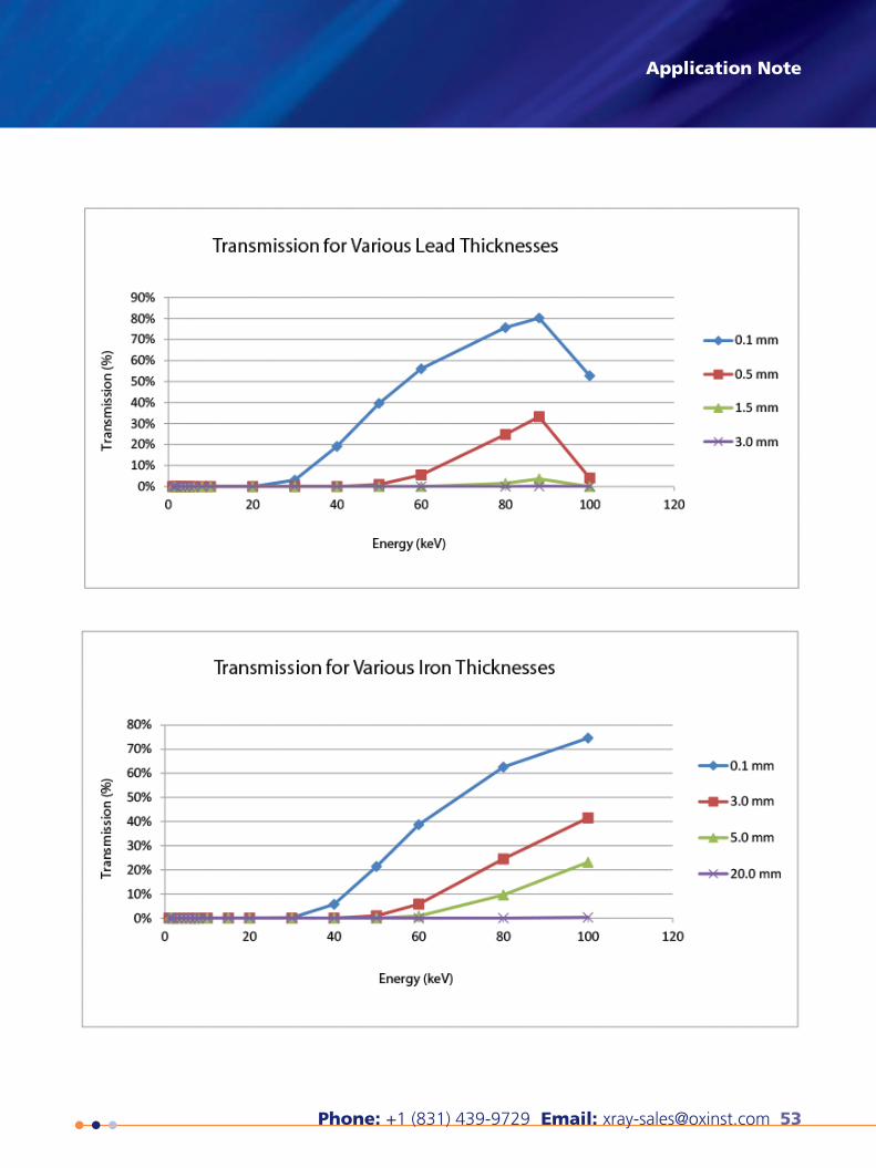
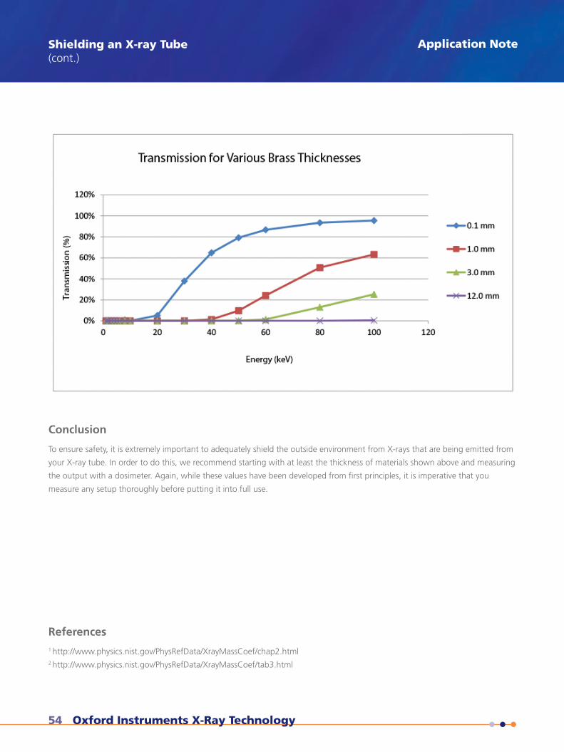
54 Oxford Instruments X-Ray Technology
Conclusion
To ensure safety, it is extremely important to adequately shield the outside environment from X-rays that are being emitted from
your X-ray tube. In order to do this, we recommend starting with at least the thickness of materials shown above and measuring
the output with a dosimeter. Again, while these values have been developed from first principles, it is imperative that you
measure any setup thoroughly before putting it into full use.
References 1 http://www.physics.nist.gov/PhysRefData/XrayMassCoef/chap2.html2 http://www.physics.nist.gov/PhysRefData/XrayMassCoef/tab3.html
Shielding an X-ray Tube(cont.)
Application Note
Phone: +1 (831) 439-9729 Email: [email protected] 55
The most frequent mode of failure of X-ray tubes is the failure to adequately dissipate the heat generated during normal
operation.
Greater than 99% of the kinetic energy imparted on the electron beam is lost in the form of heat at the anode target. Thus, a
50W X-ray tube will produce roughly 49.8W of energy in the form of heat just through the conversion process. Add to this the
thermal energy produced by the helical tungsten filament and one can readily see that heat dissipation is a major factor.
Inadequate cooling of an X-ray tube can cause it to fail in two ways.
The first is sublimation of the anode target material. In converting the anode target material directly from a solid to a gas
(sublimation), the resulting vapor rapidly degrades the internal high vacuum necessary for proper operation on the X-ray tube. The
loss of high vacuum results in a failure of the X-ray tube to withstand the high voltage gap between the cathode electron source
(helical tungsten filament) and the target anode. The X-ray tube begins to short circuit, or arc, which in turn liberates more gas
that further degrades the internal vacuum, resulting in an X-ray tube that no longer functions.
The second failure mode caused by improper heat dissipation is the liberation of damaging ions. If the X-ray tube anode is allowed
to surpass the vapor pressure point of the target material, ions will be liberated. These ions are attracted back toward the helical
tungsten filament and begin to erode the filament through an ion scrubbing process. This can cause the filament to break, creating
an open circuit.
Prevention of both of these failure modes is made possible by ensuring that the X-ray tube is not allowed to overheat. This means
careful monitoring of the cooling system with fault protection in the event of a cooling system failure.
Many of our packaged X-ray tubes offer an integrated thermal switch that helps prevent permanent damage to the X-ray tube.
Please confirm that your cooling system can maintain the temperature range that is recommended on our products.
Managing the Heat Produced by X-ray Tubes Application Note
56 Oxford Instruments X-Ray Technology
X-RAYImage credits
1. Image courtesy of Molecubes (see catalog back cover)
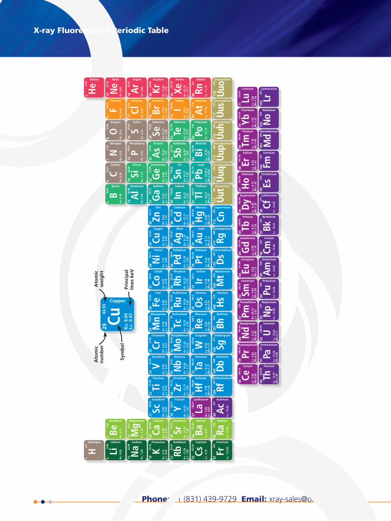
Phone: +1 (831) 439-9729 Email: [email protected] 57
UupUnunpentium
115
288
UuhUnunhexium
116
298
UusUnunseptium
117
294
UuoUnunoctium
118
294
Rh
Rhodium
45 Kα
20.
22
Lα 2
.7010
2.91
Pd
Palladium
46 Kα
21.
18
Lα 2
.8410
6.4
Ag
Silver
47 Kα
22.
16
Lα 2
.9810
7.87
Cd
Cadmium
48 Kα
23.
17
Lα 3
.1311
2.40
Ru
Ruthenium
44 Kα
19.
24
Lα 2
.5610
1.07
Tc
Technetium
43 Kα
18.
33
Lα 2
.42
99
Co
Cobalt
27 Kα
6.9
3
Lα 0
.7858
.93
Fe
Iron
26 Kα
6.4
0
Lα 0
.7055
.85
Ni
Nickel
28 Kα
7.4
7
Lα 0
.8558
.71
Cu
Copper
29 Kα
8.0
4
Lα 0
.9363
.55
Zn
Zinc
30 Kα
8.6
3
Lα 1
.0165
.37
Mn
Manganese
25 Kα
5.9
0
Lα 0
.6454
.94
Bi
Bismuth
83 Lα 1
0.39
M
α 2.
42208.
98
Po
Polonium
84 Lα 1
1.13
210
At
Astatine
85 Lα 1
1.43
210
Rn
Radon
86 Lα 1
1.73
222
Sb
Antimony
51 Kα
26.
36
Lα 3
.6012
1.75
Te
Tellurium
52 Kα
27.
47
Lα 3
.7712
7.60
I
Iodine
53 Kα
28.
61
Lα 3
.9412
6.90
Xe
Xenon
54 Kα
29.
78
Lα 4
.1113
1.30
SnTin
50 Kα
25.2
7
Lα 3
.4411
8.69
InIndium
49 Kα
24.
21
Lα 3
.2911
4.82
As
Arsenic
33 Kα
10.
53
Lα 1
.2874
.92
Ge
Germanium
32 Kα
9.8
8
Lα 1
.1972
.59
Se
Selenium
34 Kα
11.2
1
Lα 1
.3878
.96
Br
Bromine
35 Kα
11.
91
Lα 1
.4879
.90
Kr
Krypton
36 Kα
12.
63
Lα 1
.5983
.80
Ga
Gallium
31 Kα
9.2
4
Lα 1
.1069
.72
Nb
Niobium
41 Kα
16.
58
Lα 2
.1792
.91
Mo
Molybdenum
42 Kα
17.
45
Lα 2
.2995
.94
V
Vanadium
23 Kα
4.9
5
Lα 0
.5150
.94
Cr
Chromium
24 Kα
5.4
1
Lα 0
.5751
.99
Zr
Zirconium
40 Kα
15.
75
Lα 2
.0491
.22
Y
Yttrium
39 Kα
14.
93
Lα 1
.9288
.91
Ti
Titanium
22 Kα
4.5
1
Lα 0
.4547
.90
Sc
Scandium
21 Kα
4.09
Lα
0.4
044.9
6
Sr
Strontium
38 Kα
14.
14
Lα 1
.8187
.62
Rb
Rubidium
37 Kα
13.
38
Lα 1
.6985
.47
Ca
Calcium
20 Kα
3.6
9
Lα 0
.3440
.08
K
Potassium
19 Kα
3.31
Lα
0.2
6 39.1
0
UuqUnunquadium
114
298
UutUnuntrium
113
284
Mt
Meitnerium
109
276
Ds
Darmstadtium
110
281
RgRoentgenium
111
280
CnCopernicium
112
285
Hs
Hassium
108
270
Bh
Bohrium
107
272
Ir
Iridium
77 Lα 9
.18
M
α 1.
98
192.
2
Os
Osmium
76 Lα 8
.91
M
α 1.
91
190.
2
Pt
Platinum
78 Lα 9
.44
M
α 2.
05195.
09
Au
Gold
79 Lα 9
.71
M
α 2.
12196.
97
Hg
Mercury
80 Lα 9
.99
M
α 2.
20200.
59
Re
Rhenium
75 Lα 8
.65
M
α 1.
84
186.
2
Pb
Lead
82 Lα 1
0.55
17
Mα
2.34
26
207.
19
TlThallium
81 Lα 1
0.27
M
α 2.
27204.
37
Db
Dubnium
105
268
Sg
Seaborgium
106
271
Ta
Tantalum
73 Lα 8
.15
M
α 1.
71180.
95
W
Tungsten
74 Lα 8
.40
M
α 1.
77183.
85
Rf
Rutherfordium
104
267
Ac
Actinium
89 Lα 1
2.65
227
Hf
Hafnium
72 Lα 7
.90
M
α 1.
64178.
49
La
Lanthanum
57 Kα
4.65
Lα
0.8
3138.
91
Ra
Radium
88 Lα 1
2.34
226
Fr
Francium
87 Lα 1
2.03
2223
Ba
Barium
56 Lα 4
.4713
7.34
Cs
Caesium
55 Lα 4
.2913
2.91
Mg
Magnesium
12 Kα
1.2
5 24
.31
Na
Sodium
11 Kα
1.04
22.9
9
Be
Beryllium
4 Kα
0.1
1 9.
01
Li
Lithium
3 Kα
0.05
6.94
H
Hydrogen
11.
01
PPhosphorus
15 Kα
2.0
1 30
.97
Si
Silicon
14 Kα
1.7
4 28
.09
SSulfur
16 Kα
2.3
1 32
.06
Cl
Chlorine
17 Kα
2.6
2 35
.45
Ar
Argon
18 Kα
2.9
6 39
.95
Al
Aluminum
13 Kα
1.49
26.9
8
N
Nitrogen
7 Kα
0.3
9 0.
39
OOxygen
8 Kα
0.5
2 15
.99
FFluorine
9 Kα
0.6
8 18
.99
Ne
Neon
10 Kα
0.8
5 20
.18
C
Carbon
6 Kα
0.28
12.0
1
B
Boron
5 Kα
0.18
10.8
1
He
Helium
24.
00
Lr
Lawrencium
103
257
No
Nobelium
102
255
Cf
Californium
98 Lα 1
5.65
251
Es
Einsteinium
9925
4
Fm
Fermium
100
257
Md
Mendelevium
101
256
Bk
Berkelium
97 Lα 1
5.31
247
Cm
Curium
96 Lα 1
4.95
247
Dy
Dysprosium
66 Lα 6
.50
M
α 1.
29162.
50
Tb
Terbium
65 Lα 6
.27
M
α 1.
24158.
92
Ho
Holmium
67 Lα 6
.72
Mα
1.3516
4.93
Er
Erbium
68 Lα 6
.95
M
α 1.
41167.
26
Tm
Thulium
69 Lα 7
.18
M
α 1.
46168.
93
Gd
Gadolinium64 Lα
6.0
6
Mα
1.1915
7.25
Lu
Lutetium
71 Lα 7
.66
Mα
1.5817
4.97
Yb
Ytterbium
70 Lα 7
.42
M
α 1.
52173.
04
PuPlutonium
94 Lα 1
4.28
244
AmAmericium
95 Lα 1
4.62
243
Sm
Samarium
62 Lα 5
.64
M
α 1.
08150.
35
EuEuropium
63 Lα 5
.85
M
α 1.
13151.
96
Np
Neptunium
93 Lα 1
3.94
237
U
Uranium
92 Lα 1
3.61
M
α 3.
17238.
03
Pm
Promethium
61 Kα
38.
73
Lα 5
.43
145
Nd
Neodymium
60 Lα 5
.23
M
α 0.
98144.
24
Pa
Protactinium
91 Lα 1
3.29
M
α 3.
08
231
Th
Thorium
90 Lα 1
2.97
M
α 2.
99232.
04
Pr
Praseodymium
59 Lα 5
.03
M
α 0.
93140.
91
Ce
Cerium
58 Lα 4
.84
M
α 0.
88140.
12
UupUnunpentium
115
288
UuhUnunhexium
116
298
UusUnunseptium
117
294
UuoUnunoctium
118
294
Rh
Rhodium
45 Kα
20.
22
Lα 2
.7010
2.91
Pd
Palladium
46 Kα
21.
18
Lα 2
.8410
6.4
Ag
Silver
47 Kα
22.
16
Lα 2
.9810
7.87
Cd
Cadmium
48 Kα
23.
17
Lα 3
.1311
2.40
Ru
Ruthenium
44 Kα
19.
24
Lα 2
.5610
1.07
Tc
Technetium
43 Kα
18.
33
Lα 2
.42
99
Co
Cobalt
27 Kα
6.9
3
Lα 0
.7858
.93
Fe
Iron
26 Kα
6.4
0
Lα 0
.7055
.85
Ni
Nickel
28 Kα
7.4
7
Lα 0
.8558
.71
Cu
Copper
29 Kα
8.0
4
Lα 0
.9363
.55
Zn
Zinc
30 Kα
8.6
3
Lα 1
.0165
.37
Mn
Manganese
25 Kα
5.9
0
Lα 0
.6454
.94
Bi
Bismuth
83 Lα 1
0.39
M
α 2.
42208.
98
Po
Polonium
84 Lα 1
1.13
210
At
Astatine
85 Lα 1
1.43
210
Rn
Radon
86 Lα 1
1.73
222
SbAntimony
51 Kα
26.
36
Lα 3
.6012
1.75
Te
Tellurium
52 Kα
27.
47
Lα 3
.7712
7.60
I
Iodine
53 Kα
28.
61
Lα 3
.9412
6.90
Xe
Xenon
54 Kα
29.
78
Lα 4
.1113
1.30
Sn
Tin
50 Kα
25.2
7
Lα 3
.4411
8.69
In
Indium
49 Kα
24.
21
Lα 3
.2911
4.82
As
Arsenic
33 Kα
10.
53
Lα 1
.2874
.92
Ge
Germanium
32 Kα
9.8
8
Lα 1
.1972
.59
SeSelenium
34 Kα
11.2
1
Lα 1
.3878
.96
Br
Bromine
35 Kα
11.
91
Lα 1
.4879
.90
Kr
Krypton
36 Kα
12.
63
Lα 1
.5983
.80
Ga
Gallium
31 Kα
9.2
4
Lα 1
.1069
.72
Nb
Niobium
41 Kα
16.
58
Lα 2
.1792
.91
Mo
Molybdenum
42 Kα
17.
45
Lα 2
.2995
.94
V
Vanadium
23 Kα
4.9
5
Lα 0
.5150
.94
Cr
Chromium
24 Kα
5.4
1
Lα 0
.5751
.99
Zr
Zirconium
40 Kα
15.
75
Lα 2
.0491
.22
Y
Yttrium
39 Kα
14.
93
Lα 1
.9288
.91
Ti
Titanium
22 Kα
4.5
1
Lα 0
.4547
.90
Sc
Scandium
21 Kα
4.09
Lα
0.4
044.9
6
Sr
Strontium
38 Kα
14.
14
Lα 1
.8187
.62
Rb
Rubidium
37 Kα
13.
38
Lα 1
.6985
.47
Ca
Calcium
20 Kα
3.6
9
Lα 0
.3440
.08
K
Potassium
19 Kα
3.31
Lα
0.2
6 39.1
0
UuqUnunquadium
114
298
UutUnuntrium
113
284
Mt
Meitnerium
109
276
Ds
Darmstadtium
110
281
Rg
Roentgenium
111
280
Cn
Copernicium
112
285
Hs
Hassium
108
270
Bh
Bohrium
107
272
Ir
Iridium
77 Lα 9
.18
M
α 1.
98
192.
2
Os
Osmium
76 Lα 8
.91
M
α 1.
91
190.
2
Pt
Platinum
78 Lα 9
.44
M
α 2.
05195.
09
Au
Gold
79 Lα 9
.71
M
α 2.
12196.
97
Hg
Mercury
80 Lα 9
.99
M
α 2.
20200.
59
Re
Rhenium
75 Lα 8
.65
M
α 1.
84
186.
2
PbLead
82 Lα 1
0.55
17
Mα
2.34
26
207.
19
Tl
Thallium
81 Lα 1
0.27
M
α 2.
27204.
37
Db
Dubnium
105
268
Sg
Seaborgium
106
271
Ta
Tantalum
73 Lα 8
.15
M
α 1.
71180.
95
W
Tungsten
74 Lα 8
.40
M
α 1.
77183.
85
Rf
Rutherfordium
104
267
Ac
Actinium
89 Lα 1
2.65
227
Hf
Hafnium
72 Lα 7
.90
M
α 1.
64178.
49
La
Lanthanum
57 Kα
4.65
Lα
0.8
3138.
91
Ra
Radium
88 Lα 1
2.34
226
Fr
Francium
87 Lα 1
2.03
2223
Ba
Barium
56 Lα 4
.4713
7.34
Cs
Caesium
55 Lα 4
.2913
2.91
Mg
Magnesium
12 Kα
1.2
5 24
.31
Na
Sodium
11 Kα
1.04
22.9
9
Be
Beryllium
4 Kα
0.1
1 9.
01
Li
Lithium
3 Kα
0.05
6.94
H
Hydrogen
11.
01
P
Phosphorus
15 Kα
2.0
1 30
.97
Si
Silicon
14 Kα
1.7
4 28
.09
S
Sulfur
16 Kα
2.3
1 32
.06
ClChlorine
17 Kα
2.6
2 35
.45
Ar
Argon
18 Kα
2.9
6 39
.95
Al
Aluminum
13 Kα
1.49
26.9
8
N
Nitrogen
7 Kα
0.3
9 0.
39
O
Oxygen
8 Kα
0.5
2 15
.99
F
Fluorine
9 Kα
0.6
8 18
.99
Ne
Neon
10 Kα
0.8
5 20
.18
C
Carbon
6 Kα
0.28
12.0
1
B
Boron
5 Kα
0.18
10.8
1
He
Helium
24.
00
Lr
Lawrencium
103
257
No
Nobelium
102
255
Cf
Californium
98 Lα 1
5.65
251
Es
Einsteinium
9925
4
Fm
Fermium
100
257
Md
Mendelevium
101
256
Bk
Berkelium
97 Lα 1
5.31
247
CmCurium
96 Lα 1
4.95
247
Dy
Dysprosium
66 Lα 6
.50
M
α 1.
29162.
50
TbTerbium
65 Lα 6
.27
M
α 1.
24158.
92
Ho
Holmium
67 Lα 6
.72
Mα
1.3516
4.93
Er
Erbium
68 Lα 6
.95
M
α 1.
41167.
26
Tm
Thulium
69 Lα 7
.18
M
α 1.
46168.
93
Gd
Gadolinium
64 Lα 6
.06
M
α 1.
19157.
25
Lu
Lutetium
71 Lα 7
.66
Mα
1.5817
4.97
Yb
Ytterbium
70 Lα 7
.42
M
α 1.
52173.
04
Pu
Plutonium
94 Lα 1
4.28
244
Am
Americium
95 Lα 1
4.62
243
Sm
Samarium
62 Lα 5
.64
M
α 1.
08150.
35
Eu
Europium
63 Lα 5
.85
M
α 1.
13151.
96
Np
Neptunium
93 Lα 1
3.94
237
U
Uranium
92 Lα 1
3.61
M
α 3.
17238.
03
Pm
Promethium
61 Kα
38.
73
Lα 5
.43
145
Nd
Neodymium
60 Lα 5
.23
M
α 0.
98144.
24
Pa
Protactinium
91 Lα 1
3.29
M
α 3.
08
231
Th
Thorium
90 Lα 1
2.97
M
α 2.
99232.
04
Pr
Praseodymium
59 Lα 5
.03
M
α 0.
93140.
91
Ce
Cerium
58 Lα 4
.84
M
α 0.
88140.
12
Key
Ato
mic
wei
gh
t
Sym
bo
l
Ato
mic
nu
mb
er
Prin
cip
al
lines
keV
UupUnunpentium
115
288
UuhUnunhexium
116
298
UusUnunseptium
117
294
UuoUnunoctium
118
294
Rh
Rhodium
45 Kα
20.
22
Lα 2
.7010
2.91
Pd
Palladium
46 Kα
21.
18
Lα 2
.8410
6.4
Ag
Silver
47 Kα
22.
16
Lα 2
.9810
7.87
Cd
Cadmium
48 Kα
23.
17
Lα 3
.1311
2.40
Ru
Ruthenium
44 Kα
19.
24
Lα 2
.5610
1.07
Tc
Technetium
43 Kα
18.
33
Lα 2
.42
99
Co
Cobalt
27 Kα
6.9
3
Lα 0
.7858
.93
Fe
Iron
26 Kα
6.4
0
Lα 0
.7055
.85
Ni
Nickel
28 Kα
7.4
7
Lα 0
.8558
.71
Cu
Copper
29 Kα
8.0
4
Lα 0
.9363
.55
Zn
Zinc
30 Kα
8.6
3
Lα 1
.0165
.37
Mn
Manganese
25 Kα
5.9
0
Lα 0
.6454
.94
Bi
Bismuth
83 Lα 1
0.39
M
α 2.
42208.
98
Po
Polonium
84 Lα 1
1.13
210
At
Astatine
85 Lα 1
1.43
210
Rn
Radon
86 Lα 1
1.73
222
Sb
Antimony
51 Kα
26.
36
Lα 3
.6012
1.75
Te
Tellurium
52 Kα
27.
47
Lα 3
.7712
7.60
I
Iodine
53 Kα
28.
61
Lα 3
.9412
6.90
Xe
Xenon
54 Kα
29.
78
Lα 4
.1113
1.30
SnTin
50 Kα
25.2
7
Lα 3
.4411
8.69
InIndium
49 Kα
24.
21
Lα 3
.2911
4.82
As
Arsenic33 K
α 1
0.53
Lα
1.2
874.9
2
Ge
Germanium
32 Kα
9.8
8
Lα 1
.1972
.59
Se
Selenium
34 Kα
11.2
1
Lα 1
.3878
.96
Br
Bromine
35 Kα
11.
91
Lα 1
.4879
.90
Kr
Krypton
36 Kα
12.
63
Lα 1
.5983
.80
Ga
Gallium
31 Kα
9.2
4
Lα 1
.1069
.72
Nb
Niobium
41 Kα
16.
58
Lα 2
.1792
.91
Mo
Molybdenum
42 Kα
17.
45
Lα 2
.2995
.94
V
Vanadium
23 Kα
4.9
5
Lα 0
.5150
.94
Cr
Chromium
24 Kα
5.4
1
Lα 0
.5751
.99
Zr
Zirconium
40 Kα
15.
75
Lα 2
.0491
.22
Y
Yttrium
39 Kα
14.
93
Lα 1
.9288
.91
Ti
Titanium
22 Kα
4.5
1
Lα 0
.4547
.90
Sc
Scandium
21 Kα
4.09
Lα
0.4
044.9
6
Sr
Strontium
38 Kα
14.
14
Lα 1
.8187
.62
Rb
Rubidium
37 Kα
13.
38
Lα 1
.6985
.47
Ca
Calcium
20 Kα
3.6
9
Lα 0
.3440
.08
K
Potassium
19 Kα
3.31
Lα
0.2
6 39.1
0
UuqUnunquadium
114
298
UutUnuntrium
113
284
Mt
Meitnerium
109
276
Ds
Darmstadtium
110
281
RgRoentgenium
111
280
CnCopernicium
112
285
Hs
Hassium
108
270
Bh
Bohrium
107
272
Ir
Iridium
77 Lα 9
.18
M
α 1.
98
192.
2
Os
Osmium
76 Lα 8
.91
M
α 1.
91
190.
2
Pt
Platinum
78 Lα 9
.44
M
α 2.
05195.
09
Au
Gold
79 Lα 9
.71
M
α 2.
12196.
97
Hg
Mercury
80 Lα 9
.99
M
α 2.
20200.
59
Re
Rhenium
75 Lα 8
.65
M
α 1.
84
186.
2
Pb
Lead
82 Lα 1
0.55
17
Mα
2.34
26
207.
19
TlThallium
81 Lα 1
0.27
M
α 2.
27204.
37
Db
Dubnium
105
268
Sg
Seaborgium
106
271
Ta
Tantalum
73 Lα 8
.15
M
α 1.
71180.
95
W
Tungsten
74 Lα 8
.40
M
α 1.
77183.
85
Rf
Rutherfordium
104
267
Ac
Actinium
89 Lα 1
2.65
227
Hf
Hafnium
72 Lα 7
.90
M
α 1.
64178.
49
La
Lanthanum
57 Kα
4.65
Lα
0.8
3138.
91
Ra
Radium
88 Lα 1
2.34
226
Fr
Francium
87 Lα 1
2.03
2223
Ba
Barium
56 Lα 4
.4713
7.34
Cs
Caesium
55 Lα 4
.2913
2.91
Mg
Magnesium
12 Kα
1.2
5 24
.31
Na
Sodium
11 Kα
1.04
22.9
9
Be
Beryllium
4 Kα
0.1
1 9.
01
Li
Lithium
3 Kα
0.05
6.94
H
Hydrogen
11.
01
PPhosphorus
15 Kα
2.0
1 30
.97
Si
Silicon
14 Kα
1.7
4 28
.09
SSulfur
16 Kα
2.3
1 32
.06
Cl
Chlorine
17 Kα
2.6
2 35
.45
Ar
Argon
18 Kα
2.9
6 39
.95
Al
Aluminum
13 Kα
1.49
26.9
8
N
Nitrogen
7 Kα
0.3
9 0.
39
OOxygen
8 Kα
0.5
2 15
.99
FFluorine
9 Kα
0.6
8 18
.99
Ne
Neon
10 Kα
0.8
5 20
.18
C
Carbon
6 Kα
0.28
12.0
1
B
Boron
5 Kα
0.18
10.8
1
He
Helium2
4.00
Lr
Lawrencium
103
257
No
Nobelium
102
255
Cf
Californium
98 Lα 1
5.65
251
Es
Einsteinium
9925
4
Fm
Fermium
100
257
Md
Mendelevium
101
256
Bk
Berkelium
97 Lα 1
5.31
247
Cm
Curium
96 Lα 1
4.95
247
Dy
Dysprosium
66 Lα 6
.50
M
α 1.
29162.
50
Tb
Terbium
65 Lα 6
.27
M
α 1.
24158.
92
Ho
Holmium
67 Lα 6
.72
Mα
1.3516
4.93
Er
Erbium
68 Lα 6
.95
M
α 1.
41167.
26
Tm
Thulium
69 Lα 7
.18
M
α 1.
46168.
93
Gd
Gadolinium64 Lα
6.0
6
Mα
1.1915
7.25
Lu
Lutetium
71 Lα 7
.66
Mα
1.5817
4.97
Yb
Ytterbium
70 Lα 7
.42
M
α 1.
52173.
04
PuPlutonium
94 Lα 1
4.28
244
AmAmericium
95 Lα 1
4.62
243
Sm
Samarium
62 Lα 5
.64
M
α 1.
08150.
35
EuEuropium
63 Lα 5
.85
M
α 1.
13151.
96
Np
Neptunium
93 Lα 1
3.94
237
U
Uranium
92 Lα 1
3.61
M
α 3.
17238.
03
Pm
Promethium
61 Kα
38.
73
Lα 5
.43
145
Nd
Neodymium
60 Lα 5
.23
M
α 0.
98144.
24
Pa
Protactinium
91 Lα 1
3.29
M
α 3.
08
231
Th
Thorium
90 Lα 1
2.97
M
α 2.
99232.
04
Pr
Praseodymium
59 Lα 5
.03
M
α 0.
93140.
91
Ce
Cerium
58 Lα 4
.84
M
α 0.
88140.
12
X-RAY X-ray Fluorescence Periodic Table

Oxford Instruments X-Ray Technology
X-RAY
This publication is the copyright of Oxford Instruments plc and provides outline information only, which (unless agreedby the company in writing) may not be used, applied or reproduced for any purpose or form part of any order orcontract or regarded as the representation relating to the products or services concerned. Oxford Instruments’ policyis one of continued improvement. The company reserves the right to alter, without notice the specification, design orconditions of supply of any product or service. Oxford Instruments acknowledges all trademarks and registrations.© Oxford Instruments plc, 2016. All rights reserved. Document reference: Part no: 3900003 - April 4, 2016
X-ray Fluorescence Industrial Inspection Medical Imaging
Metal Analysisand Identification
Printed Circuit BoardDrilling and Inspection
Bone and TissueImaging
Energy and Mining Food and PackagingSafety
Small Animaland Drug Studies1
Visit www.oxford-instruments.com/xt or [email protected] for more information
X-Ray Technology360 El Pueblo Road, Suite 104Scotts Valley, CA 95066, USA
Phone: +1 (831) 439-9729Fax: +1 (831) 439-6050Email: [email protected]