2016 annual inspection report vertical extension landfill
TRANSCRIPT
Prepared for
DTE Electric Company One Energy Plaza
Detroit, Michigan 48226
2016 ANNUAL INSPECTION REPORT VERTICAL EXTENSION LANDFILL
MONROE POWER PLANT
Monroe, Michigan
Prepared by
134 North La Salle Street, Suite 300 Chicago, Illinois 60602
CHE8242H9
January 2017
CHE8242\2017-01-VertExt-Annual Inspection Report
i January 2017
TABLE OF CONTENTS
1. INTRODUCTION ................................................................................................................ 1-1
1.1 Overview ....................................................................................................................... 1-1
1.2 Purpose .......................................................................................................................... 1-1
1.3 Report Organization ...................................................................................................... 1-2
1.4 Terms of Reference ....................................................................................................... 1-2
2. review of available information ........................................................................................... 2-1
3. FACILITY DESCRIPTION ................................................................................................. 3-1
3.1 Overall Site Description ................................................................................................ 3-1
3.2 Design............................................................................................................................ 3-1
3.3 Construction .................................................................................................................. 3-3
4. VISUAL INSPECTION RESULTS ..................................................................................... 4-1
5. INSTRUMENTATION MONITORING ............................................................................. 5-1
5.1 Slope Inclinometers ....................................................................................................... 5-1
5.2 Piezometers ................................................................................................................... 5-1
5.3 Settlement Plates ........................................................................................................... 5-1
6. OPERATION ACTIVITIES ................................................................................................ 6-1
6.1 Operations Organization ............................................................................................... 6-1
6.2 Operation Activities ...................................................................................................... 6-1
6.3 Observations .................................................................................................................. 6-2
7. EVALUATION .................................................................................................................... 7-1
7.1 Design............................................................................................................................ 7-1
CHE8242\2017-01-VertExt-Annual Inspection Report
ii January 2017
7.2 Construction .................................................................................................................. 7-1
7.3 Maintenance .................................................................................................................. 7-1
7.4 Operations ..................................................................................................................... 7-1
7.4.1 Operations Plan .................................................................................................. 7-1
7.4.2 Fugitive Dust Plan .............................................................................................. 7-1
7.4.3 Run on and Run off Control ............................................................................... 7-2
7.4.4 Inspections .......................................................................................................... 7-2
7.4.5 Monitoring .......................................................................................................... 7-2
7.4.6 Annual Visual Inspection ................................................................................... 7-2
8. CONCLUSIONS AND CERTIFICATION ......................................................................... 8-1
LIST OF TABLES
Table 1: Available Information Reviewed for Annual Inspection
LIST OF FIGURES
Figure 1: Site Location
LIST OF APPENDICES
Appendix A Resume of the Qualified Professional Engineer
Appendix B 2016 Landfill Visual Inspection Checklist and Photographs
Appendix C Instrumentation Locations
Appendix D Operational Information
CHE8242\2017-01-VertExt-Annual Inspection Report
1-1 January 2017
1. INTRODUCTION
1.1 Overview
This 2016 Annual Inspection Report (AIR) was prepared by Geosyntec Consultants (Geosyntec) to provide the results of the annual inspection of the coal combustion residuals (CCR) vertical extension landfill (Landfill) at the DTE Electric Company (DTE) Monroe Power Plant disposal facility. The annual inspection has been prepared to comply with United States Environmental Protection Agency (USEPA) Coal Combustion Residuals Rule (CCR Rule) published on April 17, 2015 (40 CFR 257.84). Under the CCR Rule, the Landfill is an “existing landfill” per 40 CFR 257.53 and must be inspected by a qualified professional engineer on a periodic basis, not to exceed one year.
The Landfill is located about one mile southwest of the Monroe Power Plant near Monroe, Michigan, and is bounded on the east by Lake Erie and the Plant discharge canal, on the west by Interstate Highway 75 (I-75), on the south by an agricultural field, and on the north by residential property and Plum Creek (see Figure 1). It is constructed on top of fly ash that was previously deposited in the Monroe Ash Basin. The combined Landfill and Ash Basin is considered the “Permitted Area”.
Landfill Phase 1 construction began in August 2015, the Michigan Department of Environmental Quality (MDEQ) licensed the area for disposal via email communication on October 14, 2015, and CCR was placed in the unit beginning October 16, 2015. CCR disposal continued after 19 October 20151 as witnessed during the current annual inspection in September 2016. Landfill construction is ongoing and continuous for remaining phases.
1.2 Purpose
The purpose of the inspection under the CCR Rule [40 CFR 257.84(b)(1)] is:
“…to ensure that the design, construction, operation, and maintenance of the CCR unit is consistent with recognized and generally accepted good engineering standards. The inspection must, at a minimum, include:
1 Based on the CCR Rule, existing landfill is “…landfill that receives CCR both before and after October 19, 2015, or for which construction commenced prior to October 19, 2015 and receives CCR on or after October 19, 2015…”.
CHE8242\2017-01-VertExt-Annual Inspection Report
1-2 January 2017
(i) A review of available information regarding the status and condition of the CCR unit, including, but not limited to, files available in the operating record (e.g., the results of inspection by a qualified person, and results of previous annual inspections); and
(ii) A visual inspection of the CCR unit to identify signs of distress or malfunction of the CCR unit.”
The purpose is accomplished through periodic visual inspection (and photo-documentation) of the Landfill, review of instrumentation monitoring data and evaluations intended to detect signs of instability, and review of construction certification documentation, and review of operating records over 2016.
1.3 Report Organization
The remainder of this report is organized as follows:
• Section 2 – Review of available information: summarizes various historical documents that were reviewed as part of this inspection
• Section 3 – Facility Description: provides information about the facility
• Section 4 – Visual Inspection Results: summarizes visual observations recorded during inspections of the Landfill
• Section 5 – Instrumentation Monitoring: provides information about the instrumentation monitoring
• Section 6 – Operation Activities: describes the operations organization and activities
• Section 7 – Evaluation: evaluates the results of the annual inspection
• Section 8 – Conclusions and Certification: provides the overall conclusions of the annual inspection
1.4 Terms of Reference
The annual visual inspection was performed by Mr. John Seymour, P.E. of Geosyntec whose qualifications as a “qualified professional engineer” under the CCR Rule are presented in Appendix A. DTE’s “qualified person”, who conducts the weekly inspections, accompanied Mr. Seymour.

CHE8242\2017-01-VertExt-Annual Inspection Report
1-3 January 2017
This report was prepared by Mr. John Seymour, P.E. of Geosyntec. The peer review was completed by Mr. Omer Bozok, P.E. of Geosyntec. John Seymour, P.E. and Omer Bozok, P.E. of Geosyntec are qualified professional engineers per the requirements of §257.53 of the CCR Rule. Both engineers have been heavily involved with the Site since 2009, the initiation of the design and construction efforts for the mitigation of the ash basin embankment.
CHE8242\2017-01-VertExt-Annual Inspection Report
2-1 January 2017
2. REVIEW OF AVAILABLE INFORMATION
Geosyntec reviewed the following documents for the annual inspection. These documents are summarized in the table below.
Table 1: Available Information Reviewed for Annual Inspection
Title Prepared by Year Content
Operations and Monitoring Plan, DTE Energy Monroe Power Plant and Ash Basin
Golder April 16, 2015 Appendix G contained in the Permit Modification Application Report (16 April 2015)
Construction Quality Assurance Plan MPP Fly Ash Basin Overliner Construction”
Golder April 16, 2015 Appendix H contained in the Permit Modification Application Report (16 April 2015)
Fugitive Dust Plan DTE 20152 Presents dust control measures.
Weekly Inspection Reports DTE Energy 2016
Qualified person inspections from December 2015 through September 2016 (time of inspection)
CCR disposal records (Excel spreadsheet) Headwaters 2016 Documentation of waste tonnage placed in
the CCR landfill
Closure Plan AECOM October 2016 Documenting how the plan will meet the CCR Rule.
Post-Closure Plan AECOM October 2016 Documenting how the plan will meet the CCR Rule.
2 The Fugitive Dust Plan (FDP) is not dated but DTE reported to Geosyntec that the FDP is based on an EPRI template completed in September 2015; therefore, the date is simply identified as “2015”.
CHE8242\2017-01-VertExt-Annual Inspection Report
2-2 January 2017
Title Prepared by Year Content
Run-on/Run-off Plan AECOM October 2016 Documenting how the plan meets the CCR Rule.
Headwaters Letter & DTE email
Headwaters & DTE
April 2016 & November 2016, respectively
Documenting the training of operations personnel per the Operating Plan
CHE8242\2017-01-VertExt-Annual Inspection Report
3-1 January 2017
3. FACILITY DESCRIPTION
3.1 Overall Site Description
The permitted facility description includes a 79-acre vertical extension landfill (Landfill) and 331-acre fly ash basin (Ash Basin) for a permitted area of 410 acres. The permitted area is located in Section 16, Township 7 south, Range 9 east, of Monroe Township, Michigan shown on Figure 1. The Landfill is a Type III low-hazard industrial waste landfill. The Ash Basin is a Type III industrial waste surface impoundment. The Landfill is licensed with the Ash Basin under Michigan Part 115, Solid Waste Management, of the Natural Resources and Environmental Protection Act, 1994 License No. 9393, issued on 12 June 2014 and expires on 12 June 2019.
The Landfill is designated as a 79 acre “dry” disposal area located on top of an area of the Ash Basin that has been filled with CCR approximately to the originally planned final grade. The site investigation conducted in 2015 identified the fly ash below the Landfill to be approximately 40 feet deep from preconstruction ground surface. The maximum water level in the Ash Basin is maintained around 609 ft.
The Landfill is licensed to receive bottom ash, fly ash, flue gas desulfurization (FGD) scrubber wastewater sludge, solidified with fly ash or bottom ash, synthetic gypsum, inert material and any other waste allowed by Rule or obtained through specific regulatory approval (Permit Modification Report, Golder, 2015).
Phase 1 of the Landfill, finished in September 2015, is the western 11-acre portion shown on Figure 1. Record drawings of the construction were provided in Appendix B of the 2015 Annual Report. Additional construction of areas to the east are underway but have not been certified as completed.
3.2 Design
The design was provided by Golder in the Permit Modification report (April 16, 2015). The components of the Landfill include:
• Perimeter Collection Swale
• Prepared subgrade consisting of in-situ sluiced fly ash and placed general fill;
• 30-inch thick pore pressure relief layer, including from the bottom up, of:
o 24-inches of bottom ash or limestone
CHE8242\2017-01-VertExt-Annual Inspection Report
3-2 January 2017
o Perforated collection piping encased in a filter fabric (“sock”)
o Separation geotextile, non-woven, needle-punched geotextile
o 6-inch embedment layer
• Perimeter berm.
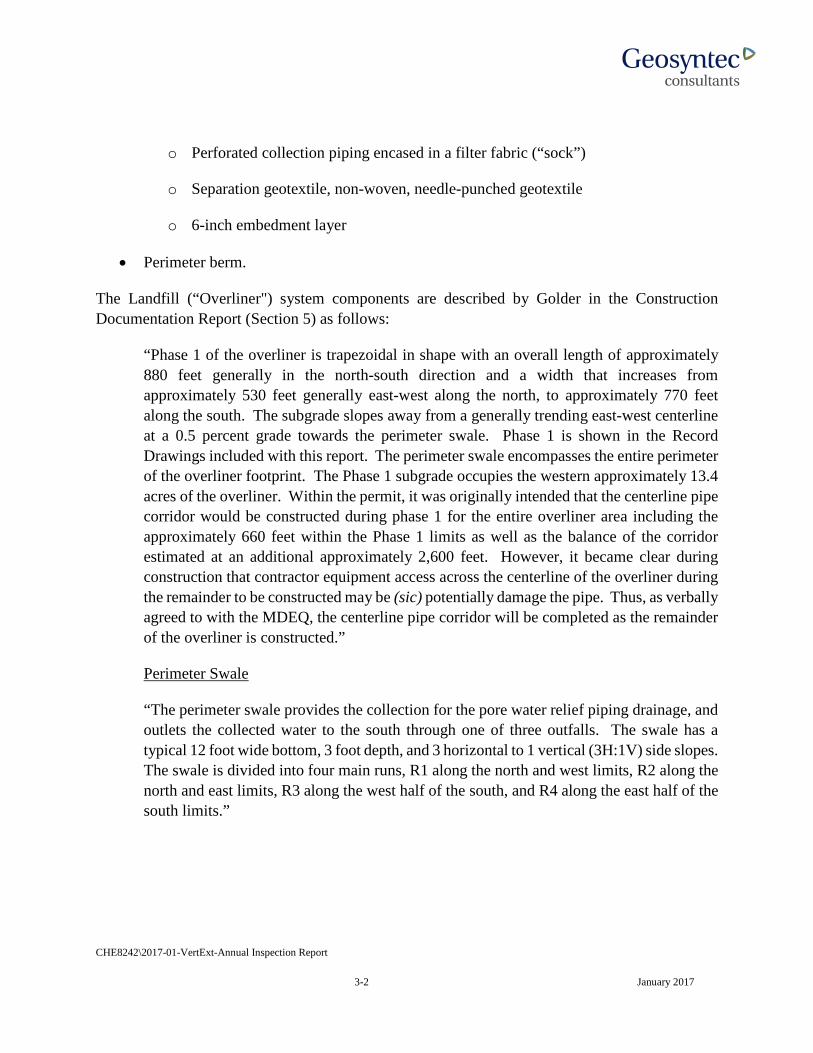
The Landfill (“Overliner") system components are described by Golder in the Construction Documentation Report (Section 5) as follows:
“Phase 1 of the overliner is trapezoidal in shape with an overall length of approximately 880 feet generally in the north-south direction and a width that increases from approximately 530 feet generally east-west along the north, to approximately 770 feet along the south. The subgrade slopes away from a generally trending east-west centerline at a 0.5 percent grade towards the perimeter swale. Phase 1 is shown in the Record Drawings included with this report. The perimeter swale encompasses the entire perimeter of the overliner footprint. The Phase 1 subgrade occupies the western approximately 13.4 acres of the overliner. Within the permit, it was originally intended that the centerline pipe corridor would be constructed during phase 1 for the entire overliner area including the approximately 660 feet within the Phase 1 limits as well as the balance of the corridor estimated at an additional approximately 2,600 feet. However, it became clear during construction that contractor equipment access across the centerline of the overliner during the remainder to be constructed may be (sic) potentially damage the pipe. Thus, as verbally agreed to with the MDEQ, the centerline pipe corridor will be completed as the remainder of the overliner is constructed.”
Perimeter Swale
“The perimeter swale provides the collection for the pore water relief piping drainage, and outlets the collected water to the south through one of three outfalls. The swale has a typical 12 foot wide bottom, 3 foot depth, and 3 horizontal to 1 vertical (3H:1V) side slopes. The swale is divided into four main runs, R1 along the north and west limits, R2 along the north and east limits, R3 along the west half of the south, and R4 along the east half of the south limits.”
CHE8242\2017-01-VertExt-Annual Inspection Report
3-3 January 2017
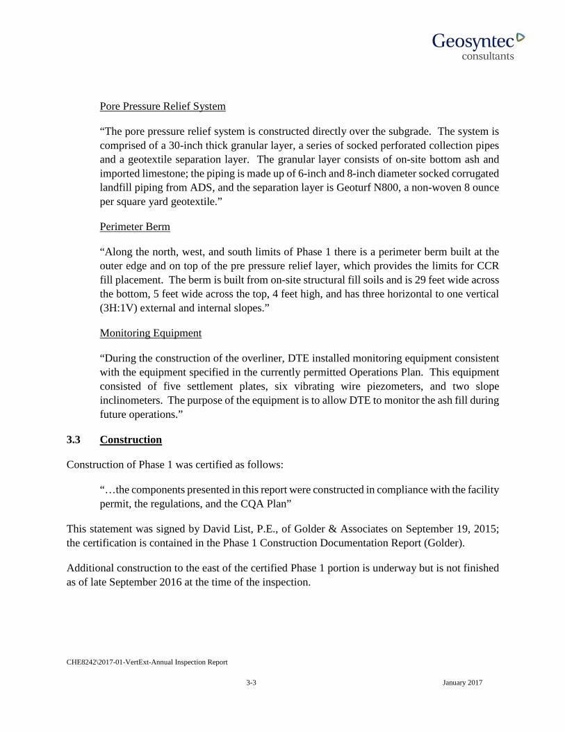
Pore Pressure Relief System
“The pore pressure relief system is constructed directly over the subgrade. The system is comprised of a 30-inch thick granular layer, a series of socked perforated collection pipes and a geotextile separation layer. The granular layer consists of on-site bottom ash and imported limestone; the piping is made up of 6-inch and 8-inch diameter socked corrugated landfill piping from ADS, and the separation layer is Geoturf N800, a non-woven 8 ounce per square yard geotextile.”
Perimeter Berm
“Along the north, west, and south limits of Phase 1 there is a perimeter berm built at the outer edge and on top of the pre pressure relief layer, which provides the limits for CCR fill placement. The berm is built from on-site structural fill soils and is 29 feet wide across the bottom, 5 feet wide across the top, 4 feet high, and has three horizontal to one vertical (3H:1V) external and internal slopes.”
Monitoring Equipment
“During the construction of the overliner, DTE installed monitoring equipment consistent with the equipment specified in the currently permitted Operations Plan. This equipment consisted of five settlement plates, six vibrating wire piezometers, and two slope inclinometers. The purpose of the equipment is to allow DTE to monitor the ash fill during future operations.”
3.3 Construction
Construction of Phase 1 was certified as follows:
“…the components presented in this report were constructed in compliance with the facility permit, the regulations, and the CQA Plan”
This statement was signed by David List, P.E., of Golder & Associates on September 19, 2015; the certification is contained in the Phase 1 Construction Documentation Report (Golder).
Additional construction to the east of the certified Phase 1 portion is underway but is not finished as of late September 2016 at the time of the inspection.
CHE8242\2017-01-VertExt-Annual Inspection Report
4-1 January 2017
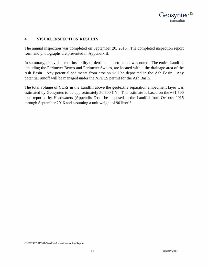
4. VISUAL INSPECTION RESULTS
The annual inspection was completed on September 20, 2016. The completed inspection report form and photographs are presented in Appendix B.
In summary, no evidence of instability or detrimental settlement was noted. The entire Landfill, including the Perimeter Berms and Perimeter Swales, are located within the drainage area of the Ash Basin. Any potential sediments from erosion will be deposited in the Ash Basin. Any potential runoff will be managed under the NPDES permit for the Ash Basin.
The total volume of CCRs in the Landfill above the geotextile separation embedment layer was estimated by Geosyntec to be approximately 50,600 CY. This estimate is based on the ~61,500 tons reported by Headwaters (Appendix D) to be disposed in the Landfill from October 2015 through September 2016 and assuming a unit weight of 90 lbs/ft3.

CHE8242\2017-01-VertExt-Annual Inspection Report
5-1 January 2017
5. INSTRUMENTATION MONITORING
5.1 Slope Inclinometers
Slope inclinometer (SI) locations (2) are shown on Figure 8 in Appendix C. Inclinometers SI-9 and SI-10 have been monitored upon installation and prior to filling operations. Subsequent readings were obtained at least monthly for the SIs since February 2016.
5.2 Piezometers
Piezometer locations are shown on Figure 8 in Appendix C. The six piezometers have been monitored from February through September 2016 on at least a monthly basis.
5.3 Settlement Plates
Phase 1 settlement plate (SP) locations (3) are shown on Figure 8 in Appendix C. SP-3, SP-4, and SP-5 have been read upon installation and prior to filling operations. Subsequent readings were obtained at least monthly since February 2016. SP-1 and SP-2 are associated with ongoing construction to the east of the certified portion in Phase 1 and are not required to be read until after certification of construction. However, SP-1 has been read since June 2016 and SP-2 has been read since February 2016.
CHE8242\2017-01-VertExt-Annual Inspection Report
6-1 January 2017
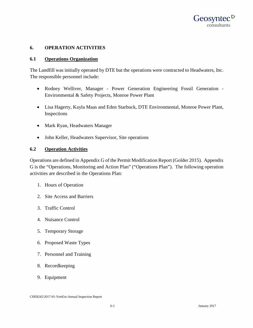
6. OPERATION ACTIVITIES
6.1 Operations Organization
The Landfill was initially operated by DTE but the operations were contracted to Headwaters, Inc. The responsible personnel include:
• Rodney Welliver, Manager - Power Generation Engineering Fossil Generation - Environmental & Safety Projects, Monroe Power Plant
• Lisa Hagerty, Kayla Maas and Eden Starbuck, DTE Environmental, Monroe Power Plant, Inspections
• Mark Ryan, Headwaters Manager
• John Keller, Headwaters Supervisor, Site operations
6.2 Operation Activities
Operations are defined in Appendix G of the Permit Modification Report (Golder 2015). Appendix G is the “Operations, Monitoring and Action Plan” (“Operations Plan”). The following operation activities are described in the Operations Plan:
1. Hours of Operation
2. Site Access and Barriers
3. Traffic Control
4. Nuisance Control
5. Temporary Storage
6. Proposed Waste Types
7. Personnel and Training
8. Recordkeeping
9. Equipment

CHE8242\2017-01-VertExt-Annual Inspection Report
6-2 January 2017
10. Filling Operations
11. Intermediate Cover Use
12. Water
13. Bottom Ash
14. Soil Cover
15. Chemical Sprays
16. Geotextiles and Rolled Erosion Control Products
17. Intermediate Cover Use Summary
The Operations Plan was written by DTE/Golder and approved by MDEQ in the 31 July 2015 construction permit.
In addition, the following are specifically currently required by the CCR Rule:
• Weekly inspections by a qualified person, and
• Dust control in accordance with a Fugitive Dust Control Plan.3
6.3 Observations
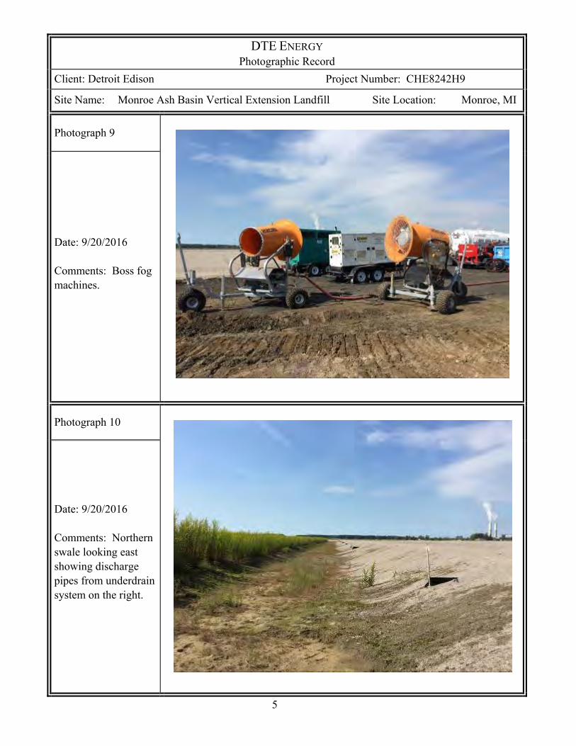
It was identified that the overall intent of the Operations Plan was being followed. Items 11 and 13 through 17 were not applicable at the time of the inspection. DTE employs two Boss “fog” applicators (Photo 9), referred to as “Dust Bosses”, when emptying vacuum boxes filled with fly ash. Water trucks spray either water or “Dustabate” for dust suppression for roads to reduce dusting.
3 DTE reported to Geosyntec on December 22, 2015 that there is only one FDP for the combined Ash Basin and Landfill. This FDP is posted on the DTE’s CCR Website.
CHE8242\2017-01-VertExt-Annual Inspection Report
7-1 January 2017
7. EVALUATION
7.1 Design
The design was completed by Golder in 2015 and is well documented in the April 16, 2015 Permit Modification Report and signed by a professional engineer licensed in Michigan. The design is consistent with recognized and generally accepted good engineering standards, based on available information.
7.2 Construction
Construction of Phase 1 was completed in September 2015 and is well documented in the September 16, 2015 Construction Documentation report, which was signed by a professional engineer licensed in Michigan. Construction is consistent with recognized and generally accepted good engineering standards, based on available information.
Construction of subsequent phases are ongoing east of the completed portion but were not completed at the time of inspection and the area was not receiving any CCR.
7.3 Maintenance
Maintenance had not been required as of the time of the inspection.
7.4 Operations
7.4.1 Operations Plan
The Permit Modification Report (Golder, April 16, 2015) included requirements for operations. Operations were consistent with recognized and generally accepted good engineering standards
7.4.2 Fugitive Dust Plan
A Fugitive Dust Plan was provided by DTE and is posted on the DTE CCR publicly accessible website. No dusting occurred during the site inspection to assess whether the plan was being implemented. Two Boss “fog” machines are available at the Landfill to control dusting during fly ash unloading. Water trucks were used to control dust on the roads. In the absence of contrary information, dust control is consistent with recognized and generally accepted good engineering standards, based on available information and observations.
CHE8242\2017-01-VertExt-Annual Inspection Report
7-2 January 2017
7.4.3 Run on and Run off Control
Run on and run off control is maintained by the perimeter ditch and perimeter berm shown in the design and as constructed. A run-on and run-off control system plan is required by 40 CFR 257.83(c) by October 17, 2016. The plan is posted on the CCR website and is consistent with good engineering standards, based on available information.
7.4.4 Inspections
Weekly inspections have been completed and documented by qualified persons. The qualified persons were trained in April 2015. Weekly inspections for the Landfill were initiated on October 19, 2015 concurrent with the Ash Basin inspections although no separate inspection forms were provided for the Landfill. DTE reported that there was no mention of deficiencies for the Landfill in the weekly inspections.
Written weekly inspections were initiated on November 11, 2015. The inspection reports were reviewed through mid-September 2016. No indications of any significant deficiencies were identified in the weekly inspections. Inspections were consistent with recognized and generally accepted good engineering standards, based on available information.
7.4.5 Monitoring
The operations instrumentation monitoring included measurement of piezometers, settlement plates and inclinometers. The data from late October 2015 through early February 2016 were not collected. The data from February through September 2016 were reviewed and there are no significant findings identified by DTE.
The CCR Rule provides minimum groundwater monitoring system requirements that must be implemented by October 17, 2017. DTE reported that the wells were installed and have been monitored.
7.4.6 Annual Visual Inspection
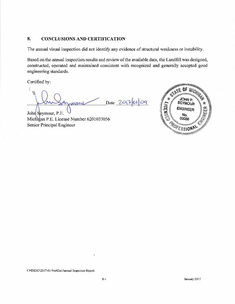
The annual visual inspection did not identify any evidence of structural weakness or instability.
The four-foot high perimeter berm and perimeter swale did not have any topsoil or vegetation. Erosion rills were identified on the outside of the western perimeter berm. However, the design approved by the MDEQ did not include a requirement to vegetate the berm and swale and the rills were minor.

CHE8242\2017-01-VertExt-Annual Inspection Report
7-3 January 2017
It is understood by Geosyntec that the existing license for the Ash Basin has a requirement to vegetate the surface of the fly ash in the Ash Basin when it reaches final grade. Further, because the vertical extension Landfill is entirely within the confinement of the Ash Basin, a soil erosion and sediment control permit is not required, implying that vegetation of the soil slopes of the perimeter berm may not be required.
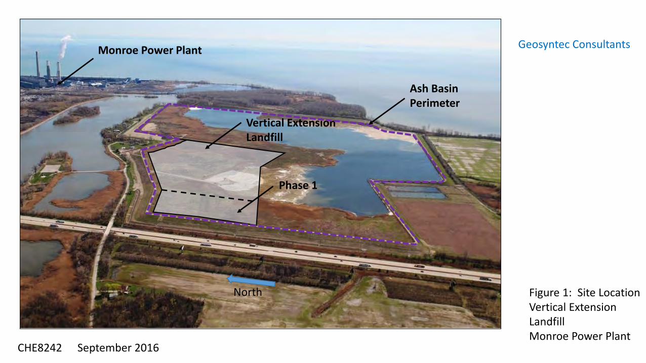
Vertical ExtensionLandfill
Phase 1
Ash Basin Perimeter
Monroe Power Plant
Figure 1: Site LocationVertical Extension LandfillMonroe Power Plant
September 2016
Geosyntec Consultants
CHE8242
North
APPENDIX ARESUME OF THE QUALIFIED PROFESSIONAL ENGINEER
JOHN SEYMOUR, P.E. coal combustion residuals management geoenvironmental engineering
geotechnical engineering
EDUCATION
M.S., Geotechnical Engineering, University of Michigan, Ann Arbor, Michigan, 1980
B.S., Civil Engineering, Michigan Technological University, Houghton, Michigan, 1976
PROFESSIONAL REGISTRATIONS
Michigan P.E. Number 620103033056
CAREER SUMMARY
Mr. Seymour is a geotechnical engineer with over three decades of experience in the areas of waste containment, site remediation, building foundations, and construction management. He has focused on solid and hazardous waste management and remediation (solid waste/RCRA and Superfund/CERCLA) projects for over 30 years. He has provided professional services in the areas of site characterization, feasibility studies, bench/pilot studies, civil/geotechnical design, construction quality assurance (CQA), disposal facility operation and maintenance, environmental permit applications, project management, project coordination (owner’s representative), and expert witness.
His focus over the past 10 years has been on coal combustion residuals management, including: facility siting studies, long term management feasibility studies, landfill design and permit applications, and pond closure design and permit applications.
He has provided coal combustion residuals (CCRs) engineering services, regarding waste management of fly ash, bottom ash and flue gas desulfurization (FGD) waste for impoundments and landfills. These services have included geotechnical and environmental evaluations of waste disposal expansions, operations and closure, disposal permit application preparation for 10 U.S coal power generation clients. Overall he has provided relevant consulting engineering services for 7 CCRs impoundments and 14 CCR landfills, and has completed research into the characteristics of all of the USEPA surface impoundments published on their website. He has visited 15 CCR landfills and 15 power plants with 29 surface impoundments. He has translated some of his experience into eight CCR related technical papers, two final guidance documents on CCR impoundments (co-investigator), and provided nine technical presentations at conferences including at conferences focusing on CCR
John Seymour, P.E. Page 2 management. He has also provided Phase 1 dam safety surveys for the U.S. Army Corps of Engineers, including site inspections for 5 dams and inspection reports for 15 dams, and dam inspections for a large power plant cooling lake.
Highlights of Mr. Seymour’s representative experience include:
Coal Combustion Residuals Project Experience
Confidential Power Generation Utility, Slope Stability Peer Review of three Surface Impoundments, Confidential Client, Midwest. He is the project director for the conduct of slope stability peer reviews at three surface impoundments.
CCR Rule Landfill and Surface Impoundment Annual Inspections, DTE Energy, Michigan. Mr. Seymour was the project manager to complete annual inspections of three CCR landfills and one surface impoundment. He was the chief inspector for one landfill and technical reviewer for the other two landfills. He was also the co-certifying engineer for the annual report for a large surface impoundment.
CCR Landfill Regrading and Closure/Post Closure Plan, Consumers Energy Company, MI. Mr. Seymour is the engineer of record and project manager to regrade portions of this existing landfill to avoid ponding of water in response to the 2015 USEPA CCR Rule. Further, he is the project manager for the closure plan, post closure plan and run-on, run-off plan required by the CCR Rule.
CCR Rule Compliance Assessments, AEP, Three Plants in Ohio and Kentucky. Mr. Seymour is the project manager to assess CCR Rule compliance for the location requirements and groundwater monitoring systems at three power plants.
Coal Combustion Residuals Rule “Templates”, Electric Power Research Institute (EPRI), Nationwide. Project Manager, co-author, and technical editor to complete guidance documents for: a) CCR Record Keeping and Website Reporting, b) development of weekly and annual inspection forms and guidance, c) training for the “qualified person” to conduct inspections, d) dust control template, and e) emergency action plan guidance and template.
Sibley Quarry Landfill Closure Options Feasibility Study, DTE Energy, Trenton, Michigan. Mr. Seymour led the effort to conduct a study of closure options under Michigan NREPA Part 115 Type III waste rules and the U.S. EPA 40 CFR 257 CCR rules. Further, he provided a CCR slope stability assessment in 2008, an assessment of CCR slope distress in 2012, and coordinated quarry wall bedrock mapping in 1996.
Closure Design Manger for two CCR Landfills, FirstEnergy, WV. Mr. Seymour was the design manager and engineer of record for the design of two CCR landfills by use of a soil cover system in 2014.
John Seymour, P.E. Page 3 Monroe Power Plant Ash Disposal Basin, DTE Energy, Monroe, MI. Mr. Seymour is the project leader for a number of projects at this 400-acre fly ash disposal basin. Recently he acted as the owner’s representative to develop a CCR landfill on top of the existing Ash Basin. Previously, he has completed or managed: (i) preliminary engineering study for future disposal, (ii) slope stability assessment and mitigation design to address slope instability, (iii) potential failure mode analysis, (iv) seepage analysis, (v) inspection, monitoring and maintenance program manual, (vi) slope stability study for a vertical expansion, (vii) reliability analysis (also called a probability of failure slope stability analysis) of 2H: 1V slopes, (viii) construction quality assurance (CQA) for a four-year slope mitigation program; and (ix) completing an Emergency Acton Plan.
Initially he managed an FGD gypsum disposal facility preliminary engineering study for new FGD gypsum waste that will be generated at a coal fired electrical generating station. Three options were evaluated: i) disposal at a “greenfield” site that has wetland impacts, ii) disposal over the top of a 400-acre ash pond, and iii) temporary disposal at an offsite coal ash landfill. Further, wet and dry handling options were evaluated.
Mr. Seymour was the project director and engineer of record to conduct an evaluation of slope stability of the side slopes of the earthen containment dike around the ash basin and to assess the potential for a failure due to operating issues. He designed and implemented an inspection program for a 3.5-mile long, 45-ft (maximum) high fly ash containment dike that lead to the development of a remedy for observed sloughing that included flattening some of the slopes, rebuilding some slopes, clearing of vegetation, and relocating a county drain (creek) under the State and U.S. Army Corps of Engineers permitting process. The work was designed to occur over four construction seasons.
In 2009 he was the project director, engineer of record and construction certifying engineer for the relocation of the county drain and temporary emergency erosion mitigation on the side slopes of the ash basin embankment to prepare the site to flatten the slopes of the ash basin embankment; construction was performed in 2010. The work included completing a Clean Water Act Section 404 (filling in waters of the U.S.) permit application, a county soil erosion and sediment control permit application for relocating the drain, slope stability analysis, regrading of the area and construction documents.
In 2010, 2011 and 2012, he was the project director, engineer of record, and construction certifying engineer for flattening of 4,000 ft of the embankment slopes including relocation of a stormwater runoff pump house.

John Seymour, P.E. Page 4 In 2013 he was the project director and construction certifying engineer for the final phase of slope mitigation that includes slope flattening and relocation of construction access ramps.
Mr. Seymour was also the project director for a study of the source of seepage observed at the toe of the embankment.
He also led the completion of a potential failure mode analysis (PFMA) for the entire ash basin disposal facility. He then assisted the owner to address high and medium priority potential failure modes that included completing a global stability assessment that utilized a reliability approach that quantified the probability of failure. He also managed the compilation of an inspection, monitoring and maintenance manual, and documented site improvements.
Coal Combustion Residuals Pond Closure Guidance Documents, Electric Power Research Institute, nationwide. Mr. Seymour is a co-investigator/author, editor and project manager for the completion of two guidance documents relating to CCR pond closures. They include: (i) “Coal Combustion Residuals Ponds- Dewatering and Capping Guidance Document”, and (ii) “Coal Combustion Residuals Pond Closure- Construction over Closed or Closing Ponds Guidance Document”. The documents address many aspects of pond closures including slope stability, safety of working on fly ash ponds, water quality discharge permitting, groundwater remediation, cover/closure design, construction of structures on top of closed ponds, hydrologic analysis, and stormwater erosion and sediment control.
J.C. Weadock CCR Landfill Engineering Study, Consumers Energy Company, Essexville, MI. Mr. Seymour was the project director and engineer of record to conduct an engineering feasibility study of the long term use and closure of a 292-acre ash pond that has been converted to dry disposal. The facility manages bottom ash and fly ash and will manage flue gas desulfurization (FGD) waste. The study is examining five options for long term disposal and closure including implementing the draft CCR rules proposed by USEPA in 2010. Mr. Seymour provided project scoping and project direction and was the engineer of record for the final submittal.
General James Gavin Power Plant Fly Ash Pond Closure Design, Cheshire, Ohio. Mr. Seymour is the project manager for the conceptual and final design of a 300-acre fly ash disposal pond closure including designing the closure in accordance with the proposed U.S. EPA RCRA Subtitle D (solid waste landfill) regulations (2010). The pond is contained by a 145-ft high earthen dam and the ponded water must be lowered in accordance with Geosyntec’s design. A conceptual design was completed followed by the final design. The conceptual design included examining several closure alternatives. The final design includes reshaping the grades of the fly ash by moving
John Seymour, P.E. Page 5 over 1,000,000 cuyd of ash and rock, lowering the dam such that no water will be retained after closure, conducting flood hydraulic and stormwater design, design of a new spillway and energy dissipater, and providing pH adjustment to treat runoff for acid mine drainage (AMD). The design includes flood studies and associated hydraulic modeling to safely pass the 100-yr, 24-hr flood event and the probable maximum flood (PMF) and meet NPDES discharge permit limits for TSS and pH. The PTI was completed under requirements of an NPDES permit modification. Construction documents were prepared and the project is in the bidding process to select a contractor.
General James Gavin Power Plant CCR Landfill Design, Cheshire, Ohio. Mr. Seymour managed the design and the Permit to Install (PTI) application for a 46,000,000 cuyd residual waste landfill for the solid waste permit application under existing OEPA rules and incorporated relevant portions of the U.S. EPA proposed (2010) RCRA Subtitle D regulations. An engineering feasibility study was first completed to select either a Greenfield site or a site that included a lateral expansion over an adjacent fly ash pond and vertically over the existing landfill. The lateral expansion over the fly ash pond was selected. The work to complete the PTI included: a comprehensive geotechnical and hydrogeological investigation, geophysical investigation to locate underground mines, assessment of strength of all geologic and waste materials, slope stability, settlement analysis, liquefaction analysis of the ponded fly ash in the subgrade, leachate system collection and treatment design, surface water hydraulic analyses and leachate pond design for the 25-year, 24-hour storm event, preparation of a site investigation report, preparation of a hydrogeologic study report, preparation of a settlement and stability analysis report, construction and operations information report, final closure and post closure plan, groundwater monitoring plan, the quality assurance/quality control plan including specifications and the PTI application report. The PTI application was submitted in August 2011 and included four volumes and 67 design drawings and the OEPA provided a verbal approval in October 2012. He managed the completion of construction and bid documents. The initial phase of the expansion is currently under construction.
R. Paul Smith CCB Landfill Expansion and Ash Pond Cleanout, Allegheny Energy Supply, Berkeley County, WV. Mr. Seymour was the project manager and engineer of record for the design and construction quality assurance of a coal combustion byproducts landfill for a coal-fired power plant that is located in Maryland with the landfill located in adjacent West Virginia. He led the completion of an evaluation of the most economical landfill expansion approach, which considered vertical and lateral expansion options. The selected method of expansion included three elements: lateral expansion using a composite liner system, vertical expansion using a mechanically
John Seymour, P.E. Page 6 stabilized earth (MSE) retention system, and a vertical expansion over the top of the existing disposal area.
He managed the design of the landfill for the solid waste permit application and construction bid package that included the design for the cleanout of Ash Pond 3. He then managed the construction quality assurance (CQA) for the construction of the Phase A portion and prepared the construction certification report obtaining approval of WVDEP of each layer (subgrade, groundwater underdrain, liner, and leachate collection layer) within 5 days of submittal of completion documentation. He most recently was the project director and engineer of record for the permit renewal application.
Cardinal Plant CCR Landfill Studies, American Electric Power, Brilliant, Ohio. He completed a feasibility study to assess the potential to develop a new FGD waste landfill over an existing fly ash disposal impoundment at a coal-fired power plant. The feasibility study included utilization of mine spoil as a building product for low permeability liners, examination of foundation settlement and liquefaction potential for this landfill that was to be located over 170 ft thick (maximum) layer of saturated coal ash in a “cross valley fill” that was contained by an earthen dam approximately 150-ft high.
Lake Lansing Road Fly Ash Landfill Hydrogeological Investigation, Lansing Board of Water & Light, Lansing, Michigan. As Project Director, he developed a strategy to address MDEQ comments on previous groundwater contamination studies. The strategy included fully addressing the new state regulations for groundwater monitoring at this fly ash disposal facility. He then led the team to design the work plan and implement the investigation.
Litigation Assignments
Mr. Seymour has been an expert witness services for ten matters. He has prepared expert reports, been deposed, and provided testimony at trial. The following summarizes his experience.
Confidential Client, 2014. Mr. Seymour has been retained as an expert in the field of groundwater remediation at and around CCR treatment ponds at four coal fueled power plants.
Confidential Client, 2014. Mr. Seymour was retained as an expert in the field of CCR landfill design constructed over a closed coal ash pond (“overfill”). His work was to provide a response to comments that were in opposition to the proposed landfill.
Kingston Dredge Cell Failure Insurance Arbitration, Tennessee Valley Authority, 2013. Mr. Seymour was retained as an expert in the field of CCR ponds for the arbitration of the denial of a major insurance claim. He represented the plaintiff who
John Seymour, P.E. Page 7 was denied insurance coverage for the failure of a CCR facility. He prepared the expert witness report which included research into all of the CCR ponds that were inspected by USEPA from 2009 to 2012. The research was utilized to successfully obtain full relief.
Confidential Landfill Remedial Action Litigation Support Services, Republic Services, north-central IL. Provided technical support to legal counsel for the remedy selection process at a 40-acre solid waste facility closed in the 1970s and developed into a park.
AmForge Site Expert Witness Engineering, Arvin-Meritor, Chicago, IL, 2006. Provided engineering support in the areas of contaminant fate and transport, risk assessment, and site characterization for expert witness services in this cost recovery case. The cost recovery was undertaken by private parties brought under CERCLA. The AmForge Site is a former foundry that was sold in the early 1980s. It was later acquired and remediated and the plaintiff is seeking cost recovery from our client for contamination related to the former foundry.
Yeoman Creek Landfill Superfund Site PRP Contribution Litigation, Illinois 2004-2005. Mr. Seymour was hired as the expert for a PRP Group suing a party for contribution for remediation of a CERCL site in Illinois. He provided expert testimony under deposition.
CCP v. Kent County, Michigan, Kent County Aeronautics Board, Grand Rapids, MI, 1996. Mr. Seymour was retained as the expert for the defendant who was being sued for $15,000,000 in damages after the taking of a former hazardous waste treatment, storage and disposal property owned by the plaintiff for the expansion of an airport. He prepared the expert report, depositions and testimony at trial. The client was found to be not liable for all but approximately $200,000 in damages, and the client considered this a very favorable result.
City of Howell, Michigan v. VCF Films, 1994. Mr. Seymour assisted in an arbitration case on behalf of the City of Howell, Michigan in pursuit of cost contribution to remediate a closed municipal waste facility. He provided an expert report regarding the allocation of cost to address a specific compound found in groundwater at the facility from the defendant’s manufacturing process. The arbitration was considered successful by the client.
Carter Lumber V. LTV Steel, Lancaster, Ohio, 1995. Provided expert witness services for the defendant in the area of contamination site assessment in this cost recovery case litigated under CERCLA. The former lumber site was previously used to store wastes, in particular, PCB transformers. The plaintiff sought relief for remediation of the PCBs. He provided an expert witness report. The case was favorably settled.
John Seymour, P.E. Page 8
PROFESSIONAL EXPERIENCE
Geosyntec Consultants, Chicago, IL, 2001–present URS Corporation, Detroit, MI, 1997–2001 Woodward-Clyde Consultants (later URS), Chicago, IL and Detroit, MI, 1980-1997 Townsend and Bottum, Ann Arbor, MI, 1978-1979 Stone & Webster, Shippingport, PA, 1976-1978
AFFILIATIONS
American Society of Civil Engineers
Midwest Coal Ash Association
Society of American Military Engineer
REPRESENTATIVE PUBLICATIONS
15-08 “EPA’s Coal Combustion Residuals Rule: Review of Applicability, Exemptions, and Technical Requirements”, American Bar Association Section of Environment, Energy, and Resources, Vol. 15, No. 1, August 2015, Mike Houlihan, John Seymour, and Steven Burns.
15-05 “Geotechnical Considerations for Surface Impoundment Closure to Meet the CCR Rule & Avoid Compliance and Constructability Pitfalls”, Technical Short Course Instructor at the World of Coal Ash conference, Nashville, TN.
15-05- “Reliability Analysis of an Existing Ash Basin Embankment”, World of Coal Ash Conference, Nashville, TN, May 2015, Omer Bozok, Burak F. Tanyu, Paul Sabatini, John Seymour.
15-01 “Conditions of Coal Ash Embankments”, at the U.S. Society on Dams Conference, April 2015 I Louisville, KY, John Seymour, P.E., Omer Bozok, Amanda Hughes, Ph.D., Brad Bodine, P.E.
14-05 “Coal Combustion Residuals Pond Closure, Guidance for Dewatering and Capping”, EPRI Technical Report 3002001117, Palo Alto, CA, J. Seymour, W. Steier, C Li, P Sabatini, M Lodato, M. Bardol, M. Gross.
14-05 “Coal Combustion Residuals Pond Closure, Guidance for Construction Over Closed or Closing Ponds”, EPRI Technical Report 3002001143, Palo Alto, CA, P. Sabatini, R. Kulasingam, J. Seymour,
13-04 “Challenges of Closing Large Fly Ash Ponds”, at the World of Coal Ash Conference, Lexington, Kentucky, April 2013. Lead author and presenter.
John Seymour, P.E. Page 9 11-05 “Advances in Design of Landfills over CCR Ponds and CCR Landfills”,
Proceedings from the World of Coal Ash conference, Denver, CO, John Seymour, P.E. and Michael F. Houlihan, P.E. BCEE, May 2011. Lead author and presenter.
INVITED PRESENTATIONS
He has presented the following papers or provided these presentations:
16-11 “Geotechnical Considerations in Surface Impoundment Management and Closure”, Teaching Position for the American Coal Ash Association/University of Kentucky Center for Applied Energy Research/Electric Power Research Institute Workshop on Current Issues in Ponded Ash, Fall Meeting, Covington, KY.
16-02 “Slope Stability Considerations under the New CCR Rule”, Utility Solid Waste Activities Group Workshop, Washington, D.C.
16-02 “Structural Integrity Considerations under the CCR Rule”, Teaching Position for the American Coal Ash Association/University of Kentucky Center for Applied Energy Research/Electric Power Research Institute Workshop on Current Issues in Ponded Ash, Winter Meeting, Tampa, FL.
15-10 “Response to the New Coal Combustion Residuals (CCR) Rule”, to the American Bar Association Energy, Environment and Resources Annual Meeting, Chicago, IL.
15-06 “Slope Stability Considerations under the CCR Rule” and “Inspections and Monitoring of CCR Surface Impoundments”, to the Electric Power Research Institute Program 49 Companies, Bar Harbor, ME.
15-05 “Geotechnical Considerations for Surface Impoundment Closure to Meet the CCR Rule & Avoid Compliance and Constructability Pitfalls”, Technical Short Course Teacher at the World of Coal Ash conference, Nashville, TN.
15-04 “Conditions of Coal Ash Embankments”, at the U.S. Society on Dams Conference, April 2015 I Louisville, KY, John Seymour, P.E., Omer Bozok, Amanda Hughes, Ph.D., Brad Bodine, P.E.
14-03 “CCB Wet Pond Assessment, Closure, and Redevelopment”, presentation provided to FirstEnergy, March, 2014.
13-12 “CCR Pond Closures: Major Difficulties and Solutions”, presentation to the Utility Solid Waste Activities Group, Washington, D.C., December, 2013.
13-11 “CCR Pond Closures: Major Difficulties and Solutions”, presentation and workshop for the Tennessee Valley Authority, Chattanooga, Tennessee, November 2013.

John Seymour, P.E. Page 10 13-04 “Challenges of Closing Large Fly Ash Ponds”, at the World of Coal Ash
Conference, Lexington, Kentucky, April 2013.
13-04 “Hot Topics Regarding Coal Combustion Residuals Management, presentation to Winston & Strawn Environmental Group, Chicago, Illinois, April 2013.
12- 08 “Landfills over CCR Ponds”, Webinar with CETCO serving over 140 participants, August 2012, repeated in September 2012.
11-05 Presentation of: “Advances in Design of Landfills over CCR Ponds and CCR Landfills”, at the World of Coal Ash conference, Denver, CO, May 2011.
09-04 “Geotechnical Design Considerations for Landfill Construction Over an Ash Pond”, World of Coal Ash, Lexington, KY, May 2009
APPENDIX B2016 LANDFILL VISUAL INSPECTION
CHECKLIST AND PHOTOGRAPHS
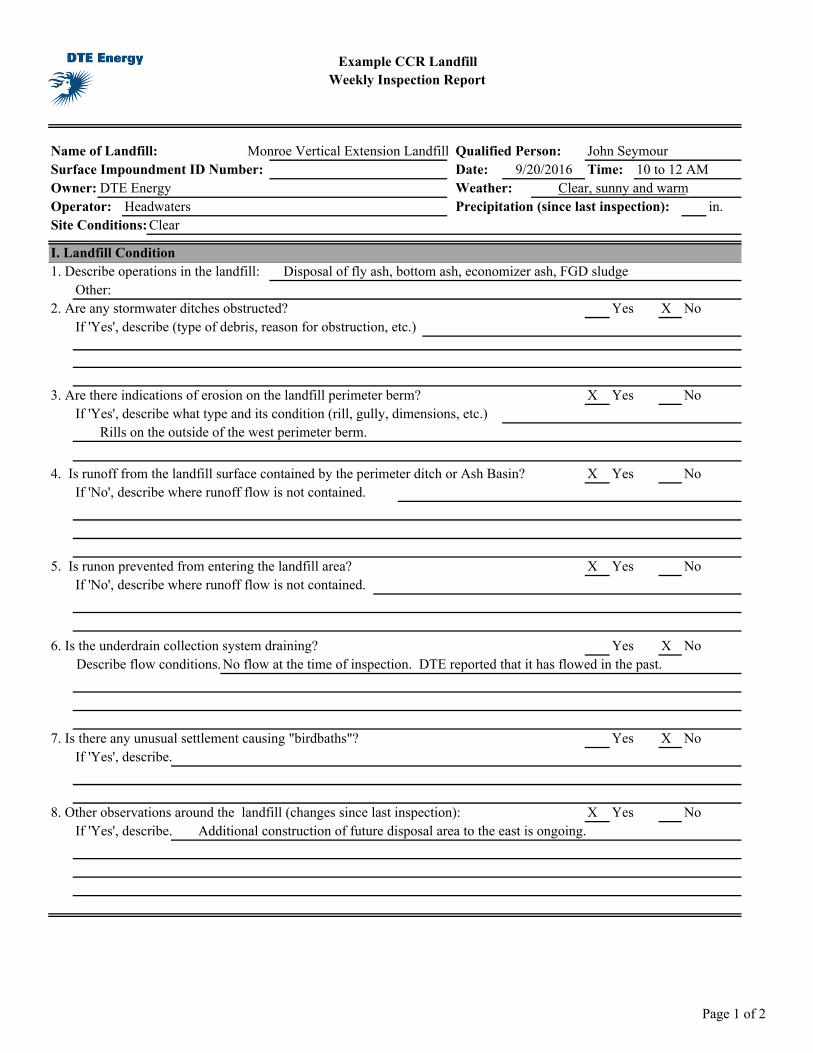
Example CCR LandfillWeekly Inspection Report
Name of Landfill: Qualified Person: John SeymourSurface Impoundment ID Number: Date: 10 to 12 AMOwner: DTE Energy Weather: Clear, sunny and warmOperator: Headwaters Precipitation (since last inspection): in.Site Conditions: Clear
I. Landfill Condition1. Describe operations in the landfill:
Other: Yes X No
If 'Yes', describe (type of debris, reason for obstruction, etc.)
X Yes NoIf 'Yes', describe what type and its condition (rill, gully, dimensions, etc.)
Rills on the outside of the west perimeter berm.
4. Is runoff from the landfill surface contained by the perimeter ditch or Ash Basin? X Yes No
X Yes NoIf 'No', describe where runoff flow is not contained.
6. Is the underdrain collection system draining? Yes X NoNo flow at the time of inspection. DTE reported that it has flowed in the past.
Yes X NoIf 'Yes', describe.
8. Other observations around the landfill (changes since last inspection): X Yes NoIf 'Yes', describe. Additional construction of future disposal area to the east is ongoing.
Monroe Vertical Extension LandfillTime:
Disposal of fly ash, bottom ash, economizer ash, FGD sludge
2. Are any stormwater ditches obstructed?
3. Are there indications of erosion on the landfill perimeter berm?
5. Is runon prevented from entering the landfill area?
Describe flow conditions.
7. Is there any unusual settlement causing "birdbaths"?
If 'No', describe where runoff flow is not contained.
9/20/2016
Page 1 of 2
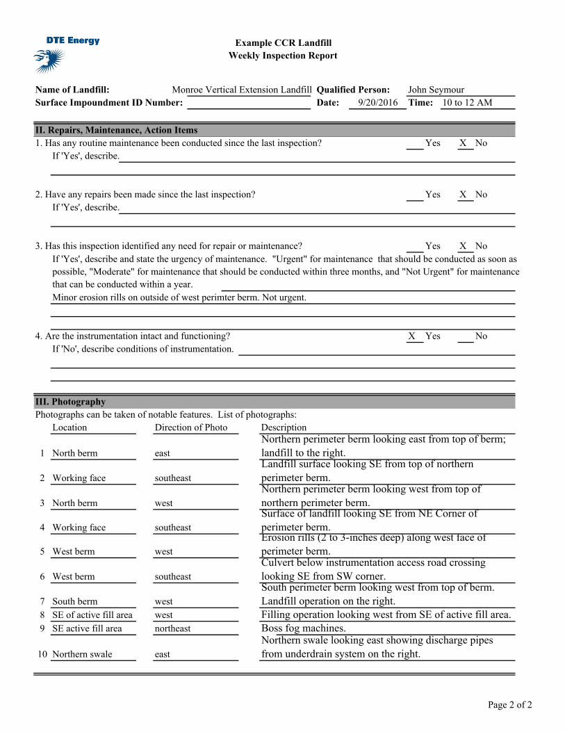
Example CCR LandfillWeekly Inspection Report
Name of Landfill: Qualified Person: John SeymourSurface Impoundment ID Number: Date: 10 to 12 AM
Monroe Vertical Extension LandfillTime:9/20/2016
II. Repairs, Maintenance, Action Items1. Has any routine maintenance been conducted since the last inspection? Yes X No
If 'Yes', describe.
2. Have any repairs been made since the last inspection? Yes X NoIf 'Yes', describe.
3. Has this inspection identified any need for repair or maintenance? Yes X No
Minor erosion rills on outside of west perimter berm. Not urgent.
4. Are the instrumentation intact and functioning? X Yes NoIf 'No', describe conditions of instrumentation.
III. Photography
Location Direction of Photo Description
1 North berm east
2 Working face southeast
3 North berm west
4 Working face southeast
5 West berm west
6 West berm southeast
7 South berm west8 SE of active fill area west9 SE active fill area northeast Boss fog machines.
10 Northern swale east
Culvert below instrumentation access road crossing looking SE from SW corner.South perimeter berm looking west from top of berm. Landfill operation on the right.Filling operation looking west from SE of active fill area.
Northern swale looking east showing discharge pipes from underdrain system on the right.
Northern perimeter berm looking east from top of berm; landfill to the right.Landfill surface looking SE from top of northern perimeter berm.Northern perimeter berm looking west from top of northern perimeter berm.Surface of landfill looking SE from NE Corner of perimeter berm.Erosion rills (2 to 3-inches deep) along west face of perimeter berm.
Photographs can be taken of notable features. List of photographs:
If 'Yes', describe and state the urgency of maintenance. "Urgent" for maintenance that should be conducted as soon as possible, "Moderate" for maintenance that should be conducted within three months, and "Not Urgent" for maintenance that can be conducted within a year.
Page 2 of 2
1
DTE ENERGY Photographic Record
Client: DTE Electric Company Project Number: CHE8242H9
Site Name: Monroe Ash Basin Vertical Extension Landfill Site Location: Monroe, MI
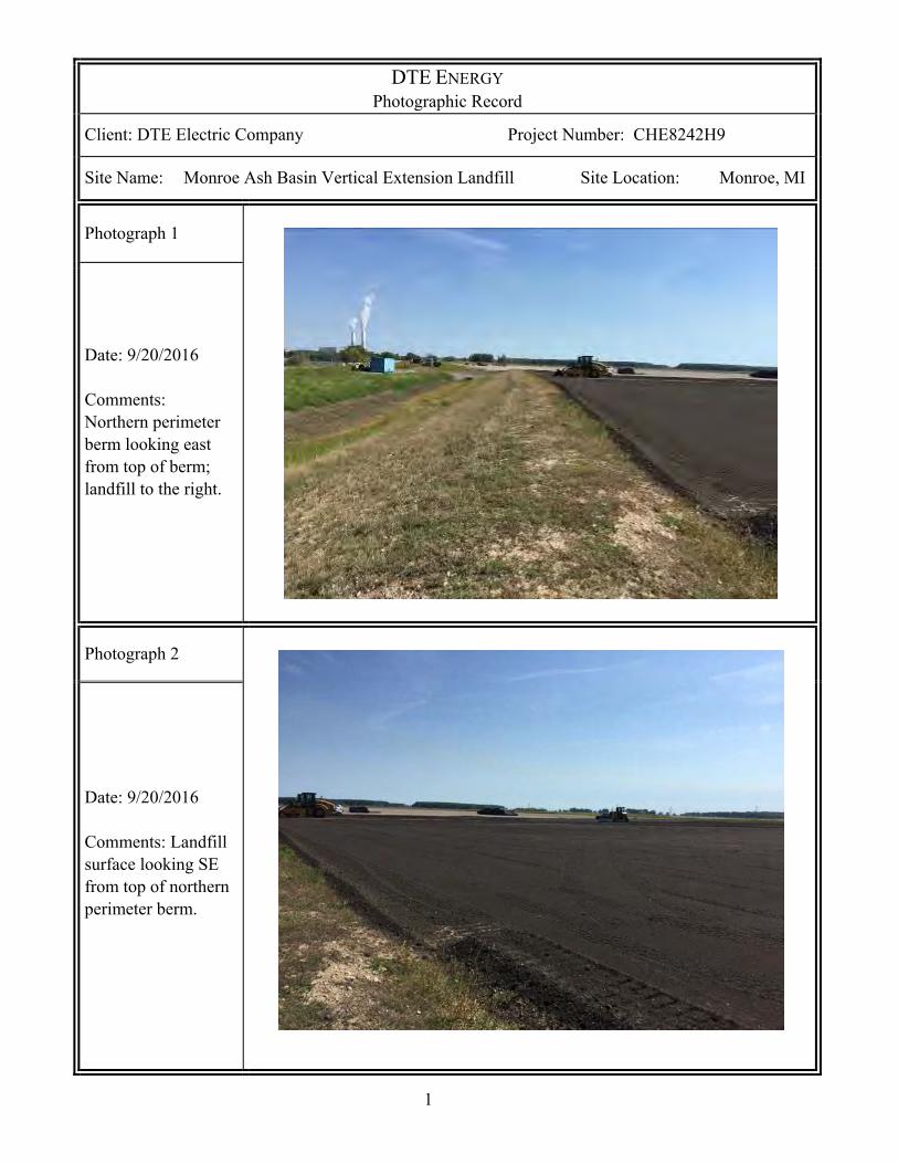
Photograph 1
Date: 9/20/2016 Comments: Northern perimeter berm looking east from top of berm; landfill to the right.
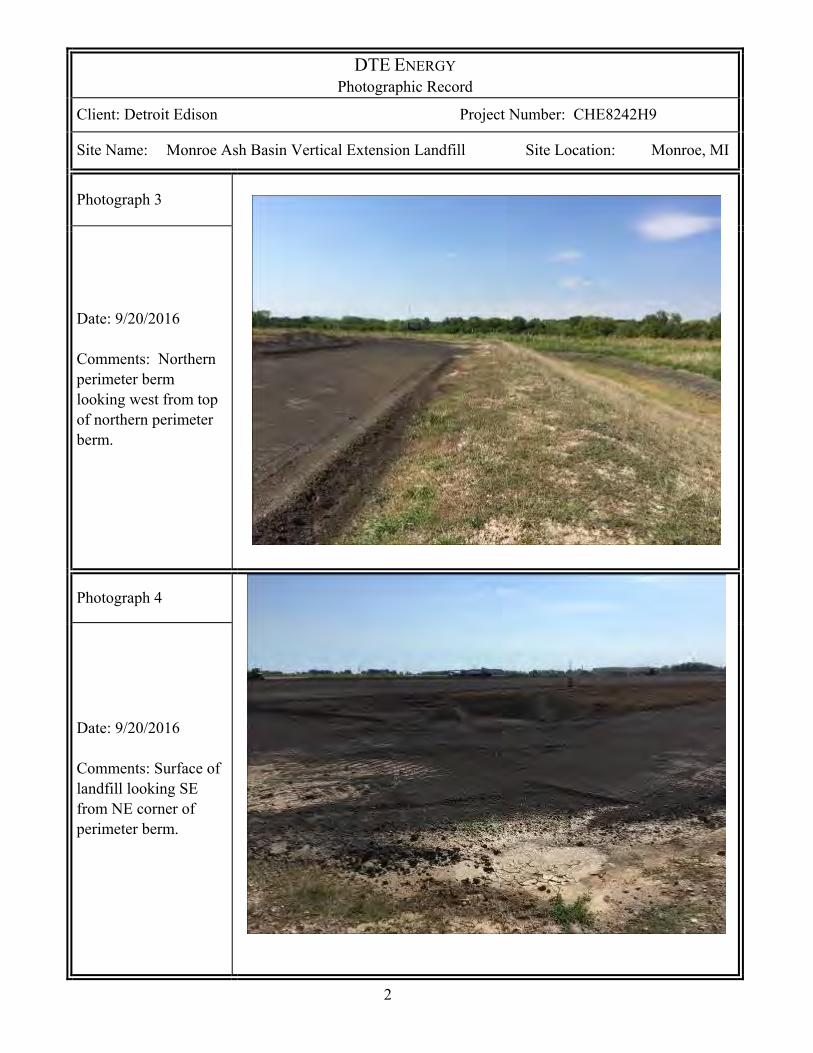
Photograph 2
Date: 9/20/2016 Comments: Landfill surface looking SE from top of northern perimeter berm.
2
DTE ENERGY Photographic Record
Client: Detroit Edison Project Number: CHE8242H9
Site Name: Monroe Ash Basin Vertical Extension Landfill Site Location: Monroe, MI
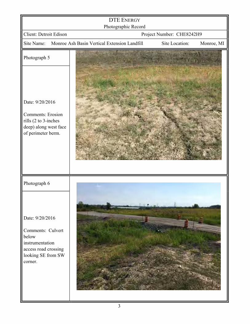
Photograph 3
Date: 9/20/2016 Comments: Northern perimeter berm looking west from top of northern perimeter berm.
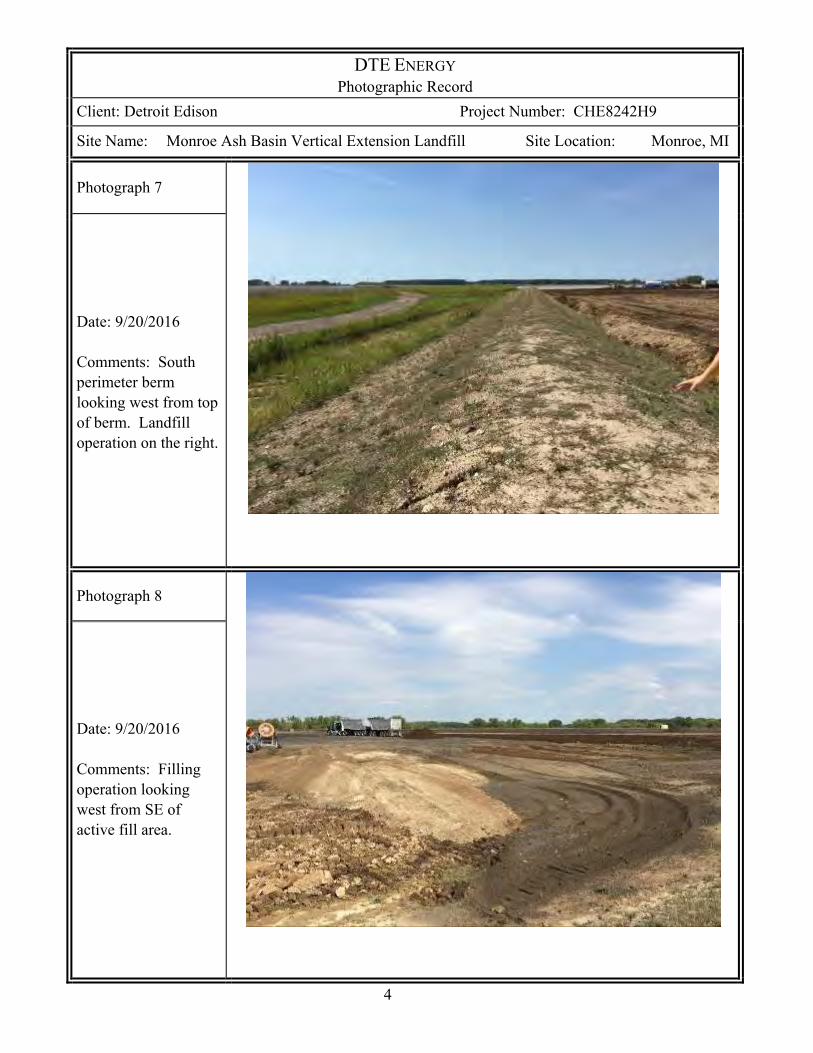
Photograph 4
Date: 9/20/2016 Comments: Surface of landfill looking SE from NE corner of perimeter berm.
3
DTE ENERGY Photographic Record
Client: Detroit Edison Project Number: CHE8242H9
Site Name: Monroe Ash Basin Vertical Extension Landfill Site Location: Monroe, MI
Photograph 5
Date: 9/20/2016 Comments: Erosion rills (2 to 3-inches deep) along west face of perimeter berm.
Photograph 6
Date: 9/20/2016 Comments: Culvert below instrumentation access road crossing looking SE from SW corner.
4
DTE ENERGY Photographic Record
Client: Detroit Edison Project Number: CHE8242H9
Site Name: Monroe Ash Basin Vertical Extension Landfill Site Location: Monroe, MI
Photograph 7
Date: 9/20/2016 Comments: South perimeter berm looking west from top of berm. Landfill operation on the right.
Photograph 8
Date: 9/20/2016 Comments: Filling operation looking west from SE of active fill area.
5
DTE ENERGY Photographic Record
Client: Detroit Edison Project Number: CHE8242H9
Site Name: Monroe Ash Basin Vertical Extension Landfill Site Location: Monroe, MI
Photograph 9
Date: 9/20/2016 Comments: Boss fog machines.
Photograph 10
Date: 9/20/2016 Comments: Northern swale looking east showing discharge pipes from underdrain system on the right.

APPENDIX CINSTRUMENTATION LOCATIONS

O/H O/H O/H O/HO/H
O/HO/H
O/HO/H O/H O/H O/H O/H O/H O/H O/H O/H O/H O/H O/H
O/HO/H
O/HO/H
O/HO/H
O/HO/H
O/HO/H
O/H
O/H
O/H
O/H
0.50
%
TITLE
PROJECT No. Rev.
PROJECTCLIENT
Path
: \\la
n1-v
-fs1\
cad\
Proj
ects
\15x
-Pro
ject
s\15
2180
9B_D
TE M
onro
e\PR
OD
UC
TIO
N\D
-As
Built
Dra
win
gs\
| Fi
le N
ame:
152
1809
B_D
-6.d
wg
IF T
HIS
MEA
SUR
EMEN
T D
OES
NO
T M
ATC
H W
HAT
IS S
HO
WN
, TH
E SH
EET
SIZE
HAS
BEE
N M
OD
IFIE
D F
RO
M: A
NSI
D0
1 in
DESIGN
PREPARED
REVIEW
APPROVED
YYYY-MM-DDCONSULTANT
1521809BCONTROL
FIGURE
8
2015-09-10
JJS
JJS
JJS
DML
MONROE POWER PLANT ASH BASIN2015 PHASE 1 RECORD DRAWINGS
DTE ENERGYMONROE POWER PLANTMONROE, MI
RECORD MONITORING LOCATIONS FOR PHASE 1
0
FEET
120 240
SCALE
CONSTRUCT PHASE 1
LEGEND
SLOPE INCLINOMETER
VIBRATING WIRE PIEZOMETER (VWP) PAIR (DEEP & SHALLOW)
SETTLEMENT PLATE
REMOTE (CABLED) DATA LOGGER LOCATION FOR VWP
DATA LOGGER CABLE
SI-1
PZ-1DPZ-1S
SP-1
RECORD DRAWING
RECORD INSTRUMENTATION INFORMATION
INSTRUMENTIDENTIFICATION NORTHING EASTING ELEVATION
PZ-1S PZ-1D 143,132.58 13,391,553.77 614.71
PZ-2S PZ-2D 142,791.36 13,391,744.99 615.92
PZ-3S PZ-3D 142,601.23 13,391,236.06 614.26
SI-10 142,280.24 13,391,364.86 612.45
SI-9 142,989.72 13,391,192.71 611.28
SP-3 143,124.35 13,391,551.76 615.34
SP-4 142,779.81 13,391,741.28 616.31
SP-5 142,591.55 13,391,231.59 614.76
APPENDIX D OPERATIONAL INFORMATION
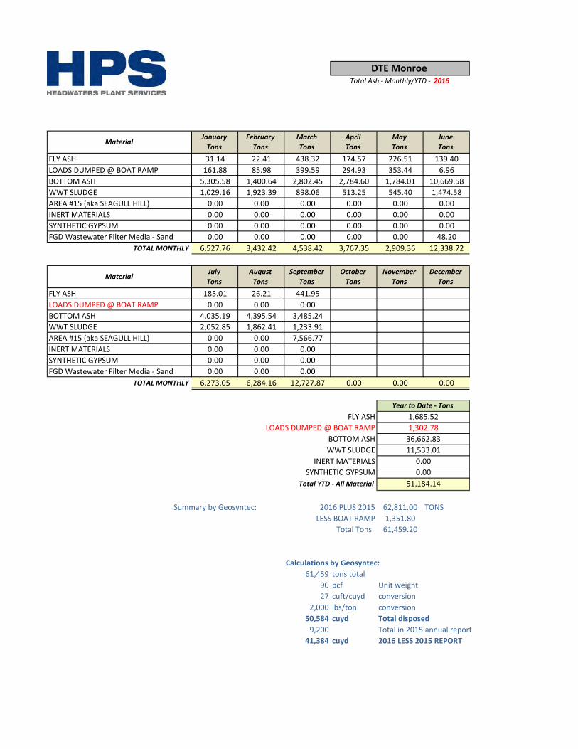
FLY ASH 31.14 22.41 438.32 174.57 226.51 139.40LOADS DUMPED @ BOAT RAMP 161.88 85.98 399.59 294.93 353.44 6.96BOTTOM ASH 5,305.58 1,400.64 2,802.45 2,784.60 1,784.01 10,669.58WWT SLUDGE 1,029.16 1,923.39 898.06 513.25 545.40 1,474.58AREA #15 (aka SEAGULL HILL) 0.00 0.00 0.00 0.00 0.00 0.00INERT MATERIALS 0.00 0.00 0.00 0.00 0.00 0.00SYNTHETIC GYPSUM 0.00 0.00 0.00 0.00 0.00 0.00FGD Wastewater Filter Media - Sand 0.00 0.00 0.00 0.00 0.00 48.20
TOTAL MONTHLY 6,527.76 3,432.42 4,538.42 3,767.35 2,909.36 12,338.72
FLY ASH 185.01 26.21 441.95LOADS DUMPED @ BOAT RAMP 0.00 0.00 0.00BOTTOM ASH 4,035.19 4,395.54 3,485.24WWT SLUDGE 2,052.85 1,862.41 1,233.91AREA #15 (aka SEAGULL HILL) 0.00 0.00 7,566.77INERT MATERIALS 0.00 0.00 0.00SYNTHETIC GYPSUM 0.00 0.00 0.00FGD Wastewater Filter Media - Sand 0.00 0.00 0.00
TOTAL MONTHLY 6,273.05 6,284.16 12,727.87 0.00 0.00 0.00
Summary by Geosyntec: 2016 PLUS 2015 62,811.00 TONSLESS BOAT RAMP 1,351.80
Total Tons 61,459.20
Calculations by Geosyntec:61,459 tons total
90 pcf Unit weight27 cuft/cuyd conversion
2,000 lbs/ton conversion50,584 cuyd Total disposed
9,200 Total in 2015 annual report41,384 cuyd 2016 LESS 2015 REPORT
11,533.01
51,184.14
0.000.00
FLY ASHLOADS DUMPED @ BOAT RAMP
Total YTD - All MaterialSYNTHETIC GYPSUM
INERT MATERIALSWWT SLUDGEBOTTOM ASH
DecemberTons
Year to Date - Tons1,685.52
36,662.83
NovemberTons
1,302.78
MaterialJulyTons
AugustTons
SeptemberTons
OctoberTons
DTE Monroe Total Ash - Monthly/YTD - 2016
Material JanuaryTons
FebruaryTons
MarchTons
AprilTons
MayTons
JuneTons
FLY ASHLOADS DUMPED @ BOAT RAMPBOTTOM ASHWWT SLUDGEINERT MATERIALSSYNTHETIC GYPSUM
TOTAL MONTHLY
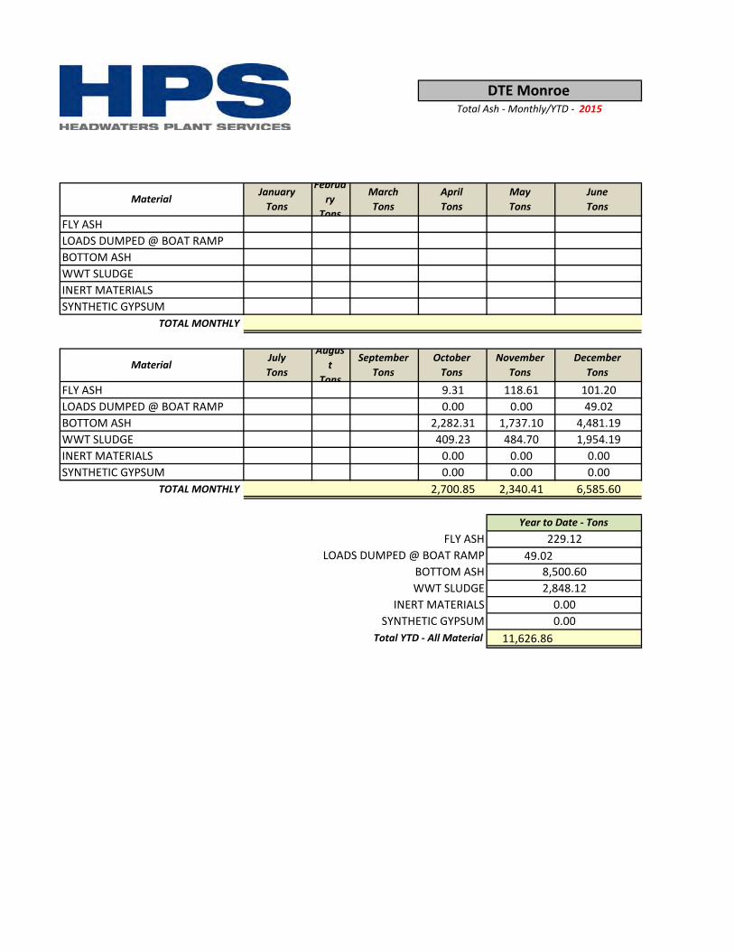
FLY ASH 9.31 118.61 101.20LOADS DUMPED @ BOAT RAMP 0.00 0.00 49.02BOTTOM ASH 2,282.31 1,737.10 4,481.19WWT SLUDGE 409.23 484.70 1,954.19INERT MATERIALS 0.00 0.00 0.00SYNTHETIC GYPSUM 0.00 0.00 0.00
TOTAL MONTHLY 2,700.85 2,340.41 6,585.60
49.02
11,626.860.000.00
229.12
8,500.602,848.12
FLY ASH
Total YTD - All MaterialSYNTHETIC GYPSUM
INERT MATERIALSWWT SLUDGEBOTTOM ASH
LOADS DUMPED @ BOAT RAMP
Year to Date - Tons
JulyTons
August
Tons
SeptemberTons
OctoberTons
NovemberTons
DecemberTons
JuneTons
DTE Monroe Total Ash - Monthly/YTD - 2015
Material
MaterialJanuary
Tons
February
Tons
MarchTons
AprilTons
MayTons