monroe vertical extension 2018 annual inspection report
TRANSCRIPT

``````````````````````````````````````````
``````````````````````````````````````````
Prepared for
DTE Electric Company One Energy Plaza
Detroit, Michigan 48226
2018 ANNUAL INSPECTION REPORT VERTICAL EXTENSION LANDFILL
MONROE POWER PLANT
Monroe, Michigan
Prepared by
3520 Green Court, Suite 275 Ann Arbor, Michigan 48105
CHE8242V-02
January 2019

CHE8242\Monroe Vertical Extension 2018 Annual Inspection Report - FINAL
i January 2019
TABLE OF CONTENTS
1. INTRODUCTION ................................................................................................................ 1-1
1.1 Overview ....................................................................................................................... 1-1
1.2 Purpose .......................................................................................................................... 1-1
1.3 Report Organization ...................................................................................................... 1-2
1.4 Terms of Reference ....................................................................................................... 1-2
2. REVIEW OF AVAILABLE INFORMATION ................................................................... 2-1
3. FACILITY DESCRIPTION ................................................................................................. 3-1
3.1 Overall Site Description ................................................................................................ 3-1
3.2 Design............................................................................................................................ 3-1
3.3 Construction .................................................................................................................. 3-3
4. VISUAL INSPECTION RESULTS ..................................................................................... 4-1
5. INSTRUMENTATION MONITORING ............................................................................. 5-1
5.1 Slope Inclinometers ....................................................................................................... 5-1
5.2 Piezometers ................................................................................................................... 5-1
5.3 Settlement Plates ........................................................................................................... 5-1
6. OPERATION ACTIVITIES ................................................................................................ 6-1
6.1 Operations Organization ............................................................................................... 6-1
6.2 Operation Activities ...................................................................................................... 6-1
6.3 Run-On/Run-Off Control System Plan for CCR Disposal Facility Observations ........ 6-2

CHE8242\Monroe Vertical Extension 2018 Annual Inspection Report - FINAL
ii January 2019
7. EVALUATION .................................................................................................................... 7-1
7.1 Design............................................................................................................................ 7-1
7.2 Construction .................................................................................................................. 7-1
7.3 Maintenance .................................................................................................................. 7-1
7.4 Operations ..................................................................................................................... 7-1
7.4.1 Operations Plan .................................................................................................. 7-1
7.4.2 Fugitive Dust Control Plan ................................................................................. 7-1
7.4.3 Run on and Run off Control ............................................................................... 7-2
7.4.4 Inspections .......................................................................................................... 7-2
7.4.5 Monitoring .......................................................................................................... 7-2
7.4.6 Annual Visual Inspection ................................................................................... 7-2
8. CONCLUSIONS AND CERTIFICATION ......................................................................... 8-1
LIST OF TABLES
Table 1: Available Information Reviewed for Annual Inspection
LIST OF FIGURES
Figure 1: Site Location
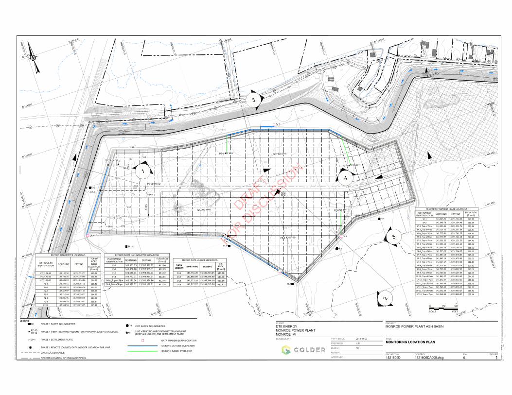
Figure 2: Landfill Instrumentation Layout
LIST OF APPENDICES
Appendix A Resume of Omer Bozok, P.E. (Qualified Professional Engineer)
Appendix B 2018 Landfill Visual Inspection Checklist and Photographs

CHE8242\Monroe Vertical Extension 2018 Annual Inspection Report - FINAL
1-1 January 2019
1. INTRODUCTION
1.1 Overview
This 2018 Annual Inspection Report (AIR) was prepared by Geosyntec Consultants (Geosyntec) to provide the results of the annual inspection of the coal combustion residuals (CCR) vertical extension landfill (Landfill) at the DTE Electric Company (DTE) Monroe Power Plant disposal facility. The annual inspection has been prepared to comply with United States Environmental Protection Agency (USEPA) Coal Combustion Residuals Rule (CCR Rule) published on April 17, 2015 (40 CFR 257.84). Under the CCR Rule, the Landfill is an “existing landfill” per 40 CFR 257.53 and must be inspected by a qualified professional engineer on a periodic basis, not to exceed one year.
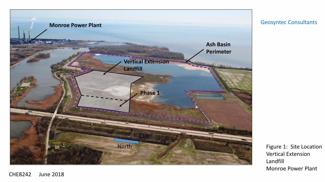
The Landfill is located about one mile southwest of the Monroe Power Plant near Monroe, Michigan, and is bounded on the east by Lake Erie and the Plant discharge canal, on the west by Interstate Highway 75 (I-75), on the south by an agricultural field, and on the north by residential property and Plum Creek (see Figure 1). It is constructed on top of fly ash that was previously deposited in the Monroe Ash Basin (Ash Basin). The combined Landfill and Ash Basin is considered the “Permitted Area”.
Landfill Phase 1 construction began in August 2015, the Michigan Department of Environmental Quality (MDEQ) licensed the area for disposal via email communication on October 14, 2015, and CCR was placed in the unit beginning October 16, 2015. CCR disposal continued after 19 October 20151 as witnessed during subsequent annual inspections. Landfill construction was completed in 2017 and the certification report was submitted to the Michigan Department of Environmental Quality (MDEQ) for approval for CCR disposal.
1.2 Purpose
The purpose of the inspection under the CCR Rule [40 CFR 257.84(b)(1)] is:
“…to ensure that the design, construction, operation, and maintenance of the CCR unit is consistent with recognized and generally accepted good engineering standards. The inspection must, at a minimum, include:
1 Based on the CCR Rule, existing landfill is “…landfill that receives CCR both before and after October 19, 2015, or for which construction commenced prior to October 19, 2015 and receives CCR on or after October 19, 2015…”.

CHE8242\Monroe Vertical Extension 2018 Annual Inspection Report - FINAL
1-2 January 2019
(i) A review of available information regarding the status and condition of the CCR unit, including, but not limited to, files available in the operating record (e.g., the results of inspection by a qualified person, and results of previous annual inspections); and
(ii) A visual inspection of the CCR unit to identify signs of distress or malfunction of the CCR unit.”
The purpose is accomplished through periodic visual inspection (and photo-documentation) of the Landfill, review of instrumentation monitoring data and evaluations intended to detect signs of instability, and review of construction certification documentation, and review of operating records since the 2016 annual inspection.
1.3 Report Organization
The remainder of this report is organized as follows:
Section 2 – Review of available information: summarizes various historical documents that were reviewed as part of this inspection
Section 3 – Facility Description: provides information about the facility
Section 4 – Visual Inspection Results: summarizes visual observations recorded during inspections of the Landfill
Section 5 – Instrumentation Monitoring: provides information about the instrumentation monitoring
Section 6 – Operation Activities: describes the operations organization and activities
Section 7 – Evaluation: evaluates the results of the annual inspection
Section 8 – Conclusions and Certification: provides the overall conclusions of the annual inspection
1.4 Terms of Reference
The annual visual inspection was performed by Mr. Omer Bozok, P.E. and Mr. David Kein, E.I.T. of Geosyntec. Mr. Omer Bozok, P.E. is the qualified professional engineer under the CCR Rule. His resume is provided in Appendix A. DTE’s “qualified person”, who conducts the weekly inspections, accompanied Mr. Bozok and Mr. Kein.

CHE8242\Monroe Vertical Extension 2018 Annual Inspection Report - FINAL
1-3 January 2019
This report was prepared by Mr. Omer Bozok, P.E. of Geosyntec. The peer review was completed by Mr. Daniel Bodine, P.E. of Geosyntec and senior review was conducted by Mr. John Seymour, P. E. of Geosyntec. John Seymour, P.E. and Daniel Bodine, P.E. of Geosyntec are qualified professional engineers per the requirements of §257.53 of the CCR Rule. Both engineers have been heavily involved with the Site since 2009, the initiation of the design and construction efforts for the mitigation of the ash basin embankment.

CHE8242\Monroe Vertical Extension 2018 Annual Inspection Report - FINAL
2-1 January 2019
2. REVIEW OF AVAILABLE INFORMATION
Geosyntec reviewed the following documents for the annual inspection. These documents are summarized in the table below.
Table 1: Available Information Reviewed for Annual Inspection
Title Prepared
by Year Content
Operations and Monitoring Plan, DTE Energy Monroe Power Plant and Ash Basin
Golder April 16, 2015 Appendix G contained in the Permit Modification Application Report (16 April 2015)
Construction Quality Assurance Plan MPP Fly Ash Basin Overliner Construction”
Golder April 16, 2015 Appendix H contained in the Permit Modification Application Report (16 April 2015)
Run-on/Run-off Control System Plan for Coal Combustion Residuals (CCR) Disposal Facility- Monroe Fly Ash Basin Vertical Extension Existing Landfill
AECOM October 2016 Describes the Run-on and run-off control features for the vertical extension.
Fugitive Dust Plan DTE 20152 Presents dust control measures. Plan remains unchanged.
2 The Fugitive Dust Plan (FDP) is not dated but DTE reported to Geosyntec that the FDP is based on an EPRI template completed in September 2015; therefore, the date is simply identified as “2015”.

CHE8242\Monroe Vertical Extension 2018 Annual Inspection Report - FINAL
2-2 January 2019
Title Prepared
by Year Content
Annual Fugitive Dust Report
DTE Energy December 5,
2016
Annual report of dust control actions, any complaints, and corrective actions taken, if any. Completed pursuant to 40 CFR 257.80(c). Descriptions and Actions Taken to Control CCR Fugitive Dust.
Weekly Inspection Reports
DTE Energy 2018
Qualified person inspections from December September 2016 through September 2017 (prior to the time of inspection)
CCR disposal records (Excel spreadsheet)
Headwaters 2018 Documentation of waste tonnage placed in the CCR landfill
Closure Plan AECOM October 2016 Documenting how the plan will meet the CCR Rule. Plan remains unchanged.
Post-Closure Plan AECOM October 2016 Documenting how the plan will meet the CCR Rule. Plan remains unchanged.
Run-on/Run-off Plan AECOM October 2016 Documenting how the plan meets the CCR Rule. Plan remains unchanged.
Headwaters Letter & DTE email
Headwaters & DTE
April 2016 & November 2016, respectively
Documenting the training of operations personnel per the Operating Plan
Groundwater Monitoring System Summary Report
TRC 2017 Information on groundwater monitoring system components and details for the Monroe Ash Basin
Groundwater Statistical Evaluation Plan
TRC 2017 Basis for statistical evaluation for groundwater monitoring events for the Monroe Ash Basin
Annual Groundwater Monitoring Report
TRC 2018 Summary of annual groundwater monitoring results for 2018 for the Monroe Ash Basin

CHE8242\Monroe Vertical Extension 2018 Annual Inspection Report - FINAL
2-3 January 2019
Mr. Bozok observed that the operating records included groundwater documentation for groundwater sampling and analysis, and the first annual groundwater monitoring and corrective action report, required per the CCR Rule (§257.90).

CHE8242\Monroe Vertical Extension 2018 Annual Inspection Report - FINAL
3-1 January 2019
3. FACILITY DESCRIPTION
3.1 Overall Site Description
The permitted facility description includes a 79-acre vertical extension landfill (Landfill) and 331-acre fly ash basin (Ash Basin) for a permitted area of 410 acres. The permitted area is in Section 16, Township 7 south, Range 9 east, of Monroe Township, Michigan shown on Figure 1. The Landfill is a Type III low-hazard industrial waste landfill. The Ash Basin is a Type III industrial waste surface impoundment. The Landfill is licensed with the Ash Basin under Michigan Part 115, Solid Waste Management, of the Natural Resources and Environmental Protection Act, 1994 License No. 9393, issued on 12 June 2014 and expires on 12 June 2019.
The Landfill is designated as a 79 acre “dry” disposal area located on top of an area of the Ash Basin that has been filled with CCR approximately to the originally planned final grade. The site investigation conducted in 2015 identified the fly ash below the Landfill to be approximately 50-ft deep from preconstruction ground surface. The maximum water level in the Ash Basin is maintained below 609 ft.
The Landfill is licensed to receive bottom ash, fly ash, flue gas desulfurization (FGD) scrubber wastewater sludge, solidified with fly ash or bottom ash, synthetic gypsum, inert material and any other waste allowed by the Rule or obtained through specific regulatory approval (Permit Modification Report, Golder, 2015).
Phase 1 of the Landfill, finished in September 2015, is the western 11-acre portion shown on Figure 1. Record drawings of the construction were provided in Appendix B of the 2015 Annual Report. Phase 2 construction has been completed and the certification report was sent to the MDEQ in November 2017. MDEQ provided certification on 24 January 2018.
3.2 Design
The design was provided by Golder in the Permit Modification report (April 16, 2015). The components of the Landfill include:
Perimeter Collection Swale
Prepared subgrade consisting of in-situ sluiced fly ash and placed general fill;
30-inch thick pore pressure relief layer, including from the bottom up, of:
o 24-inches of bottom ash or limestone

CHE8242\Monroe Vertical Extension 2018 Annual Inspection Report - FINAL
3-2 January 2019
o Perforated collection piping encased in a filter fabric (“sock”)
o Separation geotextile, non-woven, needle-punched geotextile
o 6-inch embedment layer
Perimeter berm.
The Landfill (“Overliner") system components are described by Golder in the Construction Documentation Report (Section 5) as follows:
“Phase 1 of the overliner is trapezoidal in shape with an overall length of approximately 880-feet generally in the north-south direction and a width that increases from approximately 530-feet generally east-west along the north, to approximately 770-feet along the south. The subgrade slopes away from a generally trending east-west centerline at a 0.5 percent grade towards the perimeter swale. Phase 1 is shown in the Record Drawings included with this report. The perimeter swale encompasses the entire perimeter of the overliner footprint. The Phase 1 subgrade occupies the western approximately 13.4 acres of the overliner…”
Perimeter Swale
“The perimeter swale provides the collection for the pore water relief piping drainage, and outlets the collected water to the south through one of three outfalls. The swale has a typical 12-foot-wide bottom, 3-foot depth, and 3 horizontal to 1 vertical (3H:1V) side slopes. The swale is divided into four main runs, R1 along the north and west limits, R2 along the north and east limits, R3 along the west half of the south, and R4 along the east half of the south limits.”

CHE8242\Monroe Vertical Extension 2018 Annual Inspection Report - FINAL
3-3 January 2019
Pore Pressure Relief System
“The pore pressure relief system is constructed directly over the subgrade. The system is comprised of a 30-inch thick granular layer, a series of socked perforated collection pipes and a geotextile separation layer. The granular layer consists of on-site bottom ash and imported limestone; the piping is made up of 6-inch and 8-inch diameter socked corrugated landfill piping from ADS, and the separation layer is Geoturf N800, a non-woven 8 ounce per square yard geotextile.”
Perimeter Berm
“Along the north, west, and south limits of Phase 1 there is a perimeter berm built at the outer edge and on top of the pore pressure relief layer, which provides the limits for CCR fill placement. The berm is built from on-site structural fill soils and is 29-feet wide across the bottom, 5-feet wide across the top, 4-feet high, and has three horizontal to one vertical (3H:1V) external and internal slopes.”
Monitoring Equipment
“During the construction of the overliner, DTE installed monitoring equipment consistent with the equipment specified in the currently permitted Operations Plan. This equipment consisted of five settlement plates, six vibrating wire piezometers, and two slope inclinometers. The purpose of the equipment is to allow DTE to monitor the ash fill during future operations.”
3.3 Construction
Construction of Phase 1 was certified by David List, P.E., of Golder & Associates on September 19, 2015; the certification is contained in the Phase 1 Construction Documentation Report (Golder).
Phase 2 construction has been completed and the certification report was sent to the MDEQ in November 2017. No CCR material was placed within Phase 2 by the time of inspection.

CHE8242\Monroe Vertical Extension 2018 Annual Inspection Report - FINAL
4-1 January 2019
4. VISUAL INSPECTION RESULTS
The annual inspection was completed on April 24, 2018. The completed inspection report form and photographs are presented in Appendix B.
In general, non-optimal conditions include:
(i) sediment build-up within the pore pressure relief pipes within Phase 1 footprint;
(ii) erosion on the perimeter access road embankment and perimeter clay embankment; and
(iii) sparse vegetation on the perimeter clay embankment. Most of the pore pressure relief pipes were observed to have sediment build-up (Photograph 6) and most of these pipes appeared to be pitched inward. Erosion features such as rills and gullies were observed at numerous locations on both perimeter access road embankment and perimeter clay embankment (see Photographs 1, 2, and 7 for typical conditions). Most of the perimeter clay embankment has sparse vegetation (Photograph 3).
DTE should inform the design engineer about the sediment build-up within pore pressure relief pipes. In summary, no evidence of instability or detrimental settlement was noted. The entire Landfill, including the Perimeter Berms and Perimeter Swales, are located within the interior drainage area of the Ash Basin. Any potential sediments from erosion will be deposited in the Ash Basin. Any potential runoff will be managed under the NPDES permit for the Ash Basin
As of April 2018, Geosyntec estimated the total volume of CCRs in the Landfill above the geotextile separation embedment layer to be approximately 135,000 CY. This estimate was based on the ~163,000 tons reported by Headwaters to be disposed in the Landfill and assuming a unit weight of 90 lbs/ft3.

CHE8242\Monroe Vertical Extension 2018 Annual Inspection Report - FINAL
5-1 January 2019
5. INSTRUMENTATION MONITORING
5.1 Slope Inclinometers
Slope inclinometer (SI) locations (6) are shown on Figure 2. Readings were obtained at least monthly.
5.2 Piezometers
Piezometer locations are shown on Figure 2. The piezometers have been incorporated into the existing continuous monitoring system established for the Monroe Ash Basin. Readings from the piezometers are taken every six hours and automatically uploaded to cloud system and interpreted as part of the continuous monitoring system for the Monroe Ash Basin.
5.3 Settlement Plates
Settlement plate (SP) locations are shown on Figure 2. Readings are obtained approximately every two weeks.
CHE8242\Monroe Vertical Extension 2018 Annual Inspection Report - FINAL
6-1 January 2019
6. OPERATION ACTIVITIES
6.1 Operations Organization
The Landfill was initially operated by DTE but the operations were contracted to Boral Resources (Boral). The responsible personnel include:
Rodney Welliver, Manager - Power Generation Engineering Fossil Generation - Environmental & Safety Projects, Monroe Power Plant
Lisa Lockwood, Amanda Kosch and Kailyn Gerzich, DTE Environmental, Monroe Power Plant, Inspections
Mark Ryan, Boral Manager
John Keller, Boral Supervisor, Site operations
6.2 Operation Activities
Operations are defined in Appendix G of the Permit Modification Report (Golder 2015). Appendix G is the “Operations, Monitoring and Action Plan” (“Operations Plan”). The following operation activities are described in the Operations Plan:
1. Hours of Operation
2. Site Access and Barriers
3. Traffic Control
4. Nuisance Control
5. Temporary Storage
6. Proposed Waste Types
7. Personnel and Training
8. Recordkeeping
9. Equipment
CHE8242\Monroe Vertical Extension 2018 Annual Inspection Report - FINAL
6-2 January 2019
10. Filling Operations
11. Intermediate Cover Use
12. Water
13. Bottom Ash
14. Soil Cover
15. Chemical Sprays
16. Geotextiles and Rolled Erosion Control Products
17. Intermediate Cover Use Summary
The Operations Plan was written by DTE/Golder and approved by MDEQ in the July 31, 2015 construction permit. The plan will be revised as part of 2019 permit renewal application.
In addition, the following are specifically currently required by the CCR Rule:
Weekly inspections by a qualified person;
Dust control in accordance with a Fugitive Dust Control Plan.3 No update to the plan has been issued;
Annual Fugitive Dust Control Report;
Annual Groundwater Monitoring and Corrective Action Report.
6.3 Run-On/Run-Off Control System Plan for CCR Disposal Facility Observations
It was identified that the overall intent of the Operations Plan was being followed. Items 11 and 13 through 17 were not applicable at the time of the inspection. Water trucks spray either water
3 DTE reported to Geosyntec on December 22, 2015 that there is only one FDCP for the combined Ash Basin and Landfill. This FDCP is posted on the DTE’s CCR Website.
CHE8242\Monroe Vertical Extension 2018 Annual Inspection Report - FINAL
6-3 January 2019
or “Dustabate” for dust suppression for roads to reduce dusting. No spraying was observed during the site inspection because there were no dusting conditions.

CHE8242\Monroe Vertical Extension 2018 Annual Inspection Report - FINAL
7-1 January 2019
7. EVALUATION
7.1 Design
The design was completed by Golder in 2015 and it is documented in the April 16, 2015 Permit Modification Report and signed by a professional engineer licensed in Michigan. The design appears to be consistent with recognized and generally accepted good engineering standards, based on available information.
7.2 Construction
Construction of Phase 1 was completed in September 2015 and is documented in the September 16, 2015 Construction Documentation report, which was signed by a professional engineer licensed in Michigan. Construction is consistent with recognized and generally accepted good engineering standards, based on available information.
Construction of subsequent phases east of the completed portion were completed at the time of inspection and the certification report was submitted to the MDEQ in November 2017. MDEQ provided certification on 24 January 2018.
7.3 Maintenance
Maintenance had not been performed or required as of the time of the inspection.
7.4 Operations
7.4.1 Operations Plan
The Permit Modification Report (Golder, April 16, 2015) included requirements for operations. Operations were consistent with recognized and generally accepted good engineering standards.
7.4.2 Fugitive Dust Control Plan
A Fugitive Dust Control Plan was provided by DTE and is posted on the DTE CCR publicly accessible website. A certified update to the plan will be provided on its fifth anniversary. The annual fugitive dust control report for 2018 was not completed at the time of inspection.
No dusting occurred during the site inspection to assess whether the plan was being implemented. Water trucks were used to control dust on the roads. In the absence of contrary information, dust control is consistent with recognized and generally accepted good engineering standards, based on available information and observations. Dusting appears to be managed appropriately.

CHE8242\Monroe Vertical Extension 2018 Annual Inspection Report - FINAL
7-2 January 2019
7.4.3 Run on and Run off Control
Run on and run off control is maintained by the perimeter ditch and perimeter berm shown in the design and as constructed. The plan is posted on the CCR website and is consistent with good engineering standards, based on available information.
7.4.4 Inspections
Weekly inspections have been completed and documented by qualified persons. The qualified persons were initially trained in April 2015 and new inspectors were trained by DTE personnel. Weekly inspections for the Landfill were conducted concurrent with the Ash Basin inspections. DTE reported that there was no mention of deficiencies for the Landfill in the weekly inspections.
The inspection reports were reviewed through April 2018. No indications of any significant deficiencies were identified in the weekly inspections. Inspections were consistent with recognized and generally accepted good engineering standards, based on available information.
7.4.5 Monitoring
The operations instrumentation monitoring included measurement of piezometers, settlement plates and inclinometers. The data from late October 2015 through early February 2016 were not collected. The data from February 2016 through April 2018 were reviewed and there are no significant findings identified by DTE.
Groundwater monitoring is being implemented as part of the Monroe Ash Basin operations.
7.4.6 Annual Visual Inspection
The annual visual inspection did not identify any evidence of structural weakness or instability.
The four-foot high perimeter berm and perimeter swale did not have any topsoil or vegetation. Erosion features were identified on the outside of the perimeter berm. However, the design approved by the MDEQ did not include a requirement to vegetate the berm and swale.
It is understood by Geosyntec that the existing license for the Ash Basin has a requirement to vegetate the surface of the fly ash in the Ash Basin when it reaches final grade. Further, because the vertical extension Landfill is entirely within the confinement of the Ash Basin, a soil erosion and sediment control permit is not required.

Vertical ExtensionLandfill
Phase 1
Ash Basin Perimeter
Monroe Power Plant
Figure 1: Site LocationVertical Extension LandfillMonroe Power Plant
June 2018
Geosyntec Consultants
CHE8242
North
O/H O/H O/H O/H O/H O/H O/H
O/H O/H O/H O/H O/H O/H O/H O/HO/H
O/HO/H
O/H
O/H
O/H
O/H
O/H
O/H
O/H
O/H
O/H
O/H
O/H
O/H
O/H
O/H
O/H
O/H
O/H
O/HO/H
O/H
O/H
O/H
O/H O/H O/H O/H
O/H
WL WL
WLWL WL
WL
WL
WL
WL
WL
WL
WL
WL
WL
WL
SP-2
0.5
0%
SP-1
N 143,000
N 143,000
N 143,500
N 143,500
N 142,500
N 142,500
N 144,000
N 144,000
N 142,000
N 142,000
N 144,500
N 144,500
N 141,500
N 141,500
N 141,000
N 141,000
N 140,500
1
3
TITLE
PROJECT No. Rev.
PROJECTCLIENT
Path
:\\la
nsi
ng\c
ad
\Pro
jects
\15x-
Pro
ject
s\15
218
09D
_D
TE
Mo
nro
e201
6\P
RO
DU
CT
ION
\A-P
HA
SE
2A
S-B
UIL
T\
|F
ile
Na
me:
15
218
09D
A00
5.d
wg
IFT
HIS
ME
AS
UR
EM
EN
TD
OE
SN
OT
MA
TC
HW
HA
TIS
SH
OW
N,
TH
ES
HE
ET
SIZ
EH
AS
BE
EN
MO
DIF
IED
FR
OM
:A
NS
ID
01
in
CONSULTANT
1521809DCONTROL
1521809DA005.dwgFIGURE
0
MONROE POWER PLANT ASH BASINDTE ENERGYMONROE POWER PLANTMONROE, MI
MONITORING LOCATION PLAN
0
FEET
150 300
SCALE
LEGEND
PHASE 1 SLOPE INCLINOMETER
PHASE 1 VIBRATING WIRE PIEZOMETER (VWP) PAIR (DEEP & SHALLOW)
PHASE 1 SETTLEMENT PLATE
PHASE 1 REMOTE (CABLED) DATA LOGGER LOCATION FOR VWP
DATA LOGGER CABLE
RECORD LOCATION OF DRAINAGE PIPING
SI-1
PZ-1DPZ-1S
SP-1 DATA TRANSMISSION LOCATION
CABLING OUTSIDE OVERLINER
CABLING INSIDE OVERLINER
FI-1 2017 SLOPE INCLINOMETER
2017 VIBRATING WIRE PIEZOMETER (VWP) PAIR(DEEP & SHALLOW) AND SETTLEMENT PLATE
RECORD DATA LOGGER LOCATIONS
DATALOGGER
NORTHING EASTINGG.S.ELEV.(ft-msl)
RECORD PIEZOMETER LOCATIONS
INSTRUMENTIDENTIFICATION
NORTHING EASTING
TOP OFPORERELIEF
ELEVATION(ft-msl)
PZ-1S PZ-1D 143,132.58 13,391,553.77 615.22
PZ-2S PZ-2D 142,791.36 13,391,744.99 616.41
PZ-3S PZ-3D 142,601.23 13,391,236.06 614.71
PZ-4 142,399.11 13,392,255.75 615.42
PZ-5 142,891.20 13,392,666.26 614.76
PZ-6 142,317.97 13,393,071.44 616.26
PZ-7 142,712.44 13,393,198.77 614.87
PZ-8 141,845.96 13,393,003.18 613.93
PZ-9 141,949.20 13,393,629.57 615.37
PZ-10 142,364.59 13,393,873.25 615.47
RECORD SLOPE INCLINOMETER LOCATIONS
INSTRUMENTIDENTIFICATION
NORTHING EASTINGELEVATION
(ft-msl)
RECORD SETTLEMENT PLATE LOCATIONS
INSTRUMENTIDENTIFICATION
NORTHING EASTINGELEVATION
(ft-msl)
SP-1 143,263.75 13,391,724.38 613.77
SP-2 142,948.78 13,391,164.48 610.94
SP-3_Top of Plate 143,124.35 13,391,551.76 615.34
SP-3_Top of Pipe 143,124.20 13,391,551.69 620.47
SP-4_Top of Plate 142,779.81 13,391,741.28 616.31
SP-4_Top of Pipe 142,779.97 13,391,741.18 621.48
SP-5_Top of Plate 142,591.55 13,391,231.59 614.76
SP-5_Top of Pipe 142,591.59 13,391,231.69 619.91
SP-6_Top of Plate 142,395.73 13,392,264.52 615.61
SP-6_Top of Pipe 142,395.73 13,392,264.52 620.65
SP-7_Top of Plate 142,887.18 13,392,678.86 615.04
SP-7_Top of Pipe 142,887.18 13,392,678.86 620.06
SP-8_Top of Plate 142,314.67 13,393,070.28 616.49
SP-8_Top of Pipe 142,314.67 13,393,070.28 621.50
SP-9_Top of Plate 142,709.21 13,393,207.63 615.03
SP-9_Top of Pipe 142,709.21 13,393,207.63 620.03
SP-10_Top of Plate 141,843.27 13,393,010.62 614.13
SP-10_Top of Pipe 141,843.27 13,393,010.62 619.16
SP-11_Top of Plate 141,946.56 13,393,636.15 615.51
SP-11_Top of Pipe 141,946.56 13,393,636.15 620.51
SP-12_Top of Plate 142,362.33 13,393,880.27 615.70
SP-12_Top of Pipe 142,362.33 13,393,880.27 620.74
APPENDIX A
RESUME OF OMER BOZOK, P.E. (QUALIFIED PROFESSIONAL ENGINEER)

ÖMER BOZOK, P.E.1
EDUCATION
M.S., Geotechnical Engineering, University of Missouri, Columbia, Columbia, Missouri, 2009
B.S., Geological Engineering, Hacettepe University, Ankara, Turkey, 2007
CAREER SUMMARY
Mr. Bozok is a project engineer and has been with Geosyntec for eight years. He is responsible for managing large-scale civil projects, reviewing engineering data, writing technical reports, generating/reviewing drawings, performing geotechnical analyses and design, and managing construction quality assurance (CQA) activities.
Civil Design and Engineering Embankment Mitigation for Fly Ash Basin, DTE Energy, Monroe, Michigan. The project involved design and mitigation of an existing fly ash basin embankment that is 3.5-miles long and 40-ft high. Mr. Bozok served as the project manager. Mainly, mitigation measures included flattening of the existing slopes from 2 horizontal to 1 vertical (2H:1V) slopes to 2.5H:1V with a mid-slope stormwater conveyance channel. The project was completed in five construction seasons (2009 through 2013).
The project won DTE’s “Best Large Project Award” under their Major Enterprise Project group. The five-year project was completed under budget, within schedule and with no safety incidents.
Stingy Run Fly Ash Reservoir Closure, American Electric Power, Cheshire, Ohio. The project involved closure of an existing 300-acre fly ash pond and lowering of 100-ft tall dam. Mr. Bozok served as the project manager. The project requires approximately 4 million CY of earthwork. The scale of the project, nature of loose ash, lowering of the dam, nearby highwalls, wetlands and streams make it a challenging design project and involves collaboration between different disciplines.
Wood River West Ash Complex Closure, Vistra Energy, East Alton, Illinois. Mr. Bozok is the project manager and the lead civil design engineer for the project that involves closure of an existing 50-acre fly ash pond, detailed dewatering design and relocation of plant discharge pipes. The project requires approximately one million CY of earthwork. The availability of limited on-site materials, nature of loose ash, and extent of groundwater makes it a challenging project.
MIG/DeWane Superfund Site Remedial Design, Republic Services, Belvidere, Illinois. Mr. Bozok was the lead design engineer for closure of a Superfund site, and managed CQA activities during construction. The project involved preparing remedial design construction drawings for an existing approximately 50-acre Superfund site to upgrade an interim cap that had been installed in 1990s. Design included: (i) construction of leachate and gas collection system consisting of approximately 4,000-ft long leachate and gas collection system trench, and underground and above ground storage tanks; (ii) augmentation of the existing clay fill cover by compacting additional clay fill; and (iii) implementation of stormwater management system.
1 Licensed in Michigan and Ohio, currently working on reciprocity for Illinois.
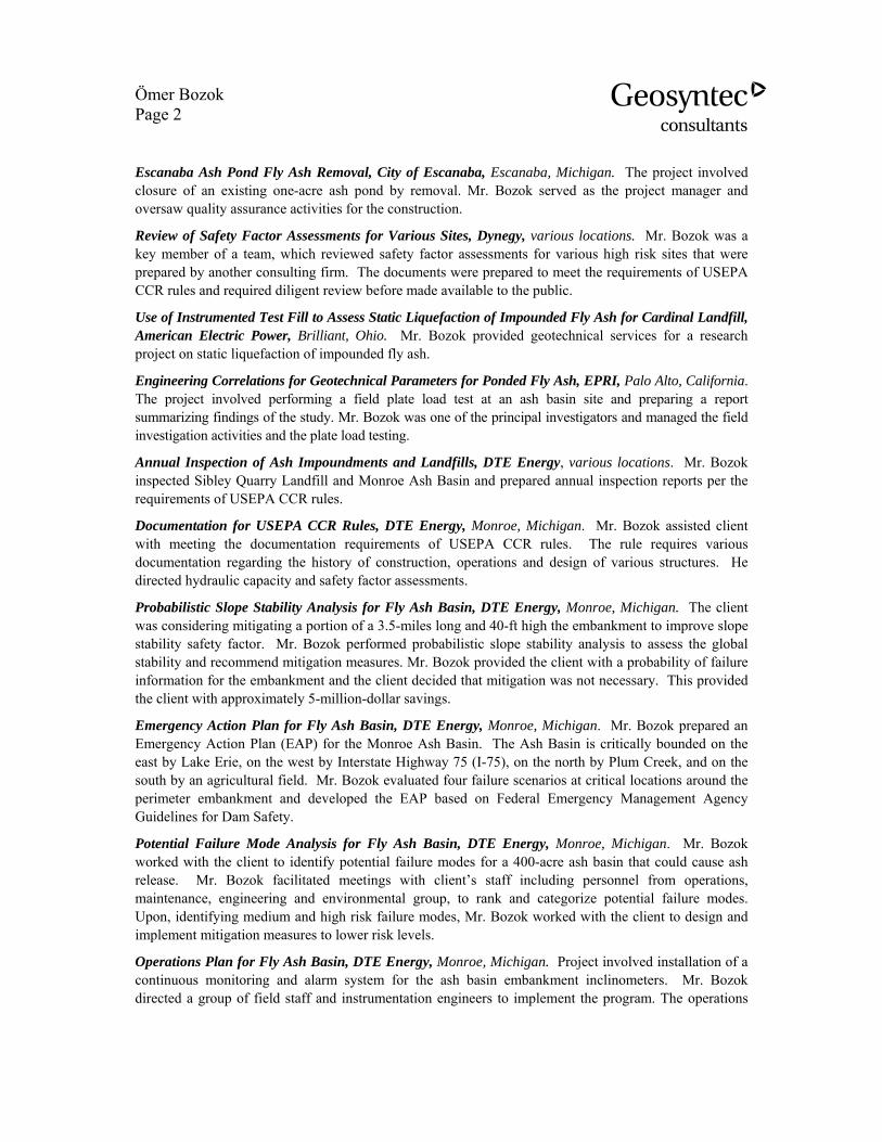
Ömer Bozok Page 2
Escanaba Ash Pond Fly Ash Removal, City of Escanaba, Escanaba, Michigan. The project involved closure of an existing one-acre ash pond by removal. Mr. Bozok served as the project manager and oversaw quality assurance activities for the construction.
Review of Safety Factor Assessments for Various Sites, Dynegy, various locations. Mr. Bozok was a key member of a team, which reviewed safety factor assessments for various high risk sites that were prepared by another consulting firm. The documents were prepared to meet the requirements of USEPA CCR rules and required diligent review before made available to the public.
Use of Instrumented Test Fill to Assess Static Liquefaction of Impounded Fly Ash for Cardinal Landfill, American Electric Power, Brilliant, Ohio. Mr. Bozok provided geotechnical services for a research project on static liquefaction of impounded fly ash.
Engineering Correlations for Geotechnical Parameters for Ponded Fly Ash, EPRI, Palo Alto, California. The project involved performing a field plate load test at an ash basin site and preparing a report summarizing findings of the study. Mr. Bozok was one of the principal investigators and managed the field investigation activities and the plate load testing.
Annual Inspection of Ash Impoundments and Landfills, DTE Energy, various locations. Mr. Bozok inspected Sibley Quarry Landfill and Monroe Ash Basin and prepared annual inspection reports per the requirements of USEPA CCR rules.
Documentation for USEPA CCR Rules, DTE Energy, Monroe, Michigan. Mr. Bozok assisted client with meeting the documentation requirements of USEPA CCR rules. The rule requires various documentation regarding the history of construction, operations and design of various structures. He directed hydraulic capacity and safety factor assessments.
Probabilistic Slope Stability Analysis for Fly Ash Basin, DTE Energy, Monroe, Michigan. The client was considering mitigating a portion of a 3.5-miles long and 40-ft high the embankment to improve slope stability safety factor. Mr. Bozok performed probabilistic slope stability analysis to assess the global stability and recommend mitigation measures. Mr. Bozok provided the client with a probability of failure information for the embankment and the client decided that mitigation was not necessary. This provided the client with approximately 5-million-dollar savings.
Emergency Action Plan for Fly Ash Basin, DTE Energy, Monroe, Michigan. Mr. Bozok prepared an Emergency Action Plan (EAP) for the Monroe Ash Basin. The Ash Basin is critically bounded on the east by Lake Erie, on the west by Interstate Highway 75 (I-75), on the north by Plum Creek, and on the south by an agricultural field. Mr. Bozok evaluated four failure scenarios at critical locations around the perimeter embankment and developed the EAP based on Federal Emergency Management Agency Guidelines for Dam Safety.
Potential Failure Mode Analysis for Fly Ash Basin, DTE Energy, Monroe, Michigan. Mr. Bozok worked with the client to identify potential failure modes for a 400-acre ash basin that could cause ash release. Mr. Bozok facilitated meetings with client’s staff including personnel from operations, maintenance, engineering and environmental group, to rank and categorize potential failure modes. Upon, identifying medium and high risk failure modes, Mr. Bozok worked with the client to design and implement mitigation measures to lower risk levels.
Operations Plan for Fly Ash Basin, DTE Energy, Monroe, Michigan. Project involved installation of a continuous monitoring and alarm system for the ash basin embankment inclinometers. Mr. Bozok directed a group of field staff and instrumentation engineers to implement the program. The operations

Ömer Bozok Page 3
plan provides guidelines on how to safely operate the fly ash basin, structures, provides communication procedures, and provides action criteria for surface and subsurface instrumentation.
PUBLICATIONS
Bozok, O., Sabatini, P.J., Amaya, P. (2013) “Use of Instrumented Test Fill to Assess Static Liquefaction of Impounded Fly Ash” World of Coal Ash Conference 2013, Lexington, KY
Bozok, O., Tanyu, B.F., Sabatini, P.J., Seymour, J.S. (2015) “Reliability Analysis of an Existing Ash Basin Embankment” World of Coal Ash Conference 2015, Nashville, TN
Seymour, J.S., Bozok, O., Hughes, A., Bodine, B. (2015) “Conditions of Coal Ash Embankments” World of Coal Ash Conference 2015, Nashville, TN
Sabatini, P.J., Bozok, O., Andonyadis, P., Yafrate, N. (2014) “Engineering Correlations for Geotechnical Parameters for Ponded Fly Ash”, EPRI Document #3002001151, July 2014
Tanyu, B.F., Neal, W., Seymour, J.P., Bodine, D., Bozok, O. (2011) “Case Study: Stability of Two Horizontal to One Vertical Embankment” ASCE, Geo-Frontiers Conference, March, Dallas, Texas.

APPENDIX B
2018 ANNUAL INSPECTION FORMS AND PHOTOS

MONROE VERTICAL EXTENSION LANDFILL 2018 ANNUAL INSPECTION FORM
Name of Landfill: Qualified Engineer: Omer BozokMDEQ Landfill ID Date:Owner: DTE Electric Company Weather: Raining, High 40sOperator: Headwaters Precipitation (since last inspection): 1 in.Site Conditions: Wet
I. Landfill Condition1. Describe operations in the landfill:
Other: Yes x No
If 'Yes', describe (type of debris, reason for obstruction, etc.)Ditches have minimal slope and standing water in some areas; Does not impede overall ability to drain the 24-hour, 25-year storm.
x Yes NoIf 'Yes', describe what type and its condition (rill, gully, dimensions, etc.)Numerous erosion rills and gullies were observed on the perimeter access berm and perimeter clay berm.
4. Is runoff from the landfill surface contained by the perimeter ditch or Ash Basin? x Yes No
x Yes NoIf 'No', describe where runoff flow is not contained.
6. Is the underdrain collection system draining? Yes NoMany of the underdrain collection system drains have sediment build up.
Only one of the pipes were draining at the time of inspection.
Yes x NoIf 'Yes', describe.
8. Other observations around the landfill (changes since last inspection): Yes x NoIf 'Yes', describe.
Monroe Vertical Extension LandfillTime:
Disposal of fly ash, bottom ash, economizer ash, FGD sludge
2. Are any stormwater ditches obstructed?
3. Are there indications of erosion on the landfill perimeter berm?
5. Is runon prevented from entering the landfill area?
Describe flow conditions.
7. Is there any unusual settlement causing "birdbaths"?
If 'No', describe where runoff flow is not contained.
4/24/2018 1:00:00 PM397800
Page 1 of 2

MONROE VERTICAL EXTENSION LANDFILL 2018 ANNUAL INSPECTION FORM
Name of Landfill: Qualified Engineer: Omer BozokMDEQ Landfill ID Date:
Monroe Vertical Extension LandfillTime:4/24/2018 1:00:00 PM397800
II. Repairs, Maintenance, Action Items1. Has any routine maintenance been conducted since the last inspection? Yes x No
If 'Yes', describe.
2. Have any repairs been made since the last inspection? Yes x NoIf 'Yes', describe.
3. Has this inspection identified any need for repair or maintenance? x Yes No
Numerous erosion rills and gullies were observed on the perimeter access berm and perimeter clay berm. Not urgent.
4. Are the instrumentation intact and functioning? Yes x NoIf 'No', describe conditions of instrumentation.
III. Photography
Location Direction of Photo Descriptioni. See attached photo logii.iii.iv.v.vi.vii.viii.ix.x.
PZ #9 was periodically recording inaccurate water level measurements (around El 900 ft). Instrumentation cables were reconnected to the data logger during inspection. Since then, water level measurements have been around El 610 ft, which is consistent with other piezometers.
Photographs can be taken of notable features. List of photographs:
If 'Yes', describe and state the urgency of maintenance. "Urgent" for maintenance that should be conducted as soon as possible, "Moderate" for maintenance that should be conducted within three months, and "Not Urgent" for maintenance that can be conducted within a year.
Page 2 of 2

/VERTICAL EXTENSION PHOTOLOG 1 18.06.27
GEOSYNTEC CONSULTANTS Photographic Record
Client: DTE Electric Company Project Number: CHE8242
Site Name: Monroe Power Plant Vertical Extension Landfill Site Location: Monroe, MI
Photograph ID: 1
Date: 4/24/2018
Direction: W
Comments: Photo taken at Station ~53+00. Minor erosion rills observed on perimeter access road embankment.
Photograph ID: 2
Date: 4/24/2018
Direction: S
Comments: Photo taken at Station ~53+00. erosion rills observed on perimeter access road embankment.

/VERTICAL EXTENSION PHOTOLOG 2 18.06.27
GEOSYNTEC CONSULTANTS Photographic Record
Client: DTE Electric Company Project Number: CHE8242
Site Name: Monroe Power Plant Vertical Extension Landfill Site Location: Monroe, MI
Photograph ID: 3
Date: 4/24/2018
Direction: W
Comments: Photo taken at Station ~55+00. Areas of sparse vegetation observed on perimeter clay embankment.
Photograph ID: 4
Date: 4/24/2018
Direction: E
Comments: Photo taken at Station ~60+00. Low spot observed between perimeter access road embankment and perimeter clay embankment.

/VERTICAL EXTENSION PHOTOLOG 3 18.06.27
GEOSYNTEC CONSULTANTS Photographic Record
Client: DTE Electric Company Project Number: CHE8242
Site Name: Monroe Power Plant Vertical Extension Landfill Site Location: Monroe, MI
Photograph ID: 5
Date: 4/24/2018
Direction: S
Comments: Photo taken at Station ~70+00. Low spot observed between perimeter access road embankment and perimeter clay embankment.
Photograph ID: 6
Date: 4/24/2018
Direction: -
Comments: Photo taken at Station ~72+00. Typical sediment buildup in a pore pressure relief drain.

/VERTICAL EXTENSION PHOTOLOG 4 18.06.27
GEOSYNTEC CONSULTANTS Photographic Record
Client: DTE Electric Company Project Number: CHE8242
Site Name: Monroe Power Plant Vertical Extension Landfill Site Location: Monroe, MI
Photograph ID: 7
Date: 4/24/2018
Direction: E
Comments: Photo taken at Station ~78+00. Erosion gully observed on perimeter clay embankment.
Photograph ID: 8
Date: 4/24/2018
Direction: SE
Comments: Photo taken at Station ~78+00. General condition of perimeter clay embankment.

/VERTICAL EXTENSION PHOTOLOG 5 18.06.27
GEOSYNTEC CONSULTANTS Photographic Record
Client: DTE Electric Company Project Number: CHE8242
Site Name: Monroe Power Plant Vertical Extension Landfill Site Location: Monroe, MI
Photograph ID: 9
Date: 4/24/2018
Direction: NW
Comments: General condition of Phase 2 area.