2001 sterling acterra maintenance manual - … · foreword when performed on a regular basis,...
TRANSCRIPT

ACTERRA MAINTENANCE MANUAL
Models: MX
STI-403 (8/05P) Published byFreightliner LLC
4747 N. Channel Ave.Portland, OR 97217
Printed in U.S.A.

ForewordWhen performed on a regular basis, lubricating the parts of your vehicle is the least costly wayof obtaining safe and reliable vehicle operation. Added benefits and savings occur when youcheck that the engine, undercarriage, and noise emission control parts are in good working orderduring lubrication.
This maintenance manual explains when you should lubricate parts and what to look for whenchecking for wear or damage. For daily and weekly checks, refer to the vehicle driver’s manual.
IMPORTANT: Descriptions and specifications in this manual were in effect at the time ofprinting. Sterling Truck Corporation reserves the right to discontinue models and tochange specifications or design at any time without notice and without incurringobligation. Descriptions and specifications contained in this publication provide nowarranty, expressed or implied, and are subject to revision and editions without notice.
For additional information, please contact Freightliner LLC, Service Systems and Documenta-tion, P.O. Box 3849, Portland, OR 97208-3849, U.S.A. or refer to http://www.Freightliner.com andhttp://www.SterlingTrucks.com.
Environmental Concerns and RecommendationsWhenever you see instructions in this manual to discard materials, you should attempt to reclaimand recycle them. To preserve our environment, follow appropriate environmental rules andregulations when disposing of materials.
NOTICE: Parts Replacement ConsiderationsDo not replace suspension, axle, or steering parts (such as springs, wheels, hubs, and steeringgears) with used parts. Used parts may have been subjected to collisions or improper use andhave undetected structural damage.
© 2000-2005 Freightliner LLC
All rights reserved. No part of this publication, in whole or in part, may be translated, reproduced,stored in a retrieval system, or transmitted in any form by any means, electronic, mechanical,photocopying, recording, or otherwise, without the prior written permission of Freightliner LLC.
Freightliner LLCService Systems and Documentation (POC-SSD)
P.O. Box 3849Portland, OR 97208–3849

Freightliner LLC distributes the following major service publications.
Workshop Manual Workshop manuals contain service and repair information for all vehicle sys-tems and components, except for major components such as engines, transmis-sions, and rear axles. Each workshop manual section is divided into subjectsthat can include general information, principles of operation, removal, disassem-bly, assembly, installation, specifications, and troubleshooting.
Maintenance Manual Maintenance manuals contain routine maintenance procedures and intervals forvehicle components and systems. They have information such as lubricationprocedures and tables, fluid replacement procedures, fluid capacities, specifica-tions, procedures for adjustments and for checking the tightness of fasteners.Maintenance manuals do not contain detailed repair or service information.
Driver’s Manual Driver’s manuals contain information needed to enhance the driver’s under-standing of how to operate and care for the vehicle and its components. Eachmanual contains a chapter that covers pretrip inspection and daily maintenanceof vehicle components. Driver’s manuals do not contain detailed repair or ser-vice information.
Parts Technical Manual Freightliner LLC publishes this manual to aid in the identification of serviceablereplacement vehicle parts. This manual is used in conjunction with the partsbook and the service parts catalog microfiche.
Service Bulletins Service bulletins provide the latest service tips, field repairs, product improve-ments, and related information. Some service bulletins are updates to informa-tion in the workshop manual. These bulletins take precedence over workshopmanual information, until the latter is updated; at that time, the bulletin is usuallycanceled. The service bulletins manual is available only to dealers. When doingservice work on a vehicle system or part, check for a valid service bulletin forthe latest information on the subject.
IMPORTANT: Before using a particular service bulletin, check the currentservice bulletin validity list to be sure the bulletin is valid.
Recall Bulletins These bulletins pertain to special situations that involve service work or replace-ment of parts in connection with a recall notice. Recall bulletins pertain to mat-ters of vehicle safety. All bulletins are distributed to dealers; customers receivenotices that apply to their vehicles.
Field ServiceModifications
This publication is concerned with non-safety-related service work or replace-ment of parts. All field service modifications are distributed to dealers; custom-ers receive notices that apply to their vehicles.
IntroductionDescriptions of Service Publications
Acterra Maintenance Manual, January 2003 I–1

For a page example of the printed manual, see Fig. 1 .
02/11/2002 f020103
A B C
D E
Frame and Fifth Wheel 31
31−01 Frame Fastener TorqueChecking
31−02 Fifth Wheel Inspecting andLubricating
Acterra Trucks Maintenance Manual, April 2000 31/1
FONTANE
HOLLAND
CAUTION:
A. Maintenance Operation Number consists of the Group Number followed by the Sequence NumberB. Group TitleC. Group NumberD. Release DateE. Group Number/Page Number
Fig. 1, Page Example of the Printed Manual
IntroductionPage Description
I–2 Acterra Maintenance Manual, January 2003

Group No. Group Title
00 . . . . . . . . . . . . . . . . . . . . . . General Information01 . . . . . . . . . . . . . . . . . . . . . . . . . . . . . . . . Engine09 . . . . . . . . . . . . . . . . . . . . . . . . . . . . . . Air Intake13 . . . . . . . . . . . . . . . . . . . . . . . . . Air Compressor15 . . . . . . . . . . . . . . . . . . . Alternators and Starters20 . . . . . . . . . . . . . . . . . . . Engine Cooling/Radiator25 . . . . . . . . . . . . . . . . . . . . . . . . . . . . . . . . Clutch26 . . . . . . . . . . . . . . . . . . . . . . . . . . . Transmission31 . . . . . . . . . . . . . Frame and Frame Components32 . . . . . . . . . . . . . . . . . . . . . . . . . . . . Suspension33 . . . . . . . . . . . . . . . . . . . . . . . . . . . . . Front Axle35 . . . . . . . . . . . . . . . . . . . . . . . . . . . . . Rear Axle40 . . . . . . . . . . . . . . . . . . . . . . . . Wheels and Tires41 . . . . . . . . . . . . . . . . . . . . . . . . . . . . . . Driveline42 . . . . . . . . . . . . . . . . . . . . . . . . . . . . . . . . Brakes46 . . . . . . . . . . . . . . . . . . . . . . . . . . . . . . . Steering47 . . . . . . . . . . . . . . . . . . . . . . . . . . . . . . . . . Fuel49 . . . . . . . . . . . . . . . . . . . . . . . . . . . . . . . Exhaust54 . . . . . . . . . . Electrical, Instruments, and Controls72 . . . . . . . . . . . . . . . . . . . . . . . . . . . . . . . . Doors83 . . . . . . . . . . . . . . . . . Heater and Air Conditioner
IntroductionActerra Maintenance Manual Contents
Acterra Maintenance Manual, January 2003 I–3

Title of Maintenance Operation (MOP) MOP Number
Initial Maintenance (IM) Operations Table . . . . . . . . . . . . . . . . . . . . . . . . . . . . . . . . . . . . . . . . . . . . . . . . 00–09
Lubrication and Fluid Level Check (M1). . . . . . . . . . . . . . . . . . . . . . . . . . . . . . . . . . . . . . . . . . . . . . . . . . 00–15
Lubrication and Fluid Level Check (M2). . . . . . . . . . . . . . . . . . . . . . . . . . . . . . . . . . . . . . . . . . . . . . . . . . 00–16
M1 Maintenance Interval Operations Table . . . . . . . . . . . . . . . . . . . . . . . . . . . . . . . . . . . . . . . . . . . . . . . 00–10
M2 Maintenance Interval Operations Table . . . . . . . . . . . . . . . . . . . . . . . . . . . . . . . . . . . . . . . . . . . . . . . 00–11
M3 Maintenance Interval Operations Table . . . . . . . . . . . . . . . . . . . . . . . . . . . . . . . . . . . . . . . . . . . . . . . 00–12
M4 Maintenance Interval Operations Table . . . . . . . . . . . . . . . . . . . . . . . . . . . . . . . . . . . . . . . . . . . . . . . 00–13
M5 Maintenance Interval Operations Table . . . . . . . . . . . . . . . . . . . . . . . . . . . . . . . . . . . . . . . . . . . . . . . 00–14
Maintenance Interval Tables . . . . . . . . . . . . . . . . . . . . . . . . . . . . . . . . . . . . . . . . . . . . . . . . . . . . . . . . . . 00–07
Maintenance Operation Sets Tables . . . . . . . . . . . . . . . . . . . . . . . . . . . . . . . . . . . . . . . . . . . . . . . . . . . . 00–08
Maintenance Schedule Table . . . . . . . . . . . . . . . . . . . . . . . . . . . . . . . . . . . . . . . . . . . . . . . . . . . . . . . . . 00–06
Metric/U.S. Customary Conversion Tables. . . . . . . . . . . . . . . . . . . . . . . . . . . . . . . . . . . . . . . . . . . . . . . . 00–04
Noise Emission Control Systems Maintenance . . . . . . . . . . . . . . . . . . . . . . . . . . . . . . . . . . . . . . . . . . . . 00–01
Scheduled Maintenance Intervals, Description and Use. . . . . . . . . . . . . . . . . . . . . . . . . . . . . . . . . . . . . . 00–05
Torque Specifications Tables. . . . . . . . . . . . . . . . . . . . . . . . . . . . . . . . . . . . . . . . . . . . . . . . . . . . . . . . . . 00–03
Verification of Inspections Log. . . . . . . . . . . . . . . . . . . . . . . . . . . . . . . . . . . . . . . . . . . . . . . . . . . . . . . . . 00–02
General Information 00Index, Alphabetical
Acterra Maintenance Manual, June 2005

General Information
Federal Law, Part 205: TransportationEquipment Noise Emission ControlsPart 205, Transportation Equipment Noise EmissionControls, requires the vehicle manufacturer to fur-nish, with each new vehicle, such written instructionsfor the proper maintenance, use, and repair of thevehicle by the ultimate purchaser to provide reason-able assurance of the elimination or minimization ofnoise emission degradation throughout the life of thevehicle. In compliance with the law, the Noise Emis-sion Control Systems maintenance located in eachapplicable group within this manual, in conjunctionwith the vehicle workshop manual, provides theseinstructions to owners.
Normal Vehicle UseThe maintenance instructions contained in thismanual are based on average vehicle use and nor-mal operating conditions. Unusual vehicle operatingconditions may require service at more frequent in-tervals.
Recommendations for ReplacementPartsReplacement parts used for maintenance or for therepair of noise emission control systems should begenuine Sterling parts. If other than genuine Sterlingparts are used for replacements or for the repair ofcomponents affecting noise emission control, theowner should be sure that such parts are warrantedby their manufacturer to be equivalent to genuineSterling parts in performance and durability.
Sterling Noise Emissions WarrantySee the vehicle owner’s warranty information bookfor warranty information concerning noise emissioncontrol systems.
Tampering With the Noise ControlSystem Is ProhibitedFederal law prohibits the following acts or the caus-ing thereof: (1) the removal or rendering inoperativeby any person other than for purposes of mainte-nance, repair, or replacement, of any device or ele-ment of design incorporated into any new vehicle for
the purpose of noise control prior to its sale or deliv-ery to the ultimate purchaser or while it is in use, or(2) the use of the vehicle after such device or ele-ment of design has been removed or rendered inop-erative by any person. Among those acts presumedto constitute tampering are the acts listed below:
A. Removal of engine noise-deadening panels.
B. Removal of or rendering the engine speed gover-nor inoperative so as to allow engine speed toexceed manufacturer’s specifications.
C. Removal of or rendering inoperative the fanclutch, including by-passing the control on anythermostatic fan drive to cause it to operate con-tinuously.
D. Removal of the fan shroud.
E. Removal of or rendering inoperative exhaust sys-tem components, including exhaust pipe clamp-ing.
F. Removal of air intake system components.
G. Removal of hood liners (noise-deadening pan-els).
Maintenance InstructionsScheduled intervals are in the maintenance tables inGroup 00 of this manual. A "Verification of Inspec-tions Log" is contained in the following table, andshould be filled in each time the noise emission con-trols on the vehicle are maintained or repaired.
General Information 00Noise Emission Control Systems Maintenance: 00–01
Acterra Maintenance Manual, June 2005 00/1

Verification of Inspections LogVerification of Inspections Log — Group 20
Verification of Inspections Log — Group 20 — Engine Cooling/Radiator
Date Mileage Repair Description Cost Repair Facility
Verification of Inspections Log — Group 49
Verification of Inspections Log — Group 49 — Exhaust
Date Mileage Repair Description Cost Repair Facility
General Information00Verification of Inspections Log: 00–02
Acterra Maintenance Manual, June 200500/2

Torque Values for U.S. Customary Thread Fasteners With Lubricated * or Plated Threads †
ThreadDiameter–
Pitch
Regular Hex Flanged
Grade 5Bolt
Grade 5 orB Nut
Grade 8 or8.2 Bolt
Grade 8 orC Nut
Grade 5Bolt
Grade BNut
Grade 8 or8.2 Bolt
Grade GNut
Torque: lbf·ft (N·m) Torque: lbf·ft (N·m) Torque: lbf·ft (N·m) Torque: lbf·ft (N·m)
f230002 f230003 f230004 f230005 f230006 f230007 f230008 f230009
1/4–20 7 (9) 8 (11) 6 (8) 10 (14)
1/4–28 8 (11) 9 (12) 7 (9) 12 (16)
5/16–18 15 (20) 16 (22) 13 (18) 21 (28)
5/16–24 16 (22) 17 (23) 14 (19) 23 (31)
3/8–16 26 (35) 28 (38) 23 (31) 37 (50)
3/8–24 30 (41) 32 (43) 25 (34) 42 (57)
7/16–14 42 (57) 45 (61) 35 (47) 60 (81)
7/16–20 47 (64) 50 (68) 40 (54) 66 (89)
1/2–13 64 (87) 68 (92) 55 (75) 91 (123)
1/2–20 72 (98) 77 (104) 65 (88) 102 (138)
9/16–12 92 (125) 98 (133) 80 (108) 130 (176)
9/16–18 103 (140) 110 (149) 90 (122) 146 (198)
5/8–11 128 (173) 136 (184) 110 (149) 180 (244)
5/8–18 145 (197) 154 (209) 130 (176) 204 (277)
3/4–10 226 (306) 241 (327) 200 (271) 320 (434)
3/4–16 253 (343) 269 (365) 220 (298) 357 (484)
7/8–9 365 (495) 388 (526) 320 (434) 515 (698)
7/8–14 402 (545) 427 (579) 350 (475) 568 (770)
1–8 — 582 (789) — —
1–12 — 637 (863) — —
1–14 — 652 (884) — —* Sterling recommends that all plated and unplated fasteners be coated with oil before installation.† Use these torque values if either the bolt or nut is lubricated or plated (zinc-phosphate conversion-coated, cadmium-plated, or waxed).
Table 1, Torque Values for U.S. Customary Thread Fasteners With Lubricated or Plated Threads
General Information 00Torque Specifications Tables: 00–03
Acterra Maintenance Manual, June 2005 00/3

Torque Values for U.S. Customary Thread Fasteners With Dry (Unlubricated) * Plain (Unplated) Threads †
ThreadDiameter–Pitch
Regular Hex Flanged
Grade 5 Bolt Grade 5 or BNut
Grade 8 or 8.2Bolt
Grade 8 or CNut
Grade 8 or 8.2Bolt Grade G Nut
Torque: lbf·ft (N·m) Torque: lbf·ft (N·m) Torque: lbf·ft (N·m)
f230002 f230003 f230004 f230005 f230008 f230009
1/4–20 8 (11) 10 (14) —
1/4–28 9 (12) 12 (16) —
5/16–18 15 (20) 22 (30) 22 (30)
5/16–24 17 (23) 25 (34) —
3/8–16 28 (38) 40 (54) 40 (54)
3/8–24 31 (42) 45 (61) —
7/16–14 45 (61) 65 (88) 65 (88)
7/16–20 50 (68) 70 (95) —
1/2–13 70 (95) 95 (129) 95 (129)
1/2–20 75 (102) 110 (149) —
9/16–12 100 (136) 140 (190) 140 (190)
9/16–18 110 (149) 155 (210) —
5/8–11 135 (183) 190 (258) 190 (258)
5/8–18 155 (210) 215 (292) —
3/4–10 240 (325) 340 (461) 340 (461)
3/4–16 270 (366) 380 (515) —
7/8–9 385 (522) 540 (732) —
7/8–14 425 (576) 600 (813) —
1–8 580 (786) 820 (1112) —
1–12 635 (861) 900 (1220) —
1–14 650 (881) 915 (1241) —* Threads may have residual oil, but will be dry to the touch.† Male and female threads (bolt and nut) must both be unlubricated and unplated; if either is plated or lubricated, use Table 1 . Sterling recommends that all
plated and unplated fasteners be coated with oil before installation.
Table 2, Torque Values for U.S. Customary Thread Fasteners With Dry (Unlubricated) Plain (Unplated) Threads
General Information00Torque Specifications Tables: 00–03
Acterra Maintenance Manual, June 200500/4

Torque Values for Metric Thread Fasteners With Lubricated * or Plated Threads †
ThreadDiameter–Pitch
Class 8.8 Bolt Class 8 Nut Class 10.9 Bolt Class 10 Nut
Torque: lbf·ft (N·m) Torque: lbf·ft (N·m)
f230010
8.8
f230011
8
f230012
10.9
f230013
10
M6 5 (7) 7 (9)
M8 12 (16) 17 (23)
M8 x 1 13 (18) 18 (24)
M10 24 (33) 34 (46)
M10 x 1.25 27 (37) 38 (52)
M12 42 (57) 60 (81)
M12 x 1.5 43 (58) 62 (84)
M14 66 (89) 95 (129)
M14 x 1.5 72 (98) 103 (140)
M16 103 (140) 148 (201)
M16 x 1.5 110 (149) 157 (213)
M18 147 (199) 203 (275)
M18 x 1.5 165 (224) 229 (310)
M20 208 (282) 288 (390)
M20 x 1.5 213 (313) 320 (434)
M22 283 (384) 392 (531)
M22 x 1.5 315 (427) 431 (584)
M24 360 (488) 498 (675)
M24 x 2 392 (531) 542 (735)
M27 527 (715) 729 (988)
M27 x 2 569 (771) 788 (1068)
M30 715 (969) 990 (1342)
M30 x 2 792 (1074) 1096 (1486)* Sterling recommends that all plated and unplated fasteners be coated with oil before installation.† Use these torque values if either the bolt or nut is lubricated or plated (zinc-phosphate conversion-coated,
cadmium-plated, or waxed).
Table 3, Torque Values for Metric Thread Fasteners With Lubricated or PlatedThreads
General Information 00Torque Specifications Tables: 00–03
Acterra Maintenance Manual, June 2005 00/5

When You Know U.S.Customary
MultiplyBy To Get Metric When You
Know MetricMultiply
By To Get U.S. Customary
Length
inches (in) 25.4 millimeters (mm) 0.03937 inches (in)
inches (in) 2.54 centimeters (cm) 0.3937 inches (in)
feet (ft) 0.3048 meters (m) 3.281 feet (ft)
yards (yd) 0.9144 meters (m) 1.094 yards (yd)
miles (mi) 1.609 kilometers (km) 0.6215 miles (mi)
Area
square inches (in2) 645.16 square millimeters (mm2) 0.00155 square inches (in2)
square inches (in2) 6.452 square centimeters (cm2) 0.155 square inches (in2)
square feet (ft2) 0.0929 square meters (m2) 10.764 square feet (ft2)
Volume
cubic inches (in3) 16387.0 cubic millimeter (mm3) 0.000061 cubic inches (in3)
cubic inches (in3) 16.387 cubic centimeters (cm3) 0.06102 cubic inches (in3)
cubic inches (in3) 0.01639 liters (L) 61.024 cubic inches (in3)
fluid ounces (fl oz) 29.54 milliliters (mL) 0.03381 fluid ounces (fl oz)
pints (pt) 0.47318 liters (L) 2.1134 pints (pt)
quarts (qt) 0.94635 liters (L) 1.0567 quarts (qt)
gallons (gal) 3.7854 liters (L) 0.2642 gallons (gal)
cubic feet (ft3) 28.317 liters (L) 0.03531 cubic feet (ft3)
cubic feet (ft3) 0.02832 cubic meters (m3) 35.315 cubic feet (ft3)
Weight/Force
ounces (av) (oz) 28.35 grams (g) 0.03527 ounces (av) (oz)
pounds (av) (lb) 0.454 kilograms (kg) 2.205 pounds (av) (lb)
U.S. tons (t) 907.18 kilograms (kg) 0.001102 U.S. tons (t)
U.S. tons (t) 0.90718 metric tons (t) 1.1023 U.S. tons (t)
Torque/Work Force
inch–pounds (lbf·in) 11.298 Newton–centimeters (N·cm) 0.08851 inch–pounds (lbf·in)
foot–pounds (lbf·ft) 1.3558 Newton–meters (N·m) 0.7376 foot–pounds (lbf·ft)
Pressure/Vacuum
inches of mercury (inHg) 3.37685 kilo Pascals (kPa) 0.29613 inches of mercury (inHg)
pounds per square inch (psi) 6.895 kilo Pascals (kPa) 0.14503 pounds per square inch (psi)
Table 4, Metric/U.S. Customary Conversion
When You Know Subtract ThenDivide By To Get When You
KnowMultiply
ByThenAdd To Get
degrees Fahrenheit (°F) 32 1.8 degrees Celsius (°C) 1.8 32 degrees Fahrenheit (°F)
Table 5, Temperature Conversion
General Information00Metric/U.S. Customary Conversion Tables: 00–04
Acterra Maintenance Manual, June 200500/6
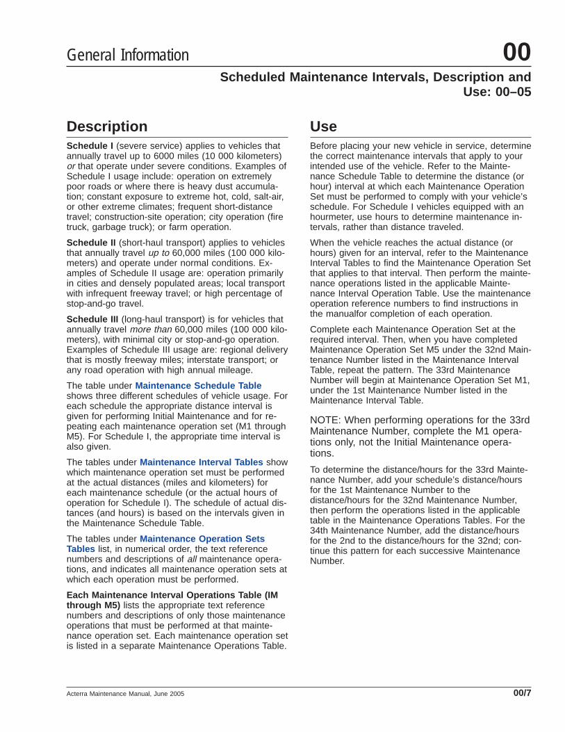
DescriptionSchedule I (severe service) applies to vehicles thatannually travel up to 6000 miles (10 000 kilometers)or that operate under severe conditions. Examples ofSchedule I usage include: operation on extremelypoor roads or where there is heavy dust accumula-tion; constant exposure to extreme hot, cold, salt-air,or other extreme climates; frequent short-distancetravel; construction-site operation; city operation (firetruck, garbage truck); or farm operation.
Schedule II (short-haul transport) applies to vehiclesthat annually travel up to 60,000 miles (100 000 kilo-meters) and operate under normal conditions. Ex-amples of Schedule II usage are: operation primarilyin cities and densely populated areas; local transportwith infrequent freeway travel; or high percentage ofstop-and-go travel.
Schedule III (long-haul transport) is for vehicles thatannually travel more than 60,000 miles (100 000 kilo-meters), with minimal city or stop-and-go operation.Examples of Schedule III usage are: regional deliverythat is mostly freeway miles; interstate transport; orany road operation with high annual mileage.
The table under Maintenance Schedule Tableshows three different schedules of vehicle usage. Foreach schedule the appropriate distance interval isgiven for performing Initial Maintenance and for re-peating each maintenance operation set (M1 throughM5). For Schedule I, the appropriate time interval isalso given.
The tables under Maintenance Interval Tables showwhich maintenance operation set must be performedat the actual distances (miles and kilometers) foreach maintenance schedule (or the actual hours ofoperation for Schedule I). The schedule of actual dis-tances (and hours) is based on the intervals given inthe Maintenance Schedule Table.
The tables under Maintenance Operation SetsTables list, in numerical order, the text referencenumbers and descriptions of all maintenance opera-tions, and indicates all maintenance operation sets atwhich each operation must be performed.
Each Maintenance Interval Operations Table (IMthrough M5) lists the appropriate text referencenumbers and descriptions of only those maintenanceoperations that must be performed at that mainte-nance operation set. Each maintenance operation setis listed in a separate Maintenance Operations Table.
UseBefore placing your new vehicle in service, determinethe correct maintenance intervals that apply to yourintended use of the vehicle. Refer to the Mainte-nance Schedule Table to determine the distance (orhour) interval at which each Maintenance OperationSet must be performed to comply with your vehicle’sschedule. For Schedule I vehicles equipped with anhourmeter, use hours to determine maintenance in-tervals, rather than distance traveled.
When the vehicle reaches the actual distance (orhours) given for an interval, refer to the MaintenanceInterval Tables to find the Maintenance Operation Setthat applies to that interval. Then perform the mainte-nance operations listed in the applicable Mainte-nance Interval Operation Table. Use the maintenanceoperation reference numbers to find instructions inthe manualfor completion of each operation.
Complete each Maintenance Operation Set at therequired interval. Then, when you have completedMaintenance Operation Set M5 under the 32nd Main-tenance Number listed in the Maintenance IntervalTable, repeat the pattern. The 33rd MaintenanceNumber will begin at Maintenance Operation Set M1,under the 1st Maintenance Number listed in theMaintenance Interval Table.
NOTE: When performing operations for the 33rdMaintenance Number, complete the M1 opera-tions only, not the Initial Maintenance opera-tions.
To determine the distance/hours for the 33rd Mainte-nance Number, add your schedule’s distance/hoursfor the 1st Maintenance Number to thedistance/hours for the 32nd Maintenance Number,then perform the operations listed in the applicabletable in the Maintenance Operations Tables. For the34th Maintenance Number, add the distance/hoursfor the 2nd to the distance/hours for the 32nd; con-tinue this pattern for each successive MaintenanceNumber.
General Information 00Scheduled Maintenance Intervals, Description and
Use: 00–05
Acterra Maintenance Manual, June 2005 00/7

Maintenance Schedule Models Maintenance IntervalOperation
Maintenance Intervals
Frequency Miles Km Hours
Schedule I(Severe Service)
vehicles that annually travel upto 6000 miles (10 000 km)
All Initial Maintenance (IM) first 1000 1600 100
Maintenance 1 (M1) every 1000 1600 100
Maintenance 2 (M2) every 4000 6400 400
Maintenance 3 (M3) every 8000 12 800 800
Maintenance 4 (M4) every 16,000 25 600 1600
Maintenance 5 (M5) every 32,000 51 200 3200
Schedule II(Short-Haul Transport)
vehicles that annually travel upto 60,000 miles (100 000 km)
All Initial Maintenance (IM) first 8000 12 000
—
Maintenance 1 (M1) every 8000 12 000
Maintenance 2 (M2) every 16,000 24 000
Maintenance 3 (M3) every 32,000 48 000
Maintenance 4 (M4) every 64,000 96 000
Maintenance 5 (M5) every 128,000 192 000
Schedule III(Long-Haul Transport)
vehicles that annually travelover 60,000 miles (100 000
km)
All Initial Maintenance (IM) first 10,000 16 000
—
Maintenance 1 (M1) every 10,000 16 000
Maintenance 2 (M2) every 20,000 32 000
Maintenance 3 (M3) every 40,000 64 000
Maintenance 4 (M4) every 80,000 128 000
Maintenance 5 (M5) every 160,000 256 000
Table 6, Maintenance Schedule Table
General Information00Maintenance Schedule Table: 00–06
Acterra Maintenance Manual, June 200500/8

Maintenance Intervals for Schedule I
Maint. No. Maintenance Interval Miles km Hours
1 IM and M1 1000 1600 100
2 M1 2000 3200 200
3 M1 3000 4800 300
4 M1and M2 4000 6400 400
5 M1 5000 8000 500
6 M1 6000 9600 600
7 M1 7000 11 200 700
8 M1, M2, and M3 8000 12 800 800
9 M1 9000 14 400 900
10 M1 10,000 16 000 1000
11 M1 11,000 17 600 1100
12 M1 and M2 12,000 19 200 1200
13 M1 13,000 20 800 1300
14 M1 14,000 22 400 1400
15 M1 15,000 24 000 1500
16 M1, M2, M3, and M4 16,000 25 600 1600
17 M1 17,000 27 200 1700
18 M1 18,000 28 800 1800
19 M1 19,000 30 400 1900
20 M1 and M2 20,000 32 000 2000
21 M1 21,000 33 600 2100
22 M1 22,000 35 200 2200
23 M1 23,000 36 800 2300
24 M1, M2, and M3 24,000 38 400 2400
25 M1 25,000 40 000 2500
26 M1 26,000 41 600 2600
27 M1 27,000 43 200 2700
28 M1 and M2 28,000 44 800 2800
29 M1 29,000 46 400 2900
30 M1 30,000 48 000 3000
31 M1 31,000 49 600 3100
32 M1, M2, M3, M4, and M5 32,000 51 200 3200
Table 7, Maintenance Intervals for Schedule I
General Information 00Maintenance Interval Tables: 00–07
Acterra Maintenance Manual, June 2005 00/9

Maintenance Intervals for Schedules II and III (all models)
Maint.No. Maintenance Interval
Schedule II Schedule III
Miles km Miles km
1 IM and M1 8000 12 000 10,000 16 000
2 M1 and M2 16,000 24 000 20,000 32 000
3 M1 24,000 36 000 30,000 48 000
4 M1, M2, and M3 32,000 48 000 40,000 64 000
5 M1 40,000 60 000 50,000 80 000
6 M1 and M2 48,000 72 000 60,000 96 000
7 M1 56,000 84 000 70,000 112 000
8 M1, M2, M3, and M4 64,000 96 000 80,000 128 000
9 M1 72,000 108 000 90,000 144 000
10 M1 and M2 80,000 120 000 100,000 160 000
11 M1 88,000 132 000 110,000 176 000
12 M1, M2, and M3 96,000 144 000 120,000 192 000
13 M1 104,000 156 000 130,000 208 000
14 M1, and M2 112,000 168 000 140,000 224 000
15 M1 120,000 180 000 150,000 240 000
16 M1, M2, M3, M4, and M5 128,000 192 000 160,000 256 000
17 M1 136,000 204 000 170,000 272 000
18 M1 and M2 144,000 216 000 180,000 288 000
19 M1 152,000 228 000 190,000 304 000
20 M1, M2, and M3 160,000 240 000 200,000 320 000
21 M1 168,000 252 000 210,000 336 000
22 M1 and M2 176,000 264 000 220,000 352 000
23 M1 184,000 276 000 230,000 368 000
24 M1, M2, M3, and M4 192,000 288 000 240,000 384 000
25 M1 200,000 300 000 250,000 400 000
26 M1 and M2 208,000 312 000 260,000 416 000
27 M1 216,000 324 000 270,000 432 000
28 M1, M2, and M3 224,000 336,000 280,000 448 000
29 M1 232,000 348 000 290,000 464 000
30 M1 and M2 240,000 360 000 300,000 480 000
31 M1 248,000 372 000 310,000 496 000
32 M1, M2, M3, M4, and M5 256,000 384 000 320,000 512 000
Table 8, Maintenance Intervals for Schedules II and III (all models)
General Information00Maintenance Interval Tables: 00–07
Acterra Maintenance Manual, June 200500/10

IMPORTANT: At each Maintenance Operation Set, inaddition to the maintenance operations listed in thistable, perform all daily and weekly maintenance op-erations listed in the "Pretrip Inspection and DailyMaintenance" chapter of the vehicle driver’s manual.
NOTE: Maintenance operations appearing in italics inthis table are for noise emission control components.Numbers in this table are maintenance operation ref-erence numbers matching those in the text of thismanual.
Maintenance Operation Sets for Groups 00 through 32
REQUIRED MAINTENANCE OPERATION SET IM M1 M2 M3 M4 M5
Maintenance Operation Number and Operation Description
00–15 Lubrication and Fluid Level Check • • • • • •
00–16 Lubrication and Fluid Level Check • • • •
01–01 Engine-Support Fasteners Checking • •
01–02 Engine Drive Belt Inspecting • • •
01–03 Pacbrake Inspecting and Maintenance* • • •
09–01 Air Cleaner Element Inspecting and Replacing • • •
13–01 Air Compressor Inspecting, Bendix • • •
13–02 Air Compressor Rebuilding/Replacing, Bendix •
15–01 Alternator, Battery, and Starter Checking • •
20–01 Radiator Cap Checking • • • •
20–02 Radiator Pressure Flushing and Coolant Changing • •
20–03 Fan Clutch Checking • • • •
25–01 Clutch Release Bearing and Release Cross-Shaft Lubricating • • • • • •
25–02 Clutch (Pull-Type) Inspecting and Adjusting • • • •
25–03 Hydraulic Fluid Level Checking • • • • •
25–04 Hydraulic Fluid Replacing •
26–01 Manual Transmission Fluid Level Checking • • •
26–02 Eaton Fuller and TTC Transmission Fluid Changing and Magnetic Plug Cleaning •† • •
26–03 Allison, Eaton Fuller, and Meritor Transmission Breather Checking • • • •
26–04 Allison Transmission Fluid and Filter Changing • • •
26–05 Mercedes-Benz Transmission Fluid Changing and Magnetic Plug Cleaning •
26–06 Mercedes-Benz Transmission Leak Checking •
31–01 Frame Fastener Torque Checking • • •
31–02 Fifth Wheel Inspecting • • • • • •
31–03 Fifth Wheel Lubricating • • • • • •
32–01 Suspension Inspecting • • • • • •
32–02 Suspension Lubricating • • • • • •
32–03 U-Bolt Torque Checking • • • •* With frequent use, the Pacbrake Exhaust Brake will operate free of maintenance. However, if the vehicle is used inconsistently, sseasonally, or is exposed to
excess moisture, it will be necessary to perform preventative maintenance as instructed in Maintenance Operation 01–03.† IM interval does not apply to vehicles with a factory fill of Eaton approved synthetic lubricant.
Table 9, Maintenance Operation Sets for Groups 00 through 32
General Information 00Maintenance Operation Sets Tables: 00–08
Acterra Maintenance Manual, June 2005 00/11

Maintenance Operation Sets for Groups 33 through 42
REQUIRED MAINTENANCE OPERATION SET IM M1 M2 M3 M4 M5
Maintenance Operation Number and Operation Description
33–01 Knuckle Pin Lubricating • • • • • •
33–02 Tie-Rod End Inspecting • • • • • •
33–03 Tie-Rod End Lubricating • • • • • •
33–04 All-Axle Alignment Checking • • •
33–05 All-Wheel-Drive Front Axle Oil Level Checking • • •
33–06 All-Wheel-Drive Front Axle Oil Changing • • •
33–07 Draw Key Nut Inspecting • • • •
35–01 Axle Lubricant Level Checking • • •
35–02 Axle Breather Checking • • • • • •
35–03 Axle Lubricant Changing and Magnetic Plug Cleaning • • •
35–04 Two-Speed-Axle Shift Unit Oil Level Checking • •
35–05 Two-Speed-Axle Shift Unit Oil Changing • • •
40–01 Wheel Nut Checking • • •
41–01 Driveline Inspecting • • • • • •
41–02 Driveline Lubricating • • • • • •
42–01 Air Dryer Inspecting, Bendix AD–9 • • • • • •
42–02 Air Brake Valve Inspecting and Leak Checking, Bendix BP–R1 • • • • • •
42–03 Foot Brake Valve Actuator Lubricating, Bendix E–8P • • • • • •
42–04 Air Brake Valve Operation Checking • • • • • •
42–05 Relay Valve Checking, Midland • • • • • •
42–06 Quick Release and Flipper Valves Checking, Midland • • • • • •
42–07 Brake Chamber Inspecting (All Models) • • • • • •
42–08 Camshaft Bracket Bushing Lubricating • • • •
42–09 Automatic Slack Adjuster Checking, Meritor • • • • • •
42–10 Automatic Slack Adjuster Lubricating, Meritor • • • • • •
42–11 Automatic Slack Adjuster Inspecting, Meritor • • • •
42–12 Air Dryer Checking, Bendix AD–9 • • •
42–13 Air Dryer Desiccant Replacing, Bendix AD–9 •
42–14 Air Brake Valve Leak Checking, Bendix TC–6 • • • • • •
42–15 Air Reservoir Automatic Drain Valve Disassembly, Cleaning, Inspecting, andLubricating, Bendix DV–2 • • • •
42–16 Air Brake Valve Disassembly, Cleaning, and Inspecting, Bendix E–8P, R–12, R–14,SR–1, ST–3, TC–6, and TP–3DC •
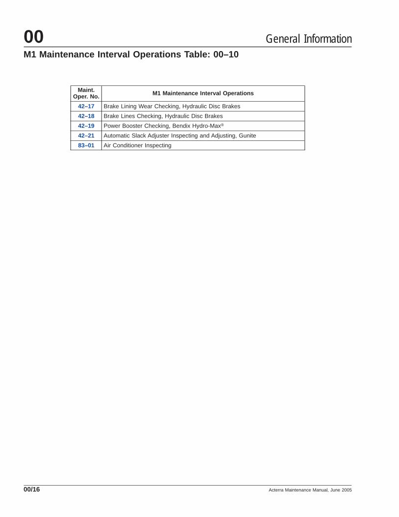
42–17 Brake Lining Wear Checking, Hydraulic Disc Brakes • • • • • •
42–18 Brake Lines Checking, Hydraulic Disc Brakes • • • • • •
42–19 Power Booster Checking, Bendix Hydro-Max® • • • • • •
General Information00Maintenance Operation Sets Tables: 00–08
Acterra Maintenance Manual, June 200500/12

Maintenance Operation Sets for Groups 33 through 42
REQUIRED MAINTENANCE OPERATION SET IM M1 M2 M3 M4 M5
Maintenance Operation Number and Operation Description
42–20 Automatic Slack Adjuster Lubricating, Gunite • • • • • •
42–21 Automatic Slack Adjuster Inspecting and Adjusting, Gunite • • • • • •
42–22 Automatic Slack Adjuster Lubricating, Haldex • • • • • •
42–23 Bosch Rail-Slide Hydraulic Brake Caliper Lubricating • • • •
Table 10, Maintenance Operation Sets for Groups 33 through 42
Maintenance Operation Sets for Groups 46 through 83
REQUIRED MAINTENANCE OPERATION SET IM M1 M2 M3 M4 M5
Maintenance Operation Number and Operation Description
46–01 Steering Driveline Lubricating • • • •
46–02 Drag Link Lubricating • • • • • •
46–03 Power Steering Reservoir Fluid Level Checking • • • •
46–04 Power Steering Reservoir Fluid and Filter Changing • •
46–05 Power Steering Gear Lubricating • • • • • •
47–01 Fuel Tank Draining and Vent Checking • • •
49–01 Exhaust System Inspecting • • • •
54–01 Electrical System Checking • • •
54–02 Coolant Level Sensor Cleaning •
72–01 Weatherstrip, Door Latch, and Door Hinge Lubricating • • • • • •
83–01 Air Conditioner Inspecting • • • • • •
83–02 HVAC Air Filter Replacing*
* Replace the HVAC filter every 6 months regardless of mileage.
Table 11, Maintenance Operation Sets for Groups 46 through 83
General Information 00Maintenance Operation Sets Tables: 00–08
Acterra Maintenance Manual, June 2005 00/13

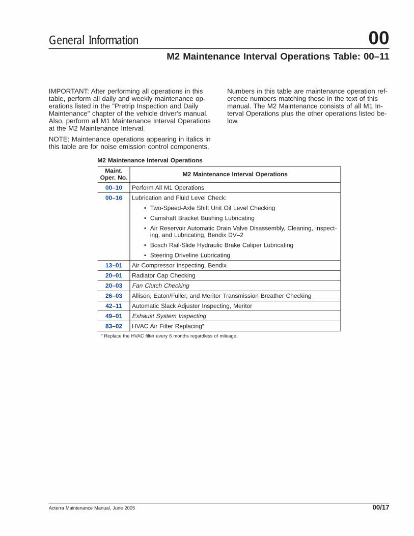
IMPORTANT: After performing all operations in thistable, perform all daily and weekly maintenance op-erations listed in the "Pretrip Inspection and DailyMaintenance" chapter of the vehicle driver’s manual.Also, perform all M1 Maintenance Interval Operationsat the Initial Maintenance (IM).
NOTE: Numbers in this table are maintenance opera-tion reference numbers matching those in the text ofthis manual. The Initial Maintenance consists of allM1 Operations plus the other operations listed below.
Initial Maintenance (IM) Operations
Maint.Oper. No. Initial Maintenance (IM) Operations
00–10 Perform All M1 Operations
25–02 Clutch (Pull-Type) Inspecting and Adjusting
26–02 Eaton Fuller and TTC Transmission Fluid Changing and Magnetic PlugCleaning*
31–01 Frame Fastener Torque Checking
32–03 U-Bolt Torque Checking
33–04 All-Axle Alignment Checking
33–07 Draw Key Nut Inspecting
35–03 Axle Lubricant Changing and Magnetic Plug Cleaning
35–04 Two-Speed-Axle Shift Unit Oil Level Checking* IM interval does not apply to vehicles with a factory fill of Eaton approved synthetic lubricant.
General Information00Initial Maintenance (IM) Operations Table: 00–09
Acterra Maintenance Manual, June 200500/14

IMPORTANT: After performing all operations in thistable, perform all daily and weekly maintenance op-erations listed in the "Pretrip Inspection and DailyMaintenance" chapter of the vehicle driver’s manual.
NOTE: Numbers in this table are maintenance opera-tion reference numbers matching those in the text ofthis manual.
M1 Maintenance Interval Operations
Maint.Oper. No. M1 Maintenance Interval Operations
00–15 Lubrication and Fluid Level Check:
• Clutch Release Bearing and Release Cross-Shaft Lubricating
• Hydraulic Fluid Level Checking
• Manual Transmission Fluid Level Checking
• Fifth Wheel Lubricating
• Suspension Lubricating
• Knuckle Pin Lubricating
• Tie-Rod End Lubricating
• All-Wheel-Drive Front Axle Oil Level Checking
• Axle Lubricant Level Checking
• Driveline Lubricating
• Foot Brake Valve Actuator Lubricating, Bendix E–8P
• Automatic Slack Adjuster Lubricating, Meritor
• Automatic Slack Adjuster Lubricating, Gunite
• Automatic Slack Adjuster Lubricating, Haldex
• Drag Link Lubricating
• Power Steering Reservoir Fluid Level Checking
• Power Steering Gear Lubricating (Ross TAS Series)
• Weatherstrip, Door Latch, and Door Hinge Lubricating
31–02 Fifth Wheel Inspecting
32–01 Suspension Inspecting
33–02 Tie-Rod End Inspecting
35–02 Axle Breather Checking
41–01 Driveline Inspecting
42–01 Air Dryer Inspecting, Bendix AD–9
42–02 Air Brake Valve Inspecting and Leak Checking, Bendix BP–R1
42–04 Air Brake Valve Operation Checking
42–05 Relay Valve Checking, Midland
42–06 Quick Release and Flipper Valves Checking, Midland
42–07 Brake Chamber Inspecting (All Models)
42–09 Automatic Slack Adjuster Checking, Meritor
42–14 Air Brake Valve Leak Checking, Bendix TC–6
General Information 00M1 Maintenance Interval Operations Table: 00–10
Acterra Maintenance Manual, June 2005 00/15
Maint.Oper. No. M1 Maintenance Interval Operations
42–17 Brake Lining Wear Checking, Hydraulic Disc Brakes
42–18 Brake Lines Checking, Hydraulic Disc Brakes
42–19 Power Booster Checking, Bendix Hydro-Max®
42–21 Automatic Slack Adjuster Inspecting and Adjusting, Gunite
83–01 Air Conditioner Inspecting
General Information00M1 Maintenance Interval Operations Table: 00–10
Acterra Maintenance Manual, June 200500/16
IMPORTANT: After performing all operations in thistable, perform all daily and weekly maintenance op-erations listed in the "Pretrip Inspection and DailyMaintenance" chapter of the vehicle driver’s manual.Also, perform all M1 Maintenance Interval Operationsat the M2 Maintenance Interval.
NOTE: Maintenance operations appearing in italics inthis table are for noise emission control components.
Numbers in this table are maintenance operation ref-erence numbers matching those in the text of thismanual. The M2 Maintenance consists of all M1 In-terval Operations plus the other operations listed be-low.
M2 Maintenance Interval Operations
Maint.Oper. No. M2 Maintenance Interval Operations
00–10 Perform All M1 Operations
00–16 Lubrication and Fluid Level Check:
• Two-Speed-Axle Shift Unit Oil Level Checking
• Camshaft Bracket Bushing Lubricating
• Air Reservoir Automatic Drain Valve Disassembly, Cleaning, Inspect-ing, and Lubricating, Bendix DV–2
• Bosch Rail-Slide Hydraulic Brake Caliper Lubricating
• Steering Driveline Lubricating
13–01 Air Compressor Inspecting, Bendix
20–01 Radiator Cap Checking
20–03 Fan Clutch Checking
26–03 Allison, Eaton/Fuller, and Meritor Transmission Breather Checking
42–11 Automatic Slack Adjuster Inspecting, Meritor
49–01 Exhaust System Inspecting
83–02 HVAC Air Filter Replacing*
* Replace the HVAC filter every 6 months regardless of mileage.
General Information 00M2 Maintenance Interval Operations Table: 00–11
Acterra Maintenance Manual, June 2005 00/17

IMPORTANT: After performing all operations in thistable, perform all daily and weekly maintenance op-erations listed in the "Pretrip Inspection and DailyMaintenance" chapter of the vehicle driver’s manual.Also, perform all M1 and M2 Maintenance IntervalOperations at the M3 Maintenance Interval.
NOTE: Numbers in this table are maintenance opera-tion reference numbers matching those in the text ofthis manual. The M3 Maintenance consists of all M1and M2 Interval Operations plus the other operationslisted below.
M3 Maintenance Interval Operations
Maint.Oper. No. M3 Maintenance Interval Operations
00–10 Perform All M1 Operations
00–11 Perform All M2 Operations
01–02 Engine Drive Belt Inspecting
09–01 Air Cleaner Element Inspecting and Replacing
25–02 Clutch (Pull-Type) Inspecting and Adjusting
26–04 Allison Transmission Fluid and Filter Changing
32–03 U-Bolt Torque Checking
33–06 All-Wheel-Drive Front Axle Oil Changing
33–07 Draw Key Nut Inspecting
35–05 Two-Speed-Axle Shift Unit Oil Changing
40–01 Wheel Nut Checking
42–12 Air Dryer Checking, Bendix AD–9
47–01 Fuel Tank Draining and Vent Checking
54–01 Electrical System Checking
General Information00M3 Maintenance Interval Operations Table: 00–12
Acterra Maintenance Manual, June 200500/18

IMPORTANT: After performing all operations in thistable, perform all daily and weekly maintenance op-erations listed in the "Pretrip Inspection and DailyMaintenance" chapter of the vehicle driver’s manual.Also, perform all M1, M2, and M3 Maintenance Inter-val Operations at the M4 Maintenance Interval.
NOTE: Maintenance operations appearing in italics inthis table are for noise emission control components.
Numbers in this table are maintenance operation ref-erence numbers matching those in the text of thismanual. The M4 Maintenance consists of all M1, M2,and M3 Interval Operations plus the other operationslisted below.
M4 Maintenance Interval Operations
Maint.Oper. No. M4 Maintenance Interval Operations
00–10 Perform All M1 Operations
00–11 Perform All M2 Operations
00–12 Perform All M3 Operations
01–01 Engine-Support Fasteners Checking
15–01 Alternator, Battery, and Starter Checking
20–02 Radiator Pressure Flushing and Coolant Changing
26–02 Eaton Fuller and TTC Transmission Fluid Changing and Magnetic PlugCleaning
31–01 Frame Fastener Torque Checking
33–04 All-Axle Alignment Checking
35–03 Axle Lubricant Changing and Magnetic Plug Cleaning
46–04 Power Steering Reservoir Fluid and Filter Changing
General Information 00M4 Maintenance Interval Operations Table: 00–13
Acterra Maintenance Manual, June 2005 00/19

IMPORTANT: After performing all operations in thistable, perform all daily and weekly maintenance op-erations listed in the "Pretrip Inspection and DailyMaintenance" chapter of the vehicle driver’s manual.Also, perform all M1, M2, M3, and M4 MaintenanceInterval Operations at the M5 Maintenance Interval.
NOTE: Numbers in this table are maintenance opera-tion reference numbers matching those in the text ofthis manual. The M5 Maintenance consists of all M1,M2, M3, and M4 Interval Operations plus the otheroperations listed below.
M5 Maintenance Interval Operations
Maint.Oper. No. M5 Maintenance Interval Operations
00–10 Perform All M1 Operations
00–11 Perform All M2 Operations
00–12 Perform All M3 Operations
00–13 Perform All M4 Operations
13–02 Air Compressor Rebuilding/Replacing, Bendix
25–04 Hydraulic Fluid Replacing
26–05 Mercedes-Benz Transmission Fluid Changing and Magnetic Plug Cleaning
26–06 Mercedes-Benz Transmission Leak Checking
42–13 Air Dryer Desiccant Replacing, Bendix AD–9
42–16 Air Brake Valve Disassembly, Cleaning, and Inspecting, Bendix E–8P,R–12, R–14, SR–1, ST–3, TC–6, and TP–3DC
54–02 Coolant Level Sensor Cleaning
General Information00M5 Maintenance Interval Operations Table: 00–14
Acterra Maintenance Manual, June 200500/20

Maintenance Operation 00–15 (see Table 12 ), sum-marizes all Lubrication and Fluid Level Check opera-tions that must be performed at the M1 MaintenanceInterval for Schedules I, II, and III
Maintenance operation numbers given in the tableare reference numbers used to help you find detailedinstructions in the manual on the lubrication or fluidcheck.
Maintenance Operation 00–15M1 Lubrication and Fluid Level Check
Maint.Oper. No. Operation Description
25–01 Clutch Release Bearing and Release Cross-Shaft Lubricating
25–03 Hydraulic Fluid Level Checking
26–01 Manual Transmission Fluid Level Checking
31–03 Fifth Wheel Lubricating
32–02 Suspension Lubricating
33–01 Knuckle Pin Lubricating
33–03 Tie-Rod End Lubricating
33–05 All-Wheel-Drive Front Axle Oil Level Checking
35–01 Axle Lubricant Level Checking
41–02 Driveline Lubricating
42–03 Foot Brake Valve Actuator Lubricating, Bendix E–8P
42–10 Automatic Slack Adjuster Lubricating, Meritor
42–20 Automatic Slack Adjuster Lubricating, Gunite
42–22 Automatic Slack Adjuster Lubricating, Haldex
46–02 Drag Link Lubricating
46–03 Power Steering Reservoir Fluid Level Checking
46–05 Power Steering Gear Lubricating
72–01 Weatherstrip, Door Latch, and Door Hinge Lubricating
Table 12, Maintenance Operation 00-15, M1 Lubrication and Fluid Level Check
General Information 00Lubrication and Fluid Level Check (M1): 00–15
Acterra Maintenance Manual, June 2005 00/21

Maintenance Operation 00–16 (see Table 13 ), sum-marizes all Lubrication and Fluid Level Check opera-tions that must be performed at the M2 MaintenanceInterval for Schedules I, II, and III
Maintenance operation numbers given in the tableare reference numbers used to help you find detailedinstructions in the manual on the lubrication or fluidcheck.
Maintenance Operation 00–16M2 Lubrication and Fluid Level Check
Maint.Oper. No. Operation Description
35–04 Two-Speed-Axle Shift Unit Oil Level Checking
42–08 Camshaft Bracket Bushing Lubricating
42–15 Air Reservoir Automatic Drain Valve Disassembly, Cleaning, Inspecting,and Lubricating, Bendix DV–2
42–23 Bosch Rail-Slide Hydraulic Brake Caliper Lubricating
46–01 Steering Driveline Lubricating
Table 13, Maintenance Operation 00-16, M2 Lubrication and Fluid Level Check
General Information00Lubrication and Fluid Level Check (M2): 00–16
Acterra Maintenance Manual, June 200500/22

Title of Maintenance Operation (MOP) MOP Number
Engine Drive Belt Inspecting. . . . . . . . . . . . . . . . . . . . . . . . . . . . . . . . . . . . . . . . . . . . . . . . . . . . . . . . . . 01–02
Engine-Support Fasteners Checking. . . . . . . . . . . . . . . . . . . . . . . . . . . . . . . . . . . . . . . . . . . . . . . . . . . . 01–01
Pacbrake Inspecting and Maintenance . . . . . . . . . . . . . . . . . . . . . . . . . . . . . . . . . . . . . . . . . . . . . . . . . . 01–03
Engine 01Index, Alphabetical
Acterra Maintenance Manual, March 2000

01–01 Engine-SupportFasteners Checking
Check the rear engine-support fasteners (see Fig. 1 ,Ref. 4) for tightness. Tighten the 3/4-inch fasteners215 to 265 lbf·ft (292 to 359 N·m).
Check the front engine-support fasteners for tight-ness. Tighten the 5/8-inch fasteners 125 lbf·ft (170N·m).
NOTE: At engine overhaul, and whenever theengine has been removed, inspect the lowerand upper isolators (Refs. 1 and 6), and replacethem if they are worn. See Group 01 of the Ac-terra® Workshop Manual for instructions.
01–02 Engine Drive BeltInspecting
Worn or loose drive belts may cause prematurebearing failure or engine overheating. Excessive ten-sion, or too little tension on the belt may result in ex-cessive and premature belt wear. Poly-V belts, orserpentine belts, are retained by a belt tensioner thatrequires no tension adjustment. Replace the enginedrive belt if any conditions described in the visualdescription are found. V-belts are installed as indi-vidual belts, and as matched sets. When replacing a
matched set of belts, always replace both belts at thesame time. Matched belts must be from the samemanufacturer. To inspect a belt, gently twist the beltto view the belt sidewalls and bottom. Inspect alldrive belts for the following conditions, then performthe belt tension inspection.
Belt Condition Inspection1. Inspect the belt for glazing. See Fig. 2 , Ref. A.
Glazing is represented by shiny sidewalls, and iscaused by friction created when a loose belt slipsin the pulleys. It can also be caused by oil orgrease contamination on the pulleys.
2. Check the belt for ply separation. See Fig. 2 ,Ref. B. Oil, grease, or belt dressing can causethe belt to fall apart in layers. Repair any oil orcoolant leaks that are affecting the belts beforereplacing the drive belts. Do not use belt dress-ing on any belt.
3. Check the belt for a jagged or streaked sidewall.See Fig. 2 , Ref. C. Jagged or streaked sidewallsare the result of foreign objects, such as sand orgravel in the pulley, or a rough pulley surface.
4. Check for tensile breaks (breaks in the cordbody). See Fig. 2 , Ref. D. Cuts in a belt are usu-ally caused by foreign objects in the pulley, or byprying or forcing the belt during removal or instal-lation.
5. Check for uneven ribs on serpentine (poly-V)belts. See Fig. 2 , Ref. E. Foreign objects in thepulley will erode the undercord ribs, causing thebelt to lose its gripping power.
6. Check the drive belts for cracks. See Fig. 2 , Ref.F. Small irregular cracks are usually the signs ofan old belt.
7. Inspect the pulleys for excessive play or wobble.Excessive play or wobble indicates a failure ofthe pulley bearing. Check for belt squealing orsqueaking. Replace the bearings as necessary.
NOTE: If it is difficult to distinguish the locationof a supposed bearing noise, obtain a stetho-scope and place it on the component beingchecked, not the pulley, to isolate the area fromoutside interference.
8. Inspect all pulleys for foreign objects, oil, orgrease in the grooves.
f220047a
1
2 3 4 5
6
2
10/05/94
1. Lower Isolator2. Engine Support
Washer3. 3/4–10 Capscrew
4. 3/4–10 Hexnut5. Engine Mount6. Upper Isolator
Fig. 1, Engine Rear Mount
Engine 01
Acterra Maintenance Manual, March 2000 01/1

Belt Tension InspectionNOTE: If engine drive belts require adjustment,see Group 01 of the Acterra® Workshop Manualfor instructions.
Threaded-Adjustment Type1. Apply the parking brakes, and chock the tires to
prevent the vehicle from moving.
2. Install a belt tension gauge at the center of thebelt’s longest free-span. Check belt tension. SeeTable 1 for belt tension specifications.
3. If belt tension is not correct, see Group 01 of theActerra® Workshop Manual to adjust belt tension.
Spring-Tension TypeOn belts equipped with a spring tensioner, the belttension is automatically adjusted. Check that the ten-sioner is holding tension on the belt by inserting the
end of a breaker bar in the 1/2-inch square hole onthe forward face of the tensioner, and rotating thetensioner down, away from the belt. When thebreaker bar is slowly released, the tensioner shouldreturn to its original position. If not, see Group 01 ofthe Acterra® Workshop Manual for replacementinstructions.
NOTE: Caterpillar engines are provided withautomatic drive belt tensioners. The followingengines, which appear in Table 1 , are providedwith automatic tensioners for the fan and alter-nator belts.
f150010a
A
B
C
D
E
F11/21/94
A. GlazingB. Separating LayersC. Streaked Sidewalls
D. Tensile BreakE. Uneven RibsF. Cracks
Fig. 2, Drive Belt Replacement Conditions
Engine01
Acterra Maintenance Manual, March 200001/2

Engine Component Belt Tension:lbf (kg)
Cummins ISB, ISC, ISM Refrigerant Compressor 100 (45)
Mercedes-Benz MBE900Fan and Alternator 29.5 (27.9)
Refrigerant Compressor 30.0 (28.4)
Table 1, Drive Belt Tensions
01–03 Pacbrake Inspecting andMaintenance
With frequent use, the Pacbrake Exhaust Brake willoperate maintenance-free. If the vehicle is used in-consistently or seasonally, it will be necessary to per-form preventative maintenance. If the vehicle is ex-posed to excess moisture, or is used only forperiodical or seasonal use, perform the followingsteps:
1. With the engine off, use any oil-free or non-petroleum based high-heat lubricant, and sprayor coat a sufficient amount on the restricter valveshaft and the attaching locations at each end ofthe actuation cylinder.
2. With your hands or a pair of pliers, motion thevalve several times to distribute the lubricantdown the shaft and the attaching locations.
NOTE: Operation of the Pacbrake could be af-fected by starting the engine and idling for shortperiods of time. During a cold engine start-up,moisture occurs in the engine and the exhaustsystem that creates a corrosion hazard. Thebrake housing may trap water in the valve shaftbore causing corrosion resulting in an improperor non-functioning brake. If it is necessary toperiodically start the engine, attain normal oper-ating temperatures before shutting down the en-gine.
Engine 01
Acterra Maintenance Manual, March 2000 01/3

Title of Maintenance Operation (MOP) MOP Number
Air Cleaner Element Inspecting and Replacing . . . . . . . . . . . . . . . . . . . . . . . . . . . . . . . . . . . . . . . . . . . . 09–01
Air Intake 09Index, Alphabetical
Acterra Maintenance Manual, February 2004

09–01 Air Cleaner ElementInspecting andReplacing
Method 1Replace the air cleaner element at the recommendedinterval or when the air restriction indicator reaches22 inH2O on a vehicle with an MBE engine, or 25inH2O on a vehicle with a Caterpillar or Cumminsengine, if equipped with an air restriction indicator.For replacement instructions, see Group 09 of theActerra® Workshop Manual. Reset the air restrictionindicator.
If the maximum restriction is not reached, record theair restriction value. If the value is higher than theprevious recording, reset the air restriction indicator.If the value is lower than the previous recording, in-spect the air cleaner and air cleaner element ofcracks, leaks, or any other damage.
If the air cleaner or air cleaner element is damaged,replace it and reset the air restriction indicator.
Method 2Replace the air cleaner element at the recommendedinterval or when the air restriction indicator reaches22 inH2O on a vehicle with an MBE engine, or 25inH2O on a vehicle with a Caterpillar or Cumminsengine, if equipped with an air restriction indicator.For replacement instructions, see Group 09 of theActerra® Workshop Manual. Reset the air restrictionindicator.
If the maximum restriction is not reached, inspect theair cleaner and air cleaner element for cracks, leaks,or any other damage. If the air cleaner or air cleanerelement is damaged, replace it and reset the air re-striction indicator.
Air Intake 09
Acterra Maintenance Manual, February 2004 09/1

Title of Maintenance Operation (MOP) MOP Number
Air Compressor Inspecting, Bendix . . . . . . . . . . . . . . . . . . . . . . . . . . . . . . . . . . . . . . . . . . . . . . . . . . . . . 13–01
Air Compressor Rebuilding/Replacing, Bendix. . . . . . . . . . . . . . . . . . . . . . . . . . . . . . . . . . . . . . . . . . . . . 13–02
Air Compressor 13Index, Alphabetical
Acterra Maintenance Manual, March 2000

13–01 Air CompressorInspecting, Bendix
Inspect the air intake line, oil supply and return lines,and coolant supply and return hoses for tight connec-tions and general condition. Tighten the connections,and replace the lines and hoses, as needed. If thecompressor air-intake adapter is loose, remove theadapter, replace its gaskets, and securely install it.
Check the cooling fins on the compressor crankcase.Clean the fins if they are clogged with debris.
13–02 Air CompressorRebuilding/Replacing,Bendix
Disassemble, clean, and inspect the air compressor.Replace all seals, gaskets, springs, and all parts thatare worn or damaged beyond re-use. Replace the aircompressor unloader mechanism components. Useonly genuine Bendix replacement parts or kits. Testthe operation of the unloader mechanism. SeeGroup 13 of the Acterra® Workshop Manual for re-build (or replacement) instructions and test opera-tions.
NOTE: Bendix factory-rebuilt air compressorsare available from authorized Bendix distribu-tors, and carry a new compressor warranty.
Air Compressor 13
Acterra Maintenance Manual, March 2000 13/1

Title of Maintenance Operation (MOP) MOP Number
Alternator, Battery, and Starter Checking. . . . . . . . . . . . . . . . . . . . . . . . . . . . . . . . . . . . . . . . . . . . . . . . . 15–01
Alternators and Starters 15Index, Alphabetical
Acterra Maintenance Manual, March 2000

15–01 Alternator, Battery, andStarter Checking
WARNINGBatteries release a gas mixture that is explosive.Do not smoke when working around batteries. Putout all flames and remove any source of sparks orintense heat. Make sure the battery compartmenthas been completely vented before disconnectingor connecting the battery cables.
Battery acid is extremely harmful if splashed inthe eyes or on the skin. Always wear a face shieldand protective clothing when working aroundbatteries.
1. Check the tightness of the alternator bracket fas-teners; tighten the fasteners as needed. Fortorque values, see Group 15 of the Acterra®
Workshop Manual for instructions.
2. Check the belt tension of the alternator drivebelt. Use a tension gauge at the belt’s widestspan, and adjust the belt tension if needed. SeeGroup 01 of this manual for belt tension specifi-cations. Some Caterpillar engines are equippedwith dual alternator belts. Always check bothbelts for correct tension. Check that the tensioneroperates smoothly without binding. Enginesequipped with a serpentine, or poly-V belt haveautomatic belt tensioners and do not require belttension inspection.
3. Check that all electrical connections at the alter-nator and starter are clean. Clean and tighten allcharging system electrical connections asneeded.
4. Inspect the battery cables for wear, and replaceas needed. Clean the cable connector terminalswith a wire brush. See Group 54 of the Acterra®
Workshop Manual for troubleshooting instruc-tions, and for adjustment, repair, or replacementinstructions.
4.1 Clean and tighten the battery groundcable, terminal, and clamps.
4.2 Inspect the retainer assembly (or batteryhold-downs) and the battery box. Replaceworn or damaged parts. Remove any cor-rosion with a wire brush, and wash with aweak solution of baking soda and water.
Rinse with clean water, and dry. Paint theretainer assembly, if needed, to preventrusting.
4.3 Check that foreign objects, such asstones, bolts, and nuts are removed fromthe battery box.
4.4 After cleaning, connect the cables to thebatteries, and tighten them to the torquespecifications listed on the battery, gener-ally 10 to 15 lbf·ft (14 to 20 N·m).
4.5 Spray each connection with dielectric redenamel and coat the battery terminalswith dielectric grease; see Table 1 .
Protectant Material Approved Brand
Dielectric Grease Lubriplate FLP DS–ES
Dielectric Red EnamelSpray
3M 1602 IVI-Spray Sealer
Spray-On B–6–665
Table 1, Approved Dielectric Protectants
5. Check the alternator wiring for missing insulation,kinks, and heat damage. Replace or repair asneeded.
6. Check the terminals on the battery shut-offswitch and the magnetic switch. Make sure theterminal connections are clean and tight. Coatthe terminal connections with dielectric redenamel after cleaning; see Table 1 .
Alternator and Starter 15
Acterra Maintenance Manual, March 2000 15/1

Title of Maintenance Operation (MOP) MOP Number
Fan Clutch Checking (Noise Emission Control) . . . . . . . . . . . . . . . . . . . . . . . . . . . . . . . . . . . . . . . . . . . . 20–03
Radiator Cap Checking. . . . . . . . . . . . . . . . . . . . . . . . . . . . . . . . . . . . . . . . . . . . . . . . . . . . . . . . . . . . . . 20–01
Radiator Pressure Flushing and Coolant Changing . . . . . . . . . . . . . . . . . . . . . . . . . . . . . . . . . . . . . . . . . 20–02
Engine Cooling/Radiator 20Index, Alphabetical
Acterra Maintenance Manual, October 2002

20–01 Radiator Cap Checking
WARNINGDo not remove or loosen the radiator cap until theengine and cooling system have completelycooled. Use extreme care when removing the cap.A sudden release of pressure from removing thecap prior to the system cooling can result in asurge of scalding coolant that could cause seri-ous personal injury.
CAUTIONThe radiator cap currently installed may not be thesame one installed when the vehicle was built. Ifthe radiator cap must be replaced, make sure thatit is the correct cap for the cooling system of thevehicle. Because the radiator cap pressure ratingaffects the operating temperature of the engine,installing an improperly rated radiator cap mayhave adverse effects on the cooling system, andengine operating temperatures. This could causepremature engine wear or damage.
1. Using a radiator-cap tester, check the pressurecap to see if it maintains pressure to within 10%of the pressure rating marked on the cap. If itdoesn’t, replace the cap. Make sure that the re-placement radiator cap is correctly rated for thecooling system of the vehicle.
2. There is a second valve in the radiator cap thatopens under vacuum. This prevents the collapseof hoses and other parts that are not internallysupported when the system cools. Inspect thevacuum-relief valve to be sure it is not stuck.
3. Make sure that the cap seals properly on thecoolant filler neck seat, and that the radiator capgasket is not damaged. On vehicles with screwon caps with O-rings, make sure that the O-ringis not cracked or deteriorated. Replace the cap ifthe gasket shows deterioration or damage.
20–02 Radiator PressureFlushing and CoolantChanging
NOTE: For additional instructions on cleaningand flushing the cooling system, see the enginemanufacturer’s maintenance and operationmanual.
1. Drain the radiator.
1.1 Remove the surge tank cap. See Fig. 1 .
1.2 Open the petcock at the bottom of theradiator to drain the engine coolant. SeeFig. 2 .
2. Disconnect the radiator inlet and outlet hose con-nections.
3. Flush the radiator.
3.1 Attach a flushing gun nozzle to the radia-tor outlet.
3.2 Run water in until the radiator is full.
3.3 Apply no more than 20 psi (138 kPa) airpressure intermittently to help dislodgesediment buildup in the core.
f500107a
1
11/19/94
1. Surge Tank
Fig. 1, Surge Tank and Cap
Engine Cooling/Radiator 20
Acterra Maintenance Manual, October 2002 20/1

CAUTIONWhen flushing the radiator, do not apply morethan 20 psi (138 kPa) air pressure. Excessive pres-sure can damage the radiator or heater core.
4. Drain the radiator, and flush the radiator untilclean water flows from the radiator. Remove theflushing gun.
5. Close the petcock at the bottom of the radiator.
6. Connect the hoses. Your hose clamps can beeither T-bolt clamps (see Fig. 3 ) or BreezeConstant-Torque clamps (see Fig. 4 ).
Tighten T-bolt type hose clamps 55 lbf·in (620N·cm). These clamps are now standard on hoseswith an inside diameter greater than 2 inches (51mm).
Breeze Constant-Torque hose clamps must betightened to the correct torque. The screw tip ofthe clamp must extend about 1/4 inch (6 mm)from the clamp housing, and the bellevillewasher stacks must be collapsed almost flat.Use a torque wrench to install these clamps.Correct installation torque is as follows:
For Breeze Constant-Torque hose clamps with a5/16-inch tightening screw hex: 55 lbf·in (620N·cm).
For Breeze Constant-Torque hose clamps with a3/8-inch tightening screw hex: 90 lbf·in (1020N·cm).
NOTE: All hose clamps will lose torque afterinstallation due to "compression set." However,when correctly installed, Breeze Constant-Torque clamps will hold enough torque to auto-matically adjust and keep consistent sealingpressure. During vehicle operation and shut-down, the screw tip may adjust according to
f500108a
1
2
11/19/94
1. Radiator 2. Horn
Fig. 2, Draining The Engine Coolant
02/28/96 f200326
Fig. 3, T-Bolt Type Hose Clamp
08/15/94 f200286
A B1
A. The screw tip must extend about 1/4 inch (6 mm).B. The belleville washer stacks must be collapsed
almost flat.1. Tightening Screw Hex
Fig. 4, Breeze Constant-Torque Hose Clamp Installation
Engine Cooling/Radiator20
Acterra Maintenance Manual, October 200220/2

temperature and pressure changes. The torquemay need to be adjusted for individual applica-tions.
7. Fill the radiator with coolant.
Use a mixture of 50 percent water and 50 per-cent corrosion-inhibiting antifreeze to protect theengine to –34°F (–37°C) year round.
See Table 1 for engine cooling system capaci-ties.
See Table 2 for approved antifreezes.
Coolant Capacities
Engine Make andModel
Radiator Coreand System Capacity *
2 Rowquarts (liters)
3 Rowquarts (liters)
Caterpillar 3126Series
28 (26.5) —
Cummins B Series 30.5 (28.9) 31.0 (29.3)
Cummins C Seriesand M11 31.2 (29.5) —
* System capacity includes all hoses, fittings, and the heater core.
Table 1, Coolant Capacities
Approved Coolants
Engine Type CoolantManufacturer
CoolantDesignation *
Diesel Texaco JC04 Antifreeze
Van Waters andRogers Ltd.(Canada)
Diesel AntifreezeNo. 6038
Gasoline Chrysler Mopar* Sterling-approved antifreeze must meet one of the following conditions: A.
Ethylene glycol solution that meets GM 6038–M Engineering Standards. B.Ethylene glycol solution that has less than 0.1% anhydrous sodium metasili-cate, and meets either GM 1825–M or GM 1899–M Engineering Standards.
Table 2, Approved Coolants
NOTE: You can mix purple-pink coolant (pre-charged with a borate/nitrate-based additive)with the common green coolant, although somecolor change will be apparent.
20–03 Fan Clutch Checking(Noise EmissionControl)
Eaton Viscous Fan Clutch
CAUTIONIf the fan drive assembly is damaged, replace theunit as soon as possible. Operating a seized orotherwise damaged clutch reduces fuel economy,and could cause serious engine damage.
See Group 20 of the Acterra® Workshop Manual forreplacement instructions.
1. With the engine off, rotate the fan at least onefull turn by hand. It should have a smooth,steady drag. If it does not, replace the fan clutch.
2. Check for physical damage to the fan or fanshroud.
3. At the fan clutch mounting:
3.1 Check for correct drive belt alignment andtension. For specifications, see Group 01of this manual.
3.2 Check for wear of the fan clutch bearings.There should be no side-to-side or in-and-out movement of the fan clutch.
3.3 Do all of the checks in Section 20.02 ofthe Acterra® Workshop Manual.
Horton Advantage® Fan ClutchNOTE: If any part of the fan clutch needs to berepaired or replaced after performing the checksbelow, see Group 20 of the Acterra® WorkshopManual.
1. Disconnect the the batteries at the negative ter-minals. Drain all air from the air system. Ifequipped with an air starter, drain the air starterreservoir.
WARNINGMake sure the batteries are disconnected, and ifapplicable, the air starter reservoir is drained be-fore checking the fan clutch. If the engine starts
Engine Cooling/Radiator 20
Acterra Maintenance Manual, October 2002 20/3

during this procedure, the fan could engage,which could result in serious personal injury.
2. Inspect the electrical connections and wires tothe fan clutch solenoid. Secure the connection, ifloose; replace wires and connectors if damaged.
3. Clean the fan clutch air solenoid valve filter, ifequipped.
3.1 Unscrew the fan clutch solenoid valve airfilter assembly and remove the filter ele-ment.
3.2 Clean the filter element with cleaning sol-vent.
3.3 Reassemble the clutch valve solenoid airfilter assembly and install on the vehicle.
4. Check the fan for bent, cracked, or damagedblades. Replace, if damaged. Check for ad-equate clearance between the fan and othercomponents.
5. Check the fan belt for wear, tension, and align-ment. Correct, if necessary.
6. Check for wear on the friction facing. See Fig. 5. Replace the friction facing if it is worn to a 1/16-inch (1.6-mm) thickness or less. Also check thefacing for signs of oil contamination or burnmarks. If evidence of oil or burn marks arefound, replace the friction facing.
7. Connect the battery cables. Start the engine, andcharge the air system to 120 psi (827 kPa). Shut
down the engine. Separate the halves of the fansolenoid connector. The fan clutch should en-gage.
If the fan does not operate correctly, see Group20 of the Acterra® Workshop Manual for trouble-shooting and repair procedures.
8. With the air system charged to 120 psi (827kPa), and with the fan solenoid connector halvesseparated, check the fan clutch for audible airleaks, using a suitable listening device.
9. If a leak is detected, remove the fan blade. Usinga soapy water solution, check the fan clutch atthe following locations to locate the source of theleak. Install a new seal kit. See Group 20 of theActerra® Workshop Manual for repair procedures.
9.1 Check for a leak at the bleed hole on thefan pilot. Air leakage means that the car-tridge assembly (see Fig. 6 , Ref. 16) orface seal (Ref. 17) is damaged.
9.2 Check for air leaks between the air cham-ber and the piston friction disc. Air leak-age means that the large O-ring (Ref. 14)is damaged.
9.3 Check for air leaks around the safeguardhole on the piston friction disc. Air leak-age means the small O-ring (Ref. 18) isdamaged.
9.4 Check for air leaking from the SystemSentry® fuse. Leaking air means theclutch has gotten so hot the lead alloy inthe fuse melted. This released the clutchbefore the heat could damage the clutchbearings. Before replacing the fuse, findand repair the source of the heat.
10. If equipped with an override toggle switch on thedash, check the fan clutch operation as follows:
10.1 Connect the halves of the fan solenoidconnector.
10.2 Turn the air conditioner off.
10.3 Start the engine and charge the air sys-tem to 120 psi (827 kPa). Tests must beperformed with the engine temperaturebelow 205°F (96°C) for Caterpillar en-gines, and below 200°F (93°C) for Cum-mins.
f200290
1
2
08/08/94
3 4
5
1. System Sentry® Fuse2. Safeguard Hole3. Friction Facing
4. Piston Friction Disc5. Air Chamber
Fig. 5, Horton Advantage Fan Clutch
Engine Cooling/Radiator20
Acterra Maintenance Manual, October 200220/4

10.4 Set the toggle switch to the ON position;the fan clutch should engage.
10.5 Apply the foot brake, and release theparking brakes.
10.6 Set the toggle switch to the AUTO or OFFposition; the air should exhaust and thefan clutch should disengage. Replace theswitch, if necessary.
Kysor K22RA Fan Clutch1. Disconnect the electrical cables from the battery.
Drain all air from the air system. If equipped withan air starter, drain the air starter reservoir.
WARNINGMake sure the batteries are disconnected, and ifapplicable, the air starter reservoir is drained be-fore checking the fan clutch. If the engine startsduring this procedure, the fan could engage,which could result in serious personal injury.
2. Measure the distance from the back surface ofthe fan clutch retaining plate to the forward-mostedge of the fan belt pulley. See Fig. 7 , Ref. A.
3. Disconnect the line from the air inlet of the aircylinder. Connect a shop air hose to the inlet.
4. Apply a minimum of 100 psi (690 kPa) air pres-sure to the air cylinder—the bearing housing willmove backwards, disengaging the clutch. Again,measure the distance from the back surface of
f200194a
1 2
34
5
67
8
910
1112
13
14 15
16
17
18
19 20
2123
22
24
03/30/95
1. Mounting Bracket2. Rear Sheave Bearing3. Inner and Outer Bearing
Spacers4. Forward Sheave Bearing5. Sheave6. Friction Facing7. Journal Spacer8. Socket-Head Capscrew
9. Rear Hub Bearing10. Bearing Spacer11. Splined Hub12. Forward Hub Bearing13. Piston Friction Disc14. Large O-Ring15. Locknut16. Cartridge Assembly
17. Face Seal18. Small O-Ring19. Air Chamber20. Socket-Head Capscrew21. Stud Bolt22. Lockwasher23. Hexnut24. Piston Assembly
Fig. 6, Horton Advantage Fan Clutch Components
Engine Cooling/Radiator 20
Acterra Maintenance Manual, October 2002 20/5

the retaining plate to the forward-most edge ofthe fan belt pulley.
5. Compare the two measurements; if the differencebetween the two measurements exceeds 0.150inches (3.8 mm), the clutch lining is worn andmust be replaced. See Group 20 of the Acterra®
Workshop Manual for clutch lining replacementinstructions.
6. Release the air pressure, then disconnect theshop hose from the air inlet of the air cylinder.Connect the vehicle air hose to the inlet.
7. Connect the electrical cables to the battery.
8. Start the engine.
Horton DriveMaster® Fan ClutchNOTE: If any part of the fan clutch needs to berepaired or replaced after performing the checksbelow, see Group 20 of the Acterra® WorkshopManual.
1. Disconnect the batteries at the negative termi-nals. Drain all air from the air system. Ifequipped with an air starter, drain the air starterreservoir.
WARNINGMake sure the batteries are disconnected, and ifapplicable, the air starter reservoir is drained be-fore checking the fan clutch. If the engine startsduring this procedure, the fan could engage,which could result in serious personal injury.
2. Inspect the electrical connections and wires tothe fan clutch solenoid. Secure the connection ifloose; replace wires and connectors if damaged.
3. Clean the fan clutch air solenoid valve filter, ifequipped.
3.1 Unscrew the fan clutch solenoid valve airfilter assembly and remove the filter ele-ment.
3.2 Clean the filter element with cleaning sol-vent.
3.3 Using a clean, lint free cloth, wipe off anyexcess solvent.
3.4 Reassemble the clutch valve solenoid airfilter assembly and install on the vehicle.
4. Visually check the fan for bent, cracked, or dam-aged blades. Replace if damaged. Check for ad-equate clearance between the fan and othercomponents.
5. Check the fan belt for wear, tension, and align-ment. Correct, if necessary.
6. Check for wear on the friction facing. Replacethe friction facing if it is worn to a 3/16-inch (4.8-mm) thickness or less. Also check the facing forsigns of oil contamination or burn marks. If evi-dence of oil or burn marks are found, replace thefriction facing.
7. Connect the battery cables. Start the engine, andcharge the air system to 120 psi (827 kPa).Manually engage and disengage the fan clutch.
Check the fan and the fan clutch from a dis-tance. Look for vibration, fan blade contact, fanclutch slippage, and overall fan clutch operation.
f200237a
1
23
4
5
6
05/27/93
A
With the fan clutch engaged, measure the distance at A;measure it again with the fan clutch disengaged.
1. Bearing Housing2. Retaining Plate3. Fan Pulley4. Air Inlet (from solenoid
valve)
5. Air Cylinder6. Fan
Fig. 7, Kysor K22RA Fan Clutch Lining Wear Checking
Engine Cooling/Radiator20
Acterra Maintenance Manual, October 200220/6

If the fan clutch does not operate correctly, seeGroup 20 of the Acterra® Workshop Manual fortroubleshooting and repair procedures.
8. With the air system charged to 120 psi (827kPa), check the fan clutch for audible air leaks,using a suitable listening device.
Check at the solenoid valve, the air filter assem-bly, and the air hoses and fittings. See Fig. 8 .Using a wet finger or a soapy water solution,check for a leak in the same areas.
9. If a leak is detected, remove the fan blade. In-stall a new seal kit. See Group 20 of the Ac-terra® Workshop Manual for repair procedures.
10. Check the fan drive for discoloration or any othersigns of slipping or overheating.
NOTE: The fan clutch may slip if the air supplypressure is below 70 psi (483 kPa) or if there isa leak inside the fan clutch. Any leak must beremedied.
11. Check the fan clutch bearings.
11.1 Turn the fan in both directions and feelfor worn hub bearings.
11.2 If possible, remove the drive belt andcheck for worn sheave bearings by turn-ing the sheave in both directions.
11.3 If either the hub or sheave bearings areworn, replace them, using a Horton Drive-Master Super Kit.
For instructions and kit part number, seeGroup 20 of the Acterra® WorkshopManual.
f20058105/30/2002
Fig. 8, Checking for Air Leaks (Horton DriveMaster)
Engine Cooling/Radiator 20
Acterra Maintenance Manual, October 2002 20/7

Title of Maintenance Operation (MOP) MOP Number
Clutch (Pull-Type) Inspecting and Adjusting. . . . . . . . . . . . . . . . . . . . . . . . . . . . . . . . . . . . . . . . . . . . . . . 25–02
Clutch Release Bearing and Release Cross-Shaft Lubricating . . . . . . . . . . . . . . . . . . . . . . . . . . . . . . . . . 25–01
Hydraulic Fluid Level Checking. . . . . . . . . . . . . . . . . . . . . . . . . . . . . . . . . . . . . . . . . . . . . . . . . . . . . . . . 25–03
Hydraulic Fluid Replacing. . . . . . . . . . . . . . . . . . . . . . . . . . . . . . . . . . . . . . . . . . . . . . . . . . . . . . . . . . . . 25–04
Clutch 25Index, Alphabetical
Acterra Maintenance Manual, September 2002

25–01 Clutch Release Bearingand Release Cross-ShaftLubricating
Clutch Release Bearing
CAUTIONDo not over-lubricate the clutch release bearing.Over-lubrication could contaminate the clutch in-ternally, causing clutch slippage and prematurefailure. Do not use chassis grease or multipurposelubricants.
On clutches with a grease-type release bearing (seeFig. 1 ), wipe the dirt from the grease fitting. Using apressure gun and high-temperature grease only, lu-bricate the release bearing at the grease fitting untilthe grease starts coming out of the fitting. Use only alithium-based grease that meets NLGI grade 1 or 2specifications.
NOTE: On clutches with a sealed release bear-ing, the release bearing is lubricated at the timeof manufacture and requires no additionalgrease for the life of the bearing.
On Sachs hydraulic clutches, never lubricate therelease bearing. The release bearing is made ofplastic with a kind of embedded grease.
Clutch Release Cross-ShaftThe clutch release cross-shaft is equipped with twogrease fittings; one at each side of the transmissionclutch housing. Wipe the dirt from the grease fittings.Using a pressure gun, lubricate the cross-shaft withmultipurpose chassis grease.
25–02 Clutch (Pull-Type)Inspecting andAdjusting
See Group 25 of the Acterra® Workshop Manual forclutch (pull-type) inspection and adjustment.
25–03 Hydraulic Fluid LevelChecking
WARNINGUse only approved clutch hydraulic fluid (DOT 3brake fluid) in the clutch hydraulic system. Do notmix different types of brake fluid. The wrong fluidwill damage the rubber parts of the system, caus-ing loss of clutch function and the risk of seriouspersonal injury.
CAUTIONDo not allow the fluid level in the reservoir to gobelow the MIN line. If too much air enters, the hy-draulic system will not operate correctly, and theclutch could be damaged.
If the fluid level is below the MIN mark, fill the reser-voir with DOT 3 brake fluid until the level reaches theMAX mark. See Fig. 2 .
25–04 Hydraulic FluidReplacing
Replace the clutch hydraulic fluid every two years toensure clutch function is reliable and correct. Use the
f250081a05/27/93
Fig. 1, Release Bearing Grease Fitting
Clutch 25
Acterra Maintenance Manual, September 2002 25/1

procedures below. Fluid replacement must be doneat an authorized Freightliner service facility.
Draining and Filling1. Shut down the engine.
2. Apply the parking brakes, chock the front andrear tires, and open the hood.
3. Using a flat-tip screwdriver, remove the quick-disconnect clamp that attaches the hydraulichose to the slave cylinder. Retain the clamp forlater installation. See Fig. 3 .
WARNINGClutch hydraulic fluid (DOT 3 brake fluid) is haz-ardous. It may be a skin irritant and can causeblindness if it gets in your eyes. Always wearsafety glasses when handling clutch hydraulicfluid or bleeding hydraulic lines. If you get clutchhydraulic fluid on your skin, wash it off as soonas possible.
4. Drain the hydraulic fluid.
4.1 Using a drain pan or other suitable con-tainer, collect the fluid that drains from thereservoir, not more than 0.3 quarts (0.3liters).
4.2 Allow the open end of the drain hose toremain over the drain pan.
06/17/2002 f250588
1
2
3
4
5
7
6
1. Reservoir2. Reservoir Cap3. Pedal Unit4. Master Cylinder
5. Hydraulic Hose6. Slave Cylinder7. Reservoir Hose
Fig. 2, Clutch Components
06/17/2002 f250589
12
3 4
5
6
78
9
10
1. Clamp Mounting Bolt, 1/4–202. Steel-Plated Flatwasher3. Locknut, 1/4–204. Bell Housing Standoff Bracket5. Hydraulic Hose6. Bleed Valve7. Slave Cylinder8. Slave Cylinder Capscrew, M89. Flatwasher, M810. Cushioned Clamp
Fig. 3, Clutch Slave Cylinder
Clutch25
Acterra Maintenance Manual, September 200225/2

4.3 Press down on the pedal several times,until no more fluid drains from the reser-voir.
4.4 Cover the hose to avoid contamination ofthe clutch hydraulic fluid.
5. Connect the hydraulic hose to the slave cylinder.Install the clamp, as removed.
6. Fill the reservoir with approved DOT 3 brake fluidand bleed the system according to the proce-dures under the heading "Bleeding the Clutch."See Fig. 4 .
Bleeding the Clutch1. Apply the parking brake and chock the tires.
2. Prepare the pressure bleeding equipment ac-cording to the manufacturer’s instructions. UseDOT 3 brake fluid. Pressurize the bleeder unit to15 psi (103 kPa).
CAUTIONDo not spill clutch hydraulic fluid (DOT 3 brakefluid) on the cab paint. Clean it off immediately ifany is spilled. DOT 3 brake fluid can damagepaint.
3. Remove the reservoir lid and install the pressurebleed adaptor on the reservoir.
4. Remove the cap from the bleed valve. Install atransparent drain hose on the bleed valve of theslave cylinder.
IMPORTANT: The slave cylinder may not bemounted in a horizontal position. If it isn’t, re-move the slave cylinder and hold it in a horizon-tal position to completely purge all air from thecylinder.
5. Pressurize the reservoir, filling the system. Openthe bleed valve on the bleed tank.
NOTE: A pressure bleeder hose (J-29532) anda bleeder adaptor (J-35798) for the fluid reser-voir are available through SPX Kent-MooreTools and may be used to complete the follow-ing procedure. To order these parts, call Kent-Moore at 1-800-328-6657.
6. Press the clutch pedal all the way down andkeep it down.
7. Open the slave cylinder bleed valve. Observe theflow of clutch hydraulic fluid through the drain
f250594
1
2
3
45
8910
12
13
1415
16
1708/05/2002
6
711
1. Reservoir2. Reservoir Cap3. Clutch Support Plate4. Locking Capscrew, M65. Hardened Flatwasher6. Clevis7. Clevis Pin8. Master Cylinder9. Elbow Connector10. Reservoir Hose
11. Hose Connector12. Hydraulic Hose13. Cushioned Clamp14. Clamp Mounting Bolt,
1/4–2015. Steel-Plated Washer16. Locknut, 1/4–2017. Shock Bracket
Standoff Bracket
Fig. 4, Clutch Master Cylinder
Clutch 25
Acterra Maintenance Manual, September 2002 25/3

hose. When no bubbles appear in the fluid, closethe valve on the slave cylinder. Release theclutch pedal and then close the valve at thebleeder unit.
8. Disconnect the bleeder unit, and install the capon the slave cylinder bleeder valve.
9. Check the fluid level in the reservoir. If neces-sary, add or remove clutch hydraulic fluid to bringthe fluid level to the MAX mark. Install the reser-voir cap.
10. Depress the clutch pedal a few times. Thereshould be resistance over the full pedal stroke.
11. Check the entire system for leaks. Tighten con-nections if necessary. Check the fluid level in thereservoir again.
12. Remove the chocks from the tires.
Clutch25
Acterra Maintenance Manual, September 200225/4

Title of Maintenance Operation (MOP) MOP Number
Allison Transmission Breather Checking . . . . . . . . . . . . . . . . . . . . . . . . . . . . . . . . . . . . . . . . . . . . . . . . . 26–03
Allison Transmission Fluid and Filter Changing . . . . . . . . . . . . . . . . . . . . . . . . . . . . . . . . . . . . . . . . . . . . 26–04
Eaton Fuller and TTC Transmission Fluid Changing and Magnetic PlugCleaning. . . . . . . . . . . . . . . . . . . . . . . . . . . . . . . . . . . . . . . . . . . . . . . . . . . . . . . . . . . . . . . . . . . . . . . . 26–02
Manual Transmission Fluid Level Checking. . . . . . . . . . . . . . . . . . . . . . . . . . . . . . . . . . . . . . . . . . . . . . . 26–01
Mercedes-Benz Transmission Fluid Changing and Magnetic Plug Cleaning . . . . . . . . . . . . . . . . . . . . . . . 26–05
Mercedes-Benz Transmission Leak Checking . . . . . . . . . . . . . . . . . . . . . . . . . . . . . . . . . . . . . . . . . . . . . 26–06
Transmission 26Index, Alphabetical
Acterra Maintenance Manual, March 2005

26–01 Manual TransmissionFluid Level Checking
1. Park the vehicle on a level surface. Apply theparking brakes and chock the rear tires.
2. With the transmission at operating temperature,check the fluid level in the transmission.
2.1 Clean the area around the fill plug, thenremove the plug from the side of thecase.
2.2 Using your finger or a bent pipe cleaner,see if the fluid is level with the lower edgeof the fill opening. See Fig. 1 .
3. If needed, fill the transmission with fluid untillevel with the lower edge of the fill opening.
See Table 1 for approved lubricants.
Approved Manual Transmission Lubricants
Lubricant Type * Temperature:°F (°C)
SAEViscosity
Eaton Fuller Transmissions†
MobilTrans SHC 50 (RN2952 E-5)
All 50
Synthetic transmissionlubricant approved by Eaton
All 50
Heavy-duty engine oil (APIservice classification CD orSF)
Above 10 (–12) 40 or 50
Below 10 (–12) 30
TTC Transmissions
Heavy-duty engine oil (APIservice classification CD orSF)
Above 0 (–18) 30 or 40
Above –15(–26)
30
Approved Manual Transmission Lubricants
Lubricant Type * Temperature:°F (°C)
SAEViscosity
Straight mineral gear oil withrust and oxidation inhibitor(API GL–1)
Above 10 (–12) 90
Above –15(–26)
80
Synthetic engine oil meetingMIL-L-2104D, MIL-L-46152B,API-SF, or API-CD
All 50
Mercedes-Benz Transmissions
MobilTrans SHC® DC All 50* Lubricants listed in order of preference. Do not mix types of oil.† Call 1-800-826-4357 for a complete list of Eaton approved lubricants.
Table 1, Approved Manual Transmission Lubricants
CAUTIONOperating a manual transmission with the fluidlevel higher or lower than recommended can re-sult in transmission damage. Do not overfill thetransmission; overfilling will force fluid out of thecase through the main shaft openings. Fluid over-flow may also drain onto the clutch or clutchbrake, causing additional problems.
IMPORTANT: Do not mix types of fluid, becauseof possible incompatibility. Do not use fluid addi-tives or friction modifiers. Do not use multi-viscosity fluids or EP (Extreme Pressure) gearfluids. If switching from a petroleum-based lubri-cant to a synthetic, all areas of each affectedcomponent must be thoroughly drained. Switch-ing to a synthetic lubricant, when a petroleum-based lubricant has been used for 50,000 miles(80 000 km) or longer, may affect transmissionperformance. Monitor all seal areas for the first10,000 miles (16 000 km) after changing to asynthetic from a petroleum-based lubricant.
4. Clean the fill plug, then install it in the transmis-sion. Tighten the plug as follows:
• 25 to 35 lbf·ft (34 to 48 N·m) for EatonFuller transmissions with 3/4-inch pipethreads.
• 60 to 75 lbf·ft (81 to 102 N·m) for EatonFuller transmissions with 1-1/4-inch pipethreads.
f260006b10/05/94 A B
A. Full B. Low
Fig. 1, Transmission Fluid Level Checking
Transmission 26
Acterra Maintenance Manual, March 2005 26/1

• 42 lbf·ft (57 N·m) for all Mercedes-Benztransmissions.
26–02 Eaton Fuller and TTCTransmission FluidChanging and MagneticPlug Cleaning
Draining1. Park the vehicle on a level surface. Apply the
parking brakes and chock the rear tires.
2. Drain the fluid while the transmission is warm.
3. Clean the area around the fill plug and the drainplug(s).
4. Remove the fill plug from the side of the gearcase. Remove the drain plug(s) from the bottomof the gear case.
5. Clean the magnetic plug(s) before installation.Use a piece of key stock, or any other conve-nient steel slug, to short the two magnetic polesand divert the magnetic field.
6. Install and tighten the drain plug(s) 50 lbf·ft (68N·m).
Filling1. Add fluid until it is level with the lower edge of
the fill opening. See Fig. 1 . If the transmissionhas two fill openings, add fluid to the level ofboth fill openings.
See Table 1 for approved transmission lubri-cants, and Table 2 for lubricant capacities.
Eaton Fuller and TTC Transmission LubricantCapacities
Transmission Model Refill Capacity:quarts (liters) *
Eaton Fuller 5-Speed FS Series
FS–4205A/B 6.25 (5.9)
FS–5205A/B 6.25 (5.9)
FS–6305A/B 9.75 (9.2)
Eaton Fuller 6-Speed FS/FSO Series
FS–5406A 9.75 (9.2)
Eaton Fuller and TTC Transmission LubricantCapacities
Transmission Model Refill Capacity:quarts (liters) *
FS–6406A 9.75 (9.2)
FSO–6406A
FSO–8406A 9.75 (9.2)
6-Speed Autoshift (all) 10.4 (9.8)
Eaton Fuller 7-Speed T Series
T–14607A/B 18.0 (17.0)
7-Speed Autoshift (all) 18.0 (17.0)
TTC 7-Speed ES Series
ESO66-7B 11.0 (10.4)
Eaton Fuller 9-Speed RT/RTF Series
RT–6609A 6.0 (5.7)
RT–8709B 13.0 (12.3)
RTF–8709B
RT–8608L 13.5 (12.8)
Eaton Fuller 10-Speed FR/FRO and RT Series
10-Speed FR/FRO (all) 11.75 (11.1)
RT–9710B 13.0 (12.3)
RT–8908LL 14.0 (13.2)
10-Speed Autoshift AS2 (all) 13.0 (12.3)* Quantities listed are approximate. Fill the transmission until the lubricant
is level with the bottom of the fill hole, with the vehicle in normal operatingposition.
Table 2, Eaton Fuller and TTC TransmissionLubricant Capacities
CAUTIONOperating a manual transmission with the fluidlevel higher or lower than recommended can re-sult in transmission damage. Do not overfill thetransmission; overfilling will force fluid out of thecase through the main shaft openings. Fluid over-flow may also drain onto the clutch or clutchbrake, causing additional problems.
IMPORTANT: Do not mix types of fluid, becauseof possible incompatibility. Do not use multi-viscosity fluids or EP (Extreme Pressure) gearfluids. Do not use fluid additives or friction modi-fiers. If switching from a petroleum based lubri-cant to a synthetic, all areas of each affected
Transmission26
Acterra Maintenance Manual, March 200526/2

component must be thoroughly drained. Switch-ing to a synthetic lubricant, when a petroleum-based lubricant has been used for 50,000 miles(80 000 km) or longer, may affect transmissionperformance. Monitor all seal areas for the first10,000 miles (16 000 km) after changing to asynthetic from a petroleum-based lubricant.
NOTE: The correct fluid capacity is establishedby the fill plug opening.
2. Clean the fill plug, then install it in the transmis-sion. Tighten the plug as follows:
• 25 to 35 lbf·ft (34 to 48 N·m) for EatonFuller transmissions with 3/4-inch pipethreads.
• 60 to 75 lbf·ft (81 to 102 N·m) for EatonFuller transmissions with 1-1/4-inch pipethreads.
26–03 Allison TransmissionBreather Checking
Transmission housing breathers must remain clear. Aplugged breather could result in pressure build-up,which could cause fluid leakage.
If the breather is plugged, clean or replace it. SeeFig. 2 . Check more often if the vehicle is operatingunder very dusty conditions.
26–04 Allison TransmissionFluid and FilterChanging
1000/2000/2400 Series1. Park the vehicle on a level surface and apply the
parking brakes.
2. Run the engine until the transmission fluidreaches the operating temperature of 160 to200°F (71 to 93°C). Shift the transmission toneutral (N) and shut down the engine.
CAUTIONTo prevent dirt from entering the transmission,use only clean containers and fillers for the trans-mission fluid. Do not use fillers or containers thathave been used for water or antifreeze. Dirt, water,or antifreeze could damage the transmission.
3. Clean the area around the drain plug. Place adrain pan under the transmission and remove thedrain plug. Examine the fluid while it drains. Ifonly the filter is being changed, do not drain thefluid.
NOTE: A lot of fluid will drain when the filter isremoved.
4. Using a standard strap-type filter wrench, removethe filter by turning it counterclockwise.
5. Remove the magnet from the filter attachmenttube or from the top of the filter element.
6. Clean any metal debris from the magnet. Then,install the magnet on the filter attachment tube.
7. Using transmission fluid, lubricate the gasket onthe filter.
8. Using your hand, install the filter by turning itclockwise until the filter gasket contacts the con-verter housing or cooler manifold. Then, turn thefilter one more complete turn.
9. Install the drain plug and sealing washer. Tightenthe plug 22 to 30 lbf·ft (30 to 40 N·m).
10. Clean the area around the fill tube and removethe dipstick. Using a clean funnel in the fill tube,add transmission fluid. See Table 3 for approved
f260007a05/27/93
Fig. 2, Transmission Breather
Transmission 26
Acterra Maintenance Manual, March 2005 26/3

transmission lubricants, and Table 4 for lubricantcapacities.
11. Check and adjust the fluid level using the proce-dure under "Checking the Fluid Level."
Approved Allison Transmission Lubricants
Lubricant Type * Temperature: °F (°C) SAEViscosity
All Allison Transmissions
Castrol TranSynd™
(synthetic)Above –22 (–30) —
On-Highway Transmissions (1000/2000/2400 Series)
Dexron® III Above –13 (–25) —
AT and MD Series
Dexron III Above –13 (–25) —
MT Series
Dexron III Above –13 (–25) —
Type C4 10 to 120 (–12 to 48) SAE 10W
Type C4 32 to 120 (0 to 48) SAE 30W* Lubricants listed in order of preference. Do not mix types of oil.
Table 3, Approved Allison Transmission Lubricants
Allison Transmission Lubricant Capacities
Transmission Model Fill Capacity: *quarts (liters)
On-Highway Series
1000/2000/2400 15.0 (14.2)
AT Series
AT–545 16.0 (15.1)
MT Series
MT–643 15.0 (14.2)
MT–653
MD Series
MD–3060 19.0 (18.0)
MD–3560* Quantities listed are approximate. Add the recommended amount of fluid
as listed under fill capacity, then perform a "hot check" and add fluid asneeded. Do not overfill.
Table 4, Allison Transmission Lubricant Capacities
AT Series1. Park the vehicle on a level surface and apply the
parking brakes.
2. Run the engine until the transmission fluidreaches the operating temperature of 160 to200°F (71 to 93° C). Shift the transmission toneutral (N) and shut down the engine.
CAUTIONTo prevent dirt from entering the transmission,use only clean containers and fillers for the trans-mission fluid. Do not use fillers or containers thathave been used for water or antifreeze. Dirt, water,or antifreeze could damage the transmission.
3. Clean the area around the drain plug. While thetransmission fluid is warm, remove the drain plugand drain the fluid. Disconnect the fill tube fromthe oil pan.
IMPORTANT: Examine the used transmissionfluid for dirt, coolant or water, and metal par-ticles. If any of these contaminants are present,a problem may exist within the transmissionsystem.
4. Support the oil pan, then remove the twenty-onewasher-head screws that attach the oil pan tothe transmission case. Remove the pan, and dis-card the pan gasket.
5. Clean the oil pan with mineral spirits.
6. Remove the washer-head screw that attachesthe internal fluid filter to the filter spacer, thenremove the filter and discard it. See Fig. 3 . Re-move the fluid intake tube, then remove the sealring from the intake tube, and discard the sealring.
7. Remove, clean, and install the governor feed linescreen, located in the control valve body. SeeFig. 4 .
8. Install a new seal ring in the fluid intake tube.
IMPORTANT: Avoid twisting the intake tubewhen installing the internal fluid filter, intaketube, and seal ring; the seal ring could bepinched, cut, or deformed. An air-tight seal mustbe maintained.
Transmission26
Acterra Maintenance Manual, March 200526/4

9. Install the intake tube, with the seal ring installed,into the main housing. Install the internal fluidfilter on the intake tube, making sure the grom-met in the filter fits the intake tube snugly.
10. Install the washer-head screw to retain the fluidfilter, and tighten it 10 to 15 lbf·ft (14 to 20 N·m).
11. Submerge a new oil pan gasket in transmissionfluid for five minutes. Then place the gasket onthe pan; do not use any substance as a gasketretainer.
IMPORTANT: Do not use gasket-sealing com-pounds any place inside the transmission orwhere they might get washed into the transmis-sion. Also, nonsoluble vegetable-based cookingcompounds or fibrous greases must not be usedinside the transmission.
12. Install the oil pan and gasket.
12.1 Guide the pan and gasket carefully intoplace. Guard against dirt or foreign mate-rial entering the pan. Retain the pan with
four 5/16–18 washer-head screws, in-stalled by hand into the corners of thepan.
12.2 Install the remaining seventeen washer-head screws by hand, carefully threadingeach through the gasket and into thetransmission. Bottom all of the screwsbefore tightening any of them.
12.3 Evenly tighten all 21 of the screws 10 to15 lbf·ft (14 to 20 N·m). Check the gasketfit while the screws are being tightened.
IMPORTANT: The oil pan bolts must main-tain a minimum torque of 60 lbf·in (680N·cm) after the oil pan gasket has taken aset.
13. Install the fill tube at the side of the pan. Tightenthe tube fitting 90 to 100 lbf·ft (122 to 136 N·m).
14. Install the drain plug and gasket, and tighten theplug 15 to 20 lbf·ft (20 to 27 N·m).
15. Replace the external (auxiliary) fluid filter.
16. Clean the area around the fill tube and removethe dipstick. Using a clean funnel in the fill tube,add transmission fluid. See Table 3 for approvedtransmission lubricants, and Table 4 for lubricantcapacities.
17. Check and adjust the fluid level using the proce-dure under "Checking the Fluid Level."
MD SeriesWhen draining transmission fluid, check for evidenceof dirt or water contamination. A small amount ofcondensation will appear in the fluid during operation.
Water contamination is normally characterized as amilky discoloration of the transmission fluid. Obviouscontamination of the transmission fluid indicates aleak between the water and fluid areas of the trans-mission cooler. Inspect and pressure-test the coolerto confirm the leak; replace leaking transmissioncoolers.
CAUTIONTo prevent dirt from entering the transmission,use only clean containers and fillers for the trans-mission fluid. Do not use fillers or containers that
f260133a
1
2
3
4
5
6
10/05/94
1. Fluid Intake Tube2. Filter Spacer3. Internal Fluid Filter4. Washer-Head Screw
5. Governor PressureTube
6. Governor Feed Tube
Fig. 3, Allison AT Series Transmission Filter
Transmission 26
Acterra Maintenance Manual, March 2005 26/5

have been used for water or antifreeze. Dirt, water,or antifreeze could damage the transmission.
1. Park the vehicle on a level surface and apply theparking brakes.
2. Operate the vehicle until the transmissionreaches normal operating temperature: 160 to200°F (71 to 93°C).
3. Clean the area around the drain plug and thetransmission fluid pan. Place a drain pan underthe transmission and remove the drain plug. Ex-amine the fluid as it drains. If only the filter isbeing changed, do not drain the fluid.
4. Remove the 12 mounting bolts (six each) fromthe two filter covers.
NOTE: A lot of fluid will drain when the filtercovers are removed.
5. Remove the filter covers, O-rings, and twosquare-cut seals from the transmission. SeeFig. 5 .
6. Remove the filters from the bottom of the controlmodule.
7. Lubricate the new O-rings with transmission fluid,and install them on the cover assemblies.
8. Install a new square-cut seal on each cover as-sembly, and install the fluid filter elements on thecover assemblies.
f260132a
12
34
56
7
8 9 10
10/05/94
1. Fluid Intake Tube2. Detent Spring3. Detent Spring 1-3/4" Bolt4. Filter Spacer5. 2-1/4" Bolt (16 qty.)6. First/Reverse Clutch Feed Tube 3" Bolt (2 qty.,
behind)
7. First/Reverse Clutch Feed Tube8. Governor Screen (in control valve body)9. Governor Pressure Tube10. Governor Feed Tube
Fig. 4, Allison AT Series Transmission Governor
Transmission26
Acterra Maintenance Manual, March 200526/6

9. Install the filter and cover assemblies into thefilter compartment.
10. Align each cover assembly with the holes in thechannel plate sump, and push the cover assem-blies in by hand to seat the seals.
CAUTIONDo not use the bolts to draw the filter covers tothe sump. This can damage the covers, seals, orsump.
11. Install six bolts in each cover, and torque thebolts 38 to 44 lbf·ft (51 to 61 N·m).
12. Replace the drain plug O-ring, and install thedrain plug. Tighten the drain plug 18 to 24 lbf·ft(25 to 32 N·m).
13. Refill the transmission with fresh transmissionfluid (see Table 3 ) and check the fluid level. SeeTable 4 for lubricant capacities.
14. Check and adjust the fluid level using the proce-dures under "Checking the Fluid Level."
MT Series1. Park the vehicle on a level surface. Apply the
parking brakes and chock the rear tires.
2. Start the engine and check that the transmissionfluid temperature is 160 to 200°F (71 to 93°C)before draining the fluid. Shift the gear selectorto neutral and shut down the engine.
3. Place a suitable container under the transmis-sion, then remove the drain plug and gasket fromthe transmission oil pan. Allow the fluid to drain.
4. Remove the nut that secures the oil filler tube tothe transmission pan.
5. Remove the 21 capscrews that secure the trans-mission oil pan to the transmission housing, thenremove the transmission oil pan and gasket fromthe transmission. Discard the gasket.
6. Clean the oil pan of any debris and residual fluidin an approved cleaning tank.
7. Remove the washer-head capscrew that securesthe filter to the transmission, then remove thefilter and the filter intake pipe from the transmis-sion. See Fig. 6 .
8. Separate the filter intake pipe from the filter, dis-card the O-ring, then clean the tube.
9. Install the filter intake pipe on the new filter. In-stall a new O-ring on the filter intake tube, thenlubricate the O-ring with a light coat of transmis-sion fluid.
1
1
1
1
2
2
3
3
4
4
f26031708/25/95
1. Filter Cover2. Filter Element
3. Filter Element O-Ring4. Square-Cut Seal
Fig. 5, Allison MD Series Transmission Filter Locationsand Components
Transmission 26
Acterra Maintenance Manual, March 2005 26/7

08/30/96 f260369
1
2
3
45
6
78
9
10
11
12
15 13
14
1. Transmission Housing2. Transmission Oil Pan Gasket3. 5/16–18 Washer-Head
Capscrew4. Plug5. Transmission Oil Pan
6. Magnet7. Drain Plug Gasket8. Drain Plug9. 5/16–18 x 5/8 Capscrew10. Flatwasher
11. Transmission Fluid Filter12. Fluid-Filter Spacer13. O-Ring14. Fluid-Filter Tube15. Plug
Fig. 6, Allison MT Series Transmission, Filter Removal
Transmission26
Acterra Maintenance Manual, March 200526/8

10. Insert the filter intake pipe into the orifice on thebottom of the transmission, then secure the filterwith the 5/16–18 x 5/8 inch washer-head cap-screw. Tighten the capscrew 10 to 15 lbf·ft (14 to20 N·m).
11. Place a new oil pan gasket on the oil pan. If de-sired, a sealant may be used on the gasket, butit must be applied carefully; sealant must be pre-vented from contacting areas of the oil panflange that are inside the raised bead of theflange.
NOTE: Do not use gasket-type sealing com-pounds or cement anywhere inside the trans-mission or where they might get washed intothe transmission. Non-soluble vegetable-basecooking compounds or fibrous grease must notbe used inside the transmission.
12. Install the oil pan and gasket onto the transmis-sion. Check that no dirt or debris enters the pan.Secure the pan to the transmission housing withfour 5/16–18 washer-head capscrews, installedinto the corners of the oil pan, but do not tighten.
13. Install the remaining 17 washer-head capscrewsby hand. Check that all of the capscrews arehand-tight.
14. Using a click-type torque wrench, tighten eachcapscrew 5 lbf·ft (7 N·m). See Fig. 7 for the pat-tern needed to distribute the torque evenly.When all the capscrews are tightened to the firststage, repeat this procedure. This time, torque allthe capscrews 15 to 20 lbf·ft (20 to 27 N·m).
15. Install the oil filler tube on the oil pan. Tightenthe tube fitting 90 to 100 lbf·ft (122 to 136 N·m),then install the drain plug and gasket. Tightenthe drain plug 15 to 20 lbf·ft (20 to 27 N·m).
16. Pour approximately 15 quarts (14 liters) of trans-mission fluid into the transmission. Start the en-gine and allow the transmission fluid to circulate.With the transmission in NEUTRAL, check thefluid level. Check for fluid leaks. Correct any leakwith the engine OFF.
Checking the Fluid Level
CAUTIONOperating a transmission with the fluid levelhigher or lower than recommended can result intransmission damage. Do not overfill the transmis-sion.
Do not mix types and brands of fluid, because ofpossible incompatibility. Do not use fluid addi-tives, friction modifiers, extreme-pressure gearfluids, or multi-viscosity lubricants.
Cold CheckClean all dirt away from around the end of the fluidfill tube before removing the dipstick.
09/24/96 f260396
1
13
17
19
15
11
35 9 7
6 10 84
12
16
20
21
18
14
2
NOTE: Torque the oil pan bolts with a click-type torquewrench following this torque pattern. Tighten the bolts 5lbf·ft (7 N·m), then repeat the torque pattern with a click-type torque wrench 15 to 20 lbf·ft (20 to 27 N·m).
Fig. 7, Allison MT Series Transmission, Oil Pan TorquePattern
Transmission 26
Acterra Maintenance Manual, March 2005 26/9

CAUTIONDo not allow foreign matter to enter the transmis-sion. Dirt or foreign matter in the hydraulic systemmay cause undue wear of transmission parts,make valves stick, and clog passages.
It is important to check the fluid level cold to deter-mine if the transmission has a sufficient amount offluid to be safely operated until a hot check can beperformed.
1. Park the vehicle on a flat, level surface.
2. Apply the parking brakes and chock the reartires.
3. Run the engine for at least one minute.
4. Shift from DRIVE to NEUTRAL, and then shift toREVERSE to fill the hydraulic system.
5. Shift to NEUTRAL and allow the engine to idle at500–800 rpm.
6. With the engine running at idle, remove the dip-stick from the tube and wipe clean.
7. Insert the dipstick into the tube and remove thedipstick.
8. Check the fluid level reading and repeat thecheck procedure to verify the reading.
If the fluid level is within the COLD RUN band,the transmission may be operated until the fluidis hot enough to perform a HOT RUN check.
If the fluid level is not within the COLD RUNband, add or drain fluid as needed to adjust thefluid level to the middle of the COLD RUN band.See Fig. 8 for the AT and MD series, and Fig. 9for the MT series.
CAUTIONDo not fill above the COLD RUN band if the trans-mission fluid is below normal operating tempera-ture. As fluid temperature increases, so does thefluid level. Filling above the COLD RUN bandwhen the transmission is below normal operatingtemperature may result in an overfilled transmis-sion, which causes fluid foaming, and aeration.Fluid foaming and aeration cause transmissionoverheating and erratic shifting.
NOTE: Perform a hot check at the first opportu-nity after the normal operating temperature,160° to 200°F (71° to 93°C) has been reached.
Hot Check1. Park the vehicle on a flat, level surface. Apply
the parking brakes and chock the rear tires.
2. Shift the transmission to NEUTRAL.
3. Operate the engine at idle (500–800 rpm) untilnormal operating temperature is reached. Checkthat the sump temperature is 160 to 200°F (71 to
12/01/97
A
B
f270002a
A. Cold Run Band B. Hot Run Band
Fig. 8, AT and MD Series Dipstick Markings
B
C
CH
EC
K IN
NE
UTR
AL A
T IDLE
HO
T RU
N
RE
F
FILL
01/22/97 f260395
A
A. Transmission Housing/Oil Pan Split LineB. Hot Run BandC. Cold Run Band
Fig. 9, MT Series Dipstick Markings, 5.1-Inch Depth OilPan
Transmission26
Acterra Maintenance Manual, March 200526/10

93°C). Check that the converter-out temperatureis 180 to 220°F (82 to 104°C).
4. With the engine idling, remove the dipstick fromthe tube and wipe it clean.
5. Insert the dipstick into the tube and remove it.
6. Check the fluid level reading and repeat thecheck procedure to verify the reading. Safe oper-ating level is within the HOT RUN band on thedipstick. The HOT RUN band is between theHOT FULL and HOT ADD marks.
If the fluid level is not within the HOT RUN band,add or drain fluid as needed to bring the fluidlevel within the HOT RUN band. See Fig. 8 forthe AT and MD series, and Fig. 9 for the MT se-ries.
26–05 Mercedes-BenzTransmission FluidChanging and MagneticPlug Cleaning
Draining1. Park the vehicle on a level surface. Apply the
parking brakes and chock the rear tires.
NOTE: Drain the transmission fluid while thetransmission is warm.
2. Drain the transmission fluid. See Fig. 10 .
2.1 Remove the magnetic drain plug from thebottom of the gear case.
2.2 Discard the aluminum gasket.
2.3 Catch the transmission fluid in a suitablecontainer and dispose of it properly.
3. Clean the area around the fill plug.
4. Remove the fill plug from the side of the case.Discard the aluminum gasket.
NOTE: Use a piece of key stock, or any otherconvenient steel slug, to short the two magneticpoles and divert the magnetic field.
5. Clean the magnetic drain plug before installing it.
6. Install the drain plug (p/n A 124 997 01 32) and anew aluminum gasket (p/n N 00763 024105).Tighten the drain plug 42 lbf·ft (57 N·m).
Filling
CAUTIONOperating a manual transmission with the fluidlevel higher or lower than recommended can re-sult in transmission damage. Do not overfill thetransmission; overfilling will force fluid out of thecase through the main shaft openings. Fluid over-flow may also drain onto the clutch or clutchbrake, causing additional problems.
1. Add transmission fluid until it is level with thelower edge of the fill opening. See Fig. 10 forlocation of the fill plug and Fig. 11 for correctlevel. See Table 5 for approved transmission lu-bricants and Table 6 for lubricant capacities.
MBT Transmission Lubricant Types
Manufacturer Type
Mobil Mobiltrans SHC® DC
Table 5, MBT Lubricant Types
05/22/2001 f261102
1
23
NOTE: The transmission is shown from the left-handside.
1. Transmission2. Fill Plug
3. Drain Plug
Fig. 10, MBT Drain and Fill Plugs
Transmission 26
Acterra Maintenance Manual, March 2005 26/11
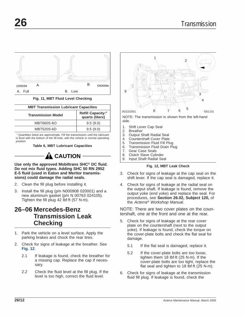
MBT Transmission Lubricant Capacities
Transmission Model Refill Capacity: *quarts (liters)
MBT660S-6O 9.5 (9.0)
MBT520S-6D 9.5 (9.0)* Quantities listed are approximate. Fill the transmission until the lubricant
is level with the bottom of the fill hole, with the vehicle in normal operatingposition.
Table 6, MBT Lubricant Capacities
CAUTIONUse only the approved Mobiltrans SHC ® DC fluid.Do not mix fluid types. Adding SHC 50 RN 2952E-5 fluid (used in Eaton and Meritor transmis-sions) could damage the radial seals.
2. Clean the fill plug before installing it.
3. Install the fill plug (p/n N000908 020001) and anew aluminum gasket (p/n N 00763 024105).Tighten the fill plug 42 lbf·ft (57 N·m).
26–06 Mercedes-BenzTransmission LeakChecking
1. Park the vehicle on a level surface. Apply theparking brakes and chock the rear tires.
2. Check for signs of leakage at the breather. SeeFig. 12 .
2.1 If leakage is found, check the breather fora missing cap. Replace the cap if neces-sary.
2.2 Check the fluid level at the fill plug. If thelevel is too high, correct the fluid level.
3. Check for signs of leakage at the cap seal on theshift lever. If the cap seal is damaged, replace it.
4. Check for signs of leakage at the radial seal onthe output shaft. If leakage is found, remove theoutput yoke (end yoke) and replace the seal. Forprocedures, see Section 26.02, Subject 120, ofthe Acterra® Workshop Manual.
NOTE: There are two cover plates on the coun-tershaft, one at the front and one at the rear.
5. Check for signs of leakage at the rear coverplate on the countershaft (next to the outputyoke). If leakage is found, check the torque onthe cover-plate bolts and check the flat seal fordamage.
5.1 If the flat seal is damaged, replace it.
5.2 If the cover-plate bolts are too loose,tighten them 18 lbf·ft (25 N·m). If thecover-plate bolts are too tight, replace theflat seal and tighten to 18 lbf·ft (25 N·m).
6. Check for signs of leakage at the transmissionfluid fill plug. If leakage is found, check the
f260006b10/05/94 A B
A. Full B. Low
Fig. 11, MBT Fluid Level Checking
05/22/2001 f261101
12
3
4
5678
9
NOTE: The transmission is shown from the left-handside.
1. Shift Lever Cap Seal2. Breather3. Output Shaft Radial Seal4. Countershaft Cover Plate5. Transmission Fluid Fill Plug6. Transmission Fluid Drain Plug7. Gear Case Seals8. Clutch Slave Cylinder9. Input Shaft Radial Seal
Fig. 12, MBT Leak Check
Transmission26
Acterra Maintenance Manual, March 200526/12

torque on the plug and check the aluminum gas-ket for damage.
6.1 If the gasket is damaged, replace it.
6.2 If the fill plug is too loose, tighten it 42lbf·ft (57 N·m). If the fill plug is too tight,loosen it and tighten to 42 lbf·ft (57 N·m).
7. Check for signs of leakage at the transmissionfluid drain plug. If leakage is found, check thetorque on the plug and check the aluminum gas-ket for damage.
7.1 If the gasket is damaged, replace it.
7.2 If the drain plug is too loose, tighten it 42lbf·ft (57 N·m). If the plug is too tight,loosen it and tighten to 42 lbf·ft (57 N·m).
8. Check for fluid dripping at the gear case seals. Ifsubstantial leakage is found at either location,replace the transmission.
NOTE: Weeping or sweating seals are notcause for transmission replacement.
WARNINGClutch hydraulic fluid (DOT 3 brake fluid) is haz-ardous. It may be a skin irritant and can causeblindness if it gets in your eyes. Always wearsafety glasses when handling clutch hydraulicfluid or bleeding hydraulic lines. If you get clutchhydraulic fluid on your skin, wash it off as soonas possible.
9. Check for signs of leakage at the clutch slavecylinder.
CAUTIONDo not spill clutch hydraulic fluid (DOT 3 brakefluid) on the cab paint. Clean it off immediately ifany is spilled. DOT 3 brake fluid can damagepaint.
9.1 If leakage is found on the slave cylinderbody, check the fittings and hose for dam-age.
9.2 If leakage is found on the piston seals,replace the slave cylinder and bleed theclutch hydraulic system. For detailed in-structions, see Group 25 .
9.3 If the slave cylinder fittings and/or thehose are damaged, replace them.
9.4 Check the torque on the slave cylindermounting capscrews. Tighten them 15lbf·ft (20 N·m).
9.5 If any leakage of clutch hydraulic fluid isfound, check the fluid level in the reser-voir, and add fluid if needed. For detailedprocedures, see Group 25 .
NOTE: There are two cover plates on the coun-tershaft, one at the front and one at the rear.
10. Check for signs of leakage at the clutch bellhousing. If leakage is found, check the radialseal on the input shaft, the front cover plate onthe countershaft (inside the clutch bell housing),and the rear radial seal on the crankshaft.
10.1 If the radial seal on the input shaft isleaking, replace the radial seal. For pro-cedures, see Section 26.02, Subject120, of the Acterra® Workshop Manual.
10.2 If the cover plate on the countershaft isleaking, replace the cover plate. Applyliquid gasket (Loctite 518) to the newcover plate when installing it.
10.3 If the rear radial seal on the enginecrankshaft is leaking, replace the rear ra-dial seal. For procedures, see the enginemanufacturer’s manual.
11. Remove the chocks from the tires.
Transmission 26
Acterra Maintenance Manual, March 2005 26/13

Title of Maintenance Operation (MOP) MOP Number
Fifth Wheel Inspecting . . . . . . . . . . . . . . . . . . . . . . . . . . . . . . . . . . . . . . . . . . . . . . . . . . . . . . . . . . . . . . 31–02
Fifth Wheel Lubricating. . . . . . . . . . . . . . . . . . . . . . . . . . . . . . . . . . . . . . . . . . . . . . . . . . . . . . . . . . . . . . 31–03
Frame Fastener Torque Checking. . . . . . . . . . . . . . . . . . . . . . . . . . . . . . . . . . . . . . . . . . . . . . . . . . . . . . 31–01
Frame and Frame Components 31Index, Alphabetical
Acterra Maintenance Manual, January 2003

31–01 Frame Fastener TorqueChecking
Because of "bedding in" (or seating), the frame fas-teners must be torqued at the recommended inter-vals. These intervals apply to new vehicles, and toframe fasteners that have been removed and in-stalled.
NOTE: For off-highway operations, retorque theframe fasteners the first 1000 miles (1600 km),then periodically, depending on the operatingconditions.
CAUTIONMake sure frame fasteners are properly tightened.Continued vehicle operation with loose fastenerscould result in bracket or frame damage.
Typical frame fastener applications include frontframe brackets, suspension brackets, spring brack-ets, fuel tank, exhaust and engine supports, framecrossmembers and gussets, and fifth wheel mountingbrackets.
See Group 00 of the Acterra® Workshop Manual foradditional information on fasteners and torque val-ues.
Tighten all Freightliner AirLiner suspension fastenersto the torque values in Table 1 . Also, tighten all sus-pension air line fittings and air lines.
Freightliner Airliner SuspensionTorque Values
Description Size Torque:lbf·ft (N·m)
Leveling Valve Adjustment Nut 1/4–20 5 (7)
Leveling Valve Mounting BoltNuts 5/16–18 14 (19)
Air Spring Upper MountingLocknuts
3/4–16 45 (61)
1/2–13 23 (31)
Air Spring Lower MountingLocknuts 1/2–13 55 (75)
Leaf Spring Mounting Eye BoltLocknuts 3/4–16 270 (365)
Shock Absorber Upper BracketMounting Locknuts 5/8–11 125 (170)
Freightliner Airliner SuspensionTorque Values
Description Size Torque:lbf·ft (N·m)
Air Spring Upper MountingBracket 5/8–11 125 (170)
Spring Hanger MountingLocknuts 3/4–10 210 (285)
Lateral Control Rod Nut 5/8–11 185 (136)
Table 1, Freightliner AirLiner Suspension TorqueValues
Tighten Hendrickson suspension fasteners to thetorque values given in Table 2 .
Hendrickson SuspensionTorque Values
Description Size Torque:lbf·ft (N·m)
Top Pad to SpringAligning Setscrew(RT/RTE)
— 100–150 (135–200)
Top Pad Nut (RT/RTE) — 275–400 (375–542)
U-Bolt Locknut (U/UE) 7/8–14 237–302 (321–409)
Spring Pin Locknut 1/2–13 45–63 (61–85)
Torque Rod StraddleMount Nut 5/8–11 190 (260)
Torque Rod StudLocknut 1-1/4–12 175–225 (235–305)
Saddle Cap Stud7/8–14
55–65 (75–90)3/4–16
Saddle Cap Locknut(RT/RTE) 7/8–14 225–275 (305–373)
Saddle Cap Locknut(U/UE) 3/4–16 125–145 (169–197)
Adapter-Type BeamEnd Locknut 3/4–16 210–240 (285–325)
Spring Center Bolt
7/16–20 50–60 (70–80)
1/2–2065–75 (90–100)
1/2–13
Rebound SpacerLocknut 1/2–13 38–45 (51–61)
Spring Alignment Clip — 15 (20)
Frame and Frame Components 31
Acterra Maintenance Manual, January 2003 31/1

Hendrickson SuspensionTorque Values
Description Size Torque:lbf·ft (N·m)
Fore and Aft TorqueRod Mount Nut — 95 (130)
Table 2, Hendrickson Suspension Torque Values
All Hendrickson beam end fasteners must maintaintheir torque values to firmly clamp the rubber bushinginner metal tubes to the beam hanger legs.
WARNINGInsufficient beam end fastener torque could causethe beam to separate from the axle. This willcause loss of vehicle control resulting in propertydamage, serious personal injury or death.
Tighten the nut (see Fig. 1 ) to the torque value inTable 2 . Do not over-torque.
Check the drive-axle-flange fasteners (see Fig. 2 ) fortightness. Tighten the fasteners as follows:
Tighten 1/2-inch drive-axle stud nuts (with or withoutdowels) 75 to 115 lbf·ft (102 to 156 N·m), and tighten5/8-inch drive-axle stud nuts 150 to 230 lbf·ft (203 to312 N·m).
31–02 Fifth Wheel Inspecting
WARNINGAll fifth wheel maintenance, adjustment, and re-building must be done only by a qualified me-chanic. Improper or incomplete procedures couldresult in a possible disengagement of the trailerfrom the tractor, which could result in personalinjury or property damage.
Parts are under spring compression. Wear safetygoggles while servicing the fifth wheel. Failure todo so can result in personal injury, due to partsejecting with force.
FontaineDisconnect the tractor from the trailer. For instruc-tions, see Chapter 10 of the Acterra® Driver’sManual. Thoroughly steam clean the fifth wheel, thenmake the following checks:
f320110a05/27/93
1
2
2
3 4
5
NOTE: Do not use the three-piece adapter without theintermediate tube.
1. Nut2. Adapter3. Intermediate Tube
4. Inner Metal of BeamEnd Bushing
5. Beam Hanger
Fig. 1, Three-Piece Adapter-Type Beam End Connection
06/09/94 f400090b
1
2
NOTE: Spoke wheel shown.
1. Drive-Axle-FlangeStuds and Nuts
2. Drive-Axle Flange
Fig. 2, Drive-Axle Flange
Frame and Frame Components31
Acterra Maintenance Manual, January 200331/2

1. Look for cracks in the fifth wheel assembly,mounting brackets, and mounting parts.
2. Check moving parts for wear or damage.
3. Test the safety lock latch for operation.
4. Check for loose nuts and bolts in the fifth wheeland in the mounting.
5. Check that all springs are securely fastened andnot deformed.
6. Check wedge adjustment.
6.1 Open the kingpin lock and insert a 2-inch(51-mm) diameter shaft vertically.
6.2 Release the lock by tripping the releaselatch at the bottom of the throat.
6.3 Adjust the wedge stop at the end of thewedge to approximately 1/4-inch (6-mm)clearance.
7. If you observe any problems doing the previoussteps, correct them immediately. For instructions,see Group 31 of the Acterra® Workshop Manual.
8. Replace cracked, worn, or damaged parts withnew parts. Replace loose mounting bolts with5/8–11 SAE grade 8 bolts, grade C nuts, andhardened washers. Do not reuse bolts, nuts, andwashers on fifth wheel mountings.
HollandDisconnect the tractor from the trailer. For instruc-tions, see Chapter 10 of the Acterra® Driver’sManual Thoroughly steam clean the fifth wheel, theninspect for:
1. Loose nuts or broken bolts on the fifth wheel as-sembly.
2. Cracks or wear on the mounting bolts.
3. Improper locking action; cracks or wear on thejaw locking mechanism.
4. Gouges or wear on the fifth wheel top plate.
5. Fatigued or cracked welds.
6. Replace cracked, worn, or damaged parts withnew parts. Replace loose mounting bolts with5/8–11 SAE grade 8 bolts, grade C nuts, andhardened washers. Do not reuse bolts, nuts, andwashers on fifth wheel mountings.
7. If you observe any problems doing the previoussteps, correct them immediately. For instructions,see Group 31 of the Acterra® Workshop Manual.
31–03 Fifth Wheel Lubricating
FontaineUse a multipurpose extreme pressure (EP) chassisgrease, and lubricate all moving parts on the fifthwheel. When lubricating the top plate at the greasefittings for the bracket bearing area, tilt the top plateforward and backward to evenly distribute thegrease. Using a pry tool, separate the jaw andwedge and lubricate the serrations using a brush todistribute the grease. On slide-mount applications,lubricate the slide rail and tapered wedges forsmooth operation.
Once the moving parts of the fifth wheel are lubri-cated, apply a liberal coating of grease to the topplate and the trailer kingpin plate.
HollandLubricate all moving parts with a multipurpose chas-sis grease. Lubricate the two grease fittings locatedon either side of the top plate with a multipurposechassis grease.
Once the fifth wheel’s moving parts are lubricated,apply a heavy coat of grease to the top plate by di-rect application. On slide-mount applications, lubri-cate the baseplate rails and the plungers for smoothoperation.
Frame and Frame Components 31
Acterra Maintenance Manual, January 2003 31/3

Title of Maintenance Operation (MOP) MOP Number
Suspension Inspecting . . . . . . . . . . . . . . . . . . . . . . . . . . . . . . . . . . . . . . . . . . . . . . . . . . . . . . . . . . . . . . 32–01
Suspension Lubricating. . . . . . . . . . . . . . . . . . . . . . . . . . . . . . . . . . . . . . . . . . . . . . . . . . . . . . . . . . . . . . 32–02
U-Bolt Torque Checking . . . . . . . . . . . . . . . . . . . . . . . . . . . . . . . . . . . . . . . . . . . . . . . . . . . . . . . . . . . . . 32–03
Suspension 32Index, Alphabetical
Acterra Maintenance Manual, September 2002

32–01 Suspension Inspecting
Sterling Front and Rear SuspensionSpring Assemblies InspectingInspect the front and rear suspension spring assem-blies for pitted, cracked, broken, or abnormally bentleaves and extreme rust. If any of these conditionsexist, replace the spring assembly. See Group 32 ofthe Acterra® Workshop Manual for instructions.
WARNINGDo not replace individual leaves of a damaged leafspring assembly; replace the complete spring as-sembly. Visible damage (cracks or breaks) to oneleaf causes hidden damage to other leaves. Re-placement of only the visibly damaged part(s) isno assurance that the spring is safe. On frontspring assemblies if cracks or breaks exist in thetwo top leaves, a loss of vehicle control could oc-cur. Failure to replace a damaged spring assemblycould cause an accident resulting in propertydamage, serious personal injury or death.
IMPORTANT: On multi-leaf suspensions, closelyinspect each component of the leaf spring as-semblies, including the brackets, U-bolts, andrelated parts.
Sterling Spring Rear SuspensionSpring Brackets and EqualizerBrackets InspectingInspect the forward and rear spring brackets, equal-izer brackets, and the wear pads, for wear, cracks,and other damage. If any of these conditions exist,replace the damaged bracket(s) and wear pad(s).See Group 32 of the Acterra® Workshop Manual forinstructions.
WARNINGFailure to replace the forward spring brackets,equalizer brackets, or rear spring brackets if theyare worn, cracked, or otherwise damaged couldresult in progressive damage to and eventualbreakage of the bracket. This could cause a lossof vehicle control resulting in property damage,serious personal injury or death.
Sterling Spring Tandem-AxleSuspension Crossmember andGussets InpsectingInspect the tandem-axle frame crossmember andgussets for wear, cracks, and other damage. If any ofthese conditions exist, replace the damaged parts.See Group 32 of the Acterra® Workshop Manual forinstructions. Check all fasteners for tightness; seeGroup 00 of this manual for torque values.
CAUTIONFailure to replace the suspension crossmember orgussets if they are cracked, worn, or otherwisedamaged could result in damage to the vehiclechassis.
Sterling Spring Shock AbsorberCheckingMake sure that the shock absorber brackets aretight, and that the shock absorber is not striking orrubbing on the frame or some other part of the chas-sis. See Fig. 1 . Check the rubber mounting bushingsand replace if worn. Inspect the shock absorber foroil leakage.
If the shock absorber is worn or damaged, replace itwith a new one.
Sterling Spring (Tandem) Radius RodBushing Checking1. Without detaching the torque arms, attempt to
move (by hand) each of the radius-rod ends up,down, in, and out. If there is any movement, re-place the torque arm.
2. Inspect the weld seams between the torque armtube and the shorter bushing tubes. If there arecracks, replace the torque arm. Do not weld thetorque arm for any reason.
3. Inspect the rubber bushing ends. See Fig. 2 . Re-place the torque arm for any of the following rea-sons:
• There are gaps between the rubber bush-ing and the pin or the outer steel sleeve.
• Either bushing end contacts a torque armpin mounting bolt.
Suspension 32
Acterra Maintenance Manual, September 2002 32/1

• There are cracks in the bushing.
• Part of the rubber bushing extends beyondthe outside diameter of the outer bushingsleeve.
Sterling Spring (Tandem) EqualizerBushing Checking1. Block the frame up enough to take the weight of
the chassis off of the springs. Attempt to movethe equalizer up and down, by using a pry barbetween the top of the equalizer and the top ofthe equalizer bracket. Apply hand pressure only.See Fig. 3 . If movement at the center of theequalizer exceeds 1/8 inch (3 mm), replace theequalizer bushings.
2. With the vehicle unloaded, attempt to move theequalizer side to side using a pry bar betweenthe equalizer and frame rail. Apply hand pressureonly. See Fig. 4 . If clearance between the equal-izer assembly and any frame component or fas-tener is less than 1/8 inch (3 mm), replace theequalizer bushings.
52-Inch Multi-Leaf Spring ComponentCheckNo lubrication is required on the 52-inch multi-leafspring rear suspension.
Inspect the stabilizer bar, if present, for irregularbushing wear or cracks in the brackets. Check therubber helper spring, if present, for cracks.
f320267a10/05/94
1
2
3
1. Upper Mounting Bracket2. Shock Absorber3. Lower Mounting Bracket
Fig. 1, Front Shock Absorber Installation (vehicles builtbefore September 15, 2002)
f320021a05/27/93
Fig. 2, Torque Arm Bushings
f320022a05/27/93
1
2
3
A
A. Measure the change in gap at this point.1. Equalizer Bracket2. Equalizer
3. Pry Bar
Fig. 3, Side View of the Equalizer
Suspension32
Acterra Maintenance Manual, September 200232/2

60-Inch Taper-Leaf SpringComponent CheckNo lubrication is required on the 60-inch taper-leafspring rear suspension.
Inspect the rear shackle brackets for bushing wear orcracks.
Inspect the stabilizer bar, if present, for irregularbushing wear or cracks in the brackets. Check therubber helper spring, if present, for cracks.
Airliner Component ClearanceCheckingCheck that the air line support brackets are posi-tioned so the air lines do not rub against anything.Reposition any configurations that could contact andresult in friction and wear. There must be at least 1inch (25 mm) clearance around the rubber air springwhen inflated. If the clearance is less than 1 inch (25mm), relocate the obstructing parts.
CAUTIONFailure to relocate obstructing parts could resultin damage to the air spring.
Airliner Component Inspecting andOperation Checking
WARNINGInspect the components and check their operationas described below. Failure to perform these in-spections and checks could result in separation ofworn suspension components and loss of vehiclecontrol, possibly causing personal injury or death,or property damage.
1. Chock the front tires. Raise the rear of the ve-hicle so the tires just clear the ground and thesuspension is fully extended. Place safety standsunder the vehicle frame.
2. Squeeze all air springs to check for completedeflation. If any air springs remain partially orfully inflated, see Group 32 of the Acterra®
Workshop Manual.
3. Inspect each air spring for wear at its connectionto its pedestal. Replace any worn air springs; forinstructions, see Group 32 of the Acterra® Work-shop Manual.
4. Inspect the shock absorbers for oil leaks andworn rubber bushings. Replace the shock ab-sorbers and/or rubber bushings if wear or dam-age is noted. For instructions, see Group 32 ofthe Acterra® Workshop Manual.
5. Remove the safety stands and lower the rear ofthe vehicle to the ground. Run the engine untilair pressure of at least 100 psi (689 kPa) ismaintained throughout the system.
6. Check that all air springs are inflated. If the airsprings do not inflate, see Group 32 of the Ac-terra® Workshop Manual for possible causes andcorrections.
AirLiner Control Rod Checking1. Without disconnecting the control rods, attempt
to move (by hand) each of the control rod endsup, down, in, and out. If there is any movement,examine the control rods for wear or damage.Replace if necessary.
2. Inspect the rubber bushings for cracks or cuts.
3. Check for any shifting of the barpin.
f320023a05/27/93
1 2
3
4
5
A
A. 1/8-inch (3-mm) Clearance1. Frame Fasteners2. Frame Rail3. Pry Bar
4. Equalizer5. Equalizer Bracket
Fig. 4, Top View of the Equalizer
Suspension 32
Acterra Maintenance Manual, September 2002 32/3

4. Check for cracks in the metal components andwelds.
NOTE: The AirLiner suspension is manufacturedat numerous weight ratings up to 46,000pounds. The control rod on the 46,000-pound-rated suspension is larger, and is fastened dif-ferently than on other applications; see Group32 of the Acterra® Workshop Manual for re-moval and installation information.
TufTrac1. Inspect the suspension spring assemblies for
pitted, cracked, broken, or abnormally bentleaves and extreme rust. If any of these condi-tions exist, replace the spring assembly.
WARNINGDo not replace individual leaves of a damaged leafspring assembly; replace the complete spring as-sembly. Visible damage (cracks or breaks) to oneleaf causes hidden damage to other leaves. Re-placement of only the visibly damaged part(s) isno assurance that the spring is safe. On frontspring assemblies if cracks or breaks exist in thetwo top leaves, a loss of vehicle control could oc-cur. Failure to replace a damaged spring assemblycould cause an accident resulting in propertydamage, serious personal injury or death.
IMPORTANT: On multi-leaf suspensions, closelyinspect each component of the leaf spring as-semblies, including the brackets, U-bolts, andrelated parts.
2. Inspect the brackets for cracks in the castings.Inspect the V-rod tower welds for cracking orother signs of damage. Also check for contactbetween the frame rail and the upper axle clampbrackets. If contact exists, check the V-rod bush-ing for wear. Check the V-rod fastener torques.
3. Inspect the rubber center bearing and spring tippads for excessive wear, including de-laminationof the rubber-to-metal shim interface, and distor-tion and degradation of rubber.
4. Inspect the V-rods and lower control rods forwear and looseness.
4.1 Without disconnecting the control rods,use your hand to attempt to move each of
the control rod ends up, down, in, andout. If there is any movement, examinethe control rods for wear or damage. Re-place if necessary.
4.2 Inspect the rubber bushings for cracks orcuts.
4.3 Check for any shifting of the barpin.
4.4 Check for cracks in the metal compo-nents and welds.
5. Check all fasteners for looseness.
6. Inspect the shock absorbers for oil leaks andworn rubber bushings. Replace the shock ab-sorbers and/or rubber bushings if wear or dam-age is noted.
Hendrickson Suspension InspectingInspect the suspension assembly for wear, cracks,and damage to its components. Replace the compo-nent(s) if any wear, cracks, or damage exists. Forinstructions, see Group 32 of the Acterra® WorkshopManual. Check all fasteners for tightness.
Check for distorted or frayed rubber at the beam endbushings. If the bushings are damaged, replacethem.
Check that the ends of the equalizer beam are notlower in the beam hanger.
If the equalizer beam ends appear lower, use a jackto raise each beam end, and check for movement ofthe inner metal of the rubber end bushing (seeFig. 5 ). Movement cannot be corrected by tighteningthe fastener, because parts could be damaged. Ifthere is movement, replace the rubber end bushingsand all connecting parts.
After repairs to the suspension, check the fastenertorque after the vehicle has been in service for 2500miles (4000 km). Tighten the adapter-type beam endconnection nut (see Fig. 6 ), 210 to 240 lbf·ft (285 to325 N·m). Do not over-torque.
WARNINGInsufficient beam end fastener torque could causethe beam to separate from the axle. This willcause loss of vehicle control resulting in propertydamage, serious personal injury or death.
Suspension32
Acterra Maintenance Manual, September 200232/4

Hendrickson Leaf Spring AssemblyInspectingNOTE: See Fig. 7 for this procedure.
1. Inspect the spring hangers for wear of the springpin holes, cams, and the spring hanger legs.
2. If equipped with the "RTE" or "UE" series, thegap between the rear (No. 2) spring hanger andthe top spring leaf should measure at least 3/8inch (9.5 mm) in an unloaded condition.
If the measurement is less than 3/8 inch (9.5mm), install new rear (No. 3) extension hangers.Lubricate the bolt threads with SAE 20 oil.Tighten the 1/2–13 locknuts with hardened wash-ers 85 lbf·ft (115 N·m).
3. Inspect the spring leaves for cracks, gouges,wear, or abnormal bends. The no. 1 main andno. 2 wrapper spring leaves (the top two springleaves) may be individually replaced. If equippedwith the "RTE" or "UE" series suspension, thenos. 1, 2, and 3 spring leaves (the top threespring leaves) may be individually replaced. If aspring leaf is damaged below these numbers in apack, replace the spring assembly. In addition,replace both spring assemblies to ensure evenspring deflection.
Hendrickson Radius Rod BushingChecking1. Without detaching the torque arms, attempt to
move (by hand) each of the radius-rod ends up,down, in, and out. If there is any movement, re-place the torque arm.
f320039a05/27/93
1
2
3
1. Beam Hanger2. Equalizer Beam
3. Jack
Fig. 5, Raising the Beam End
f320110a05/27/93
1
2
2
3 4
5
NOTE: Do not use the three-piece adapter without theintermediate tube.
1. Nut2. Adapter3. Intermediate Tube
4. Inner Metal of BeamEnd Bushing
5. Beam Hanger
Fig. 6, Three-Piece Adapter-Type Beam End Connection
f320112a05/27/93
1
2 3
4
A
A. Minimum gap of 3/8 inch (9.5 mm).1. Forward (no. 1) Spring Hanger2. Spring Eye Pin3. Rear (no. 2) Spring Hanger4. Rear (no. 3) Extension
Fig. 7, Unloaded RTE or UE Spring Suspension
Suspension 32
Acterra Maintenance Manual, September 2002 32/5

2. Inspect the rubber bushing ends. Replace thetorque arm if there are gaps between the rubberbushing and the pin or the outer steel sleeve, ifeither bushing end contacts a torque arm pinmounting bolt, if there are cracks in the bushing,or if part of the rubber bushing extends beyondthe outside diameter of the outer bushing sleeve.
Chalmers Suspension CheckingChock the front wheels to prevent the vehicle frommoving. Place the transmission in neutral, and re-lease the spring or driveline brakes before inspectingthe rear suspension.
Power wash the Chalmers rear suspension, or cleanit with a hard-bristle brush before performing a visualinspection.
1. Inspect the rubber bushings for cracks or otherdamage.
Try to move the torque rod ends using yourhands only, and check for any free-play. If free-play is felt, replace the torque rod end bushing.Do not use a pry bar to check for free-play. Useof a pry bar may lead to premature bushing re-placement. See Group 32 of the Acterra® Work-shop Manual for replacement instructions.
2. If equipped with optional shock absorbers, checkfor worn, broken, or damaged shock bushings,heavy corrosion on the shock absorber body, orfluid leaking from the shock absorber. Replacethe shock absorbers if any of these conditionsare found; see Group 32 of the Acterra® Work-shop Manual.
3. Lift the rear of the vehicle and support the frameon jack stands to unload the suspension compo-nents. The vehicle is lifted high enough when thebeam ends are off of the saddles. All jack standsmust be of sufficient strength and rigidity tosafely support the vehicle. Do not perform anywork on or around a vehicle that is supportedsolely by a lifting device.
Visually inspect the walking beam for cracks, orother damage. If damage is found, see Group32 of the Acterra® Workshop Manual for replace-ment instructions.
Keep the vehicle supported by the jack standsfor the next operation.
4. Manipulate the walking beam so that a microme-ter, vernier, or dial caliper can be used to deter-mine the wear area thickness on the bottomface. See Fig. 8 . Measurements should be takena minimum of 1/2 inch (13 mm) from the beamflange edges to eliminate any edge wear thatmay have occurred. Subtract the wear areathickness (see Fig. 8 , Ref. B), from the non-weararea (see Fig. 8 , Ref. A), to determine theamount of wear.
If the beams show any wear greater than theallowable 0.062-inch (1.5-mm) wear, a Chalmerswear plate must be installed, or the walkingbeam must be replaced. See Group 32 of theActerra® Workshop Manual for repair and re-placement instructions.
5. Rotate the restrictor cans 360 degrees and in-spect the cans for cracks, severe corrosion, anddistortion. If any of these conditions are present,or the restrictor can is missing, replace the re-strictor can. See Group 32 of the Acterra® Work-shop Manual for replacement instructions.
09/27/95 f320432
1
A
B
A. Non-Wear AreaB. Wear Area1. Walking Beam
Fig. 8, Walking Beam End Wear Thickness
Suspension32
Acterra Maintenance Manual, September 200232/6

WARNINGReplace all cracked or missing restrictor cans.Failure to do so could lead to loss of vehicle con-trol, which could result in property damage, seri-ous personal injury or death. Vehicles withcracked or missing restrictor cans may be drivenslowly to the nearest workshop for restrictor canreplacement.
6. Remove the jack stands, then lower the vehicle.Check that the spring, or driveline brake is ap-plied, then remove the wheel chocks.
Reyco 79KB Suspension VisualInspectionThe Reyco 79KB suspension requires minimal main-tenance. To provide trouble-free operation in over-the-road applications, do the following inspection.
1. Park the vehicle on level ground. Apply the park-ing brakes, and chock the tires.
2. Check that the torque rod clamps are directedaway from the spring to prevent possible interfer-ence during operation. See Fig. 9 .
3. Check the fit of springs to hangers to ensuregood ride characteristics.
4. Check for elongated holes in the suspensioncomponents. See Group 32 of the Acterra®
Workshop Manual for proper repair procedures.
5. Check bushing condition. Replace any bushingthat is worn, cracked, dry-rotted, or otherwisedamaged. See Group 32 of the Acterra® Work-shop Manual for removal and installation instruc-tions.
6. Check tire condition. If abnormal tire wear isfound, check and replace all worn or damagedcomponents, and check suspension alignment.See Group 32 of the Acterra® Workshop Manualfor component removal and installation proce-dures, and for suspension alignment instructions.
Reyco 79KB Fastener Torque CheckCheck the U-bolt nuts, hanger mounting bolts, torquerod clamp nuts, and the spring retainer bolts forproper fastener torque.
1. Park the vehicle on level ground. Apply the park-ing brakes, and chock the tires.
2. Use a click-type torque wrench to check thatU-bolt nuts are tightened 400 to 450 lbf·ft (540 to610 N·m).
01/04/96 f320488
12
1
1. Torque Rod Clamp 2. Torque Rod
Fig. 9, Reyco 79KB Torque Rod Clamp Position
Suspension 32
Acterra Maintenance Manual, September 2002 32/7
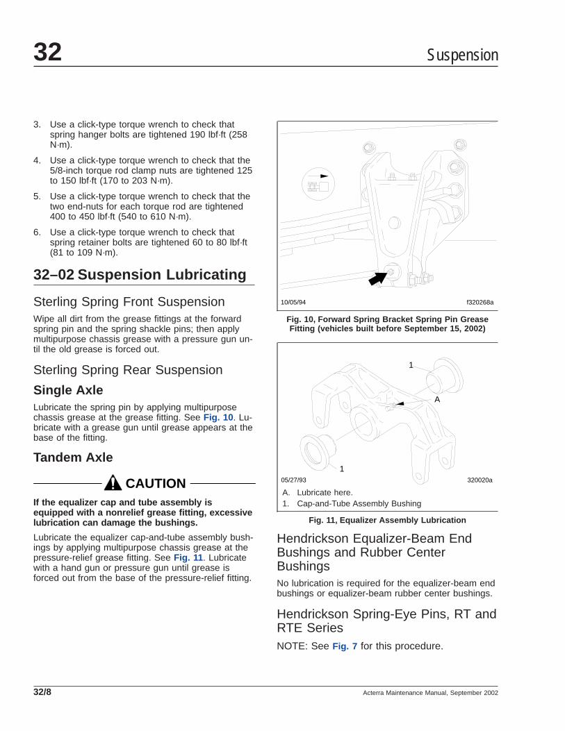
3. Use a click-type torque wrench to check thatspring hanger bolts are tightened 190 lbf·ft (258N·m).
4. Use a click-type torque wrench to check that the5/8-inch torque rod clamp nuts are tightened 125to 150 lbf·ft (170 to 203 N·m).
5. Use a click-type torque wrench to check that thetwo end-nuts for each torque rod are tightened400 to 450 lbf·ft (540 to 610 N·m).
6. Use a click-type torque wrench to check thatspring retainer bolts are tightened 60 to 80 lbf·ft(81 to 109 N·m).
32–02 Suspension Lubricating
Sterling Spring Front SuspensionWipe all dirt from the grease fittings at the forwardspring pin and the spring shackle pins; then applymultipurpose chassis grease with a pressure gun un-til the old grease is forced out.
Sterling Spring Rear Suspension
Single AxleLubricate the spring pin by applying multipurposechassis grease at the grease fitting. See Fig. 10 . Lu-bricate with a grease gun until grease appears at thebase of the fitting.
Tandem Axle
CAUTIONIf the equalizer cap and tube assembly isequipped with a nonrelief grease fitting, excessivelubrication can damage the bushings.
Lubricate the equalizer cap-and-tube assembly bush-ings by applying multipurpose chassis grease at thepressure-relief grease fitting. See Fig. 11 . Lubricatewith a hand gun or pressure gun until grease isforced out from the base of the pressure-relief fitting.
Hendrickson Equalizer-Beam EndBushings and Rubber CenterBushingsNo lubrication is required for the equalizer-beam endbushings or equalizer-beam rubber center bushings.
Hendrickson Spring-Eye Pins, RT andRTE SeriesNOTE: See Fig. 7 for this procedure.
f320268a10/05/94
Fig. 10, Forward Spring Bracket Spring Pin GreaseFitting (vehicles built before September 15, 2002)
320020a05/27/93
1
1
A
A. Lubricate here.1. Cap-and-Tube Assembly Bushing
Fig. 11, Equalizer Assembly Lubrication
Suspension32
Acterra Maintenance Manual, September 200232/8

Apply multipurpose chassis grease at the spring eyepin grease fitting (located on the inboard side of thespring eye pin) until clean grease appears at bothends of the spring eye pin.
TufTracThe TufTrac suspension is maintenance-free and de-signed so that lubrication is not required. There areno provisions for lubrication and attempting to lubri-cate the suspension could shorten component life.
32–03 U-Bolt Torque CheckingCheck the U-bolt torque of both the front and rearaxles (where applicable).
CAUTIONFailure to retorque the U-bolt nuts could result inspring breakage and abnormal tire wear.
1. Park the vehicle on a flat surface and apply theparking brakes. Chock the tires to prevent thevehicle from moving.
2. Check the U-bolt torque in a diagonal pattern.Set a click-type torque wrench to the highesttorque value for the fastener being checked. SeeTable 1 for U-bolt torque specifications. Turn thewrench in a clockwise motion (looking up) untilthe torque wrench clicks.
3. Remove the chocks.
U-Bolt Torque Values
Description Size Torque:lbf·ft (N·m)
Spring Assembly U-Bolt High Nuts*
5/8–18
Stage 1: Hand TightenStage 2: 60 (81)Stage 3: 200 (271)Stage 4: 180 to 230 (245 to 313)
3/4–16
Stage 1: Hand TightenStage 2: 60 (81)Stage 3: 200 (271)Stage 4: 270 to 330 (367 to 449)
7/8–14
Stage 1: Hand TightenStage 2: 60 (81)Stage 3: 200 (271)Stage 4: 420 to 500 (571 to 680)
1–14
Stage 1: Hand tightenStage 2: 60 (81)Stage 3: 200 (271)Stage 4: 520 to 600 (707 to 816)
* Tighten in a diagonal pattern as shown in Fig. 12 .
Table 1, U-Bolt Torque Values
Suspension 32
Acterra Maintenance Manual, September 2002 32/9

01/05/99 f320783
1
2 3
4
Fig. 12, Tightening Pattern for U-Bolt High Nuts
Suspension32
Acterra Maintenance Manual, September 200232/10

Title of Maintenance Operation (MOP) MOP Number
All-Axle Alignment Checking . . . . . . . . . . . . . . . . . . . . . . . . . . . . . . . . . . . . . . . . . . . . . . . . . . . . . . . . . . 33–04
All-Wheel-Drive Front Axle Oil Changing . . . . . . . . . . . . . . . . . . . . . . . . . . . . . . . . . . . . . . . . . . . . . . . . . 33–06
All-Wheel-Drive Front Axle Oil Level Checking. . . . . . . . . . . . . . . . . . . . . . . . . . . . . . . . . . . . . . . . . . . . . 33–05
Draw Key Nut Inspecting. . . . . . . . . . . . . . . . . . . . . . . . . . . . . . . . . . . . . . . . . . . . . . . . . . . . . . . . . . . . . 33-07
Knuckle Pin Lubricating . . . . . . . . . . . . . . . . . . . . . . . . . . . . . . . . . . . . . . . . . . . . . . . . . . . . . . . . . . . . . 33–01
Tie Rod End Inspecting . . . . . . . . . . . . . . . . . . . . . . . . . . . . . . . . . . . . . . . . . . . . . . . . . . . . . . . . . . . . . 33–02
Tie Rod End Lubricating. . . . . . . . . . . . . . . . . . . . . . . . . . . . . . . . . . . . . . . . . . . . . . . . . . . . . . . . . . . . . 33–03
Front Axle 33Index, Alphabetical
Acterra Maintenance Manual, September 2002

33–01 Knuckle Pin Lubricating
Standard Meritor AxlesHold a pressure gun on each fitting until fresh greaseappears. See Fig. 1 . This will ensure that all the oldcontaminated grease has been forced out. It is notnecessary to exceed 4000 psi (27 560 kPa). Thebest distribution of new lubricant and the best purg-ing of old lubricant occurs when about 4000 psi (27560 kPa) pressure is applied at the grease gunnozzle. Using a 40 to 1 booster, the air should belimited to 100 psi (689 kPa); using a 50 to 1 booster,the air should be limited to 80 psi (551 kPa). Higheror lower pressures are not recommended.
When lubricating knuckle pin bushings for InitialMaintenance, raise the front axle until the front tiresare off the ground. Wipe the lube fittings clean, andslowly feed multipurpose chassis grease (NLGI grade1 or 2) into each bushing area while turning thewheels from extreme right to left and back again(lock to lock). This will eliminate small air pocketsand improve grease distribution.
Lower the tires to the ground, and regrease both topand bottom bushings until new grease is seen at theseal on the bushing opposite the fittings. The greaseseal will accept the grease pressure without damag-ing the seal, and is designed to have grease pumpedout through it during lubrication. Even if grease leaks
out around the top or bottom plate gasket, continuepumping until new grease is seen at the seal on thebushing opposite the grease fitting.
When lubricating knuckle pin bushings at M1 throughM5, do not raise the front axle. Wipe the lube fittingsclean, and apply multipurpose chassis grease untilnew grease is seen at the grease seal on the bush-ing opposite the fittings. The grease seal will acceptthe grease pressure without damaging the seal, andis designed to have grease pumped out through itduring lubrication. Even if grease leaks out aroundthe top or bottom plate gasket, continue pumpinguntil new grease is seen at the seal on the bushingopposite the grease fitting.
Sealed and Easy Steer™ AxleKingpinsNOTE: This procedure applies to the followingaxles:
• MFS-8-153B
• MFS-10-143A
• MFS-12-143A
• MFS-13-143A
• MFS-14-143A
• MFS-16-143A
• MFS-18-133A
• MFS-20-133A
• 975 Series Easy Steer sealed front axles
Refer to the identification tag on the front of theaxle beam.
On sealed and Easy Steer™ front axle, the greasefittings are on the top and bottom kingpin caps of theknuckle.
1. Shut off the engine, apply the brakes, and chockthe rear tires.
2. Make sure the tires touch the ground. Donot raise the vehicle.
3. Clean off all grease fittings prior to lubrication.
IMPORTANT: Meritor recognizes that industrytrends are moving toward increased selectionand usage of synthetic grease in vehicle mainte-nance. However, some seals are known to ex-pand when in contact with synthetic grease.
f320032a
1
1
A
10/20/93
A. Pump lubricant into each grease fitting until freshgrease comes out here.
1. Grease Fitting
Fig. 1, Meritor Front Axle
Front Axle 33
Acterra Maintenance Manual, September 2002 33/1

Consult your local Meritor representative forsynthetic grease application references beforeusing any synthetic grease when performingaxle service and maintenance.
4. Using a multipurpose grease, NLGI grade 1 or 2,lubricate the kingpins through the grease fittingson the top and bottom of the knuckle. SeeFig. 2 .
5. Apply lubricant until new lubricant comes fromthe thrust bearing seal and the upper shim pack.
6. Remove the chocks from the tires.
Easy Steer Plus™–Axles WithUnitized Wheel Ends, King PinsNOTE: This procedure applies to Easy SteerPlus™ MFS 10-12-143D sealed front axles. Re-fer to the identification tag on the front of theaxle beam.
On Easy Steer Plus front axles, the grease fittingsare on the top and bottom kingpin caps of theknuckle.
1. Shut off the engine, apply the brakes, and chockthe rear tires.
2. Make sure the tires touch the ground. Donot raise the vehicle.
3. Clean off all grease fittings prior to lubrication.
IMPORTANT: Meritor recognizes that industrytrends are moving toward increased selectionand usage of synthetic grease in vehicle mainte-nance. However, some seals are known to ex-pand when in contact with synthetic grease.Consult your local Meritor representative forsynthetic grease application references beforeusing any synthetic grease when performingaxle service and maintenance.
4. Using a multipurpose grease, NLGI grade 1 or 2,lubricate the kingpins through the grease fittingson the top and bottom of the knuckle. SeeFig. 3 .
5. Force lubricant into the upper and lower kingpingrease fitting caps until new lubricant flows frombetween the upper axle beam end and theknuckle and between the lower axle beam endand the knuckle. See Fig. 3 .
6. Remove the chocks from the tires.
33–02 Tie Rod End InspectingIMPORTANT: If the tie rod end boot is torn ormissing, replace the entire tie rod end. Do notreplace the boot only.
10/10/2001 f330185
1
A
A. Apply lubricant until new lubricant comes from theseareas.
1. Grease Fitting
Fig. 2, Sealed, Easy Steer Kingpin Lubrication10/11/2001 f330184
1A
1
A. Apply lubricant until new lubricant comes from theseareas.
1. Grease Fitting
Fig. 3, Sealed, Easy Steer Plus Kingpin Lubrication
Front Axle33
Acterra Maintenance Manual, September 200233/2

1. Shut off the engine, apply the brakes, and chockthe rear tires.
2. Check the tie rod boot for cracks, tears, or otherdamage. If the tie rod boot is damaged, replacethe entire tie rod end.
3. Grasp by hand (or use a pipe wrench with jawprotectors to avoid gouging the cross tube) andslightly rotate the cross tube toward the front ofthe vehicle and then slightly toward the rear.Then center the cross tube between the stop po-sitions. If the cross tube does not rotate in eitherdirection, replace both tie rod ends.
4. Position yourself directly below the ball studsocket. Using both hands, grab the end as closeto the socket as possible, no more than 6 inches(15.2 cm) from the end. Firmly apply about 100pounds of hand pressure in an up and down mo-tion several times. When moving the assembly,check for any movement at both tie rod ends.See Fig. 4 .
If any movement is detected at one tie rod end,replace both tie rod ends. Always replace tie rodends in pairs, even if only one tie rod end isdamaged.
CAUTIONDo not attempt to straighten a bent cross tube.Doing so could result in damage to the axle. Besure to replace the cross tube with an originalequipment cross tube with the same length, diam-eter, and thread size as the existing cross tube.
5. Check the cross tube for cracks or other dam-age. If the cross tube is bent or damaged, re-place the cross tube.
6. Check the clamps for damage. If a clamp isdamaged, replace the clamp. Replace the entirecross tube assembly if either clamp is welded tothe cross tube.
7. Check for proper installation of the tie rod endclamp to the cross tube. Make sure that the tierod ends are threaded in the cross tube past theclamps and the slots at the cross tube ends. SeeFig. 5 .
8. Check the zerk fittings for damage. If a zerk fit-ting is damaged, replace it.
Some tie rod ends have no zerk fittings becausethey are not to be greased. Do not install a zerkfitting on this type of tie rod end.
9. Check that the cotter pin is in place. If it is not,tighten the tie rod end nut to one of the followingspecs depending on the size of the stud.
• 7/8–14, 160 to 300 lbf·ft (217 to 406 N·m)
• 1–14, 250 to 450 lbf·ft (339 to 610 N·m)
10/10/2001 f330195
Fig. 4, Check Movement of Tie Rod End
f320033a
1
10/20/93
OK
OK
NOTE: Pinch bolt not shown to provide clarity.
1. Cross-Tube Split
Fig. 5, Tie-Rod End Adjustment
Front Axle 33
Acterra Maintenance Manual, September 2002 33/3

• 1-1/8–12, 350 to 650 lbf·ft (475 to 881N·m)
• 1-1/4–12, 500 to 675 lbf·ft (678 to 915N·m)
10. Check the steering arm bolts for a minimumtorque of 300 lbf·ft (406 N·m). If the steering armbolt torque has fallen below this specification,remove the bolt, clean all the threads, and applynew Loctite® 680. Tighten the bolt 300 to 450lbf·ft (406 to 610 N·m).
11. Remove the chocks from the tires.
33–03 Tie Rod End LubricatingThis procedure applies to all tie rod ends on Meritornondrive steering axles.
1. Park the vehicle with the wheels in the straight-ahead position. Turn off the engine, apply thebrakes and chock the rear tires.
2. Wipe the zerk fitting and the seal or boot clean.
NOTE: Synthetic lubricants are not approved fortie rod end lubrication.
3. Using a grease gun, apply a multipurposegrease, NLGI grade 1 or 2, to the zerk fitting untilall the old grease is purged from the boot. Dis-colored old grease should come out of the purgeholes near the boot crimp or bellows area.
Apply grease until all the old grease is purgedfrom the boot.
NOTE: If using an air pressure grease gun, donot exceed 150 psi (1035 kPa).
4. If the tie rod end is designed for lube service andit does not accept grease, perform the followingsubsteps.
4.1 Remove the zerk fitting.
4.2 Inspect the threaded zerk fitting hole inthe tie rod end and remove any obstruc-tions.
4.3 Install a new zerk fitting.
4.4 Apply lubrication to the new zerk fitting.
5. Remove the chocks from the tires.
33–04 All-Axle AlignmentChecking
Drive Axle Alignment CheckingCheck the axle alignment, parallelism, and thrustangle measurements for the rear drive axles. Use theapplicable procedure and specifications in Group 35of the Acterra® Workshop Manual.
Toe-In Checking, Front AxleSee Group 33 of the Acterra® Workshop Manual forwheel alignment procedures.
33–05 All-Wheel-Drive FrontAxle Oil Level Checking
1. On all front-wheel-drive vehicles, check the oillevel in the differential. See Fig. 6 .
1.1 Remove the oil level check-and-fill plug,and make sure the oil level is even withthe bottom of the bore.
1.2 If needed, add oil until the differential isfilled to the bottom of the bore.
1.3 Install the oil level check-and-fill plug, andtighten it firmly.
04/15/96 f350149
1
2
3
1. Vent Valve2. Oil Level Check-and-Fill Plug3. Oil Drain Plug
Fig. 6, All-Wheel-Drive Front Axle Differential
Front Axle33
Acterra Maintenance Manual, September 200233/4

2. On front-wheel-drive vehicles equipped with MT-14, MT-17, and MT-22 axles, check the oil levelin the hubs.
2.1 The oil drain bore must be at the bottomin order to check the oil level. See Fig. 7 .
2.2 Remove the plug from the oil level check-ing bore, and make sure the oil is levelwith the bottom edge of the bore.
2.3 If needed, add oil until each axle hub isfilled to the bottom of the bore.
2.4 Install the plug in each oil level checkingbore, and tighten it firmly.
33–06 All-Wheel-Drive FrontAxle Oil Changing
1. Drive the vehicle until the axle oil is warmed,then park it, and chock the rear tires.
2. Jack up the front axle until the wheels are off theground, then secure the axle on jack stands.
3. On vehicles equipped with an MT-8, MT-10, orMT-11 front axle, drain the oil from the differen-tial.
On vehicles equipped with an MT-14, MT-17, orMT-22 front axle, drain the oil from the differentialand the hubs.
3.1 Remove the oil-drain plug from the differ-ential, and allow the oil to drain. SeeFig. 6 .
3.2 If applicable, rotate each wheel until theoil drain bore is at the bottom, then re-move the drain bore plugs and allow theoil to drain into a suitable container. SeeFig. 7 . If needed use a bent piece ofsheet metal to direct the draining oil so itdoesn’t splash on the tires.
4. Fill the differential and hubs (if applicable) withnew oil.
4.1 Install the drain bore plugs in each huband the differential, then tighten the plugsfirmly.
4.2 Remove the plug from the oil level checkbore in each hub and from the fill-and-check bore in the differential.
4.3 Fill the hubs and differential until the oillevel within each is even with the bottomof the fill-and-check bore.
4.4 Install the check bore plug in each huband install the fill-and-check plug in thedifferential. Tighten all the plugs firmly.
5. Lift the front axle off the jack stands, remove thestands and lower the vehicle to the ground. Thenremove the chocks from the rear tires.
33-07 Draw Key Nut Inspecting
Axles With Unitized Wheel EndsCheck the torque of the nut that holds the draw keyon the side of the knuckle. The torque should be 30to 45 lbf·ft (41 to 61 N·m). See Fig. 8 .
04/10/96
A
M H
f350148
1
2
A. Correct Oil Level1. Oil Level Checking
Bore2. Oil Drain Bore
Fig. 7, All-Wheel-Drive Front Axle Hub, MT-17 Axles
Front Axle 33
Acterra Maintenance Manual, September 2002 33/5

10/11/2001 f330186
Fig. 8, Draw Key Nut
Front Axle33
Acterra Maintenance Manual, September 200233/6

Title of Maintenance Operation (MOP) MOP Number
Axle Breather Checking . . . . . . . . . . . . . . . . . . . . . . . . . . . . . . . . . . . . . . . . . . . . . . . . . . . . . . . . . . . . . 35–02
Axle Lubricant Changing and Magnetic Plug Cleaning . . . . . . . . . . . . . . . . . . . . . . . . . . . . . . . . . . . . . . . 35–03
Axle Lubricant Level Checking . . . . . . . . . . . . . . . . . . . . . . . . . . . . . . . . . . . . . . . . . . . . . . . . . . . . . . . . 35–01
Two-Speed-Axle Shift Unit Oil Changing . . . . . . . . . . . . . . . . . . . . . . . . . . . . . . . . . . . . . . . . . . . . . . . . . 35–05
Two-Speed-Axle Shift Unit Oil Level Checking. . . . . . . . . . . . . . . . . . . . . . . . . . . . . . . . . . . . . . . . . . . . . 35–04
Rear Axle 35Index, Alphabetical
Acterra Maintenance Manual, March 2000

35–01 Axle Lubricant LevelChecking
CAUTIONFailure to keep the rear axle filled to the properlevel with the recommended lubricant can result inrear axle damage.
1. Clean the oil fill hole plug, located in the carrieror the side of the axle housing, and the area sur-rounding it (see Fig. 1 ). Remove the plug.
NOTE: Some Meritor axles have a small tappedand plugged hole located near and below thehousing oil fill hole. This smaller hole is for thelubricant temperature sensor only, and must notbe used as a fill or level hole.
2. With the vehicle on level ground, lubricant mustbe level with the bottom of the oil fill hole.
If low, add lubricant. See Table 1 for approvedaxle lubricants and see Table 2 or Table 3 foraxle capacities.
Meritor Drive Axle Recommended Lubricant
RecommendedLubricant Type Ambient Temperature Lubricant SAE
Viscosity GradeMeritor
Specification
Hypoid Gear OilAPI Service
Classification GL–5
+10°F (–12.2°C) and up* 85W–140 0–76–A
–15°F (–26.1°C) and up* 80W–140 0–76–B
–15°F (–26.1°C) and up* 80W–90 0–76–D
–40°F (–40°C) and up* 75W–90 0–76–E
–40°F (–40°C) to +35°F (+2°C) 75W 0–76–J
–40°F (–40°C) and up* 75W–140 0–76–L
Synthetic Gear Oil–40°F (–40°C) and up* 75W–90 0–76–N
–40°F (–40°C) and up* 75W–140 0–76–M* There is no upper limit on these ambient temperatures, but axle sump temperature must never exceed 250°F (121°C).
Table 1, Meritor Drive Axle Recommended Lubricant
Meritor Drive Axle Lubricant Capacities, Single Axles
Axle Type Axle Model Capacity: *pints (liters) Axle Type Axle Model Capacity: *
pints (liters)
Single†
RS–13–120 16 (7.6)
Single †
RS–19–220 31 (14.7)
RS–15–120 16 (7.6) RS–21–145 32 (15.1)
RS–15–210 16 (7.6) RS–21–160 39.5 (18.7)
RS–17–140 31 (14.7) RS–21–230 39 (18.5)
RS–17–145 33.6 (15.9) RS–23–160 42 (19.9)
RS–17–220 31 (14.7)RS–23–240
45 (21.3)
RS–19–145 34.4 (16.3)* Quantities listed are approximate and include 1 pint (0.5 liter) for each wheel end and with the drive pinion at 3 degrees.† Single drive axles equipped with traction equalizers may require a "friction modifier" to correct a slip-stick condition, as described in the vehicle driver’s
manual. Meritor’s experience shows that the following additives perform adequately: Add Elco No. 2 Friction Modifier (1 ounce [30 ml] of additive for each 1 pint[0.5 liter] of lube capacity) or Lubrizol No. 797 or 762 (1 ounce [30 mL] of additive for each 1 pint [0.5 liter] of lube capacity).
Table 2, Meritor Drive Axle Lubricant Capacities, Single Axles
Rear Axle 35
Acterra Maintenance Manual, March 2000 35/1

Meritor Drive Axle LubricantCapacities, Tandem Axles
Axle Model Capacity: * pints (liters)
RT–34–144 Forward 29.8 (14.1)Rear 34 (16.1)
RT–40–145 Forward 30.4 (14.4)Rear 34.4 (16.3)
* Quantities listed are approximate and include 1 pint (0.5 liter) for eachwheel end and with the drive pinion at 3 degrees.
Table 3, Meritor Drive Axle Lubricant Capacities,Tandem Axles
3. Install the fill hole plug, and tighten it 35 lbf·ft (47N·m).
35–02 Axle Breather CheckingThe axle housing breather (see Fig. 1 ) must remainclean. Whenever the axle lubricant level is checked,check that the axle breather is open. Check moreoften under poor operating conditions. If the breatheris plugged, clean or replace it as needed.
35–03 Axle Lubricant Changingand Magnetic PlugCleaning
A regular schedule for changing the axle lubricant ina particular vehicle and operation can be accuratelydetermined by analyzing oil samples taken from theaxle at specified intervals or mileages. Lubricant sup-pliers frequently make their laboratory facilities avail-able for determining the useful life of their productunder actual service conditions. The final schedulethat is recommended may, for economic reasons, becorrelated with lubricant changes that are governedby climatic conditions and magnetic plug mainte-nance. Change lubricant type and viscosity as cli-matic temperatures demand, regardless of vehiclemileage or established change schedule.
The normal operating temperature of compoundedlubricants during the summer season is about 160°to 220°F (71° to 104°C). The chemicals and addi-tives that give these lubricants increased load-carrying capacity, oxidize faster at temperaturesabove 220°F (104°C), contributing to more rapid lu-bricant deterioration. For this reason, lubricants ofthis type, that operate continuously at high tempera-tures, must be changed more frequently.
CAUTIONFailure to change the axle lubricant at more fre-quent intervals, when adverse operating condi-tions require, could result in axle damage.
Axle Draining and Flushing1. Remove the plug at the bottom of the housing
and drain the lubricant while the unit is warm.Allow enough time for all the old lubricant todrain completely.
2. Flush the unit with clean flushing oil, then drain itcompletely.
IMPORTANT: Do not flush axles with solvent,such as kerosene.
3. Clean the drain plugs. For magnetic drain plugs,a piece of key stock or any other convenientsteel slug may be used to short the two magneticpoles and divert the magnetic field.
06/07/94 f350062a
1
2 3
1. Axle HousingBreathers
2. Carrier Oil Fill Plugs3. Interaxle Differential
Fig. 1, Fill Hole Plug and Axle Housing BreatherLocations
Rear Axle35
Acterra Maintenance Manual, March 200035/2

NOTE: Meritor recommends using magneticplugs with elements having a minimum pickupcapacity of 2 pounds (1 kg) of low-carbon steel,in plate or bar form. Magnets will rapidly loseeffectiveness as collected material bridges thegap between the two poles. Clean or changethe plugs before this occurs. It may be neces-sary to clean or change the plugs one or moretimes between lubrication change intervals.
4. After cleaning the drain plugs, install and tightenthem 35 lbf·ft (47 N·m).
Axle Filling1. With the vehicle on a level surface, fill the axle
housings to the bottom of the oil fill hole (in thecarrier or housing) with lubricant. See Table 1 forapproved axle lubricants and see Table 2 orTable 3 for axle capacities.
NOTE: Meritor axles have a small tapped andplugged hole located near and below the hous-ing oil fill hole. This smaller hole is for the lubri-cant temperature sensor only, and must not beused as a fill or level hole.
2. Install the fill hole plug, and tighten it 35 lbf·ft (47N·m).
3. After filling the carrier and housing assembly withlubricant, drive the vehicle, unloaded, for 1 or 2miles (2 or 3 kilometers) at speeds not to exceed25 mph (40 km/h), to thoroughly circulate thelubricant throughout the assembly.
35–04 Two-Speed-Axle ShiftUnit Oil Level Checking
CAUTIONFailure to keep lubricant at the specified levelcould cause damage to the axle shift unit.
1. Clean the oil fill hole plug in the shift unit housingcover, and the area surrounding it. See Fig. 2.Remove the fill hole plug.
2. The lubricant level should be maintained at thebottom of the fill hole. If low, add the specifiedlubricant.
CAUTIONBefore adding additional lubricant, make sure ofthe type currently in the shift unit. To preventcomponent damage, do not mix engine oil withautomatic transmission fluid.
IMPORTANT: When the vehicle operating tem-peratures are above 0°F (–18°C), use SAE 10heavy-duty engine oil, API service classificationSD (sulfated ash content must not exceed1.85%). When the vehicle operating tempera-tures are below 0°F (–18°C), use one part ofkerosene to three parts of SAE 10 heavy-dutyengine oil, API service classification SD (sul-fated ash content must not exceed 1.85%). Thiscold-weather mixture can be safely used up to32°F (0°C).
Commercially available automatic transmissionfluid may be used in place of SAE 10 engine oil.Automatic transmission fluid can be used for alltemperatures. Do not mix kerosene with auto-matic transmission fluid.
3. Apply a small amount of Loctite® 242, or equiva-lent sealant, to the threads of the fill hole plug.Install the fill hole plug finger-tight; then, using awrench, tighten the plug 1-1/2 turns more.
f350021a 08/06/93
1
2 3
1. Housing Cover Gasket2. Oil Fill Hole Plug3. Shift Unit Housing Cover
Fig. 2, Two-Speed-Axle Shift Unit
Rear Axle 35
Acterra Maintenance Manual, March 2000 35/3

35–05 Two-Speed-Axle ShiftUnit Oil Changing
1. Remove the shift unit housing cover (see Fig. 2 ),and drain the old lubricant. Discard the housingcover gasket, and the old lubricant.
2. Thoroughly wash the axle shift parts and housingcover, and allow them to air dry.
3. Install the housing cover and a new housingcover gasket. Tighten the housing cover cap-screws 90 to 110 lbf·in (1020 to 1240 N·cm),then remove the oil fill hole plug from the cover.
4. Fill the shift unit housing through the oil fill holeuntil the specified lubricant is level with the bot-tom of the opening.
IMPORTANT: When the vehicle operating tem-peratures are above 0°F (–18°C), use SAE 10heavy-duty engine oil, API service classificationSD (sulfated ash content must not exceed1.85%). When the vehicle operating tempera-tures are below 0°F (–18°C), use one part ofkerosene to three parts of SAE 10 heavy-dutyengine oil, API service classification SD (sul-fated ash content must not exceed 1.85%). Thiscold-weather mixture can be safely used up to32°F (0°C).
Commercially available automatic transmissionfluid may be used in place of SAE 10 engine oil.Automatic transmission fluid can be used for alltemperatures. Do not mix kerosene with auto-matic transmission fluid.
5. Apply a small amount of Loctite 242, or anequivalent sealant, to the threads of the oil fillhole plug. Install the oil fill hole plug finger-tight;then, using a wrench, tighten the plug 1-1/2 turnsmore.
Rear Axle35
Acterra Maintenance Manual, March 200035/4

Title of Maintenance Operation (MOP) MOP Number
Wheel Nut Checking. . . . . . . . . . . . . . . . . . . . . . . . . . . . . . . . . . . . . . . . . . . . . . . . . . . . . . . . . . . . . . . . 40–01
Wheels and Tires 40Index, Alphabetical
Acterra Maintenance Manual, March 2000

40–01 Wheel Nut CheckingIMPORTANT: In addition to the maintenanceinterval in this manual, check the wheel nuttorque the first 50 to 100 miles (80 to 160 km)of operation after a wheel has been removedand installed.
When checking wheel nuts on a dual disc assembly,remove one outer nut at a time, tighten the inner nut,then reinstall the outer nut. Repeat this procedure forall of the inner wheel nuts in the sequence shown inFig. 1 , then tighten all of the outer wheel nuts in thesame sequence.
CAUTIONToo little wheel nut torque can cause wheelshimmy, resulting in wheel damage, stud break-age, and extreme tire tread wear. Too much wheelnut torque can break studs, damage threads, andcrack discs in the stud hole area.
See Table 1 , Table 2 , or Table 3 for wheel nuttorque specifications.
Fastener Torque for 10-Hole Disc WheelWith Inner and Outer Locknuts
Description Nut Size WheelManufacturer
Torque (dry threads):lbf·ft (N·m)
Front Wheel Nut 3/4–16, 1-1/8–16 Accuride 450–500 (610–680)
Rear Wheel Inner Nut 3/4–16 Accuride 450–500 (610–680)
Rear Wheel Outer Nut 1-1/8–16 Accuride 450–500 (610–680)
Wheel Stud Retainer Nut 3/4–16 Accuride 175–200 (235–270)
Table 1, Fastener Torque for 10-Hole Disc Wheel With Inner and Outer Locknuts
Fastener Torque for 8-Hole Disc WheelWith Cone Locknuts
Description Nut Size Torque (lubricated threads):lbf·ft (N·m)
Front and Rear Wheel Nuts M20 280–310 (380–420)
Table 2, Fastener Torque for 8-Hole Disc Wheel With Cone Locknuts
Spoke-Type Wheel Fastener Torque
Description Size WheelManufacturer
Torque (dry threads):lbf·ft (N·m)
Front Wheel Nut, 5- and6-Spoke 3/4–10 Gunite 200–225 (270–305)*
Rear Wheel Nut, 5- and6-Spoke With Channel Spacer 3/4–10 Gunite 200–225 (270–305)
Rear Wheel Nut, 5- and6-Spoke With CorrugatedChannel Spacer
3/4–10 Gunite 240–260 (325–350)
* On front axles with over 12,000 lbs (5448 kg) capacity, tighten the wheel nuts 240 to 265 lbf·ft (325 to 359 N·m).Gunite part number W–854 nut with a phosphate and oil coating must be used.
Table 3, Spoke-Type Wheel Fastener Torque
Wheels and Tires 40
Acterra Maintenance Manual, March 2000 40/1

1
2
3
45
6
7
8
9
101
2
3
45
6
1
2
3 4
5
f40005705/27/93
1 2
3
4
5 6
7
8
A B C D
A. 8-Stud Disc WheelB. 10-Stud Disc Wheel
C. 6-Spoke WheelD. 5-Spoke Wheel
Fig. 1, Wheel Nut and Rim Nut Tightening Sequence
Wheels and Tires40
Acterra Maintenance Manual, March 200040/2

Title of Maintenance Operation (MOP) MOP Number
Driveline Inspecting . . . . . . . . . . . . . . . . . . . . . . . . . . . . . . . . . . . . . . . . . . . . . . . . . . . . . . . . . . . . . . . . 41–01
Driveline Lubricating. . . . . . . . . . . . . . . . . . . . . . . . . . . . . . . . . . . . . . . . . . . . . . . . . . . . . . . . . . . . . . . . 41–02
Driveline 41Index, Alphabetical
Acterra Maintenance Manual, March 2000

41–01 Driveline Inspecting
Inspecting1. Check that the yoke-strap capscrews (see Fig. 1 ,
Ref. 4) are tightened as follows:
• Dana Spicer 1590 and 1610: 50 to 60 lbf·ft(68 to 81 N·m)
• Dana Spicer 1710: 125 to 135 lbf·ft (170 to183 N·m)
CAUTIONDo not overtighten the yoke-strap capscrews, dueto the extreme load occurring at high-speed rota-tion. A loose or broken capscrew at any point inthe driveline weakens the driveline connection,which could eventually result in serious vehicledamage.
2. Check each of the output and input end yokes(see Fig. 1 , Refs. 2 and 11) for cracks andlooseness. Replace cracked yokes. If any endyoke can be moved in or out on its shaft, or canbe rocked on its shaft, disconnect the driveshaftand U-joint from the end yoke. Check the drivecomponent’s shaft seal for leakage or other vis-ible damage that may have been caused by theloose yoke. Replace the seal if needed. Tightenthe end-yoke nut to the value in Table 1 . If theend yoke is still loose after tightening the yokenut, install a new yoke and yoke nut.
NOTE: If the end-yoke locknut was removed forany reason, install a new one.
3. Check the U-joint assemblies for wear by at-tempting to move the driveshaft up and down,and from side to side. If movement of the U-jointtrunnion in the bearings is greater than 0.006inch (0.15 mm), replace the U-joint assembly.
4. Check the midship bearing and bracket for loose-ness and deterioration by attempting to move thedriveshaft up and down, and from side to side. Ifthe bearing is loose on its shaft, or rattles, re-place it. If the bearing bracket is loose on theframe, or the bearing mount is loose on thebracket, tighten the mounting bolt nuts 91 lbf·ft(123 N·m). Replace the midship bearing assem-bly if the rubber cushion is worn or oil-soaked.
End-Yoke Nut Torque Specifications
Description Thread Size Torque:lbf·ft (N·m)
Transmissions
Allison AT-545 1/2–20* 100–120(140–160)
Allison MD Series 2–16 600–800(815–1085)
Single Axle Input Shaft
Meritor RS–13–120,RS–15–120 and –210,RS–17–140 and –20,RS–19–145 and –220,andRS–21–145 and –230
M32 x 1.5 740–920(1000–1250)
Meritor RS–23–160 M45 x 1.5 1000–1230(1355–1670)
Meritor RS–23–240 M39 x 1.5 920–1130(1250–1530)
Tandem Axle Input and Output Shafts
MeritorRD– and RR–17–145,(of RT–34–145), andRD– and RR–20–145(of RT–40–145)
M39 x 1.5 920–1130(1250–1530)
Coupling Shaft (Midship Bearings)
Dana Spicer 1590, 1610,and 1710 1-1/4–18 475–525
(644–712)* The Allison AT-545 transmission output shaft end-yoke is retained by a
1/2-20 x 1-1/2-inch bolt and a 1-1/16-inch washer. Both the bolt and thewasher must be replaced each time they are removed.
Table 1, End-Yoke Nut Torque Specifications
5. Check the slip-joints for spline wear by trying tobend the sleeve-yoke and splined shaft back andforth (see Fig. 2 ). If looseness is greater than0.007 inch (0.18 mm), replace both the sleeve-yoke and the splined shaft.
6. Check the driveshaft tubes for dents, bends,twists, or other damage. If any tube appears tobe damaged, remove the driveshaft and checkthe runout on the tube. If the tube is not straight(and cannot be straightened) within 0.015 inch(0.38 mm) on the slip-joint seal surface of thesplined shaft, 0.020 inch (0.51 mm) on the tube3 inches (76 mm) from the front and rear welds,and 0.025 inch (0.635 mm) at the center of thetube, replace the tube. See Fig. 3 .
Driveline 41
Acterra Maintenance Manual, March 2000 41/1

If the driveshaft tube requires straightening orreplacement, balance the repaired driveshaft be-fore installing it. See Group 41 of the Acterra®
Workshop Manual.
7. Check the driveshaft for missing balanceweights, and for debris build-up. Remove anybuild-up. If any balance weights are missing, re-move the driveshaft and have it balanced; seeGroup 41 of the Acterra® Workshop Manual.
8. For driveshafts with slip-joints, check that theyoke plug is not loose or missing. See Fig. 4 ,Ref. 2. Replace the yoke plug if needed. If theyoke plug is missing, the splined shaft may be
hitting the yoke plug and knocking it out; checkthe driveshaft for proper length.
41–02 Driveline Lubricating
U-Joint Lubricating1. Wipe all old grease and dirt from each U-joint
grease fitting. See Fig. 4 , Ref. 8.
2. Use a hand-type grease gun, or a high-pressuregun with a low-pressure adapter, to lubricate theU-joints.
f410057a10/06/94
1 2
3
56
4
2
4
716
15
14
13
18
17
9
8
3
7
1011
12
NOTE: Not all fasteners are shown.
1. Transmission2. Half-Round End Yoke3. U-Joint Assembly4. Yoke Strap and Capscrew5. Coupling Shaft6. Midship Bearing and Mount7. Bearing Cup
8. Slip-Joint Assembly9. Driveshaft Tube10. Driveshaft Yoke11. Input Shaft Half-Round End
Yoke12. Rear Axle
13. Splined Shaft14. Dust Seal15. Sleeve Yoke16. Full-Round-Yoke Lug17. U-Joint Cross18. Lockplate and Capscrew
Fig. 1, Driveline Assembly With Midship Bearing for Single-Axle Installation
Driveline41
Acterra Maintenance Manual, March 200041/2

NOTE: If a low-pressure adapter is not usedwith the high-pressure gun, the U-joints may notreceive enough lubricant.
3. Using lithium 12-hydroxy stearate grease (NLGIgrade 1 or 2, with EP additives), lubricate untilnew grease can be seen at all four U-joint seals.
IMPORTANT: Fresh lubricant must be seen es-caping from all four bearing cup seals of eachU-joint.
On full-round yokes, if most of the grease beingadded to a U-joint can be seen escaping fromjust one of the U-joint seals, bend the tabs ofthe lockstrap away from the heads of the bear-ing cup capscrews, then check the torque onthe bearing cup capscrews at that seal. Tightenthe bearing cup capscrews as follows:
• 5/16–24 capscrews: 24 lbf·ft (32 N·m)
• 3/8–24 capscrews: 37 lbf·ft (50 N·m)
Bend the lockstrap tabs up, against a flat side ofeach capscrew. If the capscrews were alreadytight, or all of the U-joint seals still do not purge,remove the bearing cup at that seal, and exam-ine the seal for damage. If the seal is damaged,replace the complete U-joint assembly.
If grease does not appear at one of the seals,use a screwdriver to pry the U-joint trunnionaway from the non-purging seal, or tap thedriveshaft or yoke with a plastic or rawhide mal-let (on the side opposite the dry seal), whilecontinuing to apply gun pressure. If grease stilldoes not appear, bend the tabs of the lockstrapaway from the heads of the bearing cup cap-screws, then loosen the bearing cup capscrews
f410012a05/27/93
Attempt to bend the sleeve yoke and splined shaft backand forth.
Fig. 2, Slip-Joint Spline Wear Checking
f410110b06/13/96
A A
B
C CD
A. Measurement: 3" (76 mm)B. Measurement: 0.015" (0.38 mm)C. Measurement: 0.020" (0.51 mm)D. Measurement: 0.025" (0.635 mm)
Fig. 3, Driveshaft Runout Specifications
f410050a 10/20/93
1
1
2 3
3
3 4
5
6
7
8
A
A. After grease appears, cover the pressure-relief holewhile continuing to lubricate.
1. Slip-Joint GreaseFitting (with greasegun attached)
2. Yoke Plug3. Grease4. Half-Round Yoke
5. Yoke Plug Pressure-Relief Hole
6. Slip-Joint Seal7. Full-Round Yoke8. U-Joint Grease Fitting
Fig. 4, Slip-Joint and U-Joint Lubricating
Driveline 41
Acterra Maintenance Manual, March 2000 41/3

(at the bearing with the dry seal) to relieve sealtension. Lubricate the U-joint until the oldgrease is purged, then tighten the capscrews tothe above specifications, and bend the tabs ofthe lockstrap against a flat side of each cap-screw. If the bearing will not take grease, re-place the U-joint assembly; see Group 41 of theActerra® Workshop Manual.
4. Check the old grease. If it appears rusty, gritty, orburned, replace the U-joint assembly. See Group41 of the Acterra® Workshop Manual.
5. Wipe any excess grease from the seals andgrease fittings.
Slip-Joint Spline Lubricating1. Wipe all old grease and dirt from the slip-joint
grease fitting. See Fig. 4 , Ref. 1.
2. Use a hand-type grease gun or a high-pressuregun with a low-pressure adapter, to lubricate theslip-joint. Using lithium 12 hydroxy stearategrease (NLGI grade 1 or 2, with EP additives),lubricate until fresh grease appears at thepressure-relief hole in the yoke plug. Then coverthe relief hole with your finger, while continuingto lubricate until fresh grease appears at the slip-joint seal (see Fig. 4 , Ref. 6). This ensures com-plete lubrication of the splines.
3. Wipe any excess grease from the pressure-reliefhole, slip-joint seal, and grease fitting.
Driveline41
Acterra Maintenance Manual, March 200041/4

Title of Maintenance Operation (MOP) MOP Number
Air Brake Valve Disassembly, Cleaning, and Inspecting, Bendix E–8P, R–12,R–14, SR–1, ST–3, TC–6, and TP–3DC. . . . . . . . . . . . . . . . . . . . . . . . . . . . . . . . . . . . . . . . . . . . . . . . . 42–16
Air Brake Valve Inspecting and Leak Checking, Bendix BP–R1 . . . . . . . . . . . . . . . . . . . . . . . . . . . . . . . . 42–02
Air Brake Valve Leak Checking, Bendix TC–6 . . . . . . . . . . . . . . . . . . . . . . . . . . . . . . . . . . . . . . . . . . . . . 42–14
Air Brake Valve Operation Checking . . . . . . . . . . . . . . . . . . . . . . . . . . . . . . . . . . . . . . . . . . . . . . . . . . . . 42–04
Air Dryer Checking, Bendix AD–9 . . . . . . . . . . . . . . . . . . . . . . . . . . . . . . . . . . . . . . . . . . . . . . . . . . . . . . 42–12
Air Dryer Desiccant Replacing, Bendix AD–9. . . . . . . . . . . . . . . . . . . . . . . . . . . . . . . . . . . . . . . . . . . . . . 42–13
Air Dryer Inspecting, Bendix AD–9 . . . . . . . . . . . . . . . . . . . . . . . . . . . . . . . . . . . . . . . . . . . . . . . . . . . . . 42–01
Air Reservoir Automatic Drain Valve Disassembly, Cleaning, Inspecting, andLubricating, Bendix DV–2. . . . . . . . . . . . . . . . . . . . . . . . . . . . . . . . . . . . . . . . . . . . . . . . . . . . . . . . . . . . 42–15
Automatic Slack Adjuster Checking, Meritor. . . . . . . . . . . . . . . . . . . . . . . . . . . . . . . . . . . . . . . . . . . . . . . 42–09
Automatic Slack Adjuster Inspecting and Adjusting, Gunite. . . . . . . . . . . . . . . . . . . . . . . . . . . . . . . . . . . . 42–21
Automatic Slack Adjuster Inspecting, Meritor . . . . . . . . . . . . . . . . . . . . . . . . . . . . . . . . . . . . . . . . . . . . . . 42–11
Automatic Slack Adjuster Lubricating, Gunite. . . . . . . . . . . . . . . . . . . . . . . . . . . . . . . . . . . . . . . . . . . . . . 42–20
Automatic Slack Adjuster Lubricating, Haldex . . . . . . . . . . . . . . . . . . . . . . . . . . . . . . . . . . . . . . . . . . . . . 42–22
Automatic Slack Adjuster Lubricating, Meritor . . . . . . . . . . . . . . . . . . . . . . . . . . . . . . . . . . . . . . . . . . . . . 42–10
Bosch Rail-Slide Hydraulic Brake Caliper Lubricating. . . . . . . . . . . . . . . . . . . . . . . . . . . . . . . . . . . . . . . . 42–23
Brake Chamber Inspecting (All Models). . . . . . . . . . . . . . . . . . . . . . . . . . . . . . . . . . . . . . . . . . . . . . . . . . 42–07
Brake Lines Checking, Hydraulic Disc Brakes . . . . . . . . . . . . . . . . . . . . . . . . . . . . . . . . . . . . . . . . . . . . . 42–18
Brake Lining Wear Checking, Hydraulic Disc Brakes . . . . . . . . . . . . . . . . . . . . . . . . . . . . . . . . . . . . . . . . 42–17
Camshaft Bracket Bushing Lubricating . . . . . . . . . . . . . . . . . . . . . . . . . . . . . . . . . . . . . . . . . . . . . . . . . . 42–08
Foot Brake Valve Actuator Lubricating, Bendix E–8P . . . . . . . . . . . . . . . . . . . . . . . . . . . . . . . . . . . . . . . . 42–03
Power Booster Checking, Bendix Hydro-Max®. . . . . . . . . . . . . . . . . . . . . . . . . . . . . . . . . . . . . . . . . . . . . 42–19
Quick Release and Flipper Valves Checking, Midland . . . . . . . . . . . . . . . . . . . . . . . . . . . . . . . . . . . . . . . 42–06
Relay Valve Checking, Midland. . . . . . . . . . . . . . . . . . . . . . . . . . . . . . . . . . . . . . . . . . . . . . . . . . . . . . . . 42–05
Brakes 42Index, Alphabetical
Acterra Maintenance Manual, October 2004

42–01 Air Dryer Inspecting,Bendix AD–9
1. Check the reservoirs for moisture. A smallamount (teaspoon or less) is normal. Largeramounts may mean that the desiccant needs tobe replaced. Check the mounting and connectinglines.
2. Tighten the fasteners that attach the air dryer tothe vehicle. Use the following torque values:
• 28 lbf·ft (38 N·m) for SAE grade 5, 3/8–16fasteners
• 135 lbf·ft (183 N·m) for SAE grade 5,5/8–11 fasteners
3. Check all air lines, fittings, and electrical connec-tions for damage, leakage, or looseness.
4. Replace damaged or leaking parts, and tightenloose fittings or electrical connections.
42–02 Air Brake ValveInspecting and LeakChecking, Bendix BP–R1
1. Clean the valve exterior and inspect it for corro-sion and damage.
2. Inspect the air lines connected to the valve forsigns of wear or damage. Replace the lines asneeded.
3. Check the valve for leakage.
3.1 Apply the service brakes and hold themon full line pressure of at least 80 psi(550 kPa).
3.2 Check the air line fittings for leaks; tightenor replace the fittings as needed.
3.3 Coat the exhaust port and body of thevalve with soapy water, and check forleakage. Leakage is excessive if it pro-duces a 1-inch (25-mm) bubble within 5seconds.
If the brake valve does not function asdescribed above, or if leakage is exces-sive, replace it with a new or remanufac-tured unit. Repeat the leakage checksbefore placing the brake valve in service.
42–03 Foot Brake ValveActuator Lubricating,Bendix E–8P
1. Clean any dirt, gravel, and other foreign debrisfrom the plunger boot and brake base bracket.
2. Check the brake plunger boot for cracks, holes,or deterioration. Replace if necessary.
3. Lift up the edge of the brake plunger boot andcheck the plunger for existing lubrication.
3.1 If the plunger is dry, remove it by remov-ing the cotter pin from the clevis pin andpulling the clevis pin out. Remove the pis-ton rod and boot. Lift out the plunger. Lu-bricate the plunger and the tip of the pis-ton rod with barium grease part numberBW 246671, or Penzoil Adhezoplex EP 2.Install the piston rod, boot, clevis pin, andcotter pin.
3.2 If the plunger has grease on it, lift theedge of the brake plunger boot enough toapply 2 to 4 drops of light oil around thebrake plunger. Do not over-oil. Install theplunger boot.
4. Lubricate the clevis pin with light oil.
5. Check for leakage. For instructions, see Group42 of the Acterra® Workshop Manual.
42–04 Air Brake ValveOperation Checking
Check for proper operation of the brake air valves.For instructions, see Group 42 of the Acterra® Work-shop Manual.
42–05 Relay Valve Checking,Midland
1. Park the vehicle on a level surface. Chock thetires.
2. Start the engine and run it long enough to pres-surize the air system to at least 80 psi (550 kPa).Turn off the engine. Repeat as necessary tomaintain 80 psi (550 kPa) pressure during thischeck.
Brakes 42
Acterra Maintenance Manual, October 2004 42/1

3. Clean any road grime from the relay valve andany debris from the valve exhaust port.
4. Listen for air leakage around the fittings or ex-haust port. Tighten the fittings as necessary. Usetwo wrenches to avoid twisting the tubing.
5. If the valve fails this check or is damaged, repairor replace it. For instructions, see the Midlandservice manual.
6. Remove the chocks from the tires.
42–06 Quick Release andFlipper Valves Checking,Midland
1. Park the vehicle on a level surface. Chock thetires.
2. Start the engine and run it long enough to pres-surize the air system to at least 80 psi (550 kPa).Turn off the engine. Repeat as necessary tomaintain 80 psi (550 kPa) pressure during thesechecks.
3. Clean any road grime from the valves and anymaterial from the valves’ exhaust ports.
4. Listen for air leakage around the fittings and ex-haust ports. Tighten the fittings as necessary.Use two wrenches to avoid twisting the tubing.
5. If any valve fails this check or is damaged, repairor replace it. For instructions, see the Midlandservice manual.
6. Remove the chocks from the tires.
42–07 Brake ChamberInspecting (All Models)
WARNINGDo not loosen or remove the parking brake clampring for any purpose at any time. See Fig. 1. Theparking/emergency brake section is not intendedto be serviced. Serious injury or death may resultfrom sudden release of the power spring.
Before doing any repairs or adjustments on aservice/parking brake chamber, read the appli-cable warnings and instructions in the applicable
brake chamber section in Group 42 of the Ac-terra ® Workshop Manual .
WARNINGDo not operate the vehicle with the front brakesbacked off or disconnected. Backing off or discon-necting the front brakes will not improve vehiclehandling and may lead to loss of vehicle controlresulting in property damage or personal injury.
NOTE: Vehicles operating under severe or ad-verse conditions should be checked more fre-quently. If the brake chamber requires disas-sembly, see Group 42 of the Acterra®
Workshop Manual for instructions.
1. With the slack adjuster properly adjusted, checkthe angle formed by the centerline of the pistonrod and slack adjuster. This angle should begreater than 90 degrees in the released positionand approach 90 degrees in the applied position.See Fig. 2 .
At angles less than 90 degrees, brake chamberforce is reduced, which reduces brakingefficiency.
1
A
02/22/2000 f421352
A. Do not remove the factory-sealed clamp ring.1. Model TR-T (TR Series) Brake Chamber
Fig. 1, MGM Brake Chamber
Brakes42
Acterra Maintenance Manual, October 200442/2

2. Check each brake chamber for correct installa-tion.
2.1 Check each mounting stud for the pres-ence of prevailing torque locknuts andhardened flatwashers. Make sure that thehardened flatwashers are installed be-tween the mounting bracket and the lock-nuts. Do not install flatwashers touchingthe service (non-pressure) chamber.
2.2 If the locknuts are loose, tighten them.For correct torque values, see the appli-cable brake chamber section in Group 42of the Acterra® Workshop Manual.
3. Observe the piston rod engagement with the cle-vis. Engagement of at least 7 threads is required;there should be 1-inch (25-mm) clearance fromthe centerline of the clevis pin hole to the end ofthe piston rod. See Fig. 3 . Adjust if needed.
4. Check the tightness of the piston rod nut. SeeTable 1 for torque values. Tighten if needed.
5. See if the chamber piston rod is in line with theslack adjuster. Misalignment can cause the pis-ton rod to rub on the non-pressure chamber andcause a dragging brake. Reposition the brakechamber on the mounting bracket, if necessary.
Piston Rod Nut Torque Values
Description Rod Size:inch
Torque:lbf·ft (N·m)
MGM Tandem Chambers All 25–35 (34–47)
Midland Service Chambers1/2 20–30 (27–41)
5/8 33–90 (45–122)
Table 1, Piston Rod Nut Torque Values
6. Inspect the condition of the hose(s) to the brakechamber. Check carefully for chafing, restrictionssuch as kinking or bending, and make sure thehoses are properly supported. Replace a dam-aged hose with the same size hose. With theservice brakes applied, check for leaks at thehose-to-chamber connections. Any leaks areprobably caused by loose connections or by adamaged hose fitting. Eliminate all leaks.
WARNINGRead and follow all applicable warnings and in-structions in Group 42 of the Acterra ® WorkshopManual for repairs to the service/parking brake
f420009a07/27/94
1
3
2
C
B
A
A. Brakes ReleasedB. Brakes Applied
C. Greater than 90degree angle
1. Brake Chamber2. Piston Rod
3. Slack Adjuster
Fig. 2, Angle Between Piston Rod and Slack Adjuster
f420225a
1
2
3
B
A
08/20/93
4
5
A. Minimum of 1-inch (25-mm) clearance betweencenterline of clevis pin hole and piston rod end.
B. Minimum of 7 threads engagement.1. Piston Rod2. Piston Rod Nut3. Clevis
4. Cotter Pin5. Clevis Pin
Fig. 3, Piston Rod Engagement With the Clevis
Brakes 42
Acterra Maintenance Manual, October 2004 42/3

chambers. These chambers contain a powerspring which, if released, could cause serious in-jury or death.
7. Inspect the exterior surfaces of the chamber fordamage. Make sure the breather holes in thenon-pressure section(s) are open and free of de-bris. Using the instructions in Group 42 of theActerra® Workshop Manual, replace any dam-aged parts.
8. On parking brake chambers equipped with inte-gral release bolts, lubricate the bolt with threadanti-seize compound. Check the tightness of thebolt. For torque values, see the applicable brakechamber section in Group 42 of the Acterra®
Workshop Manual.
CAUTIONIf the external breather tube is missing or incor-rectly installed, road dirt and debris can adverselyaffect the operation of the brake chamber. Onceinside the chamber, dirt and debris cause the in-ternal parts to deteriorate and shorten their lives.
9. On brake chambers equipped with an externalbreather tube, make sure the flexible elbows arein place and the connector tube is inserted intoeach elbow 1/2 inch (13 mm).
10. On all parking brake installations, check for pres-ence of an end cover cap or dust plug and makesure the cap or plug is securely snapped intoplace.
Service Brake Operation andLeakage Checking
WARNINGDo not loosen or remove the parking brake clampring for any purpose at any time. See Fig. 1. Theparking/emergency brake section is not intendedto be serviced. Serious injury or death may resultfrom sudden release of the power spring.
WARNINGBefore doing any repairs or adjustments on aservice/parking brake chamber, read the appli-cable warnings and instructions in the applicable
brake chamber section in Group 42 of the Ac-terra ® Workshop Manual .
1. Apply the service brakes and check that the pis-ton rods move out promptly without binding.
2. Release the service brakes and check that thepiston rods return to the released positionspromptly without binding.
WARNINGRead and follow all applicable warnings and in-structions in Group 42 of the Acterra ® WorkshopManual for repairs to the service/parking brakechambers. These chambers contain a powerspring, which if released, could cause serious in-jury or death.
3. Check the service brake chambers for leakage.
3.1 Apply the service brakes and hold themon full line pressure of at least 80 psi(550 kPa).
CAUTIONDo not overtighten the clamp ring. This can distortthe flange sealing surface, or the clamp ring itself.
3.2 Using soapy water, coat the servicechamber clamp ring. Leakage is exces-sive if it produces a 1-inch (25-mm)bubble within 5 seconds. See Fig. 1 . OnBendix service chambers, tighten theclamp ring enough to stop the leakage,but do not exceed the maximum torquelimits in Table 2 . Do not overtighten.
On other service chamber makes, if leak-age is detected, tighten the clamp ring;but do not exceed the maximum torquelimits in Group 42 of the Acterra® Work-shop Manual.
Clamp Ring Torque Values (Bendix Chambers)
Description Torque:lbf·in (N·cm)
5/16–24 Nut 130–150 (1460–1700)
3/8–16 Nut 140–180 (1580–2040)
Table 2, Clamp Ring Torque Values (BendixChambers)
Brakes42
Acterra Maintenance Manual, October 200442/4

3.3 If leakage persists, use the instructions inGroup 42 of the Acterra® WorkshopManual to replace the service brake dia-phragm.
3.4 Using soapy water, coat the area aroundthe piston-rod bore. On some Bendix ser-vice chambers loosen the boot, if neces-sary. No leakage is permitted. If there isleakage, use the instructions in the appli-cable brake chamber section in Group 42of the Acterra® Workshop Manual andreplace the service brake diaphragm.
NOTE: On weatherproof Bendix chambers, theleakage check can be performed at the cross-drilled mounting stud.
Parking Brake Operation andLeakage Checking
WARNINGDo not loosen or remove the parking brake clampring for any purpose at any time. See Fig. 1. Theparking/emergency brake section is not intendedto be serviced. Serious injury or death may resultfrom sudden release of the power spring.
Before doing any repairs or adjustments on aservice/parking brake chamber, read the appli-cable warnings and instructions in the applicablebrake chamber section in Group 42 of the Ac-terra ® Workshop Manual .
1. Park the vehicle on a level surface. Chock thetires.
2. Build the air pressure in the system to at least100 psi (690 kPa), and shut off the engine.
3. Place the park control valve in the park position.The brake should apply immediately. Place thepark control valve in the released position. Thebrake should release immediately.
If the brakes do not apply or release as required,see the air brake system troubleshooting guide inthe applicable brake chamber section in Group42 of the Acterra® Workshop Manual for possiblecauses and corrections.
WARNINGDo not disconnect the pressurized parking brakehose. If disconnected under pressure, the parkingbrake hose will whip as air escapes from the line,and the air stream can direct dirt or sludge towardpersons in the area, which could result in injury.
4. Check the parking brake chambers for leakage.
4.1 With the park control valve released, ap-ply soapy water around the parking brakediaphragm clamp ring and at the drainslots and exhaust breather on the body.Disconnect the service brake hose at theservice port, and apply soapy water tocheck for piston O-ring leakage.
WARNINGRead and follow all applicable warnings and in-structions in the applicable brake chamber sectionin Group 42 of the Acterra ® Workshop Manual forrepairs to the service/parking brake chambers.These chambers contain a power spring, which ifreleased, could cause serious injury or death.
4.2 If leakage is detected at either the clampring or the drain slots, replace the parkingbrake section. Slight leakage is permittedat the service port. Any other leakage isnot acceptable. Using the instructions inthe applicable brake chamber section inGroup 42 of the Acterra® WorkshopManual, replace the parking brake section(do not attempt to service the parkingbrake section).
5. Connect the air hose to the brake chamber, mak-ing sure that the fittings are clean and free ofdebris. Tighten the nut finger-tight. Using awrench, further tighten the nut until you feel re-sistance. Then, tighten the nut one-sixth turnmore.
6. Repeat the above steps for each parking brakechamber.
7. Apply the parking brakes. Remove the chocksfrom the tires.
Brakes 42
Acterra Maintenance Manual, October 2004 42/5

42–08 Camshaft BracketBushing Lubricating
Pump multipurpose chassis grease (NLGI grade 1 or2) into the chamber bracket until it appears at theslack adjuster end of the bracket. See Fig. 4 . Usecare that no grease enters the drum cavity. If greaseleaks out under the camhead, the camshaft greaseseal is worn or damaged, or is installed backwards.
NOTE: The use of meter-type fittings, having amaximum 40 psi (275 kPa) pressure relief atshutoff, is recommended.
42–09 Automatic SlackAdjuster Checking,Meritor
1. Check the boot for cuts, tears, etc., and replaceit if necessary. See Fig. 5 .
2. Check the brake shoe lining wear to determinethe proper reline time. For instructions, see main-tenance operation 42-17, Brake Lining WearChecking, Hydraulic Disc Brakes .
3. Check the free-stroke. If the vehicle has newbrakes or brakes with new linings, you mustcheck the free-stroke. If the vehicle is in for rou-
tine maintenance and the brakes or linings arenot new, go to the next step and check the brakechamber applied stroke.
IMPORTANT: Do not use installation tem-plates to check the slack adjuster angles.Installation templates are used only wheninstalling a new slack adjuster or reinstallingthe existing slack adjuster.
3.1 With the brakes fully released, measurethe distance from the bottom of the brakechamber to the center of the large clevispin. See Fig. 6 .
3.2 Use a pry bar to move the slack adjusterand apply the brakes manually. Again,measure the distance from the bottom ofthe brake chamber to the center of thelarge clevis pin. See Fig. 6 .
The difference between the two measure-ments is the initial free-stroke, and setsthe clearance between the linings and thedrum. The free-stroke must be:
• drum brakes—5/8 to 3/4 inch (16 to19 mm);
f420011a05/28/93
1
2
3
A
A. Grease exit.1. Brake Chamber2. Slack Adjuster3. Grease Fitting
Fig. 4, Camshaft Bracket Bushing Lubrication
f420012a10/20/93
1
2
3
4
5
6
7
1. Brake Chamber2. Clevis3. Actuator Rod4. Boot5. Pull-Pawl6. Manual Adjusting Nut7. Grease Fitting (or Lube Plug)
Fig. 5, Meritor Automatic Slack Adjuster
Brakes42
Acterra Maintenance Manual, October 200442/6

• disc brakes—7/8 to 1-1/8 inch (22to 29 mm).
3.3 If the free-stroke is incorrect, carefullyinsert a screwdriver and raise the reliefcap about 1/8 inch (3.2 mm). See Fig. 7 .
CAUTIONBefore turning the adjusting nut, raise the reliefcap as instructed. Failure to do so could strip theteeth on the pawl.
3.4 Turn the adjusting nut one-eighth turn, asshown in Fig. 8 . Measure the strokeagain, and adjust until correct.
CAUTIONDo not make the adjusted chamber stroke tooshort. The free-stroke must not be less than themeasurements given previously. If the chamberstroke is too short, the linings can drag, whichcould damage the brake.
3.5 Remove the screwdriver from the pull-pawl assembly.
4. Check for correct brake chamber applied stroke.
4.1 With the brakes fully released, measurethe distance from the bottom of the brakechamber to the center of the large clevispin. See Fig. 6 .
4.2 Build air pressure to 100 psi (690 kPa).Shut down the engine. Fully apply thebrakes. Measure the distance from thebottom of the brake chamber to the cen-ter of the large clevis pin. See Fig. 6 . Thedifference between the measurements isthe brake chamber applied stroke.
A B
09/27/94 f420180a
NOTE: For a drum brake, A minus B must equal 5/8 to3/4 inch (16 to 19 mm). For a disc brake, A minus Bmust equal 7/8 to 1-1/8 inches (22 to 29 mm)
A. With the brakes applied manually, measure thisdistance.
B. With the brakes released, measure this distance.
Fig. 6, Measuring Free-Stroke
f420693a09/27/94
A
A. Insert screwdriver here.
Fig. 7, Pull-Pawl Assembly
A B
f420181a07/05/95
A. Shorten stroke. B. Lengthen stroke.
Fig. 8, Brake Stroke Adjusting
Brakes 42
Acterra Maintenance Manual, October 2004 42/7

4.3 The brake chamber applied stroke mustbe less than the measurements shown inTable 3 . If the brake chamber appliedstroke is incorrect, carefully insert ascrewdriver and raise the relief cap about1/8 inch (3.2 mm). See Fig. 7 .
Maximum Allowable Brake Chamber Applied Stroke,with Meritor Automatic Slack Adjusters
Chamber Size Effective Area:square inches
Maximum AllowableStroke: *
inch (mm)(B minus A)
12 1-3/8 (35)
16
1-3/4 (44)20
24
24 (long stroke)2 (51)
30* Adjust the brakes whenever the applied stroke exceeds the maximum.
Table 3, Maximum Allowable Brake Chamber AppliedStroke, with Meritor Automatic Slack Adjusters
CAUTIONBefore turning the adjusting nut, raise the reliefcap as instructed. Failure to do so could strip theteeth on the pawl.
4.4 Turn the adjusting nut one-eighth turn, asshown in Fig. 8 . Measure the appliedstroke again, and adjust until correct.
If the applied stroke varies or remainsgreater than the specified range, checkthe brake components, including the cam-shafts, camshaft bushings, anchor pins,rollers, chamber brackets, clevis, and cle-vis pins. For instructions, see Group 42of the Acterra® Workshop Manual.
4.5 Remove the screwdriver from the pull-pawl assembly.
42–10 Automatic SlackAdjuster Lubricating,Meritor
Lubricate the slack adjuster using high-temperature,water-proof grease NLGI grade 1, Texaco ThermotexEP 1, Shell Darina No. 1, Marathon 528 heavy-duty,Sunaplex No. 1 EP, Amdex No. 1 EP, or Philube BNo. 1. It should be smooth-textured, corrosion-resistant grease, free of fillers and abrasives.
42–11 Automatic SlackAdjuster Inspecting,Meritor
1. Remove the pull-pawl assembly. See Fig. 5 .
2. Examine the pull-pawl assembly for grease re-tention and condition. If the grease is in goodcondition, install the pull-pawl assembly. Lubethe slack adjuster through the grease fitting untillubricant is forced out through the inboard cam-shaft splines and the pull-pawl assembly.
If the grease is hardened, or the pull-pawl as-sembly is dry and shows extreme wear, removethe slack adjuster. Disassemble and clean theslack adjuster. Inspect the internal parts. Installnew seals and a new boot when assembling.Install and lubricate the slack adjuster. SeeGroup 42 of the Acterra® Workshop Manual.
42–12 Air Dryer Checking,Bendix AD–9
During cold-weather operation, check the operationof the end cover heater and thermostat assembly.
1. With the ignition on, check for voltage to theheater and thermostat assembly. Unplug theelectrical connector at the air dryer, and placethe test leads of a voltmeter on each of the pinsof the male connector. If there is no voltage, lookfor a blown fuse, broken wires, or corrosion inthe vehicle wiring harness. Check that a goodground path exists.
2. Check the thermostat and heater operation. Turnoff the ignition switch and cool the end cover as-sembly to below 40°F (4°C). Using an ohmmeter,
Brakes42
Acterra Maintenance Manual, October 200442/8

check the resistance between the electrical pinsin the female connector. The resistance shouldbe 1.5 to 3.0 ohms for the 12-volt heater assem-bly.
Warm the end cover assembly to over 90°F(32°C) and again check the resistance. It shouldexceed 1000 ohms. If it does, the thermostat andheater assembly is operating properly. If it doesnot, replace the purge-valve housing assembly,which includes the heater and thermostat assem-bly.
42–13 Air Dryer DesiccantReplacing, Bendix AD–9
The desiccant change interval may vary from vehicleto vehicle. Although typical desiccant cartridge life isthree years, many will perform adequately for alonger period of time. To take maximum advantage ofdesiccant life and ensure that replacement occursonly when necessary, disassemble, clean, and in-spect the air dryer. Replace the desiccant cartridge.For instructions, see Group 42 of the Acterra® Work-shop Manual.
42–14 Air Brake Valve LeakChecking, Bendix TC–6
Check for leakage. For instructions, see Group 42 ofthe Acterra® Workshop Manual.
42–15 Air Reservoir AutomaticDrain ValveDisassembly, Cleaning,Inspecting, andLubricating, BendixDV–2
Disassemble the drain valve, clean the parts withmineral spirits, and inspect the parts. Replace all rub-ber parts and any worn or damaged parts. Use onlygenuine Bendix replacement parts or kits. Assembleand install the valve. Check for proper operation andleakage. For instructions, see Group 42 of the Ac-terra® Workshop Manual.
42–16 Air Brake ValveDisassembly, Cleaning,and Inspecting, BendixE–8P, R–12, R–14, SR–1,ST–3, TC–6, and TP–3DC
Disassemble each brake valve, clean the parts withmineral spirits, and inspect the parts. Replace all rub-ber parts and any worn or damaged parts. Use onlygenuine Bendix replacement parts or kits. Assembleand install the valves. Check for proper operationand leakage. For instructions, see Group 42 of theActerra® Workshop Manual.
42–17 Brake Lining WearChecking, HydraulicDisc Brakes
Before checking lining wear with the wheel removed,review the following brake lining exposure warnings.
WARNINGBreathing brake lining dust (asbestos or non-asbestos) could cause lung cancer or lung dis-ease. Unless exposure can be reduced below legallimits, wear an air purifying respirator approvedby MSHA or NIOSH at all times when servicing thebrakes, starting with removal of the wheels andcontinuing through assembly. To reduce asbestosexposure below legal limits, apply one of the fol-lowing methods: (1) An enclosed-cylinder vacuumsystem equipped with a High Efficiency Particu-late Air (HEPA) filter; (2) A solvent spray systemthat keeps the asbestos-contaminated parts wetuntil they can be placed in a sealed and labelledplastic bag.
To minimize the possibility of creating airborne brakelining dust, clean the dust from the brake rotor, brakecaliper, and brake assembly, using an industrial-typevacuum cleaner equipped with a high-efficiency filtersystem. Then, using a rag soaked in water andwrung until nearly dry, remove any remaining dust.Do not use compressed air or dry brushing to cleanthe brake assembly.
1. Check lining wear.
Brakes 42
Acterra Maintenance Manual, October 2004 42/9
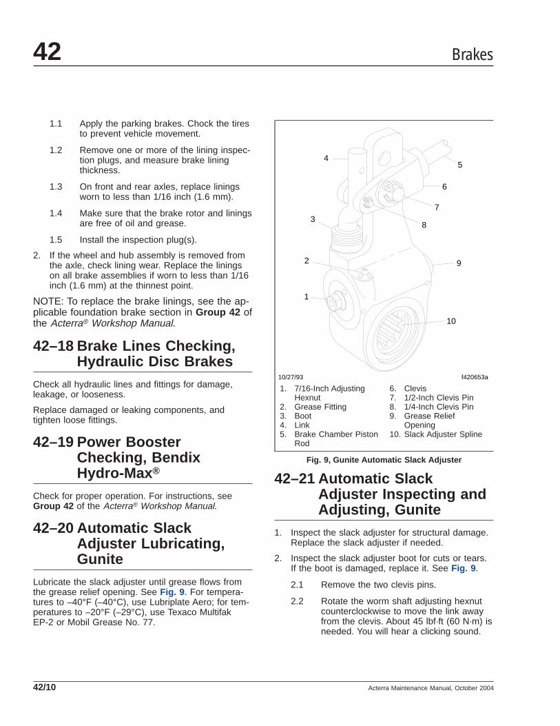
1.1 Apply the parking brakes. Chock the tiresto prevent vehicle movement.
1.2 Remove one or more of the lining inspec-tion plugs, and measure brake liningthickness.
1.3 On front and rear axles, replace liningsworn to less than 1/16 inch (1.6 mm).
1.4 Make sure that the brake rotor and liningsare free of oil and grease.
1.5 Install the inspection plug(s).
2. If the wheel and hub assembly is removed fromthe axle, check lining wear. Replace the liningson all brake assemblies if worn to less than 1/16inch (1.6 mm) at the thinnest point.
NOTE: To replace the brake linings, see the ap-plicable foundation brake section in Group 42 ofthe Acterra® Workshop Manual.
42–18 Brake Lines Checking,Hydraulic Disc Brakes
Check all hydraulic lines and fittings for damage,leakage, or looseness.
Replace damaged or leaking components, andtighten loose fittings.
42–19 Power BoosterChecking, BendixHydro-Max ®
Check for proper operation. For instructions, seeGroup 42 of the Acterra® Workshop Manual.
42–20 Automatic SlackAdjuster Lubricating,Gunite
Lubricate the slack adjuster until grease flows fromthe grease relief opening. See Fig. 9 . For tempera-tures to –40°F (–40°C), use Lubriplate Aero; for tem-peratures to –20°F (–29°C), use Texaco MultifakEP-2 or Mobil Grease No. 77.
42–21 Automatic SlackAdjuster Inspecting andAdjusting, Gunite
1. Inspect the slack adjuster for structural damage.Replace the slack adjuster if needed.
2. Inspect the slack adjuster boot for cuts or tears.If the boot is damaged, replace it. See Fig. 9 .
2.1 Remove the two clevis pins.
2.2 Rotate the worm shaft adjusting hexnutcounterclockwise to move the link awayfrom the clevis. About 45 lbf·ft (60 N·m) isneeded. You will hear a clicking sound.
f420653a
1
2
3
45
6
7
8
10
9
10/27/93
1. 7/16-Inch AdjustingHexnut
2. Grease Fitting3. Boot4. Link5. Brake Chamber Piston
Rod
6. Clevis7. 1/2-Inch Clevis Pin8. 1/4-Inch Clevis Pin9. Grease Relief
Opening10. Slack Adjuster Spline
Fig. 9, Gunite Automatic Slack Adjuster
Brakes42
Acterra Maintenance Manual, October 200442/10

Remove the old boot from the link.
2.3 Install a new boot on the link, heavy sec-tion down. Be careful not to damage theboot.
2.4 Seat the boot so that the bottom of theboot is in the boot insert, and the top is inthe groove of the link.
2.5 Rotate the adjusting hexnut clockwiseuntil the 1/4-inch hole in the clevis linesup with the hole in the link.
Install the 1/4-inch clevis pin and the cot-ter pin.
2.6 Tap the clevis upward or downward untilthe large hole in the slack adjuster linesup with one in the clevis.
Install the 1/2-inch clevis and the cotterpin.
WARNINGMake sure both clevis pins are installed. Failure todo so will cause the slack adjuster to work incor-rectly, which could lead to loss of braking control.This could result in an accident causing personalinjury or property damage.
3. Check for correct chamber stroke.
3.1 With the brakes fully released, use a rulerto measure the distance from the bottomof the brake chamber to the center of thelarge clevis pin. See Fig. 10 .
3.2 Build air pressure to at least 85 psi (585kPa). Apply the brakes, then measure thedistance from the bottom of the brakechamber to the center of the large clevispin. See Fig. 10 . The difference betweenthe measurements is the brake chamberstroke.
Compare this measurement with thoseshown in Table 4 .
4. If the brake chamber stroke exceeds the mea-surements shown in Table 4 , check the founda-tion brakes for problems such as worn cams,bushings, pins and rollers, or broken springs.Repair or replace as needed. For instructions,see Group 42 of the Acterra® Workshop Manual.
Maximum Allowable Brake Chamber Stroke, withGunite Automatic Slack Adjusters
Chamber Size Maximum Allowable Stroke
12 1-3/8 inches (35 mm)
16
1-3/4 inches (44 mm)20
24
24 (long stroke)2 inches (51 mm)
30
Table 4, Maximum Allowable Brake Chamber Stroke,with Gunite Automatic Slack Adjusters
5. If there are no problems with the foundationbrakes, manually adjust the slack adjuster asfollows:
5.1 Turn the adjusting hexnut three-quartersof a turn counterclockwise. See Fig. 9 .
5.2 Keeping the wrench on the adjusting hex-nut, have someone apply the brakes sev-eral times while you watch the hexnut. Itshould turn clockwise. If it does not, re-place the slack adjuster.
f420434b
B
A
09/27/94
A. With the brakes released, measure this distance.B. With the brakes applied, measure this distance.
Fig. 10, Brake Stroke Check, Gunite Automatic SlackAdjuster
Brakes 42
Acterra Maintenance Manual, October 2004 42/11

NOTE: The adjusting hexnut will turn insmall steps. You will not be able to see itturn very well without a wrench on it.
5.3 Check the counterclockwise torque of theadjusting hexnut. The torque should begreater than 15 lbf·ft (20 N·m). If it is not,replace the slack adjuster.
42–22 Automatic SlackAdjuster Lubricating,Haldex
Lubricate a Haldex automatic slack adjuster at thegrease fitting with any extreme-pressure NLGI Grade1 or Grade 2 grease if the operating temperature is–20°F (–29°C) and above. If the operating tempera-ture is below –20°F (–29°C), use a low-temperatureextreme-pressure grease.
42–23 Bosch Rail-SlideHydraulic Brake CaliperLubricating
NOTE: This procedure is only for vehiclesequipped with Bosch rail-slide hydraulic brakecalipers.
IMPORTANT: After the vehicle is put into ser-vice, lubricate the calipers every 6 months orevery 18,000 miles (28 800 km), whichevercomes first.
1. Park the vehicle on a level surface. Shut downthe engine, set the parking brake, and chock thefront or the rear tires, depending on which axleyou are working on.
2. Raise the vehicle off of the ground and securelysupport it with jack stands.
3. Remove the wheel from each wheel end. Forinstructions, see Group 40 of the Acterra® Work-shop Manual.
4. Place a stool near the axle to rest the caliperupon after the caliper is removed.
5. Remove the key-retaining fastener from the an-chor plate. See Fig. 11 .
6. Using a hammer and drift, carefully drive out thekey and spring. See Fig. 12 . Be careful not tonick the anchor plate rail.
7. Insert a large flat-bladed screwdriver through thecaliper vent window and into the rotor fins. Prythe caliper outward; this will push the pistonsback slightly into the caliper, making removaleasier.
1
2
3 4
5
6
f420565a10/28/94
1. Caliper2. Wear Shim3. Spring
4. Fastener5. Key6. Anchor Plate
Fig. 11, Anchor Plate and Key Fastener
f420546
1
23
4
5
608/11/93
1. Key2. Spring3. Anchor Plate Upper
Rail
4. Rotor5. Outboard Brake Pad6. Caliper Housing
Fig. 12, Drive Out the Key and Spring
Brakes42
Acterra Maintenance Manual, October 200442/12

8. Grasp the caliper, swing it out and lift it from theanchor plate. Rest the caliper on the stool. Forease of removal, swing the caliper on the for-ward anchor plate torque rail (the large one op-posite the key and spring rail).
9. Carefully remove the brake pads to avoid dam-aging or getting grease on the pad faces. Setthem aside.
10. Using brake cleaner or alcohol, remove oldgrease from the caliper V-ways, the anchor platerails, and the shoe slots. See Fig. 11 and Fig.13. Also clean the key and spring.
11. Using a wire brush or wire wheel, remove anyremaining debris from the V-ways, rails, shoeslots, key and spring.
12. Apply two level teaspoons of Aeroshell Grade 5(ES1246) grease on each side of the assembly.Apply it evenly along the full length of the V-waygroove and anchor plate rail, and apply one levelteaspoon evenly on both sides of the key andspring. After the caliper is installed, pack any ac-cumulation of grease at each end of the rail andalong the top of the rail or key at the V-way.
13. Being careful not to get grease or dirt on the padface, install each brake pad.
14. Grasp the caliper firmly, rest the V-ways on theforward anchor plate torque rail (the large rail)and swing the caliper into place. Make sure thatthe brake hose is not twisted. Do not get greaseon the pad faces or rotor surfaces.
15. With the caliper installed and firmly seated onthe forward rail (large rail), position the key and
spring between the caliper V-way and the anchorrail from the inboard end of the anchor rail.
16. Carefully drive the key and spring into place. In-stall the key-retaining fastener and torque 12 to18 lbf·ft (16 to 24 N·m).
17. Install the wheels. For instructions, see Group40 of the Acterra® Workshop Manual.
18. Before moving the vehicle, press the brake pedalseveral times to bring the pistons back to thenormal position.
19. Raise the vehicle, remove the jack stands, andlower the vehicle to the ground.
20. Remove the chocks from the tires.
21. Test drive the vehicle and ensure that the brakesoperate properly.
f420595a10/28/94
1
2
1. V-Ways2. Bleeder Fitting
Fig. 13, Caliper V-Ways
Brakes 42
Acterra Maintenance Manual, October 2004 42/13

Title of Maintenance Operation (MOP) MOP Number
Drag Link Lubricating . . . . . . . . . . . . . . . . . . . . . . . . . . . . . . . . . . . . . . . . . . . . . . . . . . . . . . . . . . . . . . . 46–02
Power Steering Gear Lubricating. . . . . . . . . . . . . . . . . . . . . . . . . . . . . . . . . . . . . . . . . . . . . . . . . . . . . . . 46–05
Power Steering Reservoir Fluid Level Checking. . . . . . . . . . . . . . . . . . . . . . . . . . . . . . . . . . . . . . . . . . . . 46–03
Power Steering Reservoir Fluid and Filter Changing . . . . . . . . . . . . . . . . . . . . . . . . . . . . . . . . . . . . . . . . 46–04
Steering Driveline Lubricating . . . . . . . . . . . . . . . . . . . . . . . . . . . . . . . . . . . . . . . . . . . . . . . . . . . . . . . . . 46–01
Steering 46Index, Alphabetical
Acterra Maintenance Manual, July 2004

46–01 Steering DrivelineLubricating
Wipe the grease fittings clean. See Fig. 1 . Using apressure gun, apply a lithium-based grease (NLGIgrade 2) sparingly to the universal joints and slip-jointsplines.
46–02 Drag Link Lubricating1. Using a clean rag, wipe the dirt from both grease
fittings on the drag link. See Fig. 2 .
2. Using a pressure gun, apply multipurpose chas-sis grease at the grease fittings until old greaseis forced out of the socket.
NOTE: Use multipurpose chassis grease NLGIgrade 1 (6% 12-hydroxy lithium stearate grease)or NLGI grade 2 (8% 12-hydroxy lithium stear-ate grease). Grade 2 chassis grease is pre-ferred.
1
2
34
51
6
6
10/05/94 f460516a
7
7
1. Pinch Bolt2. Universal Joint Shaft3. Bushing
4. Boot5. Boot Retainer
6. Prevailing Torque Locknut7. Grease Fitting
Fig. 1, Steering Driveline
Steering 46
Acterra Maintenance Manual, July 2004 46/1

46–03 Power SteeringReservoir Fluid LevelChecking
Metal Ventra Reservoir1. Turn off the engine, apply the parking brakes,
and chock the tires.
2. Open the hood.
3. Clean around the power steering reservoir fill capwith a clean rag, then remove the dipstick.
WARNINGFill only with approved clean fluid. Do not mixfluid types. Any mixture or any unapproved fluidcould lead to seal deterioration and leaks. Fluidleakage could cause loss of power steering assist,possibly resulting in personal injury and propertydamage.
4. With the power steering fluid at operating tem-perature, check the fluid level on the dipstick. Ifbelow the ADD mark, add enough fluid to bringthe level up to the FULL mark on the dipstick.Use Dexron® III automatic transmission fluid(ATF) in the power steering reservoir.
5. Install the fill cap on the power steering reservoir.
6. Close the hood, and remove the chocks from thetires.
Nelson ReservoirNOTE: If the power steering reservoir in the ve-hicle looks like the reservoir shown in Fig. 3 , usethe following procedure.
1. Turn off the engine, apply the parking brakes,and chock the tires.
2. Open the hood.
3. With the engine cool, the level should be be-tween MIN COLD and MAX HOT lines with theengine off. Add or remove fluid as necessary tobring the fluid level to the line between the MINCOLD and MAX HOT lines. Use only Dexron® IIIautomatic transmission fluid.
4. With the engine hot, the fluid level should be atthe MAX HOT line with the engine off.
5. Add or remove fluid as necessary to bring thefluid level to the MAX HOT line. Use onlyDexron® III automatic transmission fluid.
6. Close the hood, and remove the chocks from thetires.
f46092610/05/94
1 2
1. Grease Fitting2. Drag Link (pitman arm end shown)
Fig. 2, Steering Drag Link
07/09/98 f461670
1
2
4
5
6
3
1. Fill Cap2. Filter Spring3. Filter Top Plate
4. Clamp5. Filter6. Reservoir Cover
Fig. 3, Nelson Power Steering Reservoir and Filter
Steering46
Acterra Maintenance Manual, July 200446/2

Plastic Ventra ReservoirNOTE: If the power steering reservoir in the ve-hicle looks like the reservoir shown in Fig. 4 , usethe following procedure.
1. Turn off the engine, apply the parking brakes,and chock the tires.
2. Open the hood.
3. With the engine cool, the fluid level should bebetween the MIN COLD and MAX HOT lines withthe engine off. Add or remove fluid as necessaryto bring the fluid level to the line between theMIN COLD and MAX HOT lines. Use onlyDexron® III automatic transmission fluid.
4. With the engine hot, the fluid level should be atthe MAX HOT line with the engine off. Add orremove fluid as necessary to bring the fluid levelto the MAX HOT line. Use only Dexron® III auto-matic transmission fluid.
5. Close the hood, and remove the chocks from thetires.
46–04 Power SteeringReservoir Fluid andFilter Changing
Metal Ventra Reservoir1. Turn off the engine, apply the parking brakes,
and chock the tires.
2. Open the hood.
3. Remove the fill cap, nut, and cover from thesteering reservoir.
4. Disconnect the hose, between the reservoir andthe steering gear, from the reservoir. Then drainthe reservoir in a drain pan, and cap the reser-voir port.
5. Lift out the spring and filter element.
6. Thoroughly clean the reservoir with a lint-freecloth.
7. Install a new filter element, and position thespring on top of the filter element.
8. Fill the reservoir with Dexron® III automatic trans-mission fluid.
WARNINGFill only with approved clean fluid. Do not mixfluid types. Any mixture or any unapproved fluidcould lead to seal deterioration and leaks. Fluidleakage could cause loss of power steering assist,possibly resulting in personal injury and propertydamage.
9. Place the end of the hose in the drain pan. Donot start the engine while draining the sys-tem. Raise the front of the vehicle with a floorjack and support it with jack stands. Have some-one turn the steering wheel to full lock left andright, and capture the fluid flowing from the hosein the drain pan. Add fluid to the reservoir, asneeded. Continue turning the steering wheel untilclean power steering fluid flows from the hose.
10. Remove the plug from the reservoir and connectthe hose to the reservoir. Tighten the hose fittingnut finger tight. Then with a wrench, tighten untilthere is firm resistance. Tighten one-sixth turnmore. Do not overtighten.
f461917
1
23
4
10/19/2001
1. Power Steering Reservoir2. Retaining Ring3. Filter Cover4. Return Hose
Fig. 4, Power Steering Reservoir
Steering 46
Acterra Maintenance Manual, July 2004 46/3

Remove the jack stands and lower the vehicle.
11. Fill the reservoir with ATF as needed. Start theengine and let it idle. Have someone turn thesteering wheel from lock to lock until no bubblesare seen in the reservoir. Turn off the engine.
12. Install a new cover gasket, the cover, and nut.Tighten the nut 28 lbf·ft (38 N·m). Install the fillcap.
13. Start the engine and check the power steeringreservoir fluid level. If the fluid level is low, addATF to bring the level up to the FULL mark onthe dipstick.
14. Close the hood and remove the chocks from thetires.
Nelson Reservoir
WARNINGFill only with approved clean fluid. Do not mixfluid types. Failure to use the proper fluid couldcause seal deterioration and leaks. Fluid leakscould eventually cause loss of power steering as-sist. This could lead to an accident resulting inpersonal injury or property damage. Wear eye pro-tection when changing the fluid and filter.
NOTE: If the power steering reservoir in the ve-hicle looks like the reservoir shown in Fig. 3 , usethe following procedure.
1. Turn off the engine, apply the parking brakes,and chock the tires.
2. Open the hood.
3. Place a drain pan under the reservoir, and re-move the steering gear-to-reservoir return hoseat the reservoir. Drain the steering fluid into thedrain pan and dispose of the fluid properly. Plugthe return line fitting on the reservoir.
4. Loosen the clamp and remove the cover alongwith the filter spring and the filter top plate. SeeFig. 3 .
NOTE: Always replace the reservoir filter whenchanging the fluid.
5. Remove the filter. It may be necessary to wigglethe filter to remove it from its base. Do not usepliers to aid in removal of the filter; pliers could
cause metal chips to enter the steering system.Clean the inside of the reservoir using a lint-freecloth.
IMPORTANT: Do not start the engine whiledraining the system.
6. Place the disconnected end of the steering gear-to-reservoir hose in a drain pan. Raise the frontof the vehicle with a floor jack and support it withjack stands. Have someone turn the steeringwheel to full lock left and right. Capture the fluidflowing from the hose in a drain pan. Add fluid tothe reservoir as needed. When clean fluid flowsfrom the hose into the drain pan, remove theplug from the reservoir and reconnect the steer-ing gear-to-reservoir hose to the reservoir. Re-move the jack stands and lower the vehicle.
7. With the larger opening at the top, install a newfilter in the reservoir.
8. Clean the reservoir cover and gasket. Inspect theO-ring and the cover for cracks, deformities, ordamage. Replace the gasket seal or cover asneeded.
9. Install the reservoir cover along with the springand the top plate. Make sure the center of thetop plate fits into the opening at the top of thefilter.
10. Place the clamp over the flanges of the coverand shell assembly, then tighten the clamp 25 to30 lbf·ft (35 to 40 N·m).
11. Fill the reservoir with Dexron® III automatic trans-mission fluid to the FULL COLD mark.
12. Start the engine and operate it at idle. Turn thesteering wheel to full lock left and right to adjustthe fluid level and remove any existing air fromthe power steering pump and gear. Check thefluid level again. Add fluid as needed. The sys-tem is properly bled when the steering pumpdoes not labor when turning the wheel.
13. Check for leaks in the system and repair asneeded. Fill the reservoir as needed.
14. Turn off the engine, close the hood, and removethe chocks from the tires.
Steering46
Acterra Maintenance Manual, July 200446/4

Plastic Ventra ReservoirNOTE: If the power steering reservoir in the ve-hicle looks like the reservoir shown in Fig. 4 , usethe following procedure.
1. Turn off the engine, apply the parking brakes,and chock the tires.
2. Open the hood.
3. Place a drain pan under the power steering res-ervoir.
4. Remove the retaining ring from the reservoir.See Fig. 4 .
5. Remove the filter and filter cover from the reser-voir. Drain the fluid from the filter into the drainpan. Leave the filter hanging over the drain pan.
6. Remove the bolts, nuts, and washers that attachthe reservoir to the mounting bracket. Drain thefluid from the reservoir, but do not remove thesupply line to the reservoir.
7. Using bolts, nuts, and washers, attach the reser-voir to the mounting bracket.
8. Fill the reservoir with Dexron® III automatic trans-mission fluid to the line between the MIN COLDand MAX HOT lines. See Fig. 4 .
9. Raise the front of the vehicle and support it withjack stands.
10. Start the engine and operate it at idle. Turn thesteering wheel from full left to full right severaltimes until clean fluid starts flowing from thesteering filter. Add fluid to the reservoir to main-tain the fluid level between the MIN COLD andMAX HOT lines.
11. Shut down the engine and install the filter andfilter cover in the reservoir. Make sure that thegasket under the filter cover is not damaged. Ifthe gasket is damaged, replace it. Install the gas-ket on the reservoir.
12. Attach the retaining ring to the reservoir to se-cure the filter and filter cover.
13. Start the engine and check that the fluid level isbetween the MIN COLD and MAX HOT lines.Add more fluid if needed.
14. Raise the vehicle, remove the jack stands, andlower the vehicle.
15. Close the hood, and remove the chocks from thetires.
46–05 Power Steering GearLubricating
1. Wipe off debris from the grease fitting. SeeFig. 5 .
2. Using a hand-type grease gun, apply multipur-pose chassis grease until the grease starts com-ing out of the sector shaft dirt and water seal.
f460515a
1
04/13/93
1. Sector Shaft Grease Fitting
Fig. 5, Sector Shaft, TRW TAS Series
Steering 46
Acterra Maintenance Manual, July 2004 46/5

Title of Maintenance Operation (MOP) MOP Number
Fuel Tank Draining and Vent Checking . . . . . . . . . . . . . . . . . . . . . . . . . . . . . . . . . . . . . . . . . . . . . . . . . . 47–01
Fuel 47Index, Alphabetical
Acterra Maintenance Manual, March 2000

47–01 Fuel Tank Draining andVent Checking
Remove the plug or open the drain valve at the bot-tom of the fuel tank, and allow the tank to drain untilall traces of water and sediment have disappeared;install the plug or close the drain valve.
On earlier vehicles with a screw-on fuel cap, removethe fuel cap and clean it with solvent. Make sure thefuel cap vent is open. Install the cap.
On vehicles with a quarter-turn fuel cap, check to besure the vent line at the inboard side of the fuel tankis clean and not plugged.
Fuel 47
Acterra Maintenance Manual, March 2000 47/1

Title of Maintenance Operation (MOP) MOP Number
Exhaust System Inspecting (Noise Emission Controls) . . . . . . . . . . . . . . . . . . . . . . . . . . . . . . . . . . . . . . . 49-01
Exhaust 49Index, Alphabetical
Acterra Maintenance Manual, March 2000

49-01 Exhaust SystemInspecting (NoiseEmission Controls)
NOTE: In addition to the maintenance interval inthis manual, inspect the exhaust system if thevehicle has a noticeable increase in noise levelat any time. Replace parts that show leakage,wear, or damage.
1. Check the muffler body, muffler outlet stack, muf-fler shield, and inlet tubes, for leakage, dents,corrosion, or holes in the muffler.
2. Inspect the exhaust pipe for leakage, wear, ordamage; replace with new parts, if needed. Donot reuse wide-band clamps. Once a clamp isremoved, it must be replaced.
2.1 On Caterpillar and Cummins engines,check for leakage at the V-type clampthat attaches the exhaust pipe to the tur-bocharger exhaust outlet. If leakage ex-ists, tighten the nut on the V-type clamp85 lbf·in (940 N·cm). If leakage persists,install a new V-band coupling.
2.2 On Mercedes-Benz MBE900 engines,check the tightness of the fasteners thatattach the exhaust pipe to the exhaustflange (see Fig. 1 ). If needed, tighten thefasteners 33 lbf·ft (45 N·m) for Mercedes-Benz MBE900 engines.
3. Check for leakage at each wide-band exhaustclamp (see Fig. 2 ). If leakage exists, tighten thenuts 40 to 60 lbf·ft (54 to 81 N·m). If leakage per-sists, install a new wide-band exhaust clamp.See Group 49 of the Acterra® Workshop Manualfor instructions.
f490032a10/05/94
A
A. Check the Tightness of These Fasteners
Fig. 1, Typical Exhaust-Pipe to Exhaust-FlangeFasteners
f490005a10/05/94
Fig. 2, Wide-Band Exhaust Clamp
Exhaust 49
Acterra Maintenance Manual, March 2000 49/1

Title of Maintenance Operation (MOP) MOP Number
Coolant Level Sensor Cleaning. . . . . . . . . . . . . . . . . . . . . . . . . . . . . . . . . . . . . . . . . . . . . . . . . . . . . . . . 54–02
Electrical System Checking. . . . . . . . . . . . . . . . . . . . . . . . . . . . . . . . . . . . . . . . . . . . . . . . . . . . . . . . . . . 54–01
Electrical, Instruments, and Controls 54Index, Alphabetical
Acterra Maintenance Manual, March 2000
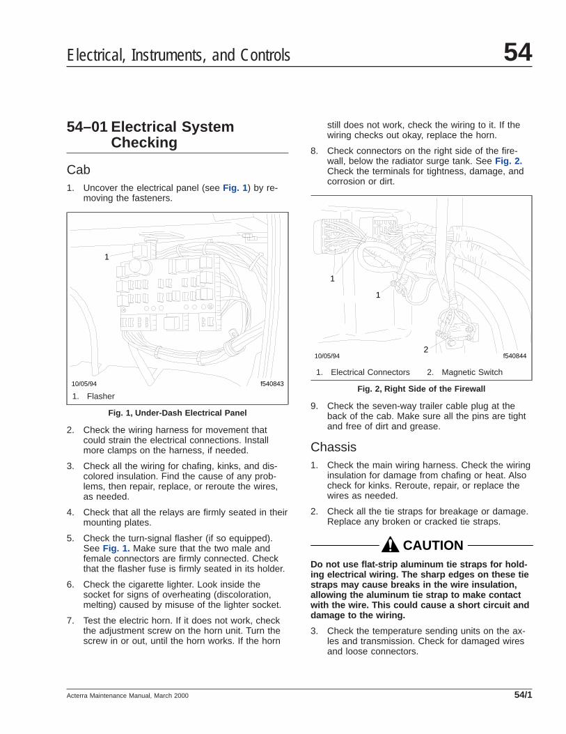
54–01 Electrical SystemChecking
Cab1. Uncover the electrical panel (see Fig. 1 ) by re-
moving the fasteners.
2. Check the wiring harness for movement thatcould strain the electrical connections. Installmore clamps on the harness, if needed.
3. Check all the wiring for chafing, kinks, and dis-colored insulation. Find the cause of any prob-lems, then repair, replace, or reroute the wires,as needed.
4. Check that all the relays are firmly seated in theirmounting plates.
5. Check the turn-signal flasher (if so equipped).See Fig. 1. Make sure that the two male andfemale connectors are firmly connected. Checkthat the flasher fuse is firmly seated in its holder.
6. Check the cigarette lighter. Look inside thesocket for signs of overheating (discoloration,melting) caused by misuse of the lighter socket.
7. Test the electric horn. If it does not work, checkthe adjustment screw on the horn unit. Turn thescrew in or out, until the horn works. If the horn
still does not work, check the wiring to it. If thewiring checks out okay, replace the horn.
8. Check connectors on the right side of the fire-wall, below the radiator surge tank. See Fig. 2.Check the terminals for tightness, damage, andcorrosion or dirt.
9. Check the seven-way trailer cable plug at theback of the cab. Make sure all the pins are tightand free of dirt and grease.
Chassis1. Check the main wiring harness. Check the wiring
insulation for damage from chafing or heat. Alsocheck for kinks. Reroute, repair, or replace thewires as needed.
2. Check all the tie straps for breakage or damage.Replace any broken or cracked tie straps.
CAUTIONDo not use flat-strip aluminum tie straps for hold-ing electrical wiring. The sharp edges on these tiestraps may cause breaks in the wire insulation,allowing the aluminum tie strap to make contactwith the wire. This could cause a short circuit anddamage to the wiring.
3. Check the temperature sending units on the ax-les and transmission. Check for damaged wiresand loose connectors.
f54084310/05/94
1
1. Flasher
Fig. 1, Under-Dash Electrical Panel
f54084410/05/94
1
2
1
1. Electrical Connectors 2. Magnetic Switch
Fig. 2, Right Side of the Firewall
Electrical, Instruments, and Controls 54
Acterra Maintenance Manual, March 2000 54/1

54–02 Coolant Level SensorCleaning
1. Drain enough coolant from the radiator to exposethe coolant level sensor.
2. Disconnect wire 173 from the sensor in the ra-diator surge tank. Remove the sensor from thesurge tank.
3. Using a fine-grit sandpaper, clean the sensor un-til the metal is exposed. Clean the tapped holewith a wire brush.
4. Install the sensor (do not seal the sensor threadswith tape), and reconnect wire 173. Fill the cool-ing system to the proper level.
5. Start the engine. The LOW WTR light and warn-ing buzzer should be off. If the light and buzzerare off, the sensor is okay. If the light and buzzerare on, replace the sensor.
Electrical, Instruments, and Controls54
Acterra Maintenance Manual, March 200054/2

Title of Maintenance Operation (MOP) MOP Number
Weatherstrip, Door Latch, and Door Hinge Lubricating. . . . . . . . . . . . . . . . . . . . . . . . . . . . . . . . . . . . . . . 72–01
Doors 72Index, Alphabetical
Acterra Maintenance Manual, March 2000

72–01 Weatherstrip, DoorLatch, and Door HingeLubricating
Lightly coat door weatherstrips with a lubricant that issafe (as recommended by the lubricant manufac-turer) on rubber.
Apply a few drops of light engine oil, or spray a lightcoating of silicone lubricant on the door latch mecha-nism. This will help reduce noise and wear. Wipe offany excess oil or silicone lubricant.
Lubricate door hinges by spraying them with a lightcoating of silicone lubricant.
Always lubricate new cab-door hinges at installation.
Doors 72
Acterra Maintenance Manual, March 2000 72/1
Title of Maintenance Operation (MOP) MOP Number
Air Conditioner Inspecting. . . . . . . . . . . . . . . . . . . . . . . . . . . . . . . . . . . . . . . . . . . . . . . . . . . . . . . . . . . . 83–01
HVAC Air Filter Replacing. . . . . . . . . . . . . . . . . . . . . . . . . . . . . . . . . . . . . . . . . . . . . . . . . . . . . . . . . . . . 83–02
Heater and Air Conditioner 83Index, Alphabetical
Acterra Maintenance Manual, March 2003

83–01 Air ConditionerInspecting
WARNINGWear eye protection, gloves, and protective cloth-ing when working on the air conditioning system.Leaking refrigerant from a damaged hose or linecould cause blindness or serious skin burns.
Preliminary Checks1. Park the vehicle on a level surface, apply the
parking brakes, and chock the tires.
2. Check the appearance of the air conditionercompressor pulley assembly. If the friction sur-face of the pulley shows signs of excessivegrooving due to belt slippage, replace both thepulley and the drive plate. Visually inspect therefrigerant compressor drive belt for damage,and check that the belt is set at the proper ten-sion. Also check the tightness of the compressormounting fasteners. For instructions and torquevalues, see Group 01 of the Acterra® WorkshopManual.
3. Inspect the drive plate. If the friction surface ofthe drive plate shows visible signs of damagedue to excessive heat, replace the drive plateand pulley assembly. in Group 83 of the Ac-terra® Workshop Manual for removal and installa-tion procedures.
4. On a Sanden refrigerant compressor, use afeeler gauge to check that the drive plate clutchclearance is 0.016 to 0.03 inch (0.4 to 0.8 mm).See Fig. 1 . If the drive plate clutch requires ad-justment, see Group 83 of the Acterra® Work-shop Manual.
On a Climate Control refrigerant compressor,place a feeler gauge between the air conditionercompressor clutch and the pulley to check thecompressor clutch clearance. Drive plate to pul-ley clearance is 0.02 to 0.03 inch (0.6 to 0.8mm). If the clearance is not correct, see Group83 of the Acterra® Workshop Manual
5. Inspect the compressor clutch coil wire. Checkthat the connector is not damaged or loose. Re-place the wire if it is damaged.
6. Check the overall condition of the air conditioninghoses. Look for cracks, cuts, and abrasions onthe hoses. Replace damaged hoses. See Group83 of the Acterra® Workshop Manual for replace-ment instructions. Also, check for loose fittingson all air conditioning components.
7. Check for a buildup of road debris on the con-denser fins. See Group 83 of the Acterra® Work-shop Manual for cleaning instructions.
83–02 HVAC Air FilterReplacing
The air filter must be replaced every six months, re-gardless of mileage, to permit proper operation of theHVAC system.
IMPORTANT: When replacing the air filter, useonly a Sterling-approved air filter.
1. Turn off the engine, apply the parking brakes,and chock the tires.
2. Open the hood.
3. Remove the screws that attach the filter cover tothe filter housing. See Fig. 2 .
4. Remove the filter from the housing.
5. Install a new filter in the housing.
6. Using screws, attach the filter cover to the hous-ing.
7. Close the hood.
8. Remove the chocks from the tires.
08/25/94 f830641
Fig. 1, Drive Plate Clearance Inspection
Heater and Air Conditioner 83
Acterra Maintenance Manual, March 2003 83/1

02/17/2003 f831564
11
2
1. Screw 2. Filter Cover
Fig. 2, Air Filter Replacement
Heater and Air Conditioner83
Acterra Maintenance Manual, March 200383/2