2-wire programmable transmitter tt521
TRANSCRIPT

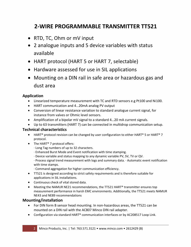
2-WIRE PROGRAMMABLE TRANSMITTER TT521

Minco Products, Inc. | Tel: 763.571.3121 • www.minco.com • 2612429 (B) ...... 1
2-WIRE PROGRAMMABLE TRANSMITTER TT521
CONTENTS Application ......................................................................................................... 2
Technical Characteristics ..................................................................................... 2
Mounting / Installation ....................................................................................... 2
Applications ........................................................................................................ 3
Order: TT521 ....................................................................................................... 4
Technical Data .................................................................................................... 4
Changing the HART Protocol Version .................................................................. 8
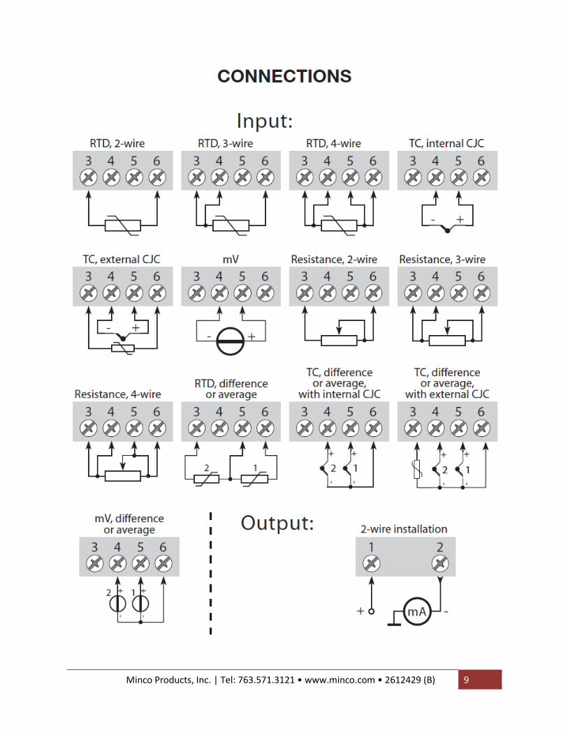
Connections ........................................................................................................ 9
Programming .................................................................................................... 10
Multi-Drop Mode .............................................................................................. 12
Mounting of sensor wires ................................................................................. 12
Appendix .......................................................................................................... 13
ATEX Installation Drawing – TT521 .............................................................. 13
IECEx Installation Drawing .......................................................................... 15
Installation Drawing 5300Q502 ................................................................... 17
CSA Installation Drawing ............................................................................. 19
2 Minco Products, Inc. | Tel: 763.571.3121 • www.minco.com • 2612429 (B)
2-WIRE PROGRAMMABLE TRANSMITTER TT521
• RTD, TC, Ohm or mV input
• 2 analogue inputs and 5 device variables with status
available
• HART protocol (HART 5 or HART 7, selectable)
• Hardware assessed for use in SIL applications
• Mounting on a DIN rail in safe area or hazardous gas and
dust area
Application
• Linearized temperature measurement with TC and RTD sensors e.g Pt100 and Ni100.
• HART communication and 4…20mA analog PV output
• Conversion of linear resistance variation to standard analogue current signal, for instance from valves or Ohmic level sensors.
• Amplification of a bipolar mV signal to a standard 4…20 mA current signals.
• Up to 63 transmitters (HART 7) can be connected in multidrop communication setup.
Technical characteristics • HART® protocol revision can be changed by user configuration to either HART® 5 or HART® 7
protocol. • The HART® 7 protocol offers:
∙ Long Tag numbers of up to 32 characters. ∙ Enhanced Burst Mode and Event notification with time stamping. ∙ Device variable and status mapping to any dynamic variable PV, SV, TV or QV. ∙ Process signal trend measurement with logs and summary data. ∙ Automatic event notification with time stamps. ∙ Command aggregation for higher communication efficiency.
• TT521 is designed according to strict safety requirements and is therefore suitable for applications in SIL installations.
• Continuous check of vital stored data. • Meeting the NAMUR NE21 recommendations, the TT521 HART® transmitter ensures top
measurement performance in harsh EMC environments. Additionally, the TT521 meets NAMUR NE43 and NE89 recommendations
Mounting/installation • For DIN form B sensor head mounting. In non-hazardous areas, the TT521 can be
mounted on a DIN rail with the AC807 Minco DIN rail adapter.
• Configuration via standard HART® communication interfaces or by AC208517 Loop Link.

Minco Products, Inc. | Tel: 763.571.3121 • www.minco.com • 2612429 (B) ...... 3

4 Minco Products, Inc. | Tel: 763.571.3121 • www.minco.com • 2612429 (B)
To Order TT521:
Technical data Environmental conditions: Specifications range ……………………………………………… -40oC to +85oC Calibration temperature ………………………………………. 20…28oC Relative humidity …………………………………………………. <95% RH (non-cond.) Protection degree (encl./terminal) ………………………. IP68/IP00 Mechanical specifications: Dimensions …………………………………………………………… Ø 44 x 20.2 mm Weigh approx. ………………………………………………………. 50 g Max. wire size ………………………………………………………. 1 x1.5 mm2 stranded wire Screw terminal torque ………………………………………….. 0.4 Nm Vibration ………………………………………………………………. IEC 60068-2-6 Test : 2007 2…25 Hz…………………………………………………….. ±1.6 mm
25…100 Hz…………………………………………………. ±4 g

Minco Products, Inc. | Tel: 763.571.3121 • www.minco.com • 2612429 (B) ...... 5
Common electrical specifications: Supply voltage, DC: ATEX, CSA, FM, IECEx & INMETRO ……………. 8.0…30 V Voltage drop ………………………………………………………... 8.0 V Isolation – test / working ……………………………………... 1.5 kVAC / 50 VAC Signal /noise ratio ………………………………………………… > 60 dB Communications interface …………………………………… AC208517 via HART7 Response time (programmable) …………………………… 1…60 s Accuracy
Calibration Type Accuracy
Nominal Pt(.00385) RTD Greater of ±0.18°F / ±0.1°C or ±0.1% of span
Ni RTD Greater of ±0.36°F / ±0.2°C or ±0.1% of span
Non-Pt(.00385) and Ni RTD Elements with >25Ω span
±0.45°F / ±0.25°C
Non-Pt(.00385) and Ni RTD Elements with <25Ω span
±0.9°F / ±0.5°C
Thermocouple Greater of ±1.8F / ±1.0°C or ±0.1% span
Matched RTD See ordering options
TC cold junction compensation...................... < ±1.0°C Max. offset on input signal............................. 50% of selec. max. value EMC immunity influence …………………………………… < ±0.1% of span Extended EMC immunity: NAMUR NE 21, A criterion, burst ………………………. < ±1% of span
6 Minco Products, Inc. | Tel: 763.571.3121 • www.minco.com • 2612429 (B)
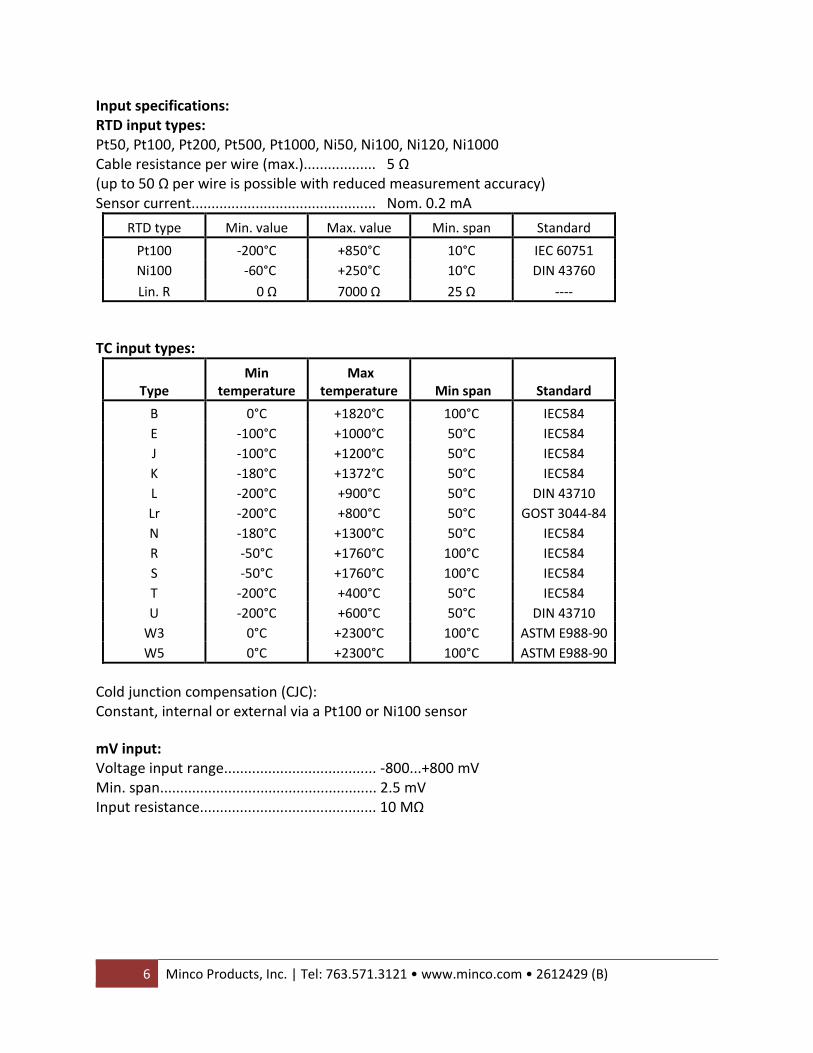
Input specifications: RTD input types: Pt50, Pt100, Pt200, Pt500, Pt1000, Ni50, Ni100, Ni120, Ni1000 Cable resistance per wire (max.).................. 5 Ω (up to 50 Ω per wire is possible with reduced measurement accuracy) Sensor current.............................................. Nom. 0.2 mA
RTD type Min. value Max. value Min. span Standard
Pt100 -200°C +850°C 10°C IEC 60751
Ni100 -60°C +250°C 10°C DIN 43760
Lin. R 0 Ω 7000 Ω 25 Ω ----
TC input types:
Type Min
temperature Max
temperature Min span Standard
B 0°C +1820°C 100°C IEC584
E -100°C +1000°C 50°C IEC584
J -100°C +1200°C 50°C IEC584
K -180°C +1372°C 50°C IEC584
L -200°C +900°C 50°C DIN 43710
Lr -200°C +800°C 50°C GOST 3044-84
N -180°C +1300°C 50°C IEC584
R -50°C +1760°C 100°C IEC584
S -50°C +1760°C 100°C IEC584
T -200°C +400°C 50°C IEC584
U -200°C +600°C 50°C DIN 43710
W3 0°C +2300°C 100°C ASTM E988-90
W5 0°C +2300°C 100°C ASTM E988-90
Cold junction compensation (CJC): Constant, internal or external via a Pt100 or Ni100 sensor
mV input: Voltage input range...................................... -800...+800 mV Min. span...................................................... 2.5 mV Input resistance............................................ 10 MΩ

Minco Products, Inc. | Tel: 763.571.3121 • www.minco.com • 2612429 (B) ...... 7
Output: Signal range ................................................. 4...20 mA Min. signal range ......................................... 16 mA Updating time .............................................. 440 ms
Load resistance ............................................ ≤ (Vsupply - 8) / 0.023 [Ω] Sensor error detection, programmable ....... 3.5...23mA NAMUR NE43 Upscale ................................. 23 mA NAMUR NE43 Downscale ............................ 3.5 mA HART protocol revisions……………………………. HART 5 and HART 7 Approvals: EMC 2004/108/EC........................................ EN 61326-1 EAC TR-CU 020/2011………………………………… EN 61326-1 Marine approval: Det Norske Veritas, Ships & Offshore........... Stand. for Certific. No. 2.4 Ex / I.S.: ATEX 94/9/EC.................................................... KEMA 03ATEX1537 IECEx................................................................. KEM 10.0083 X FM certificate................................................... 2D5A7 CSA certificate.................................................. 1125003 INMETRO certificate......................................... NCC 12.0844 X EAC Ex TR-CU 012/2011………………………………… RU C-DK.GB08.V.00410 Functional Safety: Hardware assessed for use in SIL applications FMEDA report – contact Minco Products, Inc.

8 Minco Products, Inc. | Tel: 763.571.3121 • www.minco.com • 2612429 (B)
Changing the HART protocol version
It is possible to change the unit’s HART protocol revision by using the Temptran Utilities
software and AC205817, or a HART interface. Other HART configuration tools like a handheld
HART Terminal may also be used.
Procedure for using a HART hand-held terminal to change the TT521 from HART 7 to HART 5
(and vice versa)
Change the TT521 from HART 7 to HART 5: Drive the TT521 device Online and enter Device setup – Diag/Service. Select “Write protection” and Write protect by entering “********” (8 stars). Select New password – type “********” (8 stars) and then “HARTREV5” Select Write enable by entering “-CHANGE-” Change the TT521 from HART 5 to HART 7: Drive the TT521 device Online and enter Device setup – Diag/Service. Select “Write protection” and Write protect by entering “********” (8 stars). Select New password – type “********” (8 stars) and then “HARTREV7” Select Write enable by entering “-CHANGE-” Changing the HART protocol version using the Temptran Utilities software and AC205817 NOTE: YOU CANNOT CHANGE BACK TO HART 7 USING TEMPTRAN UTILITIES! A HART TERMINAL MUST BE USED (see above) Switching from HART 7 to HART 5 Select the TT521 product, click the “HART” tab and open the folder “Methods”. Click “Device Password / Write Protection / Protocol…” and select “Change protocol to HART 5” in the pop-up window, then acknowledge by pressing OK.
Minco Products, Inc. | Tel: 763.571.3121 • www.minco.com • 2612429 (B) ...... 9

10 Minco Products, Inc. | Tel: 763.571.3121 • www.minco.com • 2612429 (B)
Programming Temptran Utilities and AC205817 Programmer
• Use Temptran Utilities software to program the TT518, TT519, TT520 & TT521
• Use AC205817
• For programming please refer to the drawing below.
• Not approved for communication with modules installed in hazardous (Ex) areas.

Minco Products, Inc. | Tel: 763.571.3121 • www.minco.com • 2612429 (B) ...... 11
HART Modem For programming, please refer to the drawing below and the help functions in Temptran Utilities.
HART Communicator For programming please refer to the drawing below. To gain access to product-specific commands, a suitable HART communicator must be loaded with the PR electronics A/S DDL driver. This can be ordered either at the HART Communication Foundation or at PR electronics A/S.

12 Minco Products, Inc. | Tel: 763.571.3121 • www.minco.com • 2612429 (B)
Collection of Transmitters in Multidrop Mode The HART communicator of a PC Modem can be connected across AB or BC.
The outputs of maximum 63 transmitters can be connected in parallel for a digital HART 7 communication on 2-wires. Before it is connected, each transmitter must be configured with a unique number from 1 to 63. If 2 transmitters are configured with the same number, both will be excluded. The transmitters must be programmed for multidrop mode (with a fixed output signal of 4 mA). Maximum current in the loop is therefore 252 mA. The communication is either by means of HART communicator or a HART modem. The Temptran Utilities configuration software can configure the individual transmitter for multidrop mode and provide it with a unique polling address.

Minco Products, Inc. | Tel: 763.571.3121 • www.minco.com • 2612429 (B) ...... 13
Appendix
ATEX Installation Drawing 5335QA01 For safe installation of TT521 the following must be observed. The module shall only be installed by qualified personnel who are familiar with the national and international laws, directives and standards that apply to this area. Year of manufacture can be taken from the first two digits on the serial number.
ATEX Certificate KEMA 03ATEX 1537 Marking II 1 G Ex ia IIC T6…T4 Ga
II 1 D Ex ia IIIC Da II M1 Ex ia I Ma
Standards EN60079-0 : 2012, EN60079-11 : 2012, EN60079-26 : 2007

14 Minco Products, Inc. | Tel: 763.571.3121 • www.minco.com • 2612429 (B)
Installation notes: General installation instructions
The sensor circuit is not infallibly galvanic isolated from the supply output circuit. However, the galvanic isolation between the circuits is capable of withstanding a test voltage of 500Vac during 1 minute.
If the enclosure is made of aluminum, it must be installed such, that even in the event of rare incidents, ignition sources due to impact and friction, sparks are excluded. If the enclosure is made of non-metallic materials or painted metals electrostatic charging shall be avoided.
For installation in a potentially explosive gas atmosphere, the following instructions apply:
The transmitter shall be mounted in an enclosure form B according to DIN43729 or equivalent that is providing a degree of protection of at least IP20 according to EN60529 that is suitable for the application and correctly installed.
For installation in a potentially explosive dust atmosphere, the following instructions apply:
The transmitter shall be mounted in a metal enclosure form B according to DIN43729 or equivalent, that is providing a degree of protection of at least IP6X according to EN60529 that is suitable for the application and correctly installed. Cable entries and blanking elements shall be used that are suitable for the application and correctly installed.
For installation in mines the following instructions apply:
The transmitter shall be mounted in a metal enclosure that is providing a degree of protection of at least IP6X according to EN60529, and is suitable for the application and correctly installed. Cable entries and blanking elements shall be used that are suitable for the application and correctly installed. If the enclosure is made of aluminum, it must be installed such, that even in the event of rare incidents, ignition sources due to impact and friction, sparks are excluded. If the enclosure is made of non-metallic materials or painted metals electrostatic charging shall be avoided. The enclosure shall not contain by mass more than a) 15 % in total of aluminum, magnesium, titanium and zirconium, and b) 7,5 % in total of magnesium, titanium and zirconium.

Minco Products, Inc. | Tel: 763.571.3121 • www.minco.com • 2612429 (B) ...... 15
IECEx Installation drawing For save installation of the TT521 the following must be observed. The module shall only be installed by qualified personnel who are familiar with the national and international laws, directives and standards that apply to this area. Year of manufacture can be taken from the first two digits in the serial number.
IECEx Certificate IECEx KEM 10.0083X Marking Ex ia IIC T6..T4 Ga
Ex ia IIIC Da Ex ia I Ma
Standards IEC 60079-11 : 2011, IEC 60079-0 : 2011, IEC 60079-26 : 2006

16 Minco Products, Inc. | Tel: 763.571.3121 • www.minco.com • 2612429 (B)
Installation notes
General installation instructions
The sensor circuit is not infallibly galvanic isolated from the supply output circuit. However, the
galvanic isolation between the circuits is capable of withstanding a test voltage of 500Vac during
1 minute.
If the enclosure is made of aluminum, it must be installed such, that even in the event of rare
incidents, ignition sources due to impact and friction, sparks are excluded. If the enclosure is
made of non-metallic materials or painted metals electrostatic charging shall be avoided
For installation in a potentially explosive gas atmosphere, the following instructions apply:
The transmitter shall be mounted in an enclosure form B according to DIN43729 or equivalent
that is providing a degree of protection of at least IP20 according to IEC 60529 that is suitable
for the application and correctly installed.
For installation in a potentially explosive dust atmosphere, the following instructions apply:
The transmitter shall be mounted in a metal enclosure form B according to DIN43729 or
equivalent, that is providing a degree of protection of at least IP6X according to IEC 60529 that is
suitable for the application and correctly installed.
Cable entries and blanking elements shall be used that are suitable for the application and
correctly installed.
For installation in mines the following instructions apply:
The transmitter shall be mounted in a metal enclosure that is providing a degree of protection
of at least IP6X according to IEC 60529, and is suitable for the application and correctly installed.
Cable entries and blanking elements shall be used that are suitable for the application and
correctly installed.
If the enclosure is made of aluminum, it must be installed such, that even in the event of rare
incidents, ignition sources due to impact and friction, sparks are excluded. If the enclosure is
made of non-metallic materials or painted metals electrostatic charging shall be avoided.
The enclosure shall not contain by mass more than
a) 15 % in total of aluminum, magnesium, titanium and zirconium, and
b) 7,5 % in total of magnesium, titanium and zirconium.

Minco Products, Inc. | Tel: 763.571.3121 • www.minco.com • 2612429 (B) ...... 17
Installation Drawing 5300Q502
The entity concept The Transmitter must be installed according to National Electrical Code (ANSI-NFPA 70) and shall be installed with the enclosure, mounting, and spacing segregation requirement of the ultimate application. Equipment that is FM-approved for intrinsic safety may be connected to barriers based on the ENTITY CONCEPT. This concept permits interconnection of approved transmitters, meters and other devices in combinations which have not been specifically examined by FM, provided that the agency's criteria are met. The combination is then intrinsically safe, if the entity concept is acceptable to the authority having jurisdiction over the installation. The entity concept criteria are as follows: The intrinsically safe devices, other than barriers, must not be a source of power. The maximum voltage Ui(VMAX) and current Ii(IMAX), and maximum power Pi(Pmax), which the device can receive and remain intrinsically safe, must be equal to or greater than the voltage (Uo or VOC or Vt) and current (Io or ISC or It) and the power Po which can be delivered by the barrier. The sum of the maximum unprotected capacitance (Ci) for each intrinsically device and the interconnecting wiring must be less than the capacitance (Ca) which can be safely connected to the barrier.

18 Minco Products, Inc. | Tel: 763.571.3121 • www.minco.com • 2612429 (B)
The sum of the maximum unprotected inductance (Li) for each intrinsically device and the interconnecting wiring must be less than the inductance (La) which can be safely connected to the barrier. The entity parameters Uo,VOC or Vt and Io,ISC or It, and Ca and La for barriers are provided by the barrier manufacturer. NI Field Circuit Parameters

Minco Products, Inc. | Tel: 763.571.3121 • www.minco.com • 2612429 (B) ...... 19

20 Minco Products, Inc. | Tel: 763.571.3121 • www.minco.com • 2612429 (B)
Instruções de Segurança 5335QB01 TT521: Instalação Ex: ATENÇÃO - RISCO POTENCIAL DE CARGA ELETROSTÁTICA - VER INSTRUÇÕES Para a instalação segura do transmissor TT521 em áreas classificadas, deve-se observer o seguinte: O módulo necessita ser instalado somente por pessoal qualificado e que tenham familiaridade com normas internacionais, diretivas e normalização aplicadas à estas áreas. O ano de fabricação do instrumento pode ser obtido, observando-se os primeiros dois dígitos do seu número de série. O circuito do sensor não está com isolação galvânica total em relação ao circuito de entrada. Todavia a isolação galvânica entre os circuitos é capaz de suportar teste de voltagem de 500 Vac durante 1 minuto. O transmissor precisa ser montado em um invólucro com um grau de proteção pelo menos IP-20. Em atmosferas explosivas compostas por misturas de ar / poeira: O transmissor somente poderá ser instalado em uma atmosfera potencialmente explosiva composta por poeira combustível se estiver montado no interior de um invólucro metálico forma B de acordo com a norma DIN 43729 com um grau de proteção pelo menos IP-6X de acordo com a norma IEC 60529, que seja adequado para esta aplicação e corretamente instalado. As entradas dos cabos e outras barreiras a serem utilizadas devem ser adequadas e corretamente instaladas. Onde a temperatura ambiente for ≥60ºC, devem ser utilizados cabos resistentes ao calor que resistam pelo menos 20K acima da temperatura ambiente. Se o invólucro onde o transmissor está montado for feito de alumínio e instalado em Zona 0, 1 ou Zona 20,21 ou 22, este não deve conter mais do que 6% do seu peso total de magnésio e titânio. Acessórios adicionais ao invólucro devem ser projetados e/ou instalados de tal modo que até mesmo eventos de rara incidência, fontes de ignição causadas por impactos e faíscas por fricção sejam excluídas. Ex ia IIC T6…T4 Ga Ex ia I Ma Certificado:: NCC 12.0844 X Temp. amb. máxima T1...T4 ............... 85°C Temp. amb. máxima T5 e T6 .............. 45°C Aplicável em Zona ............................... 0, 1, 2

Minco Products, Inc. | Tel: 763.571.3121 • www.minco.com • 2612429 (B) ...... 21
Sinal de saída / alimentação , terminal 1 e 2: Ui .......................................................... : 30 VDC Ii ........................................................... : 120 mADC Pi .......................................................... : 0,84 W Li .......................................................... : 10 µH Ci .......................................................... : 1,0 nF Entrada do sensor, terminais 3, 4, 5 e 6: Uo ........................................................ : 9,6 VDC Io .......................................................... : 28 mA Po ......................................................... : 67 mW Lo ......................................................... : 35 mH Co ........................................................ : 3,5 µF