2 ½” ssr roofing system - arcat | free building product
TRANSCRIPT

2 ½” SSR Roofing SystemInstallation Manual
US Patent #4
3449 Hempland RoadLancaster, PA 17601Phone: (800) 477-2741Fax: (800) 283-4289
308 Alabama Blvd.Jackson, GA 30233Phone: (800) 884-4484Fax: (800) 765-4484
World Wide Web: www.fabral.com E-Mail: [email protected]

TABLE OF CONTENTS
Panel Profile and Accessories
General Notes and Installation Recommendations
Installation Photos
Specification
Uplift Load Span Table
Test Summaries
Rain-Carrying Capacity Table
Thermal Movement Table
Fastener Uses Table
Profile Availability Table
Details
Attachments
Ridge
Hip
Peak
Eave without gutter
Eave with gutter
Valley
Gable
Sidewall
Expansion Joint
Transition
Endlap
Outside bend at fascia or pitch transition
Inside bend at endwall or pitch transition
Fascia outside corner
Fascia inside corner
Base
Curb over purlins
Curb over deck
Pipe penetration
3
4
5
6
7
7
7
8
8
8
9
10
10
10
11
11
11
12
12
12
13
13
14
15
16
16
16
17
18
19

1 1/16"1 1/16"
18 GA. SUBGIRT (20' LONG)
15 1/4"
BACKUP PLATE END CAP
2 1/2" SSR PANEL
POLYETHYLENE CLOSURE (45∞ BEVEL)
POLYETHYLENE CLOSURE
CLOSURES
ACCESSORIES
18"
18"
26 1/2"
1"
1"
METAL CLOSURE
1"
2 5/8"
1 1/2"
3/4"
CLIP (TYPE B)
8"
3 1/8"
3/8"
1 1/4"
2 1/2" SSR SEAM
CLIP (TYPE A)
5"
5"
2 7/8"
1/4"
CLIPS
2 1/8"
17 15/16" (18" COVERAGE)
6"4 15/16"
3/4" 2 1/2"
4 15/16"
3
4
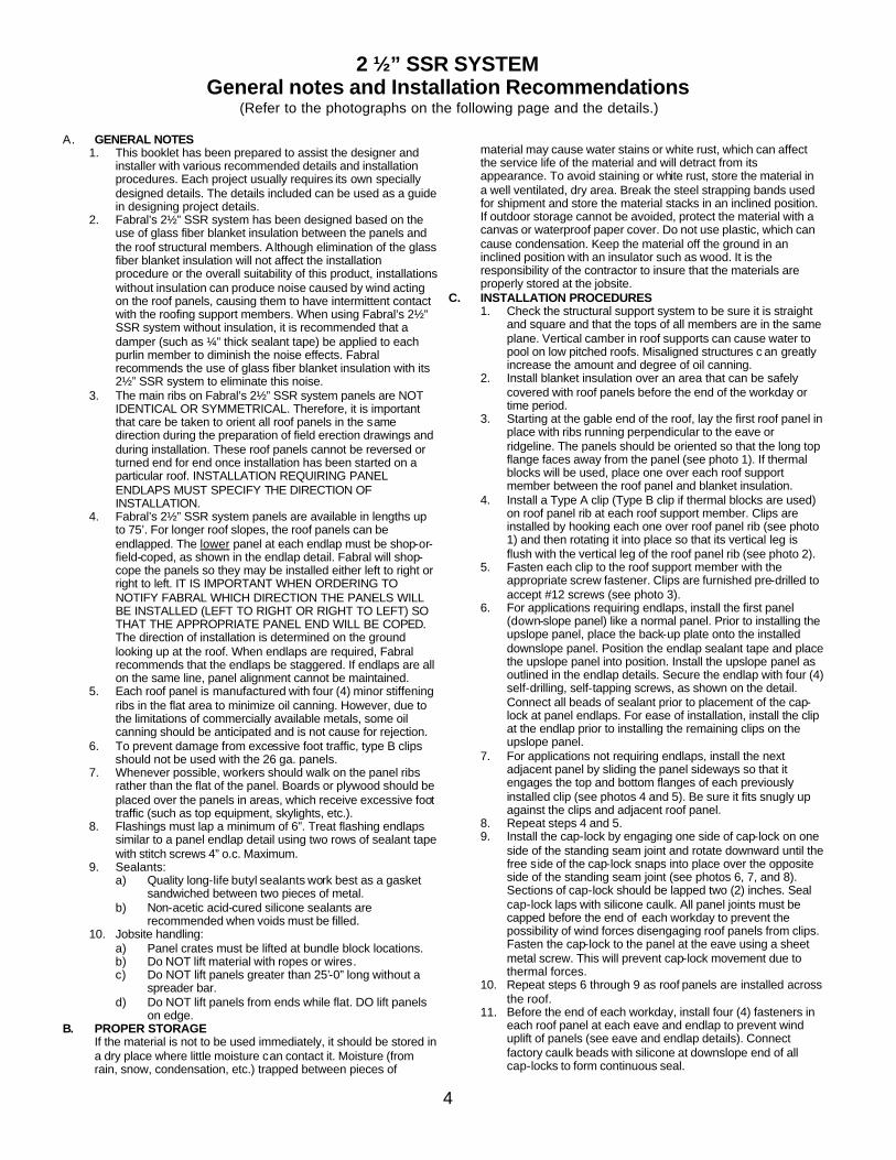
2 ½” SSR SYSTEMGeneral notes and Installation Recommendations
(Refer to the photographs on the following page and the details.)
A. GENERAL NOTES1. This booklet has been prepared to assist the designer and
installer with various recommended details and installation procedures. Each project usually requires its own specially designed details. The details included can be used as a guide in designing project details.
2. Fabral’s 2½” SSR system has been designed based on the use of glass fiber blanket insulation between the panels and the roof structural members. Although elimination of the glass fiber blanket insulation will not affect the installation procedure or the overall suitability of this product, installations without insulation can produce noise caused by wind acting on the roof panels, causing them to have intermittent contact with the roofing support members. When using Fabral’s 2½” SSR system without insulation, it is recommended that a damper (such as ¼” thick sealant tape) be applied to each purlin member to diminish the noise effects. Fabral recommends the use of glass fiber blanket insulation with its 2½” SSR system to eliminate this noise.
3. The main ribs on Fabral’s 2½” SSR system panels are NOT IDENTICAL OR SYMMETRICAL. Therefore, it is important that care be taken to orient all roof panels in the samedirection during the preparation of field erection drawings and during installation. These roof panels cannot be reversed or turned end for end once installation has been started on a particular roof. INSTALLATION REQUIRING PANEL ENDLAPS MUST SPECIFY THE DIRECTION OF INSTALLATION.
4. Fabral’s 2½” SSR system panels are available in lengths up to 75’. For longer roof slopes, the roof panels can be endlapped. The lower panel at each endlap must be shop-or-field-coped, as shown in the endlap detail. Fabral will shop-cope the panels so they may be installed either left to right or right to left. IT IS IMPORTANT WHEN ORDERING TO NOTIFY FABRAL WHICH DIRECTION THE PANELS WILL BE INSTALLED (LEFT TO RIGHT OR RIGHT TO LEFT) SO THAT THE APPROPRIATE PANEL END WILL BE COPED.The direction of installation is determined on the ground looking up at the roof. When endlaps are required, Fabral recommends that the endlaps be staggered. If endlaps are all on the same line, panel alignment cannot be maintained.
5. Each roof panel is manufactured with four (4) minor stiffening ribs in the flat area to minimize oil canning. However, due to the limitations of commercially available metals, some oil canning should be anticipated and is not cause for rejection.
6. To prevent damage from excessive foot traffic, type B clips should not be used with the 26 ga. panels.
7. Whenever possible, workers should walk on the panel ribs rather than the flat of the panel. Boards or plywood should be placed over the panels in areas, which receive excessive foottraffic (such as top equipment, skylights, etc.).
8. Flashings must lap a minimum of 6”. Treat flashing endlaps similar to a panel endlap detail using two rows of sealant tape with stitch screws 4” o.c. Maximum.
9. Sealants:a) Quality long-life butyl sealants work best as a gasket
sandwiched between two pieces of metal.b) Non-acetic acid-cured silicone sealants are
recommended when voids must be filled.10. Jobsite handling:
a) Panel crates must be lifted at bundle block locations.b) Do NOT lift material with ropes or wires.c) Do NOT lift panels greater than 25’-0” long without a
spreader bar.d) Do NOT lift panels from ends while flat. DO lift panels
on edge.B. PROPER STORAGE
If the material is not to be used immediately, it should be stored in a dry place where little moisture can contact it. Moisture (from rain, snow, condensation, etc.) trapped between pieces of
material may cause water stains or white rust, which can affect the service life of the material and will detract from its appearance. To avoid staining or white rust, store the material in a well ventilated, dry area. Break the steel strapping bands used for shipment and store the material stacks in an inclined position. If outdoor storage cannot be avoided, protect the material with a canvas or waterproof paper cover. Do not use plastic, which can cause condensation. Keep the material off the ground in an inclined position with an insulator such as wood. It is the responsibility of the contractor to insure that the materials are properly stored at the jobsite.
C. INSTALLATION PROCEDURES1. Check the structural support system to be sure it is straight
and square and that the tops of all members are in the same plane. Vertical camber in roof supports can cause water to pool on low pitched roofs. Misaligned structures c an greatly increase the amount and degree of oil canning.
2. Install blanket insulation over an area that can be safely covered with roof panels before the end of the workday or time period.
3. Starting at the gable end of the roof, lay the first roof panel in place with ribs running perpendicular to the eave or ridgeline. The panels should be oriented so that the long top flange faces away from the panel (see photo 1). If thermal blocks will be used, place one over each roof support member between the roof panel and blanket insulation.
4. Install a Type A clip (Type B clip if thermal blocks are used) on roof panel rib at each roof support member. Clips are installed by hooking each one over roof panel rib (see photo 1) and then rotating it into place so that its vertical leg is flush with the vertical leg of the roof panel rib (see photo 2).
5. Fasten each clip to the roof support member with the appropriate screw fastener. Clips are furnished pre-drilled to accept #12 screws (see photo 3).
6. For applications requiring endlaps, install the first panel (down-slope panel) like a normal panel. Prior to installing the upslope panel, place the back-up plate onto the installed downslope panel. Position the endlap sealant tape and place the upslope panel into position. Install the upslope panel as outlined in the endlap details. Secure the endlap with four (4) self-drilling, self-tapping screws, as shown on the detail. Connect all beads of sealant prior to placement of the cap-lock at panel endlaps. For ease of installation, install the clip at the endlap prior to installing the remaining clips on the upslope panel.
7. For applications not requiring endlaps, install the next adjacent panel by sliding the panel sideways so that it engages the top and bottom flanges of each previously installed clip (see photos 4 and 5). Be sure it fits snugly up against the clips and adjacent roof panel.
8. Repeat steps 4 and 5.9. Install the cap-lock by engaging one side of cap-lock on one
side of the standing seam joint and rotate downward until the free side of the cap-lock snaps into place over the opposite side of the standing seam joint (see photos 6, 7, and 8). Sections of cap-lock should be lapped two (2) inches. Seal cap-lock laps with silicone caulk. All panel joints must be capped before the end of each workday to prevent the possibility of wind forces disengaging roof panels from clips. Fasten the cap-lock to the panel at the eave using a sheet metal screw. This will prevent cap-lock movement due to thermal forces.
10. Repeat steps 6 through 9 as roof panels are installed across the roof.
11. Before the end of each workday, install four (4) fasteners in each roof panel at each eave and endlap to prevent wind uplift of panels (see eave and endlap details). Connect factory caulk beads with silicone at downslope end of all cap-locks to form continuous seal.

6
2 ½” SSR SYSTEM SPECIFICATION1.01 SUMMARY
A. Section includes: all material, labor, and equipment to complete installation of 2 ½” SSR roofing as shown on the drawing s and herein specified. Include all copings, gutters, and flashings contiguous with the panels.
B. Related Sections:1. Metal decking2. Rough carpentry, plywood, and underlayment3. Insulation4. Membrane roofing5. Flashing and sheet metal6. Joint sealers: sealants and caulk7. Structural framing.
1.02 REFERENCESA. American Society for Testing and Materials (ASTM)
1. ASTM A 653: Steel Sheet, Zinc-Coated by the Hot Dip Process.2. ASTM A 792: Steel Sheet, Aluminum-Zinc Alloy Coated by the Hot Dip Process.3. ASTM B 209: Aluminum and Aluminum Alloy Sheet and Plate.
B. Underwriters Laboratories1. UL580 wind uplift test (Class 90).
C. Sheet Metal and Air Condition Contractors National Associates, Inc. (SMACNA)1. SMACNA Architectural Sheet Metal Manual, 1993 Edition.
D. American Iron and Steel Institute (AISI)1. AISI Cold Formed Steel Design Manual
E. Aluminum Association1. Aluminum Design Manual
F. Metal Construction Association (MCA)1. Preformed Metal Wall Guidelines
G. Code References1. ASCE, Minimum Loads for Buildings and Other Structures2. BOCA National Building Code3. UBC Uniform Building Code4. SBC Standard Building Code
1.03 SYSTEM DESCRIPITIONA. Performance Requirements: Provide factory formed, prefinished, snap-together, concealed clip, structural
standing seam metal roof system, that has been pretested and certified by manufacturer to comply with specified requirements under installed conditions.1. The metal roofing system including required trim members shall meet the specified requirements for
snow loads, wind loads, air infiltration, and water penetration.2. The panels shall have a 2 ½” high finished joint, 18” o.c. including a factory-caulked, snap-on cap.
Mechanical crimpin g or sealing of the standing seam joint or cap is prohibited.3. The anchorage system shall be concealed. The panels’ clips shall permit the panel unlimited thermal
movement.4. Roof panels shall be a maximum possible length to minimize endlaps but shall be limited to 45’.5. Exposed fasteners are not permitted except at eaves, gabbles, valleys, and roof panel endlaps.6. The 2½”SSR panel system shall carry a UL Wind Uplift Class 90 rating to insure structural integrity and
possible reduction in insurance rates.7. The 2½”SSR panels shall have no air infiltration when tested in accordance with ASTM E 1680 with an
air pressure difference of 6.24 psf and 0.02 cfm/ft.2 leakage at 6.24 psf, 0.04 cfm/ft.2 leakage at 12.0 psf, and 0.08 cfm/ft.2 leakage at 20.0 psf.
8. The 2½”SSR panels shall have no air exfiltration when tested in accordance with ASTM E 1680 with an air pressure difference of 4.0 psf and 0.02 cfm/ft.2 leakage at 6.24 psf, 0.04 cfm/ft. 2 leakage at 12.0 psf, and 0.08 cfm/ft.2 leakage at 20.0 psf.
9. The 2½”SSR panels sha ll have no water leakage when tested in accordance with ASTM E 1646 with 20.0 psf pressure differential and 5 gal. /hr. spray.
B. Structural Requirements: Engineer panels for structural properties in accordance with latest edition of American Iron and Steel Institute’s Cold Formed Steel Design Manual using “effective width” concept and Aluminum Association’s Aluminum Design Manual.
1.04 SUBMITTALSA. Product Data: submit manufacturer’s specifications, standard profile sheet, product data brochure and finish
warranty.B. Shop Drawings: shop drawings showing roof plan with layout of panels, screws, underlayment and sections of
each flashing/trim condition shall be submitted for approval prior to fabrication. Drawings shall contain material type, metal thickness and finish. Drawings shall distinguish between factory and field fabrication.
C. Samples:1. Submit sample 12” long x full width panel, showing proposed metal gauge, seam profile and specified
finish.2. Submit manufacturers standard colors for Architect’s section.
D. Certification: Submit manufacturer’s certification that materials and finishes meet specification requirements.1.05 QUALITY ASSURANCE
A. Panel manufacturer shall have a minimum of ten (10) years of experience in manufacturing architectural roofing in a permanent stationary indoor facility.
B. Panel installer shall have a minimum of 5 years experience in installation of metal roofing of similar size and scope.
1.06 DELIVERY, STORAGE, and HANDINGA. Panels and flashings shall be protected and property packaged to protect against transportation damage in
transit to the jobsite.B. Upon delivery, exercise care in unloading, stacking, moving, storing, and erecting panels and flashings to
prevent twisting, bending, scratching, or denting.C. Store panels and flashings in a safe, dry environment und er a waterproof covering to prevent water damage.
Allow for adequate ventilation to prevent condensation. Panels and flashings with strippable film shall not be stored in direct sunlight.
D. Upon installation immediately remove strippable film from panels and flashings. Protect panels and flashings from foot traffic and from all other trades.
1.07 PROJECT CONDITIONSA. Field dimensions shall be taken prior to fabrication to verify jobsite conditions.B. Minimum recommended pitch for this panel is ½:12.
1.08 WARRANTIESA. Panel manufacturer shall provide a twenty (20) year warranty on the paint finish covering chalking, cracking,
checking, chipping, blistering, peeling, flaking, and fading.B. Applicator shall furnish written warranty for two (2) year period from date of substantial completion of building
covering repairs required to maintain roof and flashings in watertight conditions.2.01 PRODUCT DESCRIPTION
A. 2 ½” SSR structural standing seam roof system as manufactured by Fabral, 3449 Hempland Road, Lancaster, PA 17601, ph.: 717- 397- 2741; fax 717-397-1040.
B. The 2½” SSR panel shall have coverage of 18”. Seams shall be 2½” tall.C. Panels shall be attached to the substrate with one- piece concealed clips that permit unlimited thermal
movement.D. The panels shall use snap-on batten caps that will be manufactured in 16’-0” lengths. Caps shall be roll-formed
to a width of 2¼” and a depth of 1 1/16”. The top surface shall be curved to provide a spring-back action when installed. Caps shall be furnished with two beads of factory-applied caulk on the interior side.
E. There shall be four small stiffening beads in the flat of the panel.F. Inside and outside closures will be supplied and used as recommended in Fabral’s details.
2.02 PRODUCT SUBSTITUTIONA. Requests to use alternate systems shall be submitted in writing to the project designer at least ten (10) days prior
to bid date. Requests shall demonstrate proposed substitution meets or exceeds specified performance requirements. Certified statements, samples and descriptive data shall be included in this submittal request.
B. Manufactures listed in this section are prequalified manufactures. Substitution if manufacturer’s products for those specified shall not be allowed at anytime during construction.
2.03 MATERIALS AND FINISHESA. Panel material
1. 26, 24, 22, 20, or 18 gauge, Grade 40 (40 ksi yield strength) structural steel with G90 (0.90 oz./ft.2) hot dipped galvanized coating, both conforming to ASTM A 653.
2. 26, 24, 22, 20, or 18 gauge, Grad e40 (40 ksi yield strength) structural steel with AZ50 (0.50 oz./ft.2)aluminum-zinc alloy coating, both conforming to ASTM A 792.
3. 0.032, 0.040, or 0.050”, 3004- H36 or equivalent (28 ksi yield strength) aluminum alloy conforming to ASTM B 209.
B. Cap materials1. 26 or 24 gauge, Grade 40 (4 ksi yield strength) structural steel with G90 (0.90 oz./ft.2) hot dipped
galvanized coating, both conforming to ASTM A 653 (used with panels made of thicker metal).2. 26 or 24 gauge, Grade 40 (40 ksi yield strength) structural steel with AZ50 (0.50 oz./ft.2) aluminum-zinc
alloy coating, both conforming to ASTM A 792 (used with panels of thicker metal).
3. 0.032, 3004-H36 or equivalent (28 ksi yield strength) aluminum alloy conforming to ASTM B 209 (used with panels made of thicker metal).
C. Texture: panels shall be smooth.D. Finish: refer to manufacturer’s standard color card to determine appropriate finish and color. All panels shall
receive a factory-applied (siliconized polyester) (Kynar® 500/Hylar 5000®) (vinyl plastisol) conforming to the following:1. Metal preparation: all metal shall have the surfaces carefully prepared for painting on a continuous
process coil coating line by alkali cleaning, hot water rinsing, application of chemical conversion coating, cold water rinsing, sealing with an acid rinse, and thorough drying.
2. Prime coating: a base coat of epoxy paint, specifically formulated to interact with the top-coat, shall be applied to the prepared surfaces by roll coating to a dry film thickness of 0.20 ± 1.05 mils. This prime coat shall be oven cured prior to application of finish coat.
3. Exterior coating: a finish coating (see above) shall be applied over the primer by roll coating to a dry film thickness of 0.80 ± 0.05 mils (3.80 ± 0.05 mils for vinyl plastisol) for a total dry film thickness of 1.00 ±0.10 mils ( 4.00 ± 0.10 mils for vinyl plastisol). This finish coating shall be oven-cured.
4. Interior coating: a washcoat shall be applied on the reverse side over the primer by roll coating to a dry film thickness of 0.30 ± 0.50 mils for a total dry film thickness of 0.50 ± 0.10 mils. The washcoat shall be oven-cured.
5. Color: the color of the exterior finish shall be _____ as chosen from the manufacturer’s standard color chart.
6. Physical properties: the coating shall conform to the manufacturer’s standard performance criteria as listed by certified test reports for fade, chalk, abrasion, humidity, adhesion, pollution resistance, and others as required and standard within the industry.
2.04 ACCESSORIESA. Screws
1. All exposed fasteners shall have combination metal and neoprene washers. For prepainted roof panels, all exposed fasteners shall be prepainted to match the roof panel.
2. All fasteners shall be concealed except as shown on the drawing.3. Fasteners for the following locations shall be:
a. Clips to purlins: zinc plated(#12- 14 x 1½” self -drilling, self -tapping screws) (#14 HHB x 1” self -tapping screws).
b. Roof panels to eave support: (zinc-plated) (305 stainless steel) (#12- 14 x 1½” or 2½” self -drilling, self -tapping screws) (#14 HHB x 1” or 2” self -tapping screws).
c. Roof panel endlaps: (zinc-plated) (305 stainless steel) #14 x 1¼” self -drilling, self -tappingscrews.
d. Subgirts to roof panel ribs and flashings to subgirts: zinc plated (#12-14 x 1” self -drilling, self -tapping screws) (#14 HHA x ¾” sheet metal screws).
e. Flashings to roof panel ribs: (zinc plated) (305 stainless steel) (zinc- aluminum alloy plated) (#14 HHA x ¾” sheet metal screws) (#14 millpoint x 1” self -drilling stitch screws).
f. Screws fro flashings and sidelaps shall be #14 HHA x ¾” sheet metal stitch screws. All accessories, flashings, and sidelaps shall be fastened 12” o.c.
B. Back-up plates shall be die-punched from 18 gauge zinc- aluminum alloy coated steel and used to stiffen the panels at endlaps. The plates shall have two guide lances to align and hold the panels during installation.
C. Clips shall be die punched and shal l have both a purlin bearing flange and two (2) roof panel support flanges. The purlin bearing flange shall be prepunched for two (2) #12-14 self -drilling, self -tapping screws. Clips shall provide (¼”) (1 ¼”) clearance between the purlin bearing flange and the roof panel support flanges. Clip Material shall be 18 gauge zinc-aluminum alloy coated steel.
D. Insulation shall be glass-fiber blanket with a density of (0.6) (0.75) pcf and maximum thickness of 4”. The insulation shall be faced on one side only with an approved vapor barrier hacing sealing tabs. Insulation shall be supplied in rolls of sufficient length to permit a taut application from ridge to eave. When installed, the assembled system shall provide a maximum “U” value of 0.09 with 4” of insulation and a “U” value of 0.08 with 4” of insulation and 1” thermal blocks.
E. Thermal blocks shall be 1” thick by at least 3” wide by 17 1 5/16” long Styrofoam or approved equal applied over the blanket insulation at each purlin under each roof panel.
F. Closures1. Polyethylene closures shall be pre-molded to match the assembled panel system and in lengths as
supplied by the panel manufacturer.2. Metal closures shall be 26 or 24 gauge (G90 galvanized steel per ASTM A 653) (AZ50 zinc- aluminum
alloy coated steel per ASTM A 792) or 0.032” (thick aluminum alloy 3004 or equivalent per ASTM B 209) to match the assembled panel system and in lengths as supplied by the panel manufacturer.
G. Flashings shall be shop fabricated by the panel manufacturer from material that is the same thickness and finish as the panels to which they are attached. Where practical, flashings shall be furnished in maximum 10’ lengths. Exposed flashings shall be lapped 6”.
H. Subgirts shall be used under all flashings that span from rib to rib of the 2½”SSR panels. Subgirts shall be rollformed from 18 ga. G90 galvanized steel and shall be hat -shaped sections 3/8” deep x 3” wide with ¾” wide flanges. Subgirts shall be furnished in 20’ lengths.
I. Sealant tape used at roof panel endlaps shall be a butyl type roll as supp lied by the manufacturer.J. Caulking shall be a polyurethane where it is exposed and there is no thermal movement. All caulking or sealing
shall be done in a neat manner with excess caulking or sealant removed from exposed surfaces.K. Caulking shall be non-skinnig, non- hardening gun grade butyl sealant or butyl sealant tape with a minimum
thickness of 1/8” where it is concealed and where thermal movement must be accommodated. All caulking or sealing shall be done in a neat manner with excess caulking or sealant removed from exposed surfaces.
L. Flashings shall be shop-fabricated from material that is the same thickness and finish as the 2½”SSR panels to which they are attached. Where practicable, flashings shall be furnished in maximum 10’ lengths. Exposed flashings shall be lapped 6”
2.05 RELATED MATERIALSA. Refer to other sections listed in Related Sections paragraph for related materials.
2.06 FABRICATIONA. Endlaps will be allowed though swaging is required. Contact factory for details.B. Panels shall be roll formed on a station ary industrial type rolling mill to gradually shape the sheet metal. Portable
rollformers, rented or owned by the installer, are not acceptable.C. Fabricate flashings from the same material as the roof system.
2.07 SOURCE QUALITYA. Source quality: obtain metal panels and accessories from a single manufacturer.B. Fabrication tolerances:
1. Rib height: 2 ½” ± 1/8”.2. Panel shearing length: ± ¼” maximum3. Follow tolerances in MCA’s Preformed Metal Wall Guidelines.
C. Tests and inspectionsD. Verification of performance
3.01 MANUFACTURER’S INSTRUCTIONSA. Compliance: Comply with manufacturer’s product data, including product technical bulletins, product catalog
installation instructions, and product cartons for installation.3.02 EXAMINATION
A. Installer shall:1. Inspect purlins or deck to verify that it complies with shop drawing and is smooth, even, sound, and free
of depressions.2. Report variations and potential problems in writing to the architect.
3.03 INSTALLATIONA. Confom, to standard set forth in the SMACNA architectural sheet metal manuals and the appr oved shop
drawings detailed for the project.B. Install panels plumb, level, and straight with the seams parallel, conforming to the design as indicated.C. Install panel system so it is watertight, without waves, warps, buckles or distortions, and allow for thermal
movement considerations.D. Abrasive devices shall not be used to cut on or near roof panels system.E. Apply sealant tape at necessary at flashing and panel joints to prevent water penetration.F. Remove any strippable film immediately upon installation.G. Vapor Retarder: The joints, perimeter, and all openings shall be sealed per the manufacturer’s instructions to
provide a continuous vapor retarder.H. Underlayment (solid substrate):
1. Provide one layer of 30# felt with horizontal overlaps and endlaps staggered bet ween layers.2. Provide ice and water shield membrane at all valley and eave conditions as well as any area at less
than a 3:12 slope.3.04 CLEANING
A. Dispose of excessive materials and debris from jobsite.B. Remove filings, grease, stains, marks, or excess sealants from roof panel system to prevent staining.C. Protect work from damage from other trades until final acceptance.
Kynar® 500 is a registered trademark of Elf Atochem North America, Inc.Hylar® 5000 is a registered trademark of Ausimont USA, Inc.
7
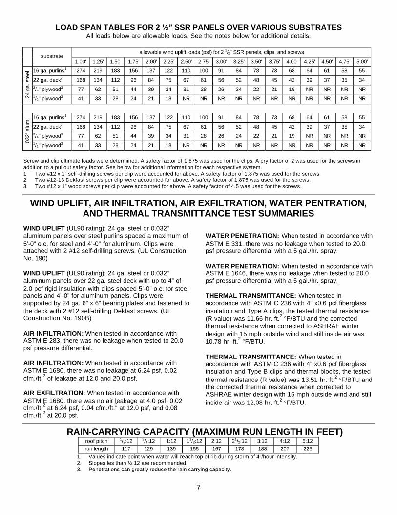
LOAD SPAN TABLES FOR 2 ½” SSR PANELS OVER VARIOUS SUBSTRATESAll loads below are allowable loads. See the notes below for additional details.
allowable wind uplift loads (psf) for 2 1/2" SSR panels, clips, and screwssubstrate
1.00' 1.25' 1.50' 1.75' 2.00' 2.25' 2.50' 2.75' 3.00' 3.25' 3.50' 3.75' 4.00' 4.25' 4.50' 4.75' 5.00'
16 ga. purlins1 274 219 183 156 137 122 110 100 91 84 78 73 68 64 61 58 55
22 ga. deck2 168 134 112 96 84 75 67 61 56 52 48 45 42 39 37 35 343/4" plywood3 77 62 51 44 39 34 31 28 26 24 22 21 19 NR NR NR NR
24 g
a. s
teel
1/2" plywood3 41 33 28 24 21 18 NR NR NR NR NR NR NR NR NR NR NR
16 ga. purlins1 274 219 183 156 137 122 110 100 91 84 78 73 68 64 61 58 55
22 ga. deck2 168 134 112 96 84 75 67 61 56 52 48 45 42 39 37 35 343/4" plywood3 77 62 51 44 39 34 31 28 26 24 22 21 19 NR NR NR NR
.032
" alu
m.
1/2" plywood3 41 33 28 24 21 18 NR NR NR NR NR NR NR NR NR NR NR
Screw and clip ultimate loads were determined. A safety factor of 1.875 was used for the clips. A pry factor of 2 was used for the screws in addition to a pullout safety factor. See below for additional information for each respective system. 1. Two #12 x 1” self -drilling screws per clip were accounted for above. A safety factor of 1.875 was used for the screws.2. Two #12-13 Dekfast screws per clip were accounted for above. A safety factor of 1.875 was used for the screws.3. Two #12 x 1” wood screws per clip were accounted for above. A safety factor of 4.5 was used for the screws.
WIND UPLIFT, AIR INFILTRATION, AIR EXFILTRATION, WATER PENTRATION, AND THERMAL TRANSMITTANCE TEST SUMMARIES
WIND UPLIFT (UL90 rating): 24 ga. steel or 0.032” aluminum panels over steel purlins spaced a maximum of 5’-0” o.c. for steel and 4’-0” for aluminum. Clips were attached with 2 #12 self-drilling screws. (UL Construction No. 190)
WIND UPLIFT (UL90 rating): 24 ga. steel or 0.032” aluminum panels over 22 ga. steel deck with up to 4” of 2.0 pcf rigid insulation with clips spaced 5’-0” o.c. for steelpanels and 4’-0” for aluminum panels. Clips were supported by 24 ga. 6” x 6” bearing plates and fastened to the deck with 2 #12 self-drilling Dekfast screws. (UL Construction No. 190B)
AIR INFILTRATION: When tested in accordance with ASTM E 283, there was no leakage when tested to 20.0 psf pressure differential.
AIR INFILTRATION: When tested in accordance with ASTM E 1680, there was no leakage at 6.24 psf, 0.02 cfm./ft.2 of leakage at 12.0 and 20.0 psf.
AIR EXFILTRATION: When tested in accordance withASTM E 1680, there was no air leakage at 4.0 psf, 0.02 cfm./ft.2 at 6.24 psf, 0.04 cfm./ft.2 at 12.0 psf, and 0.08 cfm./ft.2 at 20.0 psf.
WATER PENETRATION: When tested in accordance with ASTM E 331, there was no leakage when tested to 20.0 psf pressure differential with a 5 gal./hr. spray.
WATER PENETRATION: When tested in accordance with ASTM E 1646, there was no leakage when tested to 20.0 psf pressure differential with a 5 gal./hr. spray.
THERMAL TRANSMITTANCE: When tested in accordance with ASTM C 236 with 4” x0.6 pcf fiberglass insulation and Type A clips, the tested thermal resistance (R value) was 11.66 hr. ft.2 °F/BTU and the corrected thermal resistance when corrected to ASHRAE winter design with 15 mph outside wind and still inside air was 10.78 hr. ft.2 °F/BTU.
THERMAL TRANSMITTANCE: When tested in accordance with ASTM C 236 with 4” x0.6 pcf fiberglass insulation and Type B clips and thermal blocks, the tested thermal resistance (R value) was 13.51 hr. ft.2 °F/BTU and the corrected thermal resistance when corrected to ASHRAE winter design with 15 mph outside wind and still inside air was 12.08 hr. ft.2 °F/BTU.
RAIN-CARRYING CAPACITY (MAXIMUM RUN LENGTH IN FEET)roof pitch 1/2:12 3/4:12 1:12 11/2:12 2:12 21/2:12 3:12 4:12 5:12run length 117 129 139 155 167 178 188 207 225
1. Values indicate point when water will reach top of rib during storm of 4”/hour intensity.2. Slopes les than ½:12 are recommended.3. Penetrations can greatly reduce the rain carrying capacity.

8
THERMAL MOVEMENT TABLEPanel movement with a 100°F temperature change in the panel, and a 50°F temperature change in the substrate.
PANEL LENGTH (FT.)PANEL AND SUBSTRATE MATERIALS10' 50' 100'
steel on rigid insulation 3/32" 13/32" 25/32"steel on wood 1/16" 3/8" 5/8"steel on steel 1/16" 3/8" 13/32"steel on concrete 1/16" 3/8" 15/32"aluminum on rigid insulation 5/32" 25/32" 1 9/16"aluminum on wood 5/32" 11/16" 1 3/8"aluminum on steel 1/8" 19/32" 1 5/32"aluminum on concrete 1/8" 5/8" 1 7/32"
FASTENER USAGE TABLEsubstrate clip screw panel material exposed screw
galvanized steel #12-14 zinc -plated SDSTaluminum #14 stainless steel HHAcold-formed steel #12 zinc-plated SDSTzinc-aluminum coated steel #12-14 SDST ZAC-headgalvanized steel #14 zinc-plated HHBaluminum #14 stainless steel HHBhot-rolled steel #14 zinc-plated HHBzinc-aluminum coated steel #14 stainless steel HHBgalvanized steel #14 zinc plated mill pointaluminum #14 stainless steel HHAsteel deck #12-13 Dekfastzinc-aluminum coated steel #14 ZAC-head mill pointgalvanized steel #14 zinc plated mill pointaluminum #14 stainless steel HHAsolid wood #12 zinc-plated A -pointzinc-aluminum coated steel #14 ZAC-head mill pointgalvanized steel #14 zinc plated mill pointaluminum #14 stainless steel HHAplywood #12 zinc-plated A -pointzinc-aluminum coated steel #14 ZAC-head mill point
PROFILE AVAILABILITY TABLECOMPONENT MATERIAL THICKNESS WT./SQ. PLAIN WT./SQ. PAINTED
0.032" 63.6 lb. 65.2 lb.0.040" 79.5 lb. 80.9 lb.aluminum0.050"a 99.3 lb. 100.7 lb.26 ga. 127.0 lb. 128.6 lb.24 ga. 162.0 lb. 163.3 lb.22 ga. 197.0 lb. 198.6 lb.20 ga. 232.0 lb. 233.8 lb.
galvanized steel
18 ga.a 302.0 lb. 303.9 lb.26 ga. 122.1 lb. 124.0 lb.24 ga. 156.7 lb. 158.5 lb.22 ga. 191.8 lb. 193.7 lb.20 ga. 227.0 lb. 228.8 lb.
panel
aluminum-zincalloy coated steel
18 ga.a 297.2 lb. 299.1 lb.aluminum 0.032"b 10.0 lb. 10.4 lb.
26 ga. 20.0 lb. 20.3 lb.galvanized steel
24 ga.c 25.5 lb. 25.8 lb.26 ga. 19.2 lb. 19.5 lb.
cap-lock(weights are for four pieces, 16'-10" long each)d aluminum-zinc
alloy coated steel 24 ga.c 24.7 lb. 25.0 lb.a. 18 ga. steel and 0.050” aluminum panels cannot be endlapped.c. Cap-lock used for 24 ga. and thicker steel.
b. Use this cap-lock for all aluminum panels.d. Quantity of cap-lock reqired per square of panel.

9
BEARING PLATE (6" x 6" x 24 GA.)
FIBERGLASS INSULATION (4"MAX. THICKNESS FOR ALUM-INUM PANELS, 6" MAX. THICK-NESS FOR STEEL PANELS)
FIBERGLASS INSULATION (4"MAX. THICKNESS FOR ALUM-INUM PANELS, 6" MAX. THICK-NESS FOR STEEL PANELS)
INSTALLATION OVER STEEL PURLINS (WITH THERMAL BLOCKS)
INSTALLATION OVER STEEL PURLINS (WITHOUT THERMAL BLOCKS)
SELF-DRILLING SCREWS
CLIP (TYPE B)THERMAL BLOCK
RIGID INSULATION (6" MAX.)STEEL DECK (22 GA. MIN.)
#12-13 DEKFAST SCREW
INSTALLATION OVER STEEL DECK
INSTALLATION OVER PLYWOOD DECK30# FELT
SELF-TAPPING SCREWSCLIP (TYPE A) 2 1/2" SSR PANEL
PLYWOOD DECK
PURLIN
CLIP (TYPE A) 2 1/2" SSR PANEL
ATTACHMENT DETAILS
PURLIN
SELF-DRILLING SCREWS
CLIP (TYPE A)
2 1/2" SSR PANEL
2 1/2" SSR PANEL

PEAK DETAIL
PURLIN
PEAK FLASHING
HIP DETAIL
PURLIN
2"MIN.
RIDGE DETAIL
12" TYPICAL
2"MIN.
PURLIN
CLIP SCREW
CLIPCAP-LOCK
SUBGIRT
SCREW (4/PANEL)
METAL CLOSURE (CAULK PERIMETER)
RIDGE FLASHING
POLY. CLOSURE (CAULK PERIMETER)
SILICONE SEALANT TOCONNECT ALL SEALANTS
CLIP SCREW
CLIPCAP LOCK
SUBGIRT
FIELD-NOTCHED METALZ (CAULK PERIMETER)
SCREW (4/PANEL; DO NOTPENETRATE SUBSTATE)
SCREW (4/PANEL)HIP FLASHING
BEVELED POLY. CLOSURE(CAULK PERIMETER)
SILICONE SEALANT(CONNECT ALL SEALANTS)
SCREW (4/PANEL)METAL CLOSURE (CAULK PERIMETER)
SUBGIRT
SILICONE SEALANT (CONNECT ALL SEALANTS)CAP-LOCK
CLIP SCREWCLIP
POLY. CLOSURE(CAULK PERIMETER)
10

EAVE WITH GUTTER DETAIL
VALLEY DETAIL
2"
EAVE WITHOUT GUTTER DETAIL
END CAP (SET IN SEALANT)
6" MIN.
PURLIN
EAVE STRUTEAVE FLASHING
SCREW (4/PANEL)SILICONE SEALANT BETWEEN WEBS;
CONNECT TO OTHER SEALANTSSCREW THROUGH END CAP,
CAP-LOCK, AND PANEL
2 1/2" SSR PANELCAP-LOCK
2 1/2" SSR PANELCAP-LOCK
SCREW (4/PANEL)SILICONE SEALANT BETWEEN WEBS;
CONNECT TO OTHER SEALANTSSCREW THROUGH END CAP,
CAP-LOCK, AND PANEL
EAVE STRUT
END CAP (SET IN SEALANT)
1"
1"
END CAP (SEAL AND FASTEN)
VALLEY SUPPORTICE & WATER SHIELD
VALLEY FLASHING
SEALANT TAPE
SILICONE SEALANT BETWEENWEBS; CONNECT TO OTHER
SEALANTS
SCREW (4" O.C.)
11

CLIP NOT SHOWN FOR CLARITY
ENDLAP DETAIL
2 3/4"
1"
1 1/2"
PURLIN
SELF-TAPPINGSCREW (4/PANEL)
TRANSITION DETAIL
END CAP (SEAL AND FASTEN)
TRANSITION FLASHING
RIGID INSULATIONFOR FLASHING SUPPORT(CUT AS NEEDED)
METAL CLOSURE(CAULK PERIMETER)
POLY. CLOSURE(CAULK PERIMETER)CLIP
CLIP SCREW
CAP-LOCK
SILICONE SEALANT (CONNECTTO OTHER SEALANTS)
HEM (FILL W/ BUTYL SEALANT)SCREW (12" O.C.)
CONTINUOUS CLEATSUBGIRT
SCREW (4/PANEL)
SEALANT BETWEEN WEBS(CONNECT TO OTHER SEALANTS)
SCREW (4/PANEL)
CAP-LOCK
2 1/2" SSR PANEL
UPSLOPE PANEL
BACKUP PLATE
FACTORY COPE/FLARE
ENDLAP TAPE CAULK(CAULK PAN AND WEBS)
DOWNSLOPE PANEL
1/2"
8"
13

RADIUS CORNER
FLANGE
END VIEW
OUTSIDE BEND DETAILS
4. Even if the project is uninsulated, it is still necessary to place 4" thick insulation continuously over the eave and base structural members. Place the base flashing over the insulation to prevent water siphoning. Place the panel into position. Attach the panel to the girt with four screws per panel. Seal the ends of the webs at the base with caulk.
3. Set the panel on a firm, flat, working surface. Apply downward pressure at the bend line. Bend the panel beyond the desired angle. Then, return the panel bend to the desired angle to set the crease.
1. Measure and mark the distance from the end of the panel to the bend point.
2. Cut the panel flanges and webs to the radius corner. It may be necessary to make V-notches at the flanges to cut the webs.
CONTINUOUS2 1/2" SSR PANEL
BASE FLASHING
SCREW (4/PANEL)
WORKING SURFACE
CUT LINE
PANEL PAN (DO NOT CUT)
SIDE VIEW
CUT LINE
WEB
9. Apply the cap-lock to the panel starting at the base and working toward the ridge.
10. Seal all cuts with clear caulk.
FILLER PLATE
CONTINUOUS2 1/2" SSR PANEL
END VIEWSIDE VIEW
V-NOTCH
SEALANT
SIDE VIEW
45
8. Place the cap-lock on a firm, flat, working surface. Bend the cap to the desired angle.
7. Measure and mark the distance from end of the cap-lock to the desired bend point. V-notch the cap-lock webs at 45∞ angles to the top bend line.
CUT UP TOTHIS POINT
WORKING SURFACE
END VIEW
2 1/2" SSR PANEL
FILLER PLATE
END VIEW
CUT WEB ONLY
5. Cut two filler plates to a length of 15". Cut the filler plates' webs at their midpoints. Bend the filler plates to the desired angle with the webs of the upslope portion inside the webs of the downslope portion. Apply the filler plates between adjacent panels' webs. Caulk between the filler plates and panel webs. Apply caulk to the top of the filler plates' flanges.
15"
2 5/8"
3/4"
14

WORKING SURFACE
WORKING SURFACE
FIRM WORKING SURFACE
RADIUS CORNER
FLANGE
COPE OUTTOP FLANGES
4. Place the panel on a firm, flat working surface. Clamp a rigid member at the bend line. Bend the panel 90∞ to set the crease with the upslope panel webs inside the downslope panel webs. Then, bend the panel to the desired angle.
1. Mark the distance from the end of the panel to the desired bend line.
2. On each side of the panel, cut the flange and web to the radius corner of the pan.
3. On each side of the panel, remove the flanges for 3" on either side of the bend line for clearance when the panel is bent.
FLOW
OF W
ATER
BENDING TO DESIRED ANGLE
BENDING TO 90∞
CLAMPED MEMBER
WORKING SURFACE
8. Apply the cap-lock to the panel starting at the eave.
9. Seal all cuts at the bends with clear caulk.
CUT WEBS
SCREW (4/PANEL/PURLIN)
5. Place 4" insulation over the purlins at the pitch change, even if the rest of the roof is uninsulated. Attach the panel to the purlins with four screws per panel width per purlin.
7. Place the cap-lock on a firm, flat, working surface and bend it to the desired angle.
6. Measure and mark the distance from the end of the cap-lock to the desired bend point. Cut the cap-lock webs.
CLAMPED MEMBER
BEFORE BENDING
SIDE VIEW
END VIEW
WEB
CUT WEBS TOTHIS POINT
END VIEW SIDE VIEW
INSULATION
INSIDE BEND DETAILS
CUT WEBS3"3"
2 1/2" SSR PANEL(UPPER WEBS INSIDE
LOWER WEBS)
15

FASCIA OUTSIDE CORNER DETAIL
FASCIA INSIDE CORNER DETAIL
BASE DETAIL
2 1/2" SSR PANEL
SCREW (4/PANEL)
DRIP FLASHING
2 1/2" SSR PANELGIRT
SEALANT TAPESCREW (12" O.C.)
INSIDE CORNER FLASHING
CAULK BETWEEN WEBS
INSIDE CORNER FLASHING
GIRT
SEALANT TAPE
SCREW (12" O.C.)
2 1/2" SSR PANEL
16

CURB SUPPORT
FASTENER W/ WASHER; FASTEN 6" O.C.;DO NOT PENETRATE CURB SUPPORT
2 ROWS OF SEALANT TAPE
BEND UP PANEL 5" MIN.
CURB COVER TRIM
4"±
A
2 1/2" SSR PANEL
6" MIN.
CLOSURES AND SEALANTS(SEE RIDGE DETAIL)
PRE-FABRICATED CURB
SCREW (4/PANEL); DO NOT PENETRATE CURB SUPPORT
ENDCAP (CAULKAND FASTEN)
SEALANT BETWEENWEBS; CONNECT ALL
OTHER SEALANTS
CRICKET
1' MAX.1' MAX
2' MAX
1" MIN.
1" MIN.
CURB (FIXED)CURB (MOVING)
SECTION A-A
1" MIN.
1" MIN.
B
CAP-LOCKPRE-FABRICATED CURB (MOVING)INNER CURB (FIXED) ROOF PANEL
DOWNSLOPE
B
OPEN
A
SCREW (6" O.C.)
CURB (FIXED)CURB (MOVING)
18 GA. UPLIFT CLIP (ATTACH TO CURB ONLY)
1" MIN.
1" MIN.
SECTION B-B
CURB OVER PURLINS
CURB FLASHING; MUSTALLOW OUTER CURBTO MOVE WITH PANELS
PANCAKE HEAD SCREW
CURB FLASHING; MUST ALLOWOUTER CURB TO MOVE WITH PANELS
CURB SUPPORT
PURLIN
17

1" MIN.
1' MAX.
1" MIN.
B
OPEN
DOWNSLOPE
1" MIN.
CURB (FIXED)CURB (MOVING)
6" MIN.
4"±
1" MIN.
1' MAX
18 GA. UPLIFT CLIP (ATTACH TO CURB ONLY)
PAN HEAD FASTENER
CURB (MOVING)CURB (FIXED)
SCREW (6" O.C.)
SECTION B-B
2' MAX
1" MIN.
1" MIN.
SECTION A-A
1" MIN.
1" MIN.
B
ROOF PANELINNER CURB (FIXED)PRE-FABRICATED CURB (MOVING)
A A
CURB OVER DECK
CAP-LOCK
SCREW (4/PANEL)
SEALANT BETWEENWEBS; CONNECT ALL
OTHER SEALANTS
DECK
CRICKET
ENDCAP (CAULKAND FASTEN)
PRE-FABRICATED CURB
CLOSURES AND SEALANTS(SEE RIDGE DETAIL)
2 1/2" SSR PANEL
CURB FLASHING; MUST ALLOW OUTER CURB TO MOVE WITH PANELS
CURB COVER TRIM
BEND UP PANEL 5" MIN.
CURB SUPPORT FASTENER W/ WASHER; FASTEN 6" O.C.;DO NOT PENETRATE CURB SUPPORT
2 ROWS OF SEALANT TAPE
CURB FLASHING; MUSTALLOW OUTER CURB TOMOVE WITH PANELS
2 ROWS OF SEALANT TAPE
18

VENT PIPE
PIPE PENETRATION DETAILTHE HOLE IN PANEL (AND DECK, IF PRESENT) SHOULD BE CUT AT LEAST 2" LARGER IN DIAMETER THAN PIPE BOOT FLANGE.
ATTACH THE PIPE BOOT BASE TO PANEL WITH SCREWS 2" O.C. DO NOT PENETRATE ANY STRUCTURAL MEMBERS WITH THE SCREWS. SCREWS SHOULD BE AT SPACED AT LEAST 1" FROM STRUCTURAL MEMBERS.
PIPE PENETRATIONS SHOULD BE CENTERED IN THE WIDTH OF THE PANELS AS SHOWN.
SEALANT
PIPE BOOT
FASTENER
SOLID DECK (CUT HOLE AT LEAST 2" LARGERIN DIAMETER THAN PIPE BOOT FLANGE)
1. Prior to placement of curbs and panels, check to see that adequate structural support exists. Since the panels are supporting the weight of the curb and design loads and the purlins are supporting the additional weight of the equipment, the purlins must be designed and spaced so that these loads can be safely distributed to the main frame.
2. Place the curb at the desired location on the roof. Lap the panels over the upslope and downslope curb flanges by at least 8". Lap the panels over the side curb flanges by at least 4".
3. Location, placement, and design of curbs should be such that at least 6" of panel width exists between the curb side and web as shown in the drawings. This will prevent funneling water into a narrow path which may result in a flooded web and a potential leak source.
4. Install the lower curb over the supporting members and weld or fasten the curb with flat-head fasteners. A flat surface is required because the upper curb slides on the lower curb flange.
5. Downslope flanges should be field-notched to slide around the vertical webs.
6. Panel-to-curb fasteners must not penetrate or interfere with structurals below the curb.
NOTES FOR CURB DETAILS
19

Headquarters 3449 Hempland Road, Lancaster, PA 17601
Other Manufacturing Facilities Route 24 West, Gridley, IL 71744
308 Alabama Blvd., Jackson, GA 30233 Route 3, Box 632, Idabel, OK 74745
2402 Industry Way, Cedar City, UT 84720 4570 Ridge Drive, N.E., Salem, OR 97303
East 6207 Desmet Ave, Spokane, WA 99212 1820 East 26th St., Marshfield, WI 54449 55 Lamb Loop Road, Tifton, GA 31793
600 15th Ave N.E., St. Joseph, MN 56374 1820 East 26th Street, Marshfield, WI 54449
World Wide Web address: www.fabral.com e-mail address: [email protected]
© 2002 Fabral 98-32-146 10/2010