18sp680rev3 – epa04 mbe 4000 car hauler low pressure fuel
TRANSCRIPT
18SP680Rev3 Page 1 of 19
18SP680Rev3 – EPA04 MBE 4000 Car Hauler Low Pressure Fuel Lines KIT DESCRIPTION These service kits include all necessary parts to replace the low pressure fuel lines between the fuel filter housing and fuel pump/block on EPA04 MBE 4000 Car Hauler applications. Depending on the engine serial number, a fuel pump kit or fuel filter module will be replaced as well. The serial number ranges are below. Engine Serial Number range Parts needed
0460787244 – 0460846192 Low pressure fuel line kit (P/N: A4600703932) and fuel pump kit (P/N: A4600900150)
0460846193 – 0460877813 Low pressure fuel line kit (P/N: A4600703932) 0460878654 – 0460884179 Low pressure fuel line kit (P/N: A4600703932)
and fuel filter module parts (see Table 3)
Figure 1 Routing Overview

18SP680Rev3 Page 2 of 19
KIT CONTENTS Table 1 (Low Pressure Fuel Line Kit P/N: A4600703932) contains the following components:
Part Number Quantity Description A4600908376 1 Fuel Line (Block to Filter) A4600908476 1 Fuel Line (Pump to Filter) N000000001070 12 Seal Ring N915036012101 3 Banjo Bolt – M16 N915047012100 1 Banjo Bolt – M16 A0049902082 8 Spacer, 4.5mm N000000003175 6 Nut - M8 A0019954042 21 P – Clip N910105008011 5 Bolt – M8X20 N910143008003 6 Bolt – M8X30 23-09130-017 2 L-Bracket 23-13039-008 1 Straight Fitting UMP_S464G10 2 P-Clamp UMP_S464G20 2 P-Clamp 23-10742-075 3 1/4 – 20X3/4 23-13861-104 3 1/4 -20 Lock Nut 23-09796-509 10 Zip Ties TYC DCT110HIR 6 Double Zip Ties PH43706L108035 1 Long Drop Pressure Hose 90 A0089975172 3 Adapter A4600980080 1 Mixer housing gasket 18SP680Rev3 1 Installation Instructions Table 1 Low Pressure Fuel Line Kit, P/N: A4600703932 The fuel pumps can be visually identified by comparing length and line mounting location. See Figure 2. Table 2 (Fuel Pump Replacement Kit) contains the following components:
Part Number Quantity Description A4570910601 1 Fuel Pump A4570910180 1 Fuel Pump Mounting Gasket A4600903476 1 Fuel Return Line N916016016201 3 Fuel Line P - Clip Table 2 Fuel Pump Replacement Kit (if needed), P/N: A4600900150

18SP680Rev3 Page 3 of 19
Figure 2 Fuel Pump Visual Identification
Table 3 (Fuel Filter Module Replacement Parts) requires the following components:
Part Number Quantity Description A5410900852 1 Fuel Filter Module N000000001070 2 Seal Ring N007603008103 2 Seal Ring
Table 3 Optional Fuel Filter Module Replacement Parts (if needed) REPAIR PROCEDURE 1. Shut down the engine and apply the parking brake, chock the wheels, and perform any other applicable safety steps.
NOTICE: Be sure the rear hitch does not make contact with the work floor surface.
2. Put jack stands under front axle. 3. Open the hood. 4. Disconnect the main batteries at the negative terminals. 5. Remove the passenger seat if applicable. 6. Remove the engine cover from the inside of the truck. 7. Drain the fuel system by unscrewing the fuel filter module cap. 8. Remove the plastic oil breather hose. 9. Remove the left front tire. 10. Remove the left front splash shield and left front fender. 11. Remove the mounting screws on the fuse box; swing fuse box out towards the rear of the vehicle. Properly support the fuse box. 12. Remove the air filter housing and mounting bracket. 13. Loosen the charge air cooler hose clamp at the charge air cooler. 14. Remove the intake elbow and charge air cooler hose from the air system. 15. Remove the radiator support bar. 16. Disconnect the steering shaft from the power steering gearbox, position aside. 17. Remove the frame-mounted fuel water separator filter (if equipped); refer to OEM guidelines. 18. Release the belt tensioner pulley, and remove the main drive belt from the alternator pulley. See Figure 3.
New Pump
Old Pump
18SP680Rev3 Page 4 of 19
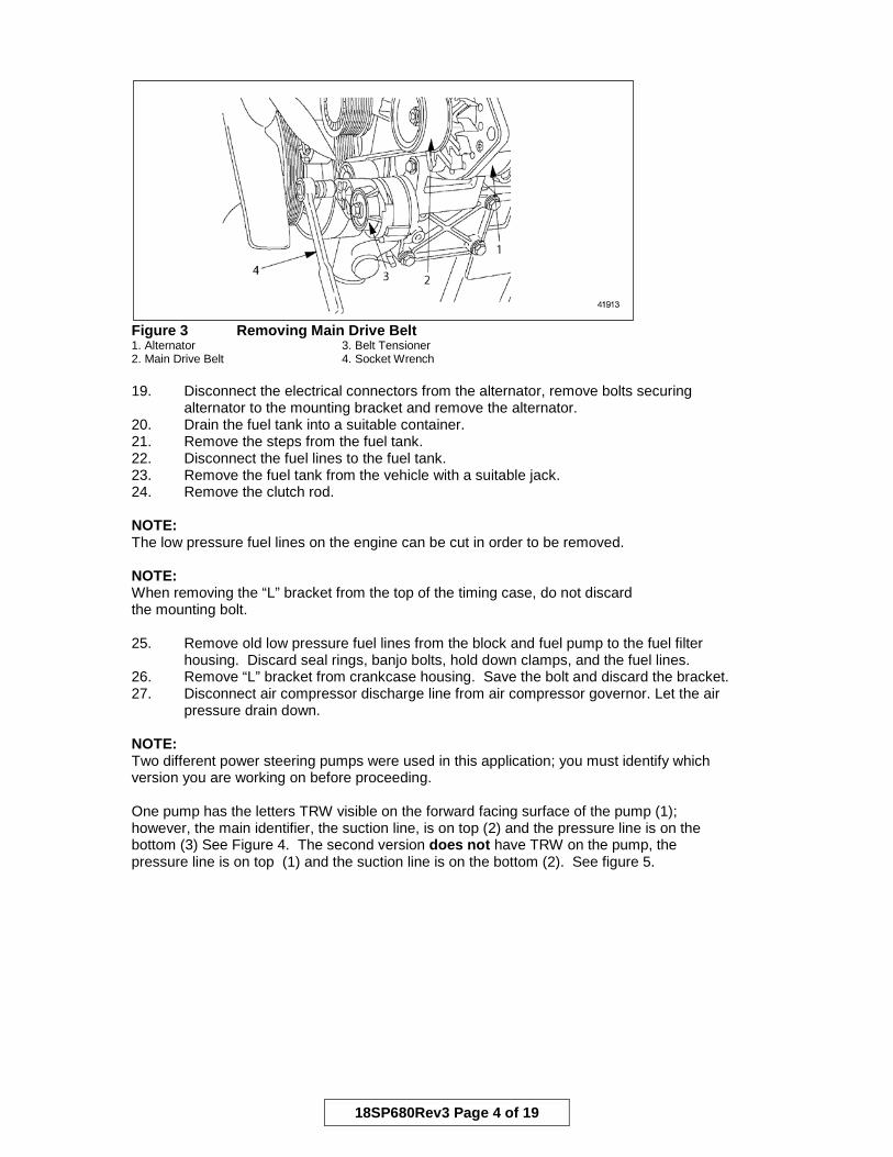
Figure 3 Removing Main Drive Belt 1. Alternator 3. Belt Tensioner 2. Main Drive Belt 4. Socket Wrench 19. Disconnect the electrical connectors from the alternator, remove bolts securing alternator to the mounting bracket and remove the alternator. 20. Drain the fuel tank into a suitable container. 21. Remove the steps from the fuel tank. 22. Disconnect the fuel lines to the fuel tank. 23. Remove the fuel tank from the vehicle with a suitable jack. 24. Remove the clutch rod. NOTE: The low pressure fuel lines on the engine can be cut in order to be removed. NOTE: When removing the “L” bracket from the top of the timing case, do not discard the mounting bolt. 25. Remove old low pressure fuel lines from the block and fuel pump to the fuel filter housing. Discard seal rings, banjo bolts, hold down clamps, and the fuel lines. 26. Remove “L” bracket from crankcase housing. Save the bolt and discard the bracket. 27. Disconnect air compressor discharge line from air compressor governor. Let the air pressure drain down. NOTE: Two different power steering pumps were used in this application; you must identify which version you are working on before proceeding. One pump has the letters TRW visible on the forward facing surface of the pump (1); however, the main identifier, the suction line, is on top (2) and the pressure line is on the bottom (3) See Figure 4. The second version does not have TRW on the pump, the pressure line is on top (1) and the suction line is on the bottom (2). See figure 5.

18SP680Rev3 Page 5 of 19
Figure 4 – Power Steering Pump with Suction Line on Top
Figure 5 – Power Steering Pump with Pressure Line on Top 28. Does the power steering pump have the pressure line on top?
a. Yes, go to the next step. b. No, go to step 37.
29. Drain the power steering fluid in to a suitable container. 30. Loosen the power steering pressure line from the power steering pump and power steering gear box. 31. Remove the power steering pressure line clips and power steering pressure line. Discard the power steering line. 32. Clean the power steering pump pressure line connection surface. 33. Remove the 90 degree adapter on the power steering pump. 34. Install new power steering pressure line adaptor part number 23-13039-008. Torque to 42-55 N·m (31-41 lb·ft). 35. Install power steering pressure line part number PH43706L108035 by attaching the 90 degree fitting to the power steering pump. Do not connect to gear box at this time.
1
2
3
1 2

18SP680Rev3 Page 6 of 19
36. Angle the power steering pressure line slightly outward toward the frame rail (1). Torque the power steering pressure line at the pump to 42-55 N·m (31-41 lb·ft). See Figure 6.
Figure 6 - Torque the Power Steering Pressure Line 37. Remove the fuel line bracket; discard the spacers and old fuel line clamps. See Figure 7.
Figure 7 Fuel Line Bracket 38. Does this engine fall within the engine serial number range to replace the fuel pump?
a. Yes; go to next step. b. No; go to step 50.
39. Remove the banjo bolts on the fuel return line from the PLD, fuel pump, and fuel pressure regulator. 40. Remove the P-clips holding the fuel line to the cylinder crankcase. 41. Remove the fuel return line. 42. Remove the fuel pump. 43. Clean the fuel pump mounting surface. 44. Apply a mild spray adhesive to the fuel pump gasket and place on fuel pump.
NOTICE: The spline on the fuel pump can be damaged due to improper mounting.
1
18SP680Rev3 Page 7 of 19
45. Install the new fuel pump on the engine with the weep hole in the 6 o’clock position. Torque the socket-head bolts on the fuel pump to 25 N·m (18 lb·ft). 46. Install the new fuel return line part number A4600903476 onto the cylinder crankcase. 47. Install new P-clips part number N916016016201 onto the fuel return line and tighten by hand. 48. Install the banjo bolts with seal rings on the PLD, fuel pump, and the fuel pressure regulator. Tighten by hand. 49. Torque banjo bolts to 35 N·m (26 lb·ft). 50. Torque P-clips on the fuel return line to 25 N·m (18 lb·ft). 51. Install the fuel line bracket with new shims part number A0049902082 between the bracket and the cylinder crankcase in the original location. 52. Torque fuel bracket bolts to 35 N·m (26 lb·ft). 53. Does this engine fall within the engine serial number range to replace the fuel filter module?
a. Yes; go to next step. b. No; go to step 58.
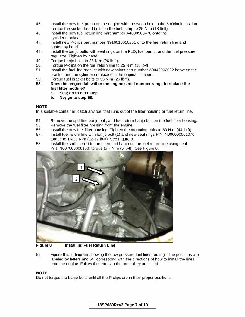
NOTE: In a suitable container, catch any fuel that runs out of the filter housing or fuel return line. 54. Remove the spill line banjo bolt, and fuel return banjo bolt on the fuel filter housing. 55. Remove the fuel filter housing from the engine. 56. Install the new fuel filter housing. Tighten the mounting bolts to 60 N·m (44 lb·ft). 57. Install fuel return line with banjo bolt (1) and new seal rings P/N: N000000001070; torque to 16-23 N·m (12-17 lb·ft). See Figure 8. 58. Install the spill line (2) to the open end banjo on the fuel return line using seal P/N: N007603008103; torque to 7 N·m (5 lb·ft). See Figure 8.
Figure 8 Installing Fuel Return Line
59. Figure 9 is a diagram showing the low pressure fuel lines routing. The positions are labeled by letters and will correspond with the directions of how to install the lines onto the engine. Follow the letters in the order they are listed. NOTE: Do not torque the banjo bolts until all the P-clips are in their proper positions.
1
2

18SP680Rev3 Page 8 of 19
Figure 9 Fuel Line Mounting Points Install the Fuel Lines as Follows: NOTE: To avoid potential chaffing, check fuel line clearance. Do not allow the fuel lines to contact any other component. NOTE: Not every truck is going to have the exact routing for specific components; installation may vary slightly from instructions below. NOTE: When installing the fuel lines, leave enough slack between P-clips to allow the lines to slightly flex.

18SP680Rev3 Page 9 of 19
Mounting Point Instruction Supporting Pictures A Fuel
Line to Block
Remove old line adapter from the cylinder crankcase. Install adaptor (1) A0089975172 and seal ring P/N: N000000001070 to the cylinder crankcase, Torque to 35 N·m (26 lb·ft). Install and torque a second adaptor (2), P/N: A0089975172 and seal ring P/N: N000000001070 to the adaptor previously installed and torque to 35 N·m (26 lb·ft). Install fuel line (3) P/N: A4600908376 to the adaptor using two seal rings, P/N: N000000001070. Position the fuel line so that it will not interfere with the unit pump or the holding bracket. Looking at the engine, the fuel line should follow a 45 degree downward angle.
B Fuel Line to Pump
Using a paint pen or marker, place marks (1) on the line at 16 ¼” and 17 ¼” from the pump end of the line. These marks will be used to locate the P-clip at position D. Install fuel line P/N: A4600908476 to the fuel pump using seal ring P/N: N000000001070.
1 2 3
1

18SP680Rev3 Page 10 of 19
C P-Clip NOTE: Make sure the fuel line does not get kinked. There are two different configurations for this location. The mounting option will depend on what component is currently attached to the engine. Secure the fuel line to the alternator bracket in location C (1), (DTNA) (not accessory bracket) using a P-Clip and bolt. NOTE: The low pressure fuel lines and A/C lines on the vehicle should not interfere with each other (2). If there are no brackets in this location on the vehicle, contact the Customer Service Center at 800-445-1980 for further instructions.
D P-Clip Loosely route Fuel line through attachment point D (1) with a spacer between the P-clips and bracket (2). Note: The P-clip should be centered between the marks added before attaching the line (3).
1
2
2 1
3

18SP680Rev3 Page 11 of 19
E P-Clip Loosely route Fuel line through attachment point E with a spacer between the P-clips and bracket. Orientate the lower P-clip so that the lower fuel line bends upward, away from fuel line fitting on the PLD (1).
1

18SP680Rev3 Page 12 of 19
F P-Clip Route lines and secure at point F (1) with two P-clips and a spacer between the P-clips and bracket.
G P-Clip If the vehicle has the power steering pressure line on top, route lines and secure at point G (1) with two P-clips and a spacer between the P-clips and bracket. If the power steering suction line is on top, route lines and secure upper line to stud on air compressor bracket (2) with one P-clip (3) then secure the lower line to the upper line with two P-clips (4). Note: If the wiring harness is clipped to the stud, it will need to be relocated using the zip ties supplied in the kit.
1
1
3
2
4
18SP680Rev3 Page 13 of 19
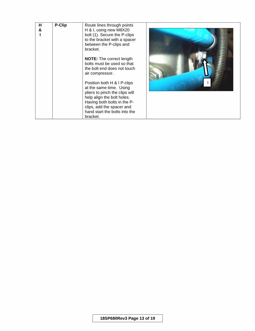
H& I
P-Clip Route lines through points H & I, using new M8X20 bolt (1). Secure the P-clips to the bracket with a spacer between the P-clips and bracket. NOTE: The correct length bolts must be used so that the bolt end does not touch air compressor. Position both H & I P-clips at the same time. Using pliers to pinch the clips will help align the bolt holes. Having both bolts in the P-clips, add the spacer and hand start the bolts into the bracket.
1

18SP680Rev3 Page 14 of 19
J P-Clip Assemble L-bracket, P/N: 23-09130-017 and P-clip P/N: A0019954042 using bolt P/N: 23-10742-075 and lock nut P/N: 23-09336-066. Secure P-clip in the upper hole facing the bolt inwards (1). Using 2 more P-clips, bolt P/N: 23-10742-075 and lock nut P/N: 23-09336-066, assemble both lines together (2). Do this before installing the L- bracket to the breather. NOTE: The L-bracket, P/N: 23-09130-017, may need to be modified slightly on the front of the mounting edge to insure it does not bind on the cap. This must be done before installing it onto the fuel line. NOTICE: The P-clips must be oriented as shown and the lines must be routed as close to the breather housing as possible without rubbing or the clutch arm will hit the fuel lines when the clutch is depressed (4). NOTE: Do not over torque the mounting bolt on the breather housing. Torque bolt onto the breather (3) to 12 N·m (9 lb·ft). Install the plastic oil breather hose. Note: If the electrical line to the block heater is zip-tied to a fuel line, relocate the electrical line to the lifting bracket.
1
2
3
4
18SP680Rev3 Page 15 of 19
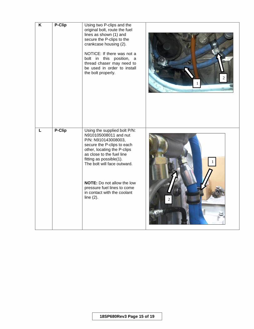
K P-Clip Using two P-clips and the original bolt, route the fuel lines as shown (1) and secure the P-clips to the crankcase housing (2). NOTICE: If there was not a bolt in this position, a thread chaser may need to be used in order to install the bolt properly.
L P-Clip Using the supplied bolt P/N: N910105008011 and nut P/N: N910143008003, secure the P-clips to each other, locating the P-clips as close to the fuel line fitting as possible(1). The bolt will face outward. NOTE: Do not allow the low pressure fuel lines to come in contact with the coolant line (2).
1 2
1
2

18SP680Rev3 Page 16 of 19
M Fuel Line to Fuel Filter Housing (Bottom)
Install the fuel line to the filter housing (1) using two seal rings, P/N: N000000001070. Torque the banjo bolt to 35 N·m (26 lb·ft).
N Fuel
Line to Fuel Filter Housing (Top)
Install adapter P/N: A0089975172 and seal rings P/N: N000000001070 to the filter housing (1). Torque the adapter to 35 N·m (26 lb·ft). Then install the fuel line (2) and seal rings, and torque to 35 N·m (26 lb·ft).
NOTE: Nothing from the chassis side should come within 10mm (static) or 25mm (non-static) of the fuel lines.
60. Torque all remaining banjo bolts to 35 N·m (26 lb·ft). 61. Make sure all the low pressure fuel lines are routed correctly; go through and torque P-clips to 25 N·m (19 lb·ft). There should be a slight amount of slack in the low pressure fuel lines between the P-clip mounting positions. 62. Does the power steering pump have the pressure line on top?
a. Yes, go to the next step. b. No, go to step 67.
63. Install air compressor discharge line hand tight. Note: Discharge line should be routed inside of power steering lines. See Figure 10. 64. Separate the air compressor discharge line (1) from the power steering pressure and suction lines using existing P-clamps (2) and P-clamps from the Kit P/N: 23-11357-02. See Figure 10. 65. Use existing mounting location on the vehicle frame rail to secure the remaining P-clamps.
1
2
1

18SP680Rev3 Page 17 of 19
Figure 10 Air Compressor Discharge Line and Power Steering Pressure Line Routing 66. Install power steering line at the gearbox. Torque to 42-55 N·m (31-41 lb·ft). 67. Does the power steering pump have the suction line on top?
a. Yes, go to the next step. b. No, go to step 70.
68. Route air compressor discharge line between fuel lines and crankcase and hand tighten. 69. Secure air compressor discharge line to old fuel line mounting location with P-clip (1) and torque P-clip to 25 N·m (19 lb·ft). See Figure 11.
Figure 11 Air Compressor Discharge Line Routing and Clipping 70. Torque air compressor discharge line to 20-24 N·m (15-18 lb·ft). 71. Reinstall the clutch rod. Torque clutch rod nuts to 42 to 57 N·m (31 to 42 lb·ft). 72. Actuate the clutch and verify the clutch rod and clutch arm do not contact any components during movement. See Figure 12.
2
1
1

18SP680Rev3 Page 18 of 19
Figure 12 Clutch Arm to Fuel Line Clearance
73. Use supplied tie straps to hold back any components from contacting fuel lines. 74. If fuel filter module has not been replaced, re-torque the fuel filter cap to 25 N·m (18 lb·ft). 75. Inspect return line from fuel filter to tank for any signs of abrasion. Repair if needed. 76. Install fuel tank, torque fuel tank straps to 20 N·m (15 lb·ft), then 40 N·m (30 lb·ft). Refer to the OEM guidelines. 77. Connect the fuel lines to the fuel tank. 78. Install the steps on the fuel tank. 79. Install the fuel water separator. Refer to OEM guidelines. 80. Refill fuel tank. 81. Install the alternator to mounting bracket. Connect all electrical connections. 82. Fit the main drive belt on the belt pulleys. Be careful not to kink, stretch, or otherwise damage the belt. For correct drive belt routing, see Figure 13.
4. Main Figure 13 Main Drive Belt Routing 83. Install the steering shaft to the power steering gear box.

18SP680Rev3 Page 19 of 19
84. Follow these torque settings depending on the size; a. If it is a 7/16–20 pinch bolt and nut, torque to 75 to 88 N·m (55 to 65 lb·ft). b. If it is an M10 x 1.25 pinch bolt and nut, torque to 41 to 47 N·m (30 to 35 lb·ft).
85. Clean mating surface to the intake elbow. 86. Install the charge air elbow to the charge air cooler. Use gasket P/N: A4600980080 to mount the elbow to the mixer housing. Refer to OEM guidelines. 87. Install the radiator support bracket. 88. Tighten the charge air cooler hose clamp. 89. Install the air filter bracket and air filter assembly. Refer to OEM guidelines. 90. Install the fuse box. Refer to OEM guidelines. 91. Prime the fuel system and ensure there are no fuel leaks. If any leaks are found, repair before proceeding.
FIRE To avoid injury from fire, contain and eliminate leaks of flammable fluids as they occur. Failure to eliminate leaks could result in fire.
92. Connect the batteries. 93. Refill power steering reservoir, bleed power steering lines. 94. Start engine to check for proper engine operation and that there are no leaks. If any leaks are found, repair before proceeding.
NOTICE: The injection of ether into the engine during start attempts is strictly prohibited. Injection of ether may result in an uncontrolled internal engine explosion that could cause engine damage.
95. Shut engine off. 96. Install engine cover and passenger seat inside the truck. 97. Torque seat mounting bolts to 25 to 29 N·m (18 to 21 lb·ft). 98. Install fender and inner splash shield. 99. Install wheel. Tighten the wheel lug nuts to OEM specification. 100. Remove jack stands. 101. Close hood.
Specifications are subject to change without notice. Detroit Diesel Corporation is registered to ISO 9001:2008. Copyright © Detroit Diesel Corporation. All rights reserved. Detroit™ is a brand of Detroit Diesel Corporation, a Daimler company. 18SP680Rev3 1311 As technical advances continue, specifications will change. Printed in U.S.A.