11. completing the fuselage - home | falcondesign s-series...jabiru aircraft fit cowls reference:...
TRANSCRIPT

11. Completing the Fuselage
Cowls
1
PROCEDURE NAME PROC NO. ISSUE DATE PAGE Completing the Fuselage 11.0 1 230399 -

JABIRU AIRCRAFT
FIT COWLS
Reference: Photo 11-21(A-N) Materials required: Card 13, Upper and Lower cowl, oil door, NACA duct. Procedure: Note: Pre fit engine with ram-air ducts, exhaust and oil cooler Top Cowl 1) Cut out front off cowl as marked to fit over crankshaft prop flange extension. 2) Trim flange to allow cowl to fit joggle (recess) on the fuse. Refer photo 11-21A
Trim flangeto suit fuse
Photo 11-21A flange cut out
PROCEDURE NAME PROC NO. ISSUE DATE PAGE Fit Cowls 11.21 3 290800 1
3) Trim flange around cylinder heads to ensure cowl does not touch engine. Refer photo 11-21B

JABIRU AIRCRAFT
Photo 11-21B Flange cut for cylinder head
4) Trim rear edge to fit fuse (moulded skin front) 5) Drill three 1\4’’ holes in rear flange for cowl pins. Refer photo 11-21C. Side holes are
100mm up from waterline flange
Photo 11-21C Holes for cowl pins
PROCEDURE NAME PROC NO. ISSUE DATE PAGE Fit Cowls 11.21 3 290800 2
to fit Trim flangearound
100mm from flange
Center line of cowl

JABIRU AIRCRAFT
6) Place 15mm x 15mm x 1\4’’ ply or a suitable equivalent on the m-air ducts and the starter to act as a spacer. Refer photo 11-21D (1 & 2)
11-21D 1 & 2 – Placing spacers on air ducts and starter. 7) Place cowl on airframe and secure with tape, mark cowl pin holes onto fuse from
underneath by transferring cowl holes onto moulded skin front. Drill out marked holes to ¼”.
8) The three 1\4’’ cowl pins P/NO 101229N can now be fitted to the cowl, use a black nut on the rear of the flange and the nyloc nut on the front of the flange, lock the two nuts together to secure pins. Refer photo 11-21E
PROCEDURE NAME PROC NO. ISSUE DATE PAGE Fit Cowls 11.21 3 290800 3
¼” ply packers

JABIRU AIRCRAFT
Photo 11-21E Cowl pins with nyloc nuts on front of flange
Photo 11-21F(1) Red Lubron square Photo 11-21F(2)
9) Drill and attach red Lubron Square P/NO 1039094 to cover and act as a lead in over holes in the moulded skin front, attach with P\NO M4x16 and suitable nuts and washers. Refer photo 11-21F(1&2)
PROCEDURE NAME PROC NO. ISSUE DATE PAGE Fit Cowls 11.21 3 290800 4
nyloc nut on this side
M4x16 countersunk machine screw
Red Lubron Block

JABIRU AIRCRAFT
Lower cowl 1) Trim waterline flange to suit fuse as per top cowl. Refer photo 11-21G
Photo 11-21G –Trim waterline flange 2) Place some small pieces of insertion rubber on flange to simulate 1mm rubber,
which will be glued to flange after painting. Refer photo 11-21H. 3) Fit lower cowl to top, ensure that cowl clip slot lines up and the cowl does not
touch the engine, exhaust or oil cooler. 4) Mark out three evenly spaced holes for cowl attachment. Refer photo 11-21H on
either side. Start with the top hole 11mm down from the flange & half out from joggle. NOTE: Use 6 gauge self-tapers to secure cowl initially, that way the holes may be moved if necessary.
5) Once fit is satisfactory, fit retain nuts P\NO MS1069-L08 to fuse, secure with two TAPK 3-3 Rivets P\NO PH9929N. Refer photo 11-21I
PROCEDURE NAME PROC NO. ISSUE DATE PAGE Fit Cowls 12 1 230399 -
Cut flange to suit Joggle

JABIRU AIRCRAFT
Photo 11-21H
Photo 11-21 I – Lower cowl attachment
PROCEDURE NAME PROC NO. ISSUE DATE PAGE Fit Cowls 12 1 230399 -
First screw 11mm down from top flange
Retain nut

JABIRU AIRCRAFT
6) Fit cowl clips P\NO PH1249N to bottom cowl with 73AS 5-8 rivets . Refer photo
11-21J.
Photo 11-21J – Fitting cowl clips to bottom cowl
Photo 11-21KWasher on inside of cowl on rivet
NOTE: Place a flat washer on the inside of the cowl on each rivet P\NO 5\32” brass. Refer to Photo 11-21K.
PROCEDURE NAME PROC NO. ISSUE DATE PAGE Fit Cowls 12 1 230399 -
Brass washer on rivet

JABIRU AIRCRAFT
7) Fit cowl safety bracket P\NO101239N right at the top of the slot with 73AS 4-6 rivets. Refer photo 11-21L.
Photo 11-21L Top Cowl 8) With lower cowl catch & the upper safety catch fitted, place the upper cowl catch
clipped onto the bottom cowl. Allow the leaver of the top latch to be half over centred. This will give you the right compression & position to secure the top latch. Refer 11-21 M.
Photo 11-21M – fitting upper cowl to bottom cowl catch
PROCEDURE NAME PROC NO. ISSUE DATE PAGE Fit Cowls 12 1 230399 -
Top Cowl Safety bracket
Top Cowl catch
Half over centred

JABIRU AIRCRAFT
9) Drill two 3/16” holes in top cowl using the latch as a template and attach with
73AS5-8 rivet and washer. 10) Fit cowl retaining safety pins P\NO 1056044 to lower cowl and cut a slot into
top cowl for pins to Locate in. Refer photo 11-21N(1,2,3&4). Secure pins with 73AS 4-6 rivets with flat washers on the inside as above.
11-21N(1) 11-21N(2)
11-21N(3) 11-21N(4) NOTE: R-clip P/No PH10259N is a safety clip which goes through cowl safety bracket once clips have been done up.
PROCEDURE NAME PROC NO. ISSUE DATE PAGE Fit Cowls 12 1 230399 -
Cowl retaining safety pin Slot for
retaining pin
Cowl Saftey Catch

JABIRU AIRCRAFT
Bottom Cowl to Top Cowl Temporary place Top Cowl onto Bottom Cowl with insertion rubber on lower cowl.
OIL DOOR 1) Trim door to suit recess in top cowl 2) Fit hinge and cam lock as per drawing no 1068073 (Door assy oil filler access)
PROCEDURE NAME PROC NO. ISSUE DATE PAGE Fit Cowls 12 1 230399 -
Lubron Cowl pin position block
M4 x 16mm
¼” hole for Cowl pin
Molded skin front

JABIRU AIRCRAFT
PROCEDURE NAME PROC NO. ISSUE DATE PAGE Fit Cowls 12 1 230399 -
Oil door 1068073

JABIRU AIRCRAFT NACA DUCT 1) Install, as per drawing no 9115004-1 (Air inlet duct installation) & photos
PROCEDURE NAME PROC NO. ISSUE DATE PAGE Fit Cowls 12 1 230399 -

JABIRU AIRCRAFT
PROCEDURE NAME PROC NO. ISSUE DATE PAGE Fit Cowls 12 1 230399 -

JABIRU AIRCRAFT
12. Wings, Flaps, Ailerons and Struts
Fit Aileron Hinges Reference: Drawing 20270K2 Photo 12.1 Parts Required: 2007092 Aileron LS 200809N Aileron RS 2001394 Hinge 3/16 A1 (4) 2001694 Hinge Pin (4) PH0059N Rivet 73 AS 6-4 (16) Materials Required: LC3600 Epoxy Resin LC3600 Epoxy Hardener Fibre Flock Procedure: 2. Position the hinges as per Drawing 20270K2 and drill the rivet holes 3. Mix Resin/Hardener/Flock and bed the hinge leaves in place. 4. Rivet the hinge leaves in place, prior to curing.
Photo 12.1 – An installed hinge leaf.
PROCEDURE NAME PROC NO. ISSUE DATE PAGE Fit Aileron Hinges 12.1 1 230399 1

JABIRU AIRCRAFT
Drawing 20270K2 – Aileron Assembly Details
PROCEDURE NAME PROC NO. ISSUE DATE PAGE Fit Aileron Hinges 12.1 1 230399 2

JABIRU AIRCRAFT
Fit Ailerons Reference: Drawings 2033091 and 20210K1 Photos 12.2(a), 12.2(b), 12.2(c) and 12.2(d) Parts Required: 2021091 Wing LS 202209N Wing RS 2027092 Aileron LS 202809N Aileron RS 2036034 Aileron reinforcement – Left 203703N Aileron Reinforcement – Right 2038034 Aileron Reinforcement – Centre (2) 2001394 Hinge Leaf 3/16 A1 (4) 203903N Aileron Attachment Plate Reo (2) PH0409N 2-Lug Anchor Nut (4) PH0399N Rivet (8) PH0059N Rivet 73 AS 6-4 (16) Material Required: LC3600 Resin LC3600 Hardener Fibre Flock AF303 Glass Cloth Procedure: 1. Trim area 960 x 15 on top of the wing and cut hole for aileron cable as
indicated in photo 12.2(a).
Photo 12.2(a) – Areas to be trimmed
PROCEDURE NAME PROC NO. ISSUE DATE PAGE Fit Ailerons 12.2 1 230399 1

JABIRU AIRCRAFT
2. Turn the wind upside down 3. Remove peel cloth from hinge Reo (reinforcement) and flap attachment areas. 4. Position the Aileron Attachment Plate and flock into position. Photo 12.2(b)
shows how the plate is held in place.
Photo 12.2(b) – Aileron attachment plate positioning
5. Position the Aileron Hinge Reinforcements (Left or Right and Centre) and bond in with flock. Refer to photo 12.2(c )
Note: There is an outboard left and right hinge reinforcement but the inboard hinge reinforcements are the same. 6. Lay 2 x 220 x 160 AF303 over each hinge reinforcement. 7. Lay 1 x 1000 x 160 over both hinge reinforcements and along the Aileron
reinforcement plate, refer to photo 12.2(d). 8. Allow to cure 9. Position the aileron assembly and mark the rivet holes. 10. Drill the holes for the rivet, also drill the holes for the anchor lug nut. 11. Sand back surface of hinge and clean with acetone. 12. Bond the hinges with flock. 13. Rivet the 2-lug anchor nut for the retaining cap into place, refer to photo
12.2(c ). 14. Allow to cure then assemble with aileron to check movement.
PROCEDURE NAME PROC NO. ISSUE DATE PAGE Fit Ailerons 12.2 1 230399 2

JABIRU AIRCRAFT
Photo 12.2(c ) – Aileron hinge reinforcement
Photo12.2(d) – Wing Aileron assembly
PROCEDURE NAME PROC NO. ISSUE DATE PAGE Fit Ailerons 12.2 1 230399 3

JABIRU AIRCRAFT
Drawing 2033091 – Wing Assembly
PROCEDURE NAME PROC NO. ISSUE DATE PAGE Fit Ailerons 12.2 1 230399 4

JABIRU AIRCRAFT
Drawing 20210K1 – Wing Assembly Detail Kit
PROCEDURE NAME PROC NO. ISSUE DATE PAGE Fit Ailerons 12.2 1 230399 5

JABIRU AIRCRAFT
Fit Flaps Reference: Drawings 2033091 and 20210K1
- refer Procedure 12.2 at pages 4 & 5 respectively. Photos 12.3(a), 12.3(b) and 12.3(c )
Parts Required: 2021091 Wing LS 202209N Wing RS 2029092 Flap LS 203009N Flap RS 2026094 Flap Mounting Arm (6) Material Required: LC3600 Resin LC3600 Hardener Fibre Flock AF303 Glass Cloth Procedure: 1. Locate flap hinge brackets using flaps as a jig and clamp to wing, as shown in
photo 12.3(a)
Photo 12.3(a) - Clamping the flap into place
2. Insert AN3 bolt into each hinge. Refer to photo 12.3(b) 3. Sand each hinge lightly. 4. Mix LC3600/Fibreflock and bond each hinge to the wing.
PROCEDURE NAME PROC NO. ISSUE DATE PAGE Fit Flaps 12.3 1 230399 1

JABIRU AIRCRAFT
5. Apply AF303 1 x 200 x 100, 1 x 200 x 150, 1 x 200 x 200 to each hinge
attachment, refer to photo 12.3(c ). Pay particular attention to the root of the hinge, use suitable ply pieces to hold these reo pieces under end plug until cured.
6. Apply peel cloth to glassed hinge areas. 7. Cure: then remove peel cloth and dress.
Photo 2.3(b) – Positioning the hinge
Photo 12.3(c ) – Glassing the hinges on
PROCEDURE NAME PROC NO. ISSUE DATE PAGE Fit Flaps 12.3 1 230399 2

JABIRU AIRCRAFT
Fit Aileron Cable Reference: Drawing 20400K4 Parts Required: 2003E94 Aileron Cable Attachment Plate PC00294 Aileron Cable PC0089N Cable Clamp PC0099N Cable Anchor AN3-5A Bolt (2) AN960-10 Washer (2) MS20365-1032 Nut (2) PB0019N Rod End – Female PH0636N Nut Jan S/S 3/16 UNF Material Required: K219 5 minute Epoxy LC3600 Resin LC3600 Hardener Fibre Flock AF303 Glass Cloth Procedure: 1. Tie Aileron Cable to string which has been factory fitted to Aileron Cable
channel in wing. Pull the Aileron Cable into position and discard the string. 2. Fit Aileron Cable Attachment Plate as per instructions detailed on drawing
20400K4. 3. Mount cable with Cable Clamps, Cable Ailerons and hardware as shown in
drawing 20400K4. 4. Fit Rod End – Female and locknut to end of cable.
PROCEDURE NAME PROC NO. ISSUE DATE PAGE Fit Aileron Cable 12.4 1 230399 1
5. Repeat Items 1 – 4 for other wing.

JABIRU AIRCRAFT
Drawing 20400K4 – Aileron Cable Att. Plate Details
PROCEDURE NAME PROC NO. ISSUE DATE PAGE Fit Aileron Cable 12.4 1 230399 2

JABIRU AIRCRAFT
Fitting Wings, Struts and Fairing to Fuselage – Trial Fitment Reference: Drawing 2033091 (Refer Procedure 12.2) Parts Required: 2021091 Wing (2) AN3-10A Bolt (6) AN960-10 Washer (14) AN960-416 Washer (20) MS20365-1032 Nut (13) PH0139N Screw 6g x ½” (8) PH0646N Screw 6g x ¼” (30) AN4-13A Bolt (4) AN960-428 Nut (4) AN5-15A Bolt (2) AN960-156 Washer (2) MS20365-428 Nut (2) 300819N Flap Push Rod (2) PB0009N Rod End Male (4) PH0636N Nut Jam 3/16 UNF (4) AN3-12A Bolt (2) AN3-7A Bolt (6) 2035094 Spacer Sleeve (6) 3027094 Cable Wedge (2) PH0259N R-Pin (2) PB0019N Rod End Female (2) Material Required: Procedure: 1. While the wings are still not fitted to the aircraft attach aileron cable to aileron
horn with AN3-10A bolt. Ensure that here is an AN960-10 washer on each side of the rod nut and that a AN960-416 washer is installed on the outboard side of the rod end so as to ensure that the cable is not released, should the bearing fail. Complete with MS20365-1032 nut.
2. Fit perspex inspection cover to recess in bottom outboard section of wing with 6g x ½” pan screws.
3. Repeat steps 1 – 2 for other wing. YOU ARE NOW READY TO TRIAL FIT THE WINGS AND WILL PROBABLY NEED THE ASSISTANCE OF ONE OTHER PERSON. 4. Position the wing on the floor taking care not to damage the wing strut
attachment lug. At this stage the Aileron should be attached to the wing but the Flap should not be attached.
PROCEDURE NAME PROC NO. ISSUE DATE PAGE Fitting Wings etc – Trial Fitment 12.5 1 230399 1

JABIRU AIRCRAFT
5. Lift the inboard (root) end of the wing into position (Aileron Cable through
hole in fuselage) and attach to the wing attachment fittings in the fuselage with AN4-13A bolts. AN960-416 washers and MS20365-428 nuts.
6. Lift the outboard (tip) end of the wing and attach the Wing Strut with AN5-15A bolts, AN960-516 washers and MS20365-428 nuts at the wing end and AN5-15A bolts, AN960-516 washers and MS20365-428 nuts at the fuselage end.
Note: DO NOT OVERTIGHTEN THESE BOLTS. They should be just tight enough to prevent rotation. Overtightening may result in failure of the Wing Strut Lugs. 7. Before attaching Flaps, fit push rod 160mm Aluminium rods to flap with male
ball joints and jam nuts in each end. On the flap end of the push rod, fit 1 x AN3-12A Bolt, 5 x 960-10 washers, 1 x MS20365-1032 nut, 1 x 960-416 washer on each side.
8. Fit the flaps to the Wings with AN3-7A bolts, 20365-1032 nuts, AN960-1032 washers and 8mm ¼” steel tube Spacers Flap as shown in Drawing 2033091.
9. Attach to the flap drive with AN3-10A Bolt ensuring an AN960-416 washer is fitted on the outside of the rod end bearing.
10. Fit a rod end – female to the inboard end of the aileron cable together with a jam nut PH0636N.
11. Anchor aileron cable to seatback restraint with cable wedge and R. Pin. 12. Fit rod end – female to aileron bellcrank with AN3-10A bolt, AN960-416
washer x 1, AN960-1032 washer. 13. Repeat steps 4 – 12 for other wing. 14. Ensure aileron and flap controls operate smoothly. 15. Fit wing root fairings with 6g x ¼” self tapping screws. 16. Fit lower wing strut fairings with 6g x ¼” self tapping screws. Be careful not
to drill holes in wing strut beam under seats. 17. Fit upper wing strut fairings with 6g x ¼” self tapping screws. Be careful not
to frill holes in wing spar which is 25mm each side of wing attachment lug. 18. Wings are now able to be removed for preparation and painting. Remember to
remove the flaps and aileron cables from seatback anchors, before removing the wings.
PROCEDURE NAME PROC NO. ISSUE DATE PAGE Fitting Wings etc – Trial Fitment 12.5 1 230399 2

JABIRU AIRCRAFT
Assemble Flap Handle Reference: Drawing 3066092 Parts Required: 3020094 Flap Position Pin (1) MS24665-132 Cotter Pin (1) AN4-11 Bolt (1) AN310-4 Nut (1) 3042094 Aluminium Washer (2) 3041094 Nylon Washer (2) 3059094 Flap Handle Assy (1) 3067094 Spacer Sleeve (4) 305209N Push Rod Inner (1) AN960-416 Washer (6) AN3-6A Bolt (1) 3003092 Flap Control Rod Assy (1) 3051094 Push Rod Flap (2) AN316-3 Nut (6) MS20365-1032 Nut (8) AN3-11A Bolt (6) AN960-10 Washer (20) PB0009N Rod End Male (6) Material Required: K219 5-min Epoxy Fibre Flock Procedure: 1. Before gluing flap handle cover to flap handle place nylon and aluminium washer
inside first then glue together with K219 5-min and flock on the inside of the flap handle cover, then place onto flap handle. Allowing the 5 min to bond all the way around. Then cut and drill as per drawing. After the flap handle is complete with the holes drilled and cuts made, you will have to fit the male ball joint and pin position flap lever.
2. Counter sink flap handle enough to the head of the bolt is flush (Shown is section BB on the drawing) then assemble as per drawing 3066092.
3. Bolt pin flap lever on the flap handle as shown in section AA on drawing 3066092.
4. Fit flap handle to flap mount plate as per drawing 3066024 section BB.
PROCEDURE NAME PROC NO. ISSUE DATE PAGE Assemble Flap Handle 12.6 1 230399 1

JABIRU AIRCRAFT
Drawing 3066092 – Flap Assy Controls
PROCEDURE NAME PROC NO. ISSUE DATE PAGE Assemble Flap Handle 12.6 1 230399 2

JABIRU AIRCRAFT
Fitting Push Rod from Flap Handle to Flap Shaft Reference: Drawing 3066092 (Refer procedure 12.6) Parts Required: 305209N Push Rod Inner PB0009N Rod End Male (2) PH0636N Nut Jam S/S 3/16 UNF (2) AN3-11A Bolt (2) AN960 –10 Washer (8) AN960-416 Washer (2) MS20365-1032 Nut (2) Material Required: Procedure: 1. Screw aluminium push rod inner onto the male ball joint and jam nut on the flap
handle. Screw a male ball joint and jam nut onto the other end of the push rod. 2. Bolt male ball joint onto flap shaft and flap handle as per drawing 3066092
Section CC.
PROCEDURE NAME PROC NO. ISSUE DATE PAGE Fitting PushRod from Flap Handle to Shaft 12.7 1 230399 1

JABIRU AIRCRAFT
2
THIS PAGE IS INTENTIONALLY LEFT BLANK
PROCEDURE NAME PROC NO. ISSUE DATE PAGE Prep, Painting & Finishing Proc 13.0 1 230399 -

JABIRU AIRCRAFT
3
13 Preparation, Painting & Finishing Procedure
PROCEDURE NAME PROC NO. ISSUE DATE PAGE Prep, Painting & Finishing Proc 13.0 1 230399 -
JABIRU AIRCRAFT
1
Disassembly Prior to Painting: Reference: Parts Required: Procedure: 1. Prior to this stage you should have fitted all the components to the aircraft.
These are now removed for preparation and painting. 2. Remove: Fairings
Flaps Wings Wing Struts Ailerons Wheel Spats Elevator Rudder Ventral Fin Doors Engine Cowling Propeller Spinner Noseleg Assembly
It is recommended that hardware pertaining to each assembly be kept in separate marked bags. You may also wish to remove the engine, prior to painting.
3. Prepare for Painting – See Procedure 13.2 4. Using masking tape, mask all fittings and areas not requiring painting.
PROCEDURE NAME PROC NO. ISSUE DATE PAGE Disassembly Prior to Painting 13.1 1 230399 1
JABIRU AIRCRAFT
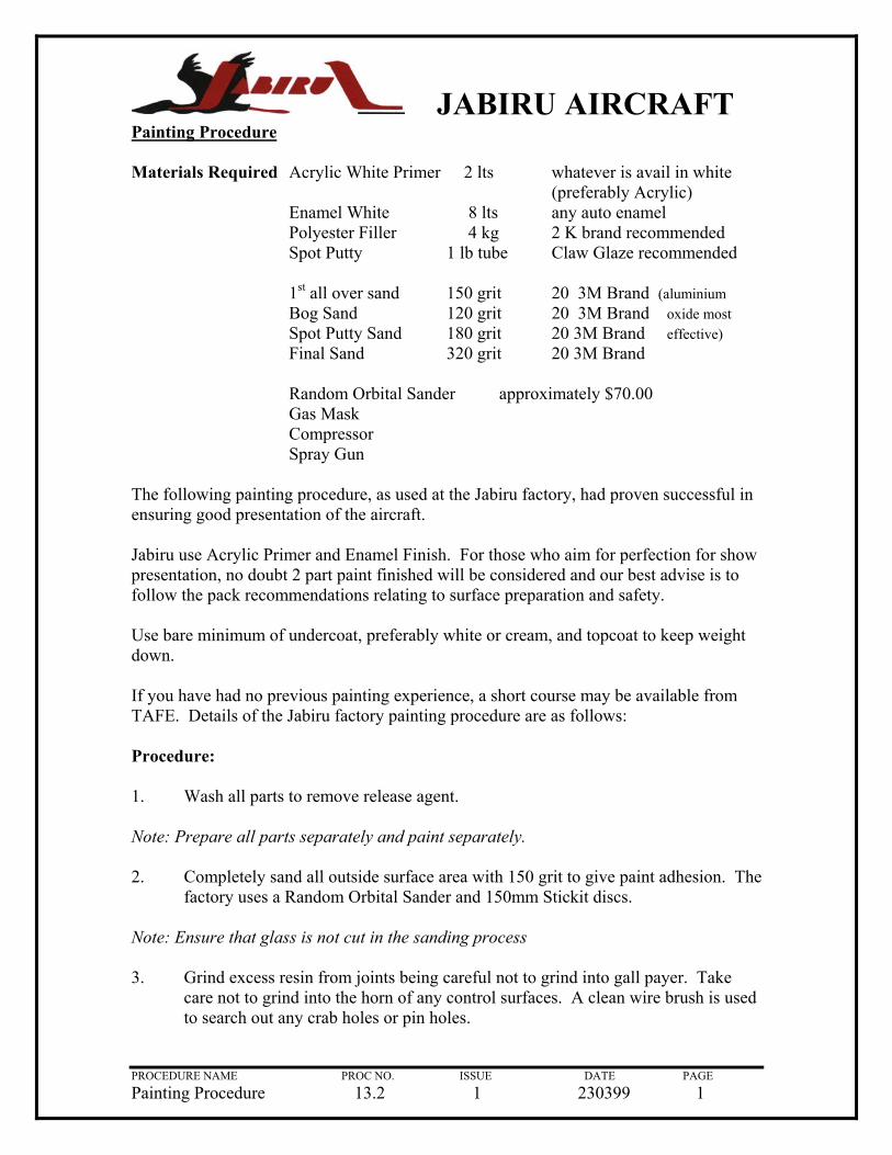
Painting Procedure Materials Required Acrylic White Primer 2 lts whatever is avail in white (preferably Acrylic) Enamel White 8 lts any auto enamel Polyester Filler 4 kg 2 K brand recommended Spot Putty 1 lb tube Claw Glaze recommended 1st all over sand 150 grit 20 3M Brand (aluminium Bog Sand 120 grit 20 3M Brand oxide most Spot Putty Sand 180 grit 20 3M Brand effective) Final Sand 320 grit 20 3M Brand Random Orbital Sander approximately $70.00 Gas Mask Compressor Spray Gun The following painting procedure, as used at the Jabiru factory, had proven successful in ensuring good presentation of the aircraft. Jabiru use Acrylic Primer and Enamel Finish. For those who aim for perfection for show presentation, no doubt 2 part paint finished will be considered and our best advise is to follow the pack recommendations relating to surface preparation and safety. Use bare minimum of undercoat, preferably white or cream, and topcoat to keep weight down. If you have had no previous painting experience, a short course may be available from TAFE. Details of the Jabiru factory painting procedure are as follows: Procedure: 1. Wash all parts to remove release agent. Note: Prepare all parts separately and paint separately. 2. Completely sand all outside surface area with 150 grit to give paint adhesion. The
factory uses a Random Orbital Sander and 150mm Stickit discs. Note: Ensure that glass is not cut in the sanding process
PROCEDURE NAME PROC NO. ISSUE DATE PAGE Painting Procedure 13.2 1 230399 1
3. Grind excess resin from joints being careful not to grind into gall payer. Take care not to grind into the horn of any control surfaces. A clean wire brush is used to search out any crab holes or pin holes.

JABIRU AIRCRAFT
4. Breathing respirator with painting cartridges right from initial sanding through to painting.
Hint: Body Filler sets quickly in high temperatures particularly when larger mixes are necessary. Use cold packs under the Body Filler board to extend setting time.
5. Follow instructions carefully and experiment with setting times.
6. On large radius (e.g. sides of fuselage) an extra large home made spatular (9” tin plate) is very hand when applying Body Filler.
7. When filling up to window edges, grind chamfer onto edge of window to give depth for bog adhesion.
CAREFUL!! THE GEL COAT IS MICRO THIN, SO SANDING IS ALWAYS A CAREFUL PROCEDURE. IF GEL COAT IS INADVERTENTLY PENETRATED DO NOT CONTINUE SANDING INTO STRUCTURAL GLASS.
8. With the surface satisfactorily prepared white primer is required only on the discoloured areas (i.e. Body Filled areas). Pin holes become evident after the primer is applied so use “spot putty” to fill. Be careful and meticulous to find all pin holes because primer and enamel will not fill holes.
Inside the Fuselage
9. Do not try to fill the grain in the exposed glass and do not sand the exposed surfaces to improve the visual aspect. DO NOT CUT GLASS!.
10. The factory uses a low pressure pot gun for spraying at pressures from 60-100 psi.
11. It is mandatory that exterior colour is WHITE only broke if desired, by pin strips on the vertical surfaces (i.e. Sides of fuselage) but not horizontal surfaces (i.e. top of wings or fuselage) as the heat build up under the tape in hot sun is considerable.
12. After filling all pin holes spray another coat of primer on the discoloured areas. An all over primer coat is not required over the gel coat as gel coat is a sufficient undercoat.
13. The final rub is with 320 grit all over and if satisfied with the surface preparation (remember paint will simply change colour not hide lumps, bumps, scratches and holes) blow off the dust and give an all over wipe with a tack cloth to pick up the final dust particles.
PROCEDURE NAME PROC NO. ISSUE DATE PAGE Painting Procedure 13.2 1 230399 2
14. Wash down the floor of the spray area to settle dust and proceed to spray as per your selected technique.

JABIRU AIRCRAFT
15. You are now ready to spray final coat. GOOD LUCK!
PROCEDURE NAME PROC NO. ISSUE DATE PAGE Painting Procedure 13.2 1 230399 3

JABIRU AIRCRAFT
Registration Marks
You will need to establish the requirements in your country for the type, size, shape and location of registration numbers or letters.
In Australia, for AUF registered aircraft, these are detailed in the AUF Operations Manual. For VH registered aircraft, they are detailed in Civil Aviation Regulations 16-20.
Most Authorities have a facility which enables specific registration marks to be reserved.
You should contact your Authority early in your project if you wish to reserve specific marks
PROCEDURE NAME PROC NO. ISSUE DATE PAGE Registration Marks 13.3 1 230399 1

JABIRU AIRCRAFT
THIS PAGE IS INTENTIONALLY LEFT BLANK
PROCEDURE NAME PROC NO. ISSUE DATE PAGE Instruments, Avionics etc 14.0 1 230399

JABIRU AIRCRAFT
14. Instruments, Avionics and
Upholstery
PROCEDURE NAME PROC NO. ISSUE DATE PAGE Instruments, Avionics etc 14.0 1 230399

JABIRU AIRCRAFT
Painting Cockpit Interior
Most of the work will have been completed prior to joining the two halves of the fuselage.
However other areas requiring painting will now be obvious.
Complete the interior painting remembering not to cut glass by sanding and use a minimum of paint so as to maintain a minimum weight aircraft.
PROCEDURE NAME PROC NO. ISSUE DATE PAGE Painting Cockpit Interior 14.1 1 230399 1

JABIRU AIRCRAFT
Carpeting
In finishing out your aircraft it is easy to add weight unnecessarily. Remember that the objective is to achieve a minimum weight/maximum performance aircraft.
Upholstery patterns are included in your kit and these contain full instructions.
We recommend that you consult your Authority to establish materials which meet their requirements for light aircraft applications.
Our optional carpeting kit is available from jabiru in the following colours:
- Grey
- Green
PROCEDURE NAME PROC NO. ISSUE DATE PAGE Carpeting 14.2 1 230399 1
- Pink

JABIRU AIRCRAFT
Seat Covers
The comments at Procedure 14.2 also apply to seat covers.
Genuine Lambs wool covers are accepted by most Authorities as being flameproof. They also provide excellent comfort for long distance flying.
Ensure that upholstery does not interfere with flight controls.
PROCEDURE NAME PROC NO. ISSUE DATE PAGE Seat Covers 14.3 1 230399 1

JABIRU AIRCRAFT
Fit Instruments to Main Panel
The recommended basic VFR/Day instrument layout is shown in drawing 9027093 (page 2).
Aircraft Instruments should be installed with brass instrument screws and nuts. Engine instruments are installed using the attachments provided with the instruments.
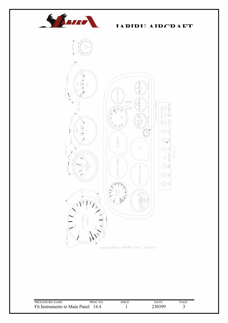
A recommended layout for an extended panel with Vacuum Instruments is shown in drawing 9029043 (page 3).
PROCEDURE NAME PROC NO. ISSUE DATE PAGE Fit Instruments to Main Panel 14.4 1 230399 1
The compass should be fitted to the bracket provided above the windscreen, thereby ensuring that it is not effected by electromagnetic interference from the engine.

JABIRU AIRCRAFT
Drawing 9027093 – Instrument Panels Jabiru
PROCEDURE NAME PROC NO. ISSUE DATE PAGE Fit Instruments to Main Panel 14.4 1 230399 2
JABIRU AIRCRAFT
PROCEDURE NAME PROC NO. ISSUE DATE PAGE Fit Instruments to Main Panel 14.4 1 230399 3

JABIRU AIRCRAFT
Fitting Main Panel and Connecting Instruments
General
The instrument panel assembly consists of a stationary and a shock-mounted panel. The stationary lower panel contains switches and fuses which are not sensitive to vibration. The shock-mounted panel contains flight instruments which ARE affected by vibration. The instruments are screw-mounted to the panel.
Installation
The lower panel will have been previously installed. Refer Procedure 10.26. The Instrument Panel Mount Brackets will have been previously installed at Procedure 10.25.
The main shock-mounted panel is secured to the Firewall Instrument Panel attachments with rubber shock-mounts.
To install the main panel:
1. Clamp upper and lower panels together before setting up the mounting points, so that the rear of both panels are flush.
Note: Trimming a small section of the rear part of the upper panel may be necessary
2. Place 2x2mm spacers between the upper and lower panels only at the front. With grommets and bushes in the upper panel, drill through the lower panel to position your retained nuts
3. Position the instrument panel aluminium mount brackets LHS and RHS onto the firewall into pre-drilled holes and rivet into place with 73 AS 6-6.
4. Mount upper and lower panels onto the mounting brackets still clamped together. Drill 3/16” holes either side of the lower instrument panel flanges drilling through the firewall
5. Rivet the lower panel in place with 73 AS 6-6 rivets having the head of the rivet on the engine side of the firewall.
Pitot & Static Systems
The pitot system conveys ram air pressure to the airspeed indicator. The static system vents vertical speed indicator (if fitted), altimeter and airspeed indicator to atmospheric pressure through plastic tubing connected to a static port.
PROCEDURE NAME PROC NO. ISSUE DATE PAGE Fitting Main Panel & Connect Instr 14.5 1 230399 1

JABIRU AIRCRAFT
Maintenance
Proper maintenance of pitot and static system is essential for proper operation of the altimeter, airspeed indicator and vertical speed indicator (if fitted). Leaks, moisture and obstructions in the pitot system will result in false airspeed indications, while static system malfunctions will affect reading of all three instruments. Cleanliness and security are the principal rules for system maintenance. The pitot tube and static port MUST be kept clean and unobstructed.
Static Pressure System Inspection and Leakage Test
The following procedure outlines inspection and testing of the static pressure system, assuming that the altimeter has been tested and inspected in accordance with current Regulations.
1. Ensure the static system is free from entrapped moisture and restrictions.
2. Ensure no alterations of airframe surface have been made which would effect the relationship between air pressure in the static pressure system and true ambient air pressure for any flight configuration.
3. Attach a source of suction to static pressure source opening. Figure 12.4 shows one method of obtaining suction.
4. Slowly apply suction until the altimeter indicates a 1000 foot increase in altitude.
CAUTION
When applying or releasing suction, do not exceed the range of either vertical speed indicator or airspeed indicator.
5. Cut off suction source to maintain a “closed” system for one minute. Leakage shall not exceed 100 feet altitude loss as indicated on the altimeter
6. If leakage rate is within tolerance, slowly release suction source.
Note: If leakage exceeds maximum allowable, first tighten all connections, then repeat leakage test. If leakage rate still exceeds maximum allowable use the following procedure:
7. Disconnect static pressure lines from airspeed indicator and vertical speed indicator. Use suitable fittings to connect lines together so that the altimeter is the only instrument still connected into the static pressure system
PROCEDURE NAME PROC NO. ISSUE DATE PAGE Fitting Main Panel & Connect Instr 14.5 1 230399 2
8. Repeat leakage test to check whether static pressure system or the bypassed instruments are the cause of the leakage. If instruments are at fault, they must be repaired by an “appropriately authorised repair station”, or replaced. If static pressure system is at fault, use the following procedure to locate the leakage.

JABIRU AIRCRAFT
9. Attach a source positive pressure to the static source opening. Drawing 9017093 shows one method of obtaining positive pressure.
CAUTION
Do not apply positive pressure with airspeed indicator or vertical indicator connected to the static pressure system
10. Slowly apply positive pressure until altimeter indicates a 500 foot decrease in altitude and maintain this altimeter indication while checking for leaks. Coat line connectors and static source flange with solution of mild soap and water, watching for bubbles to locate leaks.
11. Tighten leaking connections. Repair or replace parts found to be defective.
12. Reconnect airspeed and vertical speed indicators into static pressure system and repeat leakage test steps 3 through 6.
Pitot System Inspection and Leakage Test
To check pitot system for leaks, place a piece of rubber or plastic tubing over pitot tube, close opposite end of tubing and slowly roll up tube until airspeed indicator registers in the cruise range. Secure tube and after a few minuted recheck airspeed indicator. Any leakage will have reduced the pressure in the system, resulting in a lower airspeed indication. Slowly unroll tubing before removing it, so pressure may be released gradually. Otherwise instrument may be damaged. If test reveals a leak in the system, check all connections for tightness.
Blowing out Lines
Condensation may collect at points in the pitot system and produce a partial obstruction. To clear line, disconnect airspeed indicator. Using low pressure air, blow from indicator end of line toward pitot tube.
CAUTION
Never blow through pitot or static lines towards the instruments
Like pitot lines, static lines must be kept clear and connections tight. When necessary, disconnect static line at first instrument to which it is connected, then blow line clear with low pressure air. Check all static pressure lines for tightness. If hose or hose connections are used, check for general condition and clamps for security. Relace hose which has cracked, hardened or shows signs of deterioration.
PROCEDURE NAME PROC NO. ISSUE DATE PAGE Fitting Main Panel & Connect Instr 14.5 1 230399 3

JABIRU AIRCRAFT
Removal & Installation of Components
To remove pitot mast, remove the two screws fastening it to the wing strut and pull it out from the strut far enough to disconnect the pitot line.
The static mast is fixed and cannot be removed. To gain access to disconnect the static tube from the static mast, remove the VHF antenna cover at the top of the fin. Pitot and static tubing is removed in the usual manner.
Installation of tubing will be simplified if a guide wire is drawn in as the tubing is removed. When replacing tubing and fittings, tighten connection firmly, but avoid overtightening and distortion of fittings or tubing.
Trouble Shooting
Refer to pages 12/06 – 12/12 of Jabiru Aircraft Service Manual.
Engine Instruments
Details instructions covering the installation of each engine instrument are enclosed with the instrument.
PROCEDURE NAME PROC NO. ISSUE DATE PAGE Fitting Main Panel & Connect Instr 14.5 1 230399 4

JABIRU AIRCRAFT
PROCEDURE NAME PROC NO. ISSUE DATE PAGE Fitting Main Panel & Connect Instr 14.5 1 230399 5

JABIRU AIRCRAFT
Drawing 5045094 – Static/Pitot Assy
PROCEDURE NAME PROC NO. ISSUE DATE PAGE Fitting Main Panel & Connect Instr 14.5 1 230399 6

JABIRU AIRCRAFT
Drawing 9017093 – Static Test Equipment
PROCEDURE NAME PROC NO. ISSUE DATE PAGE Fitting Main Panel & Connect Instr 14.5 1 230399 7

JABIRU AIRCRAFT
Fit Decals
For kits sold to customers in Australia and New Zealand all required decals are provided and should be installed in accordance with the instructions on Drawing 9035053 (See page 2).
PROCEDURE NAME PROC NO. ISSUE DATE PAGE Fit Decals 14.6 1 230399 1
Customers in other countries will need to establish the requirements for the country of operation.

JABIRU AIRCRAFT
Drawing 9035053 – Decal Set (Kit) Jabiru Engine
PROCEDURE NAME PROC NO. ISSUE DATE PAGE Fit Decals 14.6 1 230399 2

JABIRU AIRCRAFT
15. Reassemble the Aircraft
PROCEDURE NAME PROC NO. ISSUE DATE PAGE Reassemble the Aircraft 15.0 1 230399 -

JABIRU AIRCRAFT
Reassemble the Aircraft
1. All components should have been previously trial fitted to the aircraft and have now been painted.
2. Inspect all components to ensure that paint has not lodged in critical control areas such as hinges and that all masking tape has been removed.
3. Reassemble: Fit Noseleg in accordance with Procedure 10.30
Elevator in accordance with Procedure 11.11
Rudder in accordance with Procedure 11.10
Doors in accordance with Procedure 11.7
To fuselage.
4. Reassemble Ailerons to Wings in accordance with Procedure 12.2
5. If engine was removed from fuselage for painting replace in accordance with procedure 11.19 and 11.20
6. Reassemble Propeller and Spinner in accordance with Propeller Instruction Manual (in Technical Manual).
7. Reassemble Engine Cowling in accordance with Procedure 11.21
8. Refit Wings, Wing Struts and Fairings in accordance with Procedure 12.5
9. Refit Flaps in accordance with procedure 12.3
10. Wheel Spats are fitted in accordance with Procedures 11.5 and 11.6
11. The Ventral Fin is refitted in accordance with procedure 11.12
PROCEDURE NAME PROC NO. ISSUE DATE PAGE Reassemble the Aircraft 15.1 1 230399 1

JABIRU AIRCRAFT
KIT PACKING LIST KIT PACKING LIST
PROCEDURE NAME PROC NO. ISSUE DATE PAGE Aircraft Build Sheet 15.2 1 230399 1
Description Serial # Qty Picked Wrapped Packed Fuselage – Top Half Standard 1 Fuselage – Top Half UL 1 Moulded Skin Front 1 Ventral Fin Standard (Marked Out) 1 Ventral Fin UL (Marked Out) 1 Lower Fuselage Assembly Standard 1 Lower Fuselage Assembly UL 1 Battery Box 1 Firewall LS (Marked Out) 1 Firewall RS (Marked Out) 1 Wing Strut Assy Standard 2 Wing Strut Assy UL 2 Horizontal Stabiliser 1 Elevator 1 End Cap Tail Plane 2 End Plug Elevator LS & RS 1 Tail Fin 1 Rudder 1 Fairing – Top LS Wing Strut 1 Fairing – Top RS Wing Strut 1 Fairing – Bottom LS Wing Strut 1 Fairing – Bottom RS Wing Strut 1 Cover Strip W/Root – LH & RS (Marked Out) 2 Wing LS & RS – Standard (Marked Out) 2 Wing LS & RS – UL (Marked Out) 2 Aileron LS & RS 2 Flap LS & RS – Standard 2 Flap LS & RS – UL 2 Horizontal Tube – Standard 1 Cross Tube – Flap Drive 1 Rudder Pedal – LS & RS 2 Cross Shaft – Throttle – Standard 1 Engine Mount 1 Fuel Tank 1 Lid Tool Box LS & RS 2 Instrument Panel – Standard 1 Instrument Panel – 3 Piece GA Panel 1 Main Undercarriage Legs – LH & RH 2 Assy – Front Suspension (HD) – Standard 1 Assy – Front Suspension (HD) – BigFoot 1 Housing – Suspension Leg 1 Standard Wheel Spat Nose – Front 1 Standard Wheel Spat Nose – Rear 1 Standard Wheel Spat LS – Outer 1 Standard Wheel Spat LS – Cap 1 Standard Wheel Spat RS – Outer 1 Standard Wheel Spat RS – Cap 1 Medium Wheel Spat Nose – Front 1

JABIRU AIRCRAFT
Medium Wheel Spat Nose – Rear 1 Description Serial # Qty Picked Wrapped Packed Medium Wheel Spat LS – Outer 1 Medium Wheel Spat LS – Cap 1 Medium Wheel Spat RS – Outer 1 Medium Wheel Spat RS – Cap 1 Door Moulding LS & RS (Marked Out) 1 Windscreen (Marked Out) 1 Window Rear LS & RS (Marked Out) 2 Window Door LS & RS (Marked Out) 2 Door Kick Strip LS & RS (Marked Out) 2 Cable – Aileron 2 Cable – Elevator – Standard 1 Cable – Elevator – UL 1 Cable – Rudder – Standard 1 Cable – Rudder – UL 1 Cable – Trim – Standard 1 Cable – Trim – UL 1 Tyres – 260 x 4 Plus Tubes Tyres – 400 x 4 Plus Tubes Tyres – 500 x 6 Plus Tubes Tyres – 600 x 6 Plus Tubes Seatbelts – LH & RH 2 Aileron Premould Strip 95 x 1000mm 2 26 Layer Plate (Marked Out) 1 Door Jam PVC 2 Cowl Upper – 2.2 Litre – Standard (Marked Out) 1 Cowl Lower – 2.2 Litre – Standard (Marked Out) 1 Rigging Templates (Marked Out) 1 Headset Hooks 1 Techincal Manual 1 Flight Manual 1 Construction Manual 1 UHF Antenna 1 Sump Ducts 1 Engine Assembly 1 Propeller 1 Spinner 1 Spinner Flange 1 Hot Air Mixer Box 1
PROCEDURE NAME PROC NO. ISSUE DATE PAGE Aircraft Build Sheet 15.2 1 230399 2

JABIRU AIRCRAFT
16.Rigging
PROCEDURE NAME PROC NO. ISSUE DATE PAGE Rigging 16.0 1 230399 -

JABIRU AIRCRAFT
Rigging
1. Ailerons
With the control stick in the neutral position, use a straight-edge not less than 1 metre long. Hold the straight-edge flush on the underside of the wing aerofoil and adjust the aileron to sit on the straight-edge. Make this adjustment with the cable rod-ends, ensuring that on completion the locknut is tight on the rod-ends and that cable is visible through the inspection hole in the rod-end.
The check UP and DOWN travel on both ailerons using the Aileron Rigging Template.
Use the Aileron Control Stop adjustment to adjust the total aileron movement (ie UP and DOWN travel) and use cable adjustment as previously described to proportion UP and DOWN travel. The Aileron Control Stop should engage before the Aileron Arm hits the UP travel stop at the Wing Tip.
WARNING!!!
The control cable must be connected to the same side of the control column bellcrank as the wing to which the aileron is fitted otherwise control surface reversal will result.
DO NOT CROSS CABLES
2. Flaps
With the flap selector lever in the neutral position, use a straight edge not less than 1 metre long. Hold the straight edge flush on the underside of the wing aerofoil and adjust flap so that the trailing edge of the flap sits on the straight edge and there is 4mm clearance between straight edge and trailing edge of the wing.
Adjust with the rod ends. Ensure that the lock nut is tight on the control ends and that the thread is visible through the hole in the rod.
Check for FULL DOWN travel using the Flap rigging Template.
3. Elevator
To establish the neutral position, align balance horn with horizontal stabiliser.
Adjust cable rod ends to achieve UP and DOWN travel using the Elevator Rigging Template.
PROCEDURE NAME PROC NO. ISSUE DATE PAGE Rigging 17.0 1 230399 1
Ensure lock nut is tight on rod ends and that cable is visible through hole in spherical bearing.

JABIRU AIRCRAFT
17. Completing the Aircraft
PROCEDURE NAME PROC NO. ISSUE DATE PAGE Completing the Aircraft 17.0 1 230399 -

JABIRU AIRCRAFT
Ground Inspection – Final Inspection Checklists
This is the most important procedure as you are now preparing the aircraft for its first flight.
In Australia, the SAAA requires certain documentation to be completed at this stage and the amateur builder should obtain advice and a package from SAAA. The documents are not provided in this Manual as they are subject to change and you will need to obtain the latest advice.
In countries other than Australia, the amateur builder should establish what inspections and documentation are required either from the Airworthiness Authority in the particular country of from your EAA Chapter (or equivalent organisation).
PROCEDURE NAME PROC NO. ISSUE DATE PAGE Ground Inspect Final 17.1 1 230399 1
In this Manual, we have provided a copy of the Final Inspection Checklist used by Jabiru Aircraft Pty. Ltd for our production aircraft. It is provided as a guide and should be supported by the documents referred to above.
JABIRU AIRCRAFT
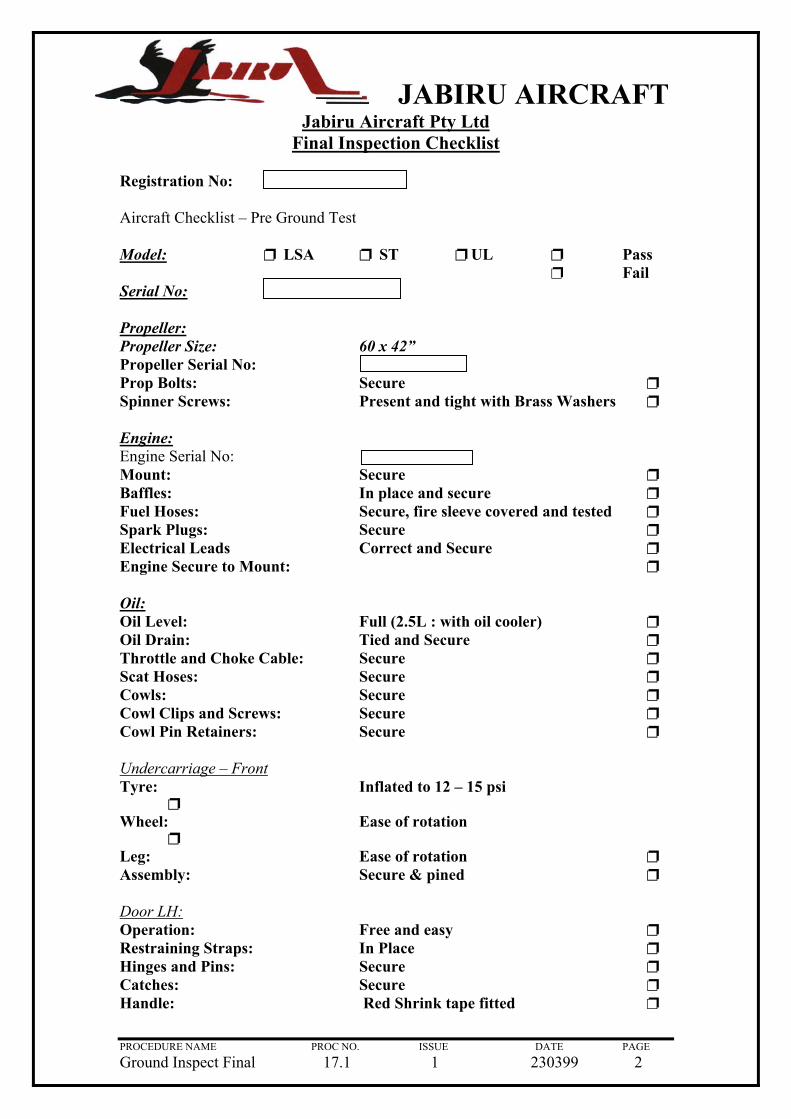
Jabiru Aircraft Pty Ltd Final Inspection Checklist
Registration No: Aircraft Checklist – Pr Model: ❐
Serial No: Propeller: Propeller Size: Propeller Serial No: Prop Bolts: Spinner Screws: Engine: Engine Serial No: Mount: Baffles: Fuel Hoses: Spark Plugs: Electrical Leads Engine Secure to Mou Oil: Oil Level: Oil Drain: Throttle and Choke CScat Hoses: Cowls: Cowl Clips and ScrewCowl Pin Retainers: Undercarriage – FrontTyre: ❐ Wheel: ❐ Leg: Assembly: Door LH: Operation: Restraining Straps: Hinges and Pins: Catches: Handle:
PROCEDURE NAME Ground Inspect Final
e Ground Test
LSA ❐ ST ❐ UL ❐ Pass ❐ Fail
60 x 42” S P
S I S S C
nt:
F T
able: S S S
s: S S
I
E
E S
F I S S
PROC NO. 17.1
ecure ❐ resent and tight with Brass Washers ❐
R
ecure ❐ n place and secure ❐ ecure, fire sleeve covered and tested ❐ ecure ❐ orrect and Secure ❐
❐
ull (2.5L : with oil cooler) ❐ ied and Secure ❐ ecure ❐ ecure ❐ ecure ❐ ecure ❐ ecure ❐
nflated to 12 – 15 psi
ase of rotation
ase of rotation ❐ ecure & pined ❐
ree and easy ❐ n Place ❐ ecure ❐ ecure ❐ ed Shrink tape fitted ❐
ISSUE DATE PAGE 1 230399 2

JABIRU AIRCRAFT
Mains LH: Tyres: Inflated to 25 psi ❐ Tyres: Air valve grommet in place ❐ Wheels: Ease of rotation ❐ Alignment: Slope ❐ Camber ❐ Brake Caliper Secure & Adjusted ❐ Wing LH: Mounts: Secure ❐ Struts: Secure ❐ Fairing: Secure ❐ Aileron LH: Hinge: Secure and retainers in place ❐ Cable and Clamp: Secure ❐ Deflections – up 78mm (measured off template) ❐ Deflections – down 47mm (measured off template) ❐ Flap LH: External Push Rod: Secure ❐ Deflection: Stage 1 37mm (measured off template) ❐ Stage 2 115mm (measured off template) ❐ Fuel: Filler & Cap: Secure ❐ Drain: Operation ❐ Drain: Security – tired ❐ Elevator: Hinge: Secure and retainers in place ❐ Cable and Clamp Secure ❐ Deflections – up mm (measured off template) ❐ Deflections – down mm (measured off template) ❐ Trim System: Cable and Clamp Secure ❐ Rod End Secure Secure ❐ Springs not Coil Bound With full Elevator deflections – up ❐
With full Elevator deflections – down ❐
Rudder: Hinge: Secure and retainers in place ❐ Cable and Clamp: Secure ❐ Deflections – Left 75mm ❐ Deflections – Right 75mm ❐
PROCEDURE NAME PROC NO. ISSUE DATE PAGE Ground Inspect Final 17.1 1 230399 3
Offset to RHS 5mm ❐

JABIRU AIRCRAFT
Static Source: Vent: Secure and clear ❐ Cuff: Fitted and correct ❐ Mains RH: Tyres: Inflated to 25 psi ❐ Tyres: Air valve grommet in place ❐ Wheels: Ease of rotation ❐ Alignment: Slope ❐ Camber ❐ Brake Caliper Secure & Adjusted ❐ Wing RH: Struts: Secure ❐ Mounts: Secure ❐ Fairing: Secure ❐ Aileron RH: Hinge: Secure and retainers in place ❐ Cable and Clamp: Secure ❐ Deflections – up 78mm (measured off template) ❐ Deflections – down 47mm (measured off template) ❐ Flap RH: External Push Rod: Secure ❐ Deflection: Stage 1 37mm (measured off template) ❐ Stage 2 115mm (measured off template) ❐ Pitot: Tube: Secure and clear ❐ Test (by blowing across it) Operation ❐ Door RH: Operation: Free and easy ❐ Restraining Straps: In Place ❐ Hinges and Pins: Secure ❐ Catches: Secure ❐ Handle: Red Shrink tape fitted ❐ Interior: Rudder Pedals: Security ❐ Cable and clamp secure ❐ Ease of operation ❐ Lock Nuts Secure
Ball ends not binding with full deflection to
PROCEDURE NAME PROC NO. ISSUE DATE PAGE Ground Inspect Final 17.1 1 230399 4
the Left & Right Hand Side. ❐

JABIRU AIRCRAFT
Nosewheel Centring: Security ❐ Operation ❐ Flap Controls: Security-Pivot bolt/nut pinned ❐ Operation ❐ Push Rod – secure ❐ Centre Stick: Security-Pivot bolt/nut ❐ Aileron cable anchor point and pins ❐ Aileron bell crank ❐ Elevator cable clearance in centre console ❐ Cable and ball joint security ❐ Throttle: Cable secure and correct ❐ Throttle Shaft: Secure ❐ Brakes: Fluid Level: Full ❐ Security: ❐ Ease of Operation: ❐ Handle & Hand Brake Stop: Secure ❐ Fuel Tank: Tank: Secure ❐ Filler Hose: Secure ❐ Breather Hose: Secure ❐ Mounts and Straps: Secure ❐ Fuel Valve Cover: Fitted ❐ Fuel Lines: Fitted ❐ Handle: Red shrink fitted ❐ Trim Control: Corrected, secure and pinned ❐ Trim Control Stops: Correct ❐ Choke Control: Correct and secure ❐ Seatbelts: Secure and operational ❐ Seatbelt Mounts: Secure ❐ Instrument Panel: Instrument Panel Mounts: Secure ❐ Instrument Panel Retainers: In place ❐
PROCEDURE NAME PROC NO. ISSUE DATE PAGE Ground Inspect Final 17.1 1 230399 5

JABIRU AIRCRAFT
Instruments: ASI: Placarded ❐ Altimeter: Fitted ❐ Balance Ball: Fitted (N/A if Turn Co-Ordinater fitted) ❐ Compass: Fitted ❐ Tacho: Fitted ❐ Oil Temperature Gauge: Fitted ❐ Oil Pressure Gauge: Fitted ❐ CHT: Placarded ❐ Hour meter: Reading ❐ Switches: Operational Mag Guard: In Place Fuses: In Place (spares under seat) Upholstery: Fitted and clean Operational Instruments: Artificial Horizon: Fitted Directional Gyro: Fitted Turn Coordinator: Fitted Suction Gauge: Fitted Radio: VHF: Fitted Operating Optional Radio and Avionics: UHF: Fitted Transponder: Fitted Encoder: Fitted External Appearance: Windows: Fitted and clean Free from defects/scratches Secure Placards: Door Open (interior) x 2 In Place Door Open (Exterior) x 2 In Place Fuel Contents In Place Fuel – AVGAS 100 LL In Place 50 L / 65 L Capacity In Place Earth -On Post In Place On Exhaust In Place Baggage: In Place Loading: In Place Flight Manual: In Place
PROCEDURE NAME PROC NO. ISSUE DATE Ground Inspect Final 17.1 1 23039
Warning: In Place
❐ ❐ ❐
❐
❐ ❐ ❐ ❐
❐ ❐
❐ ❐ ❐
❐ ❐ ❐
❐ ❐ ❐ ❐ ❐ ❐ ❐ ❐ ❐ ❐
PAGE 9 6
❐

JABIRU AIRCRAFT
Trim/Brake: In Place ❐ Fuel On/Off: In Place ❐ Do Not Tighten x 4 In Place ❐ Do Not Lean on Doors x 2 In Place ❐ Choke: In Place ❐ Miscellaneous: Fire Proof Plate In Place ❐ Head Sets ❐ AUF Registration Plate In Place (if appl) ❐ Quick Drain Fuel Tester ❐ Flight Manual In Place ❐ GPS Bracket ❐ Pitot Cover ❐ Empty Weight (incl. Oil) Door Locks -Key Lock ❐ -Manual Lock ❐ Position Weight [kg] Left Main Wheel Right Main Wheel Nose Wheel TOTAL Pitot Static Leak test Has been completed IAW CAO 108.56 ➣ __________ Date: Compass: Date compass was swung Deviation Card:
For N 30 60 E 120 150 Steer For S 210 240 W 300 330 Steer
I hereby certify that the compass has been swung in accordance with CAO 108.6 Signed: _____________________ Date: _________________ For Jabiru Aircraft Pty Ltd Certificate of Approval #
PROCEDURE NAME PROC NO. ISSUE DATE PAGE Ground Inspect Final 17.1 1 230399 7

JABIRU AIRCRAFT
N 000 300 E 090 330 S 180 030 W 270 060
120 150 210
240 Cable Operated Control Systems: I hereby certify that I have inspected the cable control systems IAW the compliance paragraphs of AD/GEN/56 Amdt 3 1st Inspection: _______________ Date: ______________ 2nd Inspection: _______________ LAME #: ______________ These inspection comply with the intent of AD/GEN/56 I hereby certify that this aircraft has been inspected in accordance with this checklist and is fit for flight testing. Signed: ________________________ Date: __________________ For Jabiru Aircraft Pty Ltd Certificate of Approval #
PROCEDURE NAME PROC NO. ISSUE DATE PAGE Ground Inspect Final 17.1 1 230399 8
JABIRU AIRCRAFT
Test Flying
Test Flying should only be performed by a pilot who is licensed, rated and experienced on the aircraft type.
In particular, the test pilot should have recently demonstrated an ability to:
♦ Deal with an engine failure at low altitude (200’) after Take Off.
♦ Recover from stalls in level flight and in banked turns
♦ Recover from a spin.
♦ Recover from unusual attitudes (including a spiral dive).
♦ Carry out a flapless landing
♦ Carry out a glide approach and landing
The Australian CASA (formerly CAA) produces a “Flight Test Guide for Certification of CAO 101.28 Category Airplanes”. As part of the approval process, this document is required to be completed.
In countries other than Australia, the amateur builder should seek advice from the appropriate Airworthiness Authority and/or the relevant amateur building association (EAA Chapter or equivalent).
PROCEDURE NAME PROC NO. ISSUE DATE PAGE Test Flying 17.2 1 230399 1
A copy of the Jabiru Aircraft Pty. Ltd. Flight Test Procedures and Report Form are included for your reference.

JABIRU AIRCRAFT
PPRODUCTION FLIGHT TEST REPORT PROCEDURES RODUCTION FLIGHT TEST REPORT PROCEDURES
1. AIRCRAFT IDENTIFICATION 1. AIRCRAFT IDENTIFICATION PPRROODDUUCCTTIIOONN SSEERRIIAALL NNOO:: RREECCOORRDD TTHHEE AAIIRRCCRRAAFFTT PPRROODDUUCCTTIIOONN SSEERRIIAALL NNUUMMBBEERR FFRROOMM TTHHEE AAIIRRCCRRAAFFTT IIDDEENNTTIIFFIICCAATTIIOONN PPLLAATTEE LLOOCCAATTEEDD BBEEHHIINNDD TTHHEE HHIINNGGEE OONN TTHHEE LLEEFFTT HHAANNDD SSIIDDEE DDOOOORR.. RREEGGIISSTTRRAATTIIOONN:: RREECCOORRDD TTHHEE AAIIRRCCRRAAFFTT RREEGGIISSTTRRAATTIIOONN NNUUMMBBEERR FFRROOMM TTHHEE AAIIRRCCRRAAFFTT IIDDEENNTTIIFFIICCAATTIIOONN PPLLAATTEE LLOOCCAATTEEDD BBEEHHIINNDD TTHHEE HHIINNGGEE OONN TTHHEE LLEEFFTT HHAANNDD SSIIDDEE DDOOOORR.. EENNGGIINNEE:: RREECCOORRDD TTHHEE EENNGGIINNEE SSEERRIIAALL NNUUMMBBEERR FFRROOMM TTHHEE EENNGGIINNEE DDAATTAA PPLLAATTEE OONN TTHHEE CCRRAANNKKCCAASSEE.. PPRROOPPEELLLLEERR:: RREECCOORRDD TTHHEE PPRROOPPEELLLLEERR SSEERRIIAALL NNUUMMBBEERR FFRROOMM TTHHEE PPRROOPPEELLLLEERR HHUUBB.. AAIIRRFFRRAAMMEE HHOOUURRSS:: RREECCOORRDD TTHHEE TTOOTTAALL NNUUMMBBEERR OOFF HHOOUURRSS OONN TTHHEE AAIIRRFFRRAAMMEE.. EENNGGIINNEE HHOOUURRSS:: RREECCOORRDD TTHHEE NNUUMMBBEERR OOFF EENNGGIINNEE HHOOUURRSS OONN TTHHEE EENNGGIINNEE.. 2. COMPASS 2. COMPASS CCHHEECCKK TTHHAATT TTHHEE CCOOMMPPAASSSS HHAASS BBEEEENN SSWWUUNNGG AANNDD TTHHAATT TTHHEE CCAALLIIBBRRAATTIIOONN TTAABBLLEE IISS IINN PPLLAACCEE.. CCOOMMPPLLEETTEE TTHHEE CCEERRTTIIFFIICCAATTIIOONN DDEETTAAIILLSS.. 3. CONFORMITY 3. CONFORMITY CCHHEECCKK TTHHAATT TTHHEE FFIINNAALL IINNSSPPEECCTTIIOONN CCHHEECCKKLLIISSTT HHAASS BBEEEENN CCOOMMPPLLEETTEEDD AANNDD CCEERRTTIIFFIIEEDD.. EEQQUUIIPPMMEENNTT CCOORRRREECCTTLLYY IINNSSTTAALLLLEEDD AANNDD FFUUNNCCTTIIOONNIINNGG:: CCHHEECCKK TTHHAATT AALLLL IINNSSTTRRUUMMEENNTTSS,, RRAADDIIOOSS AANNDD AAVVIIOONNIICCSS AARREE IINNSSTTAALLLLEEDD AANNDD TTHHEE IINNSSTTRRUUMMEENNTTSS,, RRAADDIIOOSS AANNDD AAVVIIOONNIICCSS CCHHEECCKKLLIISSTT HHAASS BBEEEENN CCOOMMPPLLEETTEEDD AANNDD CCEERRTTIIFFIIEEDD.. CCOONNTTRROOLL RRAANNGGEESS:: CCHHEECCKK TTHHAATT AALLLL CCOONNTTRROOLLSS HHAAVVEE FFUULLLL AANNDD FFRREEEE MMOOVVEEMMEENNTT WWIITTHH TTHHEE CCOONNTTRROOLL MMOOVVIINNGG FFUULLLLYY TTOO TTHHEE SSTTOOPP.. CCOONNTTRROOLL MMAARRKKIINNGGSS:: CCHHEECCKK TTHHAATT AALLLL OOFF TTHHEE SSEECCOONNDDAARRYY CCOONNTTRROOLLSS AARREE LLAABBEELLLLEEDD.. IINNSSTTRRUUMMEENNTT RRAANNGGEE MMAARRKKIINNGGSS:: CCHHEECCKK TTHHAATT TTHHEE IINNSSTTRRUUMMEENNTT RRAANNGGEESS AARREE SSHHOOWWNN OORR LLAABBEELLLLEEDD..
PROCEDURE NAME PROC NO. ISSUE DATE PAGE Test Flying 17.2 1 230399 2

JABIRU AIRCRAFT
HHAARRNNEESSSSEESS:: CCHHEECCKK TTHHAATT TTHHEE HHAARRNNEESSSS AARREE PPRREESSEENNTT,, OONN TTHHEE CCOORRRREECCTT SSIIDDEE,, AADDJJUUSSTTAABBLLEE,, AANNDD RREELLEEAASSEE BBUUCCKKLLYY WWOORRKKIINNGG.. DDOOOORRSS:: CCHHEECCKK TTHHEE DDOOOORR OOPPEERRAATTIIOONN AANNDD TTHHAATT TTHHEE LLAATTCCHHEESS AARREE WWOORRKKIINNGG.. 4. ENGINE RUN 4. ENGINE RUN LLOOCCAATTEE TTHHEE AAIIRRCCRRAAFFTT OONN AA WWEELLLL GGRRAASSSSEEDD AARREEAA,, PPOOIINNTT IINNTTOO TTHHEE WWIINNDD AANNDD CCHHOOCCKK TTHHEE WWHHEEEELLSS.. TTUURRNN TTHHEE FFUUEELL TTAAPP OONN,, TTHHEE MMAASSTTEERR SSWWIITTCCHH OONN,, PPUULLLL TTHHEE CCHHOOKKEE OONN AANNDD TTUURRNN TTHHEE IIGGNNIITTIIOONN SSWWIITTCCHH OONN.. DDOO NNOOTT WWEEAARR HHEEAADDSSEETTSS FFOORR TTHHIISS TTEESSTT.. AAUUXXIILLIIAARRYY FFUUEELL PPUUMMPP FFUUNNCCTTIIOONNIINNGG:: TTUURRNN TTHHEE FFUUEELL PPUUMMPP OONN AANNDD LLIISSTTEENN FFOORR IITTSS OOPPEERRAATTIIOONN.. SSTTAARRTTEERR FFUUNNCCTTIIOONN:: DDEEPPRREESSSS TTHHEE SSTTAARRTTEERR BBUUTTTTOONN,, LLIISSTTEENN FFOORR TTHHEE CCLLIICCKK OOFF TTHHEE SSOOLLEENNOOIIDD,, AANNDD TTHHEE WWIINNDDIINNGG OOFF TTHHEE SSTTAARRTTEERR MMOOTTOORR.. LLIISSTTEENN FFOORR TTHHEE SSOOUUNNDD OOFF TTHHEE SSTTAARRTTEERR MMOOTTOORR DDIISSEENNGGAAGGIINNGG.. EENNGGIINNEE OOIILL PPRREESSSSUURREE AAFFTTEERR SSTTAARRTTIINNGG:: WWAATTCCHH TTHHEE EENNGGIINNEE OOIILL PPRREESSSSUURREE IIFF IITT DDOOEESS NNOOTT RRIISSEE IINN TTHHEE FFIIRRSSTT 1100 SSEECCOONNDDSS SSHHUUTT TTHHEE EENNGGIINNEE DDOOWWNN AANNDD CCAALLLL TTHHEE MMEECCHHAANNIICC.. TTHHEE OOIILL PPRREESSSSUURREE RRAANNGGEE SSHHOOUULLDD BBEE FFRROOMM 117755 TTOO 550000 KKPPAA.. IIDDLLEE CCOONNDDIITTIIOONN:: TTHHEE IIDDLLEE SSHHOOUULLDD BBEE SSMMOOOOTTHH AANNDD UUPP TTOO 11440000 RRPPMM,, WWIITTHH TTHHEE CCHHOOKKEE OONN,, AANNDD UUPP TTOO 11110000 RRPPMM WWIITTHHOOUUTT TTHHEE CCHHOOKKEE.. CCHHEECCKK TTHHEE OOIILL TTEEMMPPEERRAATTUURREE,, IITT SSHHOOUULLDD RRIISSEE SSLLOOWWLLYY AANNDD SSTTEEAADDIILLYY TTOO 4488 –– 6600 °°CC,, AANNDD TTHHEE CCYYLLIINNDDEERR HHEEAADD TTEEMMPPEERRAATTUURREE SSHHOOUULLDD RRIISSEE TTOO 8855 –– 110055 °°CC.. TTHHEE EEXXHHAAUUSSTT TTEEMMPPEERRAATTUURREE GGAAUUGGEE ((IIFF FFIITTTTEEDD)) SSHHOOUULLDD RREEAADD BBEETTWWEEEENN 442255 –– 448855 °°CC.. TTUURRNN TTHHEE AAUUXXIILLIIAARRYY FFUUEELL PPUUMMPP OOFFFF.. OONNCCEE TTHHEE EENNGGIINNEE HHAASS WWAARRMMEEDD ((EEOOTT 5500°°CC)) PPRROOCCEEEEDD,, IIFF TTHHEERREE IISS AANNYY DDOOUUBBTT RREEGGAARRDDIINNGG TTHHEE IIDDLLEE FFIIGGUURREESS DDOO NNOOTT PPRROOCCEEEEDD.. IIGGNNIITTIIOONN DDRROOPP AATT 22000000 RRPPMM:: IINNCCRREEAASSEE TTHHEE EENNGGIINNEE SSPPEEEEDD TTOO 22000000 RRPPMM AANNDD CCHHEECCKK TTHHEE IIGGNNIITTIIOONNSS IINNDDIIVVIIDDUUAALLLLYY.. IIFF AA RRPPMM DDRROOPP OOFF MMOORREE TTHHAANN 220000 RRPPMM OOCCCCUURRSS SSHHUUTTDDOOWWNN TTHHEE EENNGGIINNEE AANNDD CCAALLLL TTHHEE MMEECCHHAANNIICC.. MMAAXXIIMMUUMM PPOOWWEERR ((NNOOTT MMOORREE AANNDD 22 MMIINNSS ::)) OOPPEENN TTHHEE TTHHRROOTTTTLLEE SSLLOOWWLLYY UUNNTTIILL IITT IISS FFUULLLLYY OOPPEENN,, TTHHEE EENNGGIINNEE SSHHOOUULLDD NNOOTT FFAALLTTEERR OORR SSUURRGGEE DDUURRIINNGG TTHHIISS OOPPEERRAATTIIOONN.. RREECCOORRDD TTHHEE MMAAXXIIMMUUMM SSTTAATTIICC SSPPEEEEDD ((22997755 –– 33005500 RRPPMM)) AACCHHIIEEVVEEDD;; WWAAIITT FFOORR 6600 SSEECC AANNDD TTHHEENN RREECCOORRDD TTHHEE OOIILL PPRREESSSSUURREE,, OOIILL TTEEMMPPEERRAATTUURREE,, CCYYLLIINNDDEERR HHEEAADD TTEEMMPPEERRAATTUURREE AANNDD EEXXHHAAUUSSTT GGAASS TTEEMMPPEERRAATTUURREE ((IIFF FFIITTTTEEDD))..
PROCEDURE NAME PROC NO. ISSUE DATE PAGE Test Flying 17.2 1 230399 3

JABIRU AIRCRAFT
CCAARRBBUURREETTTTOORR HHEEAATT FFUUNNCCTTIIOONN:: WWHHIILLEE AATT MMAAXXIIMMUUMM PPOOWWEERR AAPPPPLLYY TTHHEE CCAARRBBYY HHEEAATT,, AA DDRROOPP IINN SSPPEEEEDD SSHHOOUULLDD BBEE NNOOTTIICCEEAABBLLEE ((MMAAXX TTOO 220000 RRPPMM)).. VVHHFF FFUUNNCCTTIIOONNIINNGG ((BBNN 112244. .11)) –– RREEAADDAABBIILLIITTYY:: CCAALLLL BBRRIISSBBAANNEE FFOORR AA RRAADDIIOO CCHHEECCKK TTHHEE RREESSUULLTT SSHHOOUULLDD BBEE RREEAADDAABBIILLIITTYY 44--55.. IIFF NNOOTT,, NNOOTTEE FFOORR TTHHEE RRAADDIIOO TTEECCHHNNIICCIIAANN.. EENNGGIINNEE SSHHUUTTDDOOWWNN:: CCHHEECCKK TTHHEE IIDDLLEE WWIITTHH TTHHEE WWAARRMM EENNGGIINNEE,, IITT SSHHOOUULLDD BBEE SSMMOOOOTTHH 880000 RRPPMM.. TTUURRNN BBOOTTHH OOFF TTHHEE IIGGNNIITTIIOONN OOFFFF AANNDD TTHHEE EENNGGIINNEE SSHHOOUULLDD SSTTOOPP SSMMOOOOTTHHLLYY.. 5. FLIGHT TEST #1 – FUNCATION 5. FLIGHT TEST #1 – FUNCATION LLOOAADDIINNGG:: LLOOAADD TTHHEE AAIIRRCCRRAAFFTT WWIITTHH OONNLLYY OONNEE PPIILLOOTT AANNDD AA MMAAXXIIMMUUMM OOFF 2200 LL OOFF FFUUEELL.. EENNGGIINNEE SSTTAARRTT AANNDD RRUUNN--UUPP:: SSTTAARRTT TTHHEE EENNGGIINNEE NNOORRMMAALLLLYY AANNDD PPEERRFFOORRMM AANN EENNGGIINNEE RRUUNN--UUPP.. TTAAXXII:: TTAAXXII AALLOONNGG TTHHEE NNOORRMMAALL RROOUUTTEE TTOO TTHHEE FFUUEELL DDEEPPOOTT WWIITTHH TTHHEE HHEEAADDSSEETTSS RREEMMOOVVEEDD.. LLIISSTTEENN FFOORR AANNDD NNOOTTEE:: AAIIRRFFRRAAMMEE SSOOUUNNDD FFUUEELL PPUUMMPP FFUUNNCCTTIIOONNIINNGG SSTTRROOBBEE FFLLAASSHHIINNGG ((IIFF FFIITTTTEEDD)) SSUUSSPPEENNSSIIOONN MMOOVVEEMMEENNTT DDOOOORRSS AANNDD WWIINNDDSSCCRREEEENN SSTTRRUUCCTTUURREE MMOOVVEEMMEENNTT WWHHEEEELL BBEEAARRIINNGGSS TTYYRREESS RRUUBBBBIINNGG OONN TTHHEE WWHHEEEELL SSPPAATTSS ((IIFF FFIITTTTEEDD)) EENNDD FFLLOOAATT,, FFRROONNTT SSTTEEEERRIINNGG PPIIVVOOTT CCHHEECCKK AANNDD SSEEEE TTHHEE CCOONNTTRROOLL MMOOVVEEMMEENNTTSS BBRRAAKKEE TTRRAACCKKIINNGG AAPPPPRROOAACCHHIINNGG TTHHEE FFUUEELL DDEEPPOOTT CCUUTT TTHHEE EENNGGIINNEE.. CCHHEECCKK TTHHAATT TTHHEE AAIIRRCCRRAAFFTT RROOLLLLSS FFRREEEELLYY WWIITTHHOOUUTT BBRRAAKKEE DDRRAAGG.. AATT AA SSLLOOWW SSPPEEEEDD WWIITTHHOOUUTT FFEEEETT OONN TTHHEE RRUUDDDDEERR PPEEDDAALLSS AAPPPPLLYY TTHHEE BBRRAAKKEESS FFIIRRMMLLYY,, TTHHEE BBRRAAKKEESS SSHHOOUULLDD PPUULLLL SSTTRRAAIIGGHHTT AANNDD SSTTOOPP AABBRRUUPPTTLLYY.. OONN TTHHEE MMOOVVEEMMEENNTT AARREEAA NNEEAARR TTHHEE TTEERRMMIINNAALL BBUUIILLDDIINNGG CCHHEECCKK TTHHEE TTUURRNNIINNGG CCIIRRCCLLEE ((LLEEFFTT AANNDD RRIIGGHHTT TTUURRNNSS)).. TTHHEE RRAADDIIUUSS OOFF TTHHEE LLEEFFTT AANNDD RRIIGGHHTT TTUURRNNSS SSHHOOUULLDD BBEE TTHHEE SSAAMMEE.. FFAACCEE IINNTTOO AANNDD TTAAXXII IINNTTOO TTHHEE WWIINNDD.. TTHHEE AAIIRRCCRRAAFFTT SSHHOOUULLDD TTRRAACCKK SSTTRRAAIIGGHHTT WWIITTHH FFEEEETT OOFFFF TTHHEE RRUUDDDDEERR PPEEDDAALLSS..
PROCEDURE NAME PROC NO. ISSUE DATE PAGE Test Flying 17.2 1 230399 4

JABIRU AIRCRAFT
PPRREE--TTAAKKEE OOFFFF CCHHEECCKKSS LLIISSTTEENN FFOORR TTRRAAFFFFIICC AANNDD WWHHEERREE PPOOSSSSIIBBLLEE WWAAIITT FFOORR TTRRAAFFFFIICC TTOO CCLLEEAARR FFOORR FFIISSTT FFLLIIGGHHTT.. CCAARRRRYY OOUUTT PPRREE--TTAAKKEE OOFFFF CCHHEECCKKSS AASS PPEERR OOPPEERRAATTIIOONNSS MMAANNUUAALL.. AADDVVIISSEE TTRRAAFFFFIICC TTHHAATT AA FFIIRRSSTT FFLLIIGGHHTT IISS TTOO BBEE CCOONNDDUUCCTTEEDD.. RREECCOORRDD OOAATT,, WWIINNDD VVEELLOOCCIITTYY,, WWIINNDD DDIIRREECCTTIIOONN AANNDD RRUUNNWWAAYY.. CCHHEECCKK CCOONNTTRROOLLSS FFOORR FFUULLLL AANNDD FFRREEEE MMOOVVEEMMEENNTT.. TTAAKKEEOOFFFF:: AAFFTTEERR LLIIFFTT OOFFFF CCHHEECCKK IINNSSTTRRUUMMEENNTTSS AANNDD LLIISSTTEENN,, FFEEEELL AANNDD SSMMEELLLL IIFF IINN DDOOUUBBTT AABBOORRTT.. CCLLIIMMBB TTOO 330000 FFTT RREEDDUUCCEE PPOOWWEERR TTOO 22880000 RRPPMM AANNDD CCRRUUIISSEE CCLLIIMMBB AATT 8800 KKTTSS OOVVEERR TTHHEE AAIIRRPPOORRTT.. MMOONNIITTOORR EENNGGIINNEE GGAAUUGGEESS.. AATT 22000000 FFTT TTRRIIMM FFOORR SSTTRRAAIIGGHHTT AANNDD LLEEVVEELL AATT 22880000 RRPPMM.. SSTTAABBIILLIITTYY AANNDD CCOONNTTRROOLL –– DDIIRREECCTTIIOONNAALL,, LLAATTEERRAALL AANNDD LLOONNGGIITTUUDDIINNAALL:: IIFF TTHHEE RRUUDDDDEERR PPEEDDAALLSS AARREE LLEEVVEELL AANNDD TTHHEE AAIIRRCCRRAAFFTT FFLLIIEESS SSTTRRAAIIGGHHTT WWIITTHH TTHHEE BBAALL IINN TTHHEE CCEENNTTRREE TTHHEE RRIIGGGGIINNGG IISS CCOORRRREECCTT.. IIFF TTHHEE BBAALLLL IISS CCEENNTTRREEDD BBUUTT TTHHEE RRUUDDDDEERR PPEEDDAALLSS AARREE DDIISSPPLLAACCEEDD TTHHEE RRUUDDDDEERR NNEEEEDDSS AADDJJUUSSTTIINNGG.. IIFF TTHHEE BBAALLLL IISS CCEENNTTRREEDD AANNDD TTHHEE RRUUDDDDEERR PPEEDDAALLSS AARREE LLEEVVEELL,, AANNDD TTHHEE AAIIRRCCRRAAFFTT SSTTIILLLL TTUURRNNSS TTHHEENN TTHHEE AAIILLEERROONNSS NNEEEEDD AADDJJUUSSTTMMEENNTT.. AALLLL OOFF TTHHEE CCOORRRREECCTTIIOONNSS RREEQQUUIIRREEDD SSHHOOUULLDD BBEE RREECCOORRDDEEDD IINN TTHHEE CCOOMMMMEENNTTSS SSEECCTTIIOONN AATT TTHHEE EENNDD OOFF TTHHIISS SSEECCTTIIOONN.. LLAANNDDIINNGG:: WWHHEENN LLAANNDDIINNGG CCHHEECCKK TTHHAATT TTHHEE UUNNDDEERRCCAARRRRIIAAGGEE DDOOEESS NNOOTT HHAAVVEE AANNYY UUSSUUAALL NNOOIISSEESS,, TTHHAATT TTHHEE AAIIRRCCRRAAFFTT IISS EEAASSIILLYY CCOONNTTRROOLLLLEEDD AANNDD TTHHAATT TTHHEE BBRRAAKKEESS WWOORRKK.. AAFFTTEERR LLAANNDDIINNGG:: RREEPPOORRTT AALLLL DDEEFFEECCTTSS,, RREECCTTIIFFYY AANNDD RREE--TTEESSTT.. 6. FLIGHT TEST # 2 6. FLIGHT TEST # 2 LLOOAADDIINNGG:: TTHHIISS FFLLIIGGHHTT TTEESSTT IISS PPEERRFFOORRMMEEDD AATT MMTTOOWW.. TTWWOO CCRREEWW AANNDD EENNOOUUGGHH FFUUEELL TTOO BBRRIINNGG TTHHEE WWEEIIGGHHTT TTOO 443300 KKGGSS AANNDD CCAALLCCUULLAATTEE CCGG PPOOSSIITTIIOONN AANNDD CCHHEECCKK LLIIMMIITTSS.. TTIIMMEEDD CCLLIIMMBB -- PPEERRFFOORRMMAANNCCEE:: AATT TTHHEE SSTTAARRTT OOFF TTHHEE CCLLIIMMBB RREECCOORRDD TTHHEE MMEEAANN PPRREESSSSUURREE AALLTTIITTUUDDEE AANNDD TTHHEE OOUUTTSSIIDDEE AAIIRR TTEEMMPPEERRAATTUURREE.. CCLLIIMMBB AATT 6655 KKIIAASS.. FFRROOMM TTHHEE SSTTAARRTT HHEEIIGGHHTT,, RREECCOORRDD TTHHEE TTIIMMEE TTAAKKEENN TTOO CCLLIIMMBB 11000000 FFTT AANNDD TTHHEE IINNDDIICCAATTEEDD RRAATTEE OOFF CCLLIIMMBB.. TTIIMMEEDD CCLLIIMMBB –– EENNGGIINNEE PPAARRAAMMEETTEERRSS:: WWIITTHH TTHHEE EENNGGIINNEE AATT WWIIDDEE OOPPEENN TTHHRROOTTTTLLEE AANNDD TTHHEE AAIIRRCCRRAAFFTT TTRRIIMMMMEEDD TTOO 6655 KKIIAASS RREECCOORRDD TTHHEE EENNGGIINNEE SSPPEEEEDD,, OOIILL PPRREESSSSUURREE,, OOIILL TTEEMMPPEERRAATTUURREE,, CCYYLLIINNDDEERR HHEEAADD TTEEMMPPEERRAATTUURREE AANNDD EEXXHHAAUUSSTT GGAASS TTEEMMPPEERRAATTUURREE ((IIFF FFIITTTTEEDD)).. MMAAXXIIMMUUMM PPOOWWEERR FFLLIIGGHHTT –– PPEERRFFOORRMMAANNCCEE:: RREECCOORRDD TTHHEE MMEEAANN PPRREESSSSUURREE AALLTTIITTUUDDEE,, TTHHEE OOUUTTSSIIDDEE AAIIRR TTEEMMPPEERRAATTUURREE,, TTHHEE MMAAXXIIMMUUMM IIAASS IINN LLEEVVEELL FFLLIIGGHHTT WWIITTHH 33110000 RRPPMM..
PROCEDURE NAME PROC NO. ISSUE DATE PAGE Test Flying 17.2 1 230399 5

JABIRU AIRCRAFT
MMAAXXIIMMUUMM PPOOWWEERR FFLLIIGGHHTT –– EENNGGIINNEE PPAARRAAMMEETTEERRSS:: WWIITTHH TTHHEE EENNGGIINNEE AATT WWIIDDEE OOPPEENN TTHHRROOTTTTLLEE AANNDD TTHHEE AAIIRRCCRRAAFFTT IINN SSTTRRAAIIGGHHTT AANNDD LLEEVVEELL FFLLIIGGHHTT RREECCOORRDD TTHHEE EENNGGIINNEE SSPPEEEEDD ((RRPPMM)),, OOIILL PPRREESSSSUURREE,, OOIILL TTEEMMPPEERRAATTUURREE,, CCYYLLIINNDDEERR HHEEAADD TTEEMMPPEERRAATTUURREE AANNDD EEXXHHAAUUSSTT GGAASS TTEEMMPPEERRAATTUURREE ((IIFF FFIITTTTEEDD)).. TTRRIIMM SSPPEEEEDD RRAANNGGEE ((33110000 RRPPMM)):: IINN TTHHEE CCRRUUIISSEE CCOONNFFIIGGUURRAATTIIOONN RREECCOORRDD TTHHEE TTRRIIMM SSPPEEEEDDSS AACCHHIIEEVVEEDD.. TTRRIIMM SSPPEEEEDD LLIIMMIITTAATTIIOONNSS AARREE 8888--9955 FFOORR TTHHEE FFOORRWWAARRDD TTRRIIMM PPOOSSIITTIIOONN AANNDD 6688--7722 IINN TTHHEE AAFFTT TTRRIIMM PPOOSSIITTIIOONN.. TTRRIIMM SSPPEEEEDD RRAANNGGEE ((IIDDLLEE –– 11330000 TTOO 11550000 RRPPMM :: ))IINN TTHHEE AAPPPPRROOAACCHH CCOONNFFIIGGUURRAATTIIOONN RREECCOORRDD TTHHEE TTRRIIMM SSPPEEEEDDSS AACCHHIIEEVVEEDD.. TTRRIIMM SSPPEEEEDD LLIIMMIITTAATTIIOONNSS AARREE 6688--8800 FFOORR TTHHEE FFOORRWWAARRDD TTRRIIMM PPOOSSIITTIIOONN AANNDD 5533--5588 IINN TTHHEE AAFFTT TTRRIIMM PPOOSSIITTIIOONN.. SSTTAALLLLSS:: TTHHEE SSTTAALLLLSS AARREE PPEERRFFOORRMMEEDD IINN AALLLL CCOONNFFIIGGUURRAATTIIOONNSS AASS PPEERR TTHHEE TTAABBLLEE IINN TTHHEE PPRROODDUUCCTTIIOONN FFLLIIGGHHTT TTEESSTT RREEPPOORRTT.. RREECCOORRDD TTHHEE SSPPEEEEDDSS AATT WWHHIICCHH TTHHEE SSTTAALLLLSS OOCCCCUURR.. IIFF AANNYYTTHHIINNGG OOUUTT OOFF TTHHEE NNOORRMMAALL OOCCCCUURRSS RREECCOORRDD IITT IINN TTHHEE CCOOMMMMEENNTTSS AATT TTHHEE BBOOTTTTOOMM OOFF TTHHEE SSEECCTTIIOONN.. VVNE 111166 KKIIAASS:: NE
AATT VVNE NNOOTTEE TTHHEE AAMMOOUUNNTT OOFF BBUUFFFFEETTIINNGG AANNDD VVIIBBRRAATTIIOONN AASS WWEELLLL AASS TTHHEE CCOONNTTRROOLLLLAABBIILLIITTYY OOFF TTHHEE AAIIRRCCRRAAFFTT..
NE
GGLLIIDDEE @@ 6622 KKIIAASS ((IIDDLLEE PPOOWWEERR :: ))RREEDDUUCCEE TTHHEE PPOOWWEERR TTOO IIDDLLEE AANNDD TTRRIIMM TTHHEE AAIIRRCCRRAAFFTT FFOORR AA 6622 KKTT GGLLIIDDEE.. NNOOTTEE TTHHEE CCOONNTTRROOLLLLAABBIILLIITTYY AANNDD IIFF TTHHEE CCOONNTTRROOLLSS AARREE RRIIGGGGEEDD PPRROOPPEERRLLYY.. LLAANNDDIINNGGSS:: WWHHEENN LLAANNDDIINNGG CCHHEECCKK TTHHAATT TTHHEE UUNNDDEERRCCAARRRRIIAAGGEE DDOOEESS NNOOTT HHAAVVEE AANNYY UUNNUUSSUUAALL NNOOIISSEESS,, TTHHAATT TTHHEE AAIIRRCCRRAAFFTT IISS EEAASSIILLYY CCOONNTTRROOLLLLEEDD AANNDD TTHHAATT TTHHEE BBRRAAKKEESS WWOORRKK.. TTAAXXII:: DDUURRIINNGG TTHHEE TTAAXXII CCHHEECCKK TTHHEE CCOONNTTRROOLLLLAABBIILLIITTYY,, SSTTEEEERRIINNGG AANNDD BBRRAAKKEESS.. EENNGGIINNEE SSHHUUTTDDOOWWNN:: TTHHEE EENNGGIINNEE SSHHOOUULLDD SSTTOOPP SSMMOOOOTTHHLLYY WWIITTHHOOUUTT BBAACCKK FFIIRREE EETTCC.. 7. POST FLIGHT 7. POST FLIGHT FFUUEELL UUSSEEDD:: RREECCOORRDD TTHHEE FFUUEELL UUSSEEDD IINN LLIITTRREESS AANNDD CCAALLCCUULLAATTEE TTHHEE WWEEIIGGHHTT OOFF TTHHEE FFUUEELL IINN KKIILLOOGGRRAAMMSS.. CCLLIIMMBB PPEERRFFOORRMMAANNCCEE:: DDEEFFIINNEE TTHHEE WWEEIIGGHHTT AANNDD CCAALLCCUULLAATTEE TTHHEE RRAATTEE OOFF CCLLIIMMBB DDUURRIINNGG TTHHEE TTIIMMEEDD CCLLIIMMBB..
PROCEDURE NAME PROC NO. ISSUE DATE PAGE Test Flying 17.2 1 230399 6

JABIRU AIRCRAFT
PPRREEDDIICCTTEEDD PPEERRFFOORRMMAANNCCEE:: CCOOMMPPAARREE TTHHEE RRAATTEE OOFF CCLLIIMMBB WWIITTHH TTHHEE RRAATTEE OOFF CCLLIIMMBB LLIISSTTEEDD OONN TTHHEE TTYYPPEE CCEERRTTIIFFIICCAATTIIOONN DDAATTAA SSHHEEEETT.. TTHHEE LLIIMMIITTSS FFOORR CCLLIIMMBB PPEERRFFOORRMMAANNCCEE AARREE 442255 TTOO 554455 FFPPMM.. RREESSUULLTTSS ((CCOOMMMMEENNTT OONN TTHHEE FFOOLLLLOOWWIINNGG :: )) EENNGGIINNEE OOPPEERRAATTIIOONN TTHHRROOUUGGHHOOUUTT AAVVIIOONNIICCSS AANNDD SSYYSSTTEEMMSS OOPPEERRAATTIIOONN FFLLIIGGHHTT PPEERRFFOORRMMAANNCCEE CCOONNTTRROOLLLLAABBIILLIITTYY CCOONNTTRROOLL RRIIGGGGIINNGG SSTTAABBIILLIITTYY TTRRIIMM AANNDD HHAANNDDLLIINNGG CCHHAARRAACCTTEERRIISSTTIICCSS 8. RECORD OF AIRCRAFT TIME IN SERVICE 8. RECORD OF AIRCRAFT TIME IN SERVICE FFLLIIGGHHTT NNOO:: DDAATTEE TTIIMMEE IINN SSEERRVVIICCEE 9. RECORD OF AIRCRAFT DEFECT 9. RECORD OF AIRCRAFT DEFECT DDAATTEE DDEEFFEECCTT CCOORRRREECCTTEEDD BBYY 10. CERTIFICATION 10. CERTIFICATION II HHEERREEBBYY CCEERRTTIIFFYY TTHHAATT TTHHIISS AAIIRRCCRRAAFFTT CCOOMMPPLLIIEESS WWIITTHH TTHHEE CCEERRTTIIFFIICCAATTIIOONN
FFLLIIGGHHTT TTEESSTT DDAATTAA AANNDD IISS FFIITT FFOORR SSAALLEE.. SSIIGGNNEEDD:: DDAATTEE::
PROCEDURE NAME PROC NO. ISSUE DATE PAGE Test Flying 17.2 1 230399 7
JJAABBIIRRUU AAIIRRCCRRAAFFTT PPTTYY LLTTDD

JABIRU AIRCRAFT
JABIRU AIRCRAFT PTY LTD JABIRU AIRCRAFT PTY LTD
Production Flight Test Report For LSA 55/3J and ST3 Models Production Serial No. Aircraft Serial No.
Production Serial No. Registration Engine Propeller Airframe Hours Engine Hours
Compass SwuDeviation In P 3. Conformity Equipment correctly insControl Ranges Control Markings Instrument Range MarkHarness Doors 4. Engine Run
PROCEDURE NAME Test Flying
Starter Functioning Auxiliary Fuel Pump FuEngine Oil Pressure afte
1. Aircraft Identification
2. Compass
ng lace
talled and functioning
ings
PROC NO. ISSUE DAT17.2 1 230
nctioning r Starting (40-525 kPa)
E PAGE 399 8

JABIRU AIRCRAFT
Idle Condition RPM ( 800-1100 RPM) EOP ( 40-525 kPa) EOT ( <50-60˚C) CHT ( 50-150˚C) EGT ( 450-500˚C) –If Fitted. Ignition Drop at 200 RPM Ign 1 (max 200) Ign 2 (max 200) Max Power RPM ( 2800-3000 RPM) EOP ( 100-525 kPa) EOT ( <50-118˚C) CHT ( 100-200˚C) EGT ( 500-750˚C) Carb. heat ( 50-200 RPM) VHF Functioning - Readability Engine Shutdown Comments: ___________________________________________________________________________________________________________________________________________________________ Signed:________________________ Jabiru Aircraft Pty Ltd
Certificate of Approval #
PROCEDURE NAME PROC NO. Test Flying 17.2
______________________________________________________________________________________________________________________________________________________________________________________________
Date:__________
ISSUE DATE PAGE 1 230399 9

JABIRU AIRCRAFT
First Flight
Registration No: Production Serial No: Date: Time: VD
O Fuel Quantity
Start
RPM T/O ASI PRM S&L ALT IAS CHT OT OP EGT S&L Full Power RPM IAS
Stall S&L Idle Clean Stall S&L Idle Full Flap Suction Voltage Things To Do _______________________________________________________________________________________________________________________________________________________________________________________________________________________________________________________________________________________________________________________________ Time Finished VDO
PROCEDURE NAME PROC NOTest Flying 17.2
ALT
Stalls
______________ ______________ ______________ ______________ ______________ ______________ ______________ ______________ ______________ ______________ ______________
Fue
. ISSUE 1
Incoming and Outgoing _____________________ _____________________ _____________________ _____________________ _____________________ _____________________ _____________________ _____________________ _____________________ _____________________ _____________________
l Quantity Finish
DATE PAGE 230399 10

JABIRU AIRCRAFT
5. Flight Test #1 – Function Loading Basic Equipment Crew 1 only Fuel (max 20L) L Engine Start and Run-up Taxi Brakes (Pull straight, release 0 no drag) Steering (Runs straight – feet off, radius left and right e Pre-Takeoff Checks Pressure Alt (1014 Hpa) OAT Wind Velocity Wind Direction Runway Controls Check Take-off Controllability Control Rigging Engine RPM (2800-3050 RPM) @ 73 KIAS Cruise Configuration
Lateral and Directional Control Rigging Lateral and Directional Stability and Control Longitudinal Control Rigging and Trim Longitudinal Static Stability Flap Functions (2 stages at 70 KIAS) Performance Climb Cruise Descent Landing Comments: __________________________________________________________________________________________________________________________________________________________________ Signed:_________________ Date: ______
PROCEDURE NAME PROC NO. ISSUE DATest Flying 17.2 1 23
Production Test Pilot
qual)
___
_
T0
_________________________________________
_________
E PAGE 399 11

JABIRU AIRCRAFT
6. Flight Test #2 – Performance Loading Calculations CG Position – Empty
Position Arm [mm] Weight [kg] Index [kg.mm] Left Main Wheel Right Main Wheel Nose Wheel Total CG ============================== CG Position – Loaded Position ARM[mm] Weight [kg] Index [kg.mm] Aircraft Empty Pilot Observer Fuel Total 1 Ballast (430 – Total 1) Total CG ================================
Equations 1. Index = Weight x Arm [kg.mm] 2. CG = Σ Indexes
AUW [mm]
PROCEDURE NAME PROC NO. ISSUE DATE PAGE Test Flying 17.2 1 230399 12
Stalls

JABIRU AIRCRAFT
Straight and Level No Flap – Idle Full Flap – Idle (45 – 50 KIAS) (40 – 45 KIAS) 1 kt/sec
Start from 60 kts
Power Setting
Flap Setting Condition KIAS
Idle No Flap Straight 30° Bank to Left 30° Bank to Right 1 Stage Flap Straight 30° Bank to Left 30° Bank to Right 2 Stage Flap Straight 30° Bank to Left
30° Bank to Right Max Power No Flap Straight
30° Bank to Left 30° Bank to Right 1 Stage Flap Straight 30° Bank to Left 30° Bank to Right 2 Stage Flap Straight 30° Bank to Left
30° Bank to Right Trim Speed Range (3050 rpm)
KIAS Clean From to
(68 – 72 KIAS) (88 – 95 KIAS)
Trim Speed Range (Idle – 1300 to 1500 rpm)
KIAS Full Flap From to
(53 – 58 KIAS) (68 – 70 KIAS)
Result
PROCEDURE NAME PROC NO. ISSUE DATE PAGE Test Flying 17.2 1 230399 13

JABIRU AIRCRAFT
Glide @ 62 KIAS (Idle Power) Controllability 1 Control Rigging 1 Engine RPM (1400-1700 RPM) rpm VNE116 KIAS Vibration 1 Buffeting 1 Controllability 1 (2700-2900 rpm) Max Power Level Flight – Performance (3050 rpm) Pressure Alt. (1013 hPa) OAT Level Flt IAS (95-99 KIAS) Max Power Level Flight – Engine Parameters
EOP (100-525 kPa) EOT (50-118°C) CHT (100-200°C) EGT (550-750°C) RPM (2900-3050 rpm) Timed Climb – Performance
Pressure Alt (1013 hPa) OAT Start Height Finish Height Time to Climb 1000 ft Rate of Climb (indicated) Prop RPM on Climb (2800-3050) Timed Climb – Engine Parameters EOP (100-525 k/Pa) EOT (50-118°C) CHT (100-200°C) EGT (550-750 °C)
PROCEDURE NAME PROC NO. ISSUE Test Flying 17.2 1
ft
°C KIASkPa °C
°C
°C rpmft °C
ft ft secs fmp rpmk/Pa
°C°C
°CDATE PAGE 230399 14

JABIRU AIRCRAFT
General Lateral and Directional Control Rigging ❐ Lateral and Directional Stability and Control ❐ Longitudinal Control Rigging and Trim ❐ Longitudinal Static Stability ❐ Landing Undercarriage ❐ Brakes ❐ Control ❐ Taxi Brakes ❐ Steering ❐ Controllability ❐ Engine Shutdown Comments: _______________________________________________________________________________________________________________________________________________________________________________________________________________ Signed:________________________ Date:__________ Production Test Pilot
PROCEDURE NAME PROC NO. ISSUE DATE PAGE Test Flying 17.2 1 230399 15

JABIRU AIRCRAFT
7. Post Flight Fuel Used L x 0.72 kg /L Climb Performance at kg Weight kg Is the climb performance within or exceed the 10% climb gradient band YES/NO * *- if not; climb tests and data reduction must be performed Engine Operation Throughout ❐ _______________________________________________________________________________________________________________________________________________________________________________________________________________ Avionics and Systems Operation ❐ ______________________________________________________________________________________________________________________________________________________________________________________________________________ Flight Performance ❐ ______________________________________________________________________________________________________________________________________________________________________________________________________________ Controllability ❐ ______________________________________________________________________________________________________________________________________________________________________________________________________________ Control Rigging ❐ ______________________________________________________________________________________________________________________________________________________________________________________________________________ Stability ❐ ______________________________________________________________________________________________________________________________________________________________________________________________________________ Trim and Handling Characteristics ❐ ______________________________________________________________________________________________________________________________________________________________________________________________________________ Signed: Date:
Production Test Pilot
PROCEDURE NAME PROC NO. ISSUE DATE PAGE Test Flying 17.2 1 230399 16

JABIRU AIRCRAFT
8. Record of Time in Service Flight No: Date: Time in Service 9. Record of Defects Date Defect Corrected By 10. Certification I hereby certify that this aircraft complies with the certification flight test data and is fit for sale. Signed: Date: For Jabiru Aircraft Pty Ltd Certificate of Approval #
PROCEDURE NAME PROC NO. ISSUE DATE PAGE Test Flying 17.2 1 230399 17

JABIRU AIRCRAFT
18. Weight Control
PROCEDURE NAME PROC NO. ISSUE DATE PAGE Weight Control 18.0 2 230399 -