1 physically motivated environmental sound synthesis...
TRANSCRIPT

1
Physically Motivated Environmental Sound
Synthesis for Virtual WorldsDylan Menzies
Abstract
A system is described for simulating environmental sound in interactive virtual worlds, using the
physical state of objects as control parameters. It contains a unified framework for integration with physics
simulation engines, and synthesis algorithms that are tailored to work within the framework. A range of
behaviours can be simulated, including diffuse and non-linear resonators, and loose surfaces. The overall
aim has been to produce a flexible and practical system with intuitive controls that will appeal to sound
design professionals. This could be valuable for computer game design, and in other areas where realistic
environmental audio is required. A review of previous work is included, and discussion of the issues
which influence the overall design of the system.
Index Terms
virtual reality, virtual world, sound synthesis, environmental sound
I. INTRODUCTION
In every day life we experience a range of complex sounds, many of which are generated by our direct
interaction with the environment, or are strongly correlated with visual events. For example, we push a
pen across the table, it slides then falls off the table, hits a teacup and rattles inside. To generate even this
simple example convincingly in an interactive virtual world is challenging. The approach commonly used
is simply to match each physical event to a sound taken from a collection of pre-recorded or generated
sample sounds. Even with plentiful use of memory this approach produces poor results in many cases,
particularly in sections where there is continuous evolution of the sound, because the possible range of
sounds is so great, and our ability to correlate subtle visual cues with sound is acute. Foley producers
D. Menzies is with the Department of Media Technology at De Montfort University, UK e-mail: (see
http://www.cse.dmu.ac.uk/∼dylan).
December 13, 2010 DRAFT

2
have known this for many years. When the audio-visual correlation is good the sense of realness and
immersion can be much better than either audio or visuals alone. Conversely when the audio-visual
correlation is poor this can worsen the experience. In the interactive case where we have the ability to
control the sound objects make, this correlation becomes more critical, as our attention is more acute.
The phrase physically motivated audio is used here as short-hand for the use of the macro physical state
of the virtual world to provide the controlling information for the underlying audio processes. The audio
processes model micro physical behaviour that consist of the audio vibrations, and physical behaviour too
fine to be captured by the macro system. The macro physical interactions that can occur in virtual worlds
can be managed by integration under constraints, for which there exists a large literature and a range of
dedicated physics engine software libraries, both commercial and open-source. These implement a wide
range of techniques, but appear broadly similar to the application developer, with some differences of
interface and data organization.
In the context of virtual environments Procedural sound or generative sound refer to algorithmic
sound synthesis in general. This includes synthesis that is not visually or haptically correlated, but can be
parameterized and coded compactly. Weather sounds for example require constant variation and controls
for selecting the current prevailing conditions. The advantages must be weighed against the quality of the
sound compared with sample based sound. If there is no audio-visual correlation, procedural sound may
not be preferable to sampled sound. In the following we focus on physically motivated sound, where the
advantages of procedural approach are clear.
II. REVIEW
Examples of physically motivated audio can be found in the early computer games, such as Asteroids
in which physically modelled collisions occur between objects moving in zero gravity1. Takala and Hahn
presented a dedicated rendering framework for sound in conjunction with computer animation, including
examples such as multiple impacts on a drum [1]. Van den Doel provided the first detailed sound synthesis
examples driven by a rigid body physics simulation [2] that included continuous contact interactions
as well as impacts. Object resonance is modeled with modal resonators, which had previously been
successfully applied in musical applications simulating struck objects [3]. The parameters for a modal
resonator can be very compact. 0.1 KB is enough to encode 10 modes, whereas 100 KB is required to
1Asteroids is a video arcade game released in 1979 by Atari Inc., conceived by Lyle Rains and programmed and designed by
Ed Logg. We overlook the fact that sound cannot travel in empty space!
December 13, 2010 DRAFT
3
store 1 second of CD quality audio. Also the spectral output of a modal resonator can vary constantly
because the states of the modes are independent. This variation is often subtle, but it reproduces an
important audio signature found in real resonators, which would be very expensive to emulate with
samples. The surface is modeled using a profile that is resampled according to the speed of the contact
relative to the surface, and then filtered to reflect the amount of slippage, which is the relative speed of
the surfaces at the contact. If surfaces are just slipping or scraping there is little or no filtering. If the
surfaces roll over each other, there is no slippage, and the interaction is less energetic. This is reflected
with filtering that attenuates higher frequencies.
This work has opened up avenues for further development and improvement. The original contact model
does not work well with more complex profiles, because at lower speeds micro impact are smoothed
out, while for real surfaces micro impacts generally retain some impact character at lower speeds. More
physically detailed contact models have been developed that include the instantaneous interaction between
resonating components in contact [4]. These can generate very good results for some kinds of interaction,
but are computationally more complex, and prone to instability. Being physically explicit, they are not
easily tailored to fit the behaviour desired by a sound designer. Any framework supporting such contact
models would need to closely couple the resonating objects, which would greatly complicate the design.
It is possible that future physics engines may be sufficiently precise to implicitly execute models such as
these, however given that engine development is mainly driven by graphics this is unlikely in the near
future.
There are many interesting surfaces that are not fixed, such as gravel, crumpled foil, sand, leaves, water.
These would be expensive to model as part of the macro physical simulation, and so simplified models
that provide good audio results are sought. In the case of water, the sound from many individual bubbles
has been synthesized. On its own this approach is not very convincing, and quite expensive [5]. With
a fluid dynamics simulation controlling the bubbles the sound is very realistic but very expensive [6].
Clearly there is a need for an inexpensive approach that is convincing, and can be modified by the sound
designer in a flexible way with reference to recordings. Cook has provided examples of synthesis of
foot fall on loose surfaces, made by analyzing recorded surface sounds to generate parameters for filtered
granular processes [7]. It would be valuable to adapt these kind of techniques to a physics enabled virtual
world.
Modal resonators are very efficient at modelling objects that have a few prominent modes, such as
ceramic and metal blocks and containers. Modes can be fitted readily to recordings of such real objects
being struck, and each mode has intuitive control parameters, amplitude frequency and damping. Modes
December 13, 2010 DRAFT

4
are easily removed or added to simplify or enrich a resonator. Modal resonators are less suitable for
more diffuse resonances that are often encountered, such as wooden furniture or large metal panels. In
addition, many resonators exhibit noticeable non-linear behaviour causing pitch glides, spectral migration,
or internal buzzing or rattling effects, which would add interest and realism. Research in musical synthesis
provides examples that address some of these problems using synthesis methods such as 2D waveguides
[8] and finite elements [9], but at much greater cost. More recently non-linear interaction between modes
has been shown effective for synthesizing environmental sounds, but with significantly higher costs
compared with linear modes [10], [11]. Resonator models are needed that can generate this range of
behaviour with the high efficiency, stability and flexibility required of a virtual world. This may require
some compromise of sound quality, which is acceptable for a virtual world setting, although possibly not
in a musical one.
III. PHYA, A LIBRARY FOR PHYSICALLY MOTIVATED AUDIO
A framework should facilitate the appropriate signal flow between audio processes, and manages
the resources. The user should be protected as far as possible from the internal workings including
communication with the physics engine, and should only have to specify the audio properties of the
objects in the virtual world. The software library Phya [12], [13] 2 has been developed to meet these
requirements, and includes a range of audio processes that address the limitations cited in the last section.
C++ is chosen as the main language for simplifying use with physics engines and applications3. Van den
Doel has also developed a Java framework, JASS [14], which provides useful set of objects for building
audio processes. However it has not addressed the problem of integration with a physics engine, or the
further development of audio processes.
For sound designers who are not programmers it is necessary to provide graphical interfaces that
expose the underlying programming interface in an interactive environment for authoring object audio
descriptions, and a way to import these descriptions into Phya. The more interactive the interface, the
faster the design process becomes. This need has been considered by an associated project called VFoley
[13] in which objects can be manipulated in a virtual world while audio parameters are adjusted.
Before discussing the details we pause to make some general observations. In principle sound in a
virtual environment can be reproduced accurately through detailed physical modelling. Even if this were
2Online materials are accessible from www.cse.dmu.ac.uk/∼dylan3There is now a Java port by Sam Bayless, JPhya hosted at Google Code, created for the Golems Universal Constructor
application http://www.golemgame.com/
December 13, 2010 DRAFT
5
achieved it is not enough for the Foley sound designer, who needs to be able to shape the sound according
to their own imagination and reference sounds: Explicit physical models are often difficult to callibrate
to a desired sound behaviour, although they are controlled directly by physical parameters. The physics
engines used are too coarse to calculate audio directly. The audio behaviour is a property of the overall
system, including the physics engine. In this mixed arrangement the connections and management of
parts actually processing audio signals are as relevant as the audio processing. So the description of the
system is by necessity partly mathematical, and partly relational. 4
Physical principles guide the system design, combined with judgements about what is perceptually
most relevant. This has previously been a successful approach in physical modelling of acoustic systems.
A simple observation can lead to a feature that has a big impact. Evaluating a sound generator objectively
is not straightforward. A generator is a function returning sound histories from input histories, which is
a much more complicated object than a single sound history, a sample. This is what makes modelling
so interesting. Nor is it clear how to generalize features that are important, and it may be that no such
generalization can easily be made. Even if this could be done, would it be all that useful? It wouldn’t
have the same significance, for instance, as objective quality evaluation of mp3 recordings. The sound
designer is often more interested in the freedom to shape the sound how they would like, rather than
exactly matching a real behaviour that may not be quite suitable.
The remainder of the article begins by describing the framework and global processes, and then the
audio processes associated with collision and resonance. Practical aspects are highlighted, and we omit
details such as standard filter forms that can be obtained from the references and standard texts. The
structures are robust, the reader will be able to reproduce the results described without fine tuning. The
source code is also available for reference, and most of the features discussed are implemented, although
some are experimental.
IV. FRAMEWORK
For the developer, the framework should provide a set of concepts that simplify the process of thinking
about and programming audio interactions, without overly restricting their scope. A layered structure
is desirable in which more complex features are accessible, but can be overlooked initially. This can
complicate the internal structure of the framework, but it also means that the process as a whole can be
carefully optimized and ordered without laying those tasks on the user.
4Depending from which disciplinary bias the reader comes, they may complain this is either too descriptive, or too
mathematical!
December 13, 2010 DRAFT

6
Because there are several different physics engines that might be used, all with similar features but
with variations of interface, an additional integration layer is required for each physics engine used with
the main audio library, Phya, as shown in Figure 1. The integration layer includes the update function
for processing the physics engine collisions, and callbacks to process expired collisions.These functions
access lower level functions in Phya that are not normally accessed directly by the application developer.
The audio is generated in a separate thread, which sleeps until a waiting audio block is ready to be sent,
and a new block can be calculated.
Audio thread
Application
PhyaPhya integration Physics Engine
Fig. 1. Components in a Phya application. Arrows point in the direction of function calls.
The normal useage of Phya in an application can be summarized by the following steps:
1) Define audio properties of audio objects. This is the main task for the user.
2) Link physical objects in the physics engine to the audio objects. This can usually be done with
user tags in the physics engine.
3) Initialize Phya. Setup any callbacks, for example if the physics engine supports a destroy contact
call back this can be used by the integration layer. Start the audio thread.
4) In the main simulation loop, update Phya with collision data each physics step. This is a function
call to the integration layer that queries the physics engine and updates the Phya collision state,
which is in turn used by the audio thread to generate audio.
A decision that must be made early on is the kind of signal flows that are supported between objects.
For a real contact the resonators may interact instantaneously, which requires direct signal flow in both
directions between the resonators. It was decided not to support this because it complicates the connective
structure while not greatly improving the audio synthesis possibilities. Signal flows can then all be
vectorized. Performance is improved further by minimizing the use of sample buffers in order to improve
cache hits. Buffers are held in a pool so that the last used buffer can be immediately reused elsewhere, in
contrast to the static buffers commonly employed. This has significant impact in a dynamic environment
where objects are being frequently activated and deactivated.
December 13, 2010 DRAFT

7
A. Core objects
Physical systems are naturally represented by class structures. Phya is based around a core set of classes,
that can specialized and extended. Each sounding object is represented by a Body object, which points
to an associated Surface and Resonator object, see Figure 2. A Surface specifies how a collision will be
generated on that surface. On a given surface, any number of collisions with other body surfaces could
be occurring at any time. Sharing surfaces amounts to sharing surface descriptions. Resonators actually
embody the resonating state, so normally each body has a different resonator. Sharing a resonator between
several audio bodies is a useful way to save computation when the physical world contains several similar
bodies close together.
Collisions are managed by Impact and Contact objects that are dynamically created and deleted as
collisions occur between physical objects, so the minimum resources are used. Impacts are momentary
collisions that might occur for instance when two objects bounce off each other, while contacts are
sustained collisions such as sliding or rolling. Impacts delete themselves when they have finished, while
contacts are managed according to the progression of the physical contact.
contact generator
impact
body1
body2
impact generator
body
surfaceresonator
contact
body1
body2
Fig. 2. Main objects in Phya, with arrows pointing to referenced objects.
The physical contact corresponding to each active audio contact needs to be tracked and used to update
the audio contact with dynamical information. An audio contact should be deleted when the physical
contact ceases.
Each Surface class has associated ContactGenerator and ImpactGenerator classes for generating the
particular surface sound. When a Contact or Impact is created it creates an appropriate Generator for
each surface, which is deleted when it is deleted itself. Pools of Contact, Impact and Generator objects
can be pre-initialized to increase simulation performance.
December 13, 2010 DRAFT

8
vel body1 at contact
vel contact
contact force
normal
vel body2 at contact
Fig. 3. Physical parameters at the contact.
B. Physical collision parameters
The Bullet5 physics library has been adopted for recent integration development with Phya. Integration
is discussed here generally, and with particular reference to Bullet.
When contact occurs a region of intersection of the colliding objects is created. The nature of the region
depends on the geometry of the surfaces, the main cases being vertex-surface, edge-surface, edge-edge
and surface-surface, and related cases using curved primitives, cylinders and spheres. In the edge-edge and
vertex-surface cases the region of intersection is small, and represents the single contact point that would
occur between ideal impenetrable surfaces. In surface-surface case ideal contact is distributed over the
surface, and in the edge-surface case over a line. For audio simulation the variation of contact parameters
over the distributed region should be considered. For instance a block spinning flat on a face may have
zero speed relative to the ground at one corner and a maximum value at the other end. Bullet and other
similar engines track a small group of manifold points that span the contact region, and approximate a
region of uniformly distributed contact force. These points tend to stay at fixed positions for a few frames
then disappear as the contact region shifts and new points appear.
At each contact point there are several physical parameters that are useful for generating collision
sound, see Figure 3. Engines usually provide the total impulse for the simulation frame. For impacts this
can be used directly. For contacts the force is estimated by dividing the impulse by the time between
physics simulation frames. The distinction is more important if the simulation time is adaptive.
For surfaces in sustained contact, the slip speed at a point in a region of contact is |vS1 − vS2 | where
vS is the velocity of a surface S at the point. vS can be calculated precisely from the body kinematics
updated by the physics engine.
vS = ω ∧ (rS − rCM ) + vCM , (1)
5http://www.bulletphysics.com
December 13, 2010 DRAFT

9
the cross product of the body angular velocity with the position vector of the contact relative to the body
centre of mass, plus the velocity of the centre of mass. Velocities generated by the engine generally behave
well, they are smooth enough to control audio processes. It may not be easy to choose a representative
surface point in the region, but the variation in velocities will not be so great to be noticeably unsmooth,
especially given the collision synthesis described later.
Also of interest, but not always necessary, is the contact speed relative to each surface at a point
|vC−vS | where vC is the velocity of the contact point. This quantity tells us how quickly surface features
are being traversed, and is particularly important in cases where zero slip conditions may still result in
surface excitation, for example when rolling. vC is harder to determine than the slip speed, and there are
several possible approaches, with varying degrees of accuracy and smoothness. Contact generators such
as those that use sample playback require high smoothness, while others such as stochastic generators
are much more tolerant.
It is possible to solve geometrically using body kinematics, but in the most general case this is complex,
and only relevant when curved contact primitives are used or fine meshes. For two surfaces both with
spherical curvature at the contact, the contact point is constrained to divide the length between the centers
of curvature in a constant ratio, so the contact velocity is
vC = (|rC − rCv2|vCv1 + |rC − rCv1|vCv2)/|rCv1 − rCv2|, (2)
where rCv is a centre of curvature of a surface, and vCv the velocity at that point, which is found from
the body kinematics. For a surface with spherical curvature on a plane
vC = ω ∧ (rC − rCv) + vCv, (3)
where here ω is the angular velocity of the plane surface body. A general curved surface is represented
at the contact by two orthogonal curvature directions, and two centers of curvature. To solve for the
contact velocity the angular velocity of both bodies are required and the complexity of the calculation is
not justified by the limited range of application.
A simple, but useful smooth approximation to the contact velocity, is to equate it with the centre-of-
mass velocity of the body which has the highest curvature at the contact. This can fail for geometrically
complex scenarios, such as a disk spinning on a surface with a fixed centre of mass.
Another approach is to numerically differentiate the contact position. With a single manifold point this
can work well. If there are several points, a representative contact position can be calculated from an
average of the point positions weighted by contact force or penetration depth.
December 13, 2010 DRAFT
10
If the surfaces are polygonal a differentiated contact position may jump in a way that is not intended
or evident in the graphics displayed. To smooth the calculated velocity it is best to smooth the positional
data before differentiating. This introduces some latency whose effect is masked to some extent by the
dominant low latency contribution of the contact force to the excitation.
C. Detecting and tracking contacts
An impact can be detected when a collision is new and the normal relative velocity at the contact is
above a threshold. It is common for an impact to be immediately followed by a contact, but it is also
possible for impacts to occur without an associate contact and vice versa.
Contact generators may have internal state that must be updated using data from the associated physical
contact. So the matching physical contact must be tracked for each acoustic contact. The simplest way
of ensuring this is to make use of user tags on physical contacts, pointing them to the acoustic contact.
In Bullet user data is available for each manifold points, but these are not fully persistent over the life
of a contact region. The Bullet source can be modified to add a user data member to the persistent
manifold structure that owns the manifold points. A callback function can be added to intercept deleted
contact points. When there are no longer any manifold points the contact region has disappeared, and the
acoustic contact can be deleted. A less efficient alternative that can only handle one contact region for
each body pair, is to form a hash function from body pairs to acoustic contacts. The acoustic contacts
are then retrieved by enumerating the physical contacts, each of which refers to a body pair.
D. Collision signal routing
The signal routing allows sound generated at each surface to feed the resonator of both colliding objects,
as well as adding surface sound directly to the final output. Signal can also be routed between resonators,
to simulate acoustic transmission, as you might find in a compound object of different materials.
E. Sound spatialization
It is preferable to keep spatialization as separated as possible from sound generation, if possible. A
large body of algorithms and software exist for spatializing, and the best approach depends on the context
of the application. Output from Phya is available as a simple mono or stereo mix, or separately from
each body so that external spatialization can be applied.
A source can be given directionality by filtering the mono signal to produce a signal that varies
with direction from the source. This technique is often used in computer games, and can be applied
December 13, 2010 DRAFT

11
as part of the external spatialization process. However it does not capture the full degrees of freedom
available to a source in general. To do this the synthesis process for each body must generate directional
components, which in the most general case can be encoded using spherical multipoles, [15]. For a
simple linear resonator, this is not required. Mono synthesis followed by external filtering can reproduce
directional sound correctly, because at each frequency the directionality is fixed. For sources in general
the directionality at each frequency can vary over time.
When the listener receives room reflections in addition to the direct signal, which is usually the case,
the pattern of reflections depend on the directivity of the source [15]. This effect occurs for both linear
resonators and general sources, however it can be more pronounced for the general case, as the pattern
of reflections is more variable, [16]. This effect provides more compelling justification for implementing
internal directional source synthesis.
res2
gen1
gen2
res1
Fig. 4. Signal routing at one contact
F. Contact damping
The damping of a body resonator is often effectively increased when the surface is in contact with
another surface. This provides a dynamic variation of resonant behaviour that is characteristic of in-
teractions between several objects, and provides useful cues about the state of the system of objects.
Damping is implemented globally by multiplying damping factors from each surface onto each resonator
it is contact with, up to a maximum, prior to updating the output of the resonator. This is a simple model
that ignores many interactions that can occur, but it is effective in linking the audio state of each body
to its environment.
G. Contact hardness
The hardness of a collision depends on the combined hardness of the surfaces. A collision between a
soft object and a hard one produces a soft collision. Like damping, collision hardness provides important
December 13, 2010 DRAFT

12
cues to the relationships between objects. To simulate hardness, the collision framework must process
parameters from both bodies. The details of this are described in the impact section.
H. Limiting
The unpredictable nature of physical environmental sound requires automated level control, both to
ensure it is sufficiently audible and detailed, and also not so loud to dominate other audio sources or to
clip the audio range. In some cases it is desirable to emphasize a sound relative to others, due to the
user’s focus on the corresponding object in the virtual world. In conventional sample based game audio
engines, compression and limiting are already very widely used for these purposes. Physically modeled
and motivated sound increase this need further. Limiting can be applied first to the dynamic control
parameters, force and velocity, that feed the generators. Then each output stream can be limited using a
short look-ahead brick wall limiter, that can guarantee a limit, without artifacts. The duration of a single
audio system processing vector, which is typically 128 samples at 44.1KHz, provides a suitable amount
of look-ahead.
V. SOUND MODELS
A. Impacts
An impact is a collision over a brief period during which there is an exchange of momentum between
the bodies. A clean impact consists of a single pulse, but longer, more complex functions are common.
The dynamics of an impact depend on a combination of the properties of both surfaces. If the surface
elasticity is modeled by linear springs with constants k1, k2, then the combined spring constant is k =
(k−11 + k−1
2 )−1. Taking k to be the lesser value of k1 and k2 is a useful approximation. The impact
displacement follows a simple harmonic motion, which lasts for half a cycle, as shown in Figure 5. By
considering the centre-of-mass frame, the duration of the impact is π√m/k where m is an effective
mass (m−11 + m−1
2 )−1. The duration is independent of impact velocity, and the effective mass can be
approximated by the lesser mass of m1 and m2. If collisions only occur between objects of similar
mass and possibly the ground, then effective mass does not vary much and can be ignored. The impact
displacement amplitude is, A = v√m/k where v is the relative normal contact speed. To give the
sound designer more freedom over the relation between collision parameters and the impact amplitude,
a piecewise linear scheme is used, with an upper limit also providing a primary stage of audio level
limiting.
December 13, 2010 DRAFT

13
constant k/m pulses
displacement
time
pulse shorterbecause k increasesabove threshold
Fig. 5. Displacements from three impacts, one of which is stiff.
B. Stiffness
Real surfaces are often stiff, meaning they can be modelled more accurately by a spring constant that
increases with displacement, causing reduced duration and a brighter excitation, as shown in Figure 5.
As well as adding realism, this provides important natural listener cues, to the excitation level and source
loudness of the object, and also therefore to the object location, by comparison with the apparent loudness
at the listener.
C. Complex impacts
Impacts are often complex rather than simple pulses. This can be due to the complex nature of the
collision surfaces at small scales, or due to high frequency vibrations of the body. Physics engines cannot
follow small scale features efficiently, so to reproduce a similar effect additional processes are required.
One approach adopted is to calculate a grazing time for the duration of the complex impact. When the
physics engine produces a clean impact, the time taken to bounce in and out of a grazing depth d is
d/vn, where vn is the normal velocity, see Figure 6. An acoustic contact activated for this period, in
addition to the main impact, approximates the multiple interactions than can occur during an impact.
Contact models that generate sequences of micro-impacts stochastically are well suited for generating
complex impacts.
Impacts from high frequency vibrations can be approximated by looking for where the distance between
the receding bodies becomes zero. The separation distance consists of a linear increasing part due to the
normal impact velocity, adjusted by the displacements given by the resonator outputs multiplied by a
suitable scale factor.
Another approach is to use recorded samples for the impacts, randomly selecting and mixing them
according to impact strength. Lowpass filtering can be used to further simulate impact stiffness. This is a
common technique, which becomes much more convincing when combined with contact synthesis with
December 13, 2010 DRAFT
14
contact layer
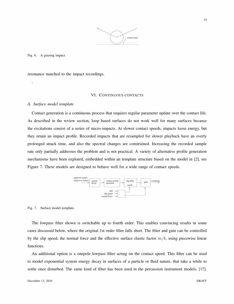
Fig. 6. A grazing impact.
resonance matched to the impact recordings.
.
VI. CONTINUOUS CONTACTS
A. Surface model template
Contact generation is a continuous process that requires regular parameter update over the contact life.
As described in the review section, loop based surfaces do not work well for many surfaces because
the excitations consist of a series of micro-impacts. At slower contact speeds, impacts loose energy, but
they retain an impact profile. Recorded impacts that are resampled for slower playback have an overly
prolonged attack time, and also the spectral changes are constrained. Increasing the recorded sample
rate only partially addresses the problem and is not practical. A variety of alternative profile generation
mechanisms have been explored, embedded within an template structure based on the model in [2], see
Figure 7. These models are designed to behave well for a wide range of contact speeds.
systemrelative to surface excitation
m/kslip speed
normal force
surface profilegeneratordecay
slip filter
cutoff
gain
speed of contact
Fig. 7. Surface model template.
The lowpass filter shown is switchable up to fourth order. This enables convincing results in some
cases discussed below, where the original 1st order filter falls short. The filter and gain can be controlled
by the slip speed, the normal force and the effective surface elastic factor m/k, using piecewise linear
functions.
An additional option is a onepole lowpass filter acting on the contact speed. This filter can be used
to model exponential system energy decay in surfaces of a particle or fluid nature, that take a while to
settle once disturbed. The same kind of filter has been used in the percussion instrument models, [17].
December 13, 2010 DRAFT
15
It can be used with any of the profile generators described below, introducing third dynamic layer, in
addition to the physics engine macro dynamics, and the audio rate micro dynamics.
B. Profile generators
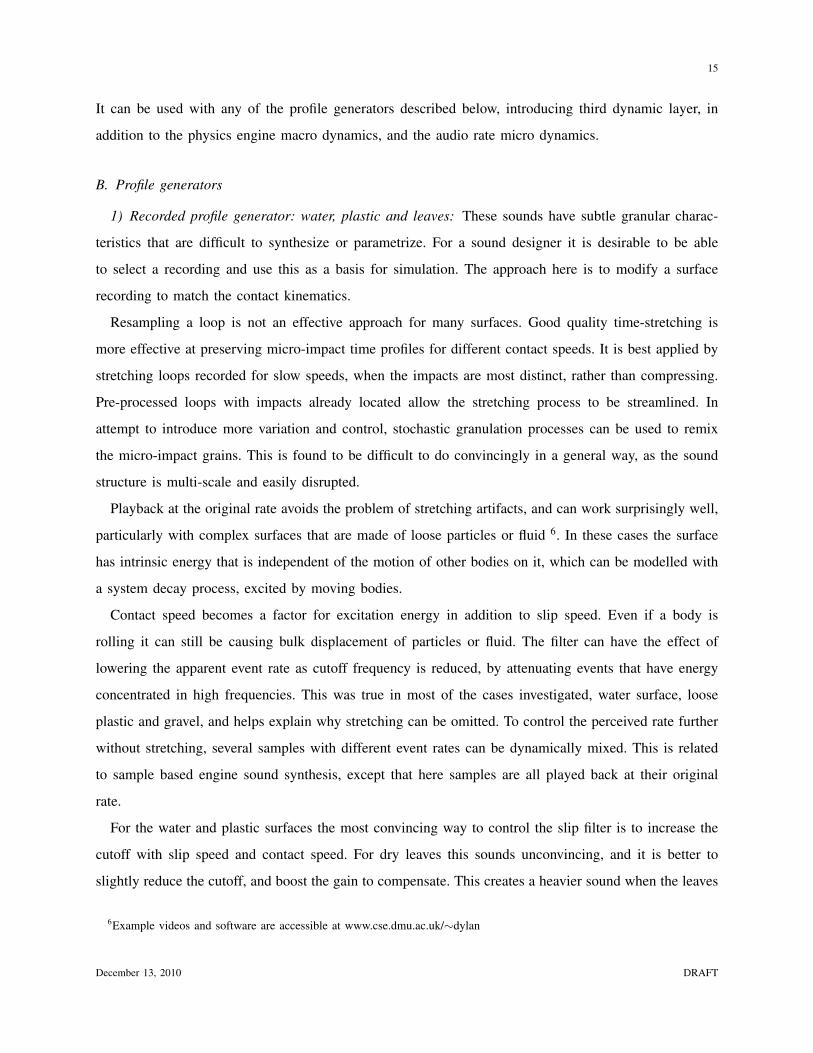
1) Recorded profile generator: water, plastic and leaves: These sounds have subtle granular charac-
teristics that are difficult to synthesize or parametrize. For a sound designer it is desirable to be able
to select a recording and use this as a basis for simulation. The approach here is to modify a surface
recording to match the contact kinematics.
Resampling a loop is not an effective approach for many surfaces. Good quality time-stretching is
more effective at preserving micro-impact time profiles for different contact speeds. It is best applied by
stretching loops recorded for slow speeds, when the impacts are most distinct, rather than compressing.
Pre-processed loops with impacts already located allow the stretching process to be streamlined. In
attempt to introduce more variation and control, stochastic granulation processes can be used to remix
the micro-impact grains. This is found to be difficult to do convincingly in a general way, as the sound
structure is multi-scale and easily disrupted.
Playback at the original rate avoids the problem of stretching artifacts, and can work surprisingly well,
particularly with complex surfaces that are made of loose particles or fluid 6. In these cases the surface
has intrinsic energy that is independent of the motion of other bodies on it, which can be modelled with
a system decay process, excited by moving bodies.
Contact speed becomes a factor for excitation energy in addition to slip speed. Even if a body is
rolling it can still be causing bulk displacement of particles or fluid. The filter can have the effect of
lowering the apparent event rate as cutoff frequency is reduced, by attenuating events that have energy
concentrated in high frequencies. This was true in most of the cases investigated, water surface, loose
plastic and gravel, and helps explain why stretching can be omitted. To control the perceived rate further
without stretching, several samples with different event rates can be dynamically mixed. This is related
to sample based engine sound synthesis, except that here samples are all played back at their original
rate.
For the water and plastic surfaces the most convincing way to control the slip filter is to increase the
cutoff with slip speed and contact speed. For dry leaves this sounds unconvincing, and it is better to
slightly reduce the cutoff, and boost the gain to compensate. This creates a heavier sound when the leaves
6Example videos and software are accessible at www.cse.dmu.ac.uk/∼dylan
December 13, 2010 DRAFT

16
are agitated more. A physical explanation could be that increased agitation causes a greater proportion of
the sound to be generated by leaves that are covered by upper layers. The sound from the lower layers
is muffled by the upper layers. Also the spring-release nature of the leaves mean that the spectral profile
of sound generated by each leaf quickly reaches a limiting state as excitation energy is increased. This
is an example of how a intelligent sound design approach that benefits from physical understanding,
but without detailed modelling. It is found the system decay times must be set precisely to create the
impression of various loose surfaces. This is straightforward to achieve with interactive adjustment.
2) Bump profile generator: fixed granular surfaces: Phya includes some procedural profile models.
The first of these generates a series of bumps of varying width, height and separation. Bump width
control is intended to allow variation of the spectral profile of the micro-collisions, rather than to directly
represent particle width. The width and separation are governed by poisson processes. The poisson rate
parameters are made proportional to the contact speed relative to the surface, so that the bump rate is
also proportional as would be the case for a real surface. Figure 8 shows the an example with poisson
rates for the mark and space.
λ2λ1 λ1
Fig. 8. Bump profile governed by poisson processes.
The bump height can be controlled by an independent random variable, or linked to the bump width.
The less uniform the distribution the greater the impression of different surface particle groupings. The
model is very simple but can produce a range of behaviour from smooth to gritty.
It is sometimes desirable to have a surface that repeats consistently when the contact moves over the
same area. This can be achieved using a procedural approach, such as indexed random variable generators
with the index controlled by position. The main difficulty is in accurately calculating a suitable form
of position variable from the contact parameters. A stored or procedural texture map can also be used.
This can also be applied as a coarse grain parameter structure controlling the fine grained repeating or
non-repeating generators.
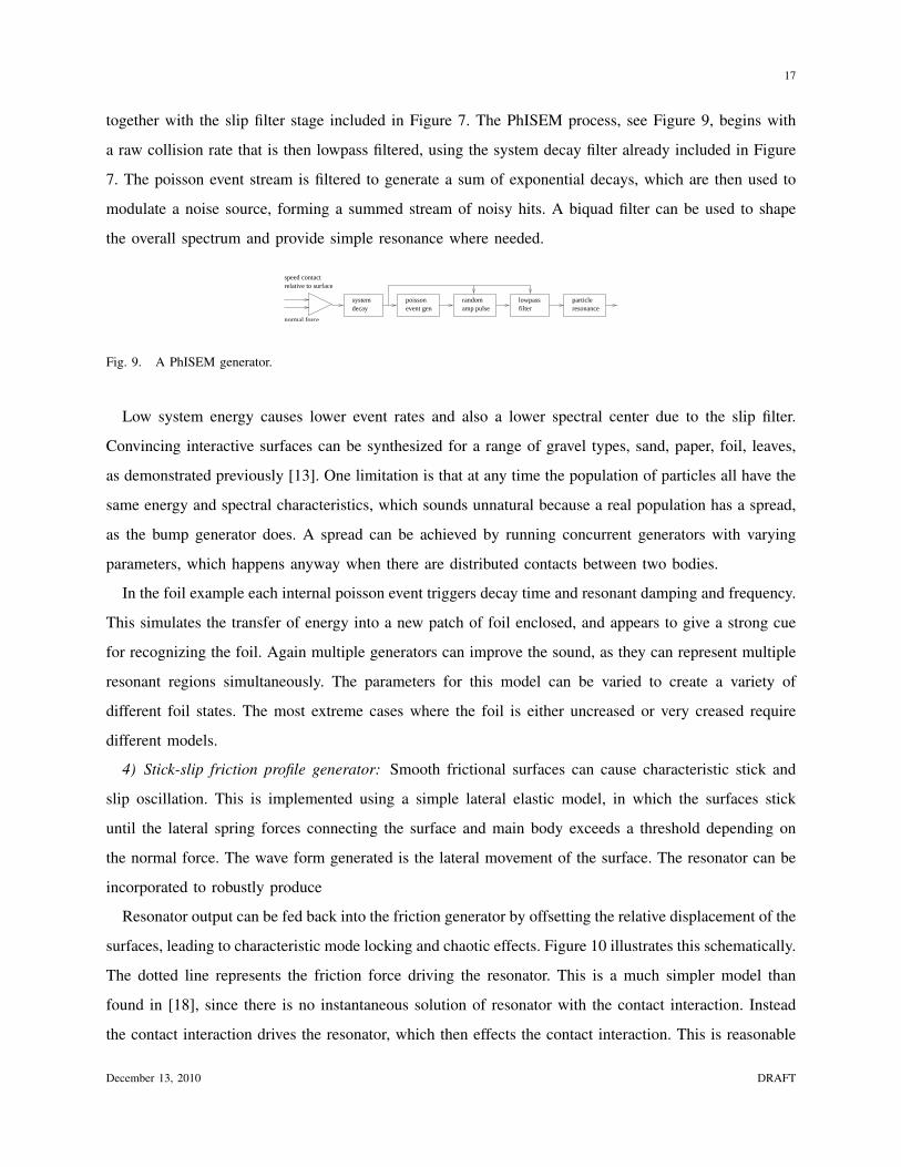
3) Loose particle generator: gravel, foil, sand: Phya contains a related model that is useful for surfaces
where there are many overlapping collisions between loose particles. This uses the PhISEM model, [17]
December 13, 2010 DRAFT
17
together with the slip filter stage included in Figure 7. The PhISEM process, see Figure 9, begins with
a raw collision rate that is then lowpass filtered, using the system decay filter already included in Figure
7. The poisson event stream is filtered to generate a sum of exponential decays, which are then used to
modulate a noise source, forming a summed stream of noisy hits. A biquad filter can be used to shape
the overall spectrum and provide simple resonance where needed.
decaylowpassfilter
speed contactrelative to surface
poissonevent gen
particleresonance
normal force
randomamp pulse
system
Fig. 9. A PhISEM generator.
Low system energy causes lower event rates and also a lower spectral center due to the slip filter.
Convincing interactive surfaces can be synthesized for a range of gravel types, sand, paper, foil, leaves,
as demonstrated previously [13]. One limitation is that at any time the population of particles all have the
same energy and spectral characteristics, which sounds unnatural because a real population has a spread,
as the bump generator does. A spread can be achieved by running concurrent generators with varying
parameters, which happens anyway when there are distributed contacts between two bodies.
In the foil example each internal poisson event triggers decay time and resonant damping and frequency.
This simulates the transfer of energy into a new patch of foil enclosed, and appears to give a strong cue
for recognizing the foil. Again multiple generators can improve the sound, as they can represent multiple
resonant regions simultaneously. The parameters for this model can be varied to create a variety of
different foil states. The most extreme cases where the foil is either uncreased or very creased require
different models.
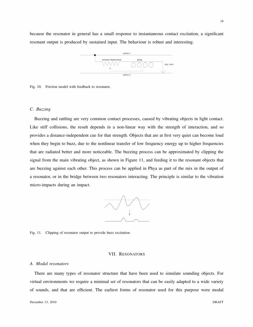
4) Stick-slip friction profile generator: Smooth frictional surfaces can cause characteristic stick and
slip oscillation. This is implemented using a simple lateral elastic model, in which the surfaces stick
until the lateral spring forces connecting the surface and main body exceeds a threshold depending on
the normal force. The wave form generated is the lateral movement of the surface. The resonator can be
incorporated to robustly produce
Resonator output can be fed back into the friction generator by offsetting the relative displacement of the
surfaces, leading to characteristic mode locking and chaotic effects. Figure 10 illustrates this schematically.
The dotted line represents the friction force driving the resonator. This is a much simpler model than
found in [18], since there is no instantaneous solution of resonator with the contact interaction. Instead
the contact interaction drives the resonator, which then effects the contact interaction. This is reasonable
December 13, 2010 DRAFT
18
because the resonator in general has a small response to instantaneous contact excitation, a significant
resonant output is produced by sustained input. The behaviour is robust and interesting.
resonator displacement spring
slip / stick
surface 2
surface 1
Fig. 10. Friction model with feedback to resonator.
C. Buzzing
Buzzing and rattling are very common contact processes, caused by vibrating objects in light contact.
Like stiff collisions, the result depends in a non-linear way with the strength of interaction, and so
provides a distance-independent cue for that strength. Objects that are at first very quiet can become loud
when they begin to buzz, due to the nonlinear transfer of low frequency energy up to higher frequencies
that are radiated better and more noticeable. The buzzing process can be approximated by clipping the
signal from the main vibrating object, as shown in Figure 11, and feeding it to the resonant objects that
are buzzing against each other. This process can be applied in Phya as part of the mix in the output of
a resonator, or in the bridge between two resonators interacting. The principle is similar to the vibration
micro-impacts during an impact.
Fig. 11. Clipping of resonator output to provide buzz excitation.
VII. RESONATORS
A. Modal resonators
There are many types of resonator structure that have been used to simulate sounding objects. For
virtual environments we require a minimal set of resonators that can be easily adapted to a wide variety
of sounds, and that are efficient. The earliest forms of resonator used for this purpose were modal
December 13, 2010 DRAFT

19
resonators [1], [2] which consist of parallel banks of second order resonant filters, each with individual
coupling constants and damping. These are particularly suited to objects with sharp resonances such as
solid objects made from glass, stone and metal. It is possible to identify spectral peaks in the recording
of a such an object, and also the damping by tracking how quickly each peak decays, [19]. A command
line tool is included with Phya for automating this process.
Modal data is psychoacoustically meaningful and can be easily edited to extract, mix or modify modes.
Damping and frequency can be controlled globally. The coupling to each mode varies depending on where
on object is hit. The simplest way to simulate this is with several collision bodies joined together, each
with their own audio body. A more sophisticated and involved approach is to create different coupling
vectors for regions of an object by comparing the modal responses taken from those regions.
B. Diffuse resonance
For a large enough object of a given material the modes become very numerous and merge into a
diffuse continuum. This coincides with the emergence of time domain structure at scales of interest to us,
so that for instance a large plate of metal can be used to create echos and reverberation. For less dense,
more damped material such as wood, noticeable diffuse resonance occurs at modest sizes, for instance
in chairs and doors. Such objects are very common in virtual environments and yet a modal resonator is
not efficiently able to model diffuse resonance, or be matched to a recording. Waveguide methods have
been employed to model diffuse resonance either using abstract networks, including banded waveguides
[20], feedback delay networks [21] or more explicit structures such as waveguide meshes [8], [22]. An
alternative approach introduced in [23], is to mimic a diffuse resonator by dividing the excitation into
frequency bands. The energy in each band is filtered with a onepole filter to model the energy decay of
the diffuse resonance. The resonant energy in each band then modulates a matching synthesized output
noise band. see figure 12. This perceptual resonator provides a diffuse response that responds to the
input spectrum in a perceptually similar way to a linear resonator. Input at a given frequency excites
output at that frequency. When combined with modal synthesis for lower frequencies it can efficiently
simulate wood resonance, and can be easily manipulated by the sound designer. The structure is related
to a vocoder, but with a noise source and band decay filters.
C. Non-linear resonance
The non-linearity of resonators is sometimes clearly audible. For example a gong excited with a soft
mallet radiates a progressively higher proportion of high frequency energy. Cymbals have chaotic crashing
December 13, 2010 DRAFT

20
lowpass
bandpass gain
bandpass gain
noise
+
bandpass envelopefollower
lowpass
bandpass envelopefollower
Fig. 12. Diffuse perceptual resonator model.
sound when hit hard, and in some the pitch glides downwards as the overall amplitude decreases. These
effects can be reproduced by solving directly with finite elements [25], or more efficiently by recasting
in terms of modal interactions [10], [11]. In [10] the output of each mode is fed to a quartic polynomial,
and the sum of these is fed back into each mode. This has O(n) complexity in number of modes. In
[11] more flexibility is provided by allowing each mode to separately drive each other mode, with cost
O(n2). Both cases must be carefully setup to avoid unstable feedback.
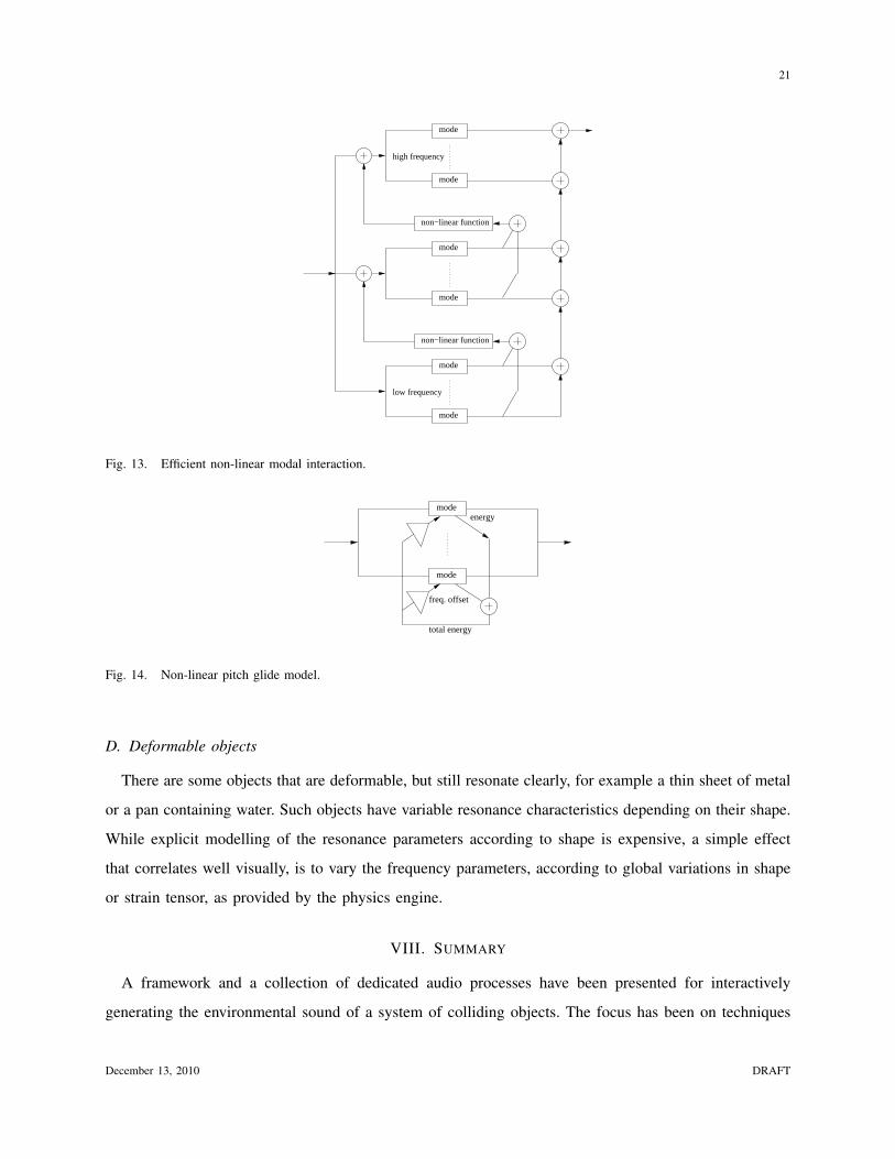
Another structure for non-linear resonance is presented here, see Figure 13. This does not have an
explicit physical basis, however it does have good properties in terms efficiency, stability and intuitive
calibration. The modes are divided into sections that are summed and fed to non-linear functions. The
outputs are fed forward to the next section. Feedback between modes is eliminated. Summing before the
non-linearity rather than after reduces the cost spent on non-linear functions. More importantly, it results
in a denser spectrum in the excitation signal passed to the next section, resulting in better transfer. For
example a quadratic function applied separately to n modes results in at most 2n frequency peaks. If the
function is applied to the sum, there can be as many as n2 peaks.
In the above cases the modal frequencies are all fixed, which prevents the simulation of pitch glides.
Gliding can be simulated by controlling the resonator frequencies with an estimate of the overall resonant
energy, see Figure 14. An instantaneous calculation of the energy is possible by summing the energies
of the individual modes which can be found from their internal state. An increase of energy causes a
reduction in resonant frequency, which is greater for lower frequency modes. The calibration can be made
easily by a sound designer, which is not the case for an explicitly physical approach.
December 13, 2010 DRAFT
21
mode
mode
mode
non−linear function
mode
high frequency
low frequency
mode
non−linear function
mode
Fig. 13. Efficient non-linear modal interaction.
total energy
mode
mode
energy
freq. offset
Fig. 14. Non-linear pitch glide model.
D. Deformable objects
There are some objects that are deformable, but still resonate clearly, for example a thin sheet of metal
or a pan containing water. Such objects have variable resonance characteristics depending on their shape.
While explicit modelling of the resonance parameters according to shape is expensive, a simple effect
that correlates well visually, is to vary the frequency parameters, according to global variations in shape
or strain tensor, as provided by the physics engine.
VIII. SUMMARY
A framework and a collection of dedicated audio processes have been presented for interactively
generating the environmental sound of a system of colliding objects. The focus has been on techniques
December 13, 2010 DRAFT
22
that can be applied realistically with current consumer technology, rather than future technology. This
has involved a mixed bag of approaches, and has been guided both by physical reasoning and critical
listening. Such is the rich variety of natural sound generating processes that it is hard to see how these
could be efficiently simulated by a more uniform approach. The ease with which a sound designer might
calibrate sound objects has been a guiding consideration throughout. Gaining interactivity in sound is
very valuable, but this has to be balanced against loss of authenticity when compared to recorded sound.
It is hoped that the balance will continue swinging towards interactivity.
REFERENCES
[1] J. K. Hahn, H. Fouad, L. Gritz, and J. W. Lee. Integrating sounds and motions in virtual environments. In Sound for
Animation and Virtual Reality, SIGGRAPH 95, 1995.
[2] K. van den Doel, P. G. Kry, and D. K. Pai. Foleyautomatic: Physically-based sound effects for interactive simulation and
animation. In Computer Graphics (ACM SIGGRAPH 01 Conference Proceedings), 2001.
[3] J.M. Adrien. Dynamic modeling of vibrating structures for sound synthesis, modal synthesis. In Proc. Audio Engineering
Socity 7th Int. Conf.: Audio in Digital Times, Toronto, ON, Canada, pages 291–9, 1989.
[4] F. Avanzini, M. Rath, and D Rocchesso. Physically-based audio rendering of contact. In Proc. IEEE Int. Conf. on
Multimedia and Expo, (ICME2002), Lausanne, volume 2, pages 445–448, 2002.
[5] K. van den Doel. Physically-based models for liquid sounds. ACM Transactions on Applied Perception, 2:534–546, 2005.
[6] C. Zheng and D. L. James. Harmonic fluids. ACM Transactions on Graphics, 2009.
[7] P. Cook. Modeling bill’s gait: Analysis and parametric synthesis of walking sounds. In Proceedings of the AES 22nd
International Conference, 2002.
[8] S. A. Van Duyne and J. O. Smith. Physical modeling with the 2-d digital waveguide mesh. In Proc. Int. Computer Music
Conf., Tokyo, 1993.
[9] S. Bilbao. Sound synthesis for nonlinear plates. In Proc. Int. Conf. Digital Audio Effects (DAFx-05), Madrid, September
2005.
[10] S. Petrausch and R. Rabenstein. Tension modulated nonlinear 2d models for digital sound synthesis with the functional
transformation method. In Proc. European Sig. Process. Conf. (EUSIPCO2005), Antalya, Turkey, September 2005.
[11] J.N. Chadwick and D. L. James. Harmonic shells: A practical nonlinear sound model for near-rigid thin shells. In
SIGGRAPH Asia 2009, 2009.
[12] D. Menzies. Scene management for modelled audio objects in interactive worlds. In Proc. International Conference on
auditory Display, 2002.
[13] D. Menzies. Phya and vfoley, physically motivated audio for virtual environments. In Proc. AES 35 International Conference
(London), 2009.
[14] K. van den Doel. Jass: A java audio synthesis system for programmers. In Proc. International Conference on Auditory
Display, 2001.
[15] D. Menzies and M. Al-Akaidi. Ambisonic synthesis of complex sources. Journal of the Audio Engineering Society, 2007.
[16] D. Menzies. Parametric representation of complex parametric representation of complex sources in reflective environments.
In PRoc. AES 128th Convention, May 2010.
December 13, 2010 DRAFT

23
[17] P. Cook. Physically informed sonic modeling (phism): Synthesis of percussive sounds. Computer Music Journal, 21:3,
1997.
[18] F. Avanzini, S. Serafin, and D. Rocchesso. Interactive simulation of rigid body interaction with friction-induced sound
generation. IEEE Tr. Speech and Audio Processing, 13(5.2):1073–1081, 2005.
[19] K. van den Doel. Sound Synthesis for Virtual Reality and Computer Games. PhD thesis, University of British Columbia,
1998.
[20] G. Essl, S. Serafin, P. Cook, and J. Smith. Theory of banded waveguides. Computer Music Journal, spring 2004.
[21] D. Rochesso and J. O. Smith. Circulant and elliptic feedback delay networks for artificial reverberation. IEEE trans.
Speech and Audio, 5(1):1997, 1997.
[22] S. A. Van Duyne and J. O. Smith. The 3d tetrahedral digital waveguide mesh with musical applications. In Proceedings
International Computer Music Conference, 2001.
[23] D. Menzies. Perceptual resonators for interactive worlds. In Proceedings AES 22nd International Conference on Virtual,
Synthetic and Entertainment Audio, 2002.
[24] J. O. Smith and S. A. Van Duyne. Developments for the commuted piano. In Proceedings of the International Computer
Music Conference, Banff, Canada, 1995.
[25] S. Bilbao. Energy-conserving finite difference schemes for tension-modulated strings. In IEEE Int. Conf. on Acoustics
Speech and Signal Processing (Montreal, Canada), number 285-8, 2004.
December 13, 2010 DRAFT