1. overview - maritech · srg-1150dn / srg-1250dn / sn-100 1. overview the peculiarity of gmdss is...
TRANSCRIPT
SRG-1150DN / SRG-1250DN / SN-100
1. OVERVIEW
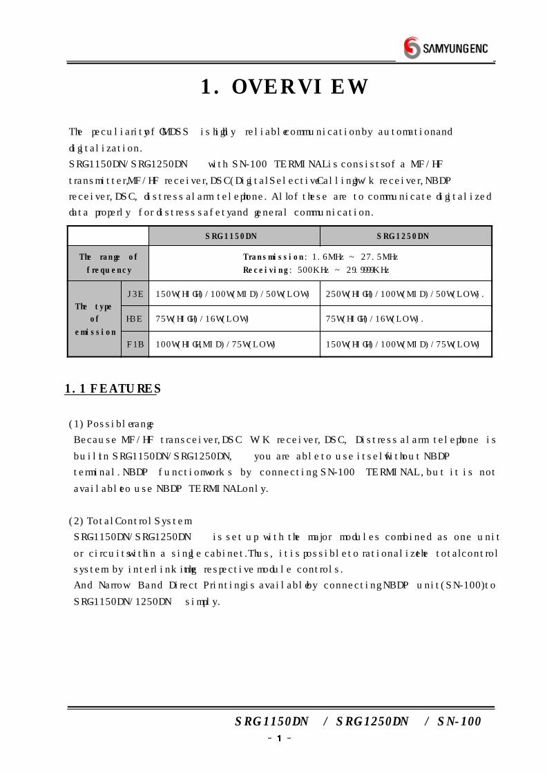
The peculiarity of GMDSS is highly reliable communication by automation and
digitalization.
SRG-1150DN/SRG-1250DN with SN-100 TERMINAL is consists of a MF/HF
transmitter, MF/HF receiver, DSC(Digital Selective Calling) w/k receiver, NBDP
receiver, DSC, distress alarm telephone. All of these are to communicate digitalized
data properly for distress safety and general communication.
SRG-1150DN SRG-1250DN
The range of
frequency
Transmiss ion : 1.6MHz ~ 27.5MHz
Receiving : 500KHz ~ 29.9999KHz
The type
of
emission
J3E 150W(HIGH)/100W(MID)/50W(LOW) 250W(HIGH)/100W(MID)/50W(LOW).
H3E 75W(HIGH)/16W(LOW) 75W(HIGH)/16W(LOW).
F1B 100W(HIGH,MID)/75W(LOW) 150W(HIGH)/100W(MID)/75W(LOW)
1.1 FEATURES
(1) Possible range
Because MF/HF transceiver, DSC W/K receiver, DSC, Distress alarm telephone is
built in SRG-1150DN/SRG-1250DN, you are able to use itself without NBDP
terminal. NBDP function works by connecting SN-100 TERMINAL, but it is not
available to use NBDP TERMINAL only.
(2) Total Control System
SRG-1150DN/SRG-1250DN is set up with the major modules combined as one unit
or circuits within a single cabinet. Thus, it is possible to rationalize the total control
system by interlinking the respective module controls.
And Narrow Band Direct Printing is available by connecting NBDP unit(SN-100) to
SRG-1150DN/1250DN simply.
SRG-1150DN / SRG-1250DN / SN-100
(3) Operability
All general operation such as communication, controls and monitoring, are
performed by SRG-1150DN/SRG-1250DN, NBDP TERMINAL and printer which is
installed in a convenient place.
DSC such as communication, editing messages and viewing received messages are
performed by using the controller. Distress calls can be sent and received by
one-touch operation in an emergency.
And it's easy to write up and Tx/Rx TELEX by using NBDP TERMINAL(SN-100), i t
is easy to figure out contents on a large front display.
(4) Configuration
SRG-1150DN/SRG-1250DN consists of one unit therefore, a large space is not
required for operation. SN-100 TERMINAL is able to use by connecting with
SRG-1150DN/SRG-1250DN cable.
(5) Trustworthy
Adopted new DDS(DIRECT DIGITAL SYNTHESIZE) and improved the quality of
sound, trustworthy, stability.
(6) Construction
In order to endure in bad condition of marine environment, hard aluminum body is
manufactured.
(7) External shape
Channel, frequency, transmitting and receiving conditions can be seen on large LCD
at one sight. And each keys are made by soft rub material, it has stylish shape and
makes you feel comfortable when you press the button. Futhermore there is
frequency sheet for users.
SN-100 NBDP TERMINAL has large, thin, colorful LCD and convenient keyboard.
SRG-1150DN / SRG-1250DN / SN-100
1.2 BASIC COMPONENTS
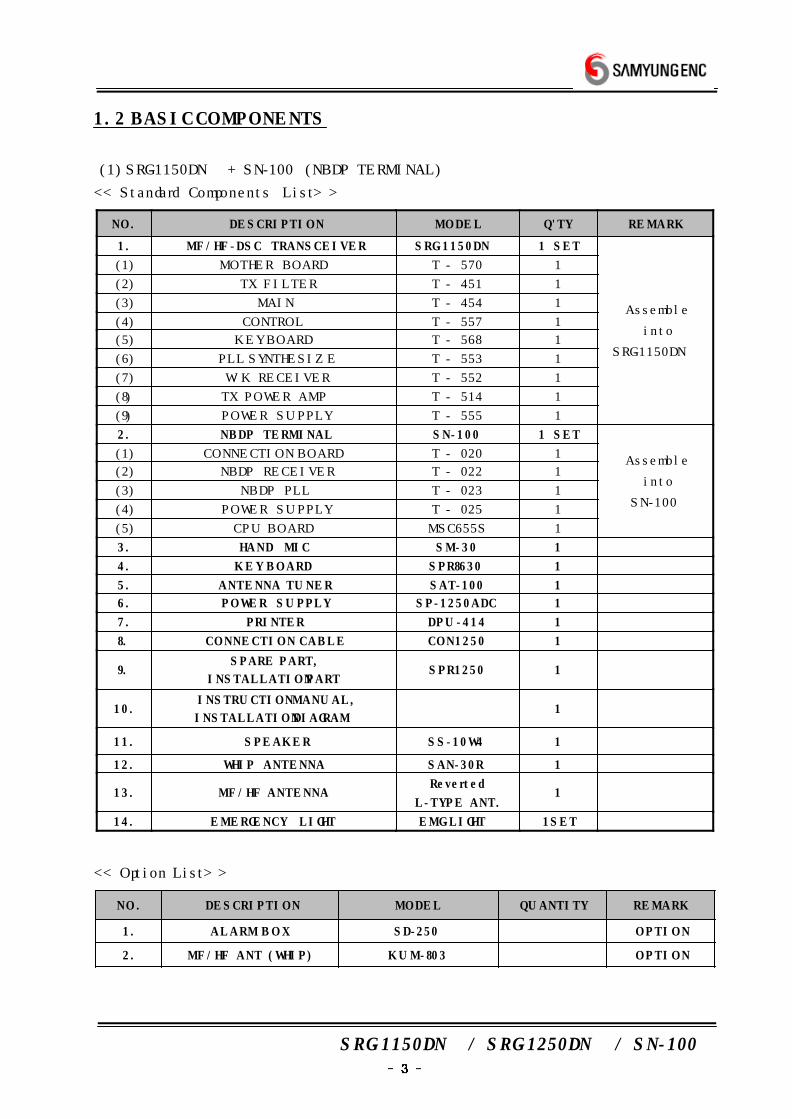
(1) SRG-1150DN + SN-100 (NBDP TERMINAL)
<< Standard Components List >>
NO. DESCRIPTION MODEL Q'TY REMARK
1. MF/HF-DSC TRANSCEIVER SRG-1150DN 1 SET
Assemble
into
SRG-1150DN
(1) MOTHER BOARD T - 570 1
(2) TX FILTER T - 451 1
(3) MAIN T - 454 1
(4) CONTROL T - 557 1
(5) KEY BOARD T - 568 1
(6) PLL SYNTHESIZE T - 553 1
(7) W/K RECEIVER T - 552 1
(8) TX POWER AMP T - 514 1
(9) POWER SUPPLY T - 555 1
2. NBDP TERMINAL SN-100 1 SET
Assemble
into
SN-100
(1) CONNECTION BOARD T - 020 1
(2) NBDP RECEIVER T - 022 1
(3) NBDP PLL T - 023 1
(4) POWER SUPPLY T - 025 1
(5) CPU BOARD MSC655S 1
3. HAND MIC SM-30 1
4. KEY BOARD SPR8630 1
5. ANTENNA TUNER SAT-100 1
6. POWER SUPPLY SP-1250ADC 1
7. PRINTER DPU-414 1
8. CONNECT ION CABLE CON1250 1
9.SPARE PART,
INSTALLATION PARTSPR1250 1
10.INSTRUCTION MANUAL,
INSTALLATION DIAGRAM1
11. SPEAKER SS-10W4 1
12. WHIP ANTENNA SAN-30R 1
13. MF/HF ANTENNAReverted
L-TYPE ANT.1
14. EMERGENCY L IGHT EMG-LIGHT 1SET
<< Option List >>
N O . DESCRIPTION MODEL QUANTITY REMARK
1. ALARM B O X SD-250 OPT ION
2. MF/HF ANT (WHIP) KUM-803 OPT ION
SRG-1150DN / SRG-1250DN / SN-100
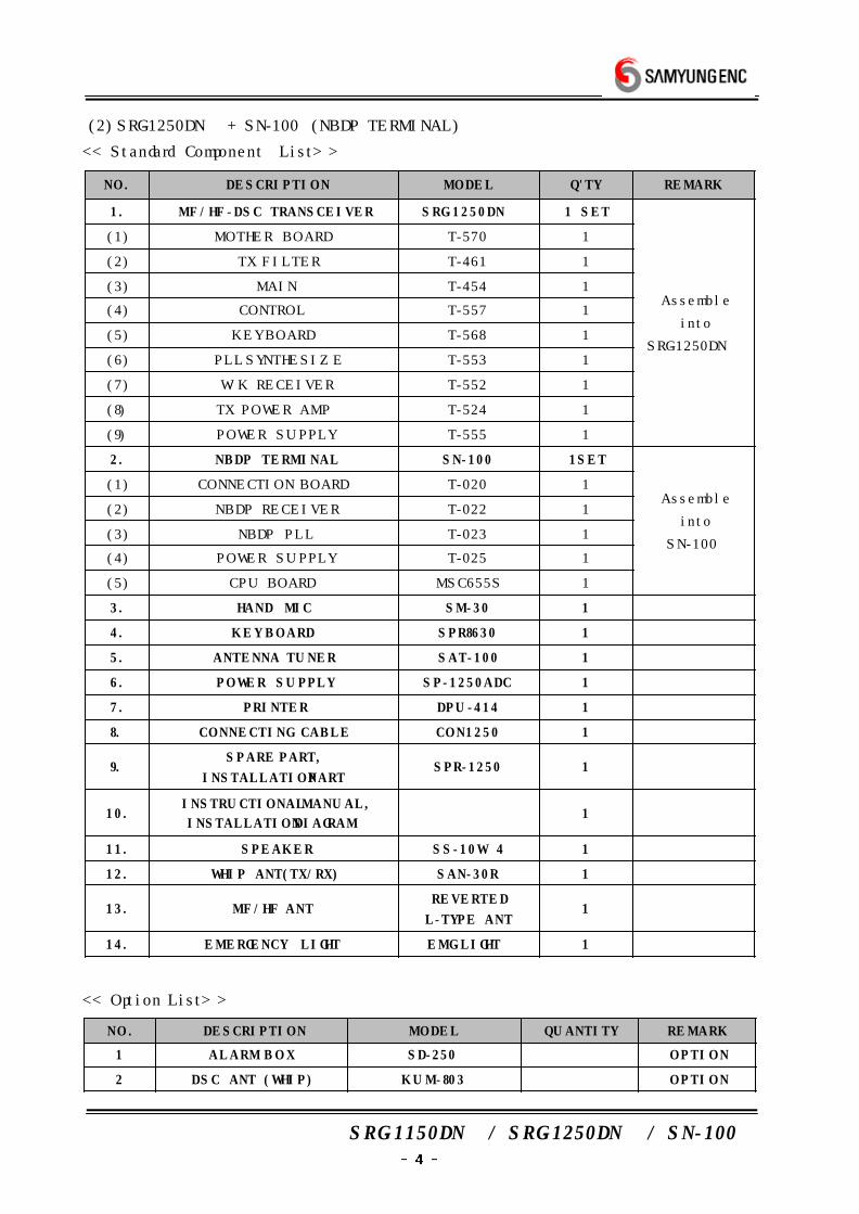
(2) SRG-1250DN + SN-100 (NBDP TERMINAL)
<< Standard Component List >>
NO. DESCRIPT ION MODEL Q'TY REMARK
1. MF/HF-DSC TRANSCEIVER SRG-1250DN 1 SET
Assemble
into
SRG-1250DN
(1) MOTHER BOARD T-570 1
(2) TX FILTER T-461 1
(3) MAIN T-454 1
(4) CONTROL T-557 1
(5) KEY BOARD T-568 1
(6) PLL SYNTHESIZE T-553 1
(7) W/K RECEIVER T-552 1
(8) TX POWER AMP T-524 1
(9) POWER SUPPLY T-555 1
2. NBDP TERMINAL SN-100 1SET
Assemble
into
SN-100
(1) CONNECTION BOARD T-020 1
(2) NBDP RECEIVER T-022 1
(3) NBDP PLL T-023 1
(4) POWER SUPPLY T-025 1
(5) CPU BOARD MSC655S 1
3. HAND MIC SM-30 1
4. KEY BOARD SPR8630 1
5. ANTENNA TUNER SAT-100 1
6. POWER SUPPLY SP-1250ADC 1
7. PRINTER DPU-414 1
8. CONNECT ING CABLE CON1250 1
9.SPARE PART,
INSTALLATION PARTSPR-1250 1
10.INSTRUCTIONAL MANUAL,
INSTALLATION D IAGRAM1
11. SPEAKER SS-10W 4 1
12. WHIP ANT(TX/RX) SAN-30R 1
13. MF/HF ANTREVERTED
L-TYPE ANT1
14. EMERGENCY L IGHT EMG-LIGHT 1
<< Option List >>
N O . DESCRIPTION MODEL QUANTITY REMARK
1 ALARM B O X SD-250 OPT ION
2 DSC ANT (WHIP) KUM-803 OPT ION
SRG-1150DN / SRG-1250DN / SN-100
2. SPECIFICATIONS
2.1 GENERAL SPECIFICATION
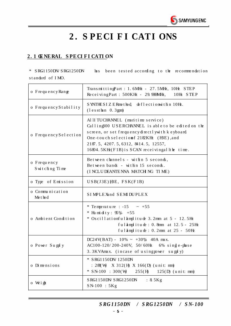
* SRG-1150DN/SRG-1250DN has been tested according to the recommendation
standard of IMO.
o Frequency RangeTransmitting Part : 1.6MHz - 27.5MHz, 10Hz STEP
Receiving Part : 500KHz - 29.9999MHz, 10Hz STEP
o Frequency StabilitySYNTHESIZER method, deflection within 10Hz.
(less than 0.3ppm)
o Frequency Selection
All ITU CHANNEL (maritime service)
Calling 300 USER CHANNEL is able to be edited on the
screen, or set frequency directly with keyboard.
One-touch selection of 2182KHz (H3E),and
2187.5, 4207.5, 6312, 8414.5, 12557,
16804.5KHz(F1B) is SCAN receiving all the time.
o Frequency
Switching Time
Between channels - within 5 seconds,
Between bands - within 15 seconds.
(INCLUDE ANTENNA MATCHING TIME )
o Type of Emission USB(J3E), H3E, FSK(F1B)
o Communication
MethodSIMPLEX and SEMI DUPLEX
o Ambient Condition
* Temperature : -15 ~ +55
* Humidity : 95%, +55
* Oscillation : full amplitude 3.2mm at 5 - 12.5Hz
full amplitude : 0.8mm at 12.5 - 25Hz
full amplitude : 0.2mm at 25 - 50Hz
o Power Supply
DC24V(BAT) - 10% ~ +30%, 40A max.
AC100-120/200-240V, 50/60Hz ±6% single-phase
3.3KVA max. (in case of using power supply)
o Dimensions
* SRG-1150DN/1250DN
: 288(W) X 312(H) X 166(D) (unit : mm)
* SN-100 : 300(W) × 255(H) × 125(D) (unit : mm)
o WeightSRG-1150DN/SRG-1250DN : 8.5Kg
SN-100 : 5Kg
SRG-1150DN / SRG-1250DN / SN-100
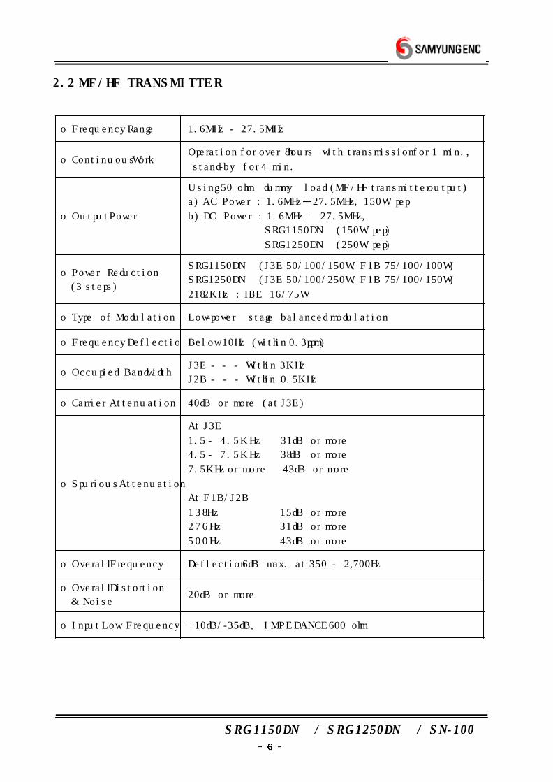
2.2 MF/HF TRANSMITTER
o Frequency Range 1.6MHz - 27.5MHz
o Continuous WorkOperation for over 8hours with transmission for 1 min.,
stand-by for 4 min.
o Output Power
Using 50 ohm dummy load (MF/HF transmitter output)
a) AC Power : 1.6MHz 27.5MHz, 150W pep
b) DC Power : 1.6MHz - 27.5MHz,
SRG-1150DN (150W pep)
SRG-1250DN (250W pep)
o Power Reduction
(3 steps)
SRG-1150DN (J3E 50/100/150W, F1B 75/100/100W)
SRG-1250DN (J3E 50/100/250W, F1B 75/100/150W)
2182KHz : H3E 16/75W
o Type of Modulation Low-power stage balanced modulation
o Frequency Deflection Below 10Hz (within 0.3ppm)
o Occupied BandwidthJ3E - - - Within 3KHz
J2B - - - Within 0.5KHz
o Carrier Attenuation 40dB or more (at J3E)
o Spurious Attenuation
At J3E
1.5 - 4.5KHz 31dB or more
4.5 - 7.5KHz 38dB or more
7.5KHz or more 43dB or more
At F1B/J2B
138Hz 15dB or more
276Hz 31dB or more
500Hz 43dB or more
o Overall Frequency Deflection 6dB max. at 350 - 2,700Hz
o Overall Distortion
& Noise20dB or more
o Input Low Frequency +10dB/-35dB, IMPEDANCE 600 ohm
SRG-1150DN / SRG-1250DN / SN-100
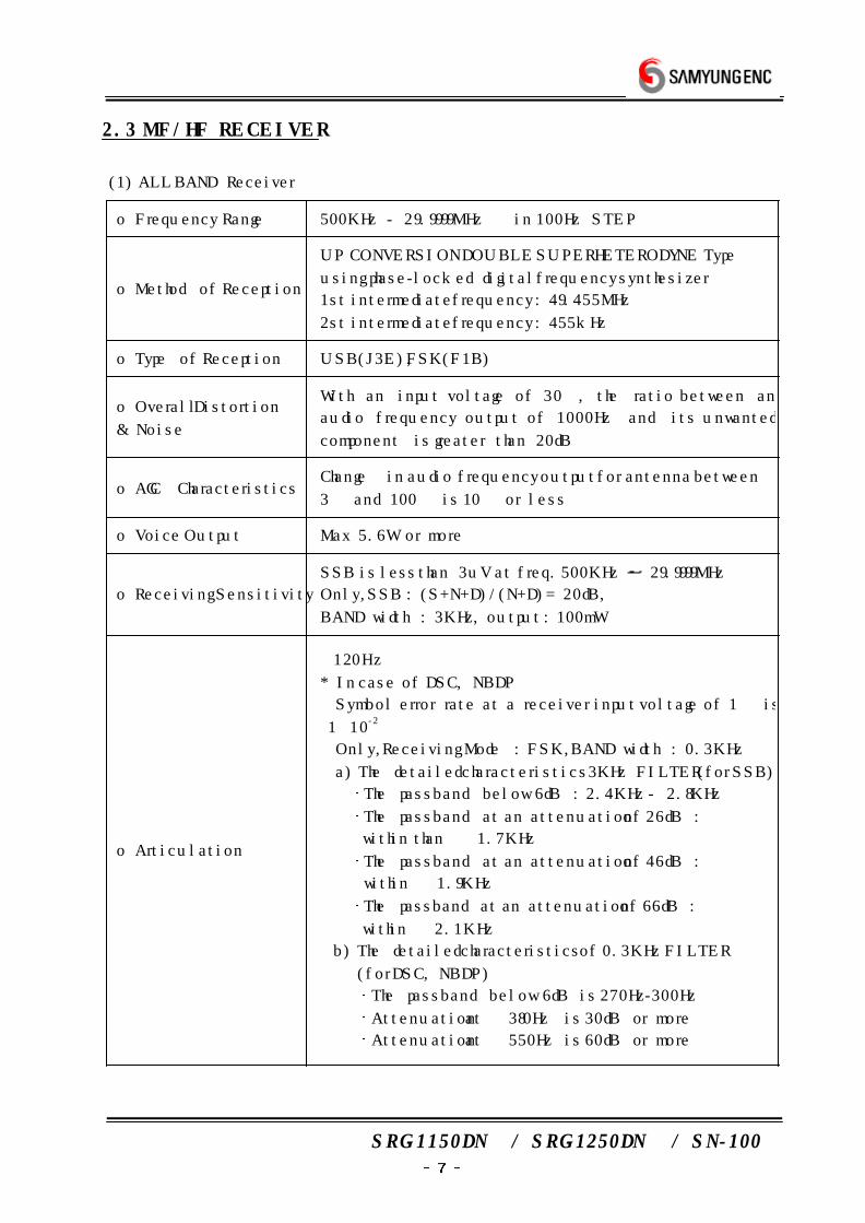
2.3 MF/HF RECEIVER
(1) ALL BAND Receiver
o Frequency Range 500KHz - 29.9999MHz in 100Hz STEP
o Method of Reception
UP CONVERSION DOUBLE SUPERHETERODYNE Type
using phase-locked digital frequency synthesizer
1st intermediate frequency : 49.455MHz
2st intermediate frequency : 455kHz
o Type of Reception USB(J3E), FSK(F1B)
o Overall Distortion
& Noise
With an input voltage of 30, the ratio between an
audio frequency output of 1000Hz and its unwanted
component is greater than 20dB
o AGC CharacteristicsChange in audio frequency output for antenna between
3 and 100 is 10 or less
o Voice Output Max 5.6W or more
o Receiving Sensitivity
SSB is less than 3uV at freq. 500KHz 29.9999MHz
Only, SSB : (S+N+D)/(N+D) = 20dB,
BAND width : 3KHz, output : 100mW
o Articulation
±120Hz
* In case of DSC, NBDP
Symbol error rate at a receiver input voltage of 1 is
1×10⁻²
Only, Receiving Mode : FSK, BAND width : 0.3KHz
a) The detailed characteristics 3KHz FILTER (for SSB)
The passband below 6dB : 2.4KHz - 2.8KHz
The passband at an attenuation of 26dB :
within than ± 1.7KHz
The passband at an attenuation of 46dB :
within ± 1.9KHz
The passband at an attenuation of 66dB :
within ± 2.1KHz
b) The detailed characteristics of 0.3KHz FILTER
(for DSC, NBDP)
The passband below 6dB is 270Hz-300Hz
Attenuation at ± 380Hz is 30dB or more
Attenuation at ± 550Hz is 60dB or more
SRG-1150DN / SRG-1250DN / SN-100
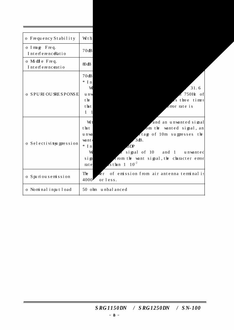
o Frequency Stability Within ±10Hz
o Image Freq.
Interference Ratio70dB or more
o Middle Freq.
Interference ratio80dB or more
o SPURIOUS RESPONSE
70dB or more
* In case of DSC, NBDP
When a wanted signal of 10 and an 31.6
unwanted signal (excluding the range within 750Hz of
the wanted signal) whose range of IF is three times
that of the wanted signal, the symbol error rate is
1×10⁻² or less.
o Selectivity suppression
With a wanted signal of 10 and an unwanted signal
that is effect than 3KHz from the wanted signal, an
unwanted signal input voltage of 10m suppresses the
wanted signal output to 3dB.
* In case of DSC, NBDP
With a wanted signal of 10 and 1 unwanted
signal 500Hz from the want signal, the character error
rate is less than 1×10⁻²
o Spurious emissionThe power of emission from air antenna terminal is
4000 or less.
o Nominal input load 50 ohm unbalanced
SRG-1150DN / SRG-1250DN / SN-100
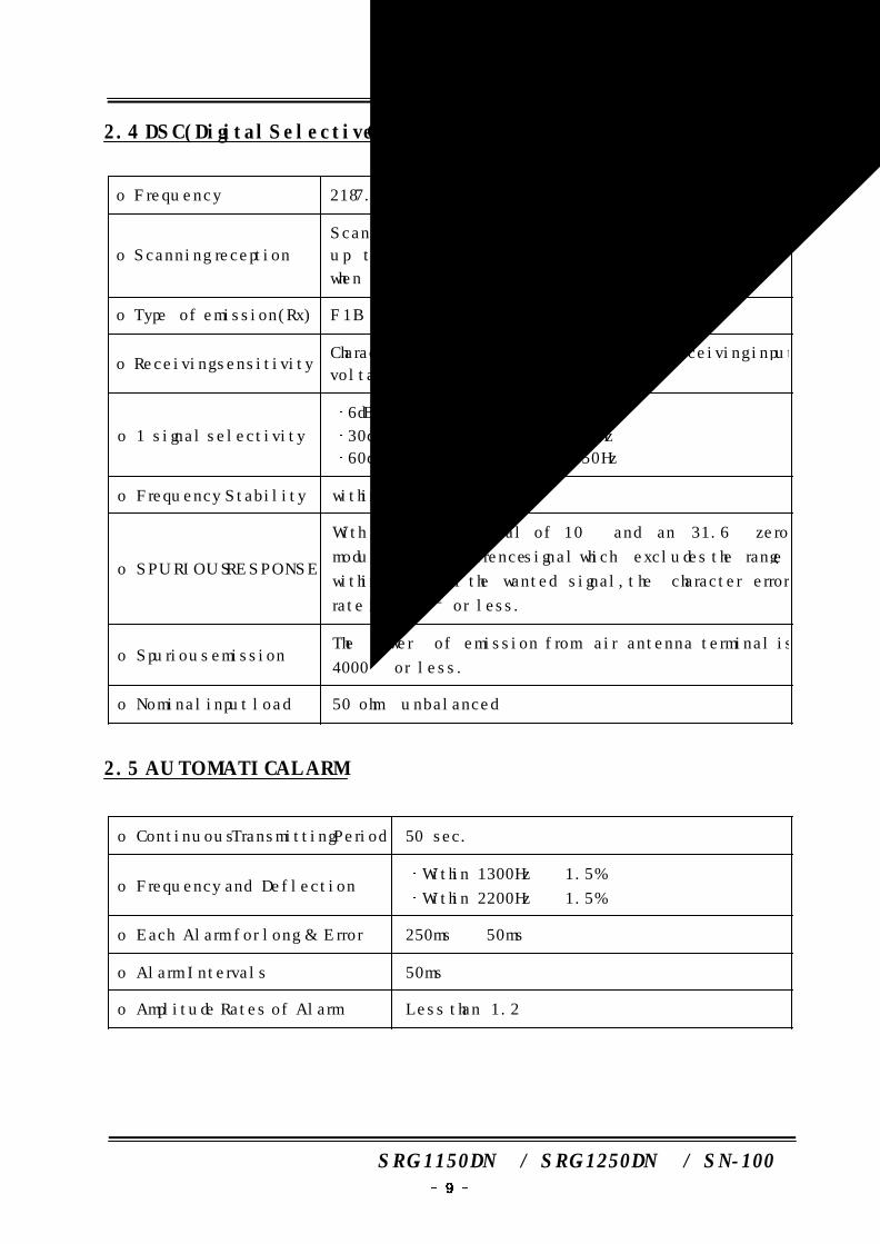
2.4 DSC(Digital Selective Calling) W/K RECEIVER
o Frequency 2187.5, 4207.5, 6312, 8414.5, 12577, 16804.5kHz
o Scanning reception
Scanning reception of above frequencies is continued
up to 2 seconds for each frequency and stop only
when detects a 100 baud dot pattern.
o Type of emission(Rx) F1B
o Receiving sensitivityCharacter error rate is 1×10⁻² or less at receiving input
voltage 1.
o 1 signal selectivity
6dB bandwidth : 270Hz - 300Hz
30dB bandwidth : within ± 380Hz
60dB bandwidth : within ± 550Hz
o Frequency Stability within ±10Hz
o SPURIOUS RESPONSE
With a wanted signal of 10 and an 31.6 zero
modulated interference signal which excludes the range
within 750Hz of the wanted signal, the character error
rate is 1×10⁻² or less.
o Spurious emissionThe power of emission from air antenna terminal is
4000 or less.
o Nominal input load 50 ohm unbalanced
2.5 AUTOMATIC ALARM
o Continuous Transmitting Period 50 sec.
o Frequency and DeflectionWithin 1300Hz ± 1.5%
Within 2200Hz ± 1.5%
o Each Alarm for long & Error 250ms ± 50ms
o Alarm Intervals 50ms
o Amplitude Rates of Alarm Less than 1.2
SRG-1150DN / SRG-1250DN / SN-100
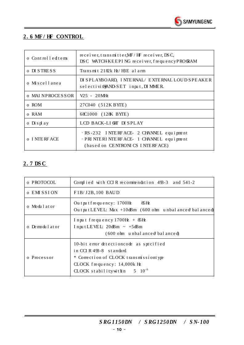
2.6 MF/HF CONTROL
o Controlled itemsreceiver, transmitter, MF/HF receiver, DSC,
DSC WATCH-KEEPING receiver, frequency PROGRAM
o DISTRESS Transmit 2182kHz/H3E alarm
o MiscellaneaDISPLAY BOARD, INTERNAL / EXTERNAL LOUD SPEAKER
selectivity HAND-SET input, DIMMER.
o MAIN PROCESSOR V25 - 20MHz
o ROM 27C040 (512K BYTE)
o RAM 68C1000 (128K BYTE)
o Display LCD BACK-LIGHT DISPLAY
o INTERFACE
RS-232 INTERFACE - 2 CHANNEL equipment
PRINTER INTERFACE - 1 CHANNEL equipment
(based on CENTRONICS INTERFACE )
2.7 DSC
o PROTOCOL Complied with CCIR recommendation 493-3 and 541-2
o EMISSION F1B/J2B, 100 BAUD
o Modulator Output frequency : 1700Hz ± 85Hz
Output LEVEL : Max +10dBm (600 ohm unbalanced/balanced)
o Demodulator
Input frequency 1700Hz + 85Hz
Input LEVEL : 20dBm ~ +5dBm
(600 ohm unbalanced/balanced)
o Processor
10-bit error detection code as specified
in CCIR 493-8 standard.
* Correction of CLOCK transmission type
CLOCK frequency : 14,000kHz
CLOCK stability : within ± 5×10⁻⁶
SRG-1150DN / SRG-1250DN / SN-100
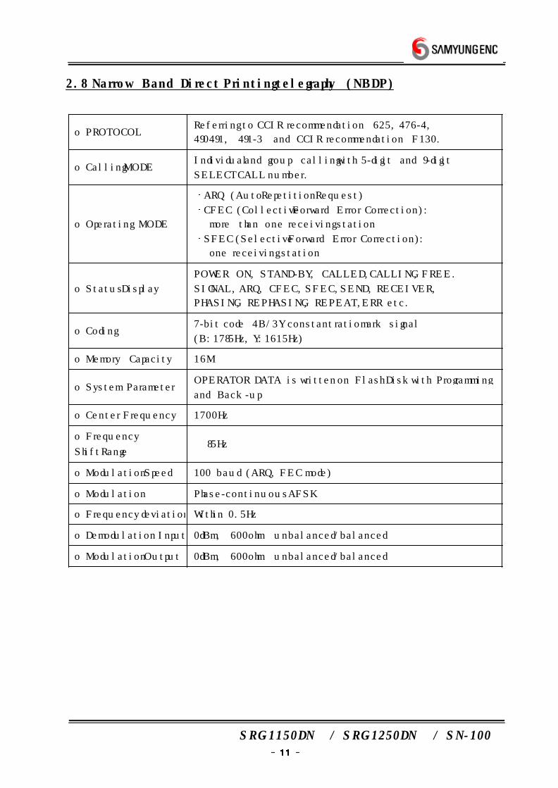
2.8 Narrow Band Direct Printing telegraphy (NBDP)
o PROTOCOLReferring to CCIR recommendation 625, 476-4,
490491, 491-3 and CCIR recommendation F130.
o Calling MODEIndividual and group calling with 5-digit and 9-digit
SELECT CALL number.
o Operating MODE
ARQ (Auto Repetition Request)
CFEC (Collective Forward Error Correction) :
more than one receiving station
SFEC (Selective Forward Error Correction) :
one receiving station
o Status Display
POWER ON, STAND-BY, CALLED, CALLING, FREE.
SIGNAL, ARQ, CFEC, SFEC, SEND, RECEIVER,
PHASING, REPHASING, REPEAT, ERR etc.
o Coding7-bit code 4B/3Y constant ratio mark signal
(B:1785Hz, Y:1615Hz)
o Memory Capacity 16M
o System ParameterOPERATOR DATA is written on Flash Disk with Programming
and Back-up
o Center Frequency 1700Hz
o Frequency
Shift Range± 85Hz
o Modulation Speed 100 baud (ARQ, FEC mode)
o Modulation Phase-continuous AFSK
o Frequency deviation Within 0.5Hz
o Demodulation Input 0dBm, 600ohm unbalanced/balanced
o Modulation Output 0dBm, 600ohm unbalanced/balanced
SRG-1150DN / SRG-1250DN / SN-100
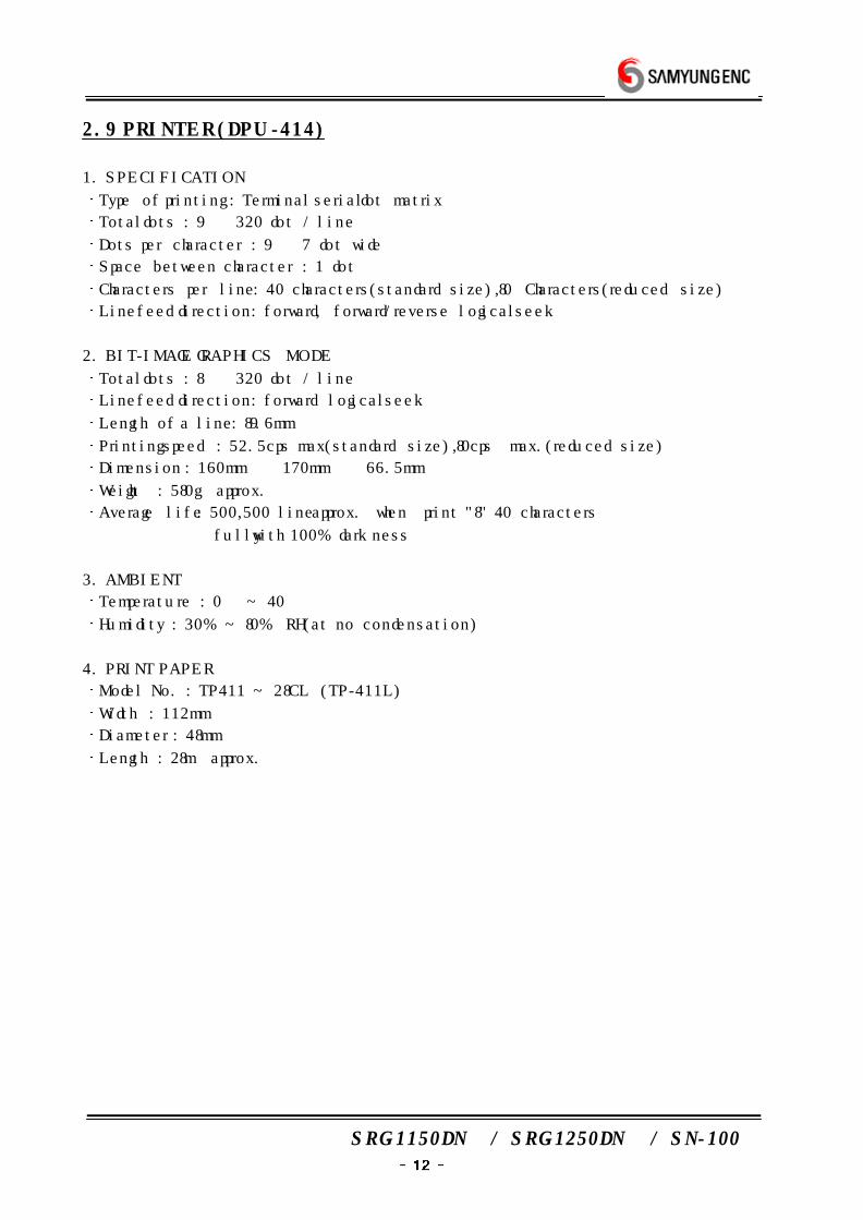
2.9 PRINTER (DPU-414)
1. SPECIFICATION
Type of printing : Terminal serial dot matrix
Total dots : 9 × 320 dot / line
Dots per character : 9 × 7 dot wide
Space between character : 1 dot
Characters per line : 40 characters(standard size), 80 Characters(reduced size)
Line feed direction : forward, forward/reverse logical seek
2. BIT-IMAGE GRAPHICS MODE
Total dots : 8 × 320 dot / line
Line feed direction : forward logical seek
Length of a line : 89.6mm
Printing speed : 52.5cps max(standard size), 80cps max.(reduced size)
Dimension : 160mm × 170mm × 66.5mm
Weight : 580g approx.
Average life : 500,500 line approx. when print "8" 40 characters
fully with 100% darkness
3. AMBIENT
Temperature : 0 ~ 40
Humidity : 30% ~ 80% RH(at no condensation)
4. PRINT PAPER
Model No. : TP411 ~ 28CL (TP-411L)
Width : 112mm
Diameter : 48mm
Length : 28m approx.
SRG-1150DN / SRG-1250DN / SN-100
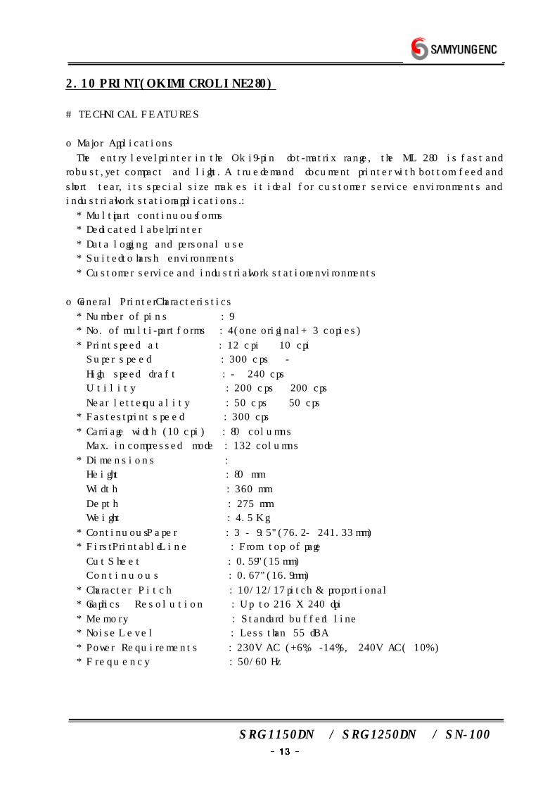
2.10 PRINT(OKI MICROLINE 280)
# TECHNICAL FEATURES
o Major Applications
The entry level printer in the Oki 9-pin dot-matrix range, the ML 280 is fast and
robust, yet compact and light. A true demand document printer with bottom feed and
short tear, its special size makes it ideal for customer service environments and
industrial workstation applications. :
* Multi part continuous forms
* Dedicated label printer
* Data logging and personal use
* Suited to harsh environments
* Customer service and industrial workstation environments
o General Printer Characteristics
* Number of p ins : 9
* No. of multi-part forms : 4(one original + 3 copies)
* Print speed a t : 12 cpi 10 cpi
Super speed : 300 cps -
High speed draft : - 240 cps
Ut i l i t y : 200 cps 200 cps
Near letter quality : 50 cps 50 cps
* Fastest print speed : 300 cps
* Carriage width (10 cpi) : 80 columns
Max. in compressed mode : 132 columns
* Dimensions :
Height : 80 mm
Wid th : 360 mm
Depth : 275 mm
Weight : 4.5 Kg
* Continuous Paper : 3 - 9.5"(76.2 - 241.33 mm)
* First Printable Line : From top of page
Cut Sheet : 0.59"(15 mm)
Continuous : 0.67"(16.9 mm)
* Character Pi tch : 10/12/17 pitch & proportional
* Graphics Resolution : Up to 216 X 240 dpi
* Memory : Standard buffer 1 line
* Noise Leve l : Less than 55 dBA
* Power Requirements : 230V AC (+6%, -14%), 240V AC(±10%)
* Frequency : 50/60 Hz
SRG-1150DN / SRG-1250DN / SN-100
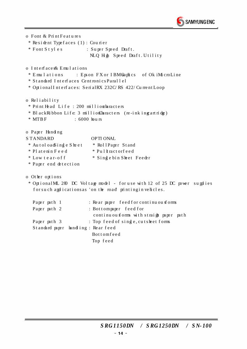
o Font & Print Features
* Resident Typefaces (1) : Courier
* Font Sty les : Super Speed Draft.
NLQ High Speed Draft. Utility
o Interfaces & Emulations
* Emulations : Epson FX or IBM Graphics of Oki MicroLine
* Standard Interfaces : Centronics Parallel
* Optional Interfaces : Serial RX 232C/RS 422/Current Loop
o Reliability
* Print Head Life : 200 million characters
* Black Ribbon Life : 3 million Characters (re-inking cartridge)
* MTBF : 6000 hours
o Paper Handing
STANDARD OPTIONAL
* Autoload Single Sheet * Roll Paper Stand
* Platen in Feed * Pull tractor feed
* Low tear-off * Single bin Sheet Feeder
* Paper end detection
o Other options
* Optional ML 280 DC Voltage model - for use with 12 of 25 DC power supplies
for such applications as 'on the road' printing in vehicles.
Paper path 1 : Rear paper feed for continuous forms
Paper path 2 : Bottom paper feed for
continuous forms with straight paper path
Paper path 3 : Top feed of single, cutsheet forms
Standard paper handling : Rear feed
Bottom feed
Top feed
SRG-1150DN / SRG-1250DN / SN-100
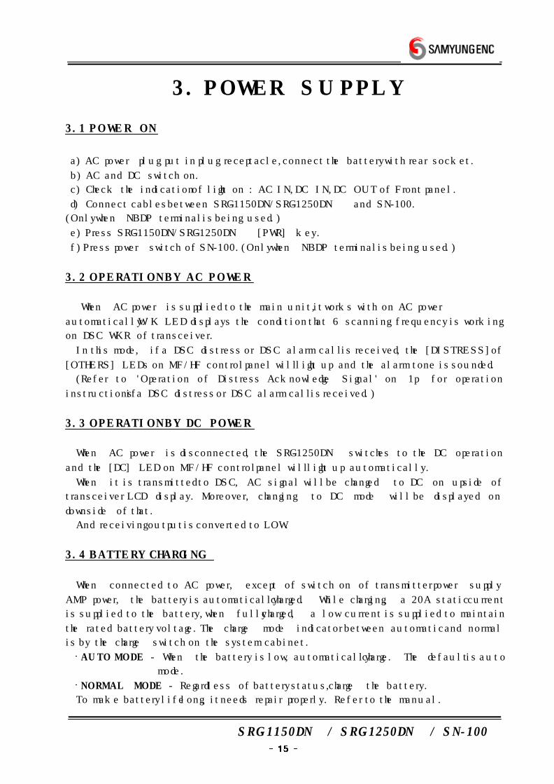
3. POWER SUPPLY
3.1 POWER ON
a) AC power plug put in plug receptacle, connect the battery with rear socket.
b) AC and DC switch on.
c) Check the indication of light on : AC IN, DC IN, DC OUT of Front panel.
d) Connect cables between SRG-1150DN/SRG-1250DN and SN-100.
(Only when NBDP terminal is being used.)
e) Press SRG-1150DN/SRG-1250DN [PWR] key.
f) Press power switch of SN-100.(Only when NBDP terminal is being used.)
3.2 OPERATION BY AC POWER
When AC power is supplied to the main unit, it works with on AC power
automatically. W/K LED displays the condition that 6 scanning frequency is working
on DSC WKR of transceiver.
In this mode, if a DSC distress or DSC alarm call is received, the [DISTRESS] of
[OTHERS] LEDs on MF/HF control panel will light up and the alarm tone is sounded.
(Refer to 'Operation of Distress Acknowledge Signal' on 1p for operation
instructions if a DSC distress or DSC alarm call is received.)
3.3 OPERATION BY DC POWER
When AC power is disconnected, the SRG-1250DN switches to the DC operation
and the [DC] LED on MF/HF control panel will light up automatically.
When it is transmitted to DSC, AC signal will be changed to DC on upside of
transceiver LCD display. Moreover, changing to DC mode will be displayed on
downside of that.
And receiving output is converted to LOW.
3.4 BATTERY CHARGING
When connected to AC power, except of switch on of transmitter power supply
AMP power, the battery is automatically charged. While charging, a 20A static current
is supplied to the battery, when fully charged, a low current is supplied to maintain
the rated battery voltage. The charge mode indicator between automatic and normal
is by the charge switch on the system cabinet.
AUTO MODE - When the battery is low, automatically charge. The default is auto
mode.
NORMAL MODE - Regardless of battery status, charge the battery.
To make battery life long, it needs repair properly. Refer to the manual.
SRG-1150DN / SRG-1250DN / SN-100
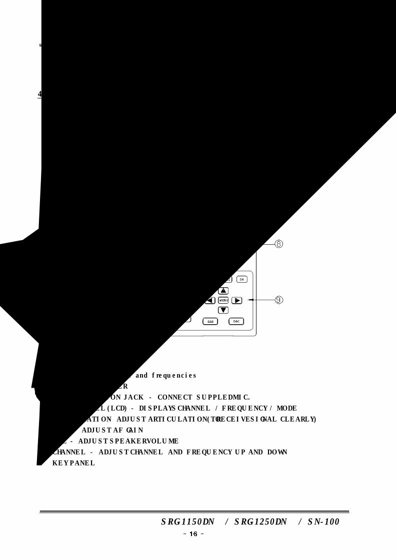
4. FRONT PANEL
4.1 EXPLANATION OF KEY, KNOB, LAMP OF MAIN UNIT
① List sheet of channels and frequencies
② INTERNAL SPEAKER
③ MIC. CONNECTION JACK - CONNECT SUPPLED MIC.
④ FRONT PANEL (LCD) - DISPLAYS CHANNEL / FREQUENCY / MODE
⑤ ARTICULATION - ADJUST ARTICULATION(TO RECEIVE SIGNAL CLEARLY)
⑥ GAIN - ADJUST AF GAIN
⑦ VOL - ADJUST SPEAKER VOLUME
⑧ CHANNEL - ADJUST CHANNEL AND FREQUENCY UP AND DOWN
⑨ KEY PANEL
SRG-1150DN / SRG-1250DN / SN-100
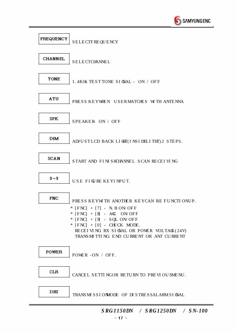
SELECT FREQUENCY
SELECT CHANNEL
1.4KHz TEST TONE SIGNAL - ON / OFF
PRESS KEY WHEN USER MATCHES WITH ANTENNA
SPEAKER - ON / OFF
ADJUST LCD BACK LIGHT(INSIDE LITHT) 2 STEPS.
START AND FINISH CHANNEL SCAN RECEIVING
USE FIGURE KEY INPUT.
PRESS KEY WITH ANOTHER KEY CAN BE FUNCTION UP.
* [FNC] + [7] - N.B ON/OFF
* [FNC] + [8] - AGC ON/OFF
* [FNC] + [9] - SQL ON/OFF
* [FNC] + [0] - CHECK MODE.
RECEIVING : RX SIGNAL OR POWER VOLTAGE(24V)
TRANSMITTING : END CURRENT OR ANT CURRENT
POWER -ON / OFF.
CANCEL SETTING OR RETURN TO PREVIOUS MENU.
TRANSMISSION MODE OF DISTRESS ALARM SIGNAL
SRG-1150DN / SRG-1250DN / SN-100
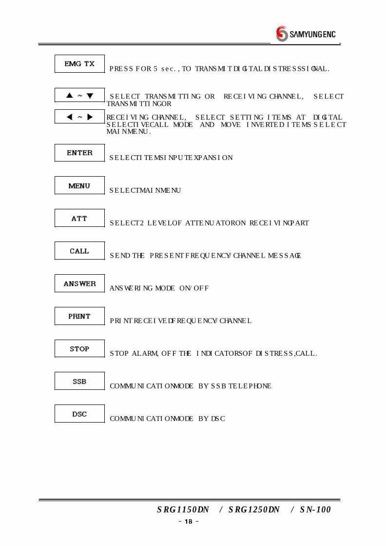
PRESS FOR 5 sec., TO TRANSMIT DIGITAL DISTRESS SIGNAL.
SELECT TRANSMITTING OR RECEIVING CHANNEL, SELECT TRANSMITTING OR
RECEIVING CHANNEL, SELECT SETTING ITEMS AT DIGITAL SELECTIVE CALL MODE AND MOVE INVERTED ITEMS SELECT
MAIN MENU.
SELECT ITEMS INPUT EXPANSION
SELECT MAIN MENU
SELECT 2 LEVEL OF ATTENUATOR ON RECEIVING PART
SEND THE PRESENT FREQUENCY/CHANNEL MESSAGE
ANSWERING MODE ON/OFF
PRINT RECEIVED FREQUENCY/CHANNEL
STOP ALARM, OFF THE INDICATORS OF DISTRESS, CALL.
COMMUNICATION MODE BY SSB TELEPHONE
COMMUNICATION MODE BY DSC
SRG-1150DN / SRG-1250DN / SN-100
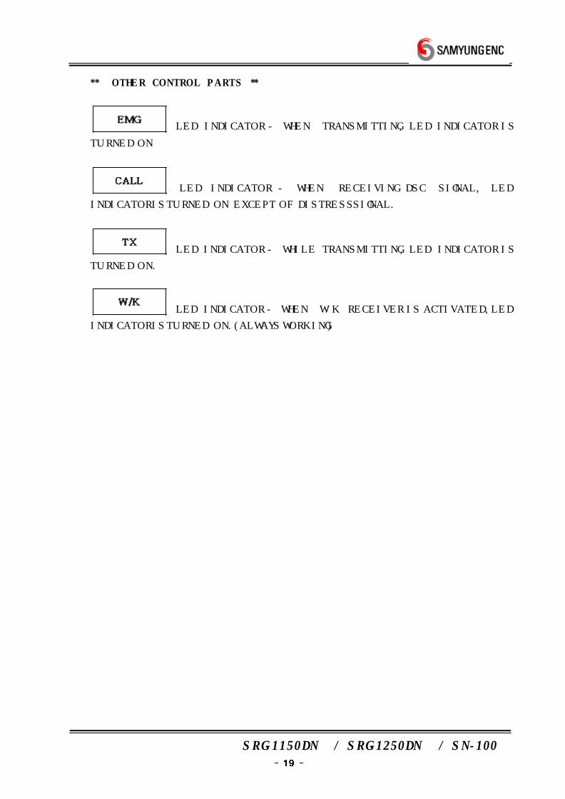
** OTHER CONTROL PARTS **
LED INDICATOR - WHEN TRANSMITTING, LED INDICATOR IS
TURNED ON
LED INDICATOR - WHEN RECEIVING DSC SIGNAL, LED
INDICATOR IS TURNED ON EXCEPT OF DISTRESS SIGNAL.
LED INDICATOR - WHILE TRANSMITTING, LED INDICATOR IS
TURNED ON.
LED INDICATOR - WHEN W/K RECEIVER IS ACTIVATED, LED
INDICATOR IS TURNED ON.(ALWAYS WORKING)
SRG-1150DN / SRG-1250DN / SN-100
4.2 LCD INDICATOR
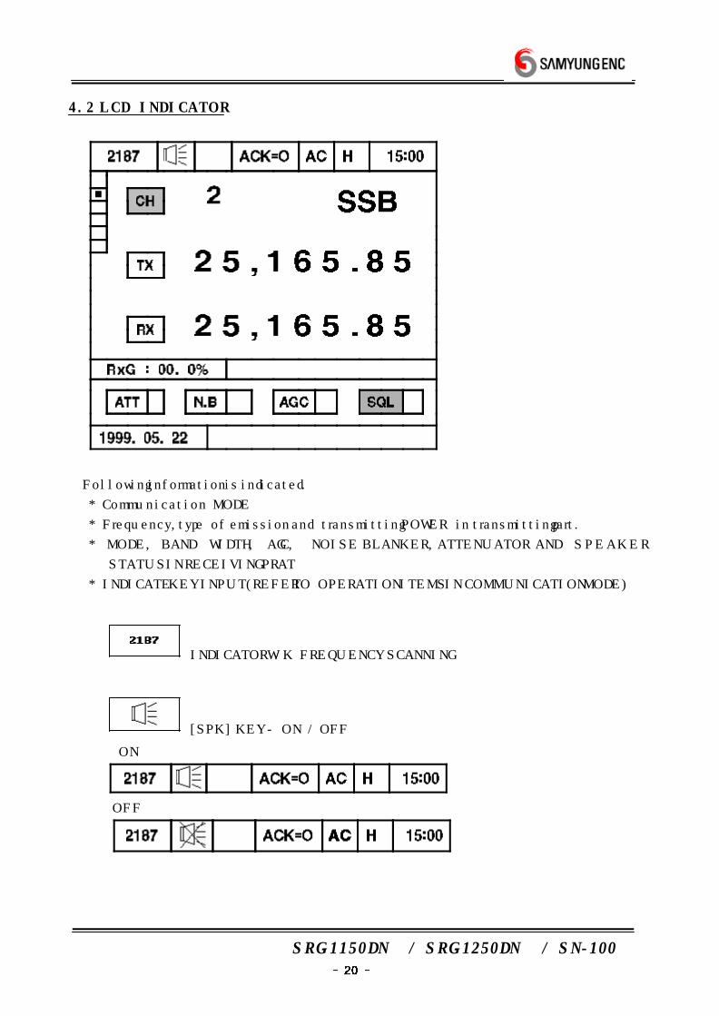
Following information is indicated.
* Communication MODE
* Frequency, type of emission and transmitting POWER in transmitting part.
* MODE, BAND WIDTH, AGC, NOISE BLANKER, ATTENUATOR AND SPEAKER
STATUS IN RECEIVING PRAT
* INDICATE KEY INPUT(REFER TO OPERATION ITEMS IN COMMUNICATION MODE)
INDICATOR W/K FREQUENCY SCANNING
[SPK] KEY - ON / OFF
ON
OFF
SRG-1150DN / SRG-1250DN / SN-100
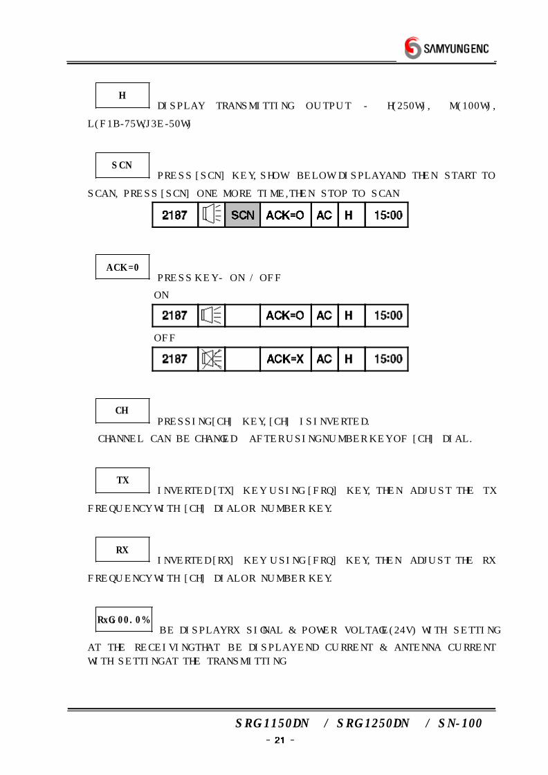
HDISPLAY TRANSMITTING OUTPUT - H(250W), M(100W),
L(F1B-75W,J3E-50W)
SCNPRESS [SCN] KEY, SHOW BELOW DISPLAY AND THEN START TO
SCAN, PRESS [SCN] ONE MORE TIME, THEN STOP TO SCAN
ACK=0PRESS KEY - ON / OFF
ON
OFF
CHPRESSING [CH] KEY, [CH] IS INVERTED.
CHANNEL CAN BE CHANGED AFTER USING NUMBER KEY OF [CH] DIAL.
TXINVERTED [TX] KEY USING [FRQ] KEY, THEN ADJUST THE TX
FREQUENCY WITH [CH] DIAL OR NUMBER KEY.
RXINVERTED [RX] KEY USING [FRQ] KEY, THEN ADJUST THE RX
FREQUENCY WITH [CH] DIAL OR NUMBER KEY.
RxG:00.0%BE DISPLAY RX SIGNAL & POWER VOLTAGE(24V) WITH SETTING
AT THE RECEIVING THAT BE DISPLAY END CURRENT & ANTENNA CURRENT
WITH SETTING AT THE TRANSMITTING
SRG-1150DN / SRG-1250DN / SN-100
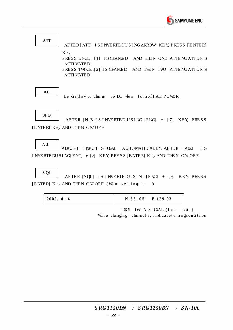
ATT AFTER [ATT] IS INVERTED USING ARROW KEY, PRESS [ENTER]
Key.
PRESS ONCE, [1] IS CHANGED AND THEN ONE ATTENUATION IS
ACTIVATED
PRESS TWICE,[2] IS CHANGED AND THEN TWO ATTENUATION IS
ACTIVATED
AC Be display to change to DC when turn off AC POWER.
N.B AFTER [N.B]IS INVERTED USING [FNC] + [7] KEY, PRESS
[ENTER] Key AND THEN ON/OFF
AGCADJUST INPUT SIGNAL AUTOMATICALLY, AFTER [AGC] IS
INVERTED USING [FNC] + [8] KEY, PRESS [ENTER] Key AND THEN ON/OFF.
SQL AFTER [SQL] IS INVERTED USING [FNC] + [9] KEY, PRESS
[ENTER] Key AND THEN ON/OFF. (When setting up : )
2002. 4. 6 N 35.05 E 129.03
: GPS DATA SIGNAL (Lat. Lot.)
While changing channels, indicate tuning condition
SRG-1150DN / SRG-1250DN / SN-100
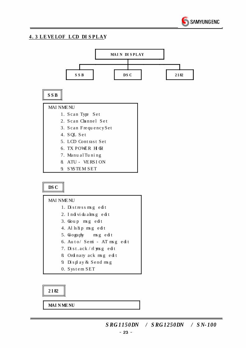
4.3 LEVEL OF LCD DISPLAY
M A I N DISPLAY
S S B D S C 2182
SSB
MAIN MENU
1. Scan Type Set
2. Scan Channel Set
3. Scan Frequency Set
4. SQL Set
5. LCD Contrast Set
6. TX POWER HIGH
7. Manual Tuning
8. ATU - VERSION
9. SYSTEM SET
DSC
MAIN MENU
1. Distress msg edit
2. Individual msg edit
3. Group msg edit
4. All ship msg edit
5. Geography msg edit
6. Auto / Semi - AT msg edit
7. Dist. ack/rly msg edit
8. Ordinary ack msg edit
9. Display & Send msg
0. System SET
2182
MAIN MENU
SRG-1150DN / SRG-1250DN / SN-100
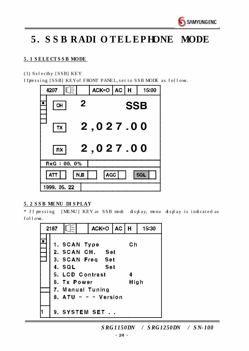
5. SSB RADIO TELEPHONE MODE
5.1 SELECT SSB MODE
(1) Select by [SSB] KEY
If pressing [SSB] KEY of FRONT PANEL, set to SSB MODE as follows.
5.2 SSB MENU DISPLAY
* If pressing [MENU] KEY at SSB mode display, menu display is indicated as
follows.

SRG-1150DN / SRG-1250DN / SN-100
(1) SCAN TYPE SET
a) Decide Scanning Channel or Frequency
b) After〔1.Scan Type Set〕 is inverted using [][] KEY,
press [ENTER] KEY and then display is indicated
c) In this mode, selected Scan Type is fixed.
ex) In case of Scan Type is ch. - Scan channel
In case of Freq. - Scan Freq.
d) Press [CLR] key, changed to main display.
(2) SCAN CHANNEL SET
a) Fix setting value in case of scanning Channel.
b) After [2.Scan Channel Set] is inverted using [][] KEY,
press [ENTER] KEY and then display is indicated.
Start
Last
Speed
:
:
:
001 - -
299
0
c) After moving cursor using [][][][] KEY, set value using
figure key and then press [ENTER] KEY
d) [Start] : Set starting channel of Scan Channel.
[Last] : Set last Scan Channel.
[Speed] :Set Scan Channel Speed
(3) SCAN FREQUENCY SET
a) Set setting value in case of scanning FREQUENCY
b) After [3.Scan Frequency Set] is converted using [][] KEY,
press [ENTER] KEY and then following display is indicated.
Start
Last
Speed
Step
:
:
:
:
00.500.0 - -
29,999,9 KHz
0
001(100Hz)
c) After moving cursor using [][][][] KEY, set value using
figure key and press [ENTER] KEY
d) [Start] : Set starting frequency of Scan Frequency.
[Last] : Set last frequency of Scan Frequency.
[Speed] : Set Scan Frequency Speed.
[Step] : Set Scanning frequency STEP(100HZ per 1Step)
ex ) When‘100’ - 10KHz STEP
SRG-1150DN / SRG-1250DN / SN-100
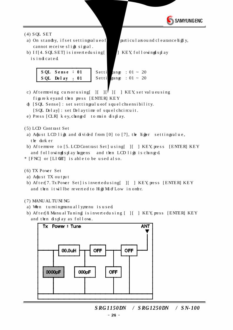
(4) SQL SET
a) On standby, if set setting value of SSB particular sound clearance highly,
cannot receive slight signal.
b) If [4.SQL SET] is inverted using [][] KEY, following display
is indicated.
SQL Sense
SQL Delay
:
:
01
01
Setting range : 01 ~ 20
Setting range : 01 ~ 20
c) After moving cursor using [][][][] KEY, set value using
figure key and then press [ENTER] KEY
d) [SQL Sense] : set setting value of squelch sensibility.
[SQL Delay] : set Delay time of squelch circuit.
e) Press [CLR] key, changed to main display.
(5) LCD Contrast Set
a) Adjust LCD light and divided from [0] to [7], the higher setting value,
the darker
b) After move to [5.LCD Contrast Set] using [][] KEY, press [ENTER] KEY
and following display happens and then LCD light is changed.
* [FNC] or [LIGHT] is able to be used also.
(6) TX Power Set
a) Adjust TX output
b) After [7.Tx Power Set] is inverted using [][] KEY, press [ENTER] KEY
and then it will be reverted to High/Mid/Low in order.
(7) MANUAL TUNING
a) When turning manually, menu is used.
b) After [8.Manual Tuning] is inverted using [][] KEY, press [ENTER] KEY
and then display as follows.
SRG-1150DN / SRG-1250DN / SN-100
c) Positioned adjustable element using [][] KEY.
d) After adjusting value using [][] KEY, press [ENTER] KEY
* If pressing [CLR] KEY, cancel adjusted value and return to first display.
(8) ATU - - - Version
a) Indicate ATU version
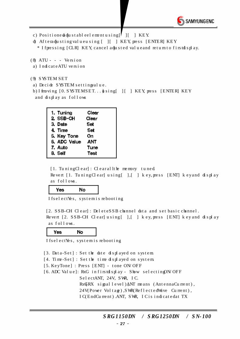
(9) SYSTEM SET
a) Decide SYSTEM setting value.
b)If moving [0.SYSTEM SET...] using [][] KEY, press [ENTER] KEY
and display as follows
① [1. Tuning Clear] : Clear all the memory tuned.
Revert [1. Tuning Clear] using [],[] key, press [ENT] key and display
as follows.
If select Yes, system is rebooting.
② [2. SSB-CH Clear] : Delete SSB channel data and set basic channel.
Revert [2. SSB-CH Clear] using [],[] key, press [ENT] key and display
as follows.
If select Yes, system is rebooting.
③ [3. Data-Set] : Set the date displayed on system.
④ [4. Time-Set] : Set the time displayed on system.
⑤ [5.Key Tone] : Press [ENT] - tone ON/OFF
⑥ [6.ADC Value] : RxG in first display - Show selecting ON/OFF
Select ANT, 24V, SWR, IC.
RxG(RX signal level), ANT means (Antenna Current),
24V(Power Voltage), SWR(Reflected Wave Current),
IC(End Current). ANT, SWR, IC is indicated at TX
SRG-1150DN / SRG-1250DN / SN-100
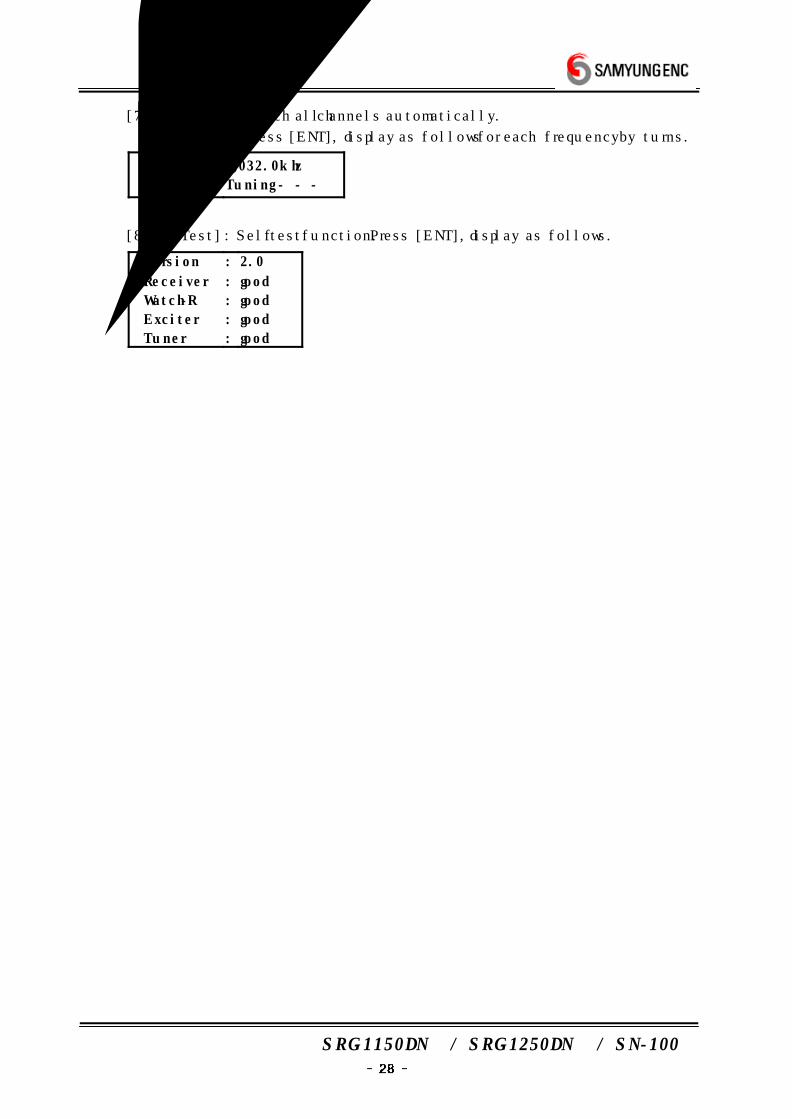
⑦ [7.Auto Tune] : Match all channels automatically.
Press [ENT], display as follows for each frequency by turns.
Freq
Tune
:
:
2,032.0khz
Tuning - - -
⑧ [8.Self Test] : Self test function. Press [ENT], display as follows.
Version
Receiver
Watch-R
Exciter
Tuner
:
:
:
:
:
2.0
good
good
good
good
SRG-1150DN / SRG-1250DN / SN-100
6. DIGITAL SELECTIVE
CALLING(DSC) MODE
6.1 THE SELECTION OF DSC MODE
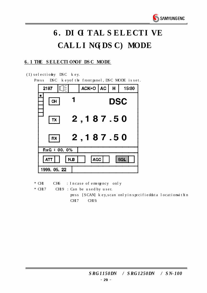
(1) selection by〔DSC〕key.
Press 〔DSC〕key of the front panel, DSC MODE is set.
* CH1 ˜ CH6 : In case of emergency only
* CH17 CH19 : Can be used by user.
press [SCAN] key, scan only in specified data location within
CH17 ˜ CH19.
SRG-1150DN / SRG-1250DN / SN-100
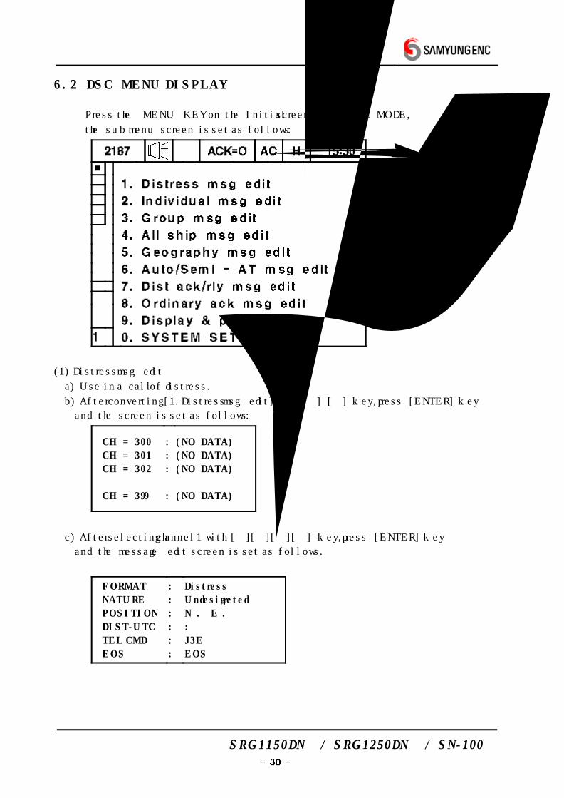
6.2 DSC MENU DISPLAY
Press the〔MENU〕KEY on the Initial screen of the DSC MODE,
the sub menu screen is set as follows :
(1) Distress msg edit
a) Use in a call of distress.
b) After converting [1.Distress msg edit] with [] [] key, press [ENTER] key
and the screen is set as follows :
CH = 300
CH = 301
CH = 302
…
CH = 399
:
:
:
:
(NO DATA)
(NO DATA)
(NO DATA)
…
(NO DATA)
c) After selecting channel1 with [][][][] key, press [ENTER] key
and the message edit screen is set as follows.
FORMAT
NATURE
POSITION
DIST-UTC
TEL CMD
EOS
:
:
:
:
:
:
Distress
Undesigreted
N . E .
:
J3E
EOS
SRG-1150DN / SRG-1250DN / SN-100
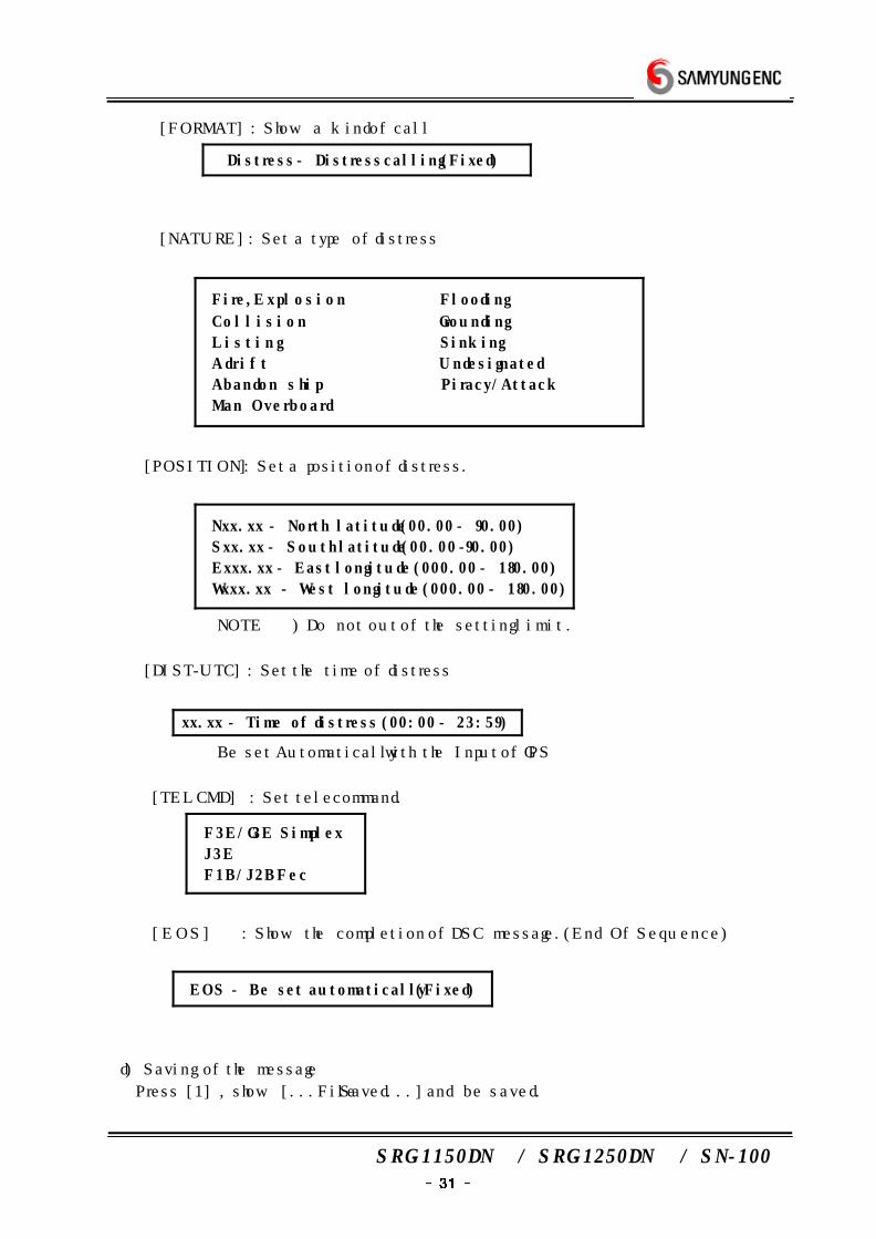
① [FORMAT] : Show a kind of call
Distress - Distress calling (Fixed)
② [NATURE] : Set a type of distress
Fire, E xp l o s i o n Flooding
C o l l i s i o n Grounding
L i s t i n g Sinking
A d r i f t Undesignated
Abandon s h i p Piracy/Attack
Man Overboard
③ [POSITION] : Set a position of distress.
Nxx.xx - North latitude (00.00 - 90.00)
Sxx.xx - South latitude (00.00 -90.00)
Exxx.xx - East longitude (000.00 - 180.00)
Wxxx.xx - West longitude (000.00 - 180.00)
NOTE!!) Do not out of the setting limit.
④ [DIST-UTC] : Set the time of distress
xx.xx - Time of distress (00:00 - 23:59)
Be set Automatically with the Input of GPS
⑤ [TEL CMD] : Set telecommand.
F3E/G3E Simplex
J3E
F1B/J2B Fec
⑥ [EOS] : Show the completion of DSC message.(End Of Sequence)
EOS - Be set automatically (Fixed)
d) Saving of the message
Press [1] , show [...File Saved...] and be saved.
SRG-1150DN / SRG-1250DN / SN-100
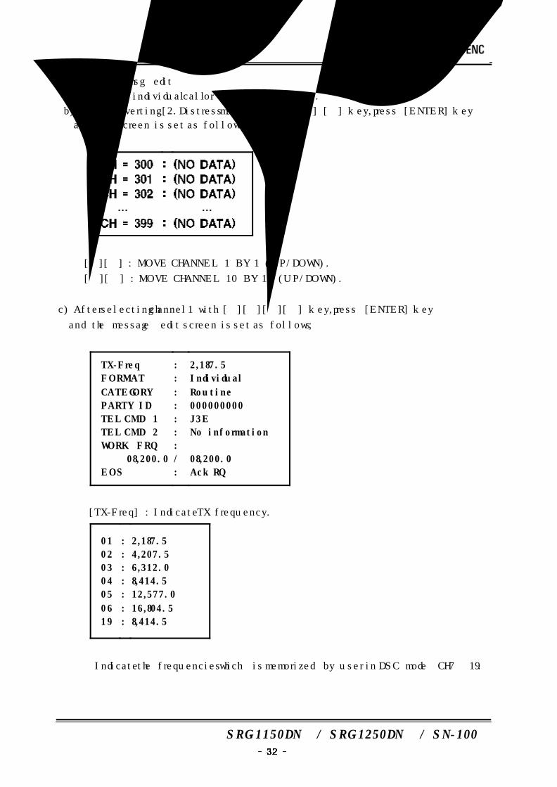
(2) Individual msg edit
a) Use in an individual call or ocean station call.
b) After converting [2.Distress msg edit] with [] [] key, press [ENTER] key
and the screen is set as follows :
※ [][] : MOVE CHANNEL 1 BY 1 (UP/DOWN).
[][] : MOVE CHANNEL 10 BY 10 (UP/DOWN).
c) After selecting channel1 with [][][][] key, press [ENTER] key
and the message edit screen is set as follows ;
TX-Freq
FORMAT
CATEGORY
PARTY ID
TEL CMD 1
TEL CMD 2
WORK FRQ
08,200.0
EOS
:
:
:
:
:
:
:
/
:
2,187.5
Individual
Routine
000000000
J3E
No information
08,200.0
Ack RQ
① [TX-Freq] : Indicate TX frequency.
01
02
03
04
05
06
19
:
:
:
:
:
:
:
2,187.5
4,207.5
6,312.0
8,414.5
12,577.0
16,804.5
8,414.5
※ Indicate the frequencies which is memorized by user in DSC mode CH7˜19.
SRG-1150DN / SRG-1250DN / SN-100
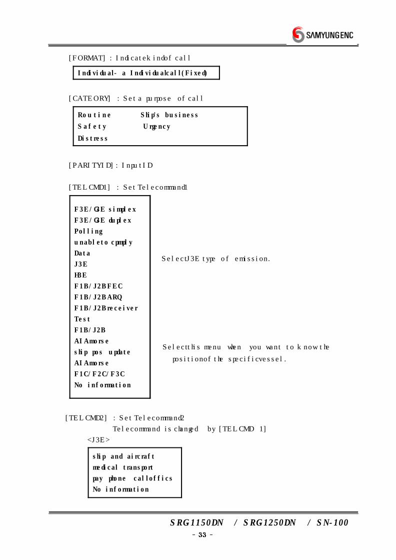
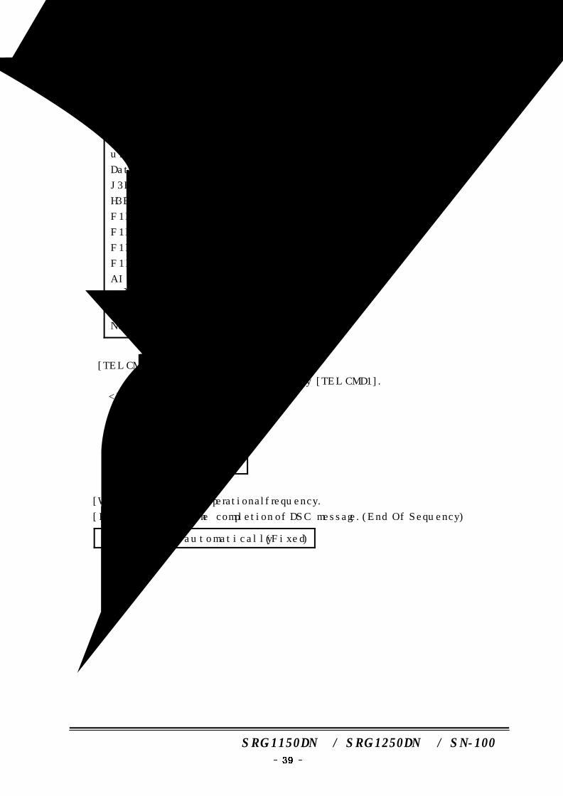
② [FORMAT] : Indicate kind of call
Individual - a Individual call (Fixed)
③ [CATEORY] : Set a purpose of call
Rou t i n e Ship's business
S a f e t y Urgency
Distress
④ [PARITY ID] : Input ID
⑤ [TEL CMD1] : Set Telecommand1
F3E/G3E simplex
F3E/G3E duplex
Polling
unable to cpmply
Data
J3E
H3E
F1B/J2B FEC
F1B/J2B ARQ
F1B/J2B receiver
Test
F1B/J2B
AIA morse
ship pos update
AIA morse
F1C/F2C/F3C
No information
→ Select J3E type of emission.
→ Select this menu when you want to know the
position of the specific vessel.
⑥ [TEL CMD2] : Set Telecommand2
Telecommand is changed by [TEL CMD 1]
<J3E>
ship and aircraft
medical transport
pay phone call offics
No information
SRG-1150DN / SRG-1250DN / SN-100
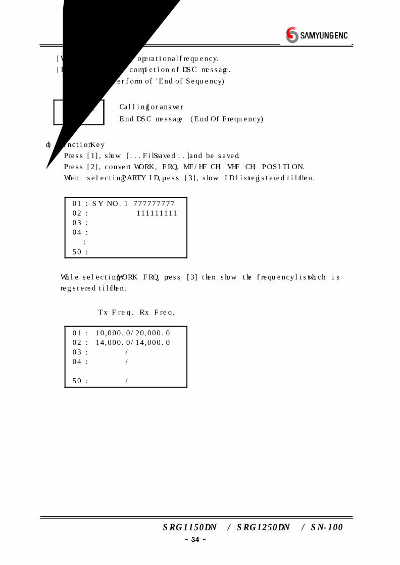
⑦ [WORK FRQ] : Set a operational frequency.
⑧ [EOS] : Show the completion of DSC message.
(Simpler form of 'End of Sequency)
ACK RQ
EOS
→ Calling for answer
→ End DSC message (End Of Frequency)
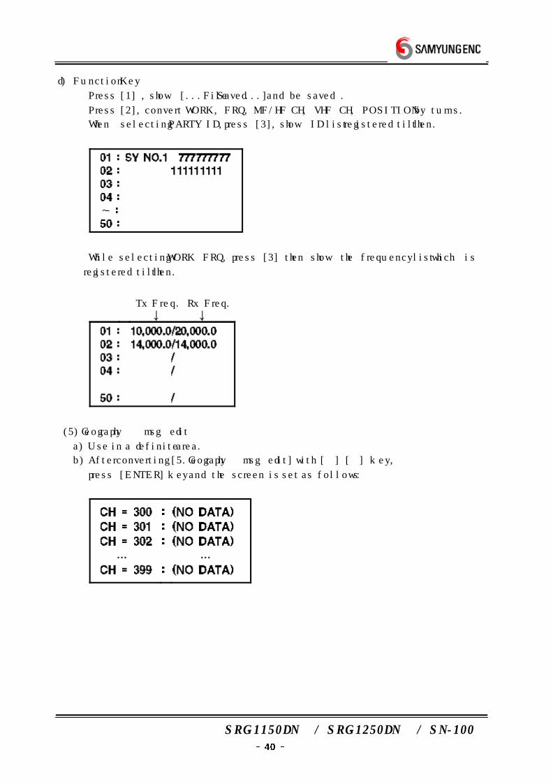
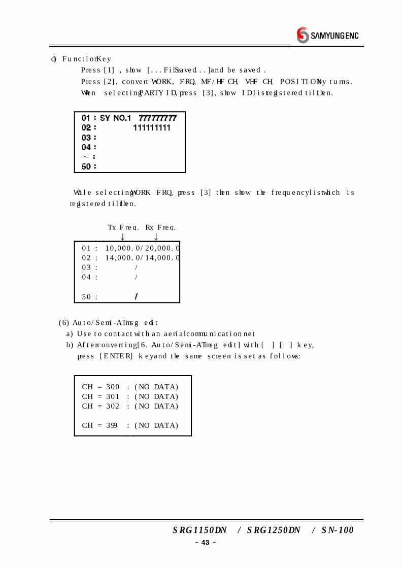
d) Function Key
① Press [1], show [...File Saved...] and be saved.
② Press [2], convert WORK, FRQ, MF/HF CH, VHF CH, POSITION.
③ When selecting PARTY ID, press [3], show ID list registered till then.
01 : SY NO.1 777777777
02 : 111111111
03 :
04 :
˜ :
50 :
④ While selecting WORK FRQ, press [3] then show the frequency list which is
registered till then.
Tx Freq. Rx Freq.
↓ ↓
01 : 10,000.0/20,000.0
02 : 14,000.0/14,000.0
03 : /
04 : /
50 : /
SRG-1150DN / SRG-1250DN / SN-100
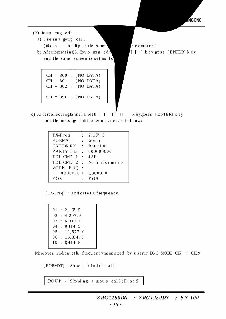
(3) Group msg edit
a) Use in a group call
(Group - a ship in the same company or character.)
b) After operating[3.Group msg edit] with [] [] key, press [ENTER] key
and the same screen is set as follows :
CH = 300
CH = 301
CH = 302
…
CH = 399
:
:
:
:
(NO DATA)
(NO DATA)
(NO DATA)
…
(NO DATA)
c) After selecting channel1 with [][][][] key, press [ENTER] key
and the message edit screen is set as follows :
TX-Freq
FORMAT
CATEGORY
PARTY ID
TEL CMD 1
TEL CMD 2
WORK FRQ
8,3000.0
EOS
:
:
:
:
:
:
:
/
:
2,187.5
Group
Routine
000000000
J3E
No information
8,3000.0
EOS
① [TX-Freq] : Indicate TX frequency.
01
02
03
04
05
06
19
:
:
:
:
:
:
:
2,187.5
4,207.5
6,312.0
8,414.5
12,577.0
16,804.5
8,414.5
※ Moreover, indicate the frequency memorized by user in DSC MODE CH7 ~ CH19.
② [FORMAT] : Show a kind of call.
GROUP - Showing a group call (Fixed)

SRG-1150DN / SRG-1250DN / SN-100
③ [CATEGORY] : Set a purpose of call
Routine Ship's business
Safety Urgency
Distress
④ [PARITY ID] : Input ID
⑤ [TEL CMD1] : Set telecommand
F3E/G3E simplex
F3E/G3E duplex
unable to comply
Data
J3E
H3E
F1B/J2B FEC
F1B/J2B ARQ
F1B/J2B receiver
F1B/J2B
AIA morse
AIA morse
F1C/F2C/F3C
No information
⑥ [TEL CMD2] : Sst telecommand2
Telecommand is changed by [TEL CMD 1].
<J3E>
ship and aircraft
medical transport
pay phone call offics
no information
⑦ [WORK FRQ] : Set a operational frequency.
⑧ [EOS] : Show the completion of DSC message (End Of Sequency)
EOS - Be set automatically (Fixed)
SRG-1150DN / SRG-1250DN / SN-100
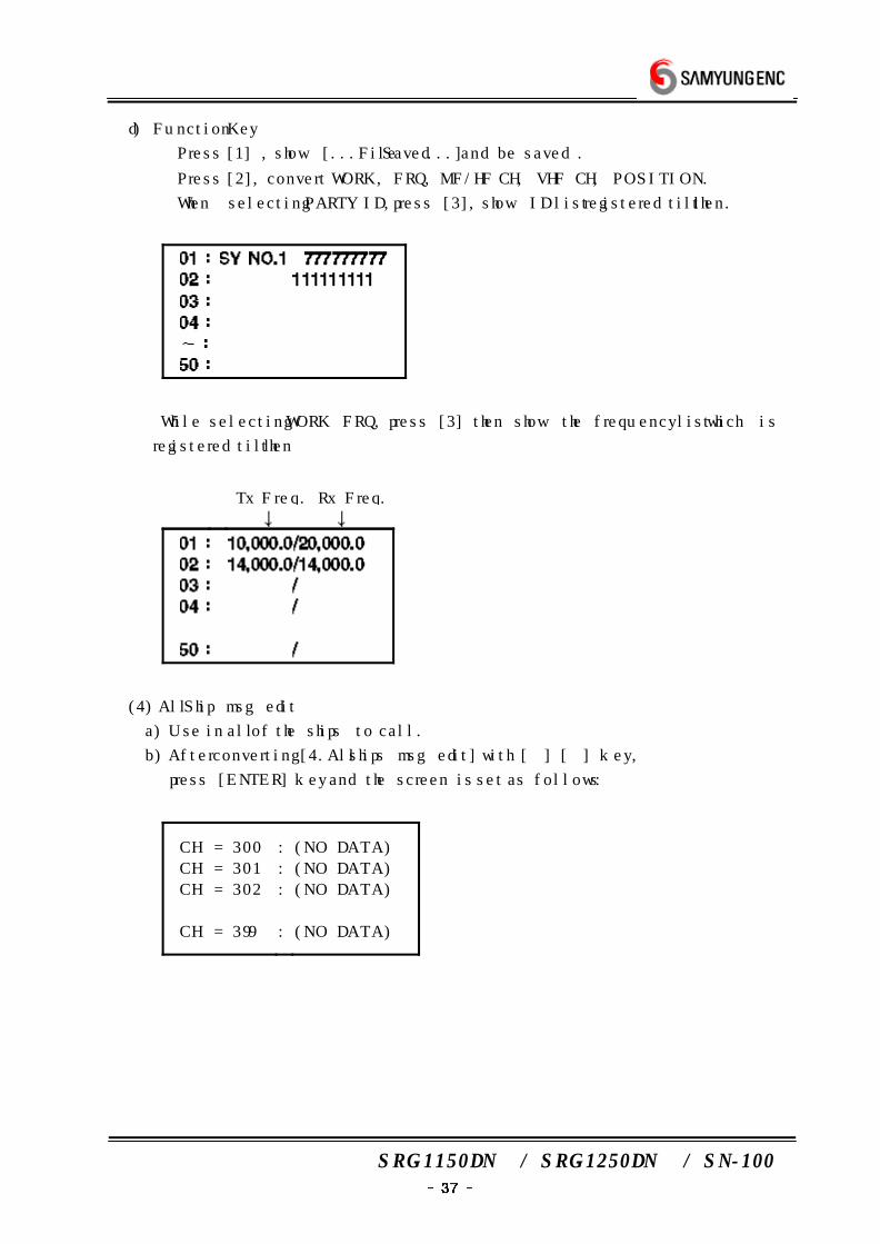
d) Function Key
① Press [1] , show [...File Saved...] and be saved .
② Press [2], convert WORK, FRQ, MF/HF CH, VHF CH, POSITION.
③ When selecting PARTY ID, press [3], show ID list registered till then.
④ While selecting WORK FRQ, press [3] then show the frequency list which is
registered till then
Tx Freq. Rx Freq.
(4) All Ship msg edit
a) Use in all of the ships to call.
b) After converting [4.All ships msg edit] with [] [] key,
press [ENTER] key and the screen is set as follows :
CH = 300
CH = 301
CH = 302
…
CH = 399
:
:
:
:
(NO DATA)
(NO DATA)
(NO DATA)
…
(NO DATA)
SRG-1150DN / SRG-1250DN / SN-100
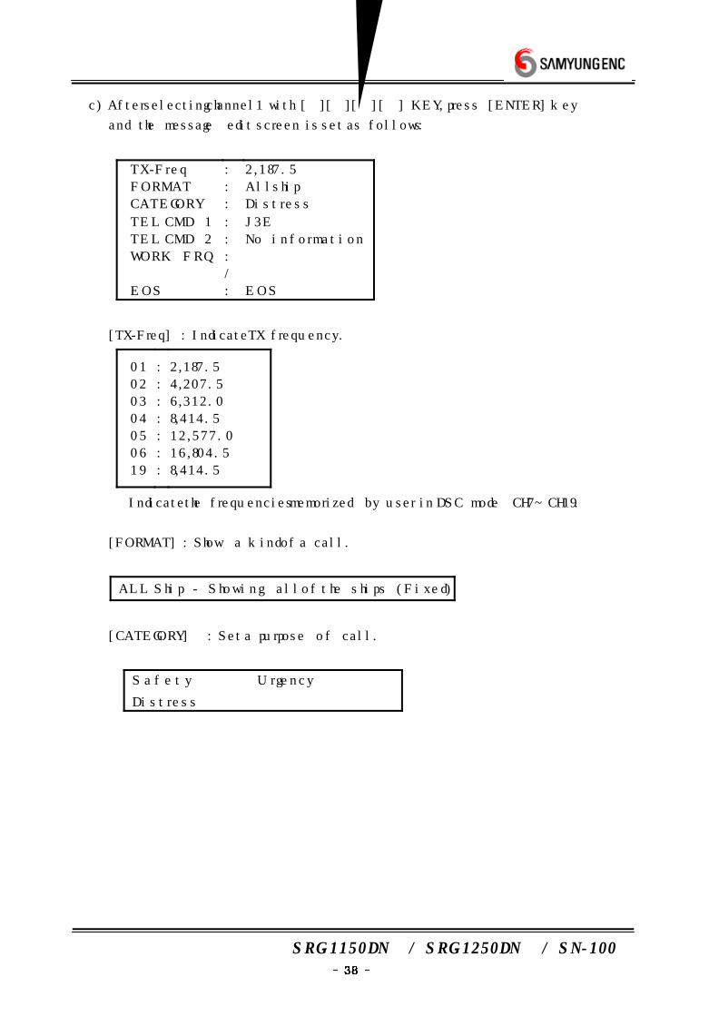
c) After selecting channel1 with [][][][] KEY, press [ENTER] key
and the message edit screen is set as follows :
TX-Freq
FORMAT
CATEGORY
TEL CMD 1
TEL CMD 2
WORK FRQ
EOS
:
:
:
:
:
:
/
:
2,187.5
All ship
Distress
J3E
No information
EOS
① [TX-Freq] : Indicate TX frequency.
01
02
03
04
05
06
19
:
:
:
:
:
:
:
2,187.5
4,207.5
6,312.0
8,414.5
12,577.0
16,804.5
8,414.5
※ Indicate the frequencies memorized by user in DSC mode CH7~CH19.
② [FORMAT] : Show a kind of a call.
ALL Ship - Showing all of the ships (Fixed)
③ [CATEGORY] : Set a purpose of call.
Safety Urgency
Distress ·
SRG-1150DN / SRG-1250DN / SN-100
④ [TEL CMD1] : Set telecommand1
F3E/G3E simplex
F3E/G3E duplex
unable to comply
Data
J3E
H3E
F1B/J2B FEC
F1B/J2B ARQ
F1B/J2B receiver
F1B/J2B
AIA morse
AIA morse
F1C/F2C/F3C
No information
⑤ [TEL CMD2] : Set telecommand2
Telecommand is changed by [TEL CMD1].
<J3E>
ship and aircraft
medical transport
pay phone call offics
no information
⑥ [WORK FRQ] : Set a operational frequency.
⑦ [EOS] : Show the completion of DSC message.(End Of Sequency)
EOS - Be set automatically (Fixed)
SRG-1150DN / SRG-1250DN / SN-100
d) Function Key
① Press [1] , show [...File Saved...] and be saved .
② Press [2], convert WORK, FRQ, MF/HF CH, VHF CH, POSITION by turns.
③ When selecting PARTY ID, press [3], show ID list registered till then.
④ While selecting WORK FRQ, press [3] then show the frequency list which is
registered till then.
Tx Freq. Rx Freq.
(5) Geography msg edit
a) Use in a definite area.
b) After converting [5.Geography msg edit] with [] [] key,
press [ENTER] key and the screen is set as follows :
SRG-1150DN / SRG-1250DN / SN-100
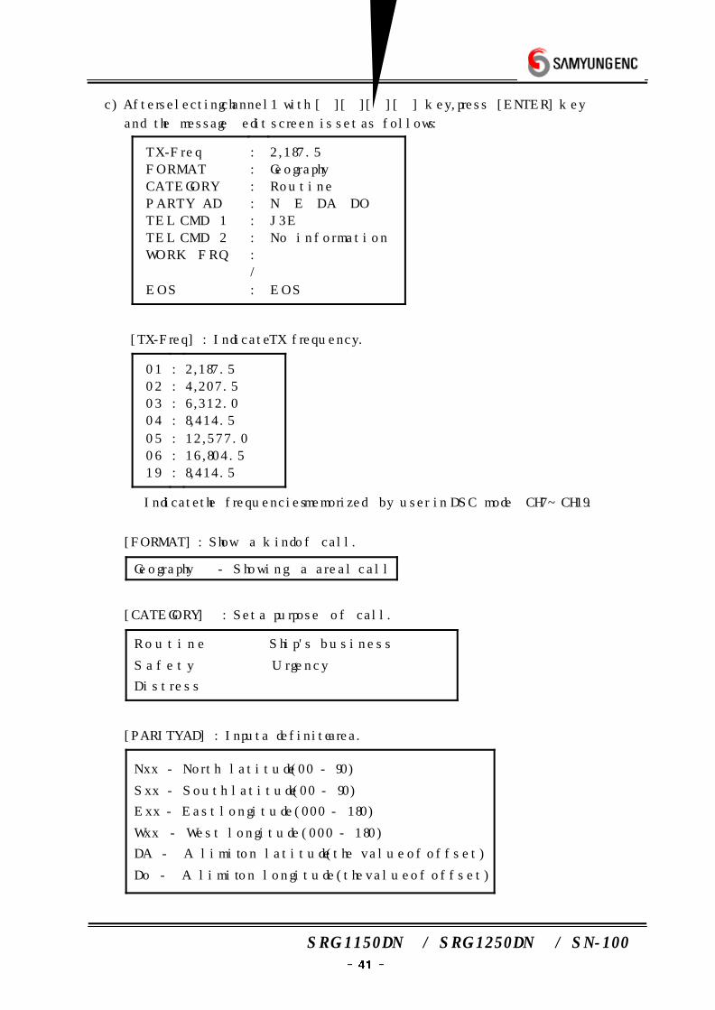
c) After selecting channel1 with [][][][] key, press [ENTER] key
and the message edit screen is set as follows :
TX-Freq
FORMAT
CATEGORY
PARTY AD
TEL CMD 1
TEL CMD 2
WORK FRQ
EOS
:
:
:
:
:
:
:
/
:
2,187.5
Geography
Routine
N E DA DO
J3E
No information
EOS
① [TX-Freq] : Indicate TX frequency.
01
02
03
04
05
06
19
:
:
:
:
:
:
:
2,187.5
4,207.5
6,312.0
8,414.5
12,577.0
16,804.5
8,414.5
※ Indicate the frequencies memorized by user in DSC mode CH7~CH19.
② [FORMAT] : Show a kind of call.
Geography - Showing a areal call
③ [CATEGORY] : Set a purpose of call.
Routine Ship's business
Safety Urgency
Distress
④ [PARITY AD] : Input a definite area.
Nxx - North latitude (00 - 90)
Sxx - South latitude (00 - 90)
Exx - East longitude (000 - 180)
Wxx - West longitude (000 - 180)
DA - A limit on latitude (the value of offset)
Do - A limit on longitude(the value of offset)
SRG-1150DN / SRG-1250DN / SN-100
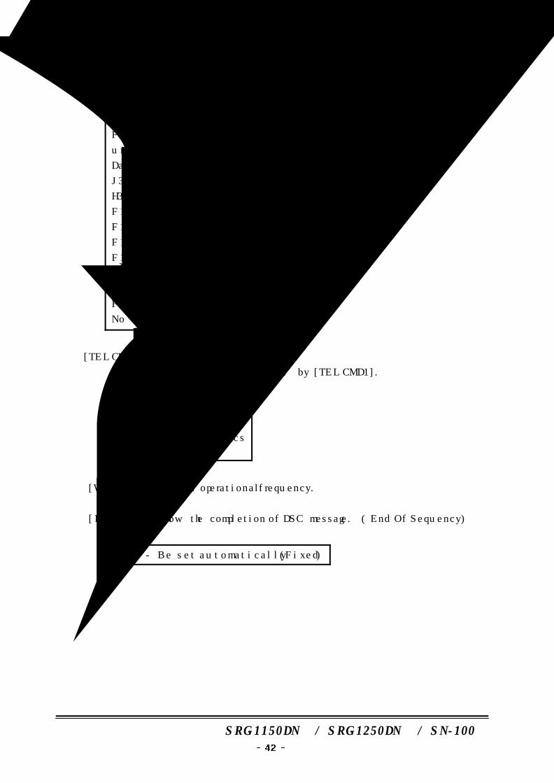
⑤ [TEL CMD1] : Set telecommand1.
F3E/G3E simplex
F3E/G3E duplex
unable to comply
Data
J3E
H3E
F1B/J2B FEC
F1B/J2B ARQ
F1B/J2B receiver
F1B/J2B
AIA morse
AIA morse
F1C/F2C/F3C
No information
⑥ [TEL CMD2] : Set telecommand2.
Telecommand is changed by [TEL CMD1].
<J3E>
ship and aircraft
medical transport
pay phone call offics
no information
⑦ [WORK FRQ] : Set a operational frequency.
⑧ [EOS] : Show the completion of DSC message. ( End Of Sequency)
EOS - Be set automatically (Fixed)
SRG-1150DN / SRG-1250DN / SN-100
d) Function Key
① Press [1] , show [...File Saved...] and be saved .
② Press [2], convert WORK, FRQ, MF/HF CH, VHF CH, POSITION by turns.
③ When selecting PARTY ID, press [3], show ID list registered till then.
④ While selecting WORK FRQ, press [3] then show the frequency list which is
registered till then.
Tx Freq. Rx Freq.
01 : 10,000.0/20,000.0
02 : 14,000.0/14,000.0
03 : /
04 : /
50 :
(6) Auto/Semi-AT msg edit
a) Use to contact with an aerial communication net
b) After converting [6. Auto/Semi-AT msg edit] with [] [] key,
press [ENTER] key and the same screen is set as follows :
CH = 300
CH = 301
CH = 302
…
CH = 399
:
:
:
:
(NO DATA)
(NO DATA)
(NO DATA)
…
(NO DATA)
SRG-1150DN / SRG-1250DN / SN-100
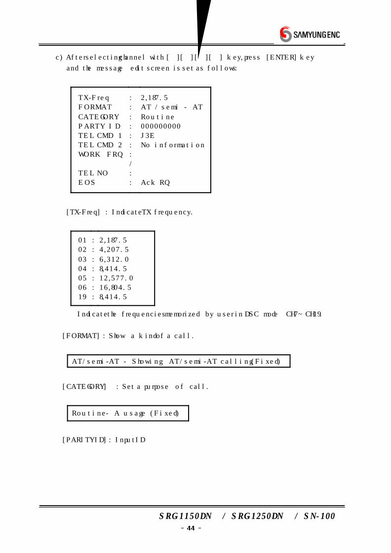
c) After selecting channel with [][][][] key, press [ENTER] key
and the message edit screen is set as follows :
TX-Freq
FORMAT
CATEGORY
PARTY ID
TEL CMD 1
TEL CMD 2
WORK FRQ
TEL NO
EOS
:
:
:
:
:
:
:
/
:
:
2,187.5
AT / semi - AT
Routine
000000000
J3E
No information
Ack RQ
① [TX-Freq] : Indicate TX frequency.
01
02
03
04
05
06
19
:
:
:
:
:
:
:
2,187.5
4,207.5
6,312.0
8,414.5
12,577.0
16,804.5
8,414.5
※ Indicate the frequencies memorized by user in DSC mode CH7~CH19.
② [FORMAT] : Show a kind of a call.
AT/semi-AT - Showing AT/semi-AT calling (Fixed)
③ [CATEGORY] : Set a purpose of call.
Routine - A usage (Fixed)
④ [PARITY ID] : Input ID
SRG-1150DN / SRG-1250DN / SN-100
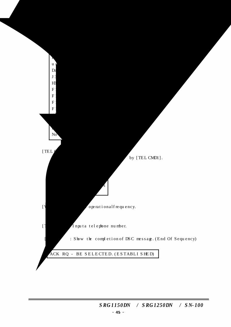
⑤ [TEL CMD1] : Set telecommand 1
F3E/G3E simplex
F3E/G3E duplex
unable to comply
Data
J3E
H3E
F1B/J2B FEC
F1B/J2B ARQ
F1B/J2B receiver
F1B/J2B
AIA morse
AIA morse
F1C/F2C/F3C
No information
⑥ [TEL CMD2] : Set telecommand 2
Telecommand is changed by [TEL CMD1].
<J3E>
ship and aircraft
medical transport
pay phone call offics
no information
⑦ [WORK FRQ] : Set a operational frequency.
⑧ [TEL NO] : Input a telephone number.
⑨ [EOS] : Show the completion of DSC message.(End Of Sequency)
ACK RQ - BE SELECTED .(ESTABLISHED)
SRG-1150DN / SRG-1250DN / SN-100
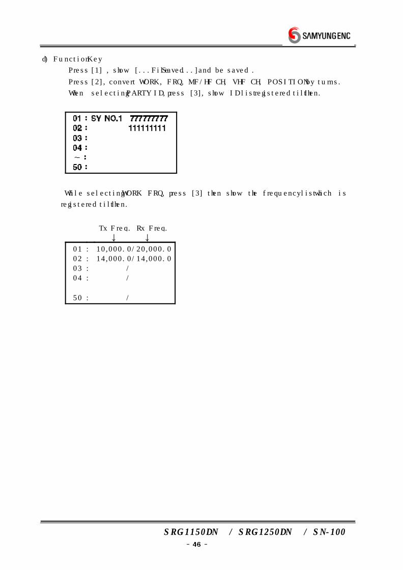
d) Function Key
① Press [1] , show [...File Saved...] and be saved .
② Press [2], convert WORK, FRQ, MF/HF CH, VHF CH, POSITION by turns.
③ When selecting PARTY ID, press [3], show ID list registered till then.
④ While selecting WORK FRQ, press [3] then show the frequency list which is
registered till then.
Tx Freq. Rx Freq.
01 : 10,000.0/20,000.0
02 : 14,000.0/14,000.0
03 : /
04 : /
50 : /
SRG-1150DN / SRG-1250DN / SN-100
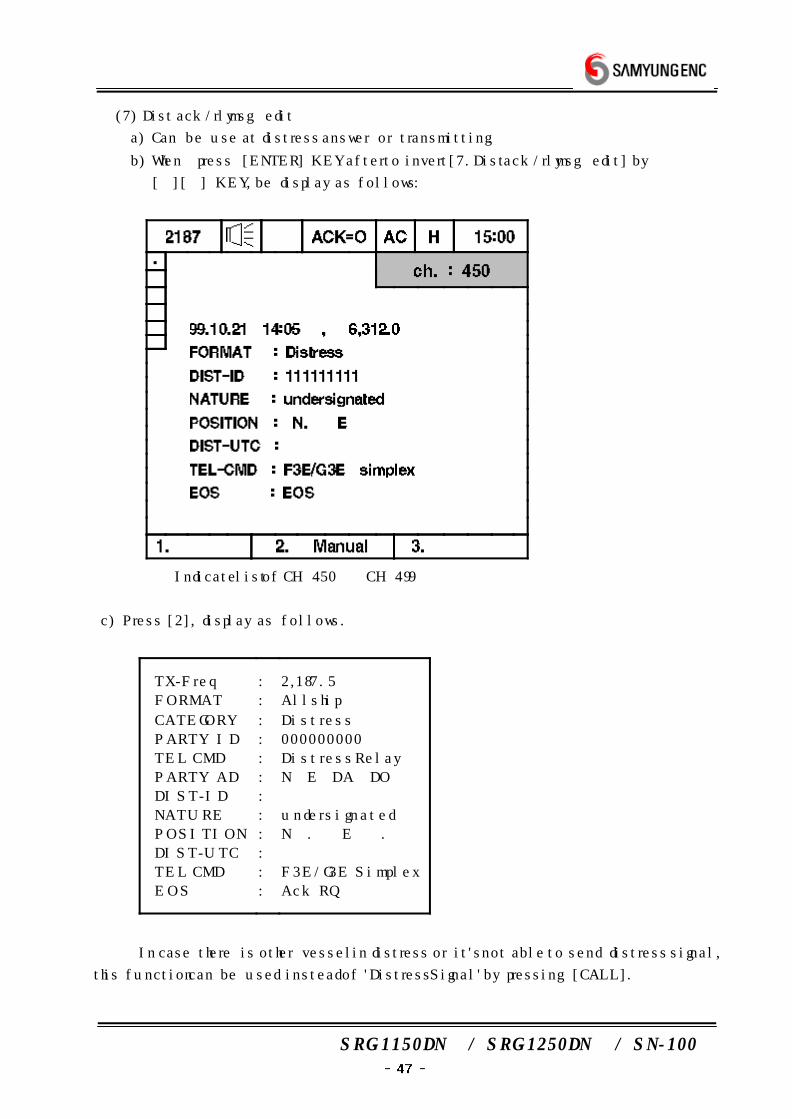
(7) Dist ack/rly msg edit
a) Can be use at distress answer or transmitting.
b) When press [ENTER] KEY after to invert [7.Dist ack/rly msg edit] by
[][] KEY, be display as follows :
※ Indicate list of CH 450 ˜ CH 499
c) Press [2], display as follows.
TX-Freq
FORMAT
CATEGORY
PARTY ID
TEL CMD
PARTY AD
DIST-ID
NATURE
POSITION
DIST-UTC
TEL CMD
EOS
:
:
:
:
:
:
:
:
:
:
:
:
2,187.5
All ship
Distress
000000000
Distress Relay
N E DA DO
undersignated
N . E .
F3E/G3E Simplex
Ack RQ
※ In case there is other vessel in distress or it's not able to send distress signal,
this function can be used instead of 'Distress Signal' by pressing [CALL].

SRG-1150DN / SRG-1250DN / SN-100
① [TX-Freq] : Indicate TX frequency.
01
02
03
04
05
06
:
:
:
:
:
:
2,187.5
4,207.5
6,312.0
8,414.5
12,577.0
16,804.5
※ Indicate the frequencies memorized by user in DSC mode CH7˜CH19.
② [FORMAT] : Show a kind of a call.
Geography
Group
All ship
Individual
③ [CATEGORY] : Set a purpose of call.
Distress - (Fixed)
④ [PARITY ID] : Input ID. (Geography, in case of all ship - ×)
⑤ [TEL CMD] : Selet telecommand. ( In case of all ship - )
Distress AcK
Distress Relay
→ In case let know the receiving the distress signal. → In case of relaying broadcast cause the distance is far from shore station.
⑥ [PARTY AD] : Input specific area.(Group, All ship individual - ×)
⑦ [DIST-ID] : Input the ID of the vessel in distress.
⑧ [NATURE] : Set the type of Distress.
Fire, Explosion Flooding
Collision Grounding
Listing Sinking
Adrift Undesignated
Abandon ship Piracy/Attack
Man Overboard
SRG-1150DN / SRG-1250DN / SN-100
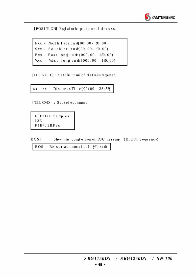
⑨ [POSITION] : Explain the position of distress.
Nxx - North latitude (00.00 - 90.00)
Sxx - South latitude (00.00 - 90.00)
Exx - East longitude (000.00 - 180.00)
Wxx - West longitude (000.00 - 180.00)
⑩ [DIST-UTC] : Set the time of distress happened.
xx : xx - Distress Time(00:00 - 23:59)
⑪ [TEL CMD] : Set telecommand.
F3E/G3E Simplex
J3E
F1B/J2B Fec
⑫ [EOS] : Show the completion of DSC message (End Of Sequency)
EOS - Be set automatically (Fixed)
SRG-1150DN / SRG-1250DN / SN-100
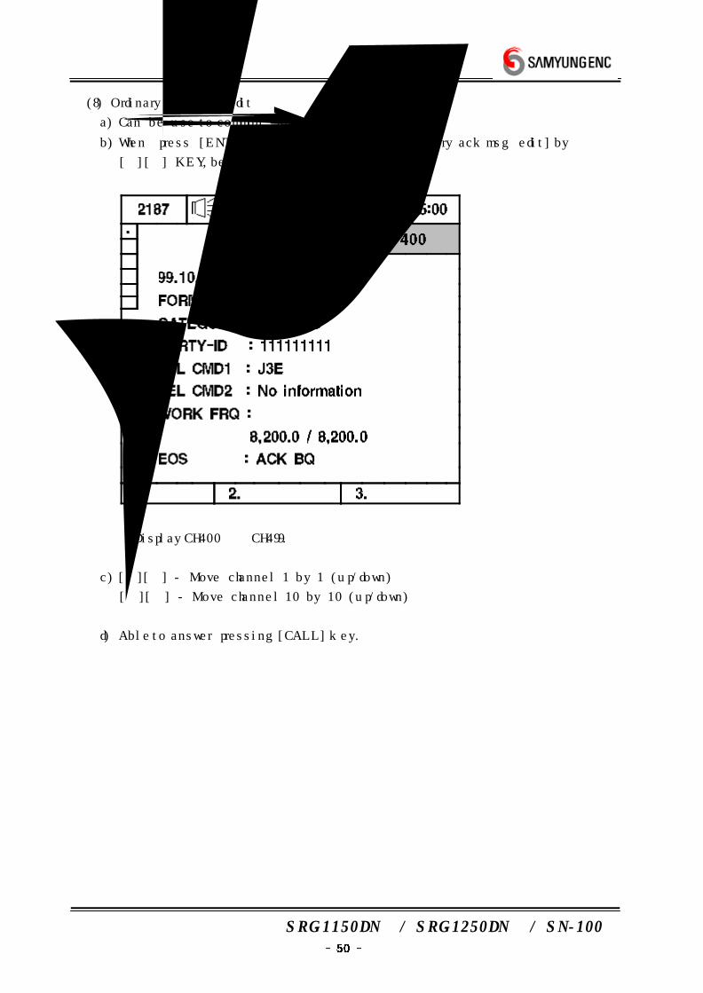
(8) Ordinary ack msg edit
a) Can be use to common answer call.
b) When press [ENTER] KEY after to invert [8.Ordinary ack msg edit] by
[][] KEY, be display as follows :
※ Display CH400 ˜ CH499.
c) [][] - Move channel 1 by 1 (up/down)
[][] - Move channel 10 by 10 (up/down)
d) Able to answer pressing [CALL] key.
SRG-1150DN / SRG-1250DN / SN-100
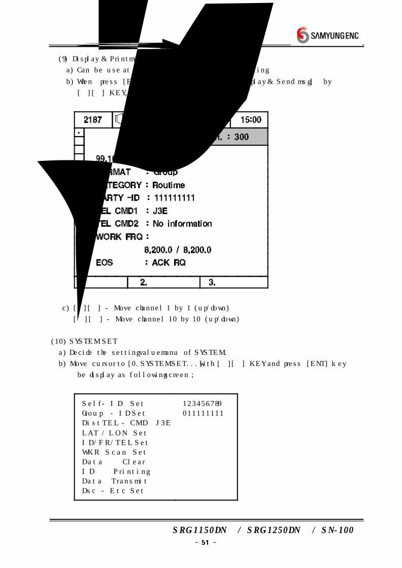
(9) Display & Print msg
a) Can be use at checking written Message or printing.
b) When press [ENTER] KEY after to invert [9.Display & Send msg] by
[][] KEY, be display as follows screen.
c) [][] - Move channel 1 by 1 (up/down)
[][] - Move channel 10 by 10 (up/down)
(10) SYSTEM SET
a) Decide the setting value manu of SYSTEM.
b) Move cursor to [0.SYSTEM SET...] with [][] KEY and press [ENT] key
be display as following screen ;
Self - ID Set
Group - ID Set
Dist TEL - CMD J3E
LAT / LON Set
ID/FR/TEL Set
WKR Scan Set
Data Clear
ID Printing
Data Transmit
Dsc - Etc Set
123456789
011111111

SRG-1150DN / SRG-1250DN / SN-100
c) ① [Self-ID] : Input ID of station.
② [Group-ID] : Input GROUP ID of station.
③ [Dist Tel-CMD] : Select Telecommand.
F3E/G3E Simplex
J3E
F1B/J2B Fec
④ [LAT / LON Set] : Set Lat/Lon of GPS by hand-operation.
→ Position → Set the time following Greenwich Time
⑤ [ID/FR/TEL Set] : Edit ID/Operating frequency/Auto answering ID/Telephone
No.
ID EDIT
Auto - Ack.ID EDIT
Work Frequency EDIT
Telephone - No EDIT
Ex) Press [ENT] key on the line you want to edit, display as follows.
(Following display is selecting ID EDIT)
Press [ENT] key one more time, display as follows.
Using [] [] [] [] keys select the spot you want, then you can input.
1 2 3 4 5 6 7 8 9 0 - ( )
A B C D E F G H I J K L M
N O P Q R S T U V W X Y Z
ㄱ ㄲ ㄴ ㄷ ㄸ ㄹ ㅁ ㅂ ㅃ ㅅ
ㅆ ㅇ ㅈ ㅉ ㅊ ㅋ ㅌ ㅍ ㅎ
ㅏ ㅐ ㅑ ㅒ ㅕ ㅓ ㅔ ㅕ
ㅖ ㅗ ㅛ ㅜ ㅠ ㅡ ㅣ
Input :
SRG-1150DN / SRG-1250DN / SN-100
Then if you press [CNR] key, display as follows.
000000000
(Blank No. will be filled with 0)
If you input "SY ENC", display as follows.
01 : SY ENC 101010000
02 :
03 :
04 :
˜ :
50 :
※ It can be done in [ID EDIT] only.
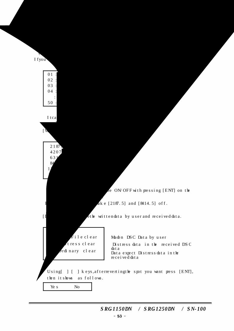
⑥ [WKR Scan Set] : Scanning W/K frequency ON/OFF
2187.5 on
4207.5 on
6312.0 off
8414.5 on
12577.5 off
16804.5 off
※ Using [] [] keys it can be ON/OFF with pressing [ENT] on the
frequency which you want.
But, it is impossible to make [2187.5] and [8414.5] off.
⑦ [Data Clear] : Delete the written data by user and received data.
DSC Made-File clear
DSC Distress clear
DSC Ordinary clear
→ Maden DSC Data by user
→ Distress data in the received DSC data→ Data expect Distress data in the received data
※ Using [] [] keys, after reverting the spot you want press [ENT],
then it shows as follows.
Yes No
SRG-1150DN / SRG-1250DN / SN-100
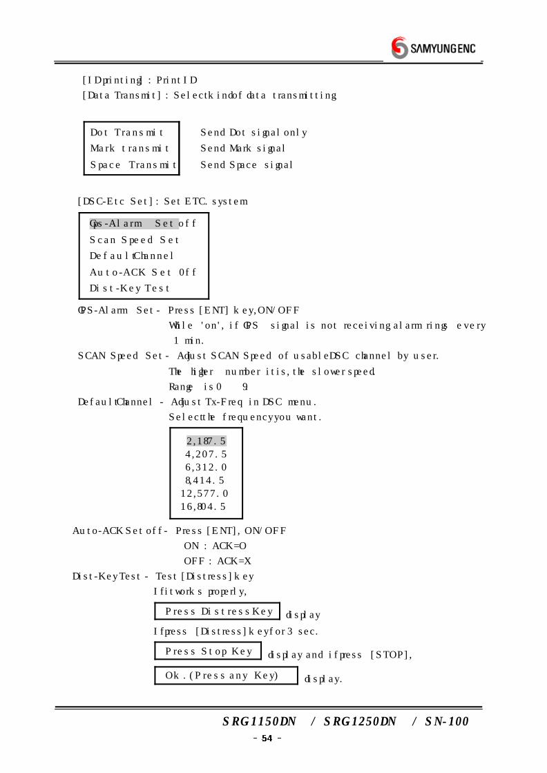
⑧ [ID printing] : Print ID
⑨ [Data Transmit] : Select kind of data transmitting.
Dot Transmit
Mark transmit
Space Transmit
→ Send Dot signal only
→ Send Mark signal
→ Send Space signal
⑩ [DSC-Etc Set] : Set ETC. system
Gps-Alarm Set off
Scan Speed Set
Default Channel
Auto-ACK Set 0ff
Dist-Key Test
※ GPS-Alarm Set - Press [ENT] key, ON/OFF
While 'on', if GPS signal is not receiving alarm rings every
1 min.
SCAN Speed Set - Adjust SCAN Speed of usable DSC channel by user.
The higher number it is, the slower speed.
Range is 0 ˜ 9.
Default Channel - Adjust Tx-Freq in DSC menu.
Select the frequency you want.
2,187.5
4,207.5
6,312.0
8,414.5
12,577.0
16,804.5
Auto-ACK Set off - Press [ENT], ON/OFF
① ON : ACK=O
② OFF : ACK=X
Dist-Key Test - Test [Distress] key
If it works properly,
Press Distress Key display
If press [Distress] key for 3 sec.
Press Stop Key display and if press [STOP],
Ok. (Press any Key) display.
SRG-1150DN / SRG-1250DN / SN-100
7. TRANSMITTER OF
DISTRESS SIGNAL
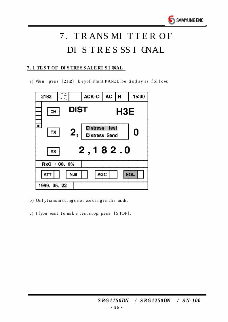
7.1 TEST OF DISTRESS ALERT SIGNAL
a) When press [2182] key of Front PANEL, be display as follows :
b) Only transmitting is not working in this mode.
c) If you want to make test stop, press [STOP].
SRG-1150DN / SRG-1250DN / SN-100
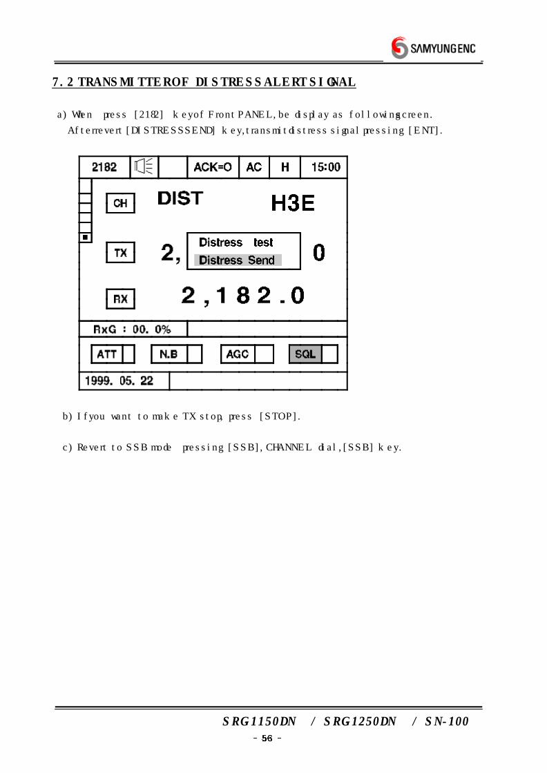
7.2 TRANSMITTER OF DISTRESS ALERT SIGNAL
a) When press [2182] key of Front PANEL, be display as following screen.
After revert [DISTRESS SEND] key, transmit distress signal pressing [ENT].
b) If you want to make TX stop, press [STOP].
c) Revert to SSB mode pressing [SSB], CHANNEL dial, [SSB] key.
SRG-1150DN / SRG-1250DN / SN-100
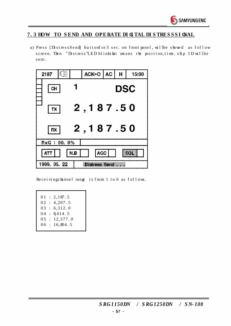
7.3 HOW TO SEND AND OPERATE DIGITAL DISTRESS SIGNAL
a) Press [Distress Send] button for 3 sec. on front panel, will be showed as follow
screen. Then "Distress" LED blink that means the position, time, ship ID will be
sent.
※ Receiving channel range is from 1 to 6 as follows.
01
02
03
04
05
06
:
:
:
:
:
:
2,187.5
4,207.5
6,312.0
8,414.5
12,577.0
16,804.5
SRG-1150DN / SRG-1250DN / SN-100
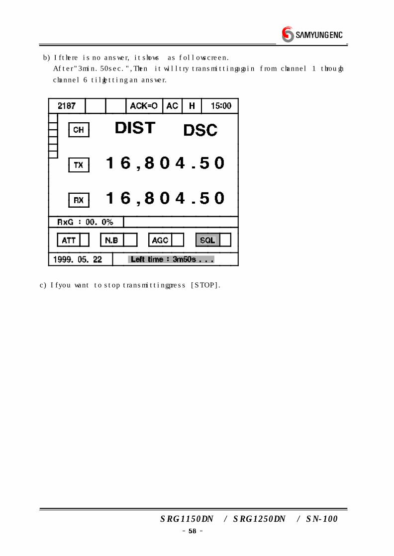
b) If there is no answer, it shows as follow screen.
After "3min. 50sec.", Then it will try transmitting again from channel 1 through
channel 6 till getting an answer.
c) If you want to stop transmitting, press [STOP].
SRG-1150DN / SRG-1250DN / SN-100
8. HOW TO USE PRINTER
8.1 DPU-414 PRINTER
(1) Caution when use printer
a) The printing paper used for the DPU-414 is a special kind of paper which turns
black by the thermochemistry reaction. Take as following precaution when using
the paper.
Store away from Hit, humidity, light
Dry your hands before handling the paper.
Do not rub the paper with any kind of hard or coarse materials.
Do not use organic adhesive on the paper. (Instead of that, water-based
starch adhesives or compound adhesive.)
Do not use adhesive tape on the paper. (However, using both sided tape is
possible.)
Do not allow the paper to remain in contact with polyvinyl chloride film for a
long time.
Do not leave the paper in contact with freshly coped giazo type or wet
process paper.
Do not allow the paper to come into contact with organic solvents.
b) Caution when operate printer
Check there is a paper in it before use.
Do not turn off while operation and turn off after PRINT HEAD is at HOME
POSITION.
Printer test function is built-in.
(2) Operation Panels
a) Power switch
: Switch on the turn this unit on. Printer head do going and returning once, the
paper is fed by one column.
On condition that main unit of SRG-1150DN/SRG-1250DN is power on.
b) FEED switch
: Press FEED switch when feed the paper out by force.
On pressing this switch once, it will be feed once and on pressing this switch
continuously, it will be kept feeding.
c) Cutter : Use for cutting the printer paper.
d) Exit of paper : it is the part where the paper is ejected through it.
SRG-1150DN / SRG-1250DN / SN-100
e) Paper cover : Store up the paper inside it.
(3) Usual operation
Check the main unit of SRG-1150DN/SRG-1250DN is turned on.
If power on, it is able to print TX/RX DSC MESSAGE and DATA from
SRG-1150DN/SRG1250DN automatically.
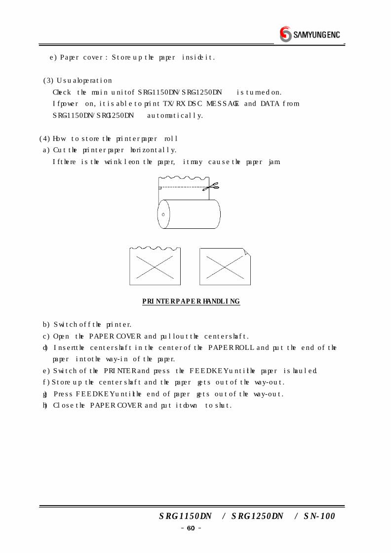
(4) How to store the printer paper roll
a) Cut the printer paper horizontally.
If there is the wrinkle on the paper, it may cause the paper jam.
PRINTER PAPER HANDLING
b) Switch off the printer.
c) Open the PAPER COVER and pull out the center shaft.
d) Insert the center shaft in the center of the PAPER ROLL and put the end of the
paper into the way-in of the paper.
e) Switch of the PRINTER and press the FEED KEY until the paper is hauled.
f) Store up the center shaft and the paper gets out of the way-out.
g) Press FEED KEY until the end of paper gets out of the way-out.
h) Close the PAPER COVER and put it down to shut.
SRG-1150DN / SRG-1250DN / SN-100
8.2 OKI PRINTER
(1) IMPORTANT
a) The wires this mains lead are coloured in accordance with the following code:
GREEN AND YELLOW EARTH
BLUE NEUTRAL
BROWN LIVE
As the colors of the wires in the mais lead of this apparatus may not correspond
with the coloured markings identifying the terminals in your plug PROCEED AS
FOLLOWS:
The wire coloured GREEN AND YELLOW must be connected to the terminal in the
plug marked with the letter E or by the safety earth symbol or coloured GREEN or
GREEN AND YELLOW . The wire coloured BROWN must be connected to the
terminal marked with the letter L or coloured RED. The wire coloured BLUE must
be connected to the terminal marked with the letter N or coloured BLACK.
※ WARNING : THIS APPARATUS MUST BE EARTHED
b) Ensure that your equipment is connected correctly.
If you are in any doubt consult a qualified electrician. Operating your Printer.
Buttons, Levers and Indicators.
Before using your printer, it is worth familiarizing yourself with the buttons, levers
and indicators on the printer and to understand the various methods of loading
paper.
The front panel of the printer has six buttons. Also there are indicator lights that
show the status of the printer, mode and pitch selected.
c) POWER Indicator : Indicates that the printer power is turned ON .
d) SELECT Button
: Pressing this button after the printer power is On places the printer in deselect
mode the computer cannot communicate with the printer.
To return to select mode, simply press this button again.
Pressing this button also stops the self test. In is also used in enter into
HEX-dump mode: turn the printer ON while holding down the SELECT and FORM
FEED buttons.
Hex mode generates data rather than test and a sample is shown below.
To terminate this mode, switch the printer off and on again.
SRG-1150DN / SRG-1250DN / SN-100
Switching on the printer while holding down th SELECT and Line Feed buttons will
generate a rolling ASCII character display, Reset the printer to terminate.
A sample is shown below.
e) TOF button
: To set the first position on each page (Top of Form), deselect the printer when
the print head is in the desired position.
You can also select 17.1 character per inch printing by holding this button down
when turning printer power ON.
f) SELECT Indicator
: Works together with the SELECT button. Lights when the printer is selected
(ready to receive data from the computer).
The indicator is not lit when th printer is deselected or during self tests.
If an abnormal status is detected during the self test the indicator flashes.
g) FORM FEED Button
: To advance the paper to the nest page (Top Of Form), press this button while
the printer is deselected.
You can also select NLQ (Near Letter Quality) with this button. Just hold down the
FORM FEED button while switching on the printer.
h) ALARM Indicator
: Lights when paper supply is low or exhausted (unless you use the
command to disable the alarm). Printing stops until the paper supply is
replenished.
It is also lit when a jam is detected using th CSF. The light flashes when high
temperatures are detected in th print head and space motor.
Allow th printer to cool down before re-using.
I) LINE FEED Button
: If you want to advance the paper one line, press this button while the printer is
deselected. ADEMO page print can be generated by switching on the printer and
holding down the Line Feed Button. This print out illustrates the various styles of
printing available from the ML184Turbo.
Once printed, the printer automatically reverts to 10cpi Utility mode.
An example of the DEMO PAGE IS ON THE NEXT PAGE.
SRG-1150DN / SRG-1250DN / SN-100
j) PITCH Button
: This button allows you to manually select the character pitch.
The appropriate lamp glows upon selection. The lamps also light as software
changes, for example, normal to condensed, are implemented.
k) MODE Button
: Similar function to above, but this refers to the print quality selected:
NLQ, Utility or High Speed Draft. The levers on the printer allow you to adjust the
paper.
l) PAPER LOCK / RELEASE LEVER
: Open (slide forwards) for inserting paper, and adjusting paper, and when using
tractor fed computer paper. Close (slide back) for use with roll paper and for
single sheets.
m) PAPER GAP ADJUSTMENT
: Slide towards the back of the printer when inserting single sheets, and away
when using multi-part paper.
(2) PAPER LOADING
Bottom Feed Paper Loading
a) Place the printer on a slotted printer stand, carefully aligning the slot in the
stand with the opening in the base of the printer.
b) Place the box of paper under the printer stand.
c) remove the access cover and lift the column indicator bar.
d) Open the paper release lever.
e) Insert the first sheet of paper through the opening in the bottom of the printer.
f) Slide the paper up until it appears in front of the platen.
g) Lower the column indicator bar.
h) Close the paper release lever.
I) Use the platen knob to advance the paper to the first printing line.
j) Replace the access cover.
Rear Fed Paper Loading
a) Put the printer on a desk or table.
b) Place the box of paper behind the printer.
c) Remove the access cover and lift the column indicator bar.
d) Open the paper release lever.
e) Insert the first sheet of paper in the paper guides.
SRG-1150DN / SRG-1250DN / SN-100
f) Push the paper in just enough so that its sprocket holes engage the sprocket
pins located on the platen ends.
g) Turn the platen knob to advance the paper until it appears in front of the
platen.
h) Lower the column indicator bar.
I) Close the paper release lever.
j) Use the platen knob to advance the paper to the first printing line.
k) Replace the access cover.
SRG-1150DN / SRG-1250DN / SN-100
9. HOW TO USE SD-250(ALARM BOX)
9.1 DISTRESS TRANSMITTING
1. If you press 'Distress Key'(red button) for 3 sec., it alarm for 3 sec.
After that, the red light is turned on with bip- sound.
While Distress Key is blinking, transmitting is started to work and location of
disaster, time, ship's ID are sent to DSC 6CH in order.
If there is no answer, it do sending till getting an answer through CH1 to CH6.
2. If you make transmitting stop, press 'Reset key'.
※ If distress signal is sent by mistakes, contact to marine police or station, SAR.
9.2 IN CASE OF RECEIVING DISTRESS SIGNAL
1. Distress LED blinks and sounds 'bip'.
Check contents displayed on the screen and press Reset key to stop.
9.3 OPERATION BY DC POWER (BATTERY)
1. If AC power is turned off, POWER LED will started blinking with "bip-" sound.
When bip is stoped, press Reset Key.
2. POWER LED keep blinking while the equipment is operated by DC power.
SRG-1150DN / SRG-1250DN / SN-100
10. EXPLANATION OF CIRCUIT
10.1 OVERVIEW OF SRG-1150DN/SRG-1250DN
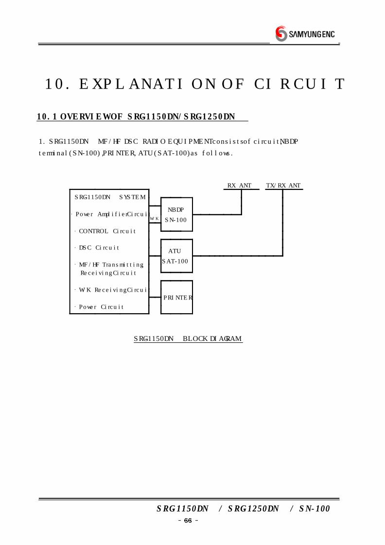
1. SRG-1150DN MF/HF DSC RADIO EQUIPMENT consists of circuit, NBDP
terminal(SN-100), PRINTER, ATU(SAT-100) as follows.
RX ANT TX/RX ANT
SRG-1150DN SYSTEM
Power Amplifier Circuit
CONTROL Circuit
DSC Circuit
MF/HF Transmitting,
Receiving Circuit
W/K Receiving Circuit
Power Circuit
NBDP
SN-100W/K
ATU
SAT-100
PRINTER
SRG-1150DN BLOCK DIAGRAM
SRG-1150DN / SRG-1250DN / SN-100
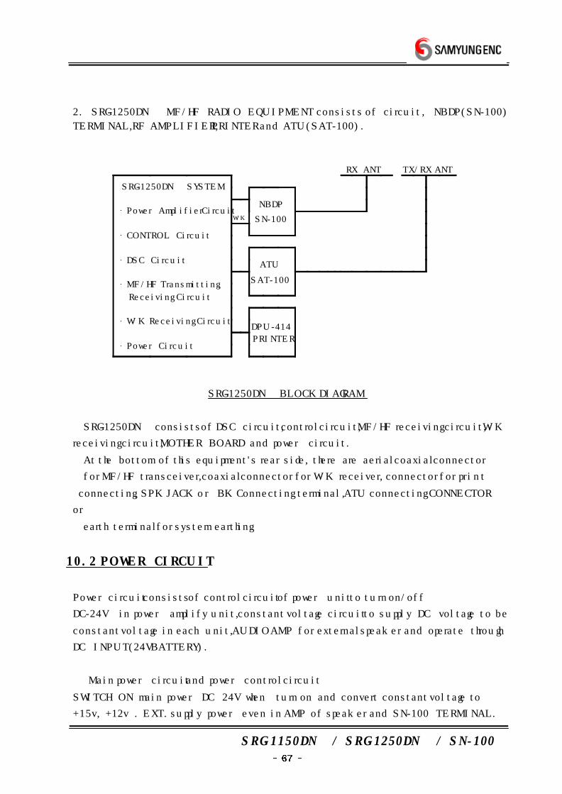
2. SRG-1250DN MF/HF RADIO EQUIPMENT consists of circuit , NBDP(SN-100)
TERMINAL, RF AMPLIFIER, PRINTER and ATU(SAT-100).
RX ANT TX/RX ANT
SRG-1250DN SYSTEM
Power Amplifier Circuit
CONTROL Circuit
DSC Circuit
MF/HF Transmitting,
Receiving Circuit
W/K Receiving Circuit
Power Circuit
NBDP
SN-100W/K
ATU
SAT-100
DPU-414
PRINTER
SRG-1250DN BLOCK DIAGRAM
SRG-1250DN consists of DSC circuit, control circuit, MF/HF receiving circuit, W/K
receiving circuit, MOTHER BOARD and power circuit.
At the bottom of this equipment's rear side, there are aerial coaxial connector
for MF/HF transceiver, coaxial connector for W/K receiver, connector for print
connecting, SPK JACK or BK Connecting terminal, ATU connecting CONNECTOR
or
earth terminal for system earthing.
10.2 POWER CIRCUIT
Power circuit consists of control circuit of power unit to turn on/off
DC-24V in power amplify unit, constant voltage circuit to supply DC voltage to be
constant voltage in each unit, AUDIO AMP for external speaker and operate through
DC INPUT(24V BATTERY).
⑴ Main power circuit and power control circuit
SWITCH ON main power DC 24V when turn on and convert constant voltage to
+15v, +12v . EXT. supply power even in AMP of speaker and SN-100 TERMINAL.

SRG-1150DN / SRG-1250DN / SN-100
(if NBDP TERMINAL is set.)
⑵ PROTECTION and ALARM
In overload voltage +32v, make power off and built circuit to prevent conversing
voltage not to demage equipment even in conversing voltage.
10.3 TRANSMITTING CIRCUIT
Bias voltage operate and maintain fitting voltage to press PTT(transmitting switch)
installed in HAND MIC and virus voltage even in output amp for excitation is
supplied and receive sound-input from MIC installed and after amplify audio-input in
AF
AMP(T-452 Q34, Q36), in BALANCE MODULATION, mixed with BFO and in SSB
FILTER(XL2) filter low frequency part.
So, this signal is mixed in 49MHZ LOCAL and IC3 and amplify in 49MHZ+IF=2'nd
IF AMP(Q29).
This signal pass 49.455MHZ FILTER and is mixed in FC+49.455MHZ LOCAL and
IC4 is amplify in RF AMP(Q31,Q32) and pass LOW PASS FILTER.
This signal go to external RF AMPLIFIER and pass TX FILTER(T-551) and go to
POWER SPLITER(T-516_1) and pass T1,T2 and is separated as PWR AMP A(T-514)
and PWR AMP B(T-514).
This signal go to TX PWR CONBINER(T-516_2) and is combined and after go to
DSC TX FILTER(T-517) and amplify, in the selected TX LOW PASS FILTER, remove
spurious and pass antenna terminal and go to ATU and match transmitting
frequency and antenna frequency and transmit through antenna.
10.4 MF/HF RECEIVING CIRCUIT
Receiving signal in whip antenna pass band filter and after filter, amplify in
ultrashort amplifier T-454(Q13, Q14) and in 1‘st MIXER, fC+49.455MHZ LOCAL and
BALANCE MIXER and make IF 49.455MHZ.
This signal pass 455MHZ FILTER to become filtering and in amplifier Q9, amplify
and be balance mixed in 2‘nd LOCAL 49MHZ and 2’nd MIXER Q7, Q8 and make
455KHZ IF.
This signal become filtering through J3E(XL2), H3E(XL1) FILTER according to
MODE.
Again, amplify in Q1,IC6 and mix SSB and H3E in IC7.
SRG-1150DN / SRG-1250DN / SN-100
Mixed signal is divided to 3 species as follows.
① amplify for inner speaker audio.
② amplify for outer speaker audio.
③ FSK MODEM (DSC signal mix)
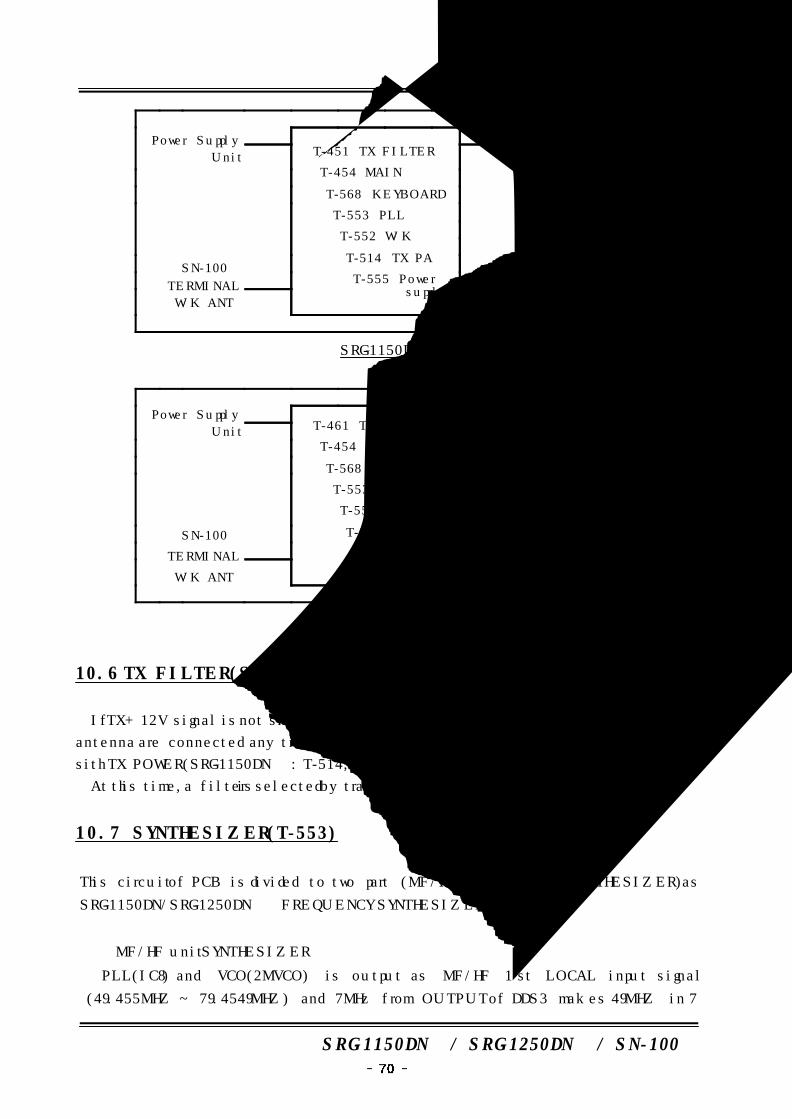
10.5 MOTHER BOARD(T-570)
Function of Mother Board (T-570) is connecting PCB
T-451(SRG-1150DN TX FILTER)/ T-461(SRG-1250DN TX FILTER),
T-454(TX/RX EXCITER),
T-557(CONTROL), T-553(PLL SYNTHESIZE),
T-555(POWER SUPPLY UNIT),
T-552(W/K RECEIVER),
T-514(SRG-1150DN TX POWER AMP)/T-524(SRG-1250DN TX POWER AMP)
each other.
BK signal given from external pass PHOTO COUPLER to separate union earthing
POLE from receiver inner circuit and supply in BK control circuit.
BK controling circuit control BK RELAY of input unit of high frequency and AGC
circuit and protect receiver from over input.
Simultaneously, have a muting receiving circuit.
Moreover, it connect several connectors at rear side and do switching power
supply of RX and TX.
a) This circuit board incorporate through most circuit board to consist
of main unit organically and electronically and operate.
b) In this circuit board, connecting of front, real and external is carried on
and each connector pass filter circuit for noise-clear and is connected
c) Each circuit board connected by this circuit board arranged connectors
mechanically not to incorporate in wrong-position.
SCHEMATIC IS AS FOLLOW.
SRG-1150DN / SRG-1250DN / SN-100
Power Supply
Unit T-451 TX FILTER
T-454 MAIN
T-568 KEYBOARD
T-553 PLL
T-552 W/K
T-514 TX PA
T-555 Power supply
MF/HF ANT
SN-100
TERMINAL
W/K ANT
Input & Output
External signal
SRG-1150DN
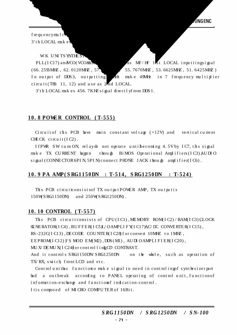
Power Supply
Unit T-461 TX FILTER
T-454 MAIN
T-568 KEYBOARD
T-553 PLL
T-552 W/K
T-524 TX PA
T-555 Power supply
MF/HF ANT
SN-100
TERMINAL
W/K ANT
Input & Output
External signal
SRG-1250DN
10.6 TX FILTER(SRG-1150DN : T-451, SRG-1250DN : T-461)
If TX+ 12V signal is not showed in the PCB circuit, the main PCB(T-454) and
antenna are connected any time. And if Tx+ signal is showed, antenna is connected
sith TX POWER(SRG-1150DN : T-514, SRG-1250DN : T-524) through FILTER circuit.
At this time, a filter is selected by transmitting frequency.
10.7 SYNTHESIZER (T-553)
This circuit of PCB is divided to two part (MF/HF unit and W/K SYNTHESIZER) as
SRG-1150DN/SRG-1250DN FREQUENCY SYNTHESIZER.
① MF/HF unit SYNTHESIZER
PLL(IC8) and VCO(2MVCO) is output as MF/HF 1‘st LOCAL input signal
(49.455MHZ ~ 79.4549MHZ) and 7MHz from OUTPUT of DDS3 makes 49MHZ in 7
SRG-1150DN / SRG-1250DN / SN-100
frequency multiplier circuit(T7, 9, 11, 12) and use as 2‘nd LOCAL.
3'th LOCAL makes 456.4KHZ±125HZ signal directly from DDSI.
② W/K UNIT SYNTHESIZER
PLL(IC17)and VCO(VCO&) is output as MF/HF 1‘st LOCAL inputting signal
(66.2595MHZ, 62.0120MHZ, 57.8695MHZ, 55.7670MHZ, 53.6625MHZ, 51.6425MHZ)
In output of DDS3, outputting 7 MHz make 49MHz in 7 frequency multiplier
circuit(T8. 9. 11, 12) and use as 2‘nd LOCAL.
3'th LOCAL makes 456.7KHZ signal directly from DDS1.
10.8 POWER CONTROL (T-555)
Circuit of this PCB have main constant voltage (+12V) and vertical current
CHECK circuit(IC2).
If PWR SW turn ON, relay do not operate until becoming 4.5V by IC7, this signal
make TX CURRENT happen through BiMOS Operational Amplifiers(IC3), AUDIO
signal(CONNECTOR 6PIN, 5PIN) connect PHONE JACK through amplifier(IC6).
10.9 PA AMP(SRG-1150DN : T-514, SRG-1250DN : T-524)
This PCB circuit consists of TX output POWER AMP, TX output is
150W(SRG-1150DN) and 250W(SRG-1250DN).
10.10 CONTROL (T-557)
This PCB circuit consists of CPU(IC1), MEMORY ROM(IC2)/RAM(IC3), CLOCK
GENERATOR(IC4), BUFFER(IC5), I/O AMPLIFY(IC17), AC/DC CONVERTER(IC15),
RS-232C(IC13), DECODE COUNTER(IC28) for convert 10MHZ to 1MHZ,
EEPROM(IC12), FS MOD EM(M2), DDS(M1), AUDIO AMPLIFIER(IC20),
MUX/DEMUX(IC24) for controlling LCD CONTRAST.
And it controls SRG-1150DN/SRG-1250DN on the whole, such as operation of
TX/RX, switch, front LCD and etc.
Control unit has function to make signal to need in controling of synthesizer part
had a outbreak according to PANEL operating of control unit, function of
information-exchange and function of indication-control.
It is composed of MICRO COMPUTER of 16Bit.
SRG-1150DN / SRG-1250DN / SN-100
a) MICRO COMPUTER be set by operating PANEL and set synchronizing circuit
responded by receiving frequency (selecting channel).
And then, according to receiving frequency, set information setting frequency for
SYNTHESIZER or REF/BFO.
In addition, MICRO COMPUTER pass signal (LOCAL CONTROL) to indicate various
information(receiving frequency, receiving mode, band, width) set by operating
panel of controller unit and transmit in control unit.
Except this function, in case of interception of power or supply-cease, MICRO
COMPUTER control memory degaussing to be back-up by battery built.
Memory status before normal of power and in case of normal, possible to rebuild.
10.11 FRONT (T-568)
This PCB circuit is composed of switch, LED, voice, sensitivity modulator.
10.12 W/K RECEIVER UNIT(T-552)
Receiving method is 1st intermediate frequency(49.455MHz), DOUBLE-SUPER
HETERODYNE TYPE of 2nd intermediate frequency(455KHz).
All local signal of receiver is supplied from DIGITAL CONTROL FREQUENCY
SYNTHESIZER through PHASE LOCKED LOOP(PLL) system and direct system to
use 10MHz center oscillator(supplied from DTCXO : SSB GENERATOR circuit).
a) Receiving signal in ANTENNA terminal pass BK RELAY and input and voltage
protecting circuit and pass band-pass filter and is closing in DSC distress safety
frequency.
FILTER is separated from inner MICRO COMPUTER to response in receiving
CHANNEL.
b) Receiving signal to pass filter passes 35MHz low band passing-filter and amplify
by high-frequency amplifier of width band and is supplied in first mixture part.
First mixture part is balance type of gate earth and receiving signal is
converted to 49.455MHz of 1st intermediate frequency to mix with 1 signal
supplied from 49.455MHz to 79.45499MHz from SYNTHESIZER Converting output
pass CRYSTAL FILTER of center frequency 49MHz passing band about 15KHz
and amplify through 1st intermediate amplifier and is supplied in 2 mixture part.
Receiving signal as 2 mixture part is mixed with 2 signal supplied from
SRG-1150DN / SRG-1250DN / SN-100
SYNTHESIZER unit and converted to 2nd frequency 455KHz.
c) Receiving signal amplified through 2 intermediate frequency amplify is supplied
from AGC circuit and mixing circuit.
AGC voltage picked up from AGC circuit be feed back in 2 step of amplifier of
1 intermediate frequency and amplifier of 2 intermediate frequency and control
benefit of each amplifier.
Receiving circuit supplied from mixture circuit is mixed with BFO supplied from
SYNTHESIZER circuit and mixed.
Mixing output is supplied from DSC mixture unit.
*** DSC MIXING UNIT
DSC mixing unit is to pick up DOT PATTERN moved in DSC distress alarm signal
and is composed of FILTER circuit, mixing circuit or micro processor for DOT PATTE
RN JUDGE.
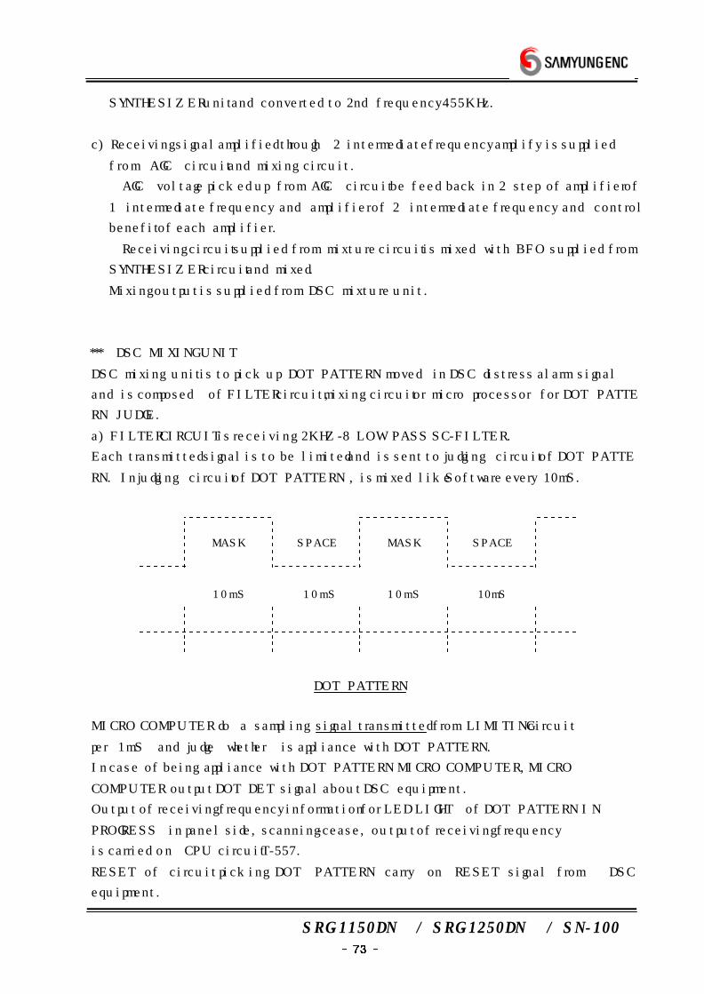
a) FILTER CIRCUIT is receiving 2KHZ-8 LOW PASS SC-FILTER.
Each transmitted signal is to be limited and is sent to judging circuit of DOT PATTE
RN. In judging circuit of DOT PATTERN , is mixed like Software every 10mS.
MASK SPACE MASK SPACE
10mS 10mS 10mS 10mS
DOT PATTERN
MICRO COMPUTER do a sampling signal transmitted from LIMITING circuit
per 1mS and judge whether is appliance with DOT PATTERN.
In case of being appliance with DOT PATTERN MICRO COMPUTER, MICRO
COMPUTER output DOT DET signal about DSC equipment.
Output of receiving frequency information for LED LIGHT of DOT PATTERN IN
PROGRESS in panel side, scanning-cease, output of receiving frequency
is carried on CPU circuit T-557.
RESET of circuit picking DOT PATTERN carry on RESET signal from DSC
equipment.
SRG-1150DN / SRG-1250DN / SN-100
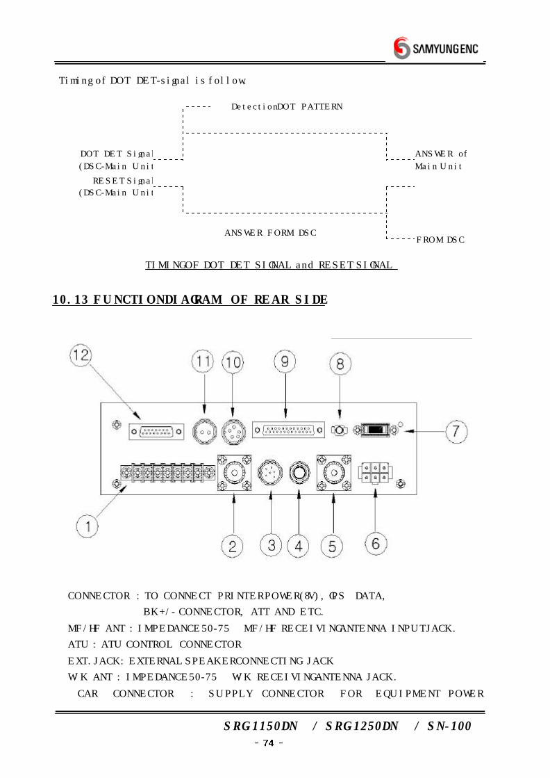
Timing of DOT DET-signal is follow.
Detection DOT PATTERN
DOT DET Signal
(DSC-Main Unit)
ANSWER of
Main Unit
RESET Signal
(DSC-Main Unit)
ANSWER FORM DSCFROM DSC
TIMING OF DOT DET SIGNAL and RESET SIGNAL
10.13 FUNCTION DIAGRAM OF REAR SIDE
① CONNECTOR : TO CONNECT PRINTER POWER(8V), GPS DATA,
BK+/- CONNECTOR, ATT AND ETC.
② MF/HF ANT : IMPEDANCE 50-75Ω MF/HF RECEIVING ANTENNA INPUT JACK.
③ ATU : ATU CONTROL CONNECTOR
④ EXT.JACK : EXTERNAL SPEAKER CONNECTING JACK
⑤ W/K ANT : IMPEDANCE 50-75Ω W/K RECEIVING ANTENNA JACK.
⑥ CAR CONNECTOR : SUPPLY CONNECTOR FOR EQUIPMENT POWER
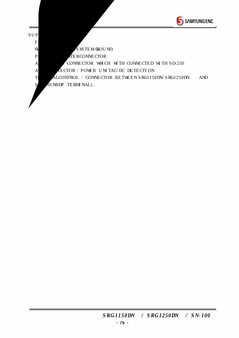
SRG-1150DN / SRG-1250DN / SN-100
SUPPLY(+24V).
⑦ FUSE : 30A FUSE
⑧ GND : RECEIVER SYSTEM GROUND.
⑨ PRINTER : PRINTER CONNECTOR
⑩ ALARM BOX : CONNECTOR WHICH WITH CONNECTED WITH SD-250
⑪ AC/DC DETECTOR : POWER UNIT AC/DC DETECTION
⑫ TERMINAL CONTROL : CONNECTOR BETWEEN SRG-1150DN/SRG-1250DN AND
SN-100(NBDP TERMINAL).
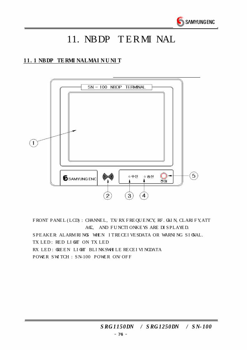
SRG-1150DN / SRG-1250DN / SN-100
11. NBDP TERMINAL
11.1 NBDP TERMINAL MAIN UNIT
① FRONT PANEL (LCD) : CHANNEL, TX/RX FREQUENCY, RF.GAIN, CLARIFY, ATT
AGC, AND FUNCTION KEYS ARE DISPLAYED.
② SPEAKER : ALARM RINGS WHEN IT RECEIVES DATA OR WARNING SIGNAL.
③ TX LED : RED LIGHT ON TX LED
④ RX LED : GREEN LIGHT BLINKS WHILE RECEIVING DATA
⑤ POWER SWITCH : SN-100 POWER ON/OFF
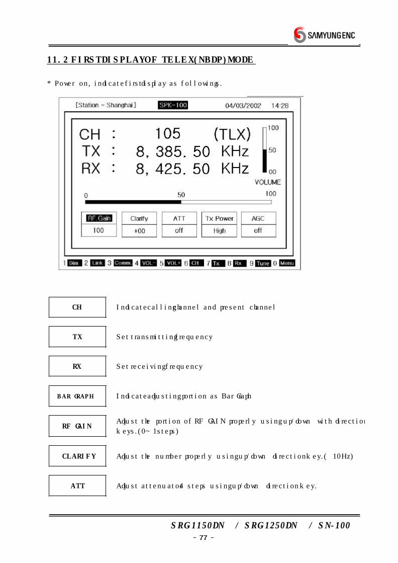
SRG-1150DN / SRG-1250DN / SN-100
11.2 FIRST DISPLAY OF TELEX(NBDP) MODE
* Power on, indicate first display as followings.
CH Indicate calling channel and present channel
TX Set transmitting frequency
RX Set receiving frequency
BAR GRAPH Indicate adjusting portion as Bar Graph
RF GAINAdjust the portion of RF GAIN properly using up/down with direction
keys. (0~1steps)
CLARIFY Adjust the number properly using up/down direction key. (±10Hz)
ATT Adjust attenuator 4 steps using up/down direction key.
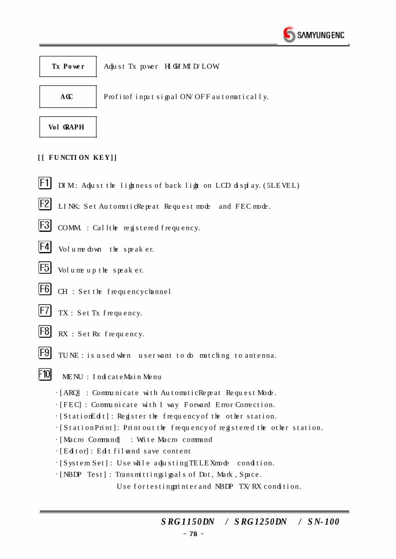
SRG-1150DN / SRG-1250DN / SN-100
Tx Power Adjust Tx power HIGH/MID/LOW.
AGC Profit of input signal ON/OFF automatically.
Vol GRAPH
[[ FUNCTION KEY ]]
DIM : Adjust the lightness of back light on LCD display.(5 LEVEL)
LINK : Set Automatic Repeat Request mode and FEC mode.
COMM. : Call the registered frequency.
Volume down the speaker.
Volume up the speaker.
CH : Set the frequency channel
TX : Set Tx frequency.
RX : Set Rx frequency.
TUNE : is used when user want to do matching to antenna.
MENU : Indicate Main Menu
[ARQ] : Communicate with Automatic Repeat Request Mode.
[FEC] : Communicate with 1 way Forward Error Correction.
[Station Edit] : Register the frequency of the other station.
[Station Print] : Print out the frequency of registered the other station.
[Macro Command] : Write Macro command
[Editor] : Edit file and save content
[System Set] : Use while adjusting TELEX mode condition.
[NBDP Test] : Transmitting signals of Dot, Mark, Space.
Use for testing printer and NBDP TX/RX condition.
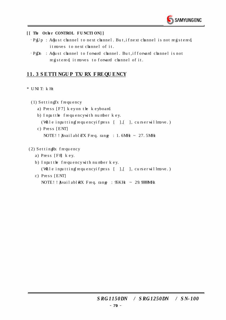
SRG-1150DN / SRG-1250DN / SN-100
[[ The Other CONTROL FUNCTION ]]
PgUp : Adjust channel to next channel. But, if next channel is not registered,
it moves to next channel of it.
PgDn : Adjust channel to forward channel. But, if forward channel is not
registered, it moves to forward channel of it.
11.3 SETTING UP TX/RX FREQUENCY
* UNIT : kHz
(1) Setting Tx frequency
a) Press [F7] key on the keyboard.
b) Input the frequency with number key.
(While inputting frequency if press [→],[←], curser will move.)
c) Press [ENT]
NOTE!!) Available TX Freq. range : 1.6MHz ~ 27.5MHz
(2) Setting Rx frequency
a) Press [F8] key.
b) Input the frequency with number key.
(While inputting frequency if press [→],[←], curser will move.)
c) Press [ENT]
NOTE!!) Available RX Freq. range : 95KHz ~ 29.99999MHz
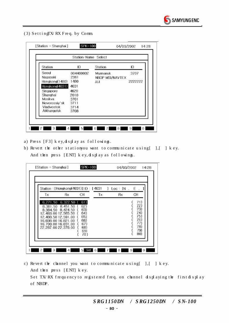
SRG-1150DN / SRG-1250DN / SN-100
(3) Setting TX/RX Freq. by Comm.
a) Press [F3] key, display as followings.
b) Revert the other station you want to communicate using [→],[←] key.
And then press [ENT] key, display as followings.
c) Revert the channel you want to communicate using [→],[←] key.
And then press [ENT] key.
Set TX/RX frequency to registered freq. on channel displaying the first display
of NBDP.
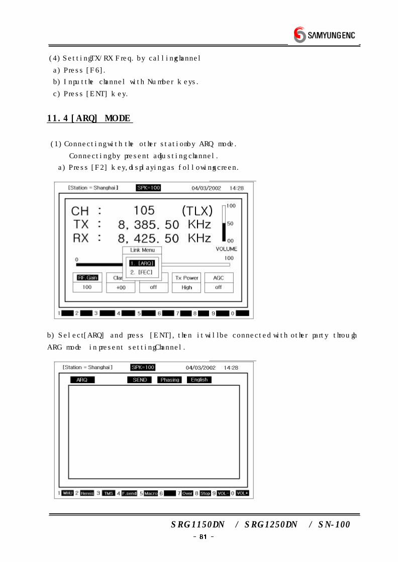
SRG-1150DN / SRG-1250DN / SN-100
(4) Setting TX/RX Freq. by calling channel
a) Press [F6].
b) Input the channel with Number keys.
c) Press [ENT] key.
11.4 [ARQ] MODE
(1) Connecting with the other station by ARQ mode.
※ Connecting by present adjusting channel.
a) Press [F2] key, displaying as following screen.
b) Select [ARQ] and press [ENT], then it will be connected with other party through
ARG mode in present setting Channel.
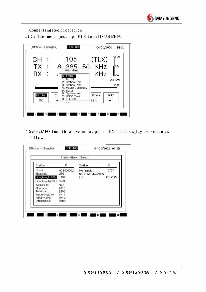
SRG-1150DN / SRG-1250DN / SN-100
※ Connecting specific station
a) Call the menu pressing [F10] to call SUB MENU.
b) Select ARQ from the above menu, press [ENT] then display the screen as
follow.
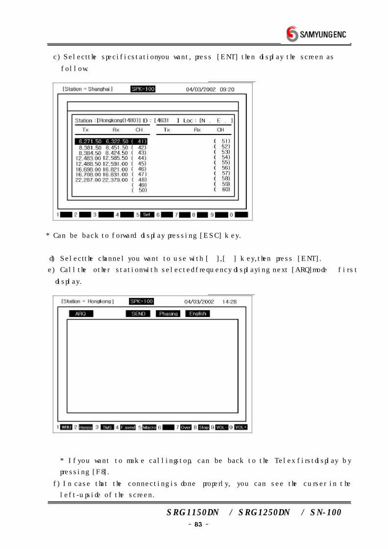
SRG-1150DN / SRG-1250DN / SN-100
c) Select the specific station you want, press [ENT] then display the screen as
follow.
* Can be back to forward display pressing [ESC] key.
d) Select the channel you want to use with [→],[←] key, then press [ENT].
e) Call the other station with selected frequency displaying next [ARQ]mode first
display.
* If you want to make calling stop, can be back to the Telex first display by
pressing [F8].
f) In case that the connecting is done properly, you can see the curser in the
left-up side of the screen.
SRG-1150DN / SRG-1250DN / SN-100
(2) Communication in ARQ mode
* After done above (1), communicate with using below functions.
a) As long as you can connect with the other station in ARQ mode, above screen
is displayed. You can keep communicating in this condition.
b) After typing the message with keyboard, press [ENT] key.
* Back space - delete one character on the left.
Before you press [ENT] key, transmitting is not complete.
c) Press function key to use each function.
d) Can transmit Macro Command in written in [F5].
(3) Usable keys in ARQ mode
* The usable characters
ABCDEFGHIJKLMNOPQRSTUVWXYZ1234567890
-?().,'=/+abcdefghijklmnopqrstuvwxyz
* Back space - Delete one character on the left.
* Enter - Send one line.
* Shift(on the left) + Space - Convert language. (English, Russian)
NOTE!!) It is possible while the present language is Russian only.
* F1 : 'WHU' - Demand Answer back code of the other station.
* F2 : 'Hereis' - Transmit Answer back code of yourself.
* F3 : 'TMS' - Transmit the present time.
* F4 : 'F.Send' - Transmit the file written in edit mode. (Refer to (4) TX of file)
* F5 : 'Macro' - Transmit Macro Command
* F7 : 'Over' - Convert the direction of transmitting the message.
* F8 : 'Stop' - Stop communication.
* F9 : 'VOL-' - Volume down
* F 10 : 'VOL+' - Volume up
(4) Transmitting file
* After done above (1), follow the operation as below.
a) Press [F4] and after selecting the file using [→],[←] key, press [ENT].
b) Can be transmitted displaying the contents of the file on the screen.
* Pressing [F8] key is able to stop transmitting .
(5) Transmitting of Macro Command
* After done (1), follow the operation below.
a) Press [F5] and after selecting the command, press [ENT].
c) Can be transmitted displaying contents of Command on the screen.
* Pressing [F8] is able to stop transmitting.
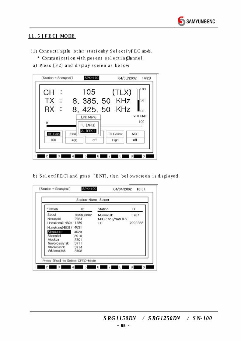
SRG-1150DN / SRG-1250DN / SN-100
11.5 [FEC] MODE
(1) Connecting the other station by Selective FEC mode.
* Communication with present selecting Channel.
a) Press [F2] and display screen as below.
b) Select [FEC] and press [ENT], then below screen is displayed.
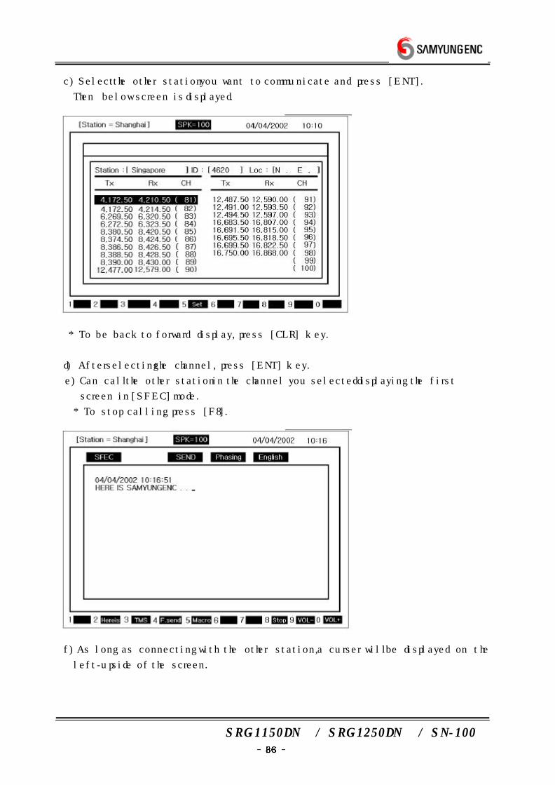
SRG-1150DN / SRG-1250DN / SN-100
c) Select the other station you want to communicate and press [ENT].
Then below screen is displayed.
* To be back to forward display, press [CLR] key.
d) After selecting the channel, press [ENT] key.
e) Can call the other station in the channel you selected displaying the first
screen in [SFEC] mode.
* To stop calling , press [F8].
f) As long as connecting with the other station, a curser will be displayed on the
left-up side of the screen.
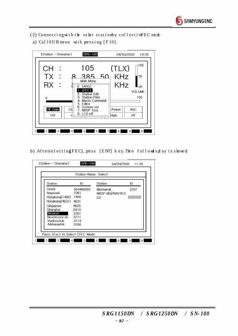
SRG-1150DN / SRG-1250DN / SN-100
(2) Connecting with the other station by collective FEC mode
a) Call SUB menu with pressing [F10].
b) After selecting [FEC], press [ENT] key. Then follow display is showed.
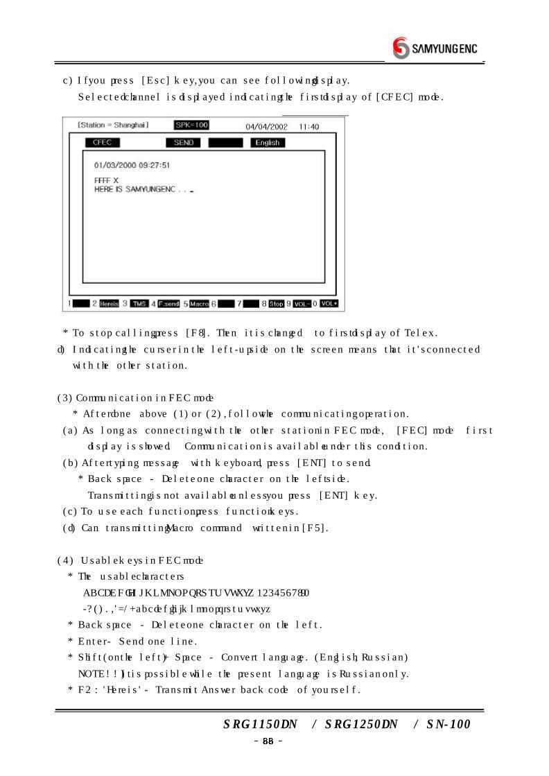
SRG-1150DN / SRG-1250DN / SN-100
c) If you press [Esc] key, you can see following display.
Selected channel is displayed indicating the first display of [CFEC] mode.
* To stop calling, press [F8]. Then it is changed to first display of Telex .
d) Indicating the curser in the left-up side on the screen means that it's connected
with the other station.
(3) Communication in FEC mode
* After done above (1) or (2), follow the communicating operation.
(a) As long as connecting with the other station in FEC mode, [FEC] mode first
display is showed. Communication is available under this condition.
(b) After typing message with keyboard, press [ENT] to send.
* Back space - Delete one character on the left side.
Transmitting is not available unless you press [ENT] key.
(c) To use each function, press function keys.
(d) Can transmitting Macro command written in [F5].
(4) Usable keys in FEC mode
* The usable characters
ABCDEFGHIJKLMNOPQRSTUVWXYZ1234567890
-?().,'=/+abcdefghijklmnopqrstuvwxyz
* Back space - Delete one character on the left.
* Enter - Send one line.
* Shift(on the left) + Space - Convert language. (English, Russian)
NOTE!!) It is possible while the present language is Russian only.
* F2 : 'Hereis' - Transmit Answer back code of yourself.
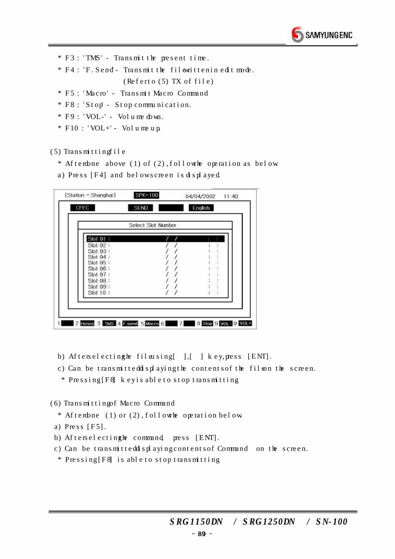
SRG-1150DN / SRG-1250DN / SN-100
* F3 : 'TMS' - Transmit the present time.
* F4 : 'F.Send' - Transmit the file written in edit mode.
(Refer to (5) TX of file)
* F5 : 'Macro' - Transmit Macro Command
* F8 : 'Stop' - Stop communication.
* F9 : 'VOL-' - Volume down.
* F10 : 'VOL+' - Volume up.
(5) Transmitting file
* After done above (1) of (2), follow the operation as below.
a) Press [F4] and below screen is displayed.
b) After selecting the file using [→],[←] key, press [ENT].
c) Can be transmitted displaying the contents of the file on the screen.
* Pressing [F8] key is able to stop transmitting .
(6) Transmitting of Macro Command
* After done (1) or (2), follow the operation below.
a) Press [F5].
b) After selecting the command, press [ENT].
c) Can be transmitted displaying contents of Command on the screen.
* Pressing [F8] is able to stop transmitting.
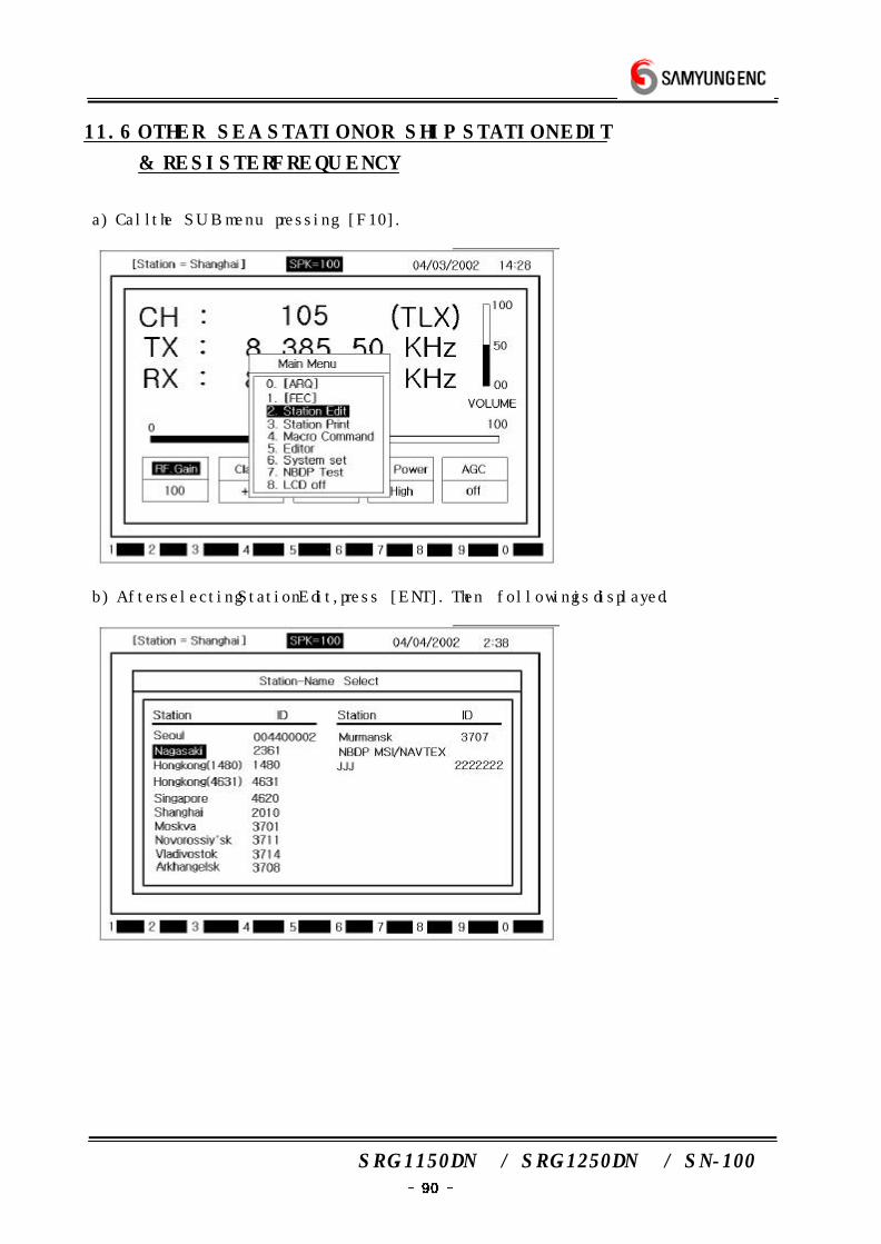
SRG-1150DN / SRG-1250DN / SN-100
11.6 OTHER SEA STATION OR SHIP STATION EDIT
& RESISTER FREQUENCY
a) Call the SUB menu pressing [F10].
b) After selecting Station Edit, press [ENT]. Then following is displayed.
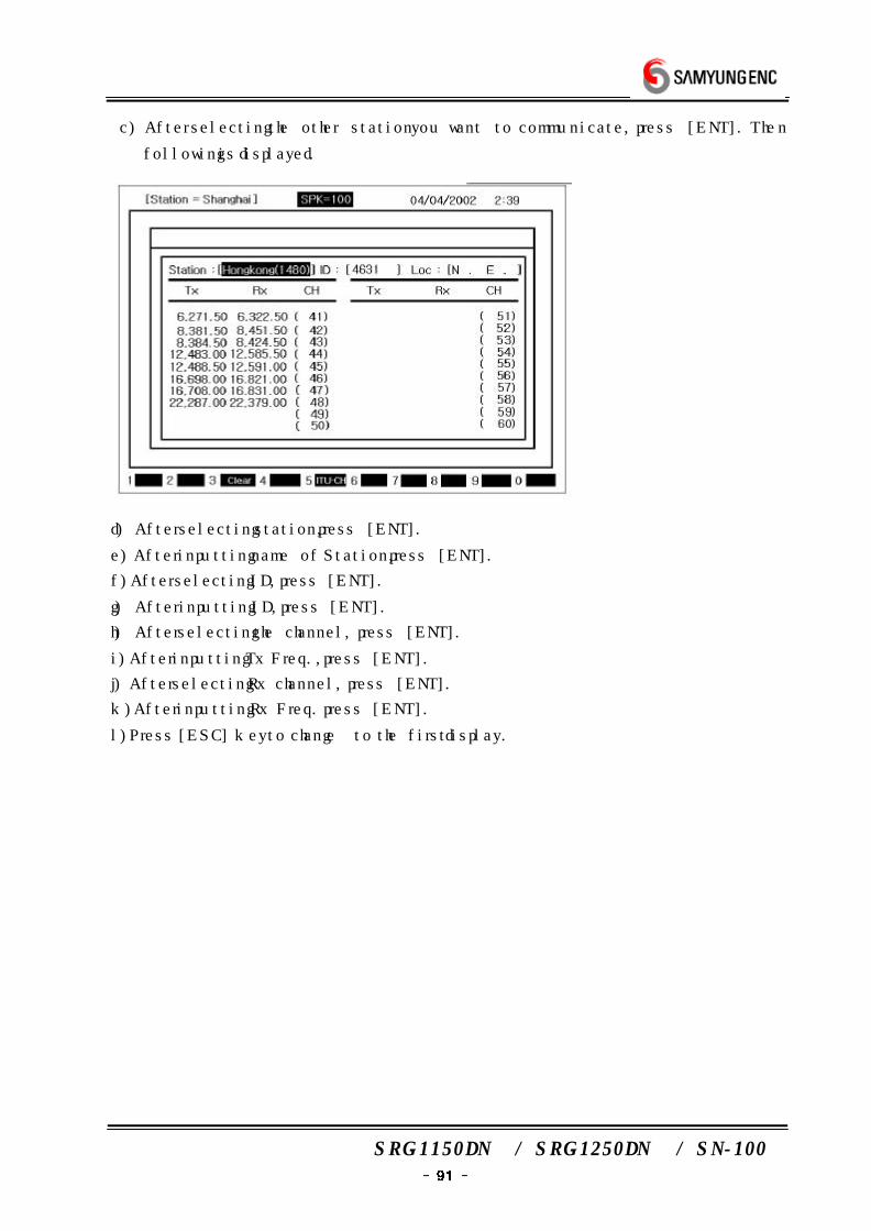
SRG-1150DN / SRG-1250DN / SN-100
c) After selecting the other station you want to communicate, press [ENT]. Then
following is displayed.
d) After selecting station, press [ENT].
e) After inputting name of Station, press [ENT].
f) After selecting ID, press [ENT].
g) After inputting ID, press [ENT].
h) After selecting the channel, press [ENT].
i) After inputting Tx Freq., press [ENT].
j) After selecting Rx channel, press [ENT].
k) After inputting Rx Freq. press [ENT].
l) Press [ESC] key to change to the first display.
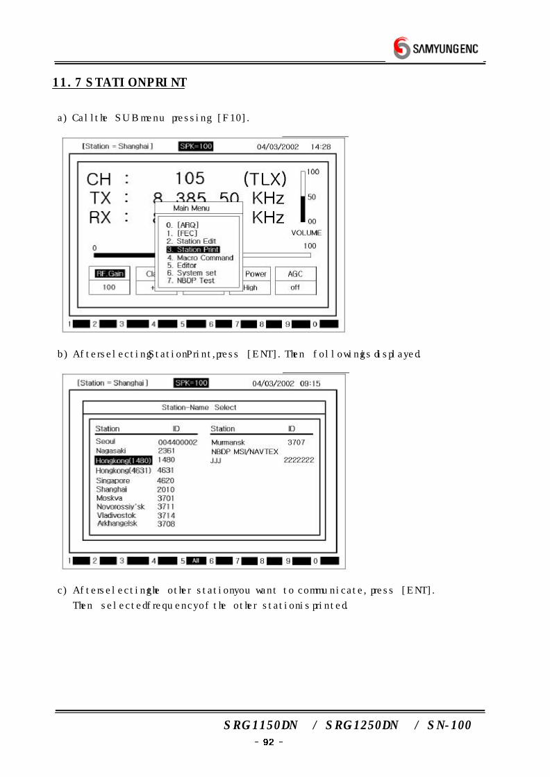
SRG-1150DN / SRG-1250DN / SN-100
11.7 STATION PRINT
a) Call the SUB menu pressing [F10].
b) After selecting Station Print, press [ENT]. Then following is displayed.
c) After selecting the other station you want to communicate, press [ENT].
Then selected frequency of the other station is printed.
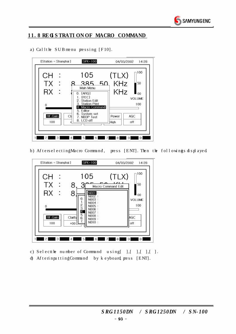
SRG-1150DN / SRG-1250DN / SN-100
11.8 REGISTRATION OF MACRO COMMAND
a) Call the SUB menu pressing [F10].
b) After selecting 'Macro Command', press [ENT]. Then the following is displayed.
c) Select the number of Command using [→],[←],[↓],[↑].
d) After inputting 'Command' by keyboard, press [ENT].
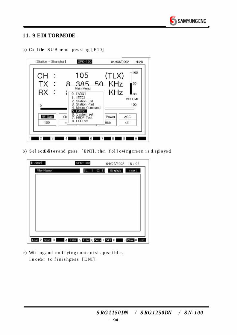
SRG-1150DN / SRG-1250DN / SN-100
11.9 EDITOR MODE
a) Call the SUB menu pressing [F10].
b) Select Editor and press [ENT], then following screen is displayed.
c) Writing and modifying contents is possible.
In order to finish, press [ENT].
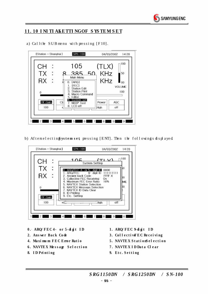
SRG-1150DN / SRG-1250DN / SN-100
11.10 INITIAL SETTING OF SYSTEM SET
a) Call the SUB menu with pressing [F10].
b) After selecting System set, pressing [ENT]. Then the following is displayed.
0. ARQ/FEC 4- or 5-digit ID 1. ARQ/FEC 9-digit ID
2. Answer Back Code 3. Collective FEC Receiving
4. Maximum FEC Error Ratio 5. NAVTEX Station Selection
6. NAVTEX Message Selection 7. NAVTEX ID Data Clear
8. ID Printing 9. Etc. Setting
SRG-1150DN / SRG-1250DN / SN-100
(1) Setting of ARQ/FEC 4- or 5-digit ID
* It is fixed when the equipment is set. It's impossible to change by user.
(2) Setting of ARQ/FEC 9-digit ID
* It is fixed when the equipment is set. It's impossible to change by user.
(3) Setting of Answer Back Code
* After done above (1), follow the operation below.
a) Select Answer Back Code.
b) After inputting Code, press [ENT] key.
(4) Setting of Collective FEC receiving
* It is fixed when the equipment is set. It's impossible to change by user.
a) Select Collective FEC Receiving.
b) If you press [ENT], turned On/Off by turns.
(5) Maximum FEC Error Ratio
* After doing as follow (1), operate the procedure as below.
a) Select Maximum FEC and press [ENT].
b) While receiving letters in FEC mode, if error ratio is over specific setting rate,
receiving is stoped automatically.
(Ex. If it is set as 30%, when error ratio is over 30% and receiving is stoped.)
Setting of ARQ/FEC 4- or 5-digit ID
* It is fixed when the equipment is set. It's impossible to change by user.
(6) Selecting NAVTEX STATION
* After doing as follow (1), operate the procedure as below.
a) Select NAVTEX station and press [ENT].
b) Able to set initial message of NAVTEX. (A~Z)
- O : indicate as initial message of NAVTEX.
- X : doesn't indicate as initial message of NAVTEX.
(7) Selecting NAVTEX message
* After doing as follow (1), operate the procedure as below.
a) Select Navtex Message and press [ENT].
b) Whether receiving message or not is selectable.
But, A, B, C, D are being received continuously.
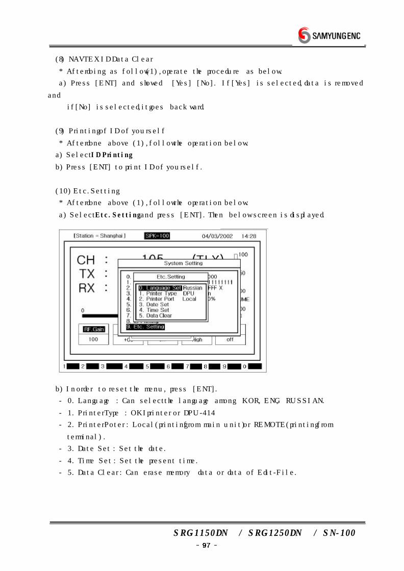
SRG-1150DN / SRG-1250DN / SN-100
(8) NAVTEX ID Data Clear
* After doing as follow (1), operate the procedure as below.
a) Press [ENT] and showed [Yes] [No]. If [Yes] is selected, data is removed
and
if [No] is selected, it goes backward.
(9) Printing of ID of yourself
* After done above (1), follow the operation below.
a) Select ID Printing .
b) Press [ENT] to print ID of yourself.
(10) Etc. Setting
* After done above (1), follow the operation below.
a) Select Etc. Setting and press [ENT]. Then below screen is displayed.
b) In order to reset the menu, press [ENT].
- 0. Language : Can select the language among KOR, ENG, RUSSIAN.
- 1. Printer Type : OKI printer or DPU-414
- 2. Printer Poter : Local(printing from main unit) or REMOTE(printing from
terminal).
- 3. Date Set : Set the date.
- 4. Time Set : Set the present time.
- 5. Data Clear : Can erase memory data or data of Edit-File.
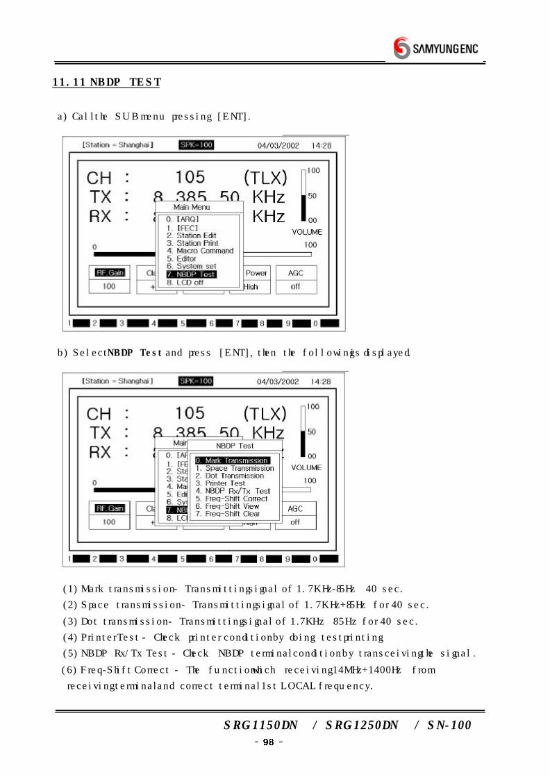
SRG-1150DN / SRG-1250DN / SN-100
11.11 NBDP TEST
a) Call the SUB menu pressing [ENT].
b) Select NBDP Test and press [ENT], then the following is displayed.
(1) Mark transmission - Transmitting signal of 1.7KHz-85Hz 40 sec.
(2) Space transmission - Transmitting signal of 1.7KHz+85Hz for 40 sec.
(3) Dot transmission - Transmitting signal of 1.7KHz±85Hz for 40 sec.
(4) Printer Test - Check printer condition by doing test printing.
(5) NBDP Rx/Tx Test - Check NBDP terminal condition by transceiving the signal.
(6) Freq-Shift Correct - The function which receiving 14MHz+1400Hz from
receiving terminal and correct terminal 1st LOCAL frequency.
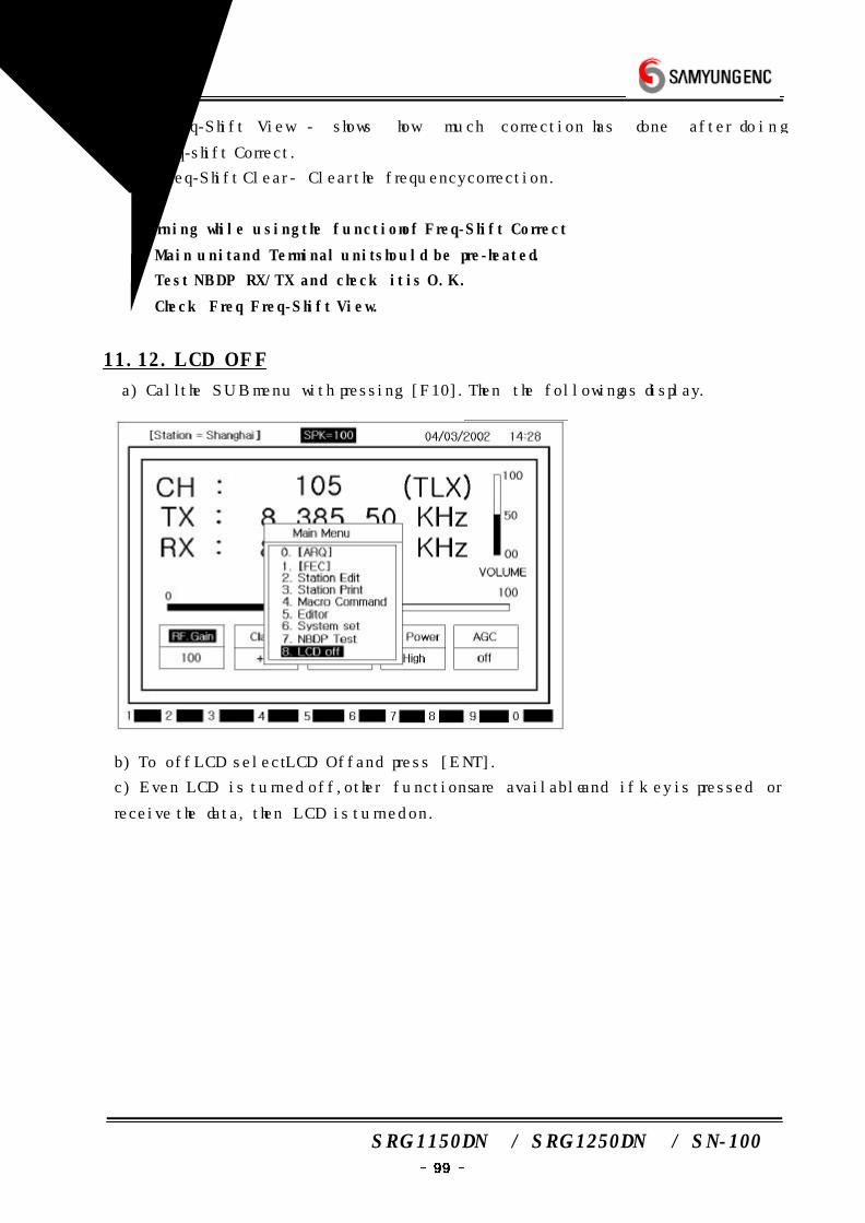
SRG-1150DN / SRG-1250DN / SN-100
(7) Freq-Shift View - shows how much correction has done after doing
Freq-shift Correct.
(8) Freq-Shift Clear - Clear the frequency correction.
※ Warning while using the function of Freq-Shift Correct
① Main unit and Terminal unit should be pre-heated.
② Test NBDP RX/TX and check it is O.K.
③ Check Freq Freq-Shift View.
11.12. LCD OFF
a) Call the SUB menu with pressing [F10]. Then the following as display.
b) To off LCD select LCD Off and press [ENT].
c) Even LCD is turned off, other functions are available and if key is pressed or
receive the data, then LCD is turned on.
SRG-1150DN / SRG-1250DN / SN-100
12. NBDP TERMINAL CIRCUIT
12.1 OVERVIEW
SN-100 consists of NBDP Receiver, MOTHER BOARD, CPU BOARD, PLL BOARD
and Power supply.
There are SRG-1150DN/SRG-1250DN connector, W/K receiving connector, printer
connector, TX ANT RF cable connector, EARTH Plate, EMG lamp connector in the
down part of rear side.
12.2 CONNECTION BOARD(T-020)
T-020 is PCB which is connecting CPU BOARD and other PCBs.
12.3 NBDP Receiving unit(T-022)
T-022 PCB is NBDP receiving unit which consists of frequency filter and amplifier,
MIXER, ATT, AGC, B.K control circuit.
12.4 PLL BOARD(T-023)
T-023 is SYNTHERSIZER PLL PCB.
12.5 POWER CIRCUIT(T-025)
Power circuit consists of constant voltage circuit.
And while power on, it makes ON main power DC 24V, convert constant voltage
+12V, +8V, +5V.
If it is over powered +32V, then power off. Prevention to reversing voltage circuit
is built-in.
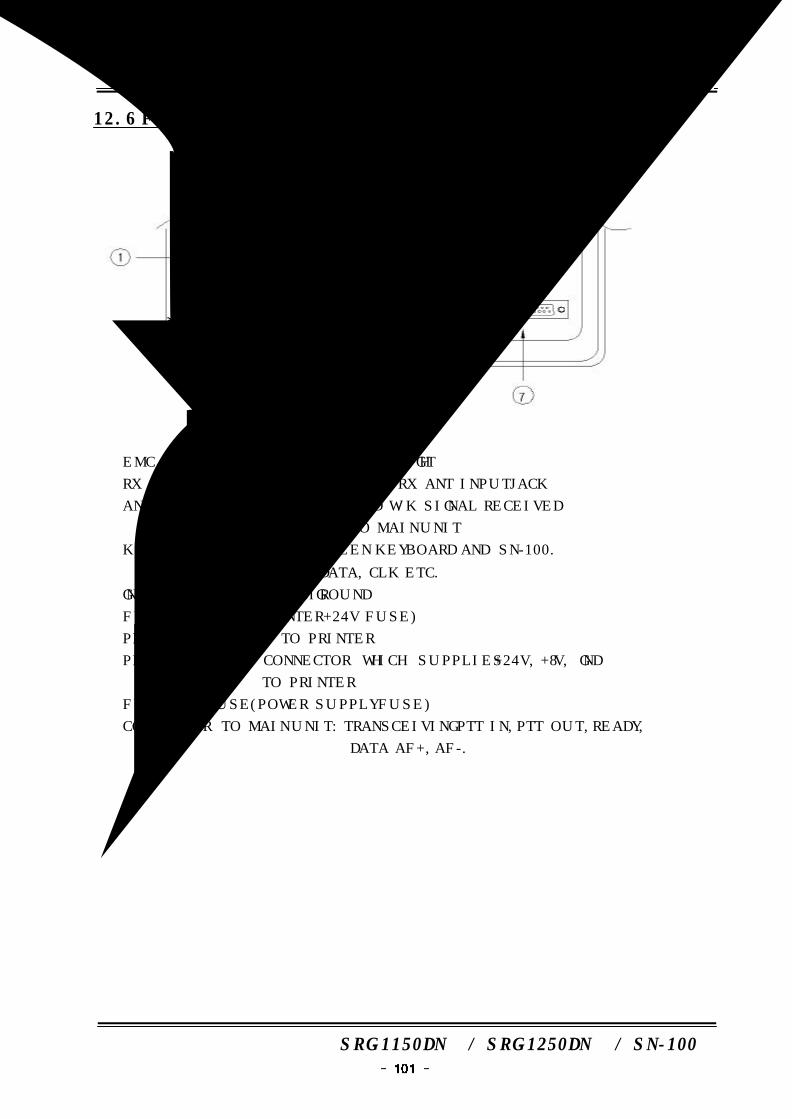
SRG-1150DN / SRG-1250DN / SN-100
12.6 FUNCTION DIAGRAM OF REAR SIDE
① EMC : SUPPLY POWER +24 TO EMG LIGHT
② RX ANT IN : IMPEDANCE 50Ω MF/HF RX ANT INPUT JACK
③ ANT OUT : CONNECT WHICH SEND W/K SIGNAL RECEIVED
FROM 'RX/ANT IN' TO MAIN UNIT
④ KEYBOARD : CONNECT BETWEEN KEYBOARD AND SN-100.
SUPPLY +5V, DATA, CLK ETC.
⑤ GND : RECEIVER SYSTEM GROUND
⑥ FUSE : 5A FUSE (PRINTER +24V FUSE)
⑦ PRINTER : CONNECT TO PRINTER
⑧ PRINTER POWER : CONNECTOR WHICH SUPPLIES +24V, +8V, GND
TO PRINTER
⑨ FUSE : 3A FUSE (POWER SUPPLY FUSE)
⑩ CONNECTOR TO MAIN UNIT : TRANSCEIVING PTT IN, PTT OUT, READY,
DATA AF+, AF-.
SRG-1150DN / SRG-1250DN / SN-100
13. TROUBLESHOOTING
13.1 OVERVIEW
Cause of TROUBLE in equipment, similar to mechanic cause and electronic cause
appeared in external and inner of equipment.
These can be block by periodic check.
This function have various protecting circuit for trouble of external or inner and blocki
ng demage of circuit and part.
However, in case of having trouble and demage, user have to find out problem.
ie, user should recognize first wether badness of equipment-self or external problem.
13.2 MEASURING INSTRUMENT
This equipment products for international radio telephone rull. maintenance &
adjustment of this equipment have to control from correcting test center by rated
testers must have testers for maintenance & adjustment daly follow as
1. multi-testor for check that don't need to be delicated ohm ,.voltage, current.
2. TEST PROBE that can be change from high-frequency signal to direct-current.
3. high-frequency transit power supply that can be check of travelling wave of until
1.6MHz ˜ 27.5MHz band max 150W˜500W
4. 100MHz band max 150W, dummy load of 50Ω
5. Frequency counter that can be check 100MHz band
6. OSCILLOSCOPE that can be check 100MHz band
7. other testers
13.3 MAINTENANCE & REPAIR
1. AIR ANTENNA
When happened interface(receiving sensitivity decrees, duplex communication
interface) during installation or using, have to check the fault of air antenna for the
first time.
a) Check that air antenna control to vertical bearings(WHIP ANTENNA) correctly.
b) Check that posit metal things around air antenna.
c) Is it O.K connect condition & insulation of air antenna and connecting parts
between transmitter receiver.
d) check the Travelling wave and reflection frequency after connect high-frequency
power supply to transmitter receiver and coaxial cable.
SRG-1150DN / SRG-1250DN / SN-100
condition of air antenna, connector, coaxial cable is not good if standing
wave(VSWR) become over 2:1 after product standing wave. if less than 2:1 after
product standing wave, it's O.K.
2. POWER SUPPLY
Check power supply circuit even though volume & squelch control, not appear any
sound and display at the front panel after connect power
transmitter receiver.
a) check be cut the fuse after open fuse holder at the rear of transmitter receiver.
(fuse : 30A)
b) Is it correct connect condition power connecting at rear of the transmitter
receiver. (Fuse be cut in case of power polarity supply opposit)
c) Check power supply voltage at the power supply connector.
If 24V±10% is (21.6~26.4V), it's correct. have to maintenance if over or less, the
badness of power supply equipment(POWER SUPPLY or BATTERY)
d) Change same goods if check power circuit T-555 PCB, it's badness.
3. TRANSMITTER
Check follow as when hand set is correct. when transmitter switch hand
set can't receiver at the operating, check the connecting condition.
a) Check Air antenna & power. can't receiver when channel selecting is incorrect or
selected unpermitted channel.
b) Check T-514(SRG-1150DN)/T-524(SRG-1250DN) and T-451(SRG-1150DN)
/T-461(SRG-1250DN) PCB, if this part is not good, have to change.
c) Not able to receive from unmatched channel and error sign is displayed.
4. RECEIVER
After check Each switch selecting is correct for the first time, check follow as ;
A. Check connect of speaker after check air antenna or power.
B. Check the PCBS T-454 and T-451(SRG-1150DN)/T-461(SRG-1250DN)
equipment, if this part is not good, have to change same goods.
C. Check to become OFF MODE, check MAIN or EXTERNAL speaker select correctly.
5. DSC Receiver
After check Each switch selecting is correct for the first time, check follow as ;
a) Check air antenna connection for DSC.
b) Check T-552 PCB or T-553 PCB of inside of equipment, if this part is not good,
have to change same goods.
SRG-1150DN / SRG-1250DN / SN-100
6. SWITCH and DISPLAY
According to manual, confirm error using or setting value and in case of no error,
check as follows.
a) check T-568 PCB of equipment
In case of error, replacing same product
b) check connector and LCD or cable connected to T-568 PCB of or T-557 of
equipment.
In case of error, replacing same product.
13.4 CAUTION
1. In case of checking transmitter unit, please contact dummy load.
2. In case of separating each PCB, pay attention to static electronic.
3. In case of modulating, use tools for modulation.
4. In case of checking or modulating, when measuring instrument contact in each
circuit, user should match signal of the circuit and PROBE of measuring instrument.
5. In case of checking or modulating, pay attention to the difference when
measuring instrument is connected into each circuit or not.
6. All maintenance had better be carried out in our agent or SAMYUNG ENC CO.,
LTD.