1. overview file:///c:/aaa csi/literature/2015 user guides
TRANSCRIPT

Babel Buster 2
Models BB2-6010-GW, SPX-GW,SP-GWModbus RTU/TCP Non-MappingGatewayRev. 1.0 – Dec. 2015
© 2015 Control Solutions, Inc.
BB2-6010-GW, SPX-GW, SP-GW User Guide Contents
1 Introduction1.1 How to Use This Guide1.2 Overview of Gateway Devices1.3 Important Safety Notice1.4 Warranty
2 Connecting Gateway for the First Time
3 Configuring Gateway3.1 Configuring Gateway with Modbus TCP as Master3.2 Configuring Gateway with Modbus RTU as Master3.3 Error Indications
Appendix A Hardware DetailsA.1 WiringA.2 Front Panel LED IndicatorsA.3 RS-485 Line Termination and BiasA.4 Babel Buster SP DB-9 Connector & DIP Switch
Babel Buster BB2-6010/SPX/SP file:///C:/AAA_CSI/Literature/2015 User Guides/BB2-6010-GW User G...
1 of 1 12/23/2015 9:28 AM
1.1 How to Use This Guide
This user guide provides background information on how the gateway works, and an overview of theconfiguration process. There are several sections for groups of tabs found in the web interface in thegateway which is accessed by opening a web browser and browsing to the IP address of the device.
You should at least read the overview sections to gain an understanding of how the gateway functions.You can use the remaining sections as reference material to look up as needed. There is a "Quick Help"section at the bottom of each web page in the gateway which is generally sufficient for quick reference insetting up the gateway.
Throughout this user guide, screen shots taken from a Babel Buster BB2-6010-GW are used to illustrate.However, the same instructions apply to Babel Buster SPX-GW and Babel Buster SP-GW with eachavailable screen looking nearly identical.
1.2 Overview of Gateway Devices
The Babel Buster BB2-6010-GW, Babel Buster SPX-GW, and Babel Buster SP-GW are non-mappingModbus gateways used to simply forward Modbus RTU requests and responses to Modbus TCP, and viceversa. Most Control Solutions gateways involve mapping, and the gateway itself contains registers orobjects which hold copies of data found in other devices. This intermediate data buffering is what allowsaccess to the same data from multiple protocols. The non-mapping gateway discussed here does notcontain any of its own registers. It simply forwards whatever request it receives to the other side andsimply repackages and retransmites exactly the same request (regardless of whether it was a correctrequest).
The process of "repackaging" the Modbus request or response is illustrated below. The core of a Modbusdata packet is the same for RTU and TCP. It contains a slave address (or unit number), a function code,and some data. The "data" is most often a starting register number, register count, and register data (ifwriting).
If the data packet is being sent via Modbus RTU, the first character transmitted is the slave address, andthe last two characters are a CRC type checksum. If the data packet is being sent via Modbus TCP, there isa TCP header at the beginning of the packet, and the last byte of that packet is the same slave address orunit number that would have been sent via RTU. The RTU checksum is not included because Ethernet has
1. Overview file:///C:/AAA_CSI/Literature/2015 User Guides/BB2-6010-GW User G...
1 of 2 12/23/2015 9:28 AM
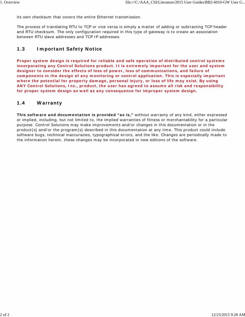
its own checksum that covers the entire Ethernet transmission.
The process of translating RTU to TCP or vice versa is simply a matter of adding or subtracting TCP headerand RTU checksum. The only configuration required in this type of gateway is to create an associationbetween RTU slave addresses and TCP IP addresses.
1.3 Important Safety Notice
Proper system design is required for reliable and safe operation of distributed control systemsincorporating any Control Solutions product. It is extremely important for the user and systemdesigner to consider the effects of loss of power, loss of communications, and failure ofcomponents in the design of any monitoring or control application. This is especially importantwhere the potential for property damage, personal injury, or loss of life may exist. By usingANY Control Solutions, Inc., product, the user has agreed to assume all risk and responsibilityfor proper system design as well as any consequence for improper system design.
1.4 Warranty
This software and documentation is provided “as is,” without warranty of any kind, either expressedor implied, including, but not limited to, the implied warranties of fitness or merchantability for a particularpurpose. Control Solutions may make improvements and/or changes in this documentation or in theproduct(s) and/or the program(s) described in this documentation at any time. This product could includesoftware bugs, technical inaccuracies, typographical errors, and the like. Changes are periodically made tothe information herein; these changes may be incorporated in new editions of the software.
1. Overview file:///C:/AAA_CSI/Literature/2015 User Guides/BB2-6010-GW User G...
2 of 2 12/23/2015 9:28 AM

Follow these steps to make the initial connection to the BB2-6010-GW.
(a) Connect power.
Babel Buster BB2-6010-GW: Apply +12 to +24VDC or 24VAC to the terminal marked “POWER”, andcommon or ground the the terminal marked “GND”.
Babel Buster SPX-GW: Apply +12 to +24VDC or 24VAC to the terminal marked “POWER”, and common orground the the terminal marked “GND”.
Babel Buster SP-GW: Plug power adapter into power connector marked "Power".
2. Connecting the Gateway for the First Time file:///C:/AAA_CSI/Literature/2015 User Guides/BB2-6010-GW User G...
1 of 4 12/23/2015 9:29 AM

(b) Connect a CAT5 cable between the RJ-45 jack on the gateway, and your network switch or hub. Youcannot connect directly to your PC unless you use a “crossover” cable.
(c) Apply power.
BB2-6010-GW: A blue LED inside the case should light indicating power is present. SPX-GW: A green LEDinside the case close to the RJ45 connector should light indicating power is present. SP-GW: The LED nextto the power connector should light red for a time (but will go out after bootup since this singleLED doubles as communication indicator).
All models: If the link LED on the RJ45 jack is not on, check your Ethernet cable connections. Both link andactivity LEDs on the RJ45 jack will be on solid for a short time during boot-up. The entire bootup processwill take 1-2 minutes, during which time you will not be able to connect with a browser.
Ethernet link LED is the yellow LED integrated into the CAT5 connector on BB2-6010 and SPX, and greenon SP. Ethernet activity LED is the green LED integrated into the CAT5 connector on BB2-6010 and SPX,and yellow on SP (SP is reverse of other two).
(d) The default IP address as shipped is 10.0.0.101. If your PC is not already on the 10.0.0.0 domain, youwill need to add a route on your PC (XP only). Do this by opening a command prompt. First type “ipconfig”and note the IP address listed. This is your PC’s IP address. Now type the command
route add 10.0.0.0 mask 255.255.255.0 1.2.3.4
but substitute your PC’s IP address for 1.2.3.4.
This generally works, but if this fails, you will need to temporarily change your computer’s IP address to afixed address that starts with 10.0.0. and ends with anything but 101.
2. Connecting the Gateway for the First Time file:///C:/AAA_CSI/Literature/2015 User Guides/BB2-6010-GW User G...
2 of 4 12/23/2015 9:29 AM

(e) Open your browser, and enter “http://10.0.0.101/” in the address window. You should see a page withthe “Babel Buster BB2-6010” header shown above (or as applicable by model). From this point, you willfind help on each page in the web site contained within the product.
(f) When you click on any of the page tabs such as System Setup, you will be asked for a user name andpassword. The default login is user name “system” with password “admin”. You can also log in as “root”using password “buster”. You must log in as “root” if you will be changing the IP address.
(g) To can change the IP address of the gateway, go to the Network page under System :: Setup. Thefollowing page should appear. Change the IP address, and subnet mask and gateway if applicable. ClickChange IP to save the changes. The process of programming this into Flash takes around half a minute.The new IP address only takes effect following the next system restart or power cycle.
2. Connecting the Gateway for the First Time file:///C:/AAA_CSI/Literature/2015 User Guides/BB2-6010-GW User G...
3 of 4 12/23/2015 9:29 AM

(h) Most changes are stored in an XML configuration file in the device’s Flash file system. Only a few arestored differently, and the IP address is one of those. Normally, clicking Update on any configuration pageonly stores that configuration information to a temporary RAM copy of the configuration file. To make yourchanges other than IP address permanent, you must click Save on the Config File page (System :: Setup:: Config File).
2. Connecting the Gateway for the First Time file:///C:/AAA_CSI/Literature/2015 User Guides/BB2-6010-GW User G...
4 of 4 12/23/2015 9:29 AM

The gateway is configured based on which side is Modbus master. If your Modbus TCP master wants to getdata from Modbus RTU slaves, then configure the gateway with Modbus TCP as master. If your ModbusRTU master wants to get data from Modbus TCP slaves, then configure the gateway with Modbus RTU asmaster.
Regardless of which side is master, one setting that is always required is setting the IP address of thegateway itself. This was already mentioned in the previous section, but for purposes of reiterating thesteps required to configure the gateway, set the IP address from the Network page as shown here.
3.1 Configuring Gateway with Modbus TCP as Master
If Modbus TCP is master, then from the perspective of your slave RTU devices, the RTU port on thisgateway must also be master. Select master simply by clicking the "Iam the RTU Master" button.
3. Configuring Gateway as a Modbus RTU Master file:///C:/AAA_CSI/Literature/2015 User Guides/BB2-6010-GW User G...
1 of 6 12/23/2015 9:29 AM

Select baud rate and parity from the drop down list. Click either Master or Slave buttons to select type ofoperation. Enter timing parameters or address as applicable. Click update to register your changes.
IMPORTANT: Set timeout to something long enough for the device(s). If too short, the gateway will notwait long enough for a response from the Modbus slave device, and the result will be a lot of "noresponse" errors from the device even though the device is perfectly functional.
Once you have made all of the appropriate settings on this page, you must go to the Config File page andclick Save to retain these settings past the next power cycle. Refer to the previous section to see where tofind the Config File page.
Configuring the non-mapping gateway with Modbus TCP as master is very simple. You set up the ports andthat is all. You do not need to do anything on the TCP Device Map page - that is for configuring in theopposite direction.
3.2 Configuring Gateway with Modbus RTU as Master
If your Modbus RTU master wants to view one or more Modbus TCP devices as slaves, then from theperspective of your RTU master, this gateway must be configured as an RTU slave. Make that selection byclicking "I am one or more RTU Slaves". You must also select the baud rate that your Modbus RTU masteris using, as well as parity and whether 2 stop bits are required.
3. Configuring Gateway as a Modbus RTU Master file:///C:/AAA_CSI/Literature/2015 User Guides/BB2-6010-GW User G...
2 of 6 12/23/2015 9:29 AM

When Modbus RTU is master, you need to tell this gateway what IP address is mapped to which RTU slaveaddress. If there is a one to one correlation between RTU slave address and Modbus TCP address, enterthem as illustrated below. Here we see RTU slave addresses 1 through 3 corresponding to three differentIP addresses.
The first and last slave address incoming in this example simple mean that RTU slave addresses "1through 1" correspond to the first IP address on the list, and unit number 1 will be transmitted as unit orslave ID in the TCP packet. The RTU slave addresses "2 through 2" mean RTU slave address 2 willtranslate to the second IP address, but its unit number will be sent as 1. If all of the Modbus TCP devicesexpect to see unit number (or slave address) of 1, this mapping is how we instruct the gateway totranslate the slave address. Often a Modbus TCP device will disregard the unit number and it doesn't carewhat number you send.
3. Configuring Gateway as a Modbus RTU Master file:///C:/AAA_CSI/Literature/2015 User Guides/BB2-6010-GW User G...
3 of 6 12/23/2015 9:29 AM

There are instances where a Modbus TCP device contains several unit numbers at the same IP address.This is common in a multi-channel device where unit specifies channel number. Since RTU does not havethe luxury of this sort of multi-layer addressing, your RTU master will need a way of seeing each channelas a separate RTU slave address. The non-mapping gateway can do this for you. We say"non-mapping" because there is no register or object mapping common to other gateways. But RTU slaveaddresses are being mapped, so in that sense, the non-mapping gateway is still doing some form ofmapping.
The example below shows RTU slave addresses 1 through 5 being sent to the first IP address in the list,and unit numbers on the TCP side will be sent as 1 through 5, corresponding to RTU slave addresses 1through 5. The second line shows RTU slave addresses 6 through 10 being sent to the second IP addresson the list, and unit numbers on the TCP side will be sent as 1 through 5 corresponding to RTU slaveaddresses 6 through 10.
3. Configuring Gateway as a Modbus RTU Master file:///C:/AAA_CSI/Literature/2015 User Guides/BB2-6010-GW User G...
4 of 6 12/23/2015 9:29 AM

IMPORTANT: Once you have set up the serial port and made all of your address entries on the TCP DeviceMap, you must go to the Config File page and click Save to retain your settings through the next powercycle.
3.3 Error Indications
Errors on the TCP side with RTU as master will be indicated by Connection Status. The most common errorwill be status code 5, which simply means unable to connect. A Connection Status of zero means no errorsdetected. However, if the gateway has not received any requests from RTU, then it will not haveattempted to connect to TCP yet. Therefore, status is only meaningful if the RTU master is sendingrequests to the gateway.
Errors on the RTU side with TCP as master will be indicated on the Diganostics page illustrated here. Atabulation of errors detected by the gateway will be noted here.
3. Configuring Gateway as a Modbus RTU Master file:///C:/AAA_CSI/Literature/2015 User Guides/BB2-6010-GW User G...
5 of 6 12/23/2015 9:29 AM

3. Configuring Gateway as a Modbus RTU Master file:///C:/AAA_CSI/Literature/2015 User Guides/BB2-6010-GW User G...
6 of 6 12/23/2015 9:29 AM

Appendix A Hardware Details
A.1 Wiring
Wiring for the Babel Buster BB2-6010 is illustrated below.
Wiring for the Babel Buster SPX is illustrated below (see section A.4 for SP).
A. Hardware Details file:///C:/AAA_CSI/Literature/2021 User Guides/Errata Updates/BB2-6...
1 of 6 4/8/2021, 8:54 AM

Wire the gateway as illustrated. Follow all conventional standards for wiring of EIA-485 networks when
connecting the Modbus RTU EIA-485 (RS485) network. This includes use and termination of shield,
termination of the network, and grounding.
IMPORTANT: Although EIA-485 (RS485) is thought of as a 2-wire network, you MUST include a third
conductor connected to GND or common at each device so that all devices are operating at close to the
same ground potential. Proper grounding of equipment should ensure proper operation without the third
conductor; however, proper grounding often cannot be relied upon. If large common mode voltages are
present, you may even need to insert optically isolated repeaters between EIA-485 devices.
Use standard CAT5 cables for Ethernet connections. Use control wire as applicable for local electrical codes
for connecting the 24V (AC or DC) power supply.
Note that in addition to connecting power supply common to a GND terminal, you must also connect a
GND terminal to earth ground in order to ensure proper ESD protection.
A.2 Front Panel LED Indicators
Power-up LED behavior for BB2-6010: Following a server boot-up delay, all LEDs on front panel will turn on
yellow or red for half a second, then all will turn on green for half a second. Then they will proceed to
indicate as normally defined for the indicators.
Power-up LED behavior for SPX: Following a server boot-up delay, all LEDs will turn on briefly, then
proceed to indicate as normally defined for the indicators.
Power-up LED behavior for SP: The single power/status LED will light up red and remain on until server
boot-up.
A. Hardware Details file:///C:/AAA_CSI/Literature/2021 User Guides/Errata Updates/BB2-6...
2 of 6 4/8/2021, 8:54 AM

Babel Buster BB2-6010 and SPX request/reply LEDs reflect RTU traffic while the Ethernet activity LED
will indicate TCP traffic. To see TCP errors, one needs to look at the Errors page in the web UI.
Babel Buster SP: Since there is only one LED available, it simply indicates Modbus traffic. To see either
TCP or RTU errors, one needs to look at the Errors pages in the web UI.
Babel Buster BB2-6010 LEDs indicate as follows (LEDs are bi-color):
DEV DATAFlashes yellow each time a request is sent when operating as Modbus
Master, or each time a request is received when operating as Modbus Slave.
DEV STATUS
Operating as Modbus Master, flashes green each time a good response is
received, or red when an error code is received, the request times out, or
there is a flaw in the response such as CRC error.
Operating as Modbus Slave, flashes green each time a good response is
sent, or red if an exception code is sent (meaning the received request
resulted in an error).
Babel Buster SPX LEDs indicate as follows:
YellowFlashes each time a request is sent when operating as Modbus Master, or
each time a request is received when operating as Modbus Slave.
Green
Operating as Modbus Master, flashes each time a good response is received.
Operating as Modbus Slave, flashes green each time a good response is
sent.
Red
Operating as Modbus Master, flashes when an error code is received, the
request times out, or there is a flaw in the response such as CRC error.
A. Hardware Details file:///C:/AAA_CSI/Literature/2021 User Guides/Errata Updates/BB2-6...
3 of 6 4/8/2021, 8:54 AM

Operating as Modbus Slave, flashes if an exception code is sent (meaning
the received request resulted in an error).
Ethernet link LED is the yellow LED integrated into the CAT5 connector on BB2-6010 and SPX, and green
on SP. Ethernet activity LED is the green LED integrated into the CAT5 connector on BB2-6010 and SPX,
and yellow on SP (SP is reverse of other two).
A.3 RS-485 Line Termination & Bias
Enable line termination only when this device is placed at the end of the network. Termination should only
be enabled at two points on the network, and these two points must be specifically the end points.
Enable line bias when needed. Line bias should only be enabled at one point on the network, and does not
have to be the end point. Line bias holds the line in a known neutral state when no devices are
transmitting. Without bias, the transition from offline to online by a transmitter can look like a false start
bit and cause loss of communication.
The line conditioning options are enabled when the respective shunt is moved to the position indicated by
the white block next to the 3-pin header. Putting the shunt on the opposite 2 pins disables the option, and
is simply a place to store the shunt.
Jumper locations for Babel Buster BB2-6010:
Jumper locations for Babel Buster SPX (see following section for SP):
A. Hardware Details file:///C:/AAA_CSI/Literature/2021 User Guides/Errata Updates/BB2-6...
4 of 6 4/8/2021, 8:54 AM

The "Init" jumper on the server module should only be used when advised by tech support. Installing this
jumper prior to power-up causes the server to go into firmware update mode.
A.4 Babel Buster SP DB-9 Connector & DIP Switch
Pin connections are shown below. RS-485 (EIA-485) is by definition 2-wire. Any reference to 4-wire
RS-485 is really EIA-422. Babel Buster SP supports EIA-422, but also automatically supports EIA-485 with
a simple wiring configuration. Simply connect all the pluses together, and all the minuses together.
Connect RXD+ to TXD+ on Babel Buster SP, and that one connection to + on your Modbus device. Do the
same with the minus side. Then set the DIP switches for EIA-485 half duplex, termination ON. Although
called "2-wire" you really need 3 conductors, 2 wires for signal + and - with a third conductor for
ground/common.
If your Modbus device has its RS-485 terminal marked A and B, be aware that about half of the equipment
out there has A and B backwards. This is due to the fact that A and B as published by EIA-485 are the
reverse of A and B as defined by the RS-485 chip makers. Somewhere along the line they didn't compare
notes. There is no harm done in reversing the wires, it simply will not communicate. If you are having
trouble communicating, especially if the device terminals are marked A and B, try reversing them.
The above view is the male DB9 as seen looking into the Babel Buster SP. Important: This is NOT a
PC COM port. Study the wiring table below carefully. Also keep in mind that while Pin 1 is on the left on the
male connector, Pin 1 will be on the right looking at the female connector.
A. Hardware Details file:///C:/AAA_CSI/Literature/2021 User Guides/Errata Updates/BB2-6...
5 of 6 4/8/2021, 8:54 AM

In addition to connecting wiring as indicated above, you need to change the DIP switch settings to select
what type of port you are configuring.
A. Hardware Details file:///C:/AAA_CSI/Literature/2021 User Guides/Errata Updates/BB2-6...
6 of 6 4/8/2021, 8:54 AM