1 lecture 30 read only memory (rom). 2 overview °read-only memory can normally only be read...
TRANSCRIPT

1
Lecture 30Read Only Memory (ROM)

2
Overview
° Read-only memory can normally only be read
° Internal organization similar to SRAM
° ROMs are effective at implementing truth tables• Any logic function can be implemented using ROMs
° Multiple single-bit functions embedded in a single ROM
° Also used in computer systems for initialization• ROM doesn’t lose storage value when power is removed
° Very useful for implementing FSMs

3
Read-Only Memory (ROM)
° An array of semiconductor devices• diodes
• transistors
• field effect transistors
° 2N words by M bits
° Data can be read but not changed• (normal operating conditions)
Data is written to the ROM once, and read from the ROM many times.
A read-only memory (ROM) consists of an array of semiconductor devices that are interconnected to store a set of binary data.
Once binary data is stored in the ROM, it can be read out whenever desired, but the data that is stored cannot be changed under normal operating conditions.

4
ROM° ROMs are actually combinational devices, not sequential
ones!• You can’t store arbitrary data into a ROM, so the same address will always
contain the same data.
• You can think of a ROM as a combinational circuit that takes an address as input, and produces some data as the output.
° A ROM table is basically just a truth table.• The table shows what data is stored at each ROM address.
• You can generate that data combinationally, using the address as the input.AddressA2A1A0
DataV2V1V0
000 000001 100010 110011 100
100 101101 000110 011111 011

5
° N input bits
° 2N words by M bits
° Implement M arbitrary functions of N variables• Example 8 words by 5 bits:
Read-Only Memory (ROM)
3 InputLines
ABC
F0 F1 F2 F3 F4
5 Output Lines
ROM8 wordsx 5 bits

6
6
ROM – Basic Structure
address
data

7
° ROM = "Read Only Memory"• values of memory locations are fixed ahead of time
° A ROM can be used to implement a truth table• if the address is m-bits, we can address 2m entries in the ROM.• our outputs are the bits of data that the address points to.
• m is the "height", and n is the "width"
ROM Implementation
m n
0 0 0 0 0 1 10 0 1 1 1 0 00 1 0 1 1 0 00 1 1 1 0 0 0 1 0 0 0 0 0 0 1 0 1 0 0 0 11 1 0 0 1 1 01 1 1 0 1 1 1

8
° Suppose there are 10 inputs10 address lines (i.e., 210 = 1024 different
addresses)
° Suppose there are 20 outputs
° ROM is 210 x 20 = 20K bits (and a rather unusual size)
° Rather wasteful, since lots of storage bits• For functions, doesn’t take advantage of K-maps, other
minimization
ROM Implementation

9
Each minterm of each function can be specified
Read-Only Memory (ROM)
3 InputsLines
ABC
F0 F1 F2 F3 F4
5 Outputs Lines
ROM8 wordsx 5 bits
A B C F0 F1 F 2 F 3 F 4
0 0 0 0 1 0 1 00 0 1 1 1 1 1 00 1 0 0 0 0 1 10 1 1 1 1 1 0 11 0 0 0 1 0 1 01 0 1 0 1 1 1 11 1 0 1 0 1 0 11 1 1 1 1 0 1 0

10
ROM Internal Structure
...
n InputsLines
n bitdecoder
...
m Outputs Lines
.
.
.Memory Array
2n words x m bits

11
ROM Memory Array
3 to 8decoder
A
B
C
m0=A’B ’C ’
m1=A’B ’C
m2=A’BC’
m3=A’BC
m4=AB’C ’
m5=AB’C
m6=ABC’
m7=ABC
F0 F1 F2 F3 F4

12
Inside the ROM
° Alternate view• Each possible horizontal/vertical intersection indicates
a possible connection
° Or gates at bottom output the word selected by the decoder (32 x 8)

13
ROM Example
A B C F G H
0 0 00 0 10 1 00 1 11 0 01 0 11 1 01 1 1
Specify a truth table for a ROM which implements:
F = AB + A’BC’
G = A’B’C + C’
H = AB’C ’ + ABC’ + A’B’C

14
ROM Example
A B C F G H
0 0 0 00 0 1 00 1 0 10 1 1 01 0 0 01 0 1 01 1 0 11 1 1 1
Specify a truth table for a ROM which implements:
F = AB + A’BC’
G = A’B’C + C’
H = AB’C ’ + ABC’ + A’B’C

15
ROM Example
Specify a truth table for a ROM which implements:
F = AB + A’BC’
G = A’B’C + C’
H = AB’C ’ + ABC’ + A’B’CA B C F G H
0 0 0 0 1 00 0 1 0 1 10 1 0 1 1 00 1 1 0 0 01 0 0 0 1 11 0 1 0 0 01 1 0 1 1 11 1 1 1 0 0
16
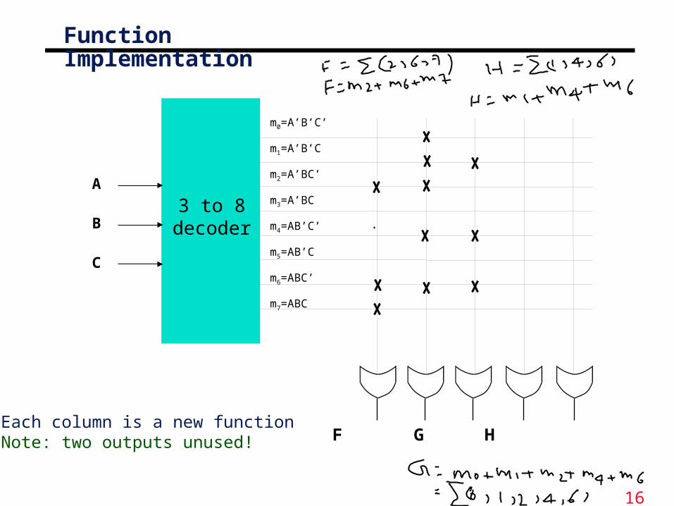
Function Implementation
3 to 8decoder
A
B
C
m0=A’B ’C ’
m1=A’B ’C
m2=A’BC’
m3=A’BC
m4=AB’C ’
m5=AB’C
m6=ABC’
m7=ABC
F G H Each column is a new functionNote: two outputs unused!

17

18
Decoders
X Y Z C S
0 0 0 0 00 0 1 0 10 1 0 0 10 1 1 1 01 0 0 0 11 0 1 1 01 1 0 1 01 1 1 1 1
° We can already convert truth tables to circuits easily, with decoders.
° For example, you can think of this old circuit as a memory that “stores” the sum and carry outputs from the truth table on the right.

19
ROM setup
° ROMs are based on this decoder implementation of functions.
• A blank ROM just provides a decoder and several OR gates.
• The connections between the decoder and the OR gates are “programmable,” so different functions can be implemented.
° To program a ROM, you just make the desired connections between the decoder outputs and the OR gate inputs.

20
ROM example
V2 = m(1,2,3,4) V1 = m(2,6,7) V0 = m(4,6,7)
A2
A1
A0
° Here are three functions, V2V1V0, implemented with an 8 x 3 ROM.
° Blue crosses (X) indicate connections between decoder outputs and OR gates. Otherwise there is no connection.

21
Same Example° Here is an alternative presentation of the same 8 x 3 ROM,
using “abbreviated” OR gates to make the diagram neater.
° This combinational circuit can be considered a read-only memory.
• It stores eight words of data, each consisting of three bits.
• The decoder inputs form an address, which refers to one of the eight available words.
• So every input combination corresponds to an address, which is “read” to produce a 3-bit data output.
V2 = m(1,2,3,4)V1 = m(2,6,7)V0 = m(4,6,7)
V2 V1 V0
A2
A1
A0
AddressA2A1A0
DataV2V1V0
000 000001 100010 110011 100
100 101101 000110 011111 011

22
ROMs vs. RAMs
° There are some important differences between ROM and RAM.
• ROMs are “non-volatile”—data is preserved even without power. On the other hand, RAM contents disappear once power is lost.
• ROMs require special (and slower) techniques for writing, so they’re considered to be “read-only” devices.
° Some newer types of ROMs do allow for easier writing, although the speeds still don’t compare with regular RAMs.
• MP3 players, digital cameras and other toys use CompactFlash, Secure Digital, or MemoryStick cards for non-volatile storage.
• Many devices allow you to upgrade programs stored in “flash ROM.”

23
ROM Implementation of a Moore Machine
° ROMs implement combinational logic
° Note that ROMs do not hold state
° How would you determine the maximum clock frequency of this circuit?
• Look at the FF to FF path (NS to PS)
ROM ROM
Present State
Next State
OutputsInputs

24
ROM Implementation of a Mealy Machine
° ROMs implement combinational logic
° Note that ROMs do not hold state
° How would you determine the maximum clock frequency of this circuit?
• Look at the FF to FF path (NS to PS)
ROM
ROMPresent State
Next State
OutputsInputs

25
Summary° ROMs provide stable storage for data
° ROMs have address inputs and data outputs• ROMs directly implement truth tables
° ROMs can be used effectively in Mealy and Moore machines to implement combinational logic
° In normal use ROMs are read-only• They are only read, not written
° ROMs are often used by computers to store critical information
• Unlike SRAM, they maintain their storage after the power is turned off