1 lasers: fundamentals, types, and operations - wiley · pdf file1 1 lasers: fundamentals,...
TRANSCRIPT
1
1Lasers: Fundamentals, Types, and OperationsSubhash Chandra Singh, Haibo Zeng, Chunlei Guo, and Weiping Cai
The acronym LASER, constructed from Light Amplification by Stimulated Emissionof Radiation, has become so common and popular in every day life that it is nowreferred to as laser. Fundamental theories of lasers, their historical developmentfrom milliwatts to petawatts in terms of power, operation principles, beam char-acteristics, and applications of laser have been the subject of several books [1–5].Introduction of lasers, types of laser systems and their operating principles, meth-ods of generating extreme ultraviolet/vacuum ultraviolet (EUV/VUV) laser lights,properties of laser radiation, and modification in basic structure of lasers are themain sections of this chapter.
1.1Introduction of Lasers
1.1.1Historical Development
The first theoretical foundation of LASER and MASER was given by Einsteinin 1917 using Plank’s law of radiation that was based on probability coefficients(Einstein coefficients) for absorption and spontaneous and stimulated emissionof electromagnetic radiation. Theodore Maiman was the first to demonstrate theearliest practical laser in 1960 after the reports by several scientists, including thefirst theoretical description of R.W. Ladenburg on stimulated emission and negativeabsorption in 1928 and its experimental demonstration by W.C. Lamb and R.C.Rutherford in 1947 and the proposal of Alfred Kastler on optical pumping in 1950and its demonstration by Brossel, Kastler, and Winter two years later. Maiman’s firstlaser was based on optical pumping of synthetic ruby crystal using a flash lampthat generated pulsed red laser radiation at 694 nm. Iranian scientists Javan andBennett made the first gas laser using a mixture of He and Ne gases in the ratio of1 : 10 in the 1960. R. N. Hall demonstrated the first diode laser made of galliumarsenide (GaAs) in 1962, which emitted radiation at 850 nm, and later in the sameyear Nick Holonyak developed the first semiconductor visible-light-emitting laser.
Nanomaterials: Processing and Characterization with Lasers, First Edition.Edited by Subhash Chandra Singh, Haibo Zeng, Chunlei Guo, and Weiping Cai.© 2012 Wiley-VCH Verlag GmbH & Co. KGaA. Published 2012 by Wiley-VCH Verlag GmbH & Co. KGaA.
2 1 Lasers: Fundamentals, Types, and Operations
1.1.2Basic Construction and Principle of Lasing
Basically, every laser system essentially has an active/gain medium, placed betweena pair of optically parallel and highly reflecting mirrors with one of them partiallytransmitting, and an energy source to pump active medium. The gain media may besolid, liquid, or gas and have the property to amplify the amplitude of the light wavepassing through it by stimulated emission, while pumping may be electrical oroptical. The gain medium used to place between pair of mirrors in such a way thatlight oscillating between mirrors passes every time through the gain medium andafter attaining considerable amplification emits through the transmitting mirror.
Let us consider an active medium of atoms having only two energy levels: excitedlevel E2 and ground level E1. If atoms in the ground state, E1, are excited to theupper state, E2, by means of any pumping mechanism (optical, electrical discharge,passing current, or electron bombardment), then just after few nanoseconds oftheir excitation, atoms return to the ground state emitting photons of energyhν = E2 − E1. According to Einstein’s 1917 theory, emission process may occur intwo different ways, either it may induced by photon or it may occur spontaneously.The former case is termed as stimulated emission, while the latter is knownas spontaneous emission. Photons emitted by stimulated emission have the samefrequency, phase, and state of polarization as the stimulating photon; therefore theyadd to the wave of stimulating photon on a constructive basis, thereby increasingits amplitude to make lasing. At thermal equilibrium, the probability of stimulatedemission is much lower than that of spontaneous emission (1 : 1033), thereforemost of the conventional light sources are incoherent, and only lasing is possiblein the conditions other than the thermal equilibrium.
1.1.3Einstein Relations and Gain Coefficient
Consider an assembly of N1 and N2 atoms per unit volume with energies E1
and E2(E2 > E1) is irradiated with photons of density ρν = N hυ, where [N] is thenumber of photons of frequency ν per unit volume. Then the stimulated absorptionand stimulated emission rates may be written as N1ρvB12 and N2ρvB21 respectively,where B12 and B21 are constants for up and downward transitions, respectively,between a given pair of energy levels. Rate of spontaneous transition depends onthe average lifetime, τ21, of atoms in the excited state and is given by N2A21, whereA21 is a constant. Constants B12, B21, and A21 are known as Einstein coefficients.Employing the condition of thermal equilibrium in the ensemble, Boltzmannstatistics of atomic distribution, and Planck’s law of blackbody radiation, it is easyto find out B12 = B21, A21 = B21(8πhν3/c3), known as Einstein relations, and ratio,R = exp(hν/kT) − 1, of spontaneous and stimulated emissions rates. For example,if we have to generate light of 632.8 nm (ν = 4.74 × 10¹⁴ Hz) wavelength at roomtemperature from the system of He–Ne, the ratio of spontaneous and stimulatedemission will be almost 5 × 1026, which shows that for getting strong lasing one

1.1 Introduction of Lasers 3
has to think apart from the thermal equilibrium. For shorter wavelength, laser,ratio of spontaneous to stimulated emission is larger, ensuring that it is moredifficult to produce UV light using the principle of stimulated emission comparedto the IR. Producing intense laser beam or amplification of light through stimulatedemission requires higher rate of stimulated emission than spontaneous emissionand self-absorption, which is only possible for N2 > N1 (as B12 = B21) even thoughE2 > E1 (opposite to the Boltzmann statistics). It means that one will have to createthe condition of population inversion by going beyond the thermal equilibrium toincrease the process of stimulated emission for getting intense laser light.
If a collimated beam of monochromatic light having initial intensity I0 passesthrough the mentioned active medium, after traveling length x, intensity ofthe beam is given by I(x) = I0e−αx, where α is the absorption coefficient of themedium, which is proportional to the difference of N1 and N2. In the case ofthermal equilibrium N1 � N2 the irradiance of the beam will decrease with thelength of propagation through the medium. However, in the case of populationinversion, (N2 > N1) − α, will be positive and the irradiance of the beam willincrease exponentially as I(x) = I0ekx, where k is the gain coefficient of themedium and may be given by k = (nNdhν21B21)/c, where Nd is N2−N1, c is speedof light, and n is refractive index of the medium.
1.1.4Multilevel Systems for Attaining Condition of Population Inversion
Considering the case of two energy level system under optical pumping, wehave already discussed that B12 = B21, which means that even with very strongpumping, population distribution in upper and lower levels can only be made equal.Therefore, optical as well as any other pumping method needs either three or fourlevel systems to attain population inversion. A three level system (Figure 1.1a)irradiated by intense light of frequency ν02 causes pumping of large number ofatoms from lowest energy level E0 to the upper energy level E2. Nonradiative decayof atoms from E2 to E1 establishes population inversion between E1 and E0 (i.e.,N1 > N0), which is practically possible if and only if atoms stay for longer time inthe state E1 (metastable state, i.e., have a long lifetime) and the transition from E2 toE1 is rapid. If these conditions are satisfied, population inversion will be achievedbetween E0 and E1, which makes amplification of photons of energy E1 − E0 bystimulated emission. Larger width of the E2 energy level could make possibleabsorption of a wider range of wavelengths to make pumping more effective, whichcauses increase in the rate of stimulated emission. The three level system needsvery high pumping power because lower level involved in the lasing is the groundstate of atom; therefore more than half of the total number of atoms have to bepumped to the state E1 before achieving population inversion and in each of thecycle, energy used to do this is wasted. The pumping power can be greatly reducedif the lower level involved in the lasing is not ground state, which requires at least afour level system (Figure 1.1b). Pumping transfers atoms from ground state to E3,from where they decay rapidly into the metastable state E2 to make N2 larger than

4 1 Lasers: Fundamentals, Types, and Operations
NN
E0
EE1
E3
E0
E
E1
E2Fast decay
Fas
t dec
ay
Fast decay
Pum
ping
Pum
ping
Lasin
g
Lasing
(a) (b)
Figure 1.1 Energy level diagram for (a) three- and (b) four level laser systems.
N1 to achieve the condition of population inversion between E2 and E1 at moderatepumping.
1.1.5Threshold Gain Coefficient for Lasing
Laser beam undergoes multiple oscillations (through active medium) between pairof mirrors to achieve considerable gain before it leaves the cavity through partiallyreflecting mirror. Laser oscillation can only sustain in the active medium if it attainsat least unit gain after a round-trip between mirrors and maintains it overcomingvarious losses inside the cavity. If we incorporate these losses, the effective gaincoefficient reduces to k − ϒ , where ϒ is the loss coefficient of the medium. Ifround-trip gain G were less than unity, the laser oscillation would die out, whileit would grow if the G value were larger than unity. Let us consider that the laserbeam of intensity I0 passes through the active medium, homogeneously filled in thelength L between the space of two mirrors M1 and M2 with reflectivities R1 and R2,respectively. The beam of intensity I0 initiates from the surface of M1 and attainsintensity I1(I1 = I0exp(k − ϒ)L) after traveling a length L to reach at the surface ofM2. After reflection from M2 and traveling back to M1, the light intensity becomes I2
(I′1 = I1R2 due to reflection and I2 = I′
1exp(k − ϒ)L), which finally becomes I′2 after
reflection from M1 to complete a round-trip (I′2 = I2R1 = I0R1R2exp2(k − ϒ)L).
Waves starting from the surface of mirror M1 and those that have completed oneor more round trips are in the same phase. Now, the gain G(I′
2/I0) attained in around-trip should be at least unity to sustain the laser oscillation inside the cavity,therefore R1R2 exp2(k − ϒ)L = 1 is the threshold condition, which gives a value ofϒ + (2L)−1 ln(R1R2)−1 for threshold gain (kth) coefficient.

1.1 Introduction of Lasers 5
1.1.6Optical Resonator
An optical resonator is an arrangement of optical components, which allows a beamof light to circulate in a closed path so that it retraces its own path multiple times,in order to increase the effective length of the media with the aim of large lightamplification analogous to the positive feedback in electronic amplifiers. Combi-nation of optical resonator with active medium is known as optical oscillator. A setof two parallel and optically flat mirrors, with one highly reflecting M1(R ≈ 100%)and another partially transmitting M2(R > 95%), makes a simple optical oscillatoras shown in Figure 1.2. Some of the pumped atoms in the excited states undergospontaneous emission generating seed photons, which pass through the activemedium and get amplified through stimulated emission. Most of the energy getsreflected from both the mirrors, passes through the active medium, and continuesto get amplified until steady state level of oscillation is reached. After attaining thisstage, amplification of wave amplitude within the cavity dies away and extra energyproduced by stimulated emission exits as laser output from the window M2. Thegain coefficient inside the cavity should be greater than the threshold gain coeffi-cient (kth) in order to start and maintain laser oscillation inside the cavity. Owingto the diffraction effects, it is practically difficult to maintain a perfectly collimatedbeam with the combination of two parallel plane mirrors, which causes significantamount of diffraction losses. Such losses could be reduced by using a combinationof concave mirrors and other optics in different optical arrangements. The opticalconfigurations, which are able to retain the light wave inside the cavity after severaltransversals, are known as stable resonators. Some of the stable resonators are shownin the Figure 1.3. Laser oscillators with different geometries have their own benefitsand losses. For example, in an oscillator having assembly of two parallel mirrors,it is difficult to align them in a strictly parallel manner. A slight deviation from theparallel geometry of the laser beam causes its walk away from the cavity axis afterfew reflections. However, it is beneficial in the sense that a large fraction of theactive medium (mode volume) is pumped in this geometry. Confocal resonators arevery simple to align, although lesser fraction of the active medium is being pumped.
Every laser resonator is characterized by a quantity Q termed as quality factor,which is defined by Q = (2π × energy stored)/(energy dissipated per cycle). TheQ value of laser cavities lies in the range of ∼105−106. Significance of higher Qvalue lies in the sense of capacity to store larger energy. In terms of line width ν,
5
4
3
21
Figure 1.2 Basic geometry of laser cavity: (1) 100% and (2) 95–98% reflecting mirrors, (3)active medium, (4) pumping source, and (5) laser output.

6 1 Lasers: Fundamentals, Types, and Operations
R1 = ∞
R2 = ∞
R2 = L−R1
R2 = ∞
R1 = L
R1 = L
R1 > L
R2 = L
R1 = L/2 R2 = L/2
Plane parallel
Concentric (spherical)
Confocal
Concave–convex
Hemispherical
L
W0 W
Z
Figure 1.3 Different geometries of stable optical resonators.
and frequency ν, the quality factor can be defined as Q = ν/ν. A higher Q valueassociates with lower relative line width and vice versa.
A resonator that cannot maintain laser beam parallel to its axis is termed asunstable resonator. Such resonators suffer from high losses, but can make efficientuse of the mode volume and have easy way of adjustment for the output coupling ofthe laser. Figure 1.4 illustrates an unstable resonator having active medium betweenthe mirrors. Output power of the laser and inner diameter of the annular-shapedbeam can be easily adjusted by varying the distance between the two reflecting
Direction of motionof smaller mirror
Beam shape
Figure 1.4 A sketch of unstable optical resonator with annular beam shape.

1.1 Introduction of Lasers 7
mirrors. Resonators having low irradiation volume or unstable cavities requireactive media with a large gain coefficients, such as CO2 gas.
1.1.7Laser Modes
The output of laser beam actually consists of a number of closely spaced spectrallines of different frequencies in a broad frequency range. The discrete spectralcomponents are termed as laser modes, and coverage range is the line width of theatomic transition responsible for the laser output. Laser modes are categorized intoaxial and transverse modes.
1) Axial modes: Let dφ = 2π/λ∗(2L) be the phase change in the laser wave after around-trip in the cavity. In order to sustain laser oscillation inside the cavity, thephase change should be an integral multiple of 2π , that is, 2π/λ∗(2L) = 2pπ .In terms of frequency, this expression transforms to ν = pc/2L; thereforeseparation between two adjacent p and p + 1 modes is given by ν = c/2L(Figure 1.5). In the particular case of Nd: YAG (neodymium-ion-doped yttriumaluminum garnet) laser, λ = 1064 nm and L = 25 cm, p = 2L/λ ≈ 47 × 104
axial mode exists inside the laser cavity. If line width of the laser at 1064 nm isabout w = 1 GHz, then only w/ν ≈ 1 axial mode oscillates in the cavity,while others die out. The axial modes are constructed by the light waves movingexactly parallel to the cavity axis. Light incident on a mirror and that reflectedfrom that mirror construct a standing wave similar to a string bounded at boththe ends. All the axial modes are due to the propagation of plane waves alongthe line joining centers of two reflecting mirrors.
2) Transverse modes: Unlike the plane waves propagating along the axis of thecavity in axial modes, there are some other waves traveling out of the axis thatare not able to repeat their own path termed as transverse electromagnetic
P-2 P-1 P P+1 P+2 P+3
c /2L
Irra
dian
ceIr
radi
ance
n
n(b)
(a)
Figure 1.5 Axial laser modes (a) a simple illustration and (b) inside the laser line width,which shows that the mode at the center of the line has maximum intensity.
8 1 Lasers: Fundamentals, Types, and Operations
01∗
00
11 21
01
10 20 30
02 03
22 34
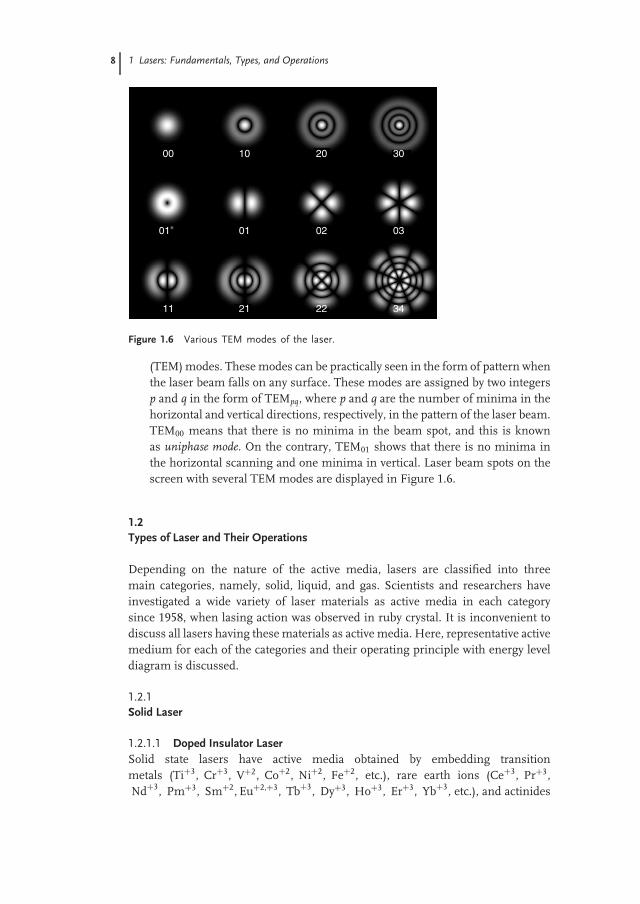
Figure 1.6 Various TEM modes of the laser.
(TEM) modes. These modes can be practically seen in the form of pattern whenthe laser beam falls on any surface. These modes are assigned by two integersp and q in the form of TEMpq, where p and q are the number of minima in thehorizontal and vertical directions, respectively, in the pattern of the laser beam.TEM00 means that there is no minima in the beam spot, and this is knownas uniphase mode. On the contrary, TEM01 shows that there is no minima inthe horizontal scanning and one minima in vertical. Laser beam spots on thescreen with several TEM modes are displayed in Figure 1.6.
1.2Types of Laser and Their Operations
Depending on the nature of the active media, lasers are classified into threemain categories, namely, solid, liquid, and gas. Scientists and researchers haveinvestigated a wide variety of laser materials as active media in each categorysince 1958, when lasing action was observed in ruby crystal. It is inconvenient todiscuss all lasers having these materials as active media. Here, representative activemedium for each of the categories and their operating principle with energy leveldiagram is discussed.
1.2.1Solid Laser
1.2.1.1 Doped Insulator LaserSolid state lasers have active media obtained by embedding transitionmetals (Ti+3, Cr+3, V+2, Co+2, Ni+2, Fe+2, etc.), rare earth ions (Ce+3, Pr+3,Nd+3, Pm+3, Sm+2, Eu+2,+3, Tb+3, Dy+3, Ho+3, Er+3, Yb+3, etc.), and actinides

1.2 Types of Laser and Their Operations 9
such as U+3 into insulating host lattices. Energy levels of active ions areonly responsible for lasing actions, while physical properties such as thermalconductivity and thermal expansivity of the host material are important indetermining the efficiency of the laser operation. Arrangement of host atomsaround the doped ion modifies its energy levels. Different lasing wavelength in theactive media is obtained by doping of different host materials with same active ion.Y3Al5O12, YAlO3, Y3Ga5O12, Y3Fe5O12, YLiF4, Y2SiO5, Y3Sc2Al3O12, Y3Sc2Ga3O12,Ti:Al2O3, MgAl2O4 (spinel), CaY4[SiO4]3O, CaWO4 (Scheelite), Cr:Al2O3, NdP5O4,NdAl3[BO3]4, LiNdP4O12, Nd:LaMgAl11O19, LaMgAl11O19, LiCaAlF6, La3Ga5SiO4,Gd3Sc2Al3O12, Gd3Ga5O12, Na3Ga2Li3F12, Mg2SiO4 (Forsterite), CaF2, Al2BeO4
(Alexandrite), and so on, are some of the important hosts. Active atom replaces anatom in the host crystal lattice. Nd:YAG is one of the best lasing material and isrepresentative of solid state lasing materials.
1.2.1.1.1 Dopant Energy Levels in the Host MatricesTransition metal and rare earth ions have partially filled and unfilled 3d and 4fsubshells, respectively. For example, the electronic configurations of trivalent Crand Nd ions are as follows:
Cr+3: 1s22s22p63s23p63d3
Nd+3: 1s22s22p63s23p63d104s24p64d104f35s25p6
There are unshielded partially filled d electrons in the transition metal ions, whilepartially filled 4f electrons of the rare earth ions are shielded by 5p and 5s sub shells.Owing to the electronic shielding of inner subshells in rare earth ions, crystal fieldeffect on the energy levels of transition metal ions are pronounced as compared tothat on energy levels of rare earth ions. When one of these ions is doped into a hostlattice, three main types of interactions occur: (i) columbic interaction betweenelectrons in the unfilled shell, (ii) the crystal field, and (iii) spin–orbit interactions.The columbic interaction between electrons causes splitting of energy levels of asingle electron configuration into several levels denoted by pair of values of L andS (L and S are vector sum of angular, l, and spin, s, momenta, respectively, ofelectrons). Crystal field splitting dominates for transition metal, while spin–orbitinteraction is the major contributor for rare earth ions in the modification of energylevel of isolated host atom. The energy level diagram for Cr+3:Al2O3 (ruby) andNd+3:YAG are displayed in Figure 1.7.
1.2.1.1.2 Pumping Techniques in Solid State LasersPumping of electrons from the ground state to the excited state to achievepopulation inversion condition is an essential requirement for lasing. Opticalpumping is the best and most efficient pumping method for solid state active mediadue to their broad optical absorption bands. A significant fraction of incident opticalenergy can be easily used for the pumping of ground state electrons using pulsed aswell as continuous light sources. Excess light energy raises temperature of the lasermaterials; therefore pulsed light sources are more suitable for dissipation of heat

10 1 Lasers: Fundamentals, Types, and Operations
(a) (b)
Energy (eV)
Energy (eV)
4T1 2.98
2T2 2.60
2E 1.79
2T1 1.86
4T2 2.20
4f3
4A2
3d
4F
4F
2G
2G
etc.
etc.
etc.
0
4I13/215/2
9/211/2 0.28
0.520.74
3/25/2
1.421.54
5/2 2.12
9/2 2.427/2 2.36
11/2 1.979/2 1.817/2 1.66
0
3
Figure 1.7 Energy level diagrams for doped insulator lasers: (a) ruby and (b) Nd:YAGlasers.
through circulating water jackets. Low-pressure quartz/glass-sealed krypton/xenonlamps are mostly used for pulsed pumping light sources, while tungsten halogenlamps and high-pressure mercury discharge lamps are utilized for continuousoptical pumping. An inductive, capacitive, and resistive (LCR) circuit and triggerunit as shown in Figure 1.8 is basically used for operating the flashtube. The detailcircuit diagram of the power supply is presented in Ref. [3]. High-voltage pulse ofthe trigger coil ionizes some gas in the tube and makes it conductive. This causesrapid discharge of the capacitor through the tube and generation of intense opticalradiation for almost few milliseconds. A small inductor in the series protectsdamage of the tube due to high capacitor discharge current. Light source and activemedium should be arranged in such a way that maximum pumping radiationfalls on the active medium. Active media in solid state lasers are cylindrical androd shaped with few millimeters diameter and few centimeter lengths. Severalarrangements of cylindrical flash lamp and rod-shaped active media are used foroptical pumping to get laser radiation. The flash lamp and active medium assemblyare placed inside gold-plated reflectors of circular or elliptical cross section. In thefirst practical operating laser, ruby rod was pumped by helical flash lamp inside thecylindrical reflecting cavity. Such arrangement has significant uniformity of irra-diation inside the rod but exhibits poor optical coupling. Side-by-side arrangementof flash lamp and laser rod inside the cylindrical gold-plated reflector or wrappingboth together with a metal foil are simpler approaches having good optical coupling

1.2 Types of Laser and Their Operations 11
Inductance
Current limitingresistor
Supply for capacitorcharging
Capacitor bank
Trigger coil
Figure 1.8 Trigger unit and LCR circuit diagram for solid state lasers.
but poor uniformity of irradiation. An elliptical reflector having flash lamp at onefocus and laser rod at the other focus is the most popular and best way of opticalpumping in the solid state lasers. Light radiation leaving from the first focus getsfocused close to the axis of laser rod placed at the second focus to make uniformenergy distribution. Combination of a number of elliptical reflectors having laserrod at the common foci and several flash lamps at the other foci is used for betteroptical pumping with more uniform energy distribution. Various geometries forthe arrangement of laser rod and flash lamps are illustrated in Figure 1.9. Nd:YAGlaser is widely used in the processing of materials and various characterizations.Here we discuss energy level diagram and operating principles of Nd:YAG lasers.
1.2.1.1.3 Nd:YAG Laser Construction and OperationThe schematic diagram of Nd:YAG laser head as shown in Figure 1.10, consistsof oscillator section, rear mirror, quarter-wave plate, Pockel cells, polarizer, pumpchambers, injection seeder, output coupler, D-Lok monitor, fold mirrors, amplifiersection, harmonic generator (HG), temperature controller, dichroic mirrors, andBeam Lock pointing sensor. It may have single or multipump chambers, andeach chamber consists of single or multiple flash lamps depending on the powerof laser. The laser head end panel contains coolant, output connector, coolantinput connector, neutral/ground connector, control cable connector, high-voltageconnector, Q-switch input connector, and nitrogen purge input connector. TheHGs have potassium di-hydrogen phosphate (KDP) and beta barium borate (BBO)crystals for frequency doubling and tripling, respectively. It can be operated in longpulse and Q-switch modes. Long pulse mode has light pulses of almost 200 μsduration and separated from each other by 2–4 μs. The total energy of the pulse

12 1 Lasers: Fundamentals, Types, and Operations
Flash lamps Laser rod
Laser rodLaser rod
Flash lamps
Flash lamps
Laser rod
Flash lamps
Figure 1.9 Different geometries for the arrangement of flash lamp and laser rod in solidstates lasers.
train is similar to that of a single Q-switched pulse. During Q-switched operation,the pulse width is less than 10 ns and the peak optical power is tens of megawatts.
The properties of Nd:YAG are the most widely studied and best understoodof all solid state laser media. Its energy level diagram, optical arrangements forQ-switching and stable and unstable resonators are depicted in Figure 1.11. Theactive medium is triply ionized neodymium, which is optically pumped by a flashlamp whose output matches principle absorption bands in the red and near infrared(NIR). Excited electrons quickly drop to the F3/2 level, the upper level of the lasingtransition, where they remain for a relatively longer time (∼230 μs). The strongesttransition is F3/2 → I11/2, emitting a photon in NIR region (1064 nm). Electronsin the I11/2 state quickly relax to the ground state, which makes its populationlow. Therefore, it is easy to build up a population inversion for this pair of stateswith high emission cross section and low lasing threshold at room temperature.There are also some other competing transitions at 1319, 1338, and 946 nm fromthe same upper state, but having lower gain and a higher threshold than the1064 nm wavelength. In normal operation, these factors and wavelength-selectiveoptics limit oscillation to 1064 nm. A laser comprising just an active medium andresonator will emit a pulse of laser light each time the flash lamp fires. However,the pulse duration will be long, about the same as the flash lamp and its peakpower will be low. When a Q-switch is added to the resonator to shorten the pulse,output peak power is raised dramatically. Owing to the long lifetime of F3/2, a large

1.2 Types of Laser and Their Operations 13
Amplifier
Harmonic generator (HG)
HG temperature controller
Dichroic mirror DM1(Static mount)
Dichroic mirror DM2(Piezo mount)
Base pan
Aluminumbase plate
BeamLokpointing sensor
PolarizerPockels cell(Q-Switch)
High reflector M1and l/4 plate
OscillatorInjection seeder
Pump chambers(4 places)
D-Lok monitor
Output coupler M2
Fold mirrorsFM1FM2
Figure 1.10 Assembly of various components in the head of an Nd:YAG laser system withfour pump chambers.
population of excited neodymium ions can build up in the YAG rod in a way similarto which a capacitor stores electrical energy. When oscillation is prevented for sometime to build up high level of population inversion by electro-optical Q-switchingand after that if the stored energy gets quickly released, the laser will emit a shortpulse of high-intensity radiation.
1.2.1.2 Semiconductor LaserSemiconductor lasers also known as quantum well lasers are smallest, cheapest, canbe produced in mass, and are easily scalable. They are basically p-n junction diode,which produces light of certain wavelength by recombination of charge carrierwhen forward biased, very similar to the light-emitting diodes (LEDs). LEDs possessspontaneous emission, while laser diodes emit radiation by stimulated emission.Operational current should be higher than the threshold value in order to attainthe condition of population inversion. The active medium in a semiconductordiode laser is in the form of junction region of 2 two-dimensional layers. Noexternal mirror is required for optical feedback in order to sustain laser oscillation.The reflectivity due to the refractive index differences between two layers or totalinternal reflection to the active media is sufficient for this purpose. The diodesend faces are cleaved, and parallelism of reflecting surfaces is assured. Junction

14 1 Lasers: Fundamentals, Types, and Operations
4I9/2
11502 cm−1
11502 cm−1
~6000 cm−1
~4000 cm−1
2526
2473
21462111
20292001
848
311197
134
0
4I11/2
4I13/2
4I13/2
4I11/2
4I9/2
4I15/2
4I15/2
4F3/2
4F3/2
Laser transition1064 nm
Laser transition1064 nm
Ground level
Pump bands
Quarter-waveplate
Highreflector
5 μs
4 kV
Pockelscell
Stable
Unstable
Polarizer
(a) (c)
(b)
Figure 1.11 (a) Energy level diagram for the transition of Nd:YAG laser (b) The Q-switchcomprises a polarizer, a quarter-wave plate, high quality reflector, and pockels cell, and (c)stable and unstable resonator configurations.
made from a single type of semiconductor material is known as homojunction,while that obtained from two different semiconductors is termed as heterojunction.Semiconductors of p and n type with high carrier density are brought togetherfor constructing p-n junction with very thin (≈1 μm) depletion layer. Figure 1.12illustrates GaAs homojunction semiconductor diode laser. Lasing occurs in theconfined narrow region, and optical feedback is done by reflections between cleavedend faces. For GaAs n = 3.6, therefore reflectivity R from the material–air interfaceis R = (n − 1)2/(n + 1)2 = 0.32, which is small but sufficient for lasing.
When the operating current is small, the population inversion built compensateslosses in the system and no lasing action is done. Increase of the current abovea critical value named as threshold current commences lasing action, and theintensity of laser radiation increases rapidly with further increase in the operatingcurrent. Semiconductor lasers have large divergence compared to any otherlaser systems, which is due to their small cross section of active region. Actualdimension (d) of the active medium is of the order of light wavelength (λ), whichcauses diffraction and hence divergence by an angle of θ ≈ λ/d. Homojunctionsemiconductor lasers have some disadvantages over heterojunction lasers. Both ofthe laser systems should have confinement of injected electrons and emitted lightin the junction region in order to initiate efficient stimulated emission process. In

1.2 Types of Laser and Their Operations 15
Rough surfaces
P+ GaAs
n + GaAs
Cleaved end surfaces
−
Laser output
Figure 1.12 Basic geometry of semiconductor laser system.
the homojunction laser, confinement of light is the consequence of the presenceof hole and electrons close to the junction. Homojunction lasers operate undersuch confinement mechanism but have high threshold current density and lowefficiency. Electrons have to travel different distances before they recombine withthe holes. In contrast, heterojunction lasers exhibit much higher lasing efficiencyand low threshold current density compared to their homojunction counterparts.Another difficulty with homojunction laser is to prevent the radiation fromspreading out sideways from the gain region, which causes loss instead of gain.Therefore they can only be used in the pulsed mode.
Heterojunction lasers are constructed by sandwiching a thin layer of GaAsbetween two layers of ternary semiconductor compound Ga1−xAlxAs withcomparatively lower refractive indices and higher band gap energy. Lowerrefractive indices of surrounding layers causes confinement of laser radiationinside the active medium by the mechanism of total internal reflection, whichmakes laser oscillation to sustain in the medium. Higher band gap energy of thesurrounding media creates potential barrier to prevent charge carriers to diffusefrom the junction region, that is, provides a way for the confinement of chargecarriers in the junction region, which enhances the condition of populationinversion and hence stimulated emission. The electrical circuit for pumping thesemiconductor diode lasers is similar to the doped insulator lasers.
1.2.2Gas Laser
Gas lasers are widely available in almost all power (milliwatts to megawatts) andwavelengths (UV-IR) and can be operated in pulsed and continuous modes. Basedon the nature of active media, there are three types of gas lasers viz atomic, ionic,and molecular. Most of the gas lasers are pumped by electrical discharge. Electronsin the discharge tube are accelerated by electric field between the electrodes. Theseaccelerated electrons collide with atoms, ions, or molecules in the active media and

16 1 Lasers: Fundamentals, Types, and Operations
Power supply
Gas-filled discharge tube
M1M2 Prism
Figure 1.13 Construction of gas laser system (argon ion laser with prism-based wavelengthtuning).
induce transition to higher energy levels to achieve the condition of populationinversion and stimulated emission. An example of gas laser system is shown inFigure 1.12.
1.2.2.1 Atomic Gas Laser; He:Ne LaserHe–Ne laser is the simplest and representative of atomic gas lasers. The activemedium is a 10 : 1 mixture of He and Ne gases filled in a narrow tube of fewmillimeter diameters and 0.1–1 m long at a pressure of about 10 Torr. Dischargetube and circuit are very similar as shown in Figure 1.13. A resistant box isused in series with power supply in order to limit the discharge current becausetube resistance falls too low once discharge is initiated. Energy levels of Ne atomare directly involved in the laser transitions, and He atoms provide an efficientexcitation mechanism to the Ne atoms. Helium atoms from their ground state 11S,are pumped to the excited atomic states 21S and 23S by impact with acceleratedelectrons in the discharge tube. Neon atoms have 3s and 2s atomic states, whichare closer to the 21S and 23S states of the helium atoms, respectively. Collisionbetween excited helium atoms in the 21S and 23S states and neon atoms in theground states reinforce transfer of energy from helium to neon atoms. Heliumatoms in the 21S and 23S states excite neon atoms from ground state to the 3sand 2s states, respectively, and return to the ground state. Excited states 3s and2s of Ne atom have longer life times as compared to its lower (3p and 2p states),therefore they serve as metastable states and are used in achieving the condition ofpopulation inversion between s and p states. Transitions 3s → 3p, 3 s → 2p, and2 s → 2p of neon atoms are consequences of lasing at 3.39 μm, 632.8 nm, and1.15 μm wavelengths, respectively. Lifetimes of 3p and 2p atomic states are shorter;therefore Ne atoms from these states rapidly decay to the 1s state by nonradiativetransitions. Neon atoms in the 1s state go to the ground state after losing energythrough collision with the wall of the tube. The energy level diagram of the He–Nelaser is displayed in Figure 1.14. Another important atomic laser is copper vaporlaser, but it is beyond the scope of this book.

1.2 Types of Laser and Their Operations 17
Neon
NeonGround statesHelium
Wall collision
FastFast
1s
2s
3s
2p
3p
23S
21S
Ele
ctro
n ex
cita
tion
Atomic collision
Atomic collision
1.15 μm
3.39 μm
632.8 nm
Figure 1.14 Energy level diagram for He–Ne laser system.
1.2.2.2 Ion Laser: Argon Ion Laser
1.2.2.2.1 Physical ConstructionArgon ion laser is one of the widely used ion gas lasers, which typically generatesseveral watts power of a green or blue output beam with high beam quality. Thecore component of an argon ion laser is an argon-filled tube made of ceramics,for example, beryllium oxide, in which an intense electrical discharge betweentwo hollow electrodes generates a plasma with a high density of argon (Ar+) ions.A solenoid around the tube (not shown in Figure 1.13) is used for generating amagnetic field, which increases output power of the beam by magnetic confinementof the plasma near the tube axis.
A typical device, containing a tube with a length of the order of 1 m, cangenerate 2.5–5 W of output power of laser beam in the green spectral region at514.5 nm, using several tens of kilowatts of electric power. The dissipated heatis removed with a chilled water flow around the tube. The laser can be switchedto other wavelengths such as 457.9 nm (blue), 488.0 nm (blue–green), or 351 nm(ultraviolet) by rotating the intracavity prism. The highest output power is achievedon the standard 514.5 nm line. Without an intracavity prism, argon ion lasers have atendency for multiline operation with simultaneous output at various wavelengths.
1.2.2.2.2 Working of Ar Ion LaserThe argon ion laser is a four level laser, which facilitates to achieve populationinversion and low threshold for lasing. The neutral argon atoms filled betweentwo hollow electrodes inside the plasma tube (Figure 1.13) are pumped to the 4penergy level by two steps of collisions with electrons in the plasma. The first stepionizes atoms to make ions in the 3p (E1) state, and the second one excites theseions from the ground state E1 either directly to the 4p4 levels (E3) or to the 4p2
levels (E4), from which it cascades almost immediately to the 4p2 (E3). The 4p ions

18 1 Lasers: Fundamentals, Types, and Operations
IonizationElectron - ionrecombination bycollision
3/2
1/2
7/2
5/2
3/21/2
5/2
3/2
3/2
1/2
½A
r ionground state
Ar atom
ground state
Radiative decay ≈ 72 nm
4P4D0
4P2S0
4P2P0
4P2D0
4S2P
528.7
514.5
457.
9
454.
546
5.0
472.
048
8.0
496.5
478.
5
Figure 1.15 Energy level diagram for argon ion laser system.
eventually decay to 4s levels (E2), either spontaneously or when stimulated to do soby a photon of appropriate energy. The wavelength of the photon depends on thespecific energy levels involved and lies in between 400 and 600 nm. The ion decaysspontaneously from 4s to the ground state, emitting a deep ultraviolet photon ofabout 72 nm. There are many competing emission bands as shown in Figure 1.15.These can be preferentially selected using a prism in front of one of the endmirrors. This prism selects a specific wavelength to send it back through the cavityto stimulate identical emissions, which stimulates more and more emissions andmake regenerative process. This facilitates laser to operate at a single wavelength.Removal of the prism allows for broadband operation, that is, several wavelengthsare kept rather than keeping only a particular wavelength. The mirrors reflect anumber of lines within a maximum range of about 70 nm. Energy level diagramshowing various transitions of Ar ion laser is illustrated in Figure 1.15.
1.2.2.3 Molecular LaserUnlike isolated atoms and ions in atomic and ionic lasers, molecules have wideenergy bands instead of discrete energy levels. They have electronic, vibrational,

1.2 Types of Laser and Their Operations 19
and rotational energy levels. Each electronic energy level has a large number ofvibrational levels assigned as V, and each vibrational level has a number of rotationallevels assigned as J. Energy separation between electronic energy levels lies in theUV and visible spectral ranges, while those of vibrational–rotational (separationsbetween two rotational levels of the same vibrational level or a rotational level ofone vibrational level to a rotational level from other lower vibrational level) levels,in the NIR and far-IR regions. Therefore, most of the molecular lasers operate inthe NIR or far-IR regions.
1.2.2.3.1 Carbon Dioxide (CO2) LaserCarbon dioxide is the most efficient molecular gas laser material that exhibits for ahigh power and high efficiency gas laser at infrared wavelength. It offers maximumindustrial applications including cutting, drilling, welding, and so on. It is widelyused in the laser pyrolysis method of nanomaterials processing. Carbon dioxide isa symmetric molecule (O=C=O) having three (i) symmetric stretching [i00], (ii)bending [0j0], and (iii) antisymmetric stretching [00k] modes of vibrations (insetof Figure 1.16), where i, j, and k are integers. For example, energy level [002] ofmolecules represents that it is in the pure asymmetric stretching mode with 2units of energy. Very similar to the role of He in He–Ne laser, N2 is used asintermediately in CO2 lasers. The first, V = 1, vibrational level of N2 moleculelies close to the (001) vibrational level of CO2 molecules. The energy differencebetween vibrational levels of N2 and CO2 in CO2 laser is much smaller (0.3 eV)as compared to the difference between the energy levels of He and Ne (20 eV) inHe–Ne laser; therefore comparatively larger number of electrons in the dischargetube of CO2 laser having energies higher than 0.3 eV are present. In addition to
Collisions
Nitrogen Carbon dioxide0.4
0.3
0.2
0.1
Pumping
V = 1
Ene
rgy
(eV
)
Laser transitions
CollisionsCollisional deactivation(via helium) andradiative decay
Collisional deactivation(via helium) andradiative decay
P10R10
001
9.6 μm10.6 μm
100 020
010
10
1191
Figure 1.16 (a) Absorption, emission curves, and (b) energy level diagram of dye lasersystem.

20 1 Lasers: Fundamentals, Types, and Operations
this, V = 1 state of N2 is metastable, which provides longer time for the collisionbetween excited N2 molecules and the ground state CO2 molecules to excite themto (001) state. These two favorable conditions make it easy to attain high level ofpopulation inversion between 001 and 100, and 020 vibrational states of CO2.
Transitions between 001 initial level to 100 and 020 final vibrational states makestimulated emissions of several IR radiations between 9.2 and 10.6 μm wavelengths.Helium gas is also mixed in the gas mixture in order to increase efficiency of lasing.Helium helps in transporting waste heats to the tube wall and de-exciting (100) and(020) energy levels by collision process. The amounts of N2, CO2, and He in CO2
laser depends on the type and application of system, but usually, the amount ofnitrogen and CO2 molecules are comparable, while helium concentration is higherthan either. Low pressure (∼10 Torr) is generally used for CW lasers, while quitehigher pressure is used for high-energy and pulsed laser applications. Dependingon power level and beam quality of CO2 lasers, various internal structures arebeing used, and they are called sealed tube laser, gas flow laser, transversally excitedatmospheric (TEA) laser, and gas dynamic laser. Detailed discussions of these arebeyond the scope of the book, although interested readers may consult Ref. [4].
In the far-IR region of 10 μm wavelength, the usual optical material has largeabsorbance and therefore cannot be used as windows and reflecting mirrors in thecavity. Materials such as Ge, GaAs, ZnS, ZnSe, and some alkali halides havingtransparency in the IR region are used.
1.2.2.3.2 Nitrogen LaserLasing transition in N2 laser takes place between two electronic energy levels,therefore this laser operates in the ultraviolet region at 337 nm wavelength. Here,upper electronic level has a shorter lifetime compared to the lower one, hence CWoperation cannot be achieved, but pulsed operation with narrow pulse width ispossible. The pulse width is narrow because as soon as lasing starts, population ofthe lower state increases, while that at upper state decreases and rapidly a state atwhich no lasing is possible is rapidly achieved. Such a laser system is known asself-terminating.
1.2.2.3.3 Excimer LasersExcimers are molecules such as ArF, KrF, XeCl, and so on, that have repulsiveor dissociating ground states and are stable in their first excited state. Usually,there are less number of molecules in the ground state; therefore direct pumpingfrom ground state is not possible. Molecules directly form in the first excitedelectronic state by the combination of energetic halide and rare gas ions. Conditionof population inversion can be easily achieved because the number of moleculesin the ground state is too low as compared to that in the excited state. Lasingaction is done by transition from bound excited electronic state to the dissociativeground state. Population in the ground state always remains low because moleculesdissociate into atoms at this point. Usually a mixture of halide such as F2 and raregas such as Ar is filled into the discharge tube. Electrons in the discharge tubedissociate and ionize halide molecules and create negative halide ions. Positive

1.2 Types of Laser and Their Operations 21
Ar+ and negative F− ions react to produce ArF∗ molecules in the first excitedbound state, followed by their transition to the repulsive ground state to commencelasing action. Various excimer lasers are developed in the wavelength range of120–500 nm with 20−15% efficiency and up to 1 J peak and 200 W average powers.These lasers are widely used in materials processing and characterizations as wellas for the pumping of dye lasers.
1.2.3Liquid Laser
Liquids are more homogeneous as compared to solids and have larger density ofactive atoms as compared to the gasses. In addition to these, they do not offer anyfabrication difficulties, offer simple circulation ways for transportation of heat fromcavity, and can be easily replaced. Organic dyes such DCM (4-dicyanomethylene-2-methyl-6-p-dimethylaminostyryl-4H-pyran), rhodamine, styryl, LDS, coumarin,stilbene, and so on, dissolved in appropriate solvents act as gain media. Whenthe solution of dye molecules is optically excited by a wavelength of radiationwith good absorption coefficient, it emits radiation of longer wavelength, knownas fluorescence. The energy difference between absorbed and emitted photonsis mostly used by nonradiative transitions and creates heat in the system. Thebroader fluorescence band in dye/liquid lasers facinates them with the uniquefeature of wavelength tuning. Organic dye lasers, as tunable and coherent lightsources, are becoming increasingly important in spectroscopy, holography, andin biomedical applications. A recent important application of dye lasers involvesisotope separation. Here, the laser is used to selectively excite one of severalisotopes, thereby inducing the desired isotope to undergo a chemical reactionmore readily. The dye molecules have singlet (S0, S1, and S2) and triplet (T1 andT2) group of states with fine energy levels in each of them (Figure 1.17). Singlet
450 500 550 600
Absorption band
Triplet absorption
band
Emission band
Em
issi
on a
nd a
bsor
ptio
n
Wavelength (nm)
Emission
ExcitationForbidden
Absorption
Absorption
Single statesTriplet states
Incr
easi
ng e
nerg
y
S0
S1
S2
A
a
B
b
T2
T1
Intersystemcrossing
CharacteristiclifetimesB → a 5 × 10⁻⁵ s
B → T 5 × 10−0 s
T → S 10−7 to 10−3 s
λ
(a) (b)
Figure 1.17 Energy level diagram for carbon dioxide (molecular) laser system. Inset showsthree mode of vibration of CO2 molecule.

22 1 Lasers: Fundamentals, Types, and Operations
and triplet states correspond to the zero and unit values of total spin momentumof electrons, respectively. According to selection rules for transitions in quantummechanics, singlet–triplet and triplet–singlet transitions are quite less probableas compared to the transitions between two singlet or two triplet states. Opticalpumping of dye molecules initially at the bottom of S0 state transfers them to thetop of S1 state. Collisional relaxation of these molecules takes them to the bottomof S1 state, from where they transit to the top of S0 state with stimulated emissionof radiation. Most of the states in the complex systems are usually neither puresinglet nor pure triplet. Singlet states have small contribution of triplet and viceversa. In the case of most of the dye molecules, unfortunately, T1 state lies justbelow the S1, therefore few molecules transit from S1 to T1 by losing some energythrough nonradiative transitions. Difference between T1 and T2 states is almostsame as the wavelength of lasing transition, therefore emitted lasing radiation getsabsorbed, which reduces laser gain and may cease the laser action. Therefore, someof the dye lasers operate in the pulsed mode with the pulse duration shorter thanthe time required to attain a significant population in the state T1. Some of thedyes also absorb laser radiation corresponding to the transition from S1 to uppersinglet transitions. Therefore, one should select the dye molecule so that energydifferences between these states do not lie between the ranges of laser radiation.
1.3Methods of Producing EUV/VUV, X-Ray Laser Beams
EUV and VUV coherent light sources, that is, EUV/VUV lasers, are in high demandin order to continue the validity of Moore’s law in future, in the high-density datawriting on disks, materials synthesis and characterizations, and spectroscopic in-vestigations. For example, in photolithography for making the micro/nanopatternson microelectronic chips, the width of the pattern is proportional to the wavelengthof laser light used. Therefore, we would reach a limit for further miniaturizationof electronic devices, which causes failure of the well-known Moore’s law if shorterwavelength lasers would not be developed. Similarly, for data writing on the opticaldiscs, if we have shorter wavelength lasers, larger amount of data can be writtenon the same size of disc. In addition to these, such sources are the future of3D high-density data writing, microscopy at the atomic scale, crystallography, andmedical sciences. Following are the methods for developing short wavelength lasers.
1.3.1Free Electron Lasers (FEL)
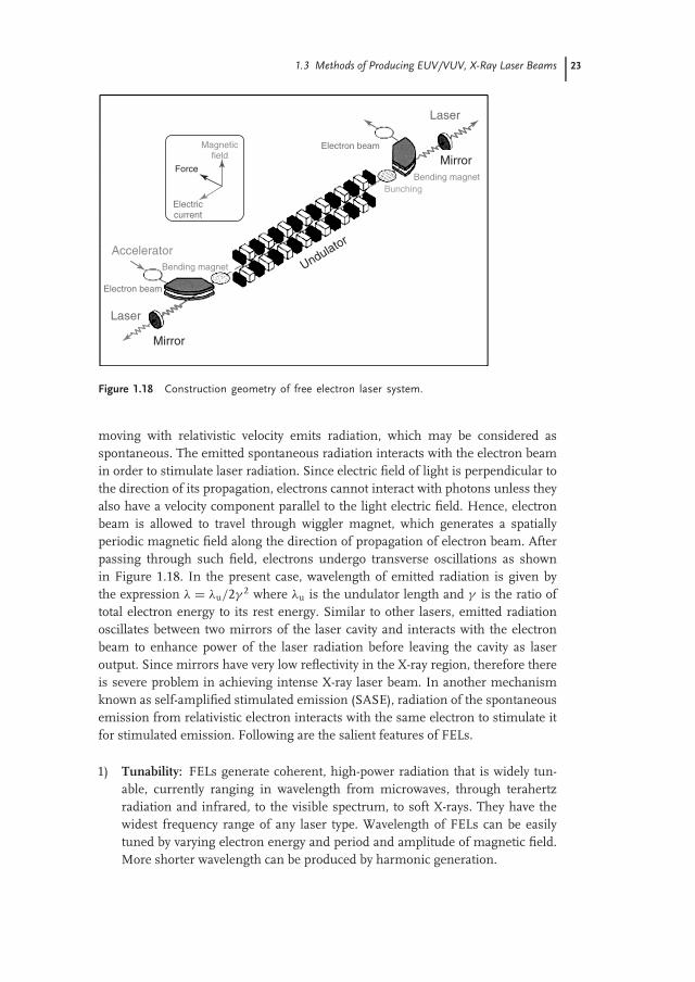
In contrast to the other laser sources, free electron lasers (FELs) have an activemedium that consists of a beam of free electrons, propagating at relativisticvelocities in a spatially periodic magnet (undulator). Here, electrons experience theLorentz force, execute transverse oscillations, and emit synchrotron radiation inthe forward direction (Figure 1.18). We know that an accelerated charged particle
1.3 Methods of Producing EUV/VUV, X-Ray Laser Beams 23
Laser
Laser
Mirror
Mirror
Bending magnet
Magneticfield
Bending magnet
Accelerator
Bunching
Electron beam
Electron beam
Electriccurrent
Undulator
Force
Figure 1.18 Construction geometry of free electron laser system.
moving with relativistic velocity emits radiation, which may be considered asspontaneous. The emitted spontaneous radiation interacts with the electron beamin order to stimulate laser radiation. Since electric field of light is perpendicular tothe direction of its propagation, electrons cannot interact with photons unless theyalso have a velocity component parallel to the light electric field. Hence, electronbeam is allowed to travel through wiggler magnet, which generates a spatiallyperiodic magnetic field along the direction of propagation of electron beam. Afterpassing through such field, electrons undergo transverse oscillations as shownin Figure 1.18. In the present case, wavelength of emitted radiation is given bythe expression λ = λu/2γ 2 where λu is the undulator length and γ is the ratio oftotal electron energy to its rest energy. Similar to other lasers, emitted radiationoscillates between two mirrors of the laser cavity and interacts with the electronbeam to enhance power of the laser radiation before leaving the cavity as laseroutput. Since mirrors have very low reflectivity in the X-ray region, therefore thereis severe problem in achieving intense X-ray laser beam. In another mechanismknown as self-amplified stimulated emission (SASE), radiation of the spontaneousemission from relativistic electron interacts with the same electron to stimulate itfor stimulated emission. Following are the salient features of FELs.
1) Tunability: FELs generate coherent, high-power radiation that is widely tun-able, currently ranging in wavelength from microwaves, through terahertzradiation and infrared, to the visible spectrum, to soft X-rays. They have thewidest frequency range of any laser type. Wavelength of FELs can be easilytuned by varying electron energy and period and amplitude of magnetic field.More shorter wavelength can be produced by harmonic generation.

24 1 Lasers: Fundamentals, Types, and Operations
2) Pulse duration: Based on the electron beam time structure pulse durationranges from CW to ultrashort pulsed regime (fraction of picoseconds)
3) Coherence: It is transverse and longitudinal for oscillators and coherent seedamplifiers, while only transverse for SASE
4) Brilliance: Depending on the status of the art of the electron beam technology,the FEL brilliance can be larger, in some spectral regions (in particular inVUV-X), by many orders of magnitude than the brilliance of the existingsources (lasers and synchrotron radiation).
We do not go into much details, but interested readers are referred to Refs.[6–11].
1.3.2X-Ray Lasers
X-ray lasers provide coherent beam of electromagnetic radiation with the wave-length range from ∼30 nm down to ∼0.01 nm. The first X-ray laser beam wasinitiated in 1980 by underground nuclear explosion at Nevada test site, while thefirst laboratory demonstration of X-ray laser was made in 1984 in the form ofNova laser. Most of the experimental demonstration of light amplification in thisspectral range has come from the high-density plasma produced by interaction ofhigh-energy laser with the solid target. Like the above case of FEL, unavailabilityof good-quality of cavity mirrors has utilized the mechanism of SASE in X-raylasers. In such case intensity of the laser beam depends on the amplifier length.Gain of the active medium depends on the mass and temperature of the ionsand multiplicity and population of the upper/lower levels. Most of the X-ray lasersutilize transitions among L, M, N, and so on, shells of highly ionized atoms. Theshort life times of the excited states (picoseconds) require very large pumpingrates in order to achieve and maintain the condition of population inversion.Laser produced plasmas (LPPs) have high electron temperatures (∼0.1–1.0 keV)and densities (∼1018–21 cm−3), which is required for higher degree of ionizationand excitation in X-ray lasers. Therefore LPPs are used as primary medium forX-ray lasers. In addition to these, LPPs have uniform density and temperature andthus can provide good media for amplification and propagation of X-rays. Of thevarious processes suggested, two main (i) collisional excitation and (ii) electronrecombination are responsible for attaining the population inversion condition. Incase of collisional excitation upper state of the lasing has lower probability of decaywith dipole radiation, compared to the lower state, which creates the conditionof population inversion between them. In contrast, the rate of population at anystate by three-body recombination process is proportional to the forth power of theprinciple quantum number. The combination of preferential population of upperlevels and fast radiative decay of lower states leads to an inversion amongt theN = 2, 3, 4, . . . states [12].

1.3 Methods of Producing EUV/VUV, X-Ray Laser Beams 25
1.3.3EUV/VUV Lasers through Higher Harmonic Generation
Higher harmonic generation (HHG) is a nonlinear optical process used for thegeneration of shorter wavelength laser light from the interaction of high-intensitylonger wavelength lasers source with nonlinear optical medium. The obtained newfrequencies are integral multiples (nω) of the fundamental (ω) frequency of originallaser light. This phenomenon was first observed in 1961 by Franken et al. [13] withruby laser and quartz as nonlinear medium. The first HHG result was found in1988, which shows that intensity of the spectra decreases with the increase of order,reaches a plateau, where the intensity remains constant for several orders, andfinally ends abruptly at a position called high harmonic cutoff . They are portablesources of EUV/soft X-rays, synchronized with the fundamental laser and operatedat the same frequencies with much shorter pulse width. These are more spatiallycoherent compared to X-ray lasers and cheaper than FELs. The harmonic cutoffincreases linearly with increasing laser intensity up to the saturation intensityIsat where harmonic generation stops. The saturation intensity can be increasedby changing the atomic intensities of lighter noble gases, but these have lowerconversion efficiency. HHG strongly depends on the driving laser field; thereforethe produced harmonics have similar spatial and temporal coherence. Owing tothe phase matching and ionization conditions required for HHG, the producednew pulses are with shorter pulse duration compared to the driving laser. Mostly,harmonics are produced in very short time frame, when phase matching conditionis satisfied. Instead of shorter temporal window, they emit colinearly with thedriving laser pulse and have very tight angular confinement. Gaseous media andLPP on the solid surfaces are two sources used as nonlinear active media for thegeneration of harmonics.
The shortest wavelength producible with the harmonic generation is givenby cutoff of the plateau, which is given by the maximum energy gained byionized electron from the light electric field. The energy of cutoff is given byEmax = IP + 3.17UP, where UP is the pondermotive potential from the laser fieldand IP is the ionization potential. It is assumed that electron is initially producedby ionization into the continuum with zero initial velocity and is accelerated bythe laser electric field. After half period of the laser electric field, direction ofmotion of electron is reversed and it is accelerated back to the parent nuclei. Afterattaining high kinetic energy of the order of hundreds of electron volts (dependingon the intensity of laser field), when electron enters into the parent nuclei, it emitsBremsstrahlung-like radiation during a recombination process with the atoms as itreturns back to the ground state. The three-step model of ionization, acceleration ofelectron, and its recombination with parent nuclei by the emission of EUV photonsis shown in Figure 1.19.
Wide wavelength ranges of laser systems starting from hundreds of micrometers(molecular liquid lasers) to X-ray regions (FELs, X-ray lasers, and HHG lasers) withCW and pulsed lasers having various pulse width from milliseconds to attosecondsand repletion rates from single pulse to the megahertz are available nowadays.

26 1 Lasers: Fundamentals, Types, and Operations
Propagation
x0
wb
wEUV
Ionization
Ene
rgy
Laser electric field
tb
t
Recombination
Figure 1.19 Three-step model of ionization and acceleration of electron and its recombina-tion with parent nuclei by the emission of EUV photons.
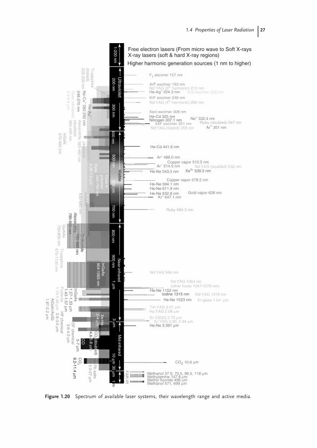
Figure 1.20 represents the spectrum of available laser system with wavelengthrange and active media.
1.4Properties of Laser Radiation
Light produced from the lasers have several valuable characteristics not shown bylight obtained from other conventional light sources, which make them suitablefor a variety of scientific and technological applications. Their monochromaticity,directionality, laser line width, brightness, and coherence of laser light make themhighly important for various materials processing and characterization applications.These properties are discussed separately in the following subsections.
1.4.1Monochromaticity
Theoretically, waves of light with single frequency ν of vibration or single wave-length λ is termed as single color or monochromatic light source. Practically, nosource of light including laser is ideally monochromatic. Monochromaticity is arelative term. One source of light may be more monochromatic than others.Quantitatively, degree of monochromaticity is characterized by the spread in fre-quency of a line by ν, line width of the light source, or corresponding spreadin wavelength λ. For small value of λ, frequency spreading, ν, is given asν = −(c/λ2)λ and λ = (c/ν2). The most important property of laser is itsspectacular monochromaticity. Based on the type of laser media, solid, liquid, orgas and molecular, atomic, or ions, and the type of excitation, produced laser lineconsists of color bands that range from broad (as dye laser λ ∼ 200) to narrow(for gas discharge lines, λ ∼ 0.01 nm). Utilizing suitable filters one can get themonochromaticity as good as a single line of lasing transition. But such a singleline also contains a set of closely spaced lines of discrete frequencies, known as laser
1.4 Properties of Laser Radiation 27
Cr:fluoride
Alexandrite
780-850 nm
780-800 nm
Methanol 37.9, 70.5, 96.5, 118 μm
Methanol 571, 699 μm
CO2 10.6 μm
Methyl fluoride 496 μmMethylamine 147.8 μm
Free electron lasers (From micro wave to Soft X-raysX-ray lasers (soft & hard X-ray regions)
Higher harmonic generation sources (1 nm to higher)
F2 excimer 157 nm
KrF excimer 248 nm
ArF excimer 193 nm
Xecl excimer 308 nm
XeF excimer 351 nm
Nd:YAG (4th harmonic) 266 nm
Nd:YAG (tripled) 355 nm
Nd:YAG (doubled) 532 nm
Nd:YAG 946 nm
Er:glass 1.54 μm
Er:YSG 2.90, 2.94 μmEr:YSGG 2.79 μm
Tm:YAG 2.01 μmHo:YAG 2.08 μm
Nd:YAG 1319 nm
Nd:YAG 1064 nm(other hosts 1047-1079 nm)
Nd:YAG (5th harmonic) 213 nmHe-Ag+ 224.3 nm Krcl excimer 222 nm
Nitrogen 337.1 nmHe-Cd 325 nm
He-Ne 543.5 nm
He-Ne 632.8 nm
He-Ne 1523 nm
He-Ne 3.391 μm
He-Ne 1152 nm
He-Ne 611.9 nmHe-Ne 594.1 nm
He-Cd 441.6 nm
Ruby (doubled) 347 nm
Ruby 694.3 nm
Ar+ 351 nm
Ar+ 488.0 nm
Ar+ 514.5.nm
Kr+ 647.1.nm
Ne+ 332.4 nm
Copper vapor 510.5 nm
Gold vapor 628 nm
Copper vapor 578.2 nm
Xe3+ 539.5 nm
Iodine 1315 nm
FA
R-IR
1-200 nm200 nm
300 nm400 nm
500 nm
Visible600 nm
700 nm800 nm
900 nm1 μm
3 μm10 μm
30 μm1 m
Ultraviolet
Near-infrared
Mid-infrared
Pb salts
3.3-27 μmT
i:sapphire(tripled)235-330 nm
He-A
u+
Ne-C
u+ 282-292 nm
248-270 nmC
O2
CO
2 (doubled)
5-7 μm
9.2-11.4 μm
CO
4.6- 5.8 μm
Xe-H
e2-4 μm
HF
chemical
2.6-3.0 μm
DF
chemical
3.6-4.0 μm
InGaA
s
GaA
lAs
InGaA
lP
InGaN
370-493 nm
InGaA
s904-1065 nm
1.43-1.57 μm1.27-1.33 μm
1.13-1.36 μmF
osteriteT
i:sapphire
Ti:sapphire
(doubled)360-460 nm
Cr:fluoride
Alexandrite
Alexandrite
(doubled)360-400 nm
670-1130 nm
780-850 nm
780-800 nm
AlG
aln/AsS
b1.87-2.2 μm
750-850 nm
630-685 nm
Dyes
Dyes in
polymer
550-700 nm
0.38-1.0 μm
Dyes (doubled)
0.2-0.4 μm
Figure 1.20 Spectrum of available laser systems, their wavelength range and active media.

28 1 Lasers: Fundamentals, Types, and Operations
modes (Figure 1.5). Suppressing all other modes excluding the central intense modeusing mode locking one can increase monochromaticity of laser line. Suppressingof modes is possible by increasing the separation (νsep = c/2L) between twomodes, which can be done by reducing the cavity length. When the axial mode sep-aration approaches the line width, ν, of the lasing transition it is possible that onlysingle mode oscillates. Now, the line width of the laser is equal to that of the singlelongitudinal mode, which is too narrow. The width of the laser line is directly relatedto the quality factor Q of the cavity and is given by Q = ν/ν. The quality factorQ actually defines (Q = 2π × energy stored in the resonator at resonance/energydissipated per cycle) the ratio of energy stored in the cavity at resonance conditionand energy dissipated per cycle. High degree of monochromaticity of laser lineis required in the diagnosis of closely spaced rotational levels of molecules usingselective excitation of that level. The laser line would be absolutely monochromaticif it is oscillating with single frequency, that is, width of the laser line is zero(ν = 0). The single-mode laser has the highest degree of monochromaticity, butit has also not achieved the ideal monochromaticity condition.
1.4.2Directionality
One of the most striking properties of laser is its directionality, that is, its output isin the form of an almost parallel beam. Owing to its directional nature it can carryenergy and data to very long distances for remote diagnosis and communicationpurposes. In contrast, conventional light sources emit radiation isotropically;therefore, very small amount of energy can be collected using lens. Beam of anideal laser is perfectly parallel, and its diameter at the exit window should be sameto that after traveling very long distances, although in reality, it is impossible toachieve. Deviation in the parallelism of practical laser beam from the ideal is notdue to any fault in the laser design, but due to diffraction from the edges of mirrorsand windows. From the theory of diffraction, we know that circular aperture hasangle of diffraction given by θ = sin−1(1.22λ/D). The spreading of the beam doesdepend on the physical nature of aperture and on the type of transverse modeoscillating inside the cavity. In the particular case of TEM00 mode oscillating insidethe nearly confocal cavity, the value of minimum diameter at the center of cavityis given by w0 = (λr/2π )1/2, where r is the radius of curvature of cavity mirrors(Figure 1.3). The beam diameter, w, varies with distance, z, from the point ofminimum diameter and is given by w = w0(2z/r). The beam radius at any pointinside and outside the cavity is determined by the distance from the cavity axiswhere intensity reduces 1/e times of its maximum value.
1.4.3Coherence
Coherence is one of the striking properties of the lasers, over other conven-tional sources, which makes them useful for several scientific and technological

1.4 Properties of Laser Radiation 29
applications. The basic meaning of coherence is that all the waves in the laser beamremain spatially and temporarily in the same phase. Photons generated throughstimulated emission are in phase with the stimulating photons. For an ideal lasersystem, electric field of light waves at every point in the cross section of beamfollows the same trend with time. Such a beam is called spatially coherent. Thelength of the beam up to which this statement is true is called coherence length (LC)of the beam. Another type of coherence of the laser beam is temporal coherence,which defines uniformity in the rate of change in the phase of laser light waveat any point on the beam. The length of time frame up to which rate of phasechange at any point on the laser beam remains constant is known as coherencetime (tC). Let P1 and P2 be two points on the same laser beam at time t and t + τ .The correlation function between phases at these two points is termed as mutualcoherence function, which is a complex number with magnitude between 0 and 1 (0for completely incoherent beam and 1 for ideally coherent). Coherence time (tC) isalso defined as the time taken by the atoms/molecules in active medium to emit alight wave train of length LC. These two coherences are thus related by tC = LC/c.The coherence time of the laser beam is almost inverse (tC � 1/ν) of the width,ν, of the laser transition. The lasers operating in the single mode (well-stabilizedlasers) have narrow line width, therefore they exhibit higher coherence time andcoherence length compared to those operating in multimode. Spatial and temporalcoherences of continuous laser beams are much higher compared to those ofpulsed laser systems because temporal coherence in the pulse lasers are limited bythe presence of spikes within the pulse or fluctuation in the frequency of emission.
1.4.4Brightness
Lasers are more intense and brighter sources compared to other conventionalsources such as the sun. A 1 mW He–Ne laser, which is a highly directionallow divergence laser source, is brighter than the sun, which is emitting radiationisotropically. Brightness is defined as power emitted per unit area per unit solidangle. In the particular case of 1 mW He–Ne laser with 3.2 × 10⁻⁵ rad beamdivergence and 0.2 mm spot diameter at exit window the solid angle (π (3.2 × 10⁻⁵)2)is 3.2 × 10⁻⁹ sr and spot area (π (2 × 10⁻⁴)2) at the exit window is 1.3 × 10⁻⁷m2.Thus the brightness of the beam is given by ((1 × 10⁻³)/(1.3 × 10−7 m2 × 3.2 ×10−9 sr)) = 2.4 × 10¹² W/m−2 sr−1, which is almost 106 times brighter than thesun (1.3 × 10⁶ W/m−2 sr−1).
1.4.5Focusing of Laser Beam
In practice, every laser system has some angle of divergence, which increases thespot size of laser beam and reduces its brightness. If a convergent lens of suitablefocal length is inserted in the path of the laser beam, it focuses laser energy into
30 1 Lasers: Fundamentals, Types, and Operations
small spot area at focal point. If wL is the radius of the beam and f is the focallength of convergent lens, then radius of the spot at focal point is given asrs = λf /πwL, where λ wavelength of laser radiation. If D is the lens diameterand the whole aperture is illuminated by laser radiation (i.e., wL = D/2) thenrs = 2λf /πD or rs = 2λF/π , where F = f /D is f number of the lens.
In the case of a particular Nd:YAG laser operating at 1064 nm wavelength and35 mJ/pulse energy, and 10 ns pulse width. It is focused by a convex lens ofF = 5, and whole of the lens area is illuminated by laser. The spot diameter atthe focal point is given by rs = 2 × 1.064 × 10−6 × 5/π = 3.4 μm. The irradianceof the laser beam is given by I = E(J)/pulse width (s) × (πr2
s ) = 35 × 10−3/(10 ×10−9 s × π (3.4 × 10⁻⁶)2) ≈ 1016 W m−2.
1.5Modification in Basic Laser Structure
Addition of some electronic, optical, or electro-optical systems between the activemedia and mirror to modify the pulse width, pulse shape, and energy/pulseand generation of integral multiple of laser frequency is important for advancedtechnological applications. Mode locking or phase locking, Q-switching, pulseshaping, pulse compression and expansion, frequency multiplication, and so on,are some commonly used methods in advanced laser technology.
1.5.1Mode Locking
1.5.1.1 Basic Principle of Mode LockingMode locking is a technique in optics by which a laser can be made to produce lightpulses of extremely short duration of the order of picoseconds (10−12 s) or femtosec-onds (10−15 s). The basis of this technique is to induce constant phase relationshipbetween the modes of laser cavity. Simply, same phase of δ can be chosen for all lasermodes. Such a laser is called mode-locked or phase-locked laser, which produces a trainof extremely narrow laser pulses separated by equal time intervals. Let N modes areoscillating simultaneously in the laser cavity with (A0)n, ωn, and δn being the ampli-tude, angular frequency, and phase of the nth mode. All these parameters vary withtime, therefore modes are incoherent. The output of such laser is a linear combi-nation of n different modes and is given by A(t) = ∑N
n=0 (A0)nei(�nt+δn) expression.For simplicity, frequency of the nth mode can be written as ωn = ω − nω, whereωn is the mode with highest frequency and ω = cπ/L is the angular frequencyseparation between two modes. If all the modes have same amplitude and weforce the various modes to maintain same relative phase δ to one another, thatis, we mode lock the laser such that δn = δ, then the expression for resultantamplitude will be A(t) = A0ei(� t+δ) ∑N
n=0 e−iπnct/L = A0ei(� t+δ)sin(Nφ/2)/sin(φ/2),where φ = πct/L. The irradiance of the laser output is given by I(t) = A(t)A(t)∗ =A2
0sin2(Nφ/2)/sin2(φ/2), which is the periodic function of the period φ = 2π in

1.5 Modification in Basic Laser Structure 31
the time interval t = 2L/c (time of round-trip inside the cavity). The maximumvalue of irradiance is N2A2
0 at φ = 0 or 2pπ (p is integer). Irradiance has zerovalue for Nφ/2 = pπ , where p is an integer with values neither zero nor a multipleof N. This makes φ = 2pπ/N = πct/L or t = (1/N)(2L/c)p. Therefore, separationbetween two consecutive minima, that is, pulse width of a single laser pulse ist = (1/N)(2L/c). Hence, the output of a mode-locked laser has sequence of shortpulses of pulse duration (1/N)(2L/c) separated in time by 2L/c. The ratio of pulseseparation to the pulse width is equal to the number of modes N, which shows thatthere should be a large number of modes in the cavity in order to get high-powershort duration (picoseconds and femtoseconds) laser pulses.
1.5.1.2 Mode Locking Techniques
1.5.1.2.1 Active Mode LockingWe have discussed that mode locking is achieved by inducing the longitudinalmode to attain the fixed phase relationship, which may be exploited by varying theloss of the laser cavity at a frequency equal to the intermode separation c/2L. Let usconsider a shutter between the active medium and output mirror, which is closed formost of the time and is opened after every 2L/c seconds (corresponding to the timeof round-trip) and remains open for short duration of (1/N)(2L/c) seconds. If thelaser pulse train is as long as the shutter remains opened and arrives at the shutterexactly at the time of its opening, the pulse train is unaffected by the presence ofshutter. The segment of the pulse, which arrives before opening and after closingof the shutter, will be clipped. Thus phase relationship of the modes is maintainedby periodic oscillation of the shutter. An electro-optical or acousto-optical crystaloperating on the principle of Pockels or Kerr effect respectively, may be used as aperiodic shutter.
In the former case of electro-optical switching, a polarizer and an electro-opticalcrystal are arranged in between the active medium and laser exit mirror so that laserbeam passes through the polarizer before entering into the crystal. Laser light fromthe active medium passes through the polarizer and gets plane polarized. Whenthis polarized beam passes twice through the crystal (with appropriate electricfield along the direction of light propagation) before returning to the polarizer,the plane of polarization is rotated by an angle of 90◦, which does not allow thelight beam to enter into the active media through the polarizer. In other words, theshutter is effectively closed. If there is no field along the crystal in the direction ofpropagation of light, there will be no rotation of the plane of polarization of lightand it can pass though the polarizer and enter into the active medium (shutter isopen). Similarly in acousto-optical switching, a 3D grating pattern is establishedin a medium (water or glass, not active medium of lasing) by the incident andreflected sound waves created by piezoelectric transducer attached at one end ofthe medium. This grating diffracts a part of the laser beam and creates a highloss.

32 1 Lasers: Fundamentals, Types, and Operations
1.5.1.2.2 Passive Mode LockingPassive mode locking method consists of placing a saturable absorber inside thecavity. Saturable absorbers are molecules having a nonlinear decrease in absorptioncoefficients with the increase in the irradiance of light. The saturable absorber isplaced between active laser medium and mirror. If an intense pulse of lightpasses through the saturable absorber placed inside the laser cavity, the low-powertails (weaker modes) of the pulse are absorbed because of the absorption of dyemolecules. The high-power peak of the pulse is, however, transmitted because thedye is bleached. Owing to this nonlinear absorption, the shortest and most intensefluctuation grows, while the weaker dies out.
1.5.2Q-Switching
Q-switching, sometimes known as giant pulse formation, is a technique by whicha laser can be made to produce a pulsed output beam. The technique allows theproduction of light pulses with extremely high (of the order of approximatelygigawatts) peak power, much higher than would be produced by the same laser if itwere operating in a CW mode. Compared to mode locking, another technique forpulse generation with lasers, Q-switching leads to much lower pulse repetition rates,much higher pulse energies, and much longer pulse durations. Both techniques aresometimes applied at once. In contrast to mode locking, where we achieve a trainof pulses, Q-switching provides a single strong and short pulse of laser radiation.
Q-switching is achieved by putting a variable attenuator inside the laser’s op-tical resonator. When the attenuator is functioning, light that leaves the gainmedium does not return and lasing cannot begin. This attenuation inside thecavity corresponds to a decrease in the Q factor or quality factor of the opticalresonator. A high Q factor corresponds to low resonator losses per round-trip,and vice versa. The variable attenuator is commonly called a ‘‘Q-switch,’’ whenused for this purpose. Initially the laser medium is pumped while the Q-switchis set to prevent feedback of light into the gain medium (producing an opticalresonator with low Q). This produces a population inversion, but laser operationcannot yet occur since there is no feedback from the resonator. Since the rate ofstimulated emission is dependent on the amount of light entering the medium,the amount of energy stored in the gain medium increases as the medium ispumped. Owing to losses from spontaneous emission and other processes, aftera certain time, the stored energy will reach some maximum level; the mediumis said to be gain saturated. At this point, the Q-switch device is quickly changedfrom low to high Q, allowing feedback and the process of optical amplificationby stimulated emission to begin. Because of the large amount of energy alreadystored in the gain medium, the intensity of light in the laser resonator buildsup very quickly; this also causes the energy stored in the medium to be de-pleted almost as quickly. The net result is a short pulse of light output from

1.5 Modification in Basic Laser Structure 33
the laser, known as a giant pulse, which may have very high peak intensity. Sim-ilar to mode locking, active and passive techniques are used for Q-switching.Electro-optical and opto-acoustic (active Q-switching) switches, and saturable ab-sorbers (passive Q-switching) are used to prevent feedback signal into the activemedia.
1.5.3Pulse Shaping
Pulse shaping is a technique of optics, which modifies temporal profile of a pulsefrom laser. It may lengthen or shorten pulse duration, can generate complexpulses, or generate multiple pulses with femtosecond/picosecond separation froma single laser pulse. A pulse shaper may act as a modulator. Modulating functionis applied on the input pulse to get the desired pulse. The modulating functionin pulse shapers may be in time or a frequency domain (obtained by Fouriertransform of time profile of pulse). In the pulse shaping methods optical signalis converted into electronic signal, where the presence and absence of pulsesare designated by 1 and 0, respectively. There are two well-known pulse shap-ing techniques (i) direct space to time pulse shaper (DST-PS) and (ii) Fouriertransform pulse shaper (FT-PS). In DST-PS, electrical analog of the desired out-put signal is used as a modulator with the electrical analog of input pulses. Incontrast to DST-PS, the FT-PS uses a modulating function, which is a Fouriertransform of the required sequence. In other words, a specific temporal sequenceof pulses, the modulating function, is its Fourier transform and acts in frequencydomain.
Optical design is a common experimental arrangement consisting of a combi-nation of two sets of grating, a pair of mirrors, a pair of convex lenses, and apulse shaper (see Figure 1.21a). By placing different types of optical componentswe can design various types of laser pulses. For example, employing suitablefilter at focal plane can remove optical radiation of undesired frequency. A slabof transparent material with varying thickness can offer different path lengths fordifferent frequency components and can decide which component of light willcome out first. A concave lens at the focal plane provides longer path length forhigher frequency component, and vice versa (Figure 1.21b). This causes the lowerfrequency component to come first and the higher frequency one comparativelylater, resulting in positively chirped1) output pulse (frequency increases with time).In contrast to this, a planoconvex or biconvex lens makes longer path length forlower frequency, and vice versa, which makes higher frequency to come out firstand shorter frequency after that, that is, negative chirped output. Both positive andnegative chirping lengthens the pulse duration, that is, stretching of the laser pulse.Removing or reducing the chirp causes compression (reduction of pulse duration)of the pulse.
1) Chirping is a mechanism by which different components of light frequency of a pulse fromlaser comes out at different time. When frequency of light components of pulse increaseswith time it is called positive chirping, decreases with time negative chirping and if constantwith time no chirping (un-chirped).

34 1 Lasers: Fundamentals, Types, and Operations
Focalplane
Focalplane
Originalpulses
Originalpulses
Outputpulse
Grating Grating
Grating Grating
Focalplane
Originalpulses
Outputpulse
Outputpulse
Grating Grating
f f
f f f f f f f f
f f(a)
(c)(b)
Figure 1.21 (a) Basic optical geometries for laser pulse shaping, (b) positive chirped, and(c) negative chirped pulse shaping.
References
1. Wilson, J. and Hawkes, J.F.B. (eds)(1987) Lasers: Principles and Applica-tions, Prentice Hall Publications. ISBN:013523697-5.
2. O’Shea, D.C., Callen, W.R., and Rhodes,W.T. (eds) (1977) Introduction to Lasersand their Applications, Addison-WesleyPublishing Company, Inc., Philippines.ISBN: 020105509-0.
3. Ifflander, R. (ed.) (2001) Solid StateLaser Material Processing: Fundamen-tal Relations & Technical Realizations,Springer-Verlag, Berlin, Heidelberg.ISBN: 354066980-9.
4. Weber, M.J. (ed.) (1991) Handbook ofLaser Science and Technology, CRC Press,Boca Raton, FL, Ann Arbor, MI, Boston,MA. ISBN: 084933506-X.
5. Letokhov, V.S., Shank, C.V., Shen, Y.R.,and Walther, H. (eds) (1991) Interactionof Intense Laser Light with Free Elec-trons, M.V. Fedorov; Laser Science andTechnology and International Handbook,Harwood Academic Publishers GmbH,Switzerland. ISBN-3718651262.
6. Dattoli, G. and Renieri, A. (1984) Ex-perimental and theoretical aspects ofFree-Electron Lasers, in Laser Handbook,
vol. 4 (eds M.L. Stich and M.S. Bass),North Holland, Amsterdam.
7. Marshall, J.C. (1985) Free Electron Lasers,Mac Millan Publishing Company,New York.
8. Luchini, P. and Motz, H. (1990) Undu-lators and Free-Electron Lasers, ClaredonPress, Oxford.
9. Colson, W.B., Pellegrini, C., andRenieri, A. (eds) (1990) Laser Hand-book, Free-Electron Lasers, vol. 6, NorthHolland, Amsterdam.
10. Brau, C.A. (1990) Free-Electron Lasers,Academic Press, Oxford.
11. Dattoli, G., Renieri, A., and Torre, A.(1995) Lectures in Free-Electron Laser The-ory and Related Topics, World Scientific,Singapore.
12. Dunn, J., Osterheld, A.L., Shepherd,R., White, W.E., Shlyaptsev, V.N., andStewart, R.E. (1998) Demonstration ofx-ray amplification in transient gainnickel-like palladium scheme. Phys. Rev.Lett., 80 (13), 2825–2828.
13. Franken, P.A., Hill, A.E., Peters, C.W.,and Weinreich, G. (1961) Generationof optical harmonics. Phys. Rev. Lett., 7,118.