1. coordinate power requirements with electrical contractor
TRANSCRIPT

SHOP SUBMITTAL / DRAWING REVIEW
RESPONSE
Project Name: DPARD Admin Offices From: Chuck Stringer
Project No: 13333
Description: 238129.01 DX Split System Submittal
SW Associates Consulting Engineers
Engineer’s review is for general compliance with the design concept and contract documents. Markings or comments or the lack there of shall not be construed as relieving the Contractor from compliance with the project plans and specifications. The Contractor remains responsible for details and accuracy, for confirming and correlating all quantities and dimensions, for selecting fabrication processes, for techniques of construction, for performing this work in a safe manner and for coordinating his work with that of other trades This review does not constitute approval or acceptance of deviations from contract documents, such deviations if any must be requested in writing or clearly identified as deviations in accordance with contract documents.
No Exception Taken
Make Corrections Noted
Revise and Submit
Rejected
SWA Project No. 13333 Submittal No: 238129.01
Date: 04-19-19
Checked By: Chuck Stringer
Comments: 1. Coordinate power requirements with electrical contractor.
SW Associates Consulting Engineers 5429 LBJ Freeway Suite 300 LB129 Dallas, TX 75240 www.swaengineers.com Tel 1.214.397.0211 Fax 1.214.397.0886
Formerly Consulting Engineers

SUBMITTAL TRANSMITTAL
CONTRACTOR’S REVIEW STAMP A/E REVIEW STAMP
SUBMITTAL DATA
Project Dallas Park & Rec Dept Admin Offices Location 10031 E. Northwest Highway Dallas, TX 75238
General Contractor DENCO CONSTRUCTION SPECIALISTS
Trade HVAC
Items Submitted VRF Split-System
Supplier Total HVAC Phone 214-926-8260
Substitutions and Deviations
Remarks
I CERTIFY THAT THE ABOVE ITEM DESCRIBED IN THE ATTACHED SUBMITTAL COMPLIES WITH THE CONTRACT
DOCUMENTS EXCEPT AS NOTED ABOVE.
Shawnee Hallmark 972-226-2609 ext. 108 3-20-19
NAME (TRADE) PHONE NO. DATE
Review Comments:
DENCO CONSTRUCTION SPECIALISTS
SHOP DRAWING AND SUBMITTAL REVIEW
JOB NO. DPA-238129
DATE 3-20-19
REVIEWER Shawnee Hallmark
Corrections or comments made relative to submittals during this review
do not relieve the subcontractor from compliance with the requirements
of the drawings and specifications. This check is only for review of
general conformance with the design concept of the project and general
compliance with the information given in the contract documents. The
subcontractor is responsible for conforming and correlating all
quantities and dimensions, selecting fabrication processes and
techniques of construction, coordinating his work with that of other
trades and performing his work in a safe and satisfactory manner.
THIS REVIEW DOES NOT INDICATE NOR IMPLY ANY APPROVAL
OF CHANGES TO TIME OR CHANGES IN COSTS

FOR REVIEW
YORK SUBMITTAL DATA
FOR
Dallas Parks and Recreation
Administration Offices Dallas, TX
Owner: City of Dallas Mechanical Engineer: SWA Mechanical Contractor: Total HVAC
Date: 4/3/2019 Revision: Original Submitted By: Kia Kohen, Texas AirSystems, Inc. Equipment Manufacturer: LG Equipment Type: Heat Pump Split System Unit Tags: AHU/CU-1

FOR REVIEW
York Split Systems Tags: AHU/HP-1 One (1) York Heat pump split system utilizing R410A designed for 208-230V/3Ph/60Hz and complete as follows: Outdoor Unit:
Galvanized steel construction with pre-painted finish Single stage compressor Copper tube / Aluminum fin condenser coil Sweat connections
Indoor Unit: EC motor DX evaporator coils Galvanized steel drain pan TXV Kit – Field installed by others 2” Pleated Filters Electric auxiliary heat 7-Day programmable thermostat – Field installed by others
Notes and Exclusions: 1. Unloading, rigging, installation, wiring, STARTUP, & refrigerant piping are not included
and are by others. 2. The above pricing does not include Line sets, housekeeping pads, low ambient controls,
interconnecting piping, sensors, BAS/EMS controls, smoke detectors, or disconnect switches.

Date04/03/2019Project NameDPARD Administrative OfficesProject Number0403191034Client / PurchaserChris Bentley
Submittal Summary Page Qty Tag # Model # Description1 HP-1 YHE18B21S York Brand, 1.5 Ton, Heat Pump, R-410A Refrigerant, 14 SEER / 1-
Stage, 208/230-1-60
1 AHU-1 AE18BX21 1.5 Ton, Single Piece Air Handler, Standard Multi-Position ECMMotor, 17.5" Cabinet Width, 208/230-1-60, Flex - Coils
1 S1-1TVMBA1 KIT,TXV,R-410A,3/4 INCH CHATLEFF CO
1 S1-6HK16500506 5 kW 208/230-1-60 Electric Heat Kit with Circuit Breaker
1 320003 8064 - 60A NON-FUSED PULLOUT DISCONNECT
1 TH6220U2000 T6 PRO 2H/2C CONV/2H/1C HP
WARNING: Cancer and Reproductive Harm - www.P65Warnings.ca.gov
Equipment start-up and commissioning by a factory trained technician is recommended.Contact your supplying distributor or sales representative for additional information & guidance.
Unitary Sales Tool v1.5.9.0 Information is subject to change without notice. Check local codes. Printed 04/03/2019

Cooling PerformanceTotal gross capacity 17.3 MBHSensible gross capacity 12.8 MBHSeasonal Efficiency (at ARI) 15.25 SEEREfficiency (at ARI) 12.75 EERAmbient DB temp. 105.0 °FPower input 1.74 kW
RefrigerantRefrigerant type R-410A
Heat Pump PerformanceHeating output capacity (Max) 19.3 MBHAmbient DB temp. 47 °FLeaving DB temp. 89.8 °FAir temp. rise 29.8 °FPower input 1.45 kW
Outside/Mixed AirOutside Air Cfm 50 CFM
Electrical Data Power supply 208/230-1-60 Unit min circuit ampacity 12 AmpsUnit max over-current protection 20 Amps
Dimensions & WeightHgt 37 in. Len 31 in. Wth 31 in.Weight with factory installed options 120 lbs.
Matchup InformationARI Reference Number 8915248 ARI Rated Capacity 18 MBHARI Rated Efficiency 15.25 SEERNote: Please refer to the tech guide for listed maximum static pressures
1.5 TonProduct Features• The YHE models are the newest offering in our successful LX Series splitsystem heat pump lineup. These outdoor units are optimized for the new 14SEER / 8.2 HSPF Minimum Efficiency in all US Regions, and are specificallydesigned to be matched with York indoor coils, furnaces, and air handlers toprovide a complete system solution.
Unit Features• 14 SEER / 1-Stage• Environmentally Friendly - CFC-free R-410A refrigerant deliversenvironmentally friendly performance with zero ozone depletion.
• Durable Finish – The coated steel wire fan guard, coated external fasteners,and pre-treated G90-equivalent galvanized steel chassis components resistcorrosion and rust creep. Champagne colored powdercoat paint furtherprotects external panels.
• Fully Exposed Refrigerant Connections and a Single Panel Covering theElectrical Controls Make for Easy Servicing of the Unit
• Protected Compressor - Compressors are protected internally by a highpressure relief valve and a temperature sensor, and externally by the systemhigh and low pressure switches. The liquid line filter-drier is factory installedto protect the compressor against moisture and debris
• Rugged Coil Protection -Coils are protected from mechanical damage by aproven stamped steel coil guard design in all US Regions, and arespecifically designed to be matched with York indoor coils, furnaces, and airhandlers to provide a complete system solution.
Warranty• Five (5) Year Limited Parts Warranty• Ten (10) Year Limited Compressor Warranty• Extended Ten (10) Year Limited Parts Warranty when Product is RegisteredOnline Within 90 Days of Purchase for Replacement or Closing for NewHome Construction
Unitary Sales Tool v1.5.9.0 Information is subject to change without notice. Check local codes. Printed 04/03/2019
LX Series14 SEER / 8.2 HSPF
Page: 3
Project Name: DPARD Administrative Offices Unit Model #: YHE18B21SQuantity: 1 Tag #: HP-1 System: YHE18B21S, AE18BX21

Factory Installed Options
YHE18B21S
Equipment Options Option(s) Selected|
Product Category: Y York Brand Type: H Heat Pump Nominal Series Efficiency & Staging: E 14 SEER / 1-Stage Nominal Cooling Capacity: 18 1.5 Ton Refrigerant: B R-410A Refrigerant Voltage: 2 208/230-1-60 Product Generation: 1 Factory-Installed Options: S
Field Installed Accessories
S1-1TVMBA1 - KIT,TXV,R-410A,3/4 INCH CHATLEFF CO(2.0 lbs)
Unitary Sales Tool v1.5.9.0 Information is subject to change without notice. Check local codes. Printed 04/03/2019
LX Series14 SEER / 8.2 HSPF
Page: 4
Project Name: DPARD Administrative Offices Unit Model #: YHE18B21SQuantity: 1 Tag #: HP-1 System: YHE18B21S, AE18BX21

YHE Unit Dimensions
Unitary Sales Tool v1.5.9.0 Information is subject to change without notice. Check local codes. Printed 04/03/2019
LX Series14 SEER / 8.2 HSPF
Page: 5
Project Name: DPARD Administrative Offices Unit Model #: YHE18B21SQuantity: 1 Tag #: HP-1 System: YHE18B21S, AE18BX21

YHE Installation
Unitary Sales Tool v1.5.9.0 Information is subject to change without notice. Check local codes. Printed 04/03/2019
LX Series14 SEER / 8.2 HSPF
Page: 6
Project Name: DPARD Administrative Offices Unit Model #: YHE18B21SQuantity: 1 Tag #: HP-1 System: YHE18B21S, AE18BX21

YHE Wiring Diagram
Unitary Sales Tool v1.5.9.0 Information is subject to change without notice. Check local codes. Printed 04/03/2019
LX Series14 SEER / 8.2 HSPF
Page: 7
Project Name: DPARD Administrative Offices Unit Model #: YHE18B21SQuantity: 1 Tag #: HP-1 System: YHE18B21S, AE18BX21
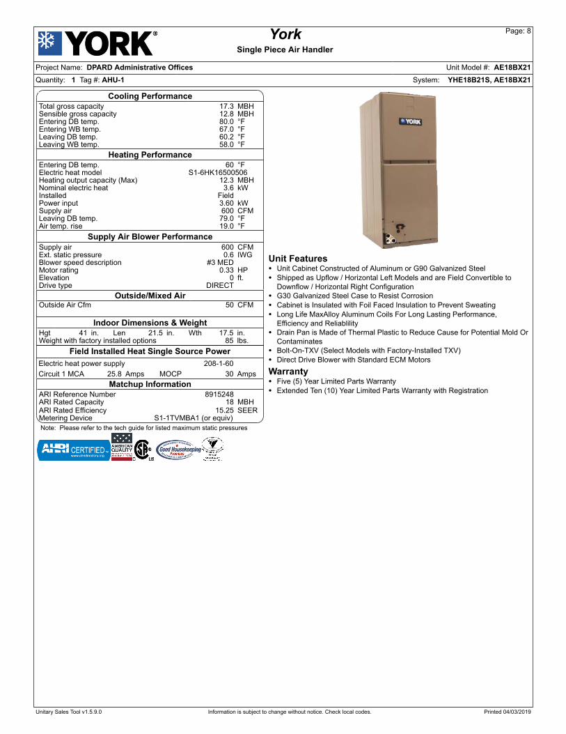
Cooling PerformanceTotal gross capacity 17.3 MBHSensible gross capacity 12.8 MBHEntering DB temp. 80.0 °FEntering WB temp. 67.0 °FLeaving DB temp. 60.2 °FLeaving WB temp. 58.0 °F
Heating PerformanceEntering DB temp. 60 °FElectric heat model S1-6HK16500506Heating output capacity (Max) 12.3 MBHNominal electric heat 3.6 kWInstalled Field Power input 3.60 kWSupply air 600 CFMLeaving DB temp. 79.0 °FAir temp. rise 19.0 °F
Supply Air Blower PerformanceSupply air 600 CFMExt. static pressure 0.6 IWGBlower speed description #3 MED Motor rating 0.33 HPElevation 0 ft.Drive type DIRECT
Outside/Mixed AirOutside Air Cfm 50 CFM
Indoor Dimensions & WeightHgt 41 in. Len 21.5 in. Wth 17.5 in.Weight with factory installed options 85 lbs.
Field Installed Heat Single Source PowerElectric heat power supply 208-1-60 Circuit 1 MCA 25.8 Amps MOCP 30 Amps
Matchup InformationARI Reference Number 8915248 ARI Rated Capacity 18 MBHARI Rated Efficiency 15.25 SEERMetering Device S1-1TVMBA1 (or equiv) Note: Please refer to the tech guide for listed maximum static pressures
Unit Features• Unit Cabinet Constructed of Aluminum or G90 Galvanized Steel• Shipped as Upflow / Horizontal Left Models and are Field Convertible toDownflow / Horizontal Right Configuration
• G30 Galvanized Steel Case to Resist Corrosion• Cabinet is Insulated with Foil Faced Insulation to Prevent Sweating• Long Life MaxAlloy Aluminum Coils For Long Lasting Performance,Efficiency and Reliablility
• Drain Pan is Made of Thermal Plastic to Reduce Cause for Potential Mold OrContaminates
• Bolt-On-TXV (Select Models with Factory-Installed TXV)• Direct Drive Blower with Standard ECM MotorsWarranty• Five (5) Year Limited Parts Warranty• Extended Ten (10) Year Limited Parts Warranty with Registration
Unitary Sales Tool v1.5.9.0 Information is subject to change without notice. Check local codes. Printed 04/03/2019
YorkSingle Piece Air Handler
Page: 8
Project Name: DPARD Administrative Offices Unit Model #: AE18BX21Quantity: 1 Tag #: AHU-1 System: YHE18B21S, AE18BX21

Factory Installed Options
AE18BX21
Equipment Options Option(s) Selected|
Product Type: A Single Piece Air Handler Product Category: E Standard Multi-Position ECM Motor Capacity: 18 1.5 Ton Cabinet Width: B 17.5" Cabinet Width Refrigerant / TXV: X Flex - Coils Voltage: 2 208/230-1-60 Product Generation: 1
Field Installed Accessories
S1-1TVMBA1 - KIT,TXV,R-410A,3/4 INCH CHATLEFF CO(2.0 lbs)
S1-6HK16500506 - 5 kW 208/230-1-60 Electric Heat Kit with CircuitBreaker (5.0 lbs)
Unitary Sales Tool v1.5.9.0 Information is subject to change without notice. Check local codes. Printed 04/03/2019
YorkSingle Piece Air Handler
Page: 9
Project Name: DPARD Administrative Offices Unit Model #: AE18BX21Quantity: 1 Tag #: AHU-1 System: YHE18B21S, AE18BX21

Typical Application
TYPICAL APPLICATIONS
UPFLOW
HORIZONTAL RIGHT
HORIZONTAL LEFT
HEAT
TA
EH
HE
AT
DOWNFLOW
HEAT
Unitary Sales Tool v1.5.9.0 Information is subject to change without notice. Check local codes. Printed 04/03/2019
YorkSingle Piece Air Handler
Page: 10
Project Name: DPARD Administrative Offices Unit Model #: AE18BX21Quantity: 1 Tag #: AHU-1 System: YHE18B21S, AE18BX21

Unit Dimensions
DIMENSIONS & DUCT CONNECTION DIMENSIONS
G
A
1-1/2”
7-11/32”
C
FILTER ACCESS
DRAIN CONNECTIONSREFRIGERANT CONNECTIONS
BLOWERCOMPARTMENT 12-3/16”
E
BOTTOM INLETDIMENSIONS
TOP OUTLETDIMENSIONS
SERVICEDISCONNECTPANEL
B 20-1/2”
21-7/16”
F
COILCOMPARTMENT
18-5/8” D
Dimensions
Models
Dimensions1 Wiring Knockouts2 Refrigerant ConnectionsLine SizeA B
C D EF G
ropaVdiuqiLlortnoCrewoPhtdiWthgieHAE18BX21 41 17-1/2 12-7/8 14-1/4 16-1/2
7/8” (1/2”)1-3/8”(1")
1-23/32” (1-1/4”)7/8” (1/2”) 3/8”
3/4”AE24BX21 41 17-1/2 12-7/8 14-1/4 16-1/2AE30BX21 47-1/2 17-1/2 19-1/2 14-1/4 16-1/2AE36BX21 47-1/2 17-1/2 19-1/2 14-1/4 16-1/2AE36CX21 51-1/2 21 22-5/8 17-3/4 20AE42CX21 51-1/2 21 22-5/8 17-3/4 20
7/8”AE48CX21 51-1/2 21 22-5/8 17-3/4 20AE48DX21 55-1/2 24-1/2 26-5/8 21-1/4 23-1/2AE60CX21 55-3/4 21 26-7/8 17-3/4 20AE60DX21 55-1/2 24-1/2 26-5/8 21-1/4 23-1/2
1. All dimensions are in inches.2. Actual size (Conduit size in parenthesis.).
Unitary Sales Tool v1.5.9.0 Information is subject to change without notice. Check local codes. Printed 04/03/2019
YorkSingle Piece Air Handler
Page: 11
Project Name: DPARD Administrative Offices Unit Model #: AE18BX21Quantity: 1 Tag #: AHU-1 System: YHE18B21S, AE18BX21

Wiring Diagram
WIRING DIAGRAM
XFORMER
BLK/WHT
RED/WHT
BLU
BLU
GRN
L2
L1
L2
L1
HE1HE2 LSLS
HE3LS
H
H
FLFL
FL
3
1
5
4
SEQ2 SEQ1
RED/WHT
EQUIPMENTGROUND
YEL
BRN
YEL
BLKRED
BRN
WHT
BLU
PRP
BLU
RED
BLU
BLU
1
2
3
4
5
6
L2
L1
L2
L1
HE1
HE2
LS
LS
HE3LS
H
H
FL
FL
FL
3
1
5
4
SEQ1
RED/WHT
EQUIPMENTGROUND
BLU
BLKBLK
RED
RED
BRN
WHT
BLU
PRP
BLU
BLU
H
H
3
1
5
4
SEQ2
BLUL2
L1
BLU
HE5LS FL HE4 LSFL
BRN
BLK
BLK
YEL
YEL
YEL
RED
RED
RED
HE4 LSFL
H
H
3
1
5
4
BLU
BLK
BLU
L2
L1
RED/WHT
EQUIPMENTGROUND
YEL
BLK
WHT
BLU
PRP
YEL
BLU
HE1LS
FL
EQUIPMENTGROUND
BLK
RED/WHT
{
208-240 VAC 60HZ
1 PHASE SUPPLY
WHEN INSTALLING HEATER KIT, BE SURE THE BLOWER SPEED IS
SET TO THE SPEED SPECIFIED FOR THE AIR HANDLER/HEATER KIT
COMBINATION ON THIS UNIT'S INSTALLATION INSTRUCTIONS.
HEATER KITS: 6HK*65002066HK*6500506
HEATER KITS: 6HK*65018066HK*6502006
HEATER KIT:6HK*6502506
24V
240VCOM
208V
XFORMER
GRN
WHT
BRN
USE COPPER CONDUCTORS ONLY.IF ALUMINUM CONDUCTORS ARE PRESENT,ALL APPLICABLE LOCAL AND NATIONALCODES MUST BE FOLLOWED.
SEE INSTALLATION INSTRUCTIONS FOR PROPER
LOW VOLTAGE FIELD WIRING CONNECTIONS.
LEGENDLS - LIMIT SWITCHSEQ - SEQUENCERHE - HEATING ELEMENTFL - FUSIBLE LINKH - SEQUENCER HEATERRLY - RELAY
HH
HH
HH
AIR HANDLER - WITH NO HEAT KITWIRING DIAGRAM
5001016-UWD-A-0415
10 KW AND BELOW
1
2
3
4
5
6
1
2
3
4
5
6
L2
L1
HE2LS
FL
RLY 2 RLY 1
RED/WHT
EQUIPMENTGROUND
YEL
BLK
BLU
YEL
WHT
BLU
PRP
BLU
BLU
HE1LS
FL
WHT
HEATER KITS: 6HK*65008066HK*6501006
1
2
3
4
5
6
13 KW AND ABOVE
24V
240VCOM
208V1
2
3
4
5
6
1
2
3
4
5
6
BLOWERMOTOR
C
L
G
N
1 2 3 4 5
YEL
GRN
RED
BLU
WHT
BRN
BLU/W
HT
RED
BLK
RED/WHT
BLK/WHT
BLOWERMOTOR
C
L
G
N
1 2 3 4 5
208-240 VOLT
RESISTOR
FUSE
RED
TO OUTSIDE UNIT
BLU
RLY
BLU
BLU
BLU
YEL
YEL
RLY 2 RLY 1
YEL
BLKBLK
BLK
RED
RED
BLU
YEL
WHT
BLU
H
H
3
1
5
4
SEQ3
YEL
BRN
BLU
RLY 2 RLY 1
BLU
WHT
RED BLK
BLK
BLU
BLK
RED
BLK
SEQ or RLY
SEQ or RLY
HE5LS FL
HE4LS FL
HE3LS FL
HE2LS FL
HE1LS FL
RED
YELOD UNIT CONTACTOR
BLU
SEQ or RLY
SEQ or RLY
SEQ or RLY SEQ or RLY
SEQ or RLY
SEQ or RLY
SEQ or RLY
SEQ or RLY
HEATER KITS:6HK*65013066HK*6501506
L2
L1
L2
L1
HE1
HE2LS
LS
HE3LS FL
FL
FL
SEQ2 SEQ1
RED/WHT
EQUIPMENTGROUND
BLK
RED
YEL
BLK
REDBLK
BRN
WHT
BLU
PRP
BLU
YEL
BLU
1
2
3
4
5
6
RLY
BLU
BLU BLU
YEL
BLU
YEL
BRN
3
1
5
4 H
H
3
1
5
4
H
H
Unitary Sales Tool v1.5.9.0 Information is subject to change without notice. Check local codes. Printed 04/03/2019
YorkSingle Piece Air Handler
Page: 12
Project Name: DPARD Administrative Offices Unit Model #: AE18BX21Quantity: 1 Tag #: AHU-1 System: YHE18B21S, AE18BX21

Power Wiring Blower Speed Connection
POWER WIRING - LINE CONNECTIONS
GND.
FIELD POWER WIRING(208/230V)
NO ELECTRIC HEAT
COMPONENT CODES
CKT - CIRCUITCN - WIRE CONNECTOR/NUTGND - GROUND LUGSD - SERVICE DISCONNECTPOWER
SUPPLYCN
CN
GND
JUMPER BAR
SINGLE SOURCE POWER MULTI-SOURCE POWERSINGLE-SOURCE POWERWITH JUMPER BAR
TERMINAL BLOCK ORSERVICE DISCONNECT
POWERSUPPLY
POWERSUPPLY
2 CIRCUITS ON 13KW-20KW3 CIRCUITS ON 25KW
SD
SD
SDPOWERSUPPLY
GNDGND
L1
L2
L1
L2
L1
L2
CKT 3
L1
L2L1
L2SD
SD
SD
CKT 2
CKT 1
SINGLE PHASE ELECTRIC HEAT OPTIONS:
2 CIRCUITS ON 13KW-20KW3 CIRCUITS ON 25KW
BLOWER SPEED CONNECTIONS
STANDARD ECM - HIGH EFFICIENCY MOTOR
1 2 3 4 5
C
G
L
N
NR
G
STANDARDECM
BLOWERMOTOR
BLU/WHT
BLK/WHT
RED/WHT
BLK
RED
FORPOWERWIRING
CONTROLWIRING
FORTO SEQUENCER HEATER
TO RESISTOR
TO RESISTOR
TO COMMON ONTRANSFORMER
TO 240V ONTRANSFORMER
Unitary Sales Tool v1.5.9.0 Information is subject to change without notice. Check local codes. Printed 04/03/2019
YorkSingle Piece Air Handler
Page: 13
Project Name: DPARD Administrative Offices Unit Model #: AE18BX21Quantity: 1 Tag #: AHU-1 System: YHE18B21S, AE18BX21

Cross Section
Combustible Floor Base Accessory
DOWNFLOWAIR HANDLER
WARM AIR PLENUM
with 1” flange outon each side.
FIBERGLASSINSULATION
FIBERGLASS TAPE
under flange.
COMBUSTIBLE FLOORBASE ACCESSORY
AB
B A
AIR HANDLERDEPTH
FRONT
FLOOR
1”
11”PLENUM
13”FLOOR OPENING
APPROX. 1/2”CLEARANCEALLAROUND
FLOOR
AAIR HANDLER
WIDTH
COMBUSTIBLEFLOOR BASE
APPROX. 1/2”CLEARANCEALLAROUND
CFLOOR OPENING
BPLENUM
1” 1”
CROSS SECTION (A-A) FROM SIDE
CROSS SECTION (B-B) FROM FRONT
Floor Base Models Used with
DimensionsCBA0.615.415.71B63EA ,B03EA ,B42EA ,B81EA7191BF15.910.810.12C06EA ,C84EA ,C24EA ,C63EA1291BF10.325.125.42D06EA ,D84EA4291BF1
Unitary Sales Tool v1.5.9.0 Information is subject to change without notice. Check local codes. Printed 04/03/2019
YorkSingle Piece Air Handler
Page: 14
Project Name: DPARD Administrative Offices Unit Model #: AE18BX21Quantity: 1 Tag #: AHU-1 System: YHE18B21S, AE18BX21

Typical Thermostat Connection
TYPICAL THERMOSTAT CONNECTION
W2
FIELD INSTALLEDJUMPER IF SINGLESTAGE THERMOSTATIS USED.
ELECTRIC HEAT (13 KW AND ABOVE)SINGLE STAGE HEAT PUMP AND
COOLING WITH ELECTRIC HEAT(13 KW AND ABOVE)
SINGLE STAGE HEAT PUMP ANDELECTRIC HEAT (10 KW AND BELOW)
COOLING WITH ELECTRIC HEAT(10 KW AND BELOW)
COOLING ONLY
FIELD INSTALLEDJUMPER IFREQUIRED
FIELD INSTALLEDJUMPER IFREQUIRED
Unitary Sales Tool v1.5.9.0 Information is subject to change without notice. Check local codes. Printed 04/03/2019
YorkSingle Piece Air Handler
Page: 15
Project Name: DPARD Administrative Offices Unit Model #: AE18BX21Quantity: 1 Tag #: AHU-1 System: YHE18B21S, AE18BX21
247077-UAD-H-0209
APPLICATION DATA SHEET
INTRODUCTION
Installation of residential and commercial split-systems should be
performed by qualified service technicians with proper training in
the installation, service and repair of these units.
This document should serve as a guideline for proper split-system
piping installation. Read these instructions along with the unit
installation instructions carefully and adhere to all cautions,
warnings and general practice guidelines. Consult local building
codes for special requirements.
The tables and application data in this publication will help you to
better apply split-system cooling and heat pump systems to
achieve maximum efficiency and performance, improved reliability,
and greater customer satisfaction. This guideline includes
information for:
• General Guidelines
• Indoor Unit Above the Outdoor Unit
• Outdoor Unit Above the Indoor Unit
• Total line length
• Line Sizing
• Additional Refrigerant
• Refrigerant Oil Management
• Accumulator Use and Misuse
• Recommended Orifice Sizing Chart
• Long Line Set Applications
GENERAL GUIDELINES
The following guidelines apply to the application on either factory
line sets or field fabricated tubing for cooling only and heat pump
systems:
• Many service problems can be avoided by taking adequate
precautions to provide an internally clean and dry system
and by using procedures and materials that conform with
established standards.
• The lines should be installed so that they will not obstruct
service access to the indoor coil, air handling system or filter.
Install the lines with as few bends as possible. Care must be
taken not to damage the couplings or kink the tubing. Care
must also be used to isolate the refrigerant lines to minimize
noise transmission from the equipment to the structure.
• Never solder vapor and liquid lines together. They can be
taped together for convenience and support purposes, but
they must be completely insulated from each other.
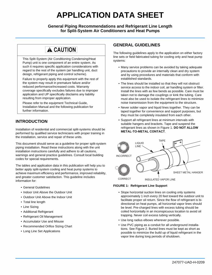
• Support all refrigerant lines at minimum intervals with
suitable hangers and brackets. Tape and suspend the
refrigerant lines as shown in Figure 1. DO NOT ALLOW
METAL-TO-METAL CONTACT.
FIGURE 1: Refrigerant Line Support
• Slope horizontal suction lines on cooling only systems
approximately 1 inch every 20 feet toward the outdoor unit to
facilitate proper oil return. Since the flow of refrigerant is bi-
directional on heat pumps, all horizontal vapor lines should
be level. Pre-charged lines with excess tubing should be
coiled horizontally in an inconspicuous location to avoid oil
trapping. Never coil excess tubing vertically.
• Use long radius elbows wherever possible.
• Use PVC piping as a conduit for all underground installa-
tions. See Figure 2. Buried lines must be kept as short as
possible to minimize the build up of liquid refrigerant in the
vapor line during long periods of shutdown.
This Split-System (Air Conditioning Condensing/Heat
Pump) unit is one component of an entire system. As
such it requires specific application considerations with
regard to the rest of the system (air handling unit, duct
design, refrigerant piping and control scheme).
Failure to properly apply this equipment with the rest of
the system may result in premature failure and/or
reduced performance/increased costs. Warranty
coverage specifically excludes failures due to improper
application and UP specifically disclaims any liability
resulting from improper application.
Please refer to the equipment Technical Guide,
Installation Manual and the following publication for
further information.
LIQUIDLINE
TAPE
INCORRECT
CORRECT INSULATED VAPOR LINE
SHEET METAL HANGER
General Piping Recommendations and Refrigerant Line Lengthfor Split-System Air Conditioners and Heat Pumps

247077-UAD-H-0209
2 Johnson Controls Unitary Products
FIGURE 2: Underground Application
• Pack fiberglass insulation and a sealing material such as
permagum around refrigerant lines where they penetrate
a wall to reduce vibration and to retain some flexibility. If
multiple line sets are routed through a common conduit,
then all lines must be insulated.
• Insulate all vapor lines with a minimum of 1/2 inch of foam
rubber. Liquid lines that will be exposed to direct sunlight
or high ambient temperatures such as an attic must also
be insulated.
The following additional guidelines apply to field fabricated
piping:
• Use hard drawn refrigeration type copper tubing where no
appreciable amount of bending around pipes or
obstructions is necessary. If soft copper must be used,
care should be taken to avoid sharp bends which may
cause a restriction.
• Braze all copper to copper joints with Silfos-5 or
equivalent brazing material. DO NOT USE SOFT
SOLDER.
• During brazing operations, flow an inert gas such as
nitrogen through the system to prevent internal scaling
and contamination.
TRAPS
Traps are not required if the piping is properly sized. Traps will
only add pressure drop to the system, further reducing capacity.
INDOOR UNIT ABOVE OUTDOOR UNIT
With this configuration, a common problem with the cooling
cycle (air conditioning or heat pump) is that the amount of liquid
sub-cooling varies as operating conditions change (such as
outdoor ambient). Under some conditions, it is possible that
flashing will actually occur in the liquid riser. As long as only
liquid is present in the liquid riser, the liquid static pressure loss
can be calculated at 1/2 psi per foot of rise. However, as soon
as flashing starts, the rate of pressure loss increases and
continues to increase as the amount of gas increases. For this
reason, the restrictions on elevation differences for this
configuration must be based on the entire range of operating
conditions.
When the indoor unit is above the outdoor unit, the pressure
loss in the liquid line during the cooling cycle will limit the
amount of elevation difference allowed. Since both friction and
static head contribute to pressure loss, it can be stated that the
elevation difference allowed decreases as the total equivalent
line length (horizontal plus vertical) increases.
OUTDOOR UNIT ABOVE INDOOR UNIT
COOLING CYCLE
When the outdoor unit is above the indoor unit, the static
pressure gain in the liquid line vertical drop (1/2 psi per foot)
may overcome the frictional pressure loss resulting in a total
pressure gain. A pressure gain in the liquid line is not
detrimental to the performance of the system.
On cooling only systems where the outdoor unit is located high
above the indoor coil, it may even be possible to reduce the
size of the liquid line. The static gain in the vertical drop will
offset the increased friction loss caused by smaller tubing. In
addition, the reduction in the total system charge due to the
smaller liquid line will enhance the reliability of the system.
With this configuration, gas velocity in the vapor riser must be
kept above 1000 feet per minute for proper oil return and below
3000 feet per minute to avoid noise and vibration problems.
HEATING CYCLE (Heat Pumps Only)
In the heating mode, liquid will travel from the indoor unit up the
liquid riser to the outdoor unit. This will result in a liquid line
pressure drop and a starved outdoor coil. Since heat pumps
have a defrost cycle, coil freeze-up is not a problem. However,
the resulting lower suction pressure will decrease the capacity
and efficiency of the system.
TOTAL LINE LENGTH
The total length of interconnecting tubing is the sum of all
horizontal and vertical runs from the indoor unit to the outdoor
unit. Total measured line lengths are limited to:
• The limiting factor on heat pumps is the storage capacity
of the accumulator. The limiting factor on cooling units is
oil sump capacity in the compressor.
• Total equivalent line lengths must only be used when
calculating pressure drop. Therefore use Table 1 to
calculate equivalent lengths for elbows.
TO INDOOR COILLIQUID LINE
PVCCONDUIT
INSULATEDVAPOR LINE
TO OUTDOOR UNIT
CAP(WATER TIGHT)

247077-UAD-H-0209
Johnson Controls Unitary Products 3
LINE SIZING
Every split-system unit is shipped with a factory-mounted sweat
fitting.
For split systems, interconnecting refrigerant lines should be
sized to match the factory supplied fittings unless the
application dictates different line sizes due to pressure drop,
refrigerant velocity constraints and/or line set lengths.
For cooling systems where the indoor and outdoor sections are
installed at the same elevation, refrigerant line sizes can usually
be matched with the factory supplied fittings. There are
exceptions for total line lengths exceeding 75 feet where
pressure drop limitations are exceeded. Refer to Long Line Set
section.
In some applications, especially where elevation differences
exist between the indoor and outdoor sections, suction and
liquid line sizes can be increased (or decreased) to minimize
pressure loss (or gain) and improve oil return to the
compressor. When sizing refrigerant lines for split-system
cooling units, the following factors must be considered:
1. Suction line pressure loss due to friction.
2. Suction line velocity for oil return.
3. Liquid line pressure loss due to friction.
4. Liquid line pressure loss (or gain) due to static head.
The effect that each of these factors have on a cooling system
depends on the orientation of the indoor and outdoor sections;
e.g., indoor unit above the outdoor unit. Before we discuss the
various orientations, it is important to understand a few things
about suction and liquid lines.
First, lets consider suction lines. Suction pressure loss reduces
system capacity by 1% for R-22 and 0.6% for R-410A per psi.
This can be a serious problem if suction lines are not sized
properly and pressure loss is 8 or 9 psi. Therefore, in order to
minimize capacity loss and maximize efficiency, suction
pressure loss must be minimized. This is achieved by
increasing the size of the suction line. As a good achievable
guideline, suction pressure loss should not be allowed to
exceed 3 psi (5 psi for R-410A).
Another important consideration when sizing suction lines is
refrigerant gas velocity in a suction riser. Velocity of at least
1000 feet per minute is required to carry oil up a suction riser.
Of course, this is only a factor when the outdoor unit is above
the indoor unit and the oil must overcome the pull of gravity to
return to the compressor. Greater refrigerant velocities are
obtained by decreasing the size of the suction line. In
applications where smaller tubing is required for a suction riser
and larger tubing is needed to minimize pressure drop, the riser
must be sized to achieve a velocity of at least 1000 feet per
minute while the horizontal runs can be sized larger to minimize
pressure drop.
NOTE: Must maintain 800 fpm minimum velocity on all
horizontal pipe runs.
Liquid lines must also be sized to minimize pressure change.
The total pressure change in a liquid line is the sum of the loss
due to friction and the loss (or gain) due to static head in the
vertical line. Liquid pressure loss reduces the amount of liquid
sub-cooling at a rate of 1 degree for every 3 psi for R-22 and 5
psi for R-410A. Sufficient sub-cooling must be maintained at the
expansion valve to provide proper operation. If the liquid
pressure drop is high enough to deplete all of the liquid sub-
cooling in the system, liquid will begin to flash reducing the
refrigerant flow through the indoor coil expansion valve.
However, as soon as flashing begins, the rate of pressure loss
increases and continues to increase as the amount of gas
increases. Careful consideration must be given to liquid line
sizing to minimize pressure drop and system charge. Liquid
lines should be sized as small as possible without exceeding
the recommended maximum pressure drop. The maximum
recommended liquid line velocity is 400 fpm. Velocities
exceeding 400 fpm can result in higher than acceptable noise
levels.
ADDITIONAL REFRIGERANT
In many applications, additional refrigerant will have to be
added to the system. The actual amount of charge that must be
added is determined by adding the following:
1. The indoor coil charge adjustment from the Installation
Manual.
2. The additional charge required for the interconnecting
piping and the size of the vapor and liquid lines.
Example: For a system using a 3/8 liquid line and a 3/4 suction
line with a total measured length of 50 feet,
NOTE: On residential equipment 15 feet of line is included on
nameplate charge.
TABLE 1: EQUIVALENT LENGTHS OF ELBOWS IN FEET
LINE SIZE
INCHES (O.D.)
90° SHORT
RADIUS
ELBOW (FT.)*
*. Two 45° radius ells equals one 90° radius ell.
90° LONG
RADIUS
ELBOW (FT.)
1/4 0.7 0.6
5/16 0.8 0.7
3/8 0.9 0.8
1/2 1.2 1.0
5/8 1.5 1.3
3/4 1.6 1.4
7/8 1.8 1.6
1-1/8 2.4 2.0
1-3/8 3.2 2.2
1-5/8 3.8 2.6
2-1/8 5.2 3.4
2-5/8 6.5 4.2
Liquid line 50 - 15 feet x 0.62 oz./foot = 21.7 oz.
Suction line 50 - 15 feet x 0.06 oz./foot = 2.1 oz.
Charge add for interconnecting tubing = 23.8 oz.

247077-UAD-H-0209
4 Johnson Controls Unitary Products
REFRIGERANT OIL MANAGEMENT
Inherent to all refrigeration systems is the presence of
refrigerant oil required for proper and continuous lubrication of
the compressor(s) bearings. All refrigeration systems, whether
they are packaged or split-systems circulate oil throughout the
system due to the miscibility of refrigerant oil. Split-systems,
due to their propensity for long piping lengths, can circulate
more refrigerant oil than packaged units, which can become a
problem if not recognized and managed. It is not unusual for a
given system to circulate as much as 15% of the original
compressor oil charge. Yet another side-effect of long piping
runs on split-systems is the aspect of system oil logging which
can occur even in the best of installations. Even the best piping
practices can inadvertently create oil traps in the system
especially when elevation differences between the indoor and
outdoor units occur. Refer to the section on Long Line Set
Applications for determining if refrigerant oil should be added
to the system.
ACCUMULATOR USE AND MISUSE
Ordinarily, suction line accumulators are not necessary on AC
units if the system is piped correctly and all of the precautionary
guidelines are followed. Refrigerant suction line accumulators
should only be installed on systems where liquid flood back to
the compressor(s) is highly likely. Accumulators are a standard
item on all heat pumps to avoid liquid flood back to the
compressor when switching from heat to cooling, reversal
before and after defrost and during low ambient heating
operation. If applied incorrectly suction line accumulators can
log oil or not provide the necessary liquid protection especially
when under sized.
The compressor suction line size should never be used as a
guideline for sizing the suction line accumulator. Matching the
accumulator piping size to the suction line size can often times
result in an undersized accumulator. Normally the accumulator
is sized for not less than 50% of the total system capacity.
Careful consideration must be given when attempting to apply
an accumulator to a split-system. On any given unit
approximately 80% of the system charge can be found between
the compressor and the expansion device during operation.
When the system shuts down the refrigerant is trapped
between the compressor check valve and the non-bleed
expansion device used on all York split-systems. During long
periods of shut down the refrigerant will migrate to the low side
of the system possibly accumulating in the evaporator coil and
horizontal suction lines.
If it has been determined that an accumulator must be installed
in the system proper positioning with respect to the compressor
suction line level is shown in Figure 3. It may become
necessary in many cases to elevate the outdoor unit to
accommodate proper piping and drainage back to the
accumulator during the off cycle. Multiple accumulators whether
piped in series or parallel are not recommended.
If an accumulator has been installed into a system and the
compressor experiences a burn out the accumulator must
be replaced. The debris from the burn out will clog the
orifice in the accumulator resulting in oil return starvation
to the replacement compressor.
FIGURE 3: Accumulator Field Piping
TABLE 2: LINE CHARGE
R-22 LINE CHARGE*
*. Charges are based upon 40°F suction temperature and
105°F liquid temperature.
SUCTION OZ./FT. LIQUID OZ./FT.
1/2 0.02 1/4 0.23
5/8 0.04 5/16 0.40
3/4 0.06 3/8 0.62
7/8 0.08 1/2 1.12
1-1/8 0.14 5/8 1.81
1-3/8 0.21 7/8 3.78
1-5/8 0.30 7/8 3.78
2-1/8 0.53 1-1/8 6.46
2-5/8 0.81 1-1/8 6.46
R-410A LINE CHARGE*
SUCTION OZ./FT. LIQUID OZ./FT.
1/2 0.04 1/4 0.19
5/8 0.06 5/16 0.33
3/4 0.09 3/8 0.51
7/8 0.12 1/2 1.01
1-1/8 0.20 5/8 1.64
1-3/8 0.31 3/4 2.46
1-5/8 0.43 7/8 3.27
2-1/8 0.76 1-1/8 5.58
2-5/8 1.17
Accumulator
Liquid Level
Drainage in Off Cycle
ScrollCompressor

247077-UAD-H-0209
Johnson Controls Unitary Products 5
RECOMMENDED ORIFICE SIZE
ORIFICE SIZING
Use the York® Comfort Cooling Piping software to determine
liquid line pressure drop to select proper orifice sizing.
LONG LINE SET APPLICATIONS
This section is intended for long line applications that exceed
75'. When sizing line sets under 75', always use factory
supplied connections. If your application is outside of the
selection charts, your application must be approved through the
Application Engineering group.
LIQUID LINE SIZING CRITERIA
The following considerations have already been accounted for
when relating to the selection charts.
• R-22 Maximum Pressure Drop is 35 psig
• R-410A Maximum Pressure Drop is 60 psig
• Increased charge levels
• Maximum recommended velocity of 400 fpm
• Minimum velocity of 100 fpm
Liquid Line Selection Chart: The charts below show the line
sizes that can be selected for each tonnage of unit and the
maximum equivalent length and maximum rise of the line. The maximum actual line length is 200 feet. Equivalent line lengths would include elbows and other components that would increase the equivalent length.
Shaded area indicates system needs oil added (Refer to Oil
Addition section on page 7).
TABLE 3: RECOMMENDED ORIFICE SIZE
LIQUID LINE PRESSURE
GAINS (PSI)
STANDARD
ORIFICE
SIZE
LIQUID LINE
PRESSURE
LOSSES (PSI)
51 41 31 21 11 11 21
Thru Thru Thru Thru Thru Thru Thru
60 50 40 30 20 20 30
CORRECTED
ORIFICE SIZE
CORRECT ORIFICE
SIZE
- - - - 39 41 43 45
- - - 39 41 43 45 47
41 43 45 47 49 51 53 55
43 45 47 49 51 53 55 57
45 47 49 51 53 55 57 59
47 49 51 53 55 57 59 61
49 51 53 55 57 59 61 63
51 53 55 57 59 61 63 65
53 55 57 59 61 63 65 67
55 57 59 61 63 65 67 69
57 59 61 63 65 67 69 71
59 61 63 65 67 69 71 73
61 63 65 67 69 71 73 75
63 65 67 69 71 73 75 78
65 67 69 71 73 75 78 81
69 71 73 75 75 78 81 84
71 73 75 78 78 81 84 87
75 75 78 81 81 84 87 90
78 78 81 84 84 87 90 93
81 81 84 87 87 90 93 96
84 84 87 90 90 93 96 99
87 87 90 93 93 96 99 102
90 90 93 96 96 99 102 105
93 93 96 99 99 102 105 105
TABLE 4: R22 LIQUID LINE, MAXIMUM RISE CHART
Tons Line
Size
Maximum Total Equivalent Length Velocity
75 100 125 150 175 200 225 250 FPM
1.5 5/16 60 55 50 50 45 40 35 30 186
3/8 65 65 65 60 60 60 55 55 115
2.0 5/16 50 45 35 30 25 20 15 5 248
3/8 60 60 60 55 55 50 45 45 154
2.5 3/8 60 55 55 50 45 40 35 35 192
1/2 65 65 65 65 65 60 60 60 103
3.0 3/8 55 50 45 40 35 30 25 20 231
1/2 65 65 65 65 60 60 60 55 124
3.5 3/8 50 45 35 30 25 20 10 5 269
1/2 65 65 60 60 60 55 55 55 145
4.0 3/8 45 35 30 20 15 10 - - 308
1/2 65 60 60 60 55 55 50 50 165
5.0 3/8 30 20 10 - - - - - 385
1/2 60 60 55 50 50 45 45 40 207
7.5 1/2 50 45 40 35 30 25 15 10 310
5/8 65 60 60 60 55 55 55 50 193
10 5/8 60 55 55 50 50 45 40 40 257
3/4 65 65 65 60 60 60 55 55 175
12.5 5/8 55 50 45 40 35 30 25 25 322
3/4 65 60 60 55 55 55 50 50 219
15 3/4 60 60 55 55 50 50 45 45 263
7/8 65 65 65 60 60 60 60 55 186
20 3/4 55 50 45 45 40 35 30 25 351
7/8 65 60 60 55 55 55 50 50 248
25 7/8 60 55 55 50 50 45 40 40 310
1-1/8 65 65 65 65 65 60 60 60 182

247077-UAD-H-0209
6 Johnson Controls Unitary Products
*Note: Exceeds recommended maximum velocity of 400 fpm,
consider noise when selecting this pipe size.
Example: 3 Ton cooling unit with 175' of equivalent length,
condensing unit is below the evaporator with 80' of vertical rise
to the evaporator.
Answer: You should have selected 1/2”. Why did you select
this size? Because at 175' equivalent length with a 3 ton
system, the maximum rise is 75’ for 3/8” and 95’ for 1/2".
Multi Stage Refrigeration Systems: When sizing the liquid
line for a system with either a 2 stage scroll compressor
(residential) or when a single refrigeration system utilizes
compressor staging for capacity reduction (commercial).
ALWAYS calculate the liquid line size with the maximum
tonnage rating of the unit.
SUCTION LINE SIZING CRITERIA
The following considerations have already been accounted for
when relating to the selection charts.
• Minimum velocity of 1000 fpm for vertical lines and 800
fpm for horizontal lines guarantee proper oil return
• Minimal pressure drop to minimize capacity loss
Suction Line Selection Chart: The charts below show the line
sizes that can be selected for each tonnage of unit and the
percent of capacity reduction the system will have because of
the long line set application. The maximum actual line length is 200 feet, equivalent line lengths would include elbows and other components that would increase the equivalent length.
Note: (-) Indicates unacceptable pressure drop in suction line
TABLE 5: R-410A LIQUID LINE, MAXIMUM RISE CHART
Tons Line
Size
Maximum Total Equivalent Length Velocity
75 100 125 150 175 200 225 250 FPM
1.5 5/16 75 90 85 85 80 75 75 70 223
3/8 75 100 95 95 95 95 90 90 138
2.0 5/16 75 80 75 70 65 60 55 50 297
3/8 75 95 90 90 85 85 85 80 184
2.5 3/8 75 90 85 85 80 80 75 70 230
1/2 75 100 100 100 100 95 95 95 123
3.0 3/8 75 85 85 80 75 70 65 60 276
1/2 75 100 100 95 95 95 90 90 148
3.5 3/8 75 80 75 70 65 60 55 50 322
1/2 75 95 95 95 95 90 90 90 173
4.0 3/8 75 75 70 60 55 45 40 35 368
1/2 75 95 95 95 90 90 90 85 198
5.0 3/8 70 60 50 40 30 20 10 0 *460
1/2 75 95 90 90 85 85 80 80 247
7.5 1/2 75 80 80 75 70 65 60 55 370
5/8 75 95 95 95 90 90 90 85 231
10 5/8 75 90 90 85 85 80 80 75 307
3/4 75 100 95 95 95 95 90 90 210
12.5 5/8 75 85 85 80 75 70 65 65 384
3/4 75 95 95 90 90 90 90 85 262
15 3/4 75 95 90 90 85 85 85 80 315
7/8 75 100 95 95 95 95 95 90 222
20 3/4 75 85 85 80 75 70 70 65 419
7/8 75 95 95 90 90 90 85 85 296
25 7/8 75 95 90 90 85 85 80 75 371
1-1/8 75 100 100 100 95 95 95 95 217
TABLE 6: R22 SUCTION LINE, CAPACITY REDUCTION
CHART (%)
Tons Line
Size
Total Equivalent Length Velocity
75 100 125 150 175 200 225 250 FPM
1.5 5/8 5 7 9 12 - - - - 1682
3/4 4 5 6 7 9 11 12 13 1147
2.0 3/4 3 4 6 8 9 11 - - 1529
7/8 3 4 5 6 7 8 9 10 1081
2.5 3/4 3 5 7 - - - - - 1911
7/8 2 3 4 5 7 8 9 10 1351
3.0 3/4 5 7 8 - - - - - 2294
7/8 2 3 5 6 8 9 10 11 1621
3.5 7/8 2 4 6 7 - - - - 1892
1-1/8 2 3 4 4 5 5 6 7 1109
4.0 7/8 3 5 7 - - - - - 2162
1-1/8 2 2 3 4 4 5 6 7 1268
5.0
7/8 5 - - - - - - - 2703
1-1/8 1 2 3 4 5 6 6 7 1585
1-3/8 1 2 3 3 4 4 5 6 1048
7.51-3/8 1 2 2 2 3 4 5 5 1561
1-5/8 1 2 2 2 3 3 4 4 1103
101-3/8 1 1 2 3 4 5 6 - 2082
1-5/8 1 1 2 2 2 3 3 3 1471
12.51-5/8 1 1 1 2 2 3 3 4 1839
2-1/8 1 1 1 1 2 2 3 3 1057
151-5/8 1 1 2 3 3 4 4 5 2207
2-1/8 1 1 1 2 2 2 2 3 1268
202-1/8 1 1 1 1 2 2 2 2 1691
2-5/8 1 1 1 1 1 2 2 2 1096
252-1/8 1 1 1 1 1 2 2 3 2114
2-5/8 1 1 1 1 1 2 2 2 1370
247077-UAD-H-0209
Johnson Controls Unitary Products 7
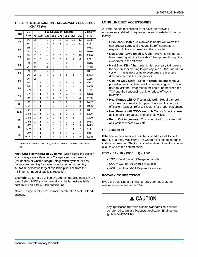
*Velocity is below 1000 fpm, should only be used on horizontal
line.
Multi Stage Refrigeration Systems: When sizing the suction
line for a system with either a 2 stage scroll compressor
(residential) or when a single refrigeration system utilizes
compressor staging for capacity reduction (commercial).
ALWAYS select the largest available pipe size from the
minimum tonnage of capacity reduction.
Example: 10 ton R-22 2 pipe system that reduces capacity to 5
tons. Select 1-3/8” suction line, this is the largest available
suction line size for a 5 ton suction line.
Note: 2 stage scroll compressors operate at 67% of full load
capacity.
LONG LINE SET ACCESSORIES
All long line set applications must have the following
accessories installed if they are not already installed from the
factory.
• Crankcase Heater - A crankcase heater will warm the
compressor sump and prevent the refrigerant from
migrating to the compressor in the off cycle.
• Non Bleed TXV's on all ID Coils - Prevents refrigerant
from bleeding into the low side of the system through the
evaporator in the off cycle.
• Hard Start Kit - A hard start kit is necessary to increase
the compressor starting torque anytime a TXV is used in a
system. This is necessary to overcome the pressure
difference across the compressor.
• Cooling Only Units - Require liquid line check valve
placed in the liquid line near the condensing unit. This is
used to lock the refrigerant in the liquid line between the
TXV and the condensing unit to reduce off cycle
migration.
• Heat Pumps with Orifice in OD Coil - Require check
valve and solenoid valve placed in liquid line to prevent
off cycle migration, refer to Figure 4 for proper placement.
• Heat Pumps with TXV’s on both Coils - Do not require
additional check valves and solenoid valves.
• Pump Out Accessory - This is required on commercial
applications where available.
OIL ADDITION
If the line set you selected is in the shaded area of Table 4,
(R22 Liquid Line, Maximum Rise Chart) oil needs to be added
to the compressors. The formula below determines the amount
of oil to add to the compressors.
(TSC x .03 x 16) - (SOC x .1) = AOR
• TSC = Total System Charge in pounds
• SOC = System Oil Charge in ounces
• AOR = Additional Oil Required in ounces
ROTARY COMPRESSOR
If you are selecting a unit with a rotary compressor, the
maximum actual line set is 100 ft.
TABLE 7: R-410A SUCTION LINE, CAPACITY REDUCTION
CHART (%)
Tons Line
Size
Total Equivalent Length Velocity
75 100 125 150 175 200 225 250 FPM
1.5 5/8 3 4 5 7 8 10 12 13 1185
3/4 3 4 5 6 8 10 11 12 808*
2.0 5/8 2 4 6 7 - - - - 1582
3/4 3 4 4 5 6 7 8 10 1078
2.5 3/4 2 3 4 5 6 7 8 10 1346
7/8 2 3 4 5 6 6 7 8 952*
3.0 3/4 2 2 4 5 6 8 - - 1616
7/8 2 3 3 4 5 5 6 7 1143
3.5 3/4 2 3 4 6 - - - - 1887
7/8 2 2 3 3 4 5 6 7 1333
4.0 3/4 2 4 5 - - - - - 2155
7/8 1 2 2 3 5 6 7 8 1523
5.0 7/8 1 2 3 5 6 - - - 1905
1-1/8 1 2 2 3 3 4 4 5 1117
7.51-1/8 1 1 2 2 3 4 5 5 1676
1-3/8 1 1 2 2 3 3 3 4 1100
101-3/8 1 1 1 2 2 2 3 3 1467
1-5/8 1 1 1 2 2 2 3 3 1036
12.51-3/8 1 1 1 1 2 2 3 4 1834
1-5/8 1 1 1 1 2 2 2 3 1295
151-3/8 1 1 1 2 3 4 5 - 2200
1-5/8 1 1 1 1 1 2 2 2 1554
201-5/8 1 1 1 1 1 2 3 3 2073
2-1/8 1 1 1 1 1 1 2 2 1191
251-5/8 1 1 1 2 3 4 - - 2591
2-1/8 1 1 1 1 1 1 1 2 1489
Any application that falls outside standard limits should
be referred to Unitary Products application Engineering
@ 1-877-UPG-SERV.

Subject to change without notice. Printed in U.S.A. 247077-UAD-H-0209Copyright © 2009 by Johnson Controls, Inc. All rights reserved. Supersedes: 247077-UAD-G-1008
Johnson Controls Unitary Products
5005 York Drive
Norman, OK 73069
FIGURE 4: Heat Pump Solenoid/Check Valve Installation
Arrangement
TABLE 8: CRANKCASE HEATERS FOR SPLIT UNITS
Model Part # Voltage WattsMin.
Circum
Max.
Circum
Danfoss Scrolls
(All)
S1-02541100000 240 70 19.625 27.125
S1-02541101000 460 70 19.625 27.125
S1-02541102000 575 70 19.625 27.125
Copeland Scrolls
(Residential)
S1-02531959000 240 80 22 26
S1-02531960000 460 80 22 26
S1-02531958000 575 80 22 26
Copeland Scrolls
(Commercial)S1-02533474240 240 90 28.75 35.75
Bristol H23AS1-02533474460 460 90 28.75 35.75
S1-02533474575 575 90 28.75 35.75
Bristol Recips
(Remainder)
S1-02537399240 240 70 21.81 29
S1-02537399480 460 70 21.81 29
S1-02537399575 575 70 21.81 29
TABLE 9: HP SOLENOID VALVE
Model Part# Voltage
3/8" Liquid Line Solenoid Valve S1-02541203000 24V
TABLE 10: MAGNETIC CHECK VALVES
Pipe Diameter Part #
3/8” S1-02222498000
1/2” S1-02211519000
5/8” S1-02209099000
3/4” S1-02211520000
7/8” S1-02211481000
1-1/8” S1-02211521000
Any application that falls outside standard limits should
be referred to Unitary Products application Engineering
@ 1-877-UPG-SERV.