1 applications/ mohr’s circle. 2 uniaxial stress is given by: special forms of the stress tensor...
TRANSCRIPT
1
APPLICATIONS/MOHR’S CIRCLE

2
• Uniaxial stress is given by:
000
000
00
Special Forms of the Stress Tensor
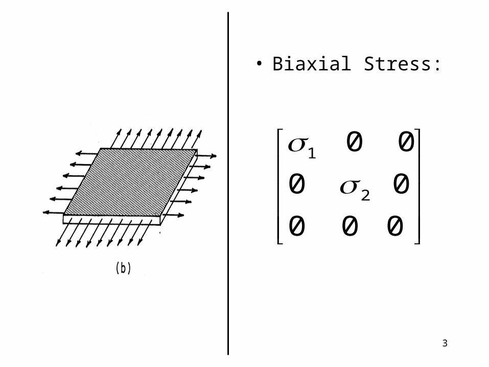
Fig. 1. Examples of special state of
stress: (a) Uniaxial; (b) biaxial; (c)
hydrostatic; (d) pure shear
3
• Biaxial Stress:
0 0 0
00
00
2
1

4
• Hydrostatic Pressure:
• It is a occurs in liquids; it is a special case of triaxial stress, when the three principal stresses are equal.
p
p
p
00
00
00

5
• Pure Stress:
• It is a special case of biaxial stress, as will be seen by performing a 45o rotation.
• Students are required to show that the above statement is correct.
000
00
00
6
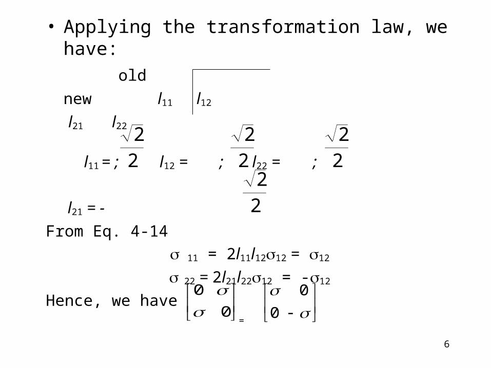
• Applying the transformation law, we have:
old
new l11 l12
l21 l22
l11 = ; l12 = ; l22 = ;
l21 = -
From Eq. 4-14
11 = 2l11l1212 = 12
22 = 2l21l2212 = -12
Hence, we have=
22
22
22
22
0
0
0
0

7
• Fig. 2. A state of pure shear stress and strain in an isotropic material.

8
Important Stresses in Plasticity
• It is often useful to decompose ij into two components:
'''ijijijij
Deviatoric, or Deviator,or Shear stress Tensor
Spherical, or Hydrostatic,or Dilatational stress Tensor
)(
)(
)(
111212
231112
131211
m
m
m
m
m
m
00
00
00
(4-33)
[Responsible for Failure] [Does Not cause Deformation]

9
• It can be found that m has to be equal to:
• The deviatoric (or shear) components of stress are responsible for failure (under shear) or distortion.
• The hydrostatic (or spherical) stress produces volume change and does not cause any plastic deformation. This explains why shrimp can live in great ocean depths without problems.
• The above stress components are often used in plasticity.
331332211 I
m (4-34)

10
• Consider a shrimp under two conditions:(a) depth of 100 m, with hydrostatic pressure of 1.0 MPa
acting on it, and
(b) squeezed between our fingers, with an applied stress (uniaxial) of about 0.5 MPa.
– While the Hydrostatic pressure will not bother the shrimp, it will certainly crush under the applied tensile stress.
– The difference between the two cases is the deviatoric stress, which is 0 and 0.25 MPa for cases (a) and (b) respectively.

11
2-D TRANSFORMATION
• Recall the three equations obtained for the 2-D transformation of stress:
2sin2cos22
' xyyxyx
x
2sin2cos22
' xyyxyx
y
2cos2sin2
'' xyyx
yx
(4-35a)
(4-35c)
(4-35b)

12
• ***As in all Transformation cases, Eqs. 4-35 give the variation of and with direction in the material***.
• The direction being specified by the angle relative to the originally chosen x-y coordinate system.
• Taking the derivative d/d of Eq. 4-35(a) and equating the result to zero gives the coordinate axes rotations for the maximum and minimum values of .
• Two angles n separated by 90o satisfies Eq. 3-36
yx
xyn
22tan
(4-36)

13
• The corresponding maximum and minimum normal stresses from Eq. 4-35, called the principal normal stresses can be obtained by substituting 4-36 into 4-35, and is given as:
• Note that the shear stress at the n orientation is found to be zero.
• Conversely, if the shear stress is zero, then the normal stresses are the principal normal stresses
2
2
21 22, xy
yxyx
(4-37)

14
• Similarly, Eq. 4-35c and d/d = 0 gives the coordinate axes rotation for the maximum shear stress.
• The corresponding shear stress from Eq. 4-35c is
• This is the maximum shear stress in the x-y plane and is called the principal shear stress.
xy
yxs
22tan
(4-38)
2
2
max 2 xyyx
(4-39)

15
max can be expressed in terms of the principal normal stresses 1 and 2 by substituting Eq. 4-39 into 4-37 to obtain
• The absolute value is necessary for max due to the two roots in Eq. 4-39
221
max
(4-40)

16
Example
• At a point of interest on the free surface of an engineering component, the stresses with respect to a convenient coordinate system in the plane of the surface are x = 95, y = 25, xy = 20 MPa. Determine the principal stresses and the orientations of the principal planes.

17
Solution (A)• Substitution of the given values into Eq. 4-36 gives the
angle to the coordinate axes of the principal normal stresses.
n = 14.9o (CCW)
Substituting into Eq. 4-37 gives the principal normal stresses
1, 2 = 60 40.3 = 100.3, 19.7 MPa
742
2tan
yx
xyn
22
21 )2
(2
, xyyxyx

18
• Alternatively, a more rigorous procedure is to use = n = 14.9 in Eq. 4-35a, which gives
= x’ = 1 = 100.3 MPa
• Use of = n + 90o = 104.9o in Eq. 4-35a then gives the normal stress in the other orthogonal direction.
= y’ = 2 = 19.7 MPa
The zero value of at = n can also be verified by using Eq. 4-35c.
Solution (B)

19
• A convenient graphical representation of the transformation equations for plane stress.
• On versus coordinates, these equations can be shown to represent a circle, called Mohr’s circle.
• The Development is as follows:– Isolate all terms of Eq. 4-35a containing on one side.
– Then square both sides of 4-35a and 4-35c and sum.
– Invoke simple trigonometric identities to eliminate , and we obtain
Mohr’s Circle
22
22
22 xyyxyx
(4-41)

20
• This equation is of the form:
which is the equation of a circle on a plot of versus with center at the coordinates (a, b) and radius r, where
Comparison with Eq. 4-37 and 4-39, revealed that the maximum and minimum normal stresses can be written as:
222 rba (4-42)
2
2
2,0,
2 xyyxyx rba
(4-43)
max21 2,
yxra (4-44)

21
• Confusion concerning the signs in Mohr’s circle can be resolved as follws:– For shear, the portion that causes clockwise rotation is
considered positive, and the portion that causes counter-clockwise rotation is considered negative
– For normal stresses, tension is positive, and compression is negative.
• Graduate students are required to read up the 3-D Mohr’s circle.

22
• Repeat the previous problem using Mohr’s circle method. Recall that the original state of stress is
x = 95, y = 25, and xy = 20 MPa
Problem
23
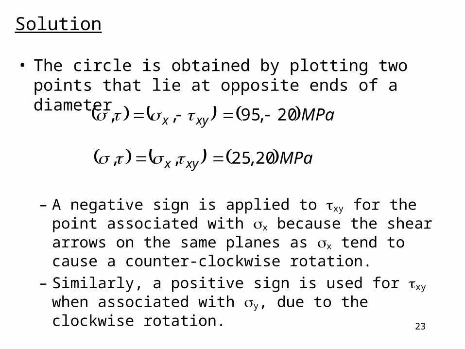
• The circle is obtained by plotting two points that lie at opposite ends of a diameter
– A negative sign is applied to xy for the point associated with x because the shear arrows on the same planes as x tend to cause a counter-clockwise rotation.
– Similarly, a positive sign is used for xy when associated with y, due to the clockwise rotation.
Solution
MPaxyx 20,95,,
MPaxyx 20,25,,

24
• Recall Eq. 4-43
• The center of the circle is (a, b), which lies on the axis:
• The hypotenuse of the triangle/ radius of the circle is also the principal shear stress, which is given as:
MPayxctr 0,600,
2, .
2
2
2,0,
2 xyyxyx rba
MPar xyyx 3.402035
2222
2
max

25
• The angle with the - axis is
• A counter-clockwise rotation of the diameter of the circle by this 2n gives the horizontal diameter that corresponds to the principal normal stress.
• Their values are obtained from Eq. 4-44:
1, 2 = 100.3 and 19.7 MPa
)(74.292
3520
2tan
CCWon
n
max21 2,
yxra

26
(95, -20)
(60, 40.3)
(19.7, 0)(100.3, 0)
(25, 20)
60, MPa
, MPa2n
Mohr’s circle corresponding to the state of stress (60, -40.3)