0751p victaulic in mechanical piping - natspec · is applicable to victaulic piping, ... the pump...
TRANSCRIPT
07 MECHANICAL 0751p VICTAULIC in mechanical piping
© NATSPEC (Apr 18) 1 "[Insert date]"
0751P VICTAULIC IN MECHANICAL PIPING
Branded worksection This branded worksection Template has been developed by NATSPEC in conjunction with VICTAULIC and may be used whilst the Product Partner is licensed to distribute it. The copyright remains with NATSPEC. As with all NATSPEC worksections, it is the responsibility of the user to make sure it is completed appropriately for the project. The user should also review its applicability for local conditions and regulations. Check www.natspec.com.au for the latest updated version.
Worksection abstract This branded worksection Template is applicable to VICTAULIC piping, valves, fittings and accessories commonly used for mechanical systems including chilled, condenser and heating water, steam, condensate, and liquid fuels. It covers piping in a variety of materials including steel, copper and plastic, and includes valves, fittings, supports, and accessories. The worksection is based on AS 4041. The worksection also covers strainers and isolating, non-return, throttling, level control, pressure relief, air relief, and pressure reducing valves. It does not include thermostatic, solenoid, motorised modulating, or refrigerant valves.
Background VICTAULIC products applicable to this worksection include couplings, fittings, valves, accessories and tools as outlined in VICTAULIC General Catalogue and internet website www.victaulic.com.
Guidance text All text within these boxes is provided as guidance for developing this worksection and should not form part of the final specification. This Guidance text may be hidden or deleted from the document using the NATSPEC Toolbar or the hidden text Hide and Delete functions of your word processing system. For additional information visit FAQs at www.natspec.com.au.
Optional style text Text in this font (blue with a grey background) covers items specified less frequently. It is provided for incorporation into Normal style text where it is applicable to a project.
Related material located elsewhere in NATSPEC Related material may be found in other worksections. See for example:
• 0721 Packaged air conditioning also includes some refrigeration piping applicable to split systems.
• 0755 Medical gas systems
• 0748 Chilled beams.
• 0812 Tapware includes thermostatic mixing valves and plumbing tapware.
• 0815 Boiling, chilled and filtered water dispensers.
• 0823 Cold and heated watercovers potable water.
• 0824 Fuel gas includes natural, LPG and similar fuel gases (but not laboratory or industrial type gases like acetylene).
Material not provided by VICTAULIC This branded worksection includes generic material which may not be provided by the Product Partner including:
• ABS piping systems.
• PVC piping systems.
• Some valve types such as calibrated balancing valves.
• Automatic air vents.
• Vacuum breakers.
• Some steam and condensate components e.g. steam traps and steam separators.
• Hot water panel radiators.
• Pressure gauges and thermometers.
• Flow sensors.
• Pipe support systems.
Documenting this and related work You may document this and related work as follows:
• Refer to AIRAH DA16 for water piping.
• General plant access requirements are included in ACCESS FOR MAINTENANCE in the 0171 General requirements worksection. Make sure suitable plant access details for special or critical situations are included in the drawings.
• It is preferable to include piping schematics that show valving, demountable joints etc.

07 MECHANICAL 0751p VICTAULIC in mechanical piping
© NATSPEC (Apr 18) 2 "[Insert date]"
• This worksection contains text, including Optional style text, which may be changed to Normal style text for use in design and construct projects. See NATSPEC TECHreport TR 03 for information on specifying Design and Construct for mechanical services.
• The Normal style text of this worksection may refer to items as being documented elsewhere in the contract documentation. Make sure they are documented.
Specifying ESD The following may be specified by retaining default text:
• Piping materials alternative to traditional materials (e.g. copper, steel).
• Measures relating to commissioning to improve performance and reduce mechanical systems energy consumption.
• Durable components, particularly for corrosion resistance.
Refer to the NATSPEC TECHreport TR 01 on specifying ESD.
1 GENERAL
VICTAULIC is a worldwide leader in mechanical piping solutions. Since pioneering grooved end technology for mechanical pipe joining in 1925, VICTAULIC has been providing customers the world over with innovative, reliable piping systems solutions for multiple applications and markets.
1.1 RESPONSIBILITIES General Requirement: Provide VICTAULIC mechanical piping systems, as documented. Documented is defined in 0171 General requirements as meaning contained in the contract documents.
1.2 DESIGN Design pressures Design temperatures may also be a factor.
Design pressures: To AS 4041 but not less than the maximum hydrostatic head at the location, given the pump shut off head for the maximum impeller size for the pump casing. Piping system Requirement: Provide mechanical piping systems complete with all necessary piping, valves, supports, guides, drains, vents, expansion compensation and all fittings necessary for their safe and efficient operation. The Optional style text in this clause may be changed to Normal style text when the contractor is to design and select the mechanical piping systems. Use 0701 Mechanical systems to describe design parameters for mechanical systems, as a whole.
Design: Design mechanical piping systems, as documented.
Selection parameters included in the SELECTIONS schedules should not be repeated here. The schedules’ Guidance text includes suggestions for modification to suit design and construct projects.
Use the Piping schedule to define the piping systems required.
Piping design, application and calculations Standards: Conform to the recommendations of one or more of the following: - AIRAH Design Application Manuals. - ASHRAE Handbooks. - CIBSE Guides. Methods of calculation: Manual or software that employs the data and methods in the applicable standard. Valves and pipeline components for water systems Complete to suit the project. The valve types are included in the respective Water valve table.
Requirement: Provide the following valves and pipeline components: - Isolating valves: On both sides of each component requiring isolation including coils, pumps, heat
exchangers, tanks chillers and boilers and at the following locations:
List locations e.g. at branches to plant rooms, branches to floors.
- Non-return valves: On the discharge of pumps operating in parallel and in other locations required for safe and proper system operation.

07 MECHANICAL 0751p VICTAULIC in mechanical piping
© NATSPEC (Apr 18) 3 "[Insert date]"
List other locations to suit the project.
- Throttling and balancing valves: On the discharge of pumps, at each coil and other item of heat transfer equipment and in other locations required for safe and proper system operation.
List other locations to suit the project.
- Check valves: On the discharge of pumps operating in parallel and at other locations required for the safe and efficient operation of the system.
List other locations to suit the project.
- Strainers: On the suction side of pumps, before each automatic control valve and in other locations required for safe and proper system operation.
List other locations to suit the project.
- Level control valves: On the makeup water to cooling tower basins and tanks.
List locations.
- Pressure-reducing valves: [complete/delete]
List locations.
- Pressure relief valves: To statutory requirements. - Vacuum breaker valves: [complete/delete]
List locations.
- Venting provisions: Conform to DRAINS, VENTS AND GRADING. - Drains and drain valves: Conform to DRAINS, VENTS AND GRADING. - Dial thermometers: [complete/delete]
List locations.
- Pressure gauges: [complete/delete]
List locations.
- Water flow measurement: [complete/delete]
List locations and type of device required (e.g. pitot type sensor or flow meter).
- Gauge valves: On each pressure gauge and at each point with provision for connecting a pressure gauge. - Thermometer wells: Conform to INSTRUMENTS – GENERAL. - Pressure tappings: Conform to INSTRUMENTS – GENERAL. - Test plugs: Conform to INSTRUMENTS – GENERAL. - Hot water panel radiator valves: Conform to HOT WATER PANEL RADIATORS. Valves and pipeline components for steam and condensate systems Complete to suit the project. Valves and pipeline components for water systems may be used as a guide.
Requirement: Provide the following valves and pipeline components: - [complete/delete]
Provide a list similar to that for water systems above.
Valves and pipeline components for liquid fuel systems Complete to suit the project. Valves and pipeline components for water systems may be used as a guide.
Requirement: Provide the following valves and pipeline components: - Automatic air vents: [complete/delete] - Automatic control valves: Where required for the correct operation of steam using equipment. - Ball float valves: [complete/delete] - Combined sight glass and non-return valve: [complete/delete] - High domestic hot water temperature cutout: [complete/delete] - Isolating valves: [complete/delete] - Non-return valves: [complete/delete]

07 MECHANICAL 0751p VICTAULIC in mechanical piping
© NATSPEC (Apr 18) 4 "[Insert date]"
- Pressure reducing valve sets: [complete/delete] - Pressure relief valves: [complete/delete] - Safety valves: [complete/delete] - Steam humidifiers: [complete/delete] - Steam operated condensate pumps: [complete/delete] - Steam separators: [complete/delete] - Steam traps: [complete/delete] - Strainers: [complete/delete] - Strainers: [complete/delete] - Vacuum breaker valves: [complete/delete] - [complete/delete]
1.3 COMPANY CONTACTS VICTAULIC technical contacts Website: www.victaulic.com
1.4 CROSS REFERENCES General Requirement: Conform to the following: - 0171 General requirements. 0171 General requirements contains umbrella requirements for all building and services worksections.
List the worksections cross referenced by this worksection. 0171 General requirements references the 018 Common requirements subgroup of worksections. It is not necessary to repeat them here. However, you may also wish to direct the contractor to other worksections where there may be work that is closely associated with this work.
NATSPEC uses generic worksection titles, whether or not there are branded equivalents. If you use a branded worksection, change the cross reference here.
- 0701 Mechanical systems. 0701 Mechanical systems deals with matters common to more than one Mechanical worksection.
- 0753 Water treatment. - 0771 Automatic controls.
1.5 STANDARD General Standard: To AS 4041.
1.6 MANUFACTURERS DOCUMENTS Technical manuals General: VICTAULIC documents relating to this worksection are: - VICTAULIC G-103 General Catalogue inclusive of supplementary submittals. - VICTAULIC I-100 Field Installation Handbook. - VICTAULIC I-P500 Vic-Press Field Installation Handbook. - VICTAULIC I-600 Copper Field Installation Handbook. - VICTAULIC I-900 Field Installation Handbook.
1.7 INTERPRETATION Abbreviations General: For the purposes of this worksection the following abbreviations apply: - ABS: Acrylonitrile butadiene styrene. - EPDM: Ethylene propylene diene monomer. - PTFE: Polytetrafluoroethylene. - HDPE: High density polyethylene.

07 MECHANICAL 0751p VICTAULIC in mechanical piping
© NATSPEC (Apr 18) 5 "[Insert date]"
Edit the Abbreviations subclause to suit the project or delete, if not required. List alphabetically.
Definitions General: For the purposes of this worksection the following definitions apply: - Accuracy: The closeness of the agreement between the result of a measurement and the true value
of the particular quantity being measured. - Error: The measured value minus the true value of the particular quantity being measured. - Resolution: The smallest difference between indications of a displaying device that can be
meaningfully distinguished. - Closed system: A water distribution or circulation system in which the water does not come into
contact with air during circulation and to which, in normal operation, no water is added. - Open system: A water distribution or circulation system that is not a closed system. The above definitions are based on AS 3807 which in turn is derived from an ISO document. AS 3807 cautions that the term precision should not be used for accuracy. Resolution is also sometimes referred to as precision.
For a digital displaying device, resolution is the change in the indication when the least significant digit changes by one step. For analog devices resolution is usually the scale smallest division.
The distinction between accuracy and resolution is important. A digital thermometer may have a resolution of 0.1 K but an accuracy of only 1.0 K at the particular temperature, because of calibration drift, measurement method or for other reasons.
See also the 0171 General requirements worksection for the definition of tolerance.Edit the Definitions subclause to suit the project or delete, if not required. List alphabetically.
1.8 SUBMISSIONS
Samples e.g. of valves or instruments, may be required but can be costly unless incorporated into the works.
Certification VICTAULIC requirements: Submit evidence that a VICTAULIC certified trainer has visited the site, reviewed the installation and certified that the installation meets the manufacturer’s requirements. Subcontractors Installers training: Submit evidence that persons installing VICTAULIC mechanical piping systems have received training from a VICTAULIC certified trainer. Products and materials State if certificates are required regarding valves or instruments and their compliance with specified standards, design pressures etc.
Calibrated balancing valves: For each type and size of valve, submit a manufacturer’s calibration chart relating pressure drop to fluid flow across the valve opening range. Submit independent test reports giving accuracy and repeatability tolerances. Automatic/dynamic system balancing valves: For each type and size of valve, submit a manufacturer’s report verifying a flow rate control accuracy of ± 5% or better is maintained over the selected pressure differential control range. Tests 0171 General requirements covers tests in Definitions and calls for an inspection and testing plan under SUBMISSIONS, Tests.
Hydrostatic testing: Submit test results of completed installation. Detail the tests required in PRODUCTS or EXECUTION, as appropriate, and list the submissions required here.
1.9 INSPECTION Notice VICTAULIC inspections: Give notice so inspection may be made by a VICTAULIC certified trainer of the following: - Installation at commencement, 50% installed and on completion. - Grooving tool training and coupling installation training before work commences. Amend to suit the project, adding critical stage inspections required. Hold points, if required, should be inserted here.

07 MECHANICAL 0751p VICTAULIC in mechanical piping
© NATSPEC (Apr 18) 6 "[Insert date]"
2 PRODUCTS
2.1 GENERAL Product substitution Other products: Conform to PRODUCTS, GENERAL, Substitutions in 0171 General requirements. The 0171 General requirements clause sets out the submissions required if the contractor proposes alternative products. Refer also to NATSPEC TECHnote GEN 006 for more information on proprietary specification.
Storage and handling Requirement: For extended storage, keep out of direct sunlight and in a cool dry place. Product identification General: Marked to show the following: - Manufacturer’s identification. - Product brand name. - Product type. - Quantity. - Product reference code and batch number. - Date of manufacture. Edit the list to suit the project or delete if not required.
2.2 ROLL GROOVED PIPING SYSTEMS Compatibility of components Roll grooved mechanical jointing systems: All grooved components (couplings, fittings, valves, gaskets, bolts and nuts) to be supplied by VICTAULIC. Pipe roll grooving: Provide piping roll grooved on machines supplied by VICTAULIC or machines meeting VICTAULIC specifications. Piping: For VICTAULIC roll grooved piping systems, provide pipe supplied by an authorised VICTAULIC distributor or piping meeting VICTAULIC specifications. Site roll grooves: To be made only by VICTAULIC trained personnel, stamped, and recorded to VICTAULIC approved quality control system. Unlike cut grooves, rolled grooves do not reduce the pipe wall thickness.
Gaskets: Provide gaskets selected in accordance with VICTAULIC Seal Selection Guide 05.01. Finish: Painted, galvanized or stainless steel, as documented. For specialised finishes and coatings, contact VICTAULIC.
2.3 CARBON STEEL DN 32 TO DN 300 Standards Steel pipe for closed systems: If water in the system does not come into contact with the atmosphere while circulating, provide pipe to one of the following standards: - AS 1074. - EN 10216-1. - EN 10217-1. - API Spec 5L. - ASTM A53/A53M. Steel pipe for aerated systems: If water in the system comes into contact with the atmosphere while circulating, provide seamless or welded pipe to API Spec 5L Grade B. Jointing Type: Select from the following: - VICTAULIC roll grooved mechanical joints. - VICTAULIC flange adapter for connection to equipment supplied with flanges. For black or galvanized steel ≥ DN 300 see CARBON STEEL DN 350 to DN 1500.
07 MECHANICAL 0751p VICTAULIC in mechanical piping
© NATSPEC (Apr 18) 7 "[Insert date]"
Couplings Requirement: Provide VICTAULIC Standard Mechanical Couplings manufactured in two segments of cast ductile iron to ASTM A536, Grade 65-45-12. Gaskets: Pressure-responsive synthetic rubber, grade to suit the intended service to ASTM D2000. Gaskets for potable water applications: UL classified to NSF/ANSI 61 for potable water service. Mechanical coupling bolts: Provide VICTAULIC heat treated carbon steel track head bolts to ASTM A449 and ASTM A183, zinc-plated to ASTM B633, with a minimum tensile strength of 75 MPa. Rigid type couplings: If required for system rigidity, support and hanging, provide rigid couplings to ANSI B31.1, ANSI B31.9, and NFPA 13. - Style: VICTAULIC Style 107N (Quick-Vic™) coupling housings with offsetting, angle-pattern bolt
pads, installation ready for direct stab installation without field disassembly. - Gaskets: Grade EHP EPDM compound colour coded red and designed for operating temperatures
from - 34°C to + 120°C. Flexible type couplings: Provide in locations where vibration attenuation and stress relief are required. Flexible couplings may be used as an alternative to flexible connectors at equipment connections. Provide three couplings for each equipment connection close to the vibration source. - DN 32 to DN 200: VICTAULIC Style 177N (Quick-Vic™) installation ready flexible coupling for direct
stab installation without field disassembly. - DN 250 to DN 300: VICTAULIC Style 75 or 77 standard flexible couplings. - Gaskets: Grade EHP EPDM compound colour coded red and designed for operating temperatures
from - 34°C to + 120°C. Flange adapters: Provide flange adapters for use with grooved end pipe and fittings as follows: - Flat faced, for mating to ANSI Class 125/150, PN10/16, or AS 2129 Table E flanges: VICTAULIC
Style 741. - For direct connection to ANSI Class 300 flanges: VICTAULIC Style 743. - Gasket: Synthetic rubber to suit the pipe outside diameter and coupling housing, manufactured of
elastomers to ASTM D2000 and conforming to the recommendations of VICTAULIC Seal Selection Guide 05.01.
Fittings Requirement: Provide VICTAULIC Standard Grooved fittings. Material: Select from the following: - Cast ductile iron to ASTM A536: Grade 65-45-12. - Forged steel to ASTM A234: Grade WPB 9.53 mm wall). - Fabricated from standard weight carbon steel pipe to ASTM A53: Type F, E or S, Grade B. Include material in SELECTIONS, otherwise contractor to choose.
Finish: Alkyd enamel finish, hot-dip galvanized to ASTM A153 or zinc-electroplated to ASTM B633, as documented. Include required finish in SELECTIONS, otherwise contractor to choose.
Fittings - VICTAULIC hole-cut Branches on DN 50 to DN 200 header piping: VICTAULIC Style 920/920N bolted branch outlets manufactured from ductile iron to ASTM A536, Grade 65-45-12, with synthetic rubber gasket and heat treated carbon steel zinc-plated bolts and nuts conforming to ASTM A183. Strapless DN 15 or DN 20 outlets on ≥ DN 100 headers rated to 2000 kPa: VICTAULIC Style 923. Strapless thermometer outlet: Designed to accommodate industrial glass bulb thermometers with standard 1-1/4-18 NEF 2B extra fine thread and 150 mm nominal bulb length on DN 100 and larger header sizes rated 2000 kPa).
2.4 VALVES FOR CARBON STEEL PIPE DN 32 TO DN 300 Butterfly valves Type: Provide VICTAULIC Vic®-300 MasterSeal™ butterfly valves suitable for bidirectional and dead-end service at full rated pressure. Size: DN 50 to DN 300. Pressure rating: To 2000 kPa.

07 MECHANICAL 0751p VICTAULIC in mechanical piping
© NATSPEC (Apr 18) 8 "[Insert date]"
Body: Grooved end black enamel coated ductile iron to ASTM A536. Disc: Electroless nickel plated ductile iron, stainless steel or aluminium bronze with blowout proof 416 stainless steel stem. Offset disc from the stem centreline to allow full 360 degree seating. Seat: Pressure responsive EPDM, lubricated nitrile, or fluoroelastomer. Valve with EPDM seat is UL classified in accordance with NSF/ANSI 61.
Valve bearings: TFE lined fiberglass. Stem seals: Same grade elastomer as the valve seat. Flanges: Provide ISO flange for actuator mounting. Valve operator: Lever handle or gear operator with memory stop feature, locking device, chainwheel, or supplied bare. Check valves DN 50 to DN 80 spring assisted: VICTAULIC Series 716H spring assisted check valves with black enamel coated ductile iron body, ASTM A536, Grade 65-45-12, stainless steel non-slam tilting disc, stainless steel spring and brass shaft, nickel-plated seat surface rated to 2500 kPa. DN 100 to DN 300 spring assisted: VICTAULIC Series 716 spring assisted check valves with black enamel coated ductile iron body, ASTM A536, Grade 65-45-12, elastomer encapsulated ductile iron disc suitable for intended service, stainless steel spring and shaft, welded-in nickel seat rated to 2000 kPa. DN 50 to DN 100 horizontal swing: VICTAULIC Series 712 horizontal swing check valves for horizontal flow only with ductile iron body, ASTM A536, Grade 65-45-12, and Type 316 stainless steel clapper, synthetic rubber bumper and bonnet seals suitable for intended service, stainless steel wetted parts and rated to 2000 kPa. DN 100 to DN 300 venturi check: VICTAULIC Series 779 venturi check valves with black enamel coated ductile iron body, ASTM A536, Grade 65-45-12, with venturi-like taps for flow measurement, elastomer encapsulated ductile iron disc suitable for intended service, stainless steel spring and shaft, welded-in nickel seat and rated to 2000 kPa. DN 65 to DN 300 tri-service valve assembly: Provide an assembly, rated to 2000 kPa consisting of: - A VICTAULIC Vic®-300 MasterSeal™ butterfly valve with memory stop feature for shut off duty and
throttling. - A non-slam check valve either a VICTAULIC Series 716 for -DN 65 and DN 75 sizes or a
VICTAULIC Style 779 venturi check valve for sizes DN 100-DN 300 with venturi like taps for flow measurement.
Ball valves DN 40 to DN 150: VICTAULIC Series 726 with ASTM A536, Grade 65-45-12, ductile iron body, chrome plated carbon steel ball and stem, TFE seats, with fluoroelastomer seals and rated to 5500 kPa. Plug valves DN 75 to DN 300: VICTAULIC Series 377 eccentric plug balancing valves with memory stop for throttling, metering or balancing service. Provide unidirectional bubble-tight shut-off and, if required for the duty, bi-directional sealing. Construction: Ductile iron body, bonnet, and plug, ASTM A536, Grade 65-45-12, encapsulate plug with synthetic rubber suitable for intended service, welded-in nickel seat, stainless steel self-lubricating bearings and rated to 1200 kPa. AWWA rigid groove dimensions adaption to IPS sized system: Use VICTAULIC Style 307 transition couplings.
2.5 SPECIALITIES FOR CARBON STEEL PIPE DN 32 TO DN 300 Expansion joints DN 50 to DN 150: VICTAULIC Style 150 Mover® packless, gasketed, type with grooved end telescoping body, suitable for axial end movement to 75 mm and rated to 2400 kPa. DN 20 to DN 300: VICTAULIC Style 155 expansion joint consisting of a series of grooved end nipples joined with flexible-type couplings. Provide the joint with the number couplings and nipples recommended by VICTAULIC to accommodate anticipated joint movement and expansion capabilities determined by number of used in the joint.

07 MECHANICAL 0751p VICTAULIC in mechanical piping
© NATSPEC (Apr 18) 9 "[Insert date]"
Strainers Tee-type strainers DN 50 to DN 300: VICTAULIC Style 730 grooved end, tee-type strainer consisting of ductile iron (ASTM A536, Grade 65-45-12) body, Type 304 stainless steel frame and removable mesh basket with 57% open area and rated to 2000 kPa. Provide No. 12 mesh on DN 50 to DN 75 size strainer and No. 6 mesh on DN 100 to DN 300 size strainer sizes. Wye-type strainers DN 50 to DN 300: VICTAULIC Style 732 wye-type strainer with ductile iron body, ASTM A536, Grade 65-45-12, Type 304 stainless steel perforated metal removable baskets and rated to 2000 kPa. Provide baskets with 1.6 mm diameter perforations on DN 50 and DN 75 size strainers and 3.2 mm diameter perforations on DN 100 to DN 300 size strainers sizes. Suction diffusers Type: VICTAULIC Series 731-D with flanged outlet with grooved inlet connections, rated to 2000 kPa with ductile iron (ASTM A-536) body, 304 stainless steel frame and perforated sheet diffuser with 4.0 mm diameter holes. Provide removable 20 mesh 304 stainless steel start-up pre-filter, outlets for pressure/temperature drain connections and base support boss.
2.6 CARBON STEEL PIPE DN 350 TO DN 1500 Steel pipe for closed systems General: If water in the system does not come into contact with the atmosphere while circulating, provide pipe to one of the following standards: - EN 10216-1. - EN 10217-1. - API Spec 5L. - ASTM A53/A53M. Steel pipe for aerated systems General: If water in the system comes into contact with the atmosphere while circulating, provide seamless pipe, or welded pipe to API Spec 5LGrade B. Pipe grooving rolls Requirement: VICTAULIC wedge shaped AGS grooving rolls for pipe sizes DN 350 to DN 1500 requiring one common AGS roll set per tool, for use with approved VICTAULIC grooving tools. Jointing Black or galvanized steel DN 350 to DN 1500: Select from the following: - VICTAULIC roll grooved mechanical joints. - VICTAULIC flange adapter for connection to equipment supplied with flanges. Couplings DN 350 to DN 1500: VICTAULIC AGS Mechanical Couplings consisting of two ASTM A536 ductile iron housing segments, a wide elastomer pressure responsive gasket, and zinc-electroplated carbon steel track head bolts and nuts to the physical and chemical requirements of ASTM A449 and the physical requirements of ASTM A183. Coupling housings: Designed with the wedge-shaped AGS key profile to engage the mating pipe(s)/component(s) wedge-shaped AGS grooves. Provide housings with lead-in chamfer to accommodate a wider acceptable range of initial pipe positions. Finish: Coated with orange enamel or galvanized. Gasket: Wide width, pressure-responsive, synthetic rubber of a FlushSeal® design, conforming to steel pipe outside diameter and coupling housing, manufactured of elastomers designated in ASTM D2000 and selected for the intended service to the recommendations of the latest published Selection Guide for VICTAULIC Gaskets. Coupling types VICTAULIC W07 AGS Rigid Coupling: Provide a coupling key designed to fill the wedge shaped AGS groove to provide a rigid joint that with the support spacing to ANSI B31.1 and ANSI B31.9. Provide sufficient flexible components in conjunction with the rigid couplings to accommodate the thermal growth and contraction of the piping system. VICTAULIC W77 AGS Flexible Coupling: Provide a coupling key designed to fit into the wedge shaped AGS groove and allow for linear and angular movement, vibration attenuation, and stress relief. Support to the recommendations of VICTAULIC Design Data Submittal 26.01.
07 MECHANICAL 0751p VICTAULIC in mechanical piping
© NATSPEC (Apr 18) 10 "[Insert date]"
Flange adapter DN 350 to DN 600: Provide VICTAULIC Style W741 flange adapter to adapt AGS grooved end pipe and fittings to flat faced, ANSI Class 125/150, PN10/16, or AS 2129 Table E flanges. Fittings AGS Fittings: Provide AGS fittings with factory AGS grooved ends for use with VICTAULIC W07 or W77 couplings and W741 flange adapter. Material: Ductile iron to ASTM A536, forged carbon steel conforming to ASTM A234, or factory fabricated from carbon steel pipe conforming to ASTM A53/A53M. Dimensions: To ASME B16.9. Finish: Orange enamel coated or galvanized.
2.7 VALVES FOR CARBON STEEL PIPE DN 350 TO DN 1500 Butterfly valves DN 350 to DN 600: VICTAULIC Vic®-300 AGS Series W761 butterfly valves rated to 2000 kPa and bubble tight suitable for dead-end or bi-directional service. Construction: AGS grooved ends, polyphenylene sulfide (PPS) coated ductile iron body, ASTM A536, Grade 65-45-12, PPS coated ductile iron disc to ASTM A536, and two piece 17-4 PH stainless steel stem design. Provide seat and seal material to suit intended service. Provide reinforced PTFE bearings and gear operator with memory stop for throttling, metering or balancing service. Check valves DN 350 to DN 600: VICTAULIC Series W715 check Valves rated to 1600 kPa. Construction: AGS grooved ends, spring-assisted dual disc check valve with ASTM A536, Grade 65-45-12 coated ductile iron body. Provide EPDM seat bonded to the valve body, 304 stainless steel disc and 300 series stainless steel spring and shaft. Tri-service valve assembly DN 350 DN 600: VICTAULIC AGS-Vic300 butterfly valve with gear operator and memory stop feature assembled with Series W715 Check Valve and rated for working pressures 1600 kPa.
2.8 SPECIALITIES FOR CARBON STEEL PIPE DN 350 TO DN 1500 Expansion joints DN 350 to DN 600: VICTAULIC Style 155 expansion joint consisting of a series of grooved end nipples joined with flexible-type couplings. Provide the joint with the number couplings and nipples recommended by VICTAULIC to accommodate anticipated joint movement and expansion capabilities determined by number of used in the joint. Strainers – grooved-end Tee-type strainer DN 350 to DN 600: VICTAULIC Series W730 AGS grooved end Tee strainer rated to 2000 kPa with a factory fabricated carbon steel body to ASTM A53/A53M, Grade B, carbon steel T-bolt hinged closure/cap, and type 304 stainless steel frame and mesh basket. Provide 6x6 mesh for DN 350 and DN 400sizes, 4x4 mesh for DN 450 to DN 600) sizes. Wye-type strainer DN 350 to DN 450: VICTAULIC Style W732 Wye-Type Strainer rated to 2000 kPa with a ductile iron body to ASTM A536, Grade 65-45-12, Type 304 stainless steel perforated metal removable baskets with 4 mm diameter perforations. Suction diffusers DN 350 to DN 600: VICTAULIC Series W731-D flanged outlet with grooved inlet connections, rated to 2000 kPa with a ductile iron (ASTM A536) body, 304 stainless steel frame and perforated sheet diffuser with 4 mm diameter holes. Provide a removable 20 mesh 304 stainless steel start-up pre-filter, outlets for pressure/temperature drain connections, and base support boss.
2.9 STAINLESS STEEL DN 32 TO DN 300 Pipe Stainless steel pipe: To ASTM A312/A312M, Type 304/304L or 316/316L, Schedule 5, 10, or 40. Roll grooved or cut grooved as appropriate to the pipe material, wall thickness, pressure, size and method of joining. Wall thickness: DN 25 to DN 300: Schedule 5, 10 or 40. Outside diameter tolerance: ± 1%. Stainless steel Types are options. Either delete Type not required or include it in the Piping schedule.

07 MECHANICAL 0751p VICTAULIC in mechanical piping
© NATSPEC (Apr 18) 11 "[Insert date]"
Pipe grooving rolls Schedule 5 and 10 pipe: VICTAULIC RX roll sets specifically designed for grooving Schedule 5 and 10 stainless steel pipe. Schedule 40 pipe: VICTAULIC standard carbon steel pipe rolls. Jointing Stainless steel pipe DN 25-DN 300: VICTAULIC grooved joints. Stainless steel pipe DN 15-DN 50: VICTAULIC Vic-Press™ system. Couplings Stainless steel mechanical couplings: Manufactured in two or more segments of cast stainless steel, to ASTM A351/A351M, ASTM A743/A743M, and ASTM A744/A744M with Type 316 stainless steel bolts, with physical properties to ASTM A193/A193M, Grade B8M, Class 2. - Rigid type couplings: VICTAULIC Style 489 or Style 489DX. Cast with key designed to clamp the
bottom of the groove to provide an essentially rigid joint. - Flexible type couplings: VICTAULIC Style 77S, Style 77DX, Style 475 or Style 475DX. Use in
locations where vibration attenuation and stress relief are required. Ductile iron mechanical couplings: Manufactured in two segments of cast ductile iron to ASTM A536 with zinc-plated bolts to ASTM B633 having heat treated carbon steel track head to ASTM A449 and ASTM A183, minimum tensile strength 750 MPa. Rigid type couplings: VICTAULIC Style 89 or Style 07. Designed to clamp the bottom of the groove to provide an essentially rigid joint. Flexible type couplings: VICTAULIC Style 77. Other couplings: VICTAULIC Quick-Vic™ installation-ready couplings, for direct stab installation without field disassembly, with grade EHP gasket rated to 120°C. - Rigid type couplings DN 50-DN 300: VICTAULIC Style 107N. - Flexible type couplings DN 50-DN 200: VICTAULIC Style 177N. For other VICTAULIC ductile iron couplings for use on stainless steel, see VICTAULIC data sheet 17.09.
Gaskets Material: Pressure-responsive synthetic rubber to ASTM D2000, grade to suit the intended service. Gaskets on potable water systems: Provide gaskets that are as follows: - Listed in the WaterMark Product Database. - UL classified to NSF/ANSI 61 as suitable for potable water. Gasket selection: Conform to the latest published VICTAULIC Selection Guide for Gaskets and select for the intended service. Fittings Requirement: Select from: - Manufactured from Type 316/316L stainless steel to ASTM A403, WPW, WPW/S9 or CR/S9. - Fabricated from Type 316/316L stainless steel pipe to ASTM A312/A312M, with factory grooved
ends. Ball valves Requirement: VICTAULIC Series 726S, standard port, two-piece valve with grade CF8M stainless steel body, Type 316 stainless steel ball and stem, PTFE seats, fluoroelastomer seals. Butterfly valves Requirement: Grooved end stainless steel body and disc, grade CF8M, conforming to ASTM A351/A351M, with blow-out proof 17-4PH stainless steel stems to ASTM A564. - Actuation: Provide an ISO flange for actuation mounting. - Valve bearings: TFE lined fiberglass. - Valve operators: Lever handle or gear operator as documented, with memory stop feature, locking
device, chain wheel, or supplied bare. - Handle: Zinc-plated carbon steel or fully stainless steel, latch lock type with infinitely variable and
memory stop features. - Pressure rating: 300 psi CWP (2065 kPa) suitable for bi-directional and dead-end service at full
rated pressure.

07 MECHANICAL 0751p VICTAULIC in mechanical piping
© NATSPEC (Apr 18) 12 "[Insert date]"
- Disc: To ASTM A351/A351M Grade CF8M. Offset from the stem centreline to allow full 360 degree seating.
- Stem: 17-4PH stainless steel conforming to ASTM A564 Blowout proof 416 stainless steel stem. - Seat: Pressure responsive EPDM, Lubricated Nitrile or Fluoroelastomer. - Stem seals: Same grade elastomer as the valve seat. - Manufacturer: Victaulic Series 461 Vic-300 MasterSeal Valve. Non-return valves ≥ DN 50 Requirement: Spring assisted check valves DN 50 to DN 300 sizes. Grade CF8M stainless steel body and disc, 17-4PH stainless steel shaft, with 17-4PH or 316 stainless spring, and EPDM seat. Suitable for vertical or horizontal installation. - Manufacturer: VICTAULIC Series 416 rated to 300 psi (2068 kPa), grooved end.
2.10 STAINLESS STEEL DN 350 TO DN 600 Pipe Stainless steel pipe: To ASTM A312/A312M, Type 304/304L or 316/316L, Schedule 5, 10, or 40. Roll grooved or cut grooved as appropriate to the pipe material, wall thickness, pressure, size and method of joining. Wall thickness: Piping DN 350 to DN 600: Schedule 5, 10 or 40. Outside diameter tolerance: ± 1%. Pipe grooving rolls: - Schedule 5 and 10 pipe: VICTAULIC RWX roll sets specifically designed for grooving Schedule 5
and 10 stainless steel pipe. - Schedule 40 pipe: VICTAULIC wedge shaped AGS grooving rolls. Jointing Stainless steel pipe DN 25-DN 300: VICTAULIC grooved joints. Couplings Mechanical couplings: Manufactured in two ductile cast iron segments to ASTM A536. Gaskets: Pressure-responsive synthetic rubber to ASTM D2000, selected to suit the intended service. Mechanical coupling bolts: Zinc-plated (ASTM B633) heat treated carbon steel track head conforming to ASTM A449 and ASTM A183, minimum tensile strength 75000 kPa. Type: VICTAULIC AGS series with lead-in chamfer on housing key and wide width gasket. Rigid type: VICTAULIC Style W89 with housing key that fills the wedge shaped AGS groove and provides rigidity.
2.11 COPPER PIPING DN 50 TO DN 200
Copper is often preferred to steel for pipes less than DN 200 because of its lower labour cost despite its higher material cost.
Pipes Standard: To AS 1432 Type B or D, hard drawn or as documented. Document Type in the Piping schedule. Type A may be required for high working pressure installations or where its thicker walls give greater corrosion resistance (e.g. some corrosive steam condensate). Type D may be adequate for low pressure open systems e.g. condenser water.
Pipe grooving rolls Requirement: Roll grooved to VICTAULIC current listed standards and copper tube dimensions. Roll groove using rolls designed for copper tube Types B or D and VE26C, VE226C, VE270FSD, VE272FS, or VE416FSD grooving tools. Couplings Type: Manufactured to connect to AS 1432 sized copper tubing and fittings. Do not flare tube or fitting ends to match couplings with dimensions to IPS or other standards. Housings: Ductile iron conforming to ASTM A536, Grade 65-45-12, coated with copper coloured alkyd enamel. Incorporate offsetting, angle-pattern bolt pads for rigidity. Secure with zinc-plated nuts and bolts. Gasket:

07 MECHANICAL 0751p VICTAULIC in mechanical piping
© NATSPEC (Apr 18) 13 "[Insert date]"
- Type: Pressure-responsive Grade EHP EPDM compound with red colour code designed for operating temperatures from - 34°C to 120°C.
- Gaskets on potable water systems: - Listed in the WaterMark Product Database. - UL classified to NSF/ANSI 61 as suitable for potable water. - Gasket selection: Conform to the latest published VICTAULIC Selection Guide for Gaskets and
select for the intended service. Verify that the gasket style and elastomeric material (grade) are suitable for the intended service.
Fittings Fittings for grooved joints: VICTAULIC copper connection fittings. Wrought copper to AS 3688, manufactured to AS 1432copper tubing sizes, with grooves designed to accept grooved end couplings of the same manufacturer. - Bends and tees: Provide sweep tees and long radius type bends. - Centreline radius of bend or tee branch: ≥ 1.5 times the pipe diameter. Capillary fittings including adaptor capillary fittings with threaded ends or compression-type connector ends: To AS 3688, of copper or dezincification-resistant copper alloy. Compression fittings including adaptor compression fittings with connector-ends for screwed or capillary joints: To AS 3688, flared type, of copper or dezincification-resistant copper alloy. Unions: Bronze, proprietary manufacture, with ground or accurately machined face joints. Flanges: Brazing metal to AS 2129. Expand pipes into flanges and braze. Bends and tees: Provide sweep tees and long radius type bends. Centreline radius of bend or tee branch: ≥ 1.5 times the pipe diameter. Permanent joints Pipes < DN 50: Provide brazed slip joints. Provide either capillary fittings, or expand one pipe over the other leaving a minimum clearance and an effective overlap. Pipes ≥ DN 50: VICTAULIC grooved joints. Slip joint overlap table Nominal pipe size, DN Overlap (mm) ≥ 15, < 20 12 ≥ 20, < 32 15 ≥ 32, < 50 25 ≥ 50, < 80 30 ≥ 80, < 125 35 ≥ 125, < 200 40
2.12 CUT GROOVED STEEL PIPING Compatibility of components Cut grooved mechanical jointing systems: Use only VICTAULIC plain end components including couplings, fittings, gaskets, bolts and nuts. Cut grooving: Provide piping cut grooved on machines supplied by VICTAULIC or machines meeting VICTAULIC specifications. Piping: For VICTAULIC cut grooved piping systems, provide pipe supplied by an authorised VICTAULIC distributor or piping meeting VICTAULIC specifications. Site cut grooves: To be made only by VICTAULIC-trained personnel, stamped, and recorded to VICTAULIC approved quality control system. Gaskets: Provide gaskets selected to the recommendations of VICTAULIC Seal Selection Guide 05.01. Finish: Painted, galvanized or stainless steel. For specialised finishes and coatings, contact VICTAULIC.

07 MECHANICAL 0751p VICTAULIC in mechanical piping
© NATSPEC (Apr 18) 14 "[Insert date]"
Pipes Application: Use cut groove method only withfollowing pipe materials: - Carbon steel schedule 40 and thicker. - Other materials listed in VICTAULIC Field Installation Handbook I-100. Jointing Black or galvanized steel DN 32 – DN 300: Select from the following: - VICTAULIC cut grooved mechanical joints. - VICTAULIC flange adapter for connection to equipment supplied with flanges. Black or galvanized steel ≥ DN 300: To Carbon steel DN 300 TO DN 1800. Couplings Mechanical couplings DN 50 to DN 300: VICTAULIC Standard mechanical couplings manufactured in two segments of cast ductile iron, conforming to ASTM A536, Grade 65-45-12. Gaskets: Pressure-responsive synthetic rubber, grade to suit the intended service, conforming to ASTM D2000. Gaskets for potable water applications: UL classified to NSF/ANSI 61 for potable water service. Mechanical coupling bolts: Standard VICTAULIC, zinc-plated to ASTM B633, heat treated carbon steel track head type to ASTM A449 and ASTM A183 with minimum tensile strength of 75000 kPa. Rigid type couplings: Provide coupling with housings and offsetting, angle-pattern bolt pads to provide system rigidity and support and hanging in accordance with ANSI B31.1, ANSI B31.9, and NFPA 13. - DN 50 to DN 300: VICTAULIC Style 107N (Quick-Vic™) Installation ready rigid coupling for direct
stab installation without field disassembly with gaskets Grade EHP EPDM compound coloured red and designed for operating temperatures from - 34°C to + 120°C.
Flexible type couplings: Provide in locations where vibration attenuation and stress relief are required. Flexible couplings may be used in lieu of flexible connectors at equipment connections. Provide three couplings for each equipment connection close to the vibration source. - DN 32 to DN 200: VICTAULIC Style 177N (Quick-Vic™) installation ready flexible coupling for direct
stab installation without field disassembly. - DN 250 to DN 300: VICTAULIC Style 75 or 77 standard flexible couplings. - Gaskets: Grade EHP EPDM compound colour coded red and designed for operating temperatures
from - 34°C to + 120°C. Flange adapters: Provide flange adapters for use with grooved end pipe and fittings as follows: - Flat faced, for mating to ANSI Class 125/150, PN10/16, or AS 2129 Table E flanges, VICTAULIC
Style 741. - For direct connection to ANSI Class 300 flanges: VICTAULIC Style 743. - Gasket: Synthetic rubber to suit the pipe outside diameter and coupling housing, manufactured of
elastomers to ASTM D2000 and conforming to the recommendations of with VICTAULIC Seal Selection Guide 05.01.
Fittings - VICTAULIC Grooved Type: Standard VICTAULIC fittings manufactured from one of the following: - Cast ductile iron to ASTM A536, Grade 65-45-12. - Forged steel to ASTM A234, Grade WPB with 9.5 mm wall. - Fabricated from Standard Weight carbon steel pipe to ASTM A53/A53M, Type F, E or S, Grade B. Finish: Alkyd enamel finish, hot-dip galvanized to ASTM A153 or zinc-electroplated fittings and couplings to ASTM B633. Fittings - VICTAULIC Hole-Cut Branches on DN 50 to DN 200 header piping: VICTAULIC Style 920/920N bolted branch outlets manufactured from ductile iron to ASTM A536, Grade 65-45-12, with synthetic rubber gasket and heat treated carbon steel zinc-plated bolts and nuts conforming to ASTM A183. Strapless DN 15 or DN 20 outlets on ≥ DN 100 headers rated to 2000 kPa: VICTAULIC Style 923. Strapless thermometer outlet: Designed to accommodate industrial glass bulb thermometers with standard 1-1/4-18 NEF 2B extra fine thread and 150 mm nominal bulb length on DN 100 and larger header sizes rated 2000 kPa). VICTAULIC Style 924.

07 MECHANICAL 0751p VICTAULIC in mechanical piping
© NATSPEC (Apr 18) 15 "[Insert date]"
2.13 VALVES Butterfly valves Type: Provide VICTAULIC Vic®-300 MasterSeal™ butterfly valves suitable for bidirectional and dead-end service at full rated pressure. Size: DN 50 to DN 300. Pressure rating: To 2000 kPa. Body: Grooved end black enamel coated ductile iron to ASTM A536. Disc: Offset disc from the stem centreline to allow full 360 degree seating. Select from the following: - Ductile iron (standard) to ASTM A536, grade 65-45-12, with electroless nickel coating conforming to
ASTM B733. - Aluminium bronze, Grade C95500. Aluminium bronze is available sizes DN 50 to DN 150 only.
- Stainless steel conforming to ASTM A351/A351M, Grade CF8M. Stainless steel is available in sizes DN 50 to DN 300.
Seat: Pressure responsive. Select from the following: - Grade: E EPDM (Green colour code). Temperature range - 34°C to + 121°C. Recommended for
cold and hot water service within the specified temperature range plus a variety of dilute acids, and many chemical services. UL Classified in accordance with NSF/ANSI 61 for cold + ≤30°C potable water services.
Not recommended by Victaulic for petroleum services.
- Grade: T Lubricated Nitrile (Orange colour code). Temperature range - 29°C to + 82°C. Recommended for petroleum products, air with oil vapours, oil-free gas, vegetable and mineral oils within the specified temperature range.
Not recommended by Victaulic for hot water services over 66°C or for hot dry air over 60°C.
- Grade: O Fluoroelastomer (Blue colour code). Temperature range - 7°C to + 149°C. Recommended by Victaulic for many oxidizing acids, petroleum oils, halogenated hydrocarbons, lubricants, hydraulic fluids, organic liquids. Not recommended by Victaulic for hot water services.
Valve with EPDM seat is UL classified in accordance with NSF/ANSI 61.
Valve bearings: TFE lined fiberglass. Stem seals: Same grade elastomer as the valve seat. Flanges: Provide ISO flange for actuator mounting. Valve operator options: Select from the following: - Lever lock:
. For size DN 200: Painted ductile iron conforming to ASTM A536, grade 65-45-12, with carbon steel latch plate and carbon steel zinc-plated fasteners. Infinitely variable, padlockable and includes memory stop.
Optionally available with tamper-resistant hardware.
. DN 250 – to DN 300: Painted ductile iron to ASTM A536, grade 65-45-12, with carbon steel handle extension and carbon steel zinc-plated fasteners.
- 10 position handle: For sizes DN 50 to DN 150: Zinc-plated carbon steel handle with zinc-plated carbon steel latch plate and carbon steel zinc-plated fasteners, infinitely variable, padlockable and includes memory stop. Optionally available with tamper-resistant hardware.
Gear operator options: Select from the following: - Handwheel with memory stop. - Handwheel with chainwheel, 50 mm square nut. - Thermal barrier. Check valves DN 50 to DN 80 spring assisted check valve: VICTAULIC Series 716H spring assisted check valves with black enamel coated ductile iron body, ASTM A536, Grade 65-45-12, stainless steel non-slam tilting disc, stainless steel spring and brass shaft, nickel-plated seat surface rated to 2500 kPa.

07 MECHANICAL 0751p VICTAULIC in mechanical piping
© NATSPEC (Apr 18) 16 "[Insert date]"
DN 50 to DN 100 horizontal swing check valve: VICTAULIC Series 712 horizontal swing check valves for horizontal flow only with ductile iron body, ASTM A536, Grade 65-45-12, and Type 316 stainless steel clapper, synthetic rubber bumper and bonnet seals suitable for intended service, stainless steel wetted parts and rated to 2000 kPa. DN 100 to DN 300 spring assisted check valve: VICTAULIC Series 716 spring assisted check valves with black enamel coated ductile iron body, ASTM A536, Grade 65-45-12, elastomer encapsulated ductile iron disc suitable for intended service, stainless steel spring and shaft, welded-in nickel seat rated to 2000 kPa. DN 100 to DN 300 venturi check valve: VICTAULIC Series 779 venturi check valves with black enamel coated ductile iron body, ASTM A536, Grade 65-45-12, with venturi-like taps for flow measurement, elastomer encapsulated ductile iron disc suitable for intended service, stainless steel spring and shaft, welded-in nickel seat and rated to 2000 kPa. Tri-service valve assembly DN 65 to DN 300: Provide an assembly, rated to 2000 kPa consisting of the following: - A VICTAULIC Vic®-300 MasterSeal™ butterfly valve with memory stop feature for shut off duty and
throttling. - A non-slam check valve either a VICTAULIC Series 716 for DN 65 and DN 75 sizes or a
VICTAULIC Style 779 venturi check valve for sizes DN 100-DN 300 with venturi like taps for flow measurement.
Ball valves DN 40 to DN 150: VICTAULIC Series 726 with ASTM A536, Grade 65-45-12, ductile iron body, chrome plated carbon steel ball and stem, TFE seats, with fluoroelastomer seals and rated to 5500 kPa. Plug valves DN 75 to DN 300: VICTAULIC Series 377 eccentric plug balancing valves with memory stop for throttling, metering or balancing service. Provide unidirectional bubble-tight shut-off and, if required for the duty, bi-directional sealing. Ductile iron body, bonnet, and plug, ASTM A536, Grade 65-45-12, encapsulate plug with synthetic rubber suitable for intended service, welded-in nickel seat, stainless steel self-lubricating bearings and rated to 1200 kPa. AWWA rigid groove dimensions adaptions to IPS sized system: Use VICTAULIC Style 307 transition couplings.
2.14 SPECIALITIES Expansion joints DN 50 to DN 150: VICTAULIC Style 150 Mover® packless, gasketed, type with grooved end telescoping body, suitable for axial end movement to 75 mm and rated to 2400 kPa). DN 20 to DN 300: VICTAULIC Style 155 expansion joint consisting of a series of grooved end nipples joined with flexible-type couplings. Provide the joint with the number couplings and nipples recommended by VICTAULIC to accommodate anticipated joint movement and expansion capabilities determined by number of used in the joint. Strainers Tee-type strainers DN 50 to DN 300: VICTAULIC Style 730 grooved end, tee-type strainer consisting of ductile iron (ASTM A536, Grade 65-45-12) body, Type 304 stainless steel frame and removable mesh basket with 57% open area and rated to 2000 kPa. Provide No. 12 mesh on DN 50 to DN 75 size strainer and No. 6 mesh on DN 100 to DN 300 size strainer sizes. Wye-type strainers DN 50 to DN 300: VICTAULIC Style 732 wye-type strainer with ductile iron body, ASTM A536, Grade 65-45-12, Type 304 stainless steel perforated metal removable baskets and rated to 2000 kPa. Provide baskets with 1. 6mm diameter perforations on DN 50 and DN 75 size strainers and 3.2 mm diameter perforations on DN 100 to DN 300 size strainers sizes. Suction diffusers Type: VICTAULIC Series 731-D with flanged outlet with grooved inlet connections, rated to 2000 kPa with ductile iron (ASTM A536) body, 304 stainless steel frame and perforated sheet diffuser with 4.0 mm diameter holes. Provide removable 20 mesh 304 stainless steel start-up pre-filter, outlets for pressure/temperature drain connections and base support boss.
2.15 PLAIN END PIPING Compatibility of components

07 MECHANICAL 0751p VICTAULIC in mechanical piping
© NATSPEC (Apr 18) 17 "[Insert date]"
Cut grooved mechanical jointing systems: Use only VICTAULIC plain end components including couplings, fittings, gaskets, bolts and nuts. Pipe preparation: Provide plain end piping to VICTAULIC specifications. Piping: For VICTAULIC plain end piping systems, provide pipe supplied by an authorised VICTAULIC distributor or piping to VICTAULIC specifications. Gaskets: Provide gasket selected in accordance with the recommendations of the VICTAULIC Seal Selection Guide 05.01. Finish: Painted, galvanized or stainless steel. For specialised finishes and coatings, contact VICTAULIC,
Pipe Requirement: Pipe with a surface hardness less than 150 Brinell. Select from the following: - Lightwall, standard or heavy wall steel pipe. - Lightwall or standard stainless steel pipe. - Lightwall, standard or heavy wall aluminium pipe. Jointing Black or galvanized steel DN 25 – DN 400: VICTAULIC plain end joints. Stainless steel DN 25 – DN 400: VICTAULIC plain end joints. Aluminium DN 25 – DN 300: VICTAULIC plain end joints. Couplings Mechanical couplings: VICTAULIC Style 99 with ductile iron housing conforming to ASTM A536, grade 65-45-12. Jaws: Carbon steel, case hardened, electroplated or stainless steel hardened. Bolts and nuts: Heat-treated plated carbon steel, trackhead to the physical and chemical requirements of ASTM A449 and physical requirements of ASTM A183. Couplings ≥ DN 150: Provide hot-dip galvanized hardened steel washers to ASTM F436 Type 1. Gaskets: Synthetic rubber conforming to steel pipe outside diameter and coupling housing, manufactured of elastomers as designated in ASTM D2000. Gasket selection: To the recommendations of the latest published Selection Guide for VICTAULIC Gaskets for the intended service. Fittings Plain end fittings for use with VICTAULIC Style 99 mechanical coupling: Ductile iron to ASTM A395, grade 65-45-15, and ASTM A536, grade 65-45-12. Refer to VICTAULIC data sheet 14.04.
2.16 VICTAULIC VIC-PRESS™ PLAIN END 10S STAINLESS STEEL DN 15-DN 50
VICTAULIC Vic-Press is suitable for a wide range of inert and mildly corrosive fluids including compressed air, instrument air, lubricating and fuel oil, cooling water, deionized and demineralized water, eye wash and emergency shower station water, potable water, fire protection and sprinklers.
Compatibility of components Vic-Press™ System: Use only VICTAULIC plain end components including couplings, fittings, gaskets, bolts and nuts. Pipe preparation: Provide plain end piping to VICTAULIC specifications. Piping: Provide plain end stainless steel Schedule 10S 316 pipe supplied by an authorised VICTAULIC distributor or piping meeting VICTAULIC specifications. Gasket selection: To the recommendations of VICTAULIC Seal Selection Guide 05.01. Finish: 316 Stainless steel. For specialised finishes and coatings, contact VICTAULIC
Pipes Stainless steel pipe: ASTM A312/A312M, Type 304/304L or 316/316L, Schedule 10 with pipe dimensions to ANSI/ASME B36.19M. Stainless steel Types are options. Either delete Type not required or include required Type in the Piping schedule.

07 MECHANICAL 0751p VICTAULIC in mechanical piping
© NATSPEC (Apr 18) 18 "[Insert date]"
Outside diameter tolerance: ± 1% Jointing Tools: - Pressing: Use VICTAULIC Vic-Press Tool for Schedule 10S pipe, Model PFT510 fitted with the
proper sized VICTAULIC jaws. - Gauges: Use VICTAULIC supplied gauge to mark the insertion of the fitting. It is preferable to show specific joint types (e.g. unions) on schematics or other drawings.
Fittings Pressure rating: Suitable for operating pressures up to 3447 kPa. Material: - In Type 316/316L pipe: VICTAULIC Vic-Press 316 stainless steel housings with ASTM A276/A276M
and ASTM A312/A312M outlets and stainless steel plain or grooved ends. Either delete Type not required or include required Type in the Piping schedule.
Seals: Provide seals as follows: - ≤ 98°C: Synthetic rubber Grade H (HNBR). - ≤ 120°C: Grade E EPDM. - ≤ 149°C: Grade O Fluoroelastomer. - Seals on potable water systems:
. Listed in the WaterMark Product Database.
. UL classified to NSF/ANSI 61 as suitable for potable water. Gasket selection: Conform to the latest published VICTAULIC Selection Guide for Gaskets and select for the intended service. Verify that the gasket style and elastomeric material (grade) are suitable for the intended service.
Flange Adapters: VICTAULIC Style P566 Type 316/16L stainless steel, ANSI Class 150 flange adapter, Van Stone type with stainless steel back-up flange and Vic-Press ends and rated for services to 1876 kPa. Unions: VICTAULIC Style P585 threaded union with Vic-Press ends, Type 316/16L stainless steel, VICTAULIC Style P585. Connections to threaded or flanged components: Provide VICTAULIC Vic-Press threaded or flanged adapters. Valves Ball valves: VICTAULIC Series P569, as follows: - Construction: CF8M stainless steel body, ball, and stem, PTFE seats, type 304 stainless steel
handle, nut, and stem washer. - Ends: and Schedule 10S stainless steel type 316 Vic-Press and/or grooved ends. - Pressure rating: Rated for services to 2750 kPa. - Stem: Blow-out proof stem. - Ball: Self-adjusting floating ball providing uniform sealing. - Ports: Full port design to minimizes pressure drop for maximum flow efficiency. - Configuration: Three-piece swing-out design to permit easy in-line maintenance.
2.17 HDPE PIPING Compatibility Plain end mechanical jointing systems: Use only VICTAULIC plain end components including couplings, fittings, gaskets, bolts and nuts. Pipe preparation: Provide plain end HDPE piping to VICTAULIC specifications. Piping: For VICTAULIC plain end piping systems, provide pipe supplied by an authorised VICTAULIC distributor or piping meeting VICTAULIC specifications. Gaskets: Provide gaskets selected in accordance with VICTAULIC Seal Selection Guide 05.01. Finish: Painted, galvanized or FBE, as documented. For specialised finishes and coatings, contact VICTAULIC.

07 MECHANICAL 0751p VICTAULIC in mechanical piping
© NATSPEC (Apr 18) 19 "[Insert date]"
Finish: Painted, galvanized or stainless steel. Pipes High density polyethylene pipe: Provide PE100 pipe manufactured to AS/NZS 4130. Jointing HDPE Pipe: VICTAULIC plain end joints. Couplings for HDPE to HDPE connections DN 50 to DN 225: VICTAULIC Style 905 Installation-Ready™ couplings, consisting of two ductile iron housings to ASTM A536, Grade 65-45-12 designed for full installation at pad-to-pad contact and with pressure and temperature rating not less than the connected HDPE pipe. VICTAULIC installation-ready design permits direct stab installation without prior disassembly of the couplings.
Retaining rings: Provide coupling with a Type 301 stainless steel retaining ring with teeth to engage the pipe outside diameter and permit installation without fusing equipment. Nuts, bolts and washers: Heat-treated carbon steel, zinc-electroplated with fluoropolymer top coat to the physical and chemical requirements of ASTM A449 and physical requirements of ASTM A183. Provide hardened steel washers to ASTM F436, type 3. Alternatively, Type 316 stainless steel bolts nuts and washers for corrosive locations.
Gasket: Provide pre-lubricated gaskets as follows: - Grade ‘E’ EPDM gaskets for water services. - Grade ‘S’ Nitrile gaskets for other services. - Compound gasket for petroleum products, air with oil vapours, vegetable and mineral oils with
operating temperatures to 82°C and working pressures equal to the connected HDPE pipe. VICTAULIC does not recommend HDPE for hot water services over 66°C or hot dry air over 60°C.
Installation proving: Provide couplings that are fully installed when there is visual metal-to-metal contact. VICTAULIC couplings do not require gapping of bolt pads and/or specific torque ratings. Refer to the VICTAULIC IT-905 Installation Instructions.
Couplings for HDPE to steel pipe transition DN 50 to DN 225: VICTAULIC Style 907 Installation-Ready™ couplings consisting of two ductile iron housings to ASTM A536, Grade 65-45-12 designed for full installation at pad-to-pad contact and with pressure and temperature rating not less than the connected HDPE pipe. Retaining rings: Provide Type 301 stainless steel retaining rings with teeth to engage the HDPE pipe outside diameter and a grooved joint keyway for the steel pipe end. Nuts, bolts and washers: Heat-treated carbon steel, zinc-electroplated with fluoropolymer top coat to the physical and chemical requirements of ASTM A449 and physical requirements of ASTM A183. Provide hardened steel washers to ASTM F436, type 3. Alternatively, Type 316 stainless steel bolts nuts and washers for corrosive locations.
DN 250 to DN 500: VICTAULIC Style 995N coupling constructed from ductile iron to ASTM A395, Grade 65-45-15 and/or ASTM A536, Grade 65-45-12. Bolts: Heat treated carbon steel trackhead conforming to the chemical and physical properties of ASTM A449 and the physical properties of ASTM A183, minimum tensile strength 75000 kPa, zinc-plated to ASTM B633 standard with fluoropolymer top coat as provided by VICTAULIC. Gasket: Pressure responsive synthetic rubber of a grade to suit the intended service. Provide couplings with gripping teeth machined into coupling housing which bite into the entire circumference of the HDPE pipe. Gasket: Provide pre-lubricated Grade ‘T’ Nitrile or Grade E EPDM compound gasket. VICTAULIC installation-ready design permits direct stab installation without prior disassembly of the couplings.
Fittings Standard: Provide HDPE fittings manufactured to Plastic Pipe Institute (PPI) listed HDPE PE100/PE4710, SDR’s 7, 11 or 17.

07 MECHANICAL 0751p VICTAULIC in mechanical piping
© NATSPEC (Apr 18) 20 "[Insert date]"
2.18 ABS PIPING
For conveying potable water and other liquids and gases, but not gaseous fuels. APS is a more stable in external locations than PVC. Specify pipe class (i.e. wall thickness) in the Piping schedule.
Standards Pipes and fittings: To AS/NZS 3518. Installation Standard: To AS/NZS 3690. Solvent cement and priming Standard: To AS/NZS 3879. Jointing Permanent joints: Solvent cement. Demountable joints: - Piping ≤ DN 50: Threaded fittings. - Piping > DN 50: Flanges with backing rings.
2.19 PVC PIPING
Oriented PVC (PVC-O) pipes are available in higher pressure ratings than unplasticised PVC (PVC-U).
AS/NZS 1477 contains dimensions for two size series of PVC pipes. Series 1 is for pipes in metric sizes and Series 2 is for pipes with sizes compatible with cast iron pipes and fittings. AS/NZS 4441 specifies requirements for PVC-O pipe for use below ground and above ground where not exposed to sunlight, and for operational temperatures below 50°C.
PVC pipe operating at temperatures above 20°C may require de-rating.
Standards Unplasticised pipes and fittings (PVC-U): To AS/NZS 1477. Oriented PVC (PVC-O) pipes: To AS/NZS 4441. Solvent cement: To AS/NZS 3879. Installation Standard: To AS/NZS 2032. Jointing Permanent joints: Solvent cement. Demountable joints: - Piping ≤ DN 50: Threaded fittings. - Piping > DN 50: Flanges with backing rings.
2.20 VALVES AND FITTINGS – GENERAL Compatibility of components Valve size: Equal to the nominal pipe size, unless a smaller size is necessary for throttling purposes or flow measurement. Insulated valves: Extended shafts or bodies to butterfly and ball valves to allow full thickness of insulation without restricting movement of hand-wheel or lever. Automatic control valves: Conform to 0771 Automatic controls. Connections: - Valves ≤ DN 40: Screwed to AS ISO 7.1. - All other valves: VICTAULIC roll or cut grooved joints. Handwheels and handles: Removable, with the direction of closing marked permanently on handwheels. Copper alloy valves: Dezincification resistant and stamped accordingly. Valves for water circuits open to air including open condenser water circuits: - Copper pipe: Body bronze for sizes ≤ DN 50. - Non-metallic pipe: As documented for the respective pipe material. Installation Valves: If practicable, install with the stem horizontal.
07 MECHANICAL 0751p VICTAULIC in mechanical piping
© NATSPEC (Apr 18) 21 "[Insert date]"
Non-return valves: Provide at least 6 pipe diameters of straight pipe on the upstream side. Flow measuring valves: Install with pressure tappings accessible and to manufacturer's recommendations. Valve identification Valve identification can be valuable on large or complex systems with many valves. May be omitted for small and simple systems.
General: Tag all valves and flow measuring devices for identification purposes. Provide a circular brass disc attached to the valve by a stainless steel wire drawn through the holes in the disc on each valve provided with operating handwheel or lever stamp the valve identification mark on the disc in characters 10 mm high. Valves without operating handwheels: Mark by aluminium or brass strap 20 mm wide by 90 mm long stamped in the same manner as the valve identification discs. Attach by wire to the body of the valves.
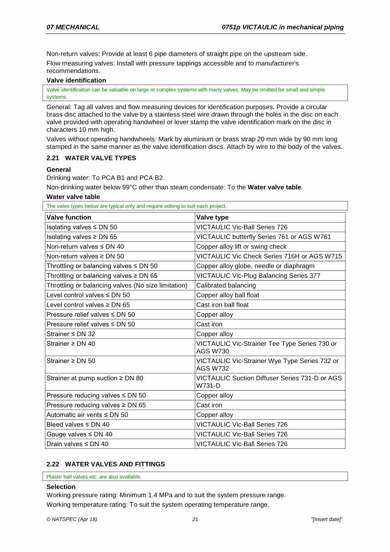
2.21 WATER VALVE TYPES General Drinking water: To PCA B1 and PCA B2. Non-drinking water below 99°C other than steam condensate: To the Water valve table. Water valve table The valve types below are typical only and require editing to suit each project.
Valve function Valve type Isolating valves ≤ DN 50 VICTAULIC Vic-Ball Series 726 Isolating valves ≥ DN 65 VICTAULIC butterfly Series 761 or AGS W761 Non-return valves ≤ DN 40 Copper alloy lift or swing check Non-return valves ≥ DN 50 VICTAULIC Vic Check Series 716H or AGS W715 Throttling or balancing valves ≤ DN 50 Copper alloy globe, needle or diaphragm Throttling or balancing valves ≥ DN 65 VICTAULIC Vic-Plug Balancing Series 377 Throttling or balancing valves (No size limitation) Calibrated balancing Level control valves ≤ DN 50 Copper alloy ball float Level control valves ≥ DN 65 Cast iron ball float Pressure relief valves ≤ DN 50 Copper alloy Pressure relief valves ≤ DN 50 Cast iron Strainer ≤ DN 32 Copper alloy Strainer ≥ DN 40 VICTAULIC Vic-Strainer Tee Type Series 730 or
AGS W730 Strainer ≥ DN 50 VICTAULIC Vic-Strainer Wye Type Series 732 or
AGS W732 Strainer at pump suction ≥ DN 80 VICTAULIC Suction Diffuser Series 731-D or AGS
W731-D Pressure reducing valves ≤ DN 50 Copper alloy Pressure reducing valves ≥ DN 65 Cast iron Automatic air vents ≤ DN 50 Copper alloy Bleed valves ≤ DN 40 VICTAULIC Vic-Ball Series 726 Gauge valves ≤ DN 40 VICTAULIC Vic-Ball Series 726 Drain valves ≤ DN 40 VICTAULIC Vic-Ball Series 726
2.22 WATER VALVES AND FITTINGS
Plastic ball valves etc. are also available.
Selection Working pressure rating: Minimum 1.4 MPa and to suit the system pressure range. Working temperature rating: To suit the system operating temperature range.

07 MECHANICAL 0751p VICTAULIC in mechanical piping
© NATSPEC (Apr 18) 22 "[Insert date]"
Valves for potable water: To AS/NZS 3500.1. Ball valves For quick action (90° turn) isolating function.
Requirement: Provide VICTAULIC Vic-Ball valves. DN 40 to DN 150: VICTAULIC Series 726. ASTM A536, Grade 65-45-12, ductile iron body, chrome plated carbon steel ball and stem, TFE seats, with Fluoroelastomer seals. 800 psi (5515 kPa). Consider including the following Optional style text:
Reduced bore ball valves: Constructed as for full bore ball valves. May be used for drains, air vents and gauges. Butterfly valves For throttling and isolating functions.
Geared operators are specified for butterfly valves used for throttling and balancing. With the flow control characteristics of butterfly valves lever actuators are almost useless for accurate control of flow.
Description: VICTAULIC Master Seal butterfly. DN 50 to DN 300 sizes: - VICTAULIC Vic®-300 MasterSeal™. - Pressure rating: 300 psi CWP (2065 kPa) suitable for bi-directional and dead-end service at full
rated pressure. - Body: Grooved end black enamel coated ductile iron conforming to ASTM A536. - Disc shall be electroless nickel plated ductile iron, stainless steel or aluminium bronze. These are alternatives. Delete those not required.
- Stem: Blowout proof 416 stainless steel stem. - Disc: Offset from the stem centreline to allow full 360 degree seating. - Seat: Pressure responsive EPDM, Lubricated Nitrile or Fluoroelastomer. These are alternatives. Delete those not required.
- Valve bearings: TFE lined fiberglass. - Stem seals: Same grade elastomer as the valve seat. - Actuation: Provide an ISO flange for actuation mounting. - Valve operators: Lever handle or gear operator as documented, with memory stop feature, locking
device, chain wheel, or supplied bare. Valve with EPDM seat is UL classified in accordance with NSF/ANSI 61.
DN 350 to DN 600 sizes: - VICTAULIC Vic®-300 AGS. - Pressure rating: 300 psi (2065 kPa) bubble tight for dead-end or bi-directional service. - Body: AGS grooved ends, polyphenylene sulfide (PPS) coated ductile iron to ASTM A536, Grade
65-45-12. - Disc: PPS coated ductile iron disc to ASTM A536. - Stem: Two piece 17-4 PH stainless steel. - Seat and seal material: To suit intended service. - Bearings: Reinforced PTFE bearings. - Operator: Gear operator with memory stop for throttling, metering or balancing service. Refer to latest published VICTAULIC literature, Butterfly Valve Material Selection section, for liner/seat and disc material recommendations for chemical service.
Operation: - ≤ DN 150: Positive locating operating bar, parallel to the disk with notched plate. - > DN 150: Geared or motorised operator. - All sizes used for throttling and balancing: Geared operators. Construction: - Disk: Ductile iron or stainless steel.

07 MECHANICAL 0751p VICTAULIC in mechanical piping
© NATSPEC (Apr 18) 23 "[Insert date]"
- Seat: Select from pressure responsive EPDM, lubricated nitrile or fluoroelastomer. Refer to VICTAULIC submittal 08.20 for alternatives.
- Stem: Type 416 stainless steel. Non-return valves ≥ DN 50 See AS 1628 Section 6 for swing and lift action limitation.
Requirement: Provide VICTAULIC check valves. Spring assisted check valves: - DN 50 to DN 80 sizes: VICTAULIC Series 716H rated to 365 psi (2517 kPa), with black enamel
coated ductile iron body to ASTM A536, Grade 65-45-12, stainless steel non-slam tilting disc, stainless steel spring and brass shaft, nickel-plated seat surface, 365 psi (2517 kPa).
- DN 100 to DN 300 sizes: VICTAULIC Series 716 rated to 300 psi (2065 kPa), with black enamel coated ductile iron body to ASTM A536, Grade 65-45-12, elastomer encapsulated ductile iron disc suitable for intended service, stainless steel spring and shaft, welded-in nickel seat.
- DN 350 to DN 600: VICTAULIC Series W715. rated to 230 psi (1585 kPa), spring-assisted dual disc check valves with AGS grooved ends, ASTM A536, Grade 65-45-12 coated ductile iron body, EPDM seat bonded to the valve body, 304 stainless steel disc, and 300 series stainless steel spring and shaft.
Horizontal swing DN 50 to DN 100 sizes: VICTAULIC Series 712 rated to 300 psi (2065 kPa), installed horizontally only with ductile iron body to ASTM A536, Grade 65-45-12, Type 316 stainless steel clapper, synthetic rubber bumper and bonnet seals suitable for intended service, stainless steel wetted parts. Venturi check DN 100 to DN 300 sizes: VICTAULIC Series 779 rated to 300 psi (2065 kPa) with black enamel coated ductile iron body, ASTM A536, Grade 65-45-12 with venturi-like taps, elastomer encapsulated ductile iron disc suitable for intended service, stainless steel spring and shaft, welded-in nickel seat. Non-return valves for flow measurement: Provide VICTAULIC Series 779 venturi check valves. These incorporate a venturi and pressure tappings for flow measurement. Available from DN 100 to DN 300.
Non-return valves ≤ DN 40 Disc type: - Body: Stainless steel or bronze. - Disc and spring: Stainless steel. Swing type: To AS 1628. - Body: Bronze. - Plates: Bronze or stainless steel. Globe valves For flow regulation (throttling) and isolating functions. Proprietary valves are available combining throttling/isolating.
Description: Inside screw design. Construction: - Body:
. ≤ DN 50: Bronze.
. > DN 50: Steel. - Stem and gland: Forged brass. Plug valves Sizes: DN 75 to DN 300. Type: VICTAULIC Series 377 rated to 175 psi (1200 kPa) eccentric plug balancing valves with memory stop for throttling, metering or balancing service. Unidirectional bubble-tight shut-off, bi-directional sealing optional, ductile iron body, bonnet, and plug, ASTM A536, Grade 65-45-12. Plug encapsulated with synthetic rubber suitable for intended service. Welded-in nickel seat, stainless steel self-lubricating bearings. Calibrated balancing valves Note tolerance requirements for calibrated balancing valves. Without this information the calibration is questionable and consequently any water balancing done using them is questionable.

07 MECHANICAL 0751p VICTAULIC in mechanical piping
© NATSPEC (Apr 18) 24 "[Insert date]"
Certificates are called for in SUBMISSIONS.
Description: Continuously adjustable graduated with a limit stop for precise setting of the maximum valve opening, a numeric indication of valve opening position and pressure tappings across the variable orifice. Accuracy and repeatability errors: ± 5% or better over the normal measuring range of the valve. Handwheel scale resolution: < 2.5% of full scale. Construction: - Body:
. ≤ DN 50: Dezincification resistant copper alloy of Brinell hardness > 130.
. > DN 50: Cast iron. - Seat: PTFE. Automatic/dynamic system balancing valves Caution should be exercised if using these to control flow to coils fitted with two-way valves. The automatic balancing valves are intended to maintain constant flow whereas the two-way valves work by varying flow. One action therefore fights the other except at maximum system flow rates. The automatic balancing valve may reduce the control authority of the automatic control valve.
On a 2-way valve system, these valves maintain design peak flow but the action of the automatic/dynamic valve is contrary to that of the control valve at reduced flows. As the control valve shuts to reduce coil flow, the automatic/dynamic valve opens to maintain it. The automatic/dynamic valve, in effect, defeats the authority of the control valve over the coil. AIRAH DA24 reports the case of a control valve that disassembled itself because of the vibration caused by this effect.
Description: Pre-calibrated special purpose valve which automatically controls flow rate within ± 5% tolerance, with an internal spring loaded cartridge control mechanism and external tappings for pressure and temperature. Construction: - Body: To suit the piping and fluid as documented. - Cartridge: Passivated stainless steel, spring loaded type, incorporating a variable ported piston
stamped with the manufacturer’s identification number. Pressure relief valves Description: Direct acting, spring loaded with adjustable setting. Standard: To AS 1271. Construction: - Body: Bronze or cast iron as documented. - Valve disc and seat: Bronze. Pressure reducing valves Description: Self-actuated, spring loaded with adjustable setting. Construction: - Body: Bronze or cast iron as documented. - Valve disc and seat: Bronze. Ball float valves Description: Copper or plastic float with stainless steel or copper alloy linkage. Copper alloy valves: To AS 1910. Bronze body, needle and pins. Cast iron valves: Cast iron body, bronze needle and pins. Strainers Strainers at pump suction: VICTAULIC Suction Diffuser. Suction diffusers: - VICTAULIC Series 731D and W731D. - Flanged outlet with grooved inlet connections, rated to 300 psi (2065 kPa). - Ductile iron (ASTM A536) body, 304 stainless steel frame and perforated sheet diffuser with 4 mm
diameter holes. - Removable 20 mesh 304 stainless steel start-up pre-filter, outlets for pressure/temperature drain
connections, and base support boss.

07 MECHANICAL 0751p VICTAULIC in mechanical piping
© NATSPEC (Apr 18) 25 "[Insert date]"
This provides both strainer function and straightens water flow into the pump.
Other strainers: VICTAULIC Tee or Wye strainers. Tee type strainers: - DN 50 to DN 300 sizes: VICTAULIC Style 730 rated to 300 psi (2065 kPa) with of ductile iron body
to ASTM A536, Grade 65-45-12), Type 304 stainless steel frame and mesh removable basket with No. 12 mesh, in DN 50 to DN 75 strainer sizes, or No. 6 mesh, in DN 100 to DN 300 strainer sizes, 57% free open area.
- DN 350 to DN 600 sizes: VICTAULIC Series W730 rated to 300 psi (2065 kPa) with AGS grooved ends and factory fabricated carbon steel body conforming to ASTM A53/A53M, Grade B, carbon steel T-bolt hinged closure/cap, and Type 304 stainless steel frame and mesh basket, with 6 x 6 mesh for DN 350 and DN 400 sizes, and 4 x 4 mesh for DN 450 to DN 600 sizes.
Wye type strainers: - DN 50 to DN 450 sizes: VICTAULIC Style 732 and W732 rated to 300 psi (2065 kPa) with a ductile
iron body to ASTM A536, Grade 65-45-12, and Type 304 stainless steel perforated metal removable baskets with 1.6 mm diameter perforations on DN 50 to DN 75 strainer sizes, 3.2 mm diameter perforations on DN 100 to DN 300 strainer sizes, and 4 mm diameter perforations on DN 350 to DN 450 strainer sizes.
Selection: 15 kPa maximum pressure drop. Consider specifying the size of mesh e.g. for rocks, sand.
Strainers > DN 65 diameter: Fit a 25 mm VICTAULIC ball valve for blowdown. Automatic air vents Description: Float operated. Construction: - Body: Copper alloy. - Float: Non-metallic or stainless steel. - Seat: Stainless steel. Vacuum breaker valves Description: Ball valve operation. Construction: - Body: Copper alloy or stainless steel. - Valve and seat: Stainless steel. Valves at pump discharge Pumps operating in parallel with connected pipe ≥ DN 65: Provide VICTAULIC Triple Service Valve assembly consisting of: - VICTAULIC Series 779 S716 check valve. - VICTAULIC butterfly valve with geared actuator. - VICTAULIC couplings to suit. VICTAULIC Triple Service Valve assemblies provide shut-off, throttling, non-return and, in the Series 779 check valve, calibrated flow measurement.
2.23 STEAM AND CONDENSATE VALVES AND FITTINGS
This clause is relevant to smaller systems and requires editing to suit large and/or high pressure systems.
General Standard: To AS 1271. Selection Working pressure rating: Minimum 1.4 MPa and to suit the system pressure range. Working temperature rating: To suit the system operating temperature range. Limitations on size and type: - Isolating valves: - Globe valves: No limitations. - Gate valves: Cold water and cooled condensate pipe system.

07 MECHANICAL 0751p VICTAULIC in mechanical piping
© NATSPEC (Apr 18) 26 "[Insert date]"
- Ball valves: ≤ DN 50 cold water and cooled condensate pipe system. Ball valves Description: Full bore pattern with handle parallel to the direction of flow when the valve is fully open. DN 40 through DN 150 sizes: VICTAULIC Series 726 rated to 800 psi (5515 kPa) with ASTM A536, Grade 65-45-12, ductile iron body, chrome plated carbon steel ball and stem, TFE seats and Fluoroelastomer seals. Construction: - Body: Bronze. - Ball: Hard chromed brass. - Gland seal: Adjustable. - Seat: PTFE. Consider changing the following Optional style text to Normal style text:
Reduced bore ball valves: Constructed as for full bore ball valves. May be used for drains, air vents and gauges. Non-return valves Disc type: - Body: Stainless steel or bronze. - Disc and spring: Stainless steel. Swing type: - Body: Bronze or cast iron as documented. - Plates: Bronze or stainless steel. Combined sight glass and non-return valve Body: Gun metal. Valve: Stainless steel ball in copper discharge tube. Sight: Toughened glass. Globe valves Description: Inside screw design. Construction: - Body: - ≤ DN 50: Bronze. - > DN 50: Steel. - Stem and gland: Forged brass. Pressure relief valves Description: Direct acting, spring loaded with adjustable setting. Standard: To AS 1271. Construction: - Body: Bronze or cast iron as documented. - Valve disc and seat: Bronze. Pressure reducing valves Description: Pilot actuated, spring loaded with adjustable setting. Construction: - Body: Bronze or cast iron as documented. - Valve disc and seat: Stainless steel. Ball float valves Description: Copper or plastic float with stainless steel or copper linkage. Copper alloy: To AS 1910. Bronze body, needle and pins. Cast iron: Cast iron body, bronze needle and pins. Steam traps Description: Inverted bucket with integral strainer. Other trap types may be preferable for some situations.
07 MECHANICAL 0751p VICTAULIC in mechanical piping
© NATSPEC (Apr 18) 27 "[Insert date]"
Construction: - Body: Cast iron. - Seat: Stainless steel. - Strainers: Stainless steel. Strainers Selection: 15 kPa maximum pressure drop. Construction: - Body: Bronze or cast iron as documented. - Screen: Stainless steel. Strainers > DN 65: Fit a 25 mm ball valve for blowdown. Automatic air vents Description: Float operated. Construction: - Body: Copper alloy. - Float: Non-metallic or stainless steel. - Seat: Stainless steel. Vacuum breaker valves Description: Ball valve operation. Construction: - Body: Copper alloy or stainless steel. - Valve and seat: Stainless steel.
2.24 STEAM SEPARATORS
Consider whether these are needed.
Steam quality is critical for some applications e.g. pre-vacuum sterilisers (but to a lesser extent with downward displacement sterilisers). The diffuser-vortex type of separator is much more efficient (and costly) than the baffle type.
General Requirement: Provide steam separators at the following locations and as documented: - At the main steam header: Baffle type. - At pre-vacuum sterilisers: Diffuser-vortex type. Baffle type Type: Free moisture removed by impingement on internal baffles. Efficiency: > 70% of entering particulates and mist at 30 m/s entering velocity. Construction: Cast iron. Diffuser-vortex type Type: Three stage diffuser-vortex type consisting of a first stage expansion (decreased velocity) separation, second stage with abrupt direction change and centrifugal flow and third stage with vortex separation. Efficiency: > 95% of entering particulates and mist at 30 m/s entering velocity. Size: Provide separators selected for an entering velocity of 25 to 35 m/s at required maximum flow rate. Construction: Fabricated mild steel.
2.25 LIQUID FUEL VALVE TYPES
See 0754 Liquid fuels for discussion of materials. Copper and zinc (including galvanized steel) are not recommended for systems with steel underground tanks or serving diesel engines.
The valve types below are typical only and require editing to suit each project.
If VICTAULIC Vic-Press is used, refer to the VICTAULIC Vic-Press piping system clause.
Liquid fuel valve table Function Valve type Isolating valves ≤ DN 50 VICTAULIC Vic-Ball

07 MECHANICAL 0751p VICTAULIC in mechanical piping
© NATSPEC (Apr 18) 28 "[Insert date]"
Function Valve type Isolating valves ≥ DN 65 VICTAULIC butterfly Non-return valve ≤ DN 50 Copper alloy lift or swing check Non-return valves ≥ DN 65 Cast iron lift or swing check Throttling valves ≤ DN 50 Copper alloy needle Throttling valves ≥ DN 65 Cast iron globe or diaphragm Throttling valves ≤ DN 100 Copper alloy globe or diaphragm Strainer ≤ DN 32 Copper alloy Strainer ≥ DN 40 VICTAULIC Vic-Strainer Tee or Wye type
2.26 LIQUID FUEL VALVES AND FITTINGS Standard Underground petroleum storage systems: To AS 4897. Selection Pressure rating: Minimum 1.4 MPa and to suit system pressure range. Temperature rating: To suit the system operating temperature range. Ball valves For quick action (90° turn) isolating function.
Requirement: Provide VICTAULIC Vic-Ball valves. DN 40 to DN 150: VICTAULIC Series 726 with ASTM A536, Grade 65-45-12, ductile iron body, chrome plated carbon steel ball and stem, TFE seats, with fluoroelastomer seals and rated to 5500 kPa. Consider changing the following Optional style text to Normal style text:
Reduced bore ball valves: Constructed as for full bore ball valves. May be used for drains, air vents and gauges. Non-return valves ≥ DN 50 See AS 1628 Section 6 fir swing and lift action limitation.
Requirement: Provide VICTAULIC check valves. Spring assisted check valves: - DN 50 to DN 80 sizes: VICTAULIC Series 716H rated to 365 psi (2517 kPa), with black enamel
coated ductile iron body to ASTM A536, Grade 65-45-12, stainless steel non-slam tilting disc, stainless steel spring and brass shaft, nickel-plated seat surface, 365 psi (2517 kPa).
- DN 100 to DN 300 sizes: VICTAULIC Series 716 rated to 300 psi (2065 kPa), with black enamel coated ductile iron body to ASTM A536, Grade 65-45-12, elastomer encapsulated ductile iron disc suitable for intended service, stainless steel spring and shaft, welded-in nickel seat.
- DN 350 to DN 600: VICTAULIC Series W715. rated to 230 psi (1585 kPa), spring-assisted dual disc check valves with AGS grooved ends, ASTM A536, Grade 65-45-12 coated ductile iron body, EPDM seat bonded to the valve body, 304 stainless steel disc, and 300 series stainless steel spring and shaft.
Horizontal swing DN 50 to DN 100 sizes: VICTAULIC Series 712 rated to 300 psi (2065 kPa), installed horizontally only with ductile iron body to ASTM A536, Grade 65-45-12, Type 316 stainless steel clapper, synthetic rubber bumper and bonnet seals suitable for intended service, stainless steel wetted parts. Venturi check DN 100 to DN 300 sizes: VICTAULIC Series 779 rated to 300 psi (2065 kPa) with black enamel coated ductile iron body, ASTM A536, Grade 65-45-12 with venturi-like taps, elastomer encapsulated ductile iron disc suitable for intended service, stainless steel spring and shaft, welded-in nickel seat. Non-return valves for flow measurement: Provide VICTAULIC Series 779 venturi check valves. These incorporate a venturi and pressure tappings for flow measurement. Available from DN 100 to DN 300.
Non-return valves ≤ DN 40 Disc type: - Body: Stainless steel or bronze.

07 MECHANICAL 0751p VICTAULIC in mechanical piping
© NATSPEC (Apr 18) 29 "[Insert date]"
- Disc and spring: Stainless steel. Swing type: To AS 1628. - Body: Bronze. - Plates: Bronze or stainless steel. Pressure relief valves Description: Direct acting, spring loaded with adjustable setting. Standard: To AS 1271. Construction: - Body: Bronze or cast iron. - Valve disc and seat: Bronze. Strainers Tee type strainers: - DN 50 to DN 300 sizes: VICTAULIC Style 730 rated to 300 psi (2065 kPa) with of ductile iron body
to ASTM A536, Grade 65-45-12, Type 304 stainless steel frame and mesh removable basket with No. 12 mesh, in DN 50 to DN 75 strainer sizes, or No. 6 mesh, in DN 100 to DN 300 strainer sizes, 57% free open area.
- DN 350 to DN 600 sizes: VICTAULIC Series W730 rated to 300 psi (2065 kPa) with AGS grooved ends and factory fabricated carbon steel body conforming to ASTM A53/A53M, Grade B, carbon steel T-bolt hinged closure/cap, and Type 304 stainless steel frame and mesh basket, with 6 x 6 mesh for DN 350 and DN 400 sizes, and 4 x 4 mesh for DN 450 to DN 600 sizes.
Wye type strainers: - DN 50 to DN 450 sizes: VICTAULIC Style 732 and W732 rated to 300 psi (2065 kPa) with a ductile
iron body to ASTM A536, Grade 65-45-12, and Type 304 stainless steel perforated metal removable baskets with 1.6 mm diameter perforations on DN 50 to DN 75 strainer sizes, 3.2 mm diameter perforations on DN 100 to DN 300 strainer sizes, and 4 mm diameter perforations on DN 350 to DN 450 strainer sizes.
Selection: 15 kPa maximum pressure drop. Consider specifying the size of mesh e.g. for rocks, sand.
Strainers > DN 65 diameter: Fit a 25 mm VICTAULIC ball valve for blowdown. Specify mesh size.
2.27 HOT WATER PANEL RADIATORS
Caution should be exercised when selecting radiators for situations such as health and aged care facilities where their high surface temperature could cause injury. Mandatory surface temperature limits may apply and, if supplied with water at 70 to 85ºC, the surface temperature of a radiator may exceed these limits.
General Construction: Pressed steel with welded joints. Finish: Baked enamel. Air vents General: Provide a key operated air vent integrally fitted at the top of each panel. Mounting General: Mount at least 150 mm clear of floor, with concealed wall mounting brackets. Valves General: Provide a thermostatic control and isolating valve in the inlet and a lock shield isolating valve on the outlet. Consider method of control. Thermostatic valves may not be robust enough for some applications.
Thermostatic control valves are usually fitted on the water entering side to reduce the risk of water hammer.
2.28 INSTRUMENTS – GENERAL Location Expand to suit project or detail on drawings.

07 MECHANICAL 0751p VICTAULIC in mechanical piping
© NATSPEC (Apr 18) 30 "[Insert date]"
Test plugs: Provide in each pipe connection to every heat exchanging device and at other locations documented. Thermometer wells: Provide for each pipe mounted temperature sensor. Pressure tappings: Provide test plugs or valved tappings at each pump, automatic control valve and wherever else shown on the drawings.
2.29 PRESSURE GAUGES General Standard: Bourdon tube type to AS 1349. Scale range: Full scale between 130% and 200% of maximum working pressure. Construction: - Case: Glass filled nylon. Minimum diameter 100 mm. - Lens: UV stabilised polycarbonate. - Dial: UV stabilised polycarbonate. - Indicating pointer: Adjustable. - Configuration: Direct mounting, bottom entry. - Bourdon tube material: Stainless steel for hot water systems. Phosphor bronze for other services. Installation General: Mount gauges vertically and in locations free from vibration. Provide gauge line connection cocks. If necessary, eliminate needle fluctuations caused by pressure fluctuations, by either of the following: - An orifice or restrictor. - A capillary tube pressure pulse damper. Pressure gauge connections: For gauges not permanently connected, seal outlets of isolating valves with flared seal cap nuts. e.g. gauges at commissioning connections.
2.30 THERMOMETERS Dial thermometers Type: Mercury in steel. Accuracy: Within ± 1% of full scale deflection or better. Construction: - Case: Glass filled nylon. Minimum diameter 100 mm. - Lens: UV stabilised polycarbonate. - Dial: UV stabilised polycarbonate. - Indicating pointer: Adjustable. - Bulb: Grade 316 stainless steel. - Configuration: Direct mounting, bottom entry. Installation: Install thermometers vertically, in locations free from vibration, with the bulb in a thermometer well.
2.31 SENSING POINTS Test plugs Selection: Suitable for the service fluid and up to the maximum system pressures and temperatures. Material: Machined brass hexagon body with nordel synthetic rubber cores and gasketed brass hexagon screw cap. Installation: Screwed into sockets welded or brazed to pipes and extended above insulation. Thermometer pockets Arrangement: Arrange for use with glass stem thermometers. Locate so thermometer bulb or sensing tip is close to the centre of the pipe. Construction: Use the same material as the pipe. Weld or braze to pipes. Fill pockets with conductive medium.

07 MECHANICAL 0751p VICTAULIC in mechanical piping
© NATSPEC (Apr 18) 31 "[Insert date]"
Length: Extended above insulation. Pipe enlargement: If thermometer pocket would otherwise decrease the pipe cross sectional area by more than 25%, provide a length of larger diameter pipe to mount the pocket. Thermometer wells Type: Stainless steel, separable type that enables the sensing element to be withdrawn without draining the system. Installation: Screw wells into a boss welded to the pipe, to suit the installed sensing element and extended above insulation. Fill wells with conductive medium.
2.32 WATER FLOW MEASUREMENT
For other measurement devices refer to ISO 5167 parts 1, 2, 3, 4 and 5.
Pitot tube low loss type sensors are specified below and are commonly known as Annubars (trade name). They require less straight pipe and have much lower pressure drop than orifice plates but length of straight before and after as specified by the manufacturer is still critical to achieving their accuracy.
Pitot type sensors Type: Low loss pitot type averaging sensor, with 2 flared isolating valves for connection of pressure lines. Material: Stainless steel. Installation: Conform to the manufacturer’s recommendation for installation, connection and valving. Provide manufacturers recommended straight lengths of pipe upstream and downstream of tapping point. Mount in the piping using an adaptor bushing and welding boss. Accuracy: Within ± 1.5% over the range of flow anticipated. This is a typical value and is affected by the turn down ratio.
Stability: Within ± 0.125% over five years. Repeatability: ± 0.1%. These are typical values. Consult manufacturer's data.
Marking: Provide a stamped tag showing normal, maximum and minimum flows, pipe size, serial number and related data. Flow meters General: Graduated meters incorporating variable pulsation dampening control, integral equalising valve, 2 bleed valves, and a direct reading scale linear to flow rate. Provide nylon connecting hoses suitable for a pressure of 1030 kPa. Connecting hoses are also available in other materials.
Function: To read directly the flow rate in the pipe with a scale appropriate to the expected flow rate. Venturi non-return valve These are an alternative to pitot sensors and flow meters if a non-return (check) valve is provided for other reasons.
Venturi non-return valve: Provide VICTAULIC Series 779 venturi check valves as documented. Installation: Install to VICTAULIC recommendations. Connect differential pressure sensor of other documented device to the integral pressure tappings.
3 EXECUTION
3.1 INSTALLATION General Requirement: Install piping in straight lines at uniform grades with no sags. Arrange to prevent air locks. Provide sufficient VICTAULIC couplings and isolating valves to allow removal of piping and fittings for maintenance or replacement of plant. Layout: Follow the line of walls, ceilings, etc., and include all necessary offsets and arrange to avoid interference with the building or other services. Arrangement: Arrange and support piping so that it remains free from vibrations whilst permitting necessary movements. Minimise the number of joints. Spacing: Provide at least 50 mm clear between pipes, flanges, unions and couplings and between these and building elements, additional to insulation.

07 MECHANICAL 0751p VICTAULIC in mechanical piping
© NATSPEC (Apr 18) 32 "[Insert date]"
This clearance is recommended by BSRIA TN 10/92. See BSRIA TN 10/92 for more details.
Dissimilar metals: Join dissimilar metals with fittings of electrolytically compatible material and as follows: - Flanges: Provide insulating flange kit. Connections Requirement: Arrange connections to plant to permit dismantling of the plant without disturbing other pipes and to permit removal of the plant without cutting or removal of the piping, or cutting or damaging building elements. Provide VICTAULIC couplings at each pipeline component requiring removal for inspection or maintenance. Make all connections to plant by VICTAULIC couplings. 0171 General requirements, SERVICES INSTALLATION, Piping prohibits the embedding of pipes that operate under pressure in concrete or surfacing material. If embedding is to be permitted the instructions to that clause provide some alternative text.
Hydraulic separation of components Requirement: Install pipeline components to manufacturer's recommendations and the following: The following are typical values recommended by pump and valve manufacturers.
- Pump discharge to check valve: ≥ 5 diameters of straight pipe. The flexible connection (if used) and reducer (if used) may be included in calculating this length.
- Before pump suction: Provide a VICTAULIC Suction Diffuser to create straight flow. Accessibility General: To ACCESS FOR MAINTENANCE in 0171 General requirements.
3.2 INSTALLATION - VICTAULIC MECHANICAL JOINTING SYSTEMS General Installers: Use only installation personnel trained by VICTAULIC certified trainer. Training of installation personnel: On site, by a VICTAULIC certified trainer representative who is a direct employee of VICTAULIC including training in the use of grooving tools, application of groove, and product installation. Evidence of this is to be provided in SUBMISSIONS.
Manufacturer’s recommendations: Install in accordance with manufacturer’s latest recommendations. Follow the instructions listed in the latest published Field Installation Handbooks. Pipe Preparation: Provide piping grooved on machines supplied by VICTAULIC or machines meeting VICTAULIC specifications. Use tools of the correct size for the application and in accordance with the VICTAULIC recommendations. Joints: Install couplings in the neutral position at ambient temperature to minimise stress due to expansion and contraction of the pipe. Pipe ends: Clean and free from indentations, projections and roll marks in the area from pipe end to groove. Required for proper gasket sealing.
Completion of coupling installation: When visual metal-to-metal contact is reached.
3.3 CLEANING External preparation General: Remove scale, rust, burrs and grease and make sure that surfaces are clean and dry. Protection: During construction, prevent the entry of foreign matter into the piping system by temporarily sealing the open ends of pipes and valves with purpose-made covers of pressed steel or rigid plastic.
3.4 SUPPORTS Support systems General: Provide hangers, brackets, saddles, clips, and support system components, incorporating provisions for adjustment of spacing, alignment, grading and load distribution. Support pipework from associated equipment or building structure. Support valves, strainers and major line fittings so that no load is placed on adjacent pipes or transmitted to them during operation and maintenance. Support type: Proprietary metallic-coated steel channel section with clamps and hangers sized to match external diameter of pipe being supported.

07 MECHANICAL 0751p VICTAULIC in mechanical piping
© NATSPEC (Apr 18) 33 "[Insert date]"
Vertical pipes: Provide anchors and guides to maintain long pipes in position, and supports to balance the mass of the pipe and its contents. Saddles: Saddle type supports may only be used for pipes no more than DN 25. Dissimilar metals: If pipe and support materials are dissimilar, provide industrial grade electrically non-conductive material securely bonded to the pipe to separate them. Provide fixings of electrolytically compatible material. Uninsulated pipes: Clamp piping supports directly to pipes, subject to electrical isolation of dissimilar metals. Insulated pipes: - Spacers: Provide spacers at least as thick as the insulation between piping supports and pipes.
Extend either side of the support by at least 20 mm. - Spacer material: Rigid insulation material of sufficient strength to support the piping and suitable for
the temperature application. The temperature limit for cork insulation is 90°C so it may not be suitable for some hot pipes despite this being a common practice. Alternatives to cork include high density (> 100 kg/m3) polyurethane and phenolic foam as well as glass wool, rock wool and polyester.
- Vapour barriers: For cold pipes, apply aluminium foil tape over the circumference of the spacer to form a vapour barrier. Fit to spacer before installation of the bracket on the pipe.
- Metal sheathing: Provide a 0.55 mm thick metallic-coated steel band between the aluminium foil tape and the support for the full width of the spacer.
Coordinate vapour barriers and metal sheathing with 0752 Mechanical piping insulation. For cold pipes the vapour barrier (and metal sheathing if documented) allows the pipe insulator to continue the metal sheathing and vapour barrier respectively, without having to remove the support bracket.
Support spacing Pipe support spacing requirements vary considerably from application to application. For more information see NATSPEC TECHnote DES 019.
See AS 4041 Table 3.28.2 for spacing of steel pipe supports. See also AS/NZS 5601.1 Table 5.5, for gas pipe support spacing, which also conflicts (more conservative).
Ferrous pipes: To AS 4041 Table 3.28.2. Copper pipes: To AS 4809 Table 6.2. Other non-ferrous pipe: To AS/NZS 3500.1 Table 5.6.4. VICTAULIC pipe systems: Provide a support within 1 m of each coupling and in accordance with VICTAULIC Field Installation Handbooks. Hanger size table Outside diameter of pipe or sheathing (mm)
Minimum hanger diameter (mm): Light series
Minimum hanger diameter (mm): Heavy series
< 20 6 6 ≥ 20, < 35 10 10 ≥ 35, < 65 12 12 ≥ 65, < 120 12 16 ≥ 120, < 220 16 16 ≥ 220, < 275 16 20 ≥ 275, < 325 20 24 ≥ 325, < 410 24 30 Delete if conflict with selected proprietary system. For gas pipes, see AS/NZS 5601.1 Table 5.5.
3.5 EXPANSION AND COMPACTION
See the 0171 General requirements worksection VIBRATION SUPPRESSION for vibration isolation. For proprietary devices e.g. articulated or axial bellows or ball joints, show on the drawings.
Coordinate design of supports with the structural engineer.

07 MECHANICAL 0751p VICTAULIC in mechanical piping
© NATSPEC (Apr 18) 34 "[Insert date]"
General Requirement: VICTAULIC Flexible couplings, pipe anchors, offsets and pipe guides to accommodate expansion and contraction, and to minimise the transmission vibration and noise to building structures. If sufficient flexibility cannot be achieved with standard VICTAULIC couplings, provide additional flexibility using VICTAULIC Style 155 Expansion Joints. Expansion joints Selection: - DN 50 to DN 150: VICTAULIC Style 150 Mover packless, gasketed, type with grooved end
telescoping body, suitable for axial end movement to 80 mm at up to 2400 kPa. - DN 20 and larger: VICTAULIC Style 155 expansion joint consisting of a series of grooved end
nipples joined with flexible-type couplings. Provide the number of couplings or nipples used in the joint to suit the joint movement and expansion required.
Gaskets: Provide gasket style, and elastomeric material and grade, suitable for the documented service. Anchors and guides: Locate anchors and guides to VICTAULIC recommendations. Weld or securely clamp anchors to bare pipe. If limitations in the strength of structures prevent the use of expansion devices and anchors, arrange piping to move in lateral and linear directions (e.g. at bends) while not deviating from gradients. In addition to standard VICTAULIC jointing practice, VICTAULIC can supply Style 155 expansion joints consisting of a series of VICTAULIC couplings joined by short nipples.
Flexible connections General: Minimise the transmission of vibration and noise through the piping. Isolate vibrating sources as follows: - Connections to major plant items: Provide 3 VICTAULIC Flexible couplings. - Elsewhere: VICTAULIC Flexible couplings or flexible reinforced nylon hose. Flexible couplings: Use in locations where vibration attenuation and stress relief are required. Flexible couplings may be used in lieu of flexible connectors at equipment connections. Provide three couplings for each connector, placed in close proximity to the vibration source. The inherent flexibility of VICTAULIC Flexible couplings means that they can control vibration transmission without the need for separate flexible connections.
3.6 SLEEVES
See also BUILDING PENETRATIONS in 0171 General requirements.
General Location: Provide sleeves that permit normal pipe movement through walls, floors, and other building elements. Cover plates General: Where exposed to view provide cover plates fixed to the pipe or insulation sheathing and free to move with respect to sleeve and building surface. Material: Non-ferrous metal, finished to match the pipe, or of stainless steel, close fitting and firmly fixed in place. Cover plate sizes table Nominal pipe size, DN Cover plate diameter < 20 65 mm ≥ 20, < 50 100 mm ≥ 50 50 mm larger than pipe
3.7 JOINTS General Requirement: Minimise the number of joints. Demountable joints Show where required on the drawings.
07 MECHANICAL 0751p VICTAULIC in mechanical piping
© NATSPEC (Apr 18) 35 "[Insert date]"
Requirement: Locate as follows: - At connections to mechanically cleanable heat transfer vessels and pumps. - At maintenance locations. Pipes ≥ DN 25: VICTAULIC couplings. For connections requiring frequent disconnection, consider VICTAULIC Style 78 Snap-Joint coupling.
Flanged joints Requirement: Provide flanges only where required for connection to equipment supplied with flanged connections. Flanges: Provide VICTAULIC Vic-Flange adapter and VICTAULIC coupling. Bolting: To AS 2129 Appendix C and AS 2528. - Material: - Corrosive environments: Material with equivalent corrosion resistance to, and compatible with, the
flanges. - Non corrosive environments: Zinc-plated steel. Avoid cadmium plating due to its toxicity.
Flange jointing material: Preformed proprietary type at least 0.8 mm thick. Installation: Install flanges square with the run of pipe and aligned parallel to each other. Do not correct misalignment by bolting. Screwed joints General: To AS ISO 7.1. Do not provide long screws or barrel nipples. Seal threads of screwed connections with degreased PTFE tape or a thread sealing compound.
3.8 DRAINS, VENTS AND GRADING
Preferably show types and locations on the drawings.
Drains Water systems: Provide dirt pockets with valved drains to the bottom of riser piping and as necessary to drain liquids completely from piping and permit cleaning. To permit access to the full bore of the pipe for cleaning, provide a blank flange or screwed cap at the bottom of the dirt pocket matching the jointing system and pipe size on the rest of the piping. Open piping systems: Arrange piping and equipment including drain lines so that the system can be fully drained with no undrainable (dead) sections except traps. This is required by AS/NZS 3666.1 clause 4.7.
Other drains: Provide drains to drip trays, automatic air vents and equipment requiring routine draining. Drain size: ≥ DN 20 and to the Drain size table or to match the equipment drain size, if larger. Drain points: Pipe drains to discharge points via air breaks. Air inlet points for draining systems: Provide vents for admitting air at high points in the system. Drain size table Nominal size of pipe to be drained, DN Nominal size of drain and valve, DN (minimum) > 50, ≤ 100 20 > 100, ≤ 150 25 > 150, ≤ 300 32 > 300 50 Air release vents Preferable show types e.g. vent pipe, valve, air bottle, on the drawings.
Vent type: Provide manual vents except where automatic vents are documented. Location: Provide 15 mm minimum size air release vents at the following locations in water systems: - High points of the system. - Sections of the piping in which air may collect.

07 MECHANICAL 0751p VICTAULIC in mechanical piping
© NATSPEC (Apr 18) 36 "[Insert date]"
- Upstream from each item of heat exchange equipment. Water system risers: Provide a 150 mm high riser set vertically from the pipe and fabricated from the same diameter and material as the pipe. Provide an automatic air vent at the top of the riser. Grading Water systems: Grade to rise in the direction of flow to points of air venting, except where the water piping is exposed in a run with other services, in which case run the water piping to the same grade as the other services. - Minimum grade: 1 in 200. Show gradients on drawings.
3.9 UNDERGROUND PIPING – METAL
Check statutory requirements for pipes outside the property.
It may be necessary to specify a method for marking the type, location and direction of concealed piping e.g. (for underground lines) engraved brass plates set in concrete blocks at ground level.
Proximity to other services General: Separate underground piping from electrical cables and gas pipes, by at least 300 mm. Installation Pipe underlay: Bed piping on a continuous underlay of bedding material, at least 75 mm thick after compaction. Grade the underlay evenly to the gradient of the piping. Bedding material: Sand free from material retained on a 13.2 mm sieve. Chases: If necessary, form chases to prevent projections such as sockets and flanges from bearing on the trench bottom or underlay. Other services: Separate underground piping from electrical cables and other services by ≥ 300 mm. Pipe surrounds General: Place the material in the pipe surround in layers less than 200 mm loose thickness and compact without damaging or displacing the piping. Protection: Lay continuously concrete tiles more than 25 mm thick, or PVC tape at least 3 mm thick, in the overlay, 50 to 75 mm clear of the piping, for the length of the piping. Warning tape: During backfilling lay plastic warning tape 300 mm above buried piping, for the full length of the piping. - Type: Minimum 100 mm width. Valves Install in underground control boxes. Corrosion protection Protection: Either encase piping in continuous PVC-U watertight pipe or provide continuous wrapping over all pipe and fittings using proprietary petroleum taping material installed in accordance with manufacturer's recommendations. See also CORROSION RESISTANCE in 0171 General requirements.
Petroleum taping For proprietary petroleum taping material, (e.g. Denso), typical installation may be documented by changing this Optional style text to Normal style text.
Application: Thoroughly clean and Prime the pipe, then cover fittings and joints with petroleum based mastic. Wrap the pipe and fittings with petroleum based tape to provide a continuous barrier to prevent ingress of water. Provide 50% minimum overlap of tape. Irregular profiles: If necessary, contour irregular profiles such as weld beads, shoulders, boltheads, nuts and the like with proprietary, petroleum-based corrosion protective mastic strip. Inspection: On completion, have the treatment system inspected by the manufacturer and submit evidence of the manufacturer’s approval.
3.10 TESTING Completion tests Cold water: To AS/NZS 3500.1 Section 17. Wastewater: To AS/NZS 3500.2 Section 13.

07 MECHANICAL 0751p VICTAULIC in mechanical piping
© NATSPEC (Apr 18) 37 "[Insert date]"
Pressure piping as defined by AS 4041: Hydrostatic test. Condensate drains from cooling coils: Hydrostatic testing is not required. Although exempt from hydrostatic testing, drain integrity testing is required in the respective plant worksections e.g. 0721 Packaged air conditioning and 0724 Air handling plant – combined.
Hydrostatic testing Preparation for testing: Isolate items of equipment not designed to withstand test pressures. Leave pipe joints exposed to enable observation during tests. Secure pipes and fittings in position to prevent movement during tests. Restrain expansion bellows. Water pre-treatment: Conform to 0753 Water treatment. For steel piping, introduce corrosion inhibiting chemicals. Use chemicals from a water treatment specialist in conformance with the specialist’s instructions and under the specialist’s supervision. Leave pre-treated water in the system until the system is ready for chemical cleaning and flushing. Coordinate with 0753 Water treatment. This paragraph is intended to complement the corresponding clause in 0753 Water treatment, and assumes certain contractual demarcations.
Procedure: Test completed piping systems including equipment designed to withstand test pressures. Isolate equipment not designed to withstand the test pressure. Test criteria: No leaks or loss of pressure over the test period after taking account of changes in ambient temperature. Test pressures: To AS 4041. AS 4041 includes in its definition of pressure piping a wide range of systems including fuel oil, low pressure gases and compressed air over 70 kPa. Consider extending hydrostatic testing to include systems not covered by AS 4041, and the PCA, such as vacuum piping and low pressure compressed air piping.
3.11 COMPLETION Corrective action Requirement: Remove and replace any improperly installed products.
4 SELECTIONS
Schedules are a way of documenting a selection of proprietary or generic products or systems by their properties. Indicate their locations here and/or on the drawings. Refer to NATSPEC TECHnote GEN 024 for guidance on using and editing schedules.
4.1 PIPING Piping schedule Property P1 P2 P3 Service
Material
Class VICTAULIC is a pipe jointing company with solutions to suit almost any service provided the pipe wall thickness is sufficient for the application pressure and the appropriate gasket is selected to match the flowing media. All piping services for fluids and gases in HVAC systems including fuel lines for diesel engines and compressed air can be joined with VICTAULIC product.
Edit schedule to suit project.
Consider the following:
• Pressure/temperature limits i.e. working pressure and test pressure (kPa), and working temperature range (°C).
• Piping material e.g. cooper, steel, PVC-U.
• AS 4041 piping class.
• AS 1432 Type (A, B or D).
• Pressure range.
• Temperature range.
• Materials and sizes, including grade or type, nominal (pipe) size, wall thickness, and pipe end finish.
• Finishes, including identification e.g. full length painted colour, painted bands or pipeline markers.

07 MECHANICAL 0751p VICTAULIC in mechanical piping
© NATSPEC (Apr 18) 38 "[Insert date]"
Typical schedule contents are as follows:
• Chilled water: Steel or copper.
• Condenser water - Open circuit: Stainless steel, copper, PVC-U or ABS.
• Condenser water - Closed circuit: Steel or copper.
• Air conditioning condensate drains as far as floor waste or tundish: Copper or PVC-U.
• Domestic cold water and drains: Copper.
• Low pressure heating water < 100°C: Steel or copper.
• High pressure hot water ≥ 100°C: Steel.
• Steam above atmospheric pressure: Steel.
• Steam condensate: Copper to AS 1432 Type A.
Adapting the Piping schedule for design and construct projects Insert the information described in the above guidance.
4.2 HOT WATER PANEL RADIATORS Hot water panel radiator schedule Property R1 R2 R3 Location
Type
Nominal width (mm)
Nominal height (mm)
Minimum heat output (watts): At room temperature (°C)
Minimum heat output (watts): At water entering temperature (°C)
Minimum heat output (watts): At water leaving temperature (°C)
R1, R2, R3: These designate each instance or type of the item scheduled. Edit to align with the project’s codes or tags.
Edit codes in the Schedule to match those on drawings.
Type: e.g. finned, panel, hospital, sectional cast iron.
Adapting the Hot water panel radiator schedule for design and construct projects If the contractor is to calculate the required performance and to select the equipment, the SELECTIONS schedules can be used to set generic selection parameters. Note that the documents should include sufficient information for items to be determined by the contractor, for example from documented performance parameters and architectural drawings. For these items, insert suitable text, e.g. To the documented requirements. The Hot water panel radiator schedule can then form the basis of the contractor's submissions with the text replaced by design values:
• Nominal width (mm).
• Nominal height (mm).
Minimum heat output (watts) at:
• Room temperature (°C).
• Water entering temperature (°C).
• Water leaving temperature (°C).
REFERENCED DOCUMENTS The following documents are incorporated into this worksection by reference: AS ISO 7 Pipe threads where pressure-tight joints are made on the threads AS ISO 7.1 2008 Dimensions, tolerances and designation AS 1074 1989 Steel tubes and tubulars for ordinary service AS 1271 2003 Safety valves, other valves, liquid level gauges, and other fittings for boilers and unfired
pressure vessels AS 1349 1986 Bourdon tube pressure and vacuum gauges

07 MECHANICAL 0751p VICTAULIC in mechanical piping
© NATSPEC (Apr 18) 39 "[Insert date]"
AS 1432 2004 Copper tubes for plumbing, gasfitting and drainage applications AS/NZS 1477 2017 PVC pipes and fittings for pressure applications AS 1628 1999 Water supply - Metallic gate, globe and non-return valves AS 1910 2004 Water supply - Float control valves for use in hot and cold water AS/NZS 2032 2006 Installation of PVC pipe systems AS 2129 2000 Flanges for pipes, valves and fittings AS 2528 1982 Bolts, studbolts and nuts for flanges and other high and low temperature applications AS/NZS 3500 Plumbing and drainage AS/NZS 3500.1 2015 Water services AS/NZS 3500.2 2015 Sanitary plumbing and drainage AS/NZS 3518 2013 Acrylonitrile butadiene styrene (ABS) compounds, pipes and fittings for pressure
applications AS 3688 2016 Water supply - Metallic fittings and end connectors AS/NZS 3690 2009 Installation of ABS pipe systems AS/NZS 3879 2011 Solvent cements and priming fluids for PVC (PVC-U and PVC-M) and ABS and ASA
pipes and fittings AS 4041 2006 Pressure piping AS/NZS 4130 2009 Polyethylene (PE) pipes for pressure applications AS/NZS 4441 2017 Oriented PVC (PVC-O) pipes for pressure applications AS 4809 2017 Copper pipe and fittings - Installation and commissioning AS 4897 2008 The design, installation and operation of underground petroleum storage systems PCA 2016 National Construction Code Series Volume 3 - Plumbing Code of Australia PCA B1 2016 Water services - Cold water services PCA B2 2016 Water services - Heated water services ANSI B31 Pressure piping ANSI B31.1 2016 Power piping ANSI B31.9 2017 Building services piping API Spec 5L 2012 Specification for line pipe ASME B16.9 2012 Factory-Made Wrought Buttwelding Fittings ANSI/ASME B36.19M 2004 Stainless steel pipe ASTM A234 2017 Standard Specification for Piping Fittings of Wrought Carbon Steel and Alloy Steel for
Moderate and High Temperature Service ASTM A312/A312M 2016 Standard specification for seamless, welded and heavily cold worked austenitic
stainless steel pipes ASTM A403 2016 Standard Specification for Wrought Austenitic Stainless Steel Piping Fittings ASTM A564 2013 Standard Specification for Hot-Rolled and Cold-Finished Age-Hardening Stainless Steel
Bars and Shapes ASTM A153 2016 Standard Specification for Zinc Coating (Hot-Dip) on Iron and Steel Hardware ASTM A395 1999 Standard Specification for Ferritic Ductile Iron Pressure-Retaining Castings for Use at
Elevated Temperatures ASTM A53/A53M 2012 Standard Specification for Pipe, Steel, Black and Hot-Dipped, Zinc-Coated, Welded and
Seamless ASTM A183 2014 Standard Specification for Carbon Steel Track Bolts and Nuts ASTM A193/A193M 2017 Standard Specification for Alloy-Steel and Stainless Steel Bolting for High Temperature
or High Pressure Service and Other Special Purpose Applications ASTM A276/A276M 2017 Standard Specification for Stainless Steel Bars and Shapes ASTM A351/A351M 2016 Standard Specification for Castings, Austenitic, for Pressure-Containing Parts ASTM A449 2014 Standard Specification for Hex Cap Screws, Bolts and Studs, Steel, Heat Treated,
120/105/90 ksi Minimum Tensile Strength, General Uses ASTM A536 2014 Standard Specification for Ductile Iron Castings ASTM A743/A743M 2017 Standard specification for castings, iron-chromium, iron-chromium-nickel, corrosion
resistant, for general application ASTM A744/A744M 2013 Standard Specification for Castings, Iron-Chromium-Nickel, Corrosion Resistant, for
Severe Service ASTM B733 2015 Standard Specification for Autocatalytic (Electroless) Nickel-Phosphorus Coatings on
Metal ASTM B633 2015 Standard Specification for Electrodeposited Coatings of Zinc on Iron and Steel ASTM D2000 2017 Standard Classification System for Rubber Products in Automotive Applications ASTM F436 2011 Standard Specification for Hardened Steel Washers NFPA 13 2016 Standard for the Installation of Sprinkler Systems NSF/ANSI 61 2016 Drinking Water System Components - Health Effects EN 10216 Seamless steel tubes for pressure purposes. Technical delivery conditions. EN 10216-1 2013 Non-alloy steel tubes with specified room temperature properties EN 10217 Welded steel tubes for pressure purposes - Technical delivery conditions EN 10217-1 2002 Non-alloy steel tubes with specified room temperature properties The following documents are mentioned only in the Guidance text: AS/NZS 3666 Air-handling and water systems of buildings - Microbial control AS/NZS 3666.1 2011 Design, installation and commissioning AS/NZS 5601 Gas installations AS/NZS 5601.1 2013 General installations AIRAH DA16 1994 Water piping AIRAH DA24 2003 Water systems balancing NATSPEC DES 019 2009 Pipe support spacing NATSPEC GEN 006 2007 Product specifying and substitution NATSPEC GEN 024 2015 Using NATSPEC selections schedules

07 MECHANICAL 0751p VICTAULIC in mechanical piping
© NATSPEC (Apr 18) 40 "[Insert date]"
NATSPEC TR 01 2017 Specifying ESD NATSPEC TR 03 2015 Specifying Design and Construct for Mechanical services BSRIA TN 10 1992 Space allowances for building services distribution systems: Detail design stage ISO 5167 Measurement of fluid flow by means of pressure differential devices inserted in circular
cross-section conduits running full