03-10-2011 110815 photovoltaic-application-guide
TRANSCRIPT
Photovoltaic Application GuideISSUE 2011
www.socomec.com


CONTENTS
Glossary of common photovoltaic terms
Protecting photovoltaic generators
Protecting against electrical shocks ___________________________________________9
Protecting photovoltaic generators againstvoltage surges _____________________________________________________________________________________________9
Current surges on photovoltaic generators _______________________ 11
Protecting photovoltaic generators againstcurrent surges _______________________________ 13
Protecting photovoltaic installationsfrom damage ________________________________ 17
Photovoltaic installations
General photovoltaic principles ______________________________________________________4
Photovoltaic architecture ____________________________________________________________________5
DC / AC galvanic separation ____________________________________________________________7
Disconnecting photovoltaic generators
Disconnection ______________________________________________________________________________________________8
Emergency disconnection _________________________________________________________________8
Fire service disconnection __________________________________________________________________8
4 SOCOMEC 2011 photovoltaic technical catalogue
Photovoltaic installations
SOCOMEC 2011 photovoltaic technical catalogue
General photovoltaic principles
The photovoltaic cell
The infl uence of light and temperature
cate
c-pv
004
a g
b
cate
c-pv
003
a g
b
cate
c-pv
001
a g
b
Doped zone N
300 µm
Photons
Doped zone P(silicon strip)
Current
MPP
75 °C
50 °C
25 °C
0 °C
Voltage
Current
MPP
Voltage
1000 Wm²
800Wm²
600Wm²
400Wm²
200Wm²
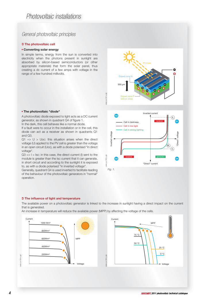
Converting solar energy
In simple terms, energy from the sun is converted into electricity when the photons present in sunlight are absorbed by silicon-based semiconductors (or other appropriate materials) that form the solar panel, thus creating a dc current of a few amps with voltage in the range of a few hundred millivolts.
The available power on a photovoltaic generator is linked to the increase in sunlight having a direct impact on the current that is generated.An increase in temperature will reduce the available power (MPP) by affecting the voltage of the cells.
The photovoltaic "diode"
A photovoltaic diode exposed to light acts as a DC current generator, as shown in quadrant Q4 of fi gure 1. In the dark, this cell behaves like a normal diode. If a fault were to occur in the installation or in the cell, this diode can act as a receiver as shown in quadrants Q1 and Q3.Q1 => U > Uoc: this situation arises when the direct voltage (U) applied to the PV cell is greater than the voltage in an open circuit (Uoc), as with a diode polarised "in direct voltage".Q3 => I > Isc: in this case, the direct current (I) sent to the module is greater than the Isc current that it can generate, in short circuit and according to the sunlight it is exposed to, as with a diode polarised "in inverted voltage".Generally, quadrant Q4 is used inverted to facilitate reading of the behaviour of the photovoltaic generators in "normal" operation.
cate
c-pv
002
a g
b
Inverted current
Cell in darkness
Cell in low light
Cell in strong lighting
receiver
receiver generator
Inve
rted
vol
tage
“Direct” current
“Dire
ct”
volta
ge
UOC
ISCR
Q1
Q4
Q2
Q3
I SC
Fig. 1.
5SOCOMEC 2011 photovoltaic technical catalogueSOCOMEC 2011 photovoltaic technical catalogue
Photovoltaic installations
Photovoltaic architecture
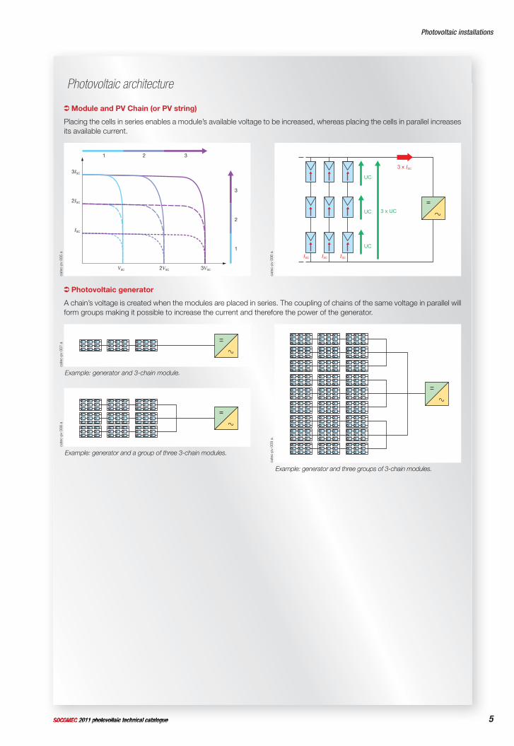
Module and PV Chain (or PV string)
Photovoltaic generator
Placing the cells in series enables a module’s available voltage to be increased, whereas placing the cells in parallel increases its available current.
A chain’s voltage is created when the modules are placed in series. The coupling of chains of the same voltage in parallel will form groups making it possible to increase the current and therefore the power of the generator.
cate
c-pv
006
aca
tec-
pv 0
09 a
ISC ISC ISC
3 x ISC
3 x UC
UC
UC
UC
cate
c-pv
005
aca
tec-
pv 0
07 a
cate
c-pv
008
a
3ISC
2ISC
ISC
3
2
1
1 2 3
V0C 2V0C 3V0C
Example: generator and 3-chain module.
Example: generator and a group of three 3-chain modules.
Example: generator and three groups of 3-chain modules.
6 SOCOMEC 2011 photovoltaic technical catalogue
Photovoltaic installations
SOCOMEC 2011 photovoltaic technical catalogue
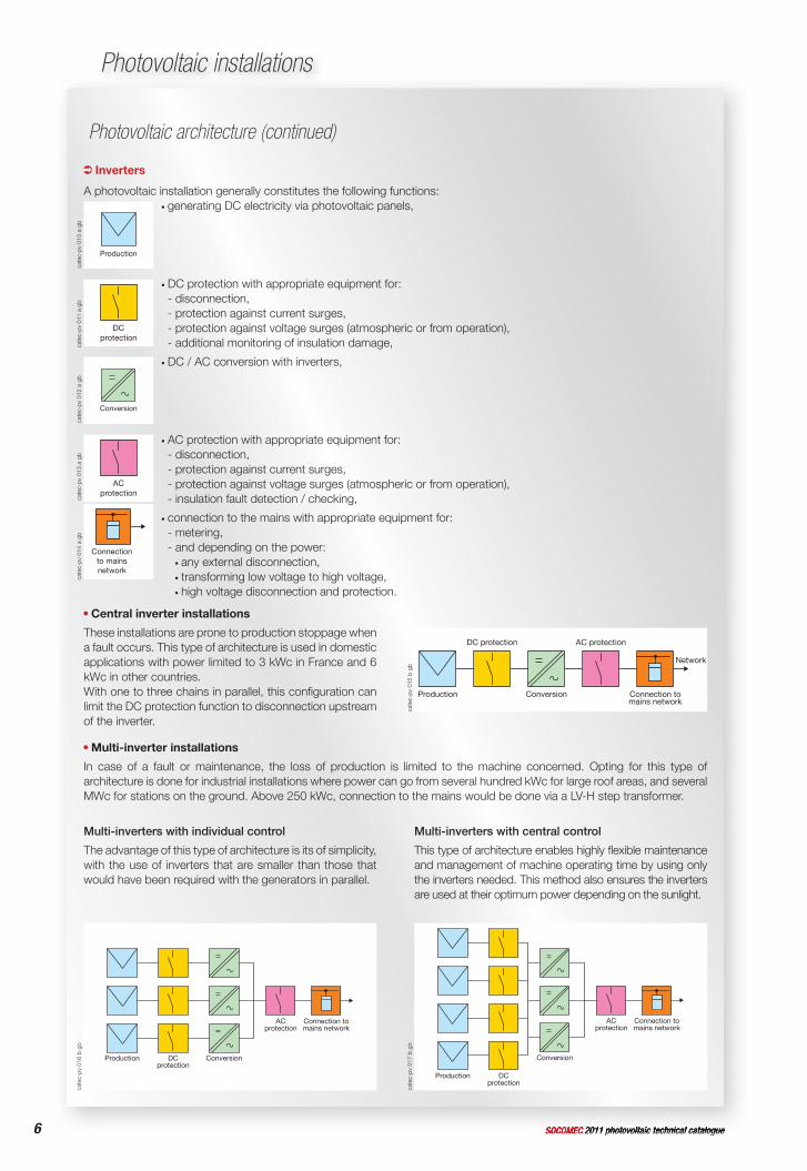
Central inverter installations
These installations are prone to production stoppage when a fault occurs. This type of architecture is used in domestic applications with power limited to 3 kWc in France and 6 kWc in other countries.With one to three chains in parallel, this confi guration can limit the DC protection function to disconnection upstream of the inverter.
Multi-inverter installations
In case of a fault or maintenance, the loss of production is limited to the machine concerned. Opting for this type of architecture is done for industrial installations where power can go from several hundred kWc for large roof areas, and several MWc for stations on the ground. Above 250 kWc, connection to the mains would be done via a LV-H step transformer.
Inverters
A photovoltaic installation generally constitutes the following functions:
Production
generating DC electricity via photovoltaic panels,
DCprotection
DC protection with appropriate equipment for:- disconnection,- protection against current surges,- protection against voltage surges (atmospheric or from operation),- additional monitoring of insulation damage,
Conversion
DC / AC conversion with inverters,
ACprotection
AC protection with appropriate equipment for:- disconnection,- protection against current surges,- protection against voltage surges (atmospheric or from operation),- insulation fault detection / checking,
Connectionto mainsnetwork
connection to the mains with appropriate equipment for:- metering,- and depending on the power:
any external disconnection, transforming low voltage to high voltage, high voltage disconnection and protection.
Photovoltaic architecture (continued)
cate
c-pv
016
b g
b
cate
c-pv
017
b g
bca
tec-
pv 0
15 b
gb
Network
Production
DC protection
Conversion
AC protection
Connection tomains network
cate
c-pv
010
a g
bca
tec-
pv 0
11 a
gb
cate
c-pv
012
a g
bca
tec-
pv 0
13 a
gb
cate
c-pv
014
a g
b
Production DCprotection
Conversion
ACprotection
Connection tomains network
Production DCprotection
Conversion
ACprotection
Connection tomains network
Multi-inverters with individual control
The advantage of this type of architecture is its of simplicity, with the use of inverters that are smaller than those that would have been required with the generators in parallel.
Multi-inverters with central control
This type of architecture enables highly fl exible maintenance and management of machine operating time by using only the inverters needed. This method also ensures the inverters are used at their optimum power depending on the sunlight.
7SOCOMEC 2011 photovoltaic technical catalogueSOCOMEC 2011 photovoltaic technical catalogue
Photovoltaic installations
DC / AC galvanic separation
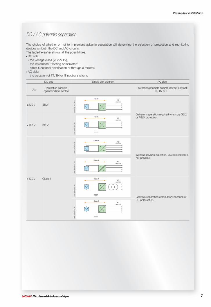
The choice of whether or not to implement galvanic separation will determine the selection of protection and monitoring devices on both the DC and AC circuits.The table hereafter shows all the possibilities: DC side:- the voltage class (VLV or LV),- the installation, "fl oating or insulated",- direct functional polarisation or through a resistor. AC side:- the selection of TT, TN or IT neutral systems
DC side Single unit diagram AC side
Udc Protection principleagainst indirect contact
Protection principle against indirect contact: IT, TN or TT
≤120 V SELV
TBTSAC
section
Galvanic separation required to ensure SELV or PELV protection.
≤120 V PELV
TBTPAC
section
>120 V Class II
Class IIAC
section
Without galvanic insulation, DC polarisation is not possible.
Class IIAC
section
Class IIAC
section
Galvanic separation compulsory because of DC polarisation.Class II
ACsection
cate
c-pv
018
a g
bca
tec-
pv 0
19 a
gb
cate
c-pv
020
a g
bca
tec-
pv 0
21 a
gb
cate
c-pv
022
a g
bca
tec-
pv 0
23 a
gb
cate
c-pv
017
a fr
8 SOCOMEC 2011 photovoltaic technical catalogue
Disconnecting photovoltaic generators
SOCOMEC 2011 photovoltaic technical catalogue
Disconnecting photovoltaic generators
Disconnection
Emergency disconnection
Fire service disconnection
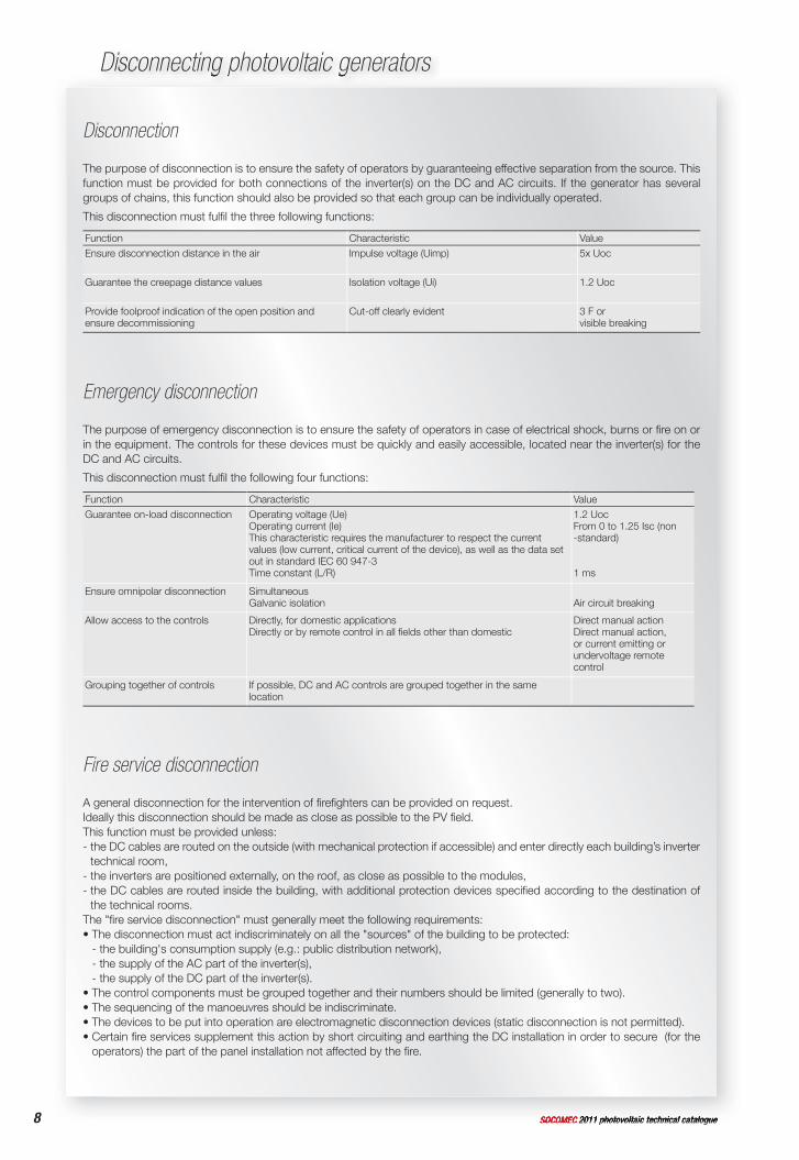
The purpose of disconnection is to ensure the safety of operators by guaranteeing effective separation from the source. This function must be provided for both connections of the inverter(s) on the DC and AC circuits. If the generator has several groups of chains, this function should also be provided so that each group can be individually operated.
This disconnection must fulfi l the three following functions:
Function Characteristic ValueEnsure disconnection distance in the air Impulse voltage (Uimp) 5x Uoc
Guarantee the creepage distance values Isolation voltage (Ui) 1.2 Uoc
Provide foolproof indication of the open position and ensure decommissioning
Cut-off clearly evident 3 F or visible breaking
The purpose of emergency disconnection is to ensure the safety of operators in case of electrical shock, burns or fi re on or in the equipment. The controls for these devices must be quickly and easily accessible, located near the inverter(s) for the DC and AC circuits.
This disconnection must fulfi l the following four functions:
Function Characteristic ValueGuarantee on-load disconnection Operating voltage (Ue)
Operating current (Ie) This characteristic requires the manufacturer to respect the current values (low current, critical current of the device), as well as the data set out in standard IEC 60 947-3Time constant (L/R)
1.2 UocFrom 0 to 1.25 Isc (non -standard)
1 ms
Ensure omnipolar disconnection SimultaneousGalvanic isolation Air circuit breaking
Allow access to the controls Directly, for domestic applicationsDirectly or by remote control in all fi elds other than domestic
Direct manual actionDirect manual action, or current emitting or undervoltage remote control
Grouping together of controls If possible, DC and AC controls are grouped together in the same location
A general disconnection for the intervention of fi refi ghters can be provided on request.Ideally this disconnection should be made as close as possible to the PV fi eld. This function must be provided unless:- the DC cables are routed on the outside (with mechanical protection if accessible) and enter directly each building’s inverter
technical room,- the inverters are positioned externally, on the roof, as close as possible to the modules,- the DC cables are routed inside the building, with additional protection devices specifi ed according to the destination of
the technical rooms.The "fi re service disconnection" must generally meet the following requirements:• The disconnection must act indiscriminately on all the "sources" of the building to be protected:
- the building's consumption supply (e.g.: public distribution network), - the supply of the AC part of the inverter(s), - the supply of the DC part of the inverter(s).
• The control components must be grouped together and their numbers should be limited (generally to two).• The sequencing of the manoeuvres should be indiscriminate.• The devices to be put into operation are electromagnetic disconnection devices (static disconnection is not permitted).• Certain fi re services supplement this action by short circuiting and earthing the DC installation in order to secure (for the
operators) the part of the panel installation not affected by the fi re.
9SOCOMEC 2011 photovoltaic technical catalogueSOCOMEC 2011 photovoltaic technical catalogue
Protecting against electrical shocks
Protecting against direct and indirect contact
Protecting photovoltaic generators against voltage surges
Protection against direct contact
The DC circuit‘s PV equipment should always be considered as live and active parts should be protected by insulation or enclosures. This provision is not necessary if the PV voltage remains limited to 60 and 30 V DC in SELV and PELV respectively.
Protecting against surges caused by lightning
Surges can occur in several ways in a PV installation. They can be:- transmitted by the distribution network and be of atmospheric origin (lightning) and/or due to manoeuvres,- generated by lightning strikes near to the buildings and PV installations, or on the building's lightning arresters,- generated by variations in the electrical fi eld due to lightning.
Protection against indirect contact
The protection methods should integrate the provisions implemented on the DC and AC circuits as well as the presence or otherwise of galvanic separation by transformer between the DC and AC sections.The protection devices should also take into account the following four factors:- The technical-economic impossibility of monitoring and isolating each generator (PV module) individually in cases where it is
required such as in a LV installation supplied by centralised sources (HV/LV station, running generator, UPS, etc.),- the level of short circuit current of the photovoltaic generators, when near to their nominal current, makes it diffi cult to detect
faults,- exposure to adverse weather with the limitations imposed by the day/night cycles,- the presence of direct current which can damage insulation and ducting more rapidly over time than alternating current.Protection from indirect contact is provided by installing class II or strengthened insulation in the entire DC section of the installation. This provision is not necessary if the PV voltage is in SELV and PELV (< 120 V DC).In the case of the installation of DC enclosures in a technical room or electrical service location with access restricted to qualifi ed personnel, this enclosure can be class I where the protection against indirect contact is supplemented by Supplementary Equipotential Bonding in the room.
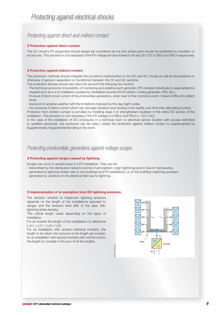
Implementation of or exemption from DC lightning arresters.
The decision whether to implement lightning arresters depends on the length of the installations exposed to danger and the keraunic level (Nk) of the area. (Nk: lightning strike density).This critical length varies depending on the types of installation. For an inverter the length of the installations to determineL is L = Lc1 + Lc2 + Lc3.For an installation with several individual inverters, the length to be taken into account is the length per inverter; for an installation with several inverters with central control, the length to consider is the sum of all the lengths.
cate
c-pv
024
a g
b InverterPath
LC2 LC3
LC1
AC
JB
10 SOCOMEC 2011 photovoltaic technical catalogue
Protecting photovoltaic generators
SOCOMEC 2011 photovoltaic technical catalogue
Protecting photovoltaic generators
The table below sets out exemptions from lightning conductors.This approach, based on a risk analysis, does not limit the implementation of protection devices should the protection value become inadequate compared with the value of the installation (P > ten or so kW).
Function Domestic Ground installation Large roofsCritical L. (ml) 1150 / Nk 2000 / Nk 4500 / NkL ≥ crit L. Lightning arrester compulsoryL < crit L. Lightning arrester not compulsoryLightning conductor present Lightning arrester compulsory
ExampleCrit. L. in Strasbourg: domestic= 57.5 - ground installation = 100 - large roofs = 225.
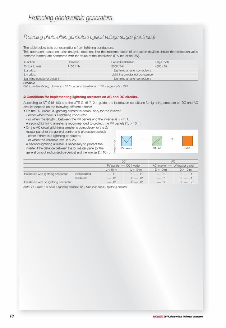
According to NT C15-100 and the UTE C 15-712-1 guide, the installation conditions for lightning arresters on DC and AC circuits depend on the following different criteria:• On the DC circuit, a lightning arrester is compulsory for the inverter:
- either when there is a lightning conductor, - or when the length L between the PV panels and the inverter is > crit. L.A second lightning arrester is recommended to protect the PV panels if L > 10 m.
• On the AC circuit a lightning arrester is compulsory for the LV master panel (or the general control and protection device):- either if there is a lightning conductor,- or when the keraunic level is > 25.A second lightning arrester is necessary to protect the inverter if the distance between the LV master panel (or the general control and protection device) and the inverter D > 10 m.
DC ACPV panels - DC inverter AC inverter - LV master panel
L < 10 m L > 10 m D < 10 m D > 10 mInstallation with lightning conductor Non isolated - T1 T1 - T1 - T1 T2 - T1
Insulated - T2 T2 - T2 - T1 T2 - T1Installation with no lightning conductor - T2 T2 - T2 - T2 T2 - T2
Note: T1 = type 1 or class 1 lightning arrester, T2 = type 2 or class 2 lightning arrester.
Protecting photovoltaic generators against voltage surges (continued)
cate
c-pv
044
b g
b
PV panels
L D
DC - AC LVSB
Conditions for implementing lightning arresters on AC and DC circuits..
11SOCOMEC 2011 photovoltaic technical catalogue 11SOCOMEC 2011 photovoltaic technical catalogue
Protecting photovoltaic generators
Current surges on photovoltaic generators
Shade on the generator
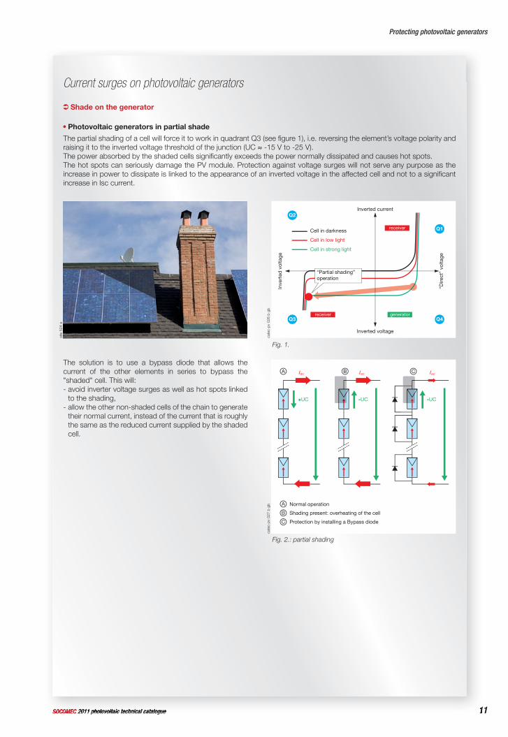
Photovoltaic generators in partial shade
The partial shading of a cell will force it to work in quadrant Q3 (see fi gure 1), i.e. reversing the element’s voltage polarity and raising it to the inverted voltage threshold of the junction (UC ≈ -15 V to -25 V).The power absorbed by the shaded cells signifi cantly exceeds the power normally dissipated and causes hot spots.The hot spots can seriously damage the PV module. Protection against voltage surges will not serve any purpose as the increase in power to dissipate is linked to the appearance of an inverted voltage in the affected cell and not to a signifi cant increase in Isc current.
The solution is to use a bypass diode that allows the current of the other elements in series to bypass the "shaded" cell. This will:- avoid inverter voltage surges as well as hot spots linked
to the shading,- allow the other non-shaded cells of the chain to generate
their normal current, instead of the current that is roughly the same as the reduced current supplied by the shaded cell.
site
524
a
cate
c-pv
026
b g
b
Inverted current
Cell in darkness
Cell in low light
Cell in strong light
receiver
receiver generator
Inve
rted
vol
tage
Inverted voltage
“Dire
ct”
volta
ge
Q1
Q4
Q2
Q3
“Partial shading”operation
Fig. 1.
cate
c-pv
027
b g
b
ISC
+UC
A ISC
-UC
ISC
-UC
B C
A
B
C
Normal operation
Shading present: overheating of the cell
Protection by installing a Bypass diode
Fig. 2.: partial shading
12 SOCOMEC 2011 photovoltaic technical catalogue
Protecting photovoltaic generators
SOCOMEC 2011 photovoltaic technical catalogue
Protecting photovoltaic generators
Current surges on photovoltaic generators (continued)
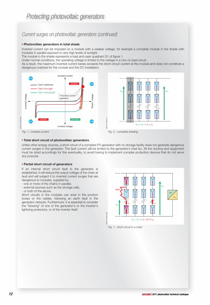
Photovoltaic generators in total shade
Inverted current can be imposed on a module with a weaker voltage, for example a complete module in the shade with modules in parallel exposed to very high levels of sunlight.The module in the shade represents a load and uses quadrant Q1 of fi gure 1. Under normal conditions, the operating voltage is limited to the voltage in a Uoc no load circuit. As a result, the maximum inverted current barely exceeds the short-circuit current at the module and does not constitute a dangerous overload for the module and the DC installation.
Total short circuit of photovoltaic generators
Unlike other energy sources, a short circuit of a complete PV generator with no storage facility does not generate dangerous current surges in the generator. The fault current will be limited to the generator’s total Isc. All the ducting and equipment must be sized accordingly for this eventuality, to avoid having to implement complex protection devices that do not serve any purpose.
Partial short circuit of generators
If an internal short circuit fault in the generator is established, it will reduce the output voltage of the chain at fault and will subject it to inverted current surges that are dangerous to modules, supplied by:- one or more of the chains in parallel,- external sources such as the storage cells,- or both of the above.Short circuits in the modules can arise in the junction boxes or the cables, following an earth fault in the generator network. Furthermore, it is essential to consider the "blowing" of one of the generator's or the inverter's lightning protectors, or of the inverter itself.
cate
c-pv
028
b g
b
cate
c-pv
029
a fr
Q1
Q4
Q2
Q3
“Inverted current”operation
Inverted current
Cell in darkness
Cell in low light
Cell in strong light
receiver
receiver generator
Inve
rted
vol
tage
Inverted voltage
“Dire
ct”
volta
ge
IR ISC
UC1
UC0 ≈ UC1 -> IR ≈ ISC
UC0
IRII
Fig. 2. : complete shading Fig. 1.: inverted current
cate
c-pv
030
a g
b
IR ISC
UC1
UC1 > UC2 -> IR = (n-1) ISC
UC2
fault
Fig. 1. : short circuit in a chain
13SOCOMEC 2011 photovoltaic technical catalogue 13SOCOMEC 2011 photovoltaic technical catalogue
Protecting photovoltaic generators
Current surges on photovoltaic generators (continued)
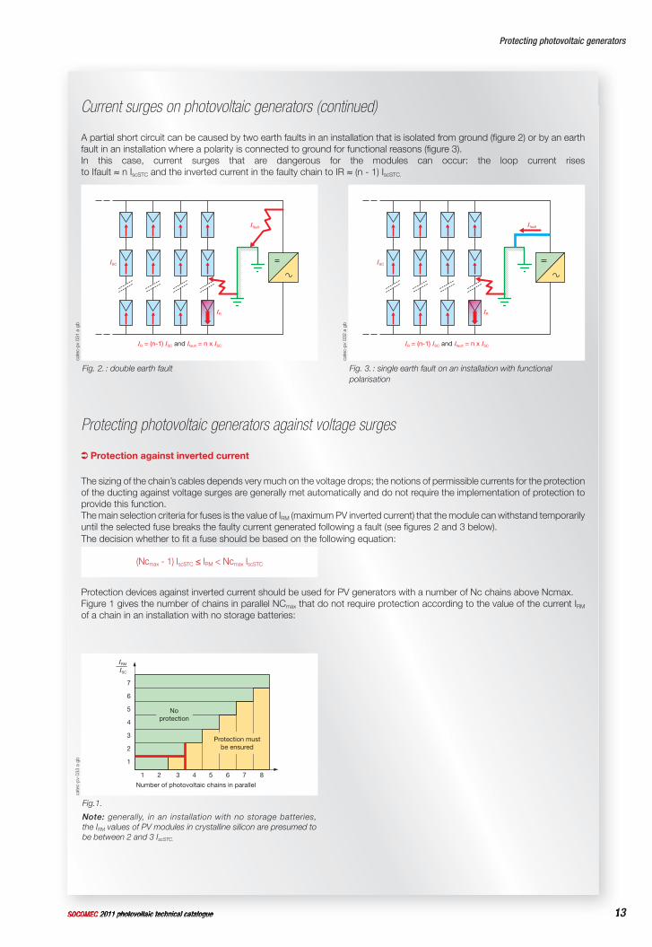
A partial short circuit can be caused by two earth faults in an installation that is isolated from ground (fi gure 2) or by an earth fault in an installation where a polarity is connected to ground for functional reasons (fi gure 3).In this case, current surges that are dangerous for the modules can occur: the loop current risesto Ifault ≈ n IscSTC and the inverted current in the faulty chain to IR ≈ (n - 1) IscSTC.
cate
c-pv
031
a g
bca
tec-
pv 0
33 a
gb
cate
c-pv
032
a g
b
IR
Ifault
ISC
IR = (n-1) ISC and Ifault = n x ISC
Number of photovoltaic chains in parallel
1 2 3 4 5 6 7 8
7
6
5
4
3
2
1
IRM
ISC
Noprotection
Noprotection
Protection mustbe ensured
Protection mustbe ensured
IR
Ifault
ISC
IR = (n-1) ISC and Ifault = n x ISC
Fig. 3. : single earth fault on an installation with functional polarisation
Fig. 2. : double earth fault
Fig. 1.
Note: generally, in an installation with no storage batteries,the IRM values of PV modules in crystalline silicon are presumed to be between 2 and 3 IscSTC.
Protecting photovoltaic generators against voltage surges
Protection against inverted current
The sizing of the chain’s cables depends very much on the voltage drops; the notions of permissible currents for the protection of the ducting against voltage surges are generally met automatically and do not require the implementation of protection to provide this function.The main selection criteria for fuses is the value of IRM (maximum PV inverted current) that the module can withstand temporarily until the selected fuse breaks the faulty current generated following a fault (see fi gures 2 and 3 below). The decision whether to fi t a fuse should be based on the following equation:
(Ncmax - 1) IscSTC ≤ IRM < Ncmax IscSTC
Protection devices against inverted current should be used for PV generators with a number of Nc chains above Ncmax.Figure 1 gives the number of chains in parallel NCmax that do not require protection according to the value of the current IRM of a chain in an installation with no storage batteries:

14 SOCOMEC 2011 photovoltaic technical catalogue
Protecting photovoltaic generators
SOCOMEC 2011 photovoltaic technical catalogue
Protecting photovoltaic generators
14
Protecting photovoltaic generators against voltage surges (continued)
The general rule is that each chain is protected individually by a protection device. In certain cases with modules having very high resistance to inverted current, Np chains can be connected in parallel to a single protection device.Np max : Maximum number of chains in parallel per protection deviceResistance of the module to inverted current Npmax1.4 IscSTC ≤ IRM < 3.8 IscSTC 13.8 IscSTC ≤ IRM < 6.2 IscSTC 26.2 IscSTC ≤ IRM < 8.6 IscSTC 3General case: (2.4 Npmax -1) IscSTC ≤ IRM < (2.4 Npmax +1.4) IscSTC
Information on the IRM given by manufacturers of photovoltaic modules
Certain manufacturers specify a max inverted current more or less equal to the nominal short circuit current and a signifi cantly higher fuse rating. Apparently, this low inverted current is supposed to defi ne defrosting currents or currents to remove a fi ne layer of snow, the fuse value therefore providing protection in fault conditions. When the manufacturer defi nes a max fuse rating, this information must be taken into consideration. However, should there be any doubt over the exact fuse type, this should be clarifi ed with the manufacturer‘s customer services department.
Protection against excessive sunlight exposure
Protection according to module resistance to inverted current (IRM)
The use of a fuse over its nominal rating should be avoided. This critical zone is the zone between the nominal current and the non-fusing current (Inf).This is particularly important for fuses subjected to cyclic temperature fl uctuations, typical of PV systems.The nominal current In of the chain’s PV fuse should be higher than the maximum operating current of the chain, which varies between 1.25 and 1.6 IscSTC depending on the climatic conditions and the sunlight levels. The PV fuses should not operate, or damage the installation in normal operating conditions in order to avoid operating losses. In order to meet this requirement, a fuse with a nominal current that is 40% higher than the Isc of the PV chain is selected.
According to standard IEC 61730, the IRM current, corresponds to a 2 hour test at 1.35 IRM; therefore, protection is ensured if the selected fuse operates correctly with the value of 1.35 IRM.The conventional If (or I2) disconnection time of a fuse is 1 hour, so greater than the 2 hours of the module, which provides a safety margin by giving a max fuse current for a specifi c module. The different conventional fusing times and currents for the various types of fuses available should be checked against these coordination rules:In ≤ 0.85 IRM for gR, gS or gG fuses ≥ 16 A In ≤ 0.7 IRM for gG fuses < 16 A "gPV" fuses that are compliant with the forthcoming standard IEC 60 269-6, provide PV protection, If =1.45 In and can be selected at In ≤ IRM.
cate
c-pv
034
b g
b
Operating zone of the fuse
Modules
Inf If
0 0.5 1 1.5 2 2.5 3
Fuses
I/IscSTC
IRM
In
PV modules
gPV fuses
Inf: fusing current of the fuses
If or I2: maximum fusing current of the fuses
In ≥ 1.4 IscSTC
cate
c-pv
035
b g
b
0.4 0.6 0.8 1 1.20 1.35 de IRM
Modules
Inf If
Fuses
Iscr
In
gPV fuses
2h performance
Operating zone of the fuse
Inf: fusing current of the fuses
If or I2: maximum fusing current of the fuses
If ≤ 1.35 IRM or In ≤ IRM
15SOCOMEC 2011 photovoltaic technical catalogue 15SOCOMEC 2011 photovoltaic technical catalogue
Protecting photovoltaic generators
Protecting photovoltaic generators against voltage surges (continued)
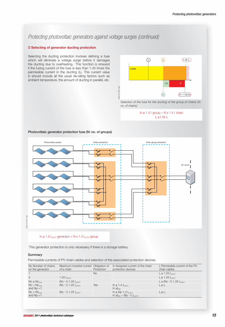
Selecting of generator ducting protection
Selecting the ducting protection involves defi ning a fuse which will eliminate a voltage surge before it damages the ducting due to overheating.. This function is ensured if the fusing current of the fuse is less than 1.45 times the permissible current in the ducting (Iz). This current value Iz should include all the usual de-rating factors such as ambient temperature, the amount of ducting in parallel, etc.
cate
c-pv
036
a g
b
Inf If
Cable
In
Ic Iz 1.45 Iz
If = 1.45 In
Selection of the fuse for the ducting of the group of chains (N : no. of chains)
In ≥ 1.4 I group = N x 1.4 I chainI2 ≥1.45 Iz
Photovoltaic generator protection fuse (N: no. of groups)
cate
c-pv
037
b g
b
Chain protection Chain group protectionPhotovoltaic panels
DC circuit
In ≥ 1.4 IscSTC generator = N x 1.4 IscSTC group
This generator protection is only necessary if there is a storage battery.
Summary
Permissible currents of PV chain cables and selection of the associated protection devices.
Nc Number of chainson the generator
Maximum inverted current of a chain
Obligation of Protection
In Assigned current of the chain protection devices
Iz Permissible current of the PV chain cables
1 - No Iz ≥ 1.25 IscSTC
2 1.25 IscSTC Iz ≥ 1.25 IscSTC
Nc ≤ Ncmax (Nc -1) 1.25 IscSTC Iz ≥ (Nc -1) 1.25 IscSTC
Nc > Ncmax
and Np =1(Nc -1) 1.25 IscSTC Yes In ≥ 1.4 IscSTC
In ≤IRM
Iz ≥ I2
Nc > Ncmax
and Np =1(Nc -1) 1.25 IscSTC In ≥ Np 1.4 IscSTC
In ≤IRM – (Np -1) IscSTC
Iz ≥ I2
16 SOCOMEC 2011 photovoltaic technical catalogue
Protecting photovoltaic generators
SOCOMEC 2011 photovoltaic technical catalogue
Protecting photovoltaic generators
Protecting photovoltaic generators against voltage surges (continued)
Disconnection power of the photovoltaic fuses
The chain’s PV fuses should have a disconnection power greater than or equal to the maximum fault current of the PV system. A value of 25 kA DC is recommended to include any possible provisions for energy storage or possible returns of energy on the distribution network. The time constant of a PV circuit is generally less than 2 ms (L/R), the PV fuses accept much higher time constants.
Type of fuses to use
The PV fuses must be selected with a type "g" general usage curve, as they will safely disconnect all the current ranges, from the minimum fusing value to the maximum disconnection power. "a" series fuses (supplementary type) are totally inappropriate and must not be used under any circumstances, as they risk failing to manage arcs above their minimum disconnection power.The use of inappropriate fuses in a PV installation can cause much more disarray than the required protection level.
Photovoltaic fuse operating voltage
To include the infl uence of the temperature in "cold" conditions, it is recommended to increase the operating voltage of the fuse to be fi tted by 20 %.
Un ≥ UocSTC x 1.2
UocSTC : voltage in open circuit of the PV chainNote: the coefficient 1.2 allows variations in voltage UocSTC to be included according to low temperatures down to -25 °C for mono or polycrystalline panels. This coefficient can be adapted for installations when the minimum temperatures are different.
Thermal de-rating
Although PV fuses dissipate relatively little heat, the internal temperatures of the junction boxes protecting the chains should be taken into account because of the exposure to high ambient temperatures and the large amount of equipment such as blocking diodes or other monitoring equipment.The rated diversity factors (RDF) specifi ed by standard IEC 61 439 are not applicable, as it is necessary to take into account all the circuits at their maximum load and at the same time (diversity factor =1).The derating factors at temperatures recommended by the fuse manufacturer should be applied.
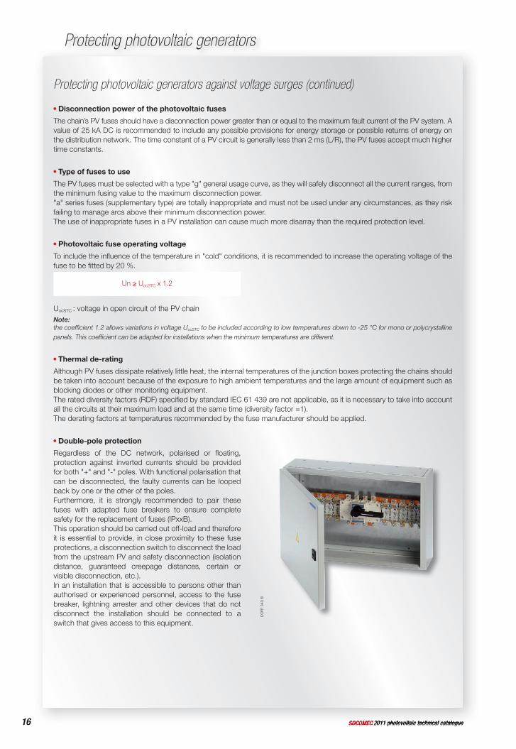
Double-pole protection
Regardless of the DC network, polarised or fl oating, protection against inverted currents should be provided for both "+" and "-" poles. With functional polarisation that can be disconnected, the faulty currents can be looped back by one or the other of the poles.Furthermore, it is strongly recommended to pair these fuses with adapted fuse breakers to ensure complete safety for the replacement of fuses (IPxxB). This operation should be carried out off-load and therefore it is essential to provide, in close proximity to these fuse protections, a disconnection switch to disconnect the load from the upstream PV and safety disconnection (isolation distance, guaranteed creepage distances, certain or visible disconnection, etc.).In an installation that is accessible to persons other than authorised or experienced personnel, access to the fuse breaker, lightning arrester and other devices that do not disconnect the installation should be connected to a switch that gives access to this equipment.
CO
FF 3
43 B
17SOCOMEC 2011 photovoltaic technical catalogue 17SOCOMEC 2011 photovoltaic technical catalogue
Protecting photovoltaic generators
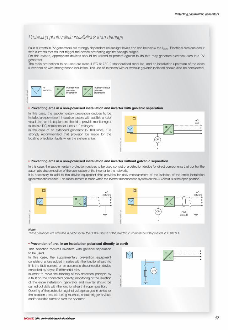
Preventing arcs in a non-polarised installation and inverter with galvanic separation
In this case, the supplementary prevention devices to be installed are permanent insulation testers with audible and/or visual alarms; this equipment should to provide monitoring of faults in a DC installation for Uoc x 1.2 voltages.In the case of an extended generator (> 100 kWc), it is strongly recommended that provision be made for the locating of isolation faults when the system is live.
Preventing arcs in a non-polarised installation and inverter without galvanic separation
In this case, the supplementary protection devices to be used consist of a detection device for direct components that control the automatic disconnection of the connection of the inverter to the network. It is necessary to add to this device equipment that provides for daily measurement of the isolation of the entire installation (generator and inverter). This measurement is taken when the inverter disconnection system on the AC circuit is in the open position.
Note: These provisions are provided in particular by the RCMU device of the inverters in compliance with prenorm VDE 0126-1.
Prevention of arcs in an installation polarised directly to earth
This selection requires inverters with galvanic separation to be used.In this case, the supplementary prevention equipment consists of a fuse added in series with the functional earth to limit the fault current, or an automatic disconnection device controlled by a type B differential relay.In order to avoid the blinding of this detection principle by a fault on the connected polarity, monitoring of the isolation of the entire installation, generator and inverter should be carried out daily with the functional earth in open position. Opening of the protection against voltage surges in series, or the isolation threshold being reached, should trigger a visual and/or audible alarm to alert the operator.
Protecting photovoltaic installations from damage
Fault currents in PV generators are strongly dependent on sunlight levels and can be below the IscSTC. Electrical arcs can occur with currents that will not trigger the device protecting against voltage surges. For this reason, appropriate devices should be utilised to protect against faults that may generate electrical arcs in a PV generator. The main protections to be used are class II IEC 61730-2 standardised modules, and an installation upstream of the class II inverters or with strengthened insulation. The use of inverters with or without galvanic isolation should also be considered.
cate
c-pv
038
a g
b
Inverter withoutgalvanicseparation
Inverter withgalvanicseparation
PVmodules
cate
c-pv
039
a g
b CPI
ACuse
cate
c-pv
040
a g
b
ACnetwork
RC
MU
cate
c-pv
041
a g
b
ACnetwork
DDRclass B
CPI
cate
c-pv
042
a fr
CPI
18 SOCOMEC 2011 photovoltaic technical catalogue
Protecting photovoltaic generators
SOCOMEC 2011 photovoltaic technical catalogue
Protecting photovoltaic generators
Preventing photovoltaic installations from damage (continued)
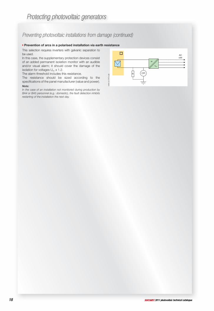
Prevention of arcs in a polarised installation via earth resistance
This selection requires inverters with galvanic separation to be used.In this case, the supplementary protection devices consist of an added permanent isolation monitor with an audible and/or visual alarm; it should cover the damage of the isolation for voltages Uoc x 1.2.The alarm threshold includes this resistance.The resistance should be sized according to the specifi cations of the panel manufacturer (value and power).Note:In the case of an installation not monitored during production by BA4 or BA5 personnel (e.g.: domestic), the fault detection inhibits restarting of the installation the next day.
cate
c-pv
043
a g
b CPI
ACuse
R
19SOCOMEC 2011 photovoltaic technical catalogue 19SOCOMEC 2011 photovoltaic technical catalogue
PV cell
Fundamental PV device able to generate electricity when it is exposed to light such as sunlight.
PV module
The smallest component of interconnected solar cells completely protected against the environment.
PV chain
Circuit where the PV modules are connected in series to form assemblies, in order to generate the specifi ed output voltage.
PV group
Integrated mechanical and electrical assembly of chains and other components to make up a DC electrical current production unit.
PV group junction box
Enclosure inside which all the PV chains of all the PV groups are electrically connected and where any protection devices can be placed.
PV generator
Assembly of PV generators, also called PV fi eld.
PV conversion equipment
Device that transforms DC voltage into AC voltage, also called an inverter.
Standard test conditions (STC)
Test conditions prescribed in NF EN 60904-3 (C 57-323) for PV cells and modules.
Open circuit voltage UocSTC
Voltage in standardised test conditions, at the terminals of a PV module, a PV chain, a non-charged PV group (open) or at the terminals of the DC circuit of the PV conversion equipment.
Short circuit current IscSTC
Short circuit current of a module, a chain, a PV group or a PV generator under standardised test conditions.
Maximum inverted current IRM
Maximum value of inverted current which a module can withstand without any damage. This value is supplied by the manufacturer.Note 1: This value does not concern the current withstood by the diverting diodes, but the current going through the PV cells in the inverted direction of the normal current.Note 2: The typical value for crystalline silicon is between 2 and 2.6 IscSTC of the module.
Maximum Power Point (MPP or MPPT)
This principle, as indicated by its name (Maximum Power Point Tracker), makes it possible to track the maximum power point of a non-linear electrical generator such as a photovoltaic generator. The MPPT or MPPTs also generally represent a component of the inverter allowing optimised use of solar radiation, by adapting its load to the characteristics of the PV generator according to the actual sunlight.
Glossary of common photovoltaic terms
Ref
. DC
G 1
0802
3 - 0
3/11
Ph
oto:
Mar
tin B
ernh
art -
Pro
duct
ion:
SO
CO
MEC
Com
mun
icat
ions
& P
ublic
atio
ns S
ervi
ceC
OU
V 18
0 A
/ QU
AT S
CP
1
Socomec worldwide
Non contractual document. © 2010, Socomec SA. All rights reserved.
w w w. s o c o m e c . c o m
VALID FOR FRANCE
Ref
. DC
G 1
0802
3 - 0
3/11
Ph
oto:
Mar
tin B
ernh
art -
Pro
duct
ion:
SO
CO
MEC
Com
mun
icat
ions
& P
ublic
atio
ns S
ervi
ce
Non contractual document. © 2010, Socomec SA. All rights reserved.
H E A D O F F I C ESOCOMEC GROUP S.A. SOCOMEC capital 11 303 400 R.C.S. Strasbourg B 548 500 149B.P. 60010 - 1, rue de Westhouse F-67235 Benfeld Cedex - FRANCE
I N T E R N AT I O N A L S A L E S D E P A R T M E N TSOCOMEC 1, rue de Westhouse - B.P. 60010F - 67235 Benfeld Cedex - FRANCETel. +33 (0)3 88 57 41 41 - Fax +33 (0)3 88 74 08 [email protected]
I N E U R O P E
BELGIUM SOCOMEC BELGIUMB - 1190 BrusselTel. +32 (0)2 340 02 30 - Fax +32 (0)2 346 28 [email protected]
FRANCE SOCOMECF - 94132 Fontenay-sous-Bois CedexTel. +33 (0)1 45 14 63 30 - Fax +33 (0)1 45 14 63 [email protected]
GERMANY SOCOMEC GmbHD - 76275 EttlingenTel. +49 (0)7243 65 29 2 0 - Fax +49 (0)7243 65 29 2 [email protected]
ITALY SOCOMEC Elettrotecnica s.r.l.I - 20098 San Giuliano Milanese (MI)Tel. +39 02 9849821 - Fax +39 02 [email protected]
SPAIN SOCOMEC ELECTRO, S.L.E - 08310 Argentona (Barcelona) Tel. +34 93 741 60 67 - Fax. +34 93 757 49 [email protected]
THE NETHERLANDS SOCOMEC B.V.NL - 3992 De HoutenTel. +31 (0)30 63 71 504 - Fax +31 (0)30 63 72 [email protected]
THE UNITED KINGDOM SOCOMEC LtdHitchin Hertfordshire SG4 0TYTel. +44 (0)1462 440033 - Fax +44 (0)1462 [email protected]
CO
UV
180
A / Q
UAT
SC
P 1
I N A S I A
NORTH EAST ASIA SOCOMEC CHINACN - 200030 P.R.C Shanghai - ChinaTel. +86 (0)21 5298 9555 - Fax +86 (0)21 6228 [email protected]
SOUTH EAST ASIA & PACIFIC SOCOMEC SWITCHING AND PROTECTIONUBI TECHPARK - 408569 SingaporeTel. +65 65 07 94 90 - Fax +65 65 47 86 [email protected]
SOUTH ASIASOCOMEC INDIA122001 Gurgaon, Haryana - IndiaTel. +91 124 4562 700 - Fax +91 124 4562 [email protected]
Ref
. DC
G 1
0802
3 - 0
3/11
Ph
oto:
Mar
tin B
ernh
art -
Pro
duct
ion:
SO
CO
MEC
Com
mun
icat
ions
& P
ublic
atio
ns S
ervi
ce I N M I D D L E E A S T
UNITED ARAB EMIRATES SOCOMEC Middle EastDubai, U.A.E. Tel. +971 (0) 4 29 98 441 - Fax +971 (0)4 29 98 [email protected]
Ref
. DC
G 1
0802
3 - 0
3/11
Ph
oto:
Mar
tin B
ernh
art -
Pro
duct
ion:
SO
CO
MEC
Com
mun
icat
ions
& P
ublic
atio
ns S
ervi
ce
I N N O R T H A M E R I C A
USA, CANADA & MEXICOSOCOMEC IncCambridge, MA 02142 USATel. +1 617 245 0447 - Fax +1 617 245 [email protected]