00 - ii technical spec cover
TRANSCRIPT

TECHNICAL SPECIFICATIONS
FOR THE
SIERRA COUNTY WELLNESS CENTER ADDITION PROJECT
WELLNESS CENTER207 FRONT STEEET
LOYALTON, CALIFORNIA 96118
PREPARED BY
Bruce E. Boyd Architects & Planners 17894 Tyler Foote Road
Nevada City California 95959 530 – 265 – 5280 [email protected]
October 10, 2018

SIERRA COUNTY WELLNESS CENTER CONTRACT DOCUMENTS TABLE OF CONTENTS
011000 - SUMMARY
012500 - SUBSTITUTION PROCEDURES 012600 - CONTRACT MODIFICATION PROCEDURES 013100 - PROJECT MANAGEMENT AND COORDINATION
013300 - SUBMITTAL PROCEDURES 015000 - TEMPORARY FACILITIES AND CONTROLS 017300 - EXECUTION 017700 - CLOSEOUT PROCEDURES
017823 - OPERATION AND MAINTENANCE DATA 017839 - PROJECT RECORD DOCUMENTS 024119 - SELECTIVE DEMOLITION
033000 - CAST-IN-PLACE CONCRETE 055213 - PIPE AND TUBE RAILINGS 062013 - EXTERIOR FINISH CARPENTRY 062023 - INTERIOR FINISH CARPENTR
064116 - PLASTIC-LAMINATE-FACED ARCHITECTURAL CABINETS 070150 - PREPARATION FOR RE-ROOFING 072100 - THERMAL INSULATION
073113 - ASPHALT SHINGLES 076200 - SHEET METAL FLASHING AND TRIM 074646 - FIBER-CEMENT SIDING 081433 - STILE AND RAIL WOOD DOORS
081436 - HINGED WOOD-FRAMED GLASS DOORS 085313 - VINYL WINDOWS 087100 - DOOR HARDWARE
096513 - RESILIENT BASE AND ACCESSORIES 096516 - RESILIENT SHEET FLOORING 096816 - SHEET CARPETING 092900 - GYPSUM BOARD
099113 - EXTERIOR PAINTING 099123 - INTERIOR PAINTING 102116 - PLASTIC SHOWER AND DRESSING COMPARTMENTS
102800 - TOILET, BATH, AND LAUNDRY ACCESSORIES 104416 - FIRE EXTINGUISHERS 122413 - ROLLER WINDOW SHADES 123623 - PLASTIC-LAMINATE-CLAD COUNTERTOPS
TABLE OF CONTENTS 10/10/18

SIERRA COUNTY WELLNESS CENTER CONTRACT DOCUMENTS TABLE OF CONTENTS
160100 - ELECTRICAL GENERAL PROVISIONS
221313 - FACILITY SANITARY SEWERS 224100 - RESIDENTIAL PLUMBING FIXTURES 312000 - EARTH MOVING
321313 - CONCRETE PAVING 330500 - COMMON WORK RESULTS FOR UTILITIES
TABLE OF CONTENTS 10/10/18

SIERRA COUNTY WELLNESS CENTER CONTRACT DOCUMENTS 10/10/18
SECTION 011000 - SUMMARY
1.GENERAL
1. SUMMARY
A. Section Includes:
1. Project information. 2. Work covered by Contract Documents. 3. Phased construction. 4. Work under separate contracts. 5. Access to site. 6. Coordination with occupants. 7. Work restrictions. 8. Specification and drawing conventions. 9. Miscellaneous provisions.
B. Related Requirements:
1. Section 015000 "Temporary Facilities and Controls" for limitations and procedures governing temporary use of Owner's facilities.
2. PROJECT INFORMATION
A. Project Identification: Sierra County Wellness Center Addition Project
B. Project Location: 207 Front Street Loyalton California 95936.
C. Owner: Sierra County Department of Health.
1. Owner's Representative: Tim Beals, Director of Public Works, 101 Courthouse Square Downieville CA 95936
2. Architect: Bruce E. Boyd, 17894 Tyler Foote Road, Nevada City, CA, 95959.
3. WORK COVERED BY CONTRACT DOCUMENTS
A. The Work of Project is defined by the Contract Documents and consists of the following:
1. Work consists of the complete construction of an office addition and interior remodeling of an existing facility. Work includes but is not limited to foundations, framing, roofing, siding, interior finishes, mechanical work, plumbing and electrical work.
B. Type of Contract.
1. Project will be constructed under a single prime contract.
a. County of Sierra Public Works Contract Short form
SUMMARY 011000 - ! 1

SIERRA COUNTY WELLNESS CENTER CONTRACT DOCUMENTS 10/10/18
4. ACCESS TO SITE
A. General: Contractor shall have full use of Project site for construction operations during construction period. Contractor's use of Project site is limited only by Owner's right to perform work or to retain other contractors on portions of Project.
B. General: Contractor shall have limited use of Project site for construction operations as indicated on Drawings by the Contract limits and as indicated by requirements of this Section.
C. Use of Site: Limit use of Project site to work in areas indicated. Do not disturb portions of Project site beyond areas in which the Work is indicated.
1. Limits: Confine construction operations to the parcel shown on the drawings. 2. Limits: Limit site disturbance, including earthwork and clearing of vegetation, to within
5’ of all property lines. 10 feet beyond surface walkways, surface parking, and utilities . 3. Driveways, Walkways and Entrances: loading areas and entrances serving premises clear
and available to Owner, Owner's employees, and emergency vehicles at all times. Do not use these areas for parking or storage of materials.
a. Schedule deliveries to minimize use of entrances by construction operations. b. Schedule deliveries to minimize space and time requirements for storage of
materials and equipment on-site.
D. Condition of Existing Building: Maintain portions of existing building affected by construction operations in a weathertight condition throughout construction period. Repair damage caused by construction operations.
5. COORDINATION WITH OCCUPANTS
A. Owner Limited Occupancy of Completed Areas of Construction: Owner reserves the right to occupy and to place and install equipment in completed portions of the Work, prior to Substantial Completion of the Work, provided such occupancy does not interfere with completion of the Work. Such placement of equipment and limited occupancy shall not constitute acceptance of the total Work. 1. Obtain a Certificate of Occupancy from authorities having jurisdiction before limited
Owner occupancy. 2. Before limited Owner occupancy, mechanical and electrical systems shall be fully
operational, and required tests and inspections shall be successfully completed. On occupancy, Owner will operate and maintain mechanical and electrical systems serving occupied portions of Work.
3. On occupancy, Owner will assume responsibility for maintenance and custodial service for occupied portions of Work.
6. WORK RESTRICTIONS
A. Work Restrictions, General: Comply with restrictions on construction operations.
1. Comply with limitations on use of public streets and with other requirements of authorities having jurisdiction.
B. On-Site Work Hours: Limit work in the existing building to normal business working hours of 7:00 a.m. to 6:00 p.m., Monday through Friday, unless otherwise indicated.
SUMMARY 011000 - ! 2

SIERRA COUNTY WELLNESS CENTER CONTRACT DOCUMENTS 10/10/18
C. Existing Utility Interruptions: Do not interrupt utilities serving facilities occupied by Owner or others unless permitted under the following conditions and then only after providing temporary utility services according to requirements indicated:
1. Notify not less than two days in advance of proposed utility interruptions.
D. Noise, Vibration, and Odors: Coordinate operations that may result in high levels of noise and vibration, odors, or other disruption to Owner occupancy with Owner.
E. Nonsmoking Building: Smoking is not permitted within the building or within 50 feet (8 m) of entrances, operable windows, or outdoor-air intakes.
F. Controlled Substances: Use of tobacco products and other controlled substances within the existing building and on Project site is not permitted.
END OF SECTION 011000
SUMMARY 011000 - ! 3

SIERRA COUNTY WELLNESS CENTER CONTRACT DOCUMENTS 10/10/18
SECTION 012500 - SUBSTITUTION PROCEDURES
1.GENERAL
1. SUMMARY
A. Section includes administrative and procedural requirements for substitutions.
2. DEFINITIONS
A. Substitutions: Changes in products, materials, equipment, and methods of construction from those required by the Contract Documents and proposed by Contractor.
3. ACTION SUBMITTALS
A. Substitution Requests: Submit three copies of each request for consideration. Identify product or fabrication or installation method to be replaced. Include Specification Section number and title and Drawing numbers and titles. 1. Documentation: Show compliance with requirements for substitutions and the following,
as applicable:
a. Statement indicating why specified product or fabrication or installation cannot be provided, if applicable.
b. Product Data, including drawings and descriptions of products and fabrication and installation procedures.
c. Samples, where applicable or requested.
2. Architect's Action: If necessary, Architect will request additional information or documentation for evaluation within seven days of receipt of a request for substitution. Architect will notify Contractor of acceptance or rejection of proposed substitution within 10 days of receipt of request, or 7 days of receipt of additional information or documentation, whichever is later.
a. Forms of Acceptance: Change Order, Construction Change Directive, or Architect's Supplemental Instructions for minor changes in the Work.
b. Use product specified if Architect does not issue a decision on use of a proposed substitution within time allocated.
2.PRODUCTS
1. SUBSTITUTIONS
A. Substitutions for Cause: Submit requests for substitution immediately on discovery of need for change, but not later than 15 days prior to time required for preparation and review of related submittals.
SUBSTITUTION PROCEDURES 012500 - ! 1
SIERRA COUNTY WELLNESS CENTER CONTRACT DOCUMENTS 10/10/18
1. Conditions: Architect will consider Contractor's request for substitution when the following conditions are satisfied:
a. Requested substitution is consistent with the Contract Documents and will produce indicated results.
b. Requested substitution will not adversely affect Contractor's construction schedule. c. Requested substitution has received necessary approvals of authorities having
jurisdiction. d. Requested substitution is compatible with other portions of the Work. e. Requested substitution has been coordinated with other portions of the Work. f. Requested substitution provides specified warranty. g. If requested substitution involves more than one contractor, requested substitution
has been coordinated with other portions of the Work, is uniform and consistent, is compatible with other products, and is acceptable to all contractors involved.
B. Substitutions for Convenience: Not allowed.
3.EXECUTION (Not Used)
END OF SECTION 012500
SUBSTITUTION PROCEDURES 012500 - ! 2

SIERRA COUNTY WELLNESS CENTER CONTRACT DOCUMENTS 10/10/18
SECTION 012600 - CONTRACT MODIFICATION PROCEDURES
1.GENERAL
1. SUMMARY
A. Section includes administrative and procedural requirements for handling and processing Contract modifications.
2. MINOR CHANGES IN THE WORK
A. Architect will issue through Construction Manager supplemental instructions authorizing minor changes in the Work, not involving adjustment to the Contract Sum or the Contract Time, on AIA Document G710, "Architect's Supplemental Instructions.”
B. PROPOSAL REQUESTS
C. Owner-Initiated Proposal Requests: Architect will issue a detailed description of proposed changes in the Work that may require adjustment to the Contract Sum or the Contract Time. If necessary, the description will include supplemental or revised Drawings and Specifications.
1. Work Change Proposal Requests issued by Architect are not instructions either to stop work in progress or to execute the proposed change.
2. Within time specified in Proposal Request or 20 days, when not otherwise specified, after receipt of Proposal Request, submit a quotation estimating cost adjustments to the Contract Sum and the Contract Time necessary to execute the change.
a. Include a list of quantities of products required or eliminated and unit costs, with total amount of purchases and credits to be made. If requested, furnish survey data to substantiate quantities.
b. Indicate applicable taxes, delivery charges, equipment rental, and amounts of trade discounts.
c. Include costs of labor and supervision directly attributable to the change. d. Include an updated Contractor's construction schedule that indicates the effect of
the change, including, but not limited to, changes in activity duration, start and finish times, and activity relationship. Use available total float before requesting an extension of the Contract Time.
e. Quotation Form: Use forms acceptable to Architect.
D. Contractor-Initiated Work Change Proposals: If latent or changed conditions require modifications to the Contract, Contractor may initiate a claim by submitting a request for a change to Architect.
1. Include a statement outlining reasons for the change and the effect of the change on the Work. Provide a complete description of the proposed change. Indicate the effect of the proposed change on the Contract Sum and the Contract Time.
2. Include a list of quantities of products required or eliminated and unit costs, with total amount of purchases and credits to be made. If requested, furnish survey data to substantiate quantities.
3. Indicate applicable taxes, delivery charges, equipment rental, and amounts of trade discounts.
CONTRACT MODIFICATION PROCEDURES 012600 - ! 1

SIERRA COUNTY WELLNESS CENTER CONTRACT DOCUMENTS 10/10/18
4. Include costs of labor and supervision directly attributable to the change. 5. Include an updated Contractor's construction schedule that indicates the effect of the
change, including, but not limited to, changes in activity duration, start and finish times, and activity relationship. Use available total float before requesting an extension of the Contract Time.
6. Comply with requirements in Section 012500 "Substitution Procedures" if the proposed change requires substitution of one product or system for product or system specified.
7. Work Change Proposal Request Form: Use A form acceptable to Architect.
3. CHANGE ORDER PROCEDURES
A. On Owner's approval of a Work Changes Proposal Request, Architect will issue a Change Order for signatures of Owner and Contractor on AIA Document G701
B. CONSTRUCTION CHANGE DIRECTIVE
C. Construction Change Directive: Architect may issue a Construction Change Directive on AIA Document G714. Construction Change Directive instructs Contractor to proceed with a change in the Work, for subsequent inclusion in a Change Order.
1. Construction Change Directive contains a complete description of change in the Work. It also designates method to be followed to determine change in the Contract Sum or the Contract Time.
D. Documentation: Maintain detailed records on a time and material basis of work required by the Construction Change Directive.
1. After completion of change, submit an itemized account and supporting data necessary to substantiate cost and time adjustments to the Contract.
2.PRODUCTS (Not Used)
3.EXECUTION (Not Used)
END OF SECTION 012600
CONTRACT MODIFICATION PROCEDURES 012600 - ! 2

SIERRA COUNTY WELLNESS CENTER CONTRACT DOCUMENTS 10/10/18
SECTION 013100 - PROJECT MANAGEMENT AND COORDINATION
1.GENERAL
1. SUMMARY
A. Section includes administrative provisions for coordinating construction operations on Project including, but not limited to, the following:
1. Coordination drawings. 2. Requests for Information (RFIs). 3. Project meetings.
2. DEFINITIONS
A. RFI: Request from Owner, Architect, or Contractor seeking information required by or clarifications of the Contract Documents.
3. INFORMATIONAL SUBMITTALS
A. Subcontract List: Prepare a written summary identifying individuals or firms proposed for each portion of the Work, including those who are to furnish products or equipment fabricated to a special design. Include the following information in tabular form:
1. Name, address, and telephone number of entity performing subcontract or supplying products.
4. GENERAL COORDINATION PROCEDURES
A. Coordination: Coordinate construction operations included in different Sections of the Specifications to ensure efficient and orderly installation of each part of the Work. Coordinate construction operations, included in different Sections, that depend on each other for proper installation, connection, and operation.
5. REQUESTS FOR INFORMATION (RFIs)
A. General: Immediately on discovery of the need for additional information or interpretation of the Contract Documents, Contractor shall prepare and submit an RFI in the form specified.
1. Architect will return RFIs submitted to Architect by other entities controlled by Contractor with no response.
2. Coordinate and submit RFIs in a prompt manner so as to avoid delays in Contractor's work or work of subcontractors.
B. Architect’s Action: Architect will review each RFI, determine action required, and respond. Allow 7 working days for Architect's response for each RFI. RFIs received by Architect after 1:00 p.m. will be considered as received the following working day.
PROJECT MANAGEMENT AND COORDINATION 013100 - ! 1
SIERRA COUNTY WELLNESS CENTER CONTRACT DOCUMENTS 10/10/18
C. RFI Log: Prepare, maintain, and submit a tabular log of RFIs organized by the RFI number. Submit log monthly. Use software log with not less than the following:
1. Project name. 2. Name and address of Contractor. 3. Name and address of Architect. 4. RFI number including RFIs that were dropped and not submitted. 5. RFI description. 6. Date the RFI was submitted. 7. Date Architect's response was received.
D. On receipt of Architect's action, update the RFI log and immediately distribute the RFI response to affected parties. Review response and notify Architect within 7 days if Contractor disagrees with response.
1. Identification of related Minor Change in the Work, Construction Change Directive, and Proposal Request, as appropriate.
2. Identification of related Field Order, Work Change Directive, and Proposal Request, as appropriate.
6. PROJECT MEETINGS
A. General: Schedule and conduct meetings and conferences at Project site unless otherwise indicated.
1. Attendees: Inform participants and others involved, and individuals whose presence is required, of date and time of each meeting. Notify Owner and Architect of scheduled meeting dates and times.
2. Agenda: Prepare the meeting agenda. Distribute the agenda to all invited attendees. 3. Minutes: Entity responsible for conducting meeting will record significant discussions
and agreements achieved. Distribute the meeting minutes to everyone concerned, including Owner, and Architect, within 4 days of the meeting.
B. Preconstruction Conference: Architect will schedule and conduct a preconstruction conference before starting construction, at a time convenient to Owner and Architect, but no later than 15 days after execution of the Agreement.
C. Progress Meetings: Conduct progress meetings at biweekly intervals.
2.PRODUCTS (Not Used)
3.EXECUTION (Not Used)
END OF SECTION 013100
PROJECT MANAGEMENT AND COORDINATION 013100 - ! 2

SIERRA COUNTY WELLNESS CENTER CONTRACT DOCUMENTS 10/10/18
SECTION 013300 - SUBMITTAL PROCEDURES
1.GENERAL
1. SUMMARY
A. Section includes requirements for the submittal schedule and administrative and procedural requirements for submitting Shop Drawings, Product Data, Samples, and other submittals.
2. DEFINITIONS
A. Action Submittals: Written and graphic information and physical samples that require Architect's responsive action.
B. Informational Submittals: Written and graphic information and physical samples that do not require Architect's responsive action. Submittals may be rejected for not complying with requirements.
3. SUBMITTAL ADMINISTRATIVE REQUIREMENTS
A. Architect's Digital Data Files: Electronic copies of digital data files of the Contract Drawings will be provided by Architect for Contractor's use in preparing submittals.
1. Architect will furnish Contractor one set of digital data drawing files of the Contract Drawings for use in preparing Shop Drawings and Project record drawings.
a. Architect makes no representations as to the accuracy or completeness of digital data drawing files as they relate to the Contract Drawings.
B. Processing Time: Allow time for submittal review, including time for resubmittals, as follows. Time for review shall commence on Architect's receipt of submittal. No extension of the Contract Time will be authorized because of failure to transmit submittals enough in advance of the Work to permit processing, including resubmittals.
1. Initial Review: Allow 5 days for initial review of each submittal. Allow additional time if coordination with subsequent submittals is required. Architect will advise Contractor when a submittal being processed must be delayed for coordination.
2. Intermediate Review: If intermediate submittal is necessary, process it in same manner as initial submittal.
3. Resubmittal Review: Allow 5 days for review of each resubmittal.
C. Paper Submittals: Place a permanent label or title block on each submittal item for identification.
1. Indicate name of firm or entity that prepared each submittal on label or title block. 2. Provide a space approximately 6” x 6” on label or beside title block to record Contractor's
review and approval markings and action taken by Architect. Include the following information for processing and recording action taken:
a. Project name.
SUBMITTAL PROCEDURES 013300 - ! 1

SIERRA COUNTY WELLNESS CENTER CONTRACT DOCUMENTS 10/10/18
b. Date. c. Name of subcontractor. d. Name of supplier. e. Name of manufacturer.
3. Transmittal for Paper Submittals: Assemble each submittal individually and appropriately for transmittal and handling. Transmit each submittal using a transmittal form. Architect will return without review submittals received from sources other than Contractor. a. Transmittal Form for Paper Submittals: Provide locations on form for the
following information:
1) Project name. 2) Date. 3) Name and address of Architect. 4) Name of Contractor.
D. Electronic Submittals: Identify and incorporate information in each electronic submittal file as follows:
1. Assemble complete submittal package into a single indexed file incorporating submittal requirements of a single Specification Section and transmittal form with links enabling navigation to each item.
2. Transmittal Form for Electronic Submittals: Use a form acceptable to Architect and Owner, containing the following information:
a. Project name. b. Date. c. Name of Contractor. d. Name of firm or entity that prepared submittal. e. Names of subcontractor, manufacturer, and supplier.
E. Options: Identify options requiring selection by Architect.
F. Deviations: Identify deviations from the Contract Documents on submittals.
G. Resubmittals: Make resubmittals in same form and number of copies as initial submittal.
1. Note date and content of previous submittal. 2. Note date and content of revision in label or title block and clearly indicate extent of
revision. 3. Resubmit submittals until they are marked with approval notation from Architect's action
stamp.
H. Distribution: Furnish copies of final submittals to manufacturers, subcontractors, suppliers, fabricators, installers, authorities having jurisdiction, and others as necessary for performance of construction activities. Show distribution on transmittal forms.
I. Use for Construction: Retain complete copies of submittals on Project site. Use only final action submittals that are marked with approval notation from Architect's action stamp.
SUBMITTAL PROCEDURES 013300 - ! 2

SIERRA COUNTY WELLNESS CENTER CONTRACT DOCUMENTS 10/10/18
2.PRODUCTS
1. SUBMITTAL PROCEDURES
A. General Submittal Procedure Requirements:
1. Post electronic submittals as PDF electronic files directly to Architect’s designated Dropbox Folder specifically established for Project.
a. Architect will return annotated file. Annotate and retain one copy of file as an electronic Project record document file.
2. Submit electronic submittals via email as PDF electronic files.
a. Architect will return annotated file. Annotate and retain one copy of file as an electronic Project record document file.
3. Action Submittals: Submit four paper copies of each submittal unless otherwise indicated. Architect will return two copies.
4. Informational Submittals: Submit four paper copies of each submittal unless otherwise indicated. Architect will not return copies.
B. Product Data: Collect information into a single submittal for each element of construction and type of product or equipment.
1. If information must be specially prepared for submittal because standard published data are not suitable for use, submit as Shop Drawings, not as Product Data.
2. Mark each copy of each submittal to show which products and options are applicable. 3. Include the following information, as applicable:
a. Manufacturer's catalog cuts. b. Manufacturer's product specifications. c. Standard color charts.
4. Submit Product Data before or concurrent with Samples. 5. Submit Product Data in the following format:
a. PDF electronic file. b. Four paper copies of Product Data unless otherwise indicated. Architect will
return two copies.
C. Shop Drawings: Prepare Project-specific information, drawn accurately to scale. Do not base Shop Drawings on reproductions of the Contract Documents or standard printed data. Preparation: Fully illustrate requirements in the Contract Documents. Include the following information, as applicable:
a. Identification of products. b. Notation of dimensions established by field measurement. c. Relationship and attachment to adjoining construction clearly indicated. d. Seal and signature of professional engineer if specified.
2. Sheet Size: Except for templates, patterns, and similar full-size drawings, submit Shop Drawings on sheets at least [8-1/2 by 11 inches, but no larger than 24 x 36 inches
SUBMITTAL PROCEDURES 013300 - ! 3

SIERRA COUNTY WELLNESS CENTER CONTRACT DOCUMENTS 10/10/18
3. Submit Shop Drawings in the following format:
a. PDF electronic file. b. Four opaque copies of each submittal. Architect will retain two copies; remainder
will be returned.
D. Samples: Submit Samples for review of kind, color, pattern, and texture for a check of these characteristics with other elements and for a comparison of these characteristics between submittal and actual component as delivered and installed.
1. Samples for Initial Selection: Submit manufacturer's color charts consisting of units or sections of units showing the full range of colors, textures, and patterns available.
a. Number of Samples: Submit one full set(s) of available choices where color, pattern, texture, or similar characteristics are required to be selected from manufacturer's product line. Architect will return submittal with options selected.
3.EXECUTION
1. CONTRACTOR'S REVIEW
A. Action and Informational Submittals: Review each submittal and check for coordination with other Work of the Contract and for compliance with the Contract Documents. Note corrections and field dimensions. Mark with approval stamp before submitting to Architect.
B. Project Closeout and Maintenance Material Submittals: See requirements in Section 017700 "Closeout Procedures."
2. ARCHITECT’S ACTION
A. General: Architect will not review submittals that do not bear Contractor's approval stamp and will return them without action.
B. Action Submittals: Architect will review each submittal, make marks to indicate corrections or revisions required, and return it. Architect will stamp each submittal with an action stamp and will mark stamp appropriately to indicate action.
C. Informational Submittals: Architect will review each submittal and will not return it, or will return it if it does not comply with requirements. Architect will forward each submittal to appropriate party.
D. Incomplete submittals are unacceptable, will be considered nonresponsive, and will be returned for resubmittal without review.
E. Submittals not required by the Contract Documents may not be reviewed and may be discarded.
END OF SECTION 013300
SUBMITTAL PROCEDURES 013300 - ! 4

SIERRA COUNTY WELLNESS CENTER CONTRACT DOCUMENTS 10/10/18
SECTION 015000 - TEMPORARY FACILITIES AND CONTROLS
1.GENERAL
1. SUMMARY
A. Section includes requirements for temporary utilities, support facilities, and security and protection facilities.
2. PROJECT CONDITIONS
A. Temporary Use of Permanent Facilities: Engage Installer of each permanent service to assume responsibility for operation, maintenance, and protection of each permanent service during its use as a construction facility before Owner's acceptance, regardless of previously assigned responsibilities.
2.PRODUCTS
1. MATERIALS
A. Portable Chain-Link Fencing: Minimum 2-inch, 0.148-inch-thick, galvanized-steel, chain-link fabric fencing; minimum 6 feet high with galvanized-steel pipe posts; minimum 2-3/8-inch- OD line posts and 2-7/8-inch- OD corner and pull posts, with 1-5/8-inch- OD top and bottom rails. Provide concrete or galvanized-steel bases for supporting posts.
2. TEMPORARY FACILITIES
A. Field Offices, General: The Owner shall make available one of the rooms in the existing building for use as a general field office. Walls and all surfaces shall be protected. Damage to existing room shall be corrected by the General Contractor as a non-recoverable expense.
3. EQUIPMENT
A. Fire Extinguishers: Portable, UL rated; with class and extinguishing agent as required by locations and classes of fire exposures.
3.EXECUTION
1. TEMPORARY UTILITY INSTALLATION
A. General: Install temporary service or connect to existing service.
1. Arrange with utility company, Owner, and existing users for time when service can be interrupted, if necessary, to make connections for temporary services.
TEMPORARY FACILITIES AND CONTROLS 015000 - ! 1

SIERRA COUNTY WELLNESS CENTER CONTRACT DOCUMENTS 10/10/18
2. SECURITY AND PROTECTION FACILITIES INSTALLATION
A. Protection of Existing Facilities: Protect existing vegetation, equipment, structures, utilities, and other improvements at Project site and on adjacent properties, except those indicated to be removed or altered. Repair damage to existing facilities.
B. Environmental Protection: Provide protection, operate temporary facilities, and conduct construction as required to comply with environmental regulations and that minimize possible air, waterway, and subsoil contamination or pollution or other undesirable effects.
C. Temporary Erosion and Sedimentation Control: Comply with authorities having jurisdiction.
D. Stormwater Control: Comply with requirements of authorities having jurisdiction. Provide barriers in and around excavations and subgrade construction to prevent flooding by runoff of stormwater from heavy rains.
E. Tree and Plant Protection: Install temporary fencing located as indicated or outside the drip line of trees to protect vegetation from damage from construction operations. Protect tree root systems from damage, flooding, and erosion.
F. Site Enclosure Fence: Before construction operations begin, furnish and install site enclosure fence in a manner that will prevent people and animals from easily entering site except by entrance gates.
1. Extent of Fence: As required to enclose entire Project site or portion determined sufficient to accommodate construction operations.
2. Maintain security by limiting number of keys and restricting distribution to authorized personnel. Furnish one set of keys to Owner.
G. Security Enclosure and Lockup: Install temporary enclosure around partially completed areas of construction. Provide lockable entrances to prevent unauthorized entrance, vandalism, theft, and similar violations of security. Lock entrances at end of each work day.
H. Barricades, Warning Signs, and Lights: Comply with requirements of authorities having jurisdiction for erecting structurally adequate barricades, including warning signs and lighting.
I. Temporary Egress: Maintain temporary egress from existing occupied facilities as indicated and as required by authorities having jurisdiction.
J. Temporary Enclosures: Provide temporary enclosures for protection of construction, in progress and completed, from exposure, foul weather, other construction operations, and similar activities. Provide temporary weathertight enclosure for building exterior.
1. Where heating or cooling is needed and permanent enclosure is not complete, insulate temporary enclosures.
K. Temporary Partitions: Provide floor-to-ceiling dustproof partitions to limit dust and dirt migration and to separate areas occupied by Owner from fumes and noise. 1. Seal joints and perimeter. Equip partitions with gasketed dustproof doors and security
locks where openings are required. 2. Protect air-handling equipment. 3. Provide walk-off mats at each entrance through temporary partition.
TEMPORARY FACILITIES AND CONTROLS 015000 - ! 2

SIERRA COUNTY WELLNESS CENTER CONTRACT DOCUMENTS 10/10/18
L. Temporary Fire Protection: Install and maintain temporary fire-protection facilities of types needed to protect against reasonably predictable and controllable fire losses. Comply with NFPA 241; manage fire prevention program.
1. Prohibit smoking in construction areas. 2. Supervise welding operations, combustion-type temporary heating units, and similar
sources of fire ignition according to requirements of authorities having jurisdiction.
3. OPERATION, TERMINATION, AND REMOVAL
A. Supervision: Enforce strict discipline in use of temporary facilities. To minimize waste and abuse, limit availability of temporary facilities to essential and intended uses.
B. Maintenance: Maintain facilities in good operating condition until removal.
END OF SECTION 015000
TEMPORARY FACILITIES AND CONTROLS 015000 - ! 3

SIERRA COUNTY WELLNESS CENTER CONTRACT DOCUMENTS 10/10/18
SECTION 017300 - EXECUTION
1.GENERAL
1. SUMMARY
A. Section includes general administrative and procedural requirements governing execution of the Work including, but not limited to, the following:
1. Construction layout.. 2. Installation of the Work. 3. Cutting and patching. 4. Coordination of Owner-installed products. 5. Progress cleaning. 6. Starting and adjusting. 7. Protection of installed construction. 8. Correction of the Work.
2. INFORMATIONAL SUBMITTALS
A. Landfill Receipts: Submit copy of receipts issued by a landfill facility, licensed to accept hazardous materials, for hazardous waste disposal.
3. QUALITY ASSURANCE
A. Cutting and Patching: Comply with requirements for and limitations on cutting and patching of construction elements.
1. Structural Elements: When cutting and patching structural elements, notify Architect of locations and details of cutting and await directions from Architect before proceeding. Shore, brace, and support structural element during cutting and patching. Do not cut and patch structural elements in a manner that could change their load-carrying capacity or increase deflection
a. Manufactured roof trusses
b. Existing roof and ceiling framing
c. Existing walls and foundations.
2. Operational Elements: Do not cut and patch operating elements and related components in a manner that results in reducing their capacity to perform as intended or that results in increased maintenance or decreased operational life or safety. Operational elements include the following:
a. HVAC equipment
b. Telephone, computer, and communication equipment and wiring.
EXECUTION 017300 - ! 1

SIERRA COUNTY WELLNESS CENTER CONTRACT DOCUMENTS 10/10/18
3. Other Construction Elements: Do not cut and patch other construction elements or components in a manner that could change their load-carrying capacity, that results in reducing their capacity to perform as intended, or that results in increased maintenance or decreased operational life or safety.
4. Visual Elements: Do not cut and patch construction in a manner that results in visual evidence of cutting and patching. Do not cut and patch exposed construction in a manner that would, in Architect's opinion, reduce the building's aesthetic qualities. Remove and replace construction that has been cut and patched in a visually unsatisfactory manner.
2.PRODUCTS
1. MATERIALS
A. General: Comply with requirements specified in other Sections.
B. In-Place Materials: Use materials for patching identical to in-place materials. For exposed surfaces, use materials that visually match in-place adjacent surfaces to the fullest extent possible.
1. If identical materials are unavailable or cannot be used, use materials that, when installed, will provide a match acceptable to Architect for the visual and functional performance of in-place materials.
3.EXECUTION
1. EXAMINATION
A. Existing Conditions: The existence and location of underground and other utilities and construction indicated as existing are not guaranteed. Before beginning sitework, investigate and verify the existence and location of underground utilities, mechanical and electrical systems, and other construction affecting the Work.
1. Before construction, verify the location and invert elevation at points of connection of sanitary sewer, storm sewer, and water-service piping; underground electrical services, and other utilities.
2. Furnish location data for work related to Project that must be performed by public utilities serving Project site.
B. Examination and Acceptance of Conditions: Before proceeding with each component of the Work, examine substrates, areas, and conditions, with Installer or Applicator present where indicated, for compliance with requirements for installation tolerances and other conditions affecting performance. Record observations.
1. Examine roughing-in for mechanical and electrical systems to verify actual locations of connections before equipment and fixture installation.
2. Examine walls, floors, and roofs for suitable conditions where products and systems are to be installed.
3. Verify compatibility with and suitability of substrates, including compatibility with existing finishes or primers.
EXECUTION 017300 - ! 2

SIERRA COUNTY WELLNESS CENTER CONTRACT DOCUMENTS 10/10/18
C. Proceed with installation only after unsatisfactory conditions have been corrected. Proceeding with the Work indicates acceptance of surfaces and conditions.
2. PREPARATION
A. Existing Utility Information: Furnish information to Owner that is necessary to adjust, move, or relocate existing utility structures, utility poles, lines, services, or other utility appurtenances located in or affected by construction. Coordinate with authorities having jurisdiction.
B. Field Measurements: Take field measurements as required to fit the Work properly. Recheck measurements before installing each product. Where portions of the Work are indicated to fit to other construction, verify dimensions of other construction by field measurements before fabrication. Coordinate fabrication schedule with construction progress to avoid delaying the Work.
C. Space Requirements: Verify space requirements and dimensions of items shown diagrammatically on Drawings.
D. Review of Contract Documents and Field Conditions: Immediately on discovery of the need for clarification of the Contract Documents caused by differing field conditions outside the control of Contractor, submit a request for information to Architect according to requirements in Section 013100 "Project Management and Coordination."
3. CONSTRUCTION LAYOUT
A. Verification: Before proceeding to lay out the Work, verify layout information shown on Drawings, in relation to the property survey and existing benchmarks. If discrepancies are discovered, notify Architect promptly.
B. General: Lay out the Work using accepted surveying practices.
1. Establish benchmarks and control points to set lines and levels at each story of construction and elsewhere as needed to locate each element of Project.
2. Establish limits on use of Project site. 3. Establish dimensions within tolerances indicated. Do not scale Drawings to obtain
required dimensions. 4. Inform installers of lines and levels to which they must comply. 5. Check the location, level and plumb, of every major element as the Work progresses. 6. Notify Architect when deviations from required lines and levels exceed allowable
tolerances.
C. Site Improvements: Locate and lay out site improvements, including pavements, grading, fill and topsoil placement, utility slopes, and rim and invert elevations.
D. Building Lines and Levels: Locate and lay out control lines and levels for structures, building foundations, column grids, and floor levels, including those required for mechanical and electrical work. Transfer survey markings and elevations for use with control lines and levels. Level foundations and piers from two or more locations.
E. Record Log: Maintain a log of layout control work. Record deviations from required lines and levels. Include beginning and ending dates and times of surveys, weather conditions, name and
EXECUTION 017300 - ! 3

SIERRA COUNTY WELLNESS CENTER CONTRACT DOCUMENTS 10/10/18
duty of each survey party member, and types of instruments and tapes used. Make the log available for reference by Architect.
4. INSTALLATION
A. General: Locate the Work and components of the Work accurately, in correct alignment and elevation, as indicated.
1. Make vertical work plumb and make horizontal work level. 2. Where space is limited, install components to maximize space available for maintenance
and ease of removal for replacement. 3. Conceal pipes, ducts, and wiring in finished areas unless otherwise indicated.
B. Comply with manufacturer's written instructions and recommendations for installing products in applications indicated.
C. Install products at the time and under conditions that will ensure the best possible results. Maintain conditions required for product performance until Substantial Completion.
D. Conduct construction operations so no part of the Work is subjected to damaging operations or loading in excess of that expected during normal conditions of occupancy.
E. Sequence the Work and allow adequate clearances to accommodate movement of construction items on site and placement in permanent locations.
F. Tools and Equipment: Do not use tools or equipment that produce harmful noise levels.
G. Templates: Obtain and distribute to the parties involved templates for work specified to be factory prepared and field installed. Check Shop Drawings of other work to confirm that adequate provisions are made for locating and installing products to comply with indicated requirements.
H. Attachment: Provide blocking and attachment plates and anchors and fasteners of adequate size and number to securely anchor each component in place, accurately located and aligned with other portions of the Work. Where size and type of attachments are not indicated, verify size and type required for load conditions.
1. Mounting Heights: Where mounting heights are not indicated, mount components at heights directed by Architect.
2. Allow for building movement, including thermal expansion and contraction. 3. Coordinate installation of anchorages. Furnish setting drawings, templates, and
directions for installing anchorages, including sleeves, concrete inserts, anchor bolts, and items with integral anchors, that are to be embedded in concrete or masonry. Deliver such items to Project site in time for installation.
I. Joints: Make joints of uniform width. Where joint locations in exposed work are not indicated, arrange joints for the best visual effect. Fit exposed connections together to form hairline joints.
J. Hazardous Materials: Use products, cleaners, and installation materials that are not considered hazardous.
EXECUTION 017300 - ! 4

SIERRA COUNTY WELLNESS CENTER CONTRACT DOCUMENTS 10/10/18
5. CUTTING AND PATCHING
A. Cutting and Patching, General: Employ skilled workers to perform cutting and patching. Proceed with cutting and patching at the earliest feasible time, and complete without delay.
1. Cut in-place construction to provide for installation of other components or performance of other construction, and subsequently patch as required to restore surfaces to their original condition.
B. Existing Warranties: Remove, replace, patch, and repair materials and surfaces cut or damaged during installation or cutting and patching operations, by methods and with materials so as not to void existing warranties.
C. Temporary Support: Provide temporary support of work to be cut.
D. Protection: Protect in-place construction during cutting and patching to prevent damage. Provide protection from adverse weather conditions for portions of Project that might be exposed during cutting and patching operations.
E. Adjacent Occupied Areas: Avoid interference with use of adjoining areas or interruption of free passage to adjoining areas.
F. Existing Utility Services and Mechanical/Electrical Systems: Where existing services/systems are required to be removed, relocated, or abandoned, bypass such services/systems before cutting to prevent interruption to occupied areas.
G. Cutting: Cut in-place construction by sawing, drilling, breaking, chipping, grinding, and similar operations, including excavation, using methods least likely to damage elements retained or adjoining construction. If possible, review proposed procedures with original Installer; comply with original Installer's written recommendations.
1. In general, use hand or small power tools designed for sawing and grinding, not hammering and chopping. Cut holes and slots neatly to minimum size required, and with minimum disturbance of adjacent surfaces. Temporarily cover openings when not in use.
2. Finished Surfaces: Cut or drill from the exposed or finished side into concealed surfaces. 3. Concrete: Cut using a cutting machine, such as an abrasive saw or a diamond-core drill. 4. Excavating and Backfilling: Comply with requirements in applicable Sections where
required by cutting and patching operations. 5. Mechanical and Electrical Services: Cut off pipe or conduit in walls or partitions to be
removed. Cap, valve, or plug and seal remaining portion of pipe or conduit to prevent entrance of moisture or other foreign matter after cutting.
6. Proceed with patching after construction operations requiring cutting are complete.
H. Patching: Patch construction by filling, repairing, refinishing, closing up, and similar operations following performance of other work. Patch with durable seams that are as invisible as practicable. Provide materials and comply with installation requirements specified in other Sections, where applicable.
1. Inspection: Where feasible, test and inspect patched areas after completion to demonstrate physical integrity of installation.
2. Exposed Finishes: Restore exposed finishes of patched areas and extend finish restoration into retained adjoining construction in a manner that will minimize evidence of patching and refinishing.
EXECUTION 017300 - ! 5

SIERRA COUNTY WELLNESS CENTER CONTRACT DOCUMENTS 10/10/18
3. Floors and Walls: Where walls or partitions that are removed extend one finished area into another, patch and repair floor and wall surfaces in the new space. Provide an even surface of uniform finish, color, texture, and appearance. Remove in-place floor and wall coverings and replace with new materials, if necessary, to achieve uniform color and appearance.
4. Ceilings: Patch, repair, or rehang in-place ceilings as necessary to provide an even-plane surface of uniform appearance.
5. Exterior Building Enclosure: Patch components in a manner that restores enclosure to a weathertight condition and ensures thermal and moisture integrity of building enclosure.
I. Cleaning: Clean areas and spaces where cutting and patching are performed. Remove paint, mortar, oils, putty, and similar materials from adjacent finished surfaces.
6. PROGRESS CLEANING
A. General: Clean Project site and work areas daily, including common areas. Enforce requirements strictly. Dispose of materials lawfully.
1. Comply with requirements in NFPA 241 for removal of combustible waste materials and debris.
2. Do not hold waste materials more than seven days during normal weather or three days if the temperature is expected to rise above 90 deg F.
3. Containerize hazardous and unsanitary waste materials separately from other waste. Mark containers appropriately and dispose of legally, according to regulations.
B. Site: Maintain Project site free of waste materials and debris.
C. Work Areas: Clean areas where work is in progress to the level of cleanliness necessary for proper execution of the Work.
1. Remove liquid spills promptly. 2. Where dust would impair proper execution of the Work, broom-clean or vacuum the
entire work area, as appropriate.
D. Installed Work: Keep installed work clean. Clean installed surfaces according to written instructions of manufacturer or fabricator of product installed, using only cleaning materials specifically recommended. If specific cleaning materials are not recommended, use cleaning materials that are not hazardous to health or property and that will not damage exposed surfaces.
E. Concealed Spaces: Remove debris from concealed spaces before enclosing the space.
F. Exposed Surfaces in Finished Areas: Clean exposed surfaces and protect as necessary to ensure freedom from damage and deterioration at time of Substantial Completion.
G. Waste Disposal: Do not bury or burn waste materials on-site. Do not wash waste materials down sewers or into waterways.
H. During handling and installation, clean and protect construction in progress and adjoining materials already in place. Apply protective covering where required to ensure protection from damage or deterioration at Substantial Completion.
EXECUTION 017300 - ! 6

SIERRA COUNTY WELLNESS CENTER CONTRACT DOCUMENTS 10/10/18
I. Clean and provide maintenance on completed construction as frequently as necessary through the remainder of the construction period. Adjust and lubricate operable components to ensure operability without damaging effects.
J. Limiting Exposures: Supervise construction operations to assure that no part of the construction, completed or in progress, is subject to harmful, dangerous, damaging, or otherwise deleterious exposure during the construction period.
7. STARTING AND ADJUSTING
A. Start equipment and operating components to confirm proper operation. Remove malfunctioning units, replace with new units, and retest.
B. Adjust equipment for proper operation. Adjust operating components for proper operation without binding.
C. Test each piece of equipment to verify proper operation. Test and adjust controls and safeties. Replace damaged and malfunctioning controls and equipment.
D. Manufacturer's Field Service: Comply with qualification requirements in Section 014000 "Quality Requirements"
8. PROTECTION OF INSTALLED CONSTRUCTION
A. Provide final protection and maintain conditions that ensure installed Work is without damage or deterioration at time of Substantial Completion.
B. Comply with manufacturer's written instructions for temperature and relative humidity.
END OF SECTION 017300
EXECUTION 017300 - ! 7

SIERRA COUNTY WELLNESS CENTER CONTRACT DOCUMENTS 10/10/18
SECTION 017700 - CLOSEOUT PROCEDURES
1.GENERAL
1. SUMMARY
A. Section includes administrative and procedural requirements for contract closeout, including, but not limited to, the following:
1. Substantial Completion procedures. 2. Final completion procedures. 3. Warranties. 4. Final cleaning. 5. Repair of the Work.
B. Related Requirements: 1. Section 017823 "Operation and Maintenance Data" for operation and maintenance
manual requirements. 2. Section 017839 "Project Record Documents" for submitting record Drawings, record
Specifications, and record Product Data.
2. ACTION SUBMITTALS
A. Product Data: For cleaning agents.
B. Contractor's List of Incomplete Items: Initial submittal at Substantial Completion.
C. Certified List of Incomplete Items: Final submittal at Final Completion.
3. CLOSEOUT SUBMITTALS
A. Certificates of Release: From authorities having jurisdiction.
B. Certificate of Insurance: For continuing coverage.
4. MAINTENANCE MATERIAL SUBMITTALS
A. Schedule of Maintenance Material Items: For maintenance material submittal items specified in other Sections.
5. SUBSTANTIAL COMPLETION PROCEDURES
A. Contractor's List of Incomplete Items: Prepare and submit a list of items to be completed and corrected (Contractor's punch list), indicating the value of each item on the list and reasons why the Work is incomplete.
CLOSEOUT PROCEDURES 017700 - ! 1

SIERRA COUNTY WELLNESS CENTER CONTRACT DOCUMENTS 10/10/18
B. Submittals Prior to Substantial Completion: Complete the following a minimum of seven days prior to requesting inspection for determining date of Substantial Completion. List items below that are incomplete at time of request.
1. Certificates of Release: Obtain and submit releases from authorities having jurisdiction permitting Owner unrestricted use of the Work and access to services and utilities. Include occupancy permits, operating certificates, and similar releases.
2. Submit closeout submittals specified in other Division 01 Sections, including project record documents, operation and maintenance manuals, final completion construction photographic documentation, damage or settlement surveys, property surveys, and similar final record information.
3. Submit closeout submittals specified in individual Sections, including specific warranties, workmanship bonds, maintenance service agreements, final certifications, and similar documents.
4. Submit maintenance material submittals specified in individual Sections, including tools, spare parts, extra materials, and similar items, and deliver to location designated by Owner. Label with manufacturer's name and model number where applicable.
a. Schedule of Maintenance Material Items: Prepare and submit schedule of maintenance material submittal items, including name and quantity of each item and name and number of related Specification Section. Submit test/adjust/balance records.
5. Submit changeover information related to Owner's occupancy, use, operation, and maintenance.
C. Procedures Prior to Substantial Completion: Complete the following a minimum of seven days prior to requesting inspection for determining date of Substantial Completion. List items below that are incomplete at time of request.
1. Advise Owner of pending insurance changeover requirements. 2. Make final changeover of permanent locks and deliver keys to Owner. Advise Owner's
personnel of changeover in security provisions. 3. Complete startup and testing of systems and equipment. 4. Perform preventive maintenance on equipment used prior to Substantial Completion. 5. Instruct Owner's personnel in operation, adjustment, and maintenance of products,
equipment, and systems. Submit demonstration and training video recordings specified in Section 017900 "Demonstration and Training."
6. Advise Owner of changeover in heat and other utilities. 7. Participate with Owner in conducting inspection and walkthrough with local emergency
responders. 8. Terminate and remove temporary facilities from Project site, along with mockups,
construction tools, and similar elements. 9. Complete final cleaning requirements, including touchup painting. 10. Touch up and otherwise repair and restore marred exposed finishes to eliminate visual
defects.
D. Inspection: Submit a written request for inspection to determine Substantial Completion a minimum of seven days prior to date the work will be completed and ready for final inspection and tests. On receipt of request, Architect will either proceed with inspection or notify Contractor of unfulfilled requirements. Architect will prepare the Certificate of Substantial Completion after inspection or will notify Contractor of items, either on Contractor's list or additional items identified by Architect, that must be completed or corrected before certificate will be issued.
CLOSEOUT PROCEDURES 017700 - ! 2

SIERRA COUNTY WELLNESS CENTER CONTRACT DOCUMENTS 10/10/18
1. Reinspection: Request reinspection when the Work identified in previous inspections as incomplete is completed or corrected.
2. Results of completed inspection will form the basis of requirements for final completion.
6. FINAL COMPLETION PROCEDURES
A. Preliminary Procedures: Before requesting final inspection for determining final completion, complete the following:
1. Submit a final Application for Payment according to Section 012900 "Payment Procedures."
2. Certified List of Incomplete Items: Submit certified copy of Architect's Substantial Completion inspection list of items to be completed or corrected (punch list), endorsed and dated by Architect. Certified copy of the list shall state that each item has been completed or otherwise resolved for acceptance.
3. Certificate of Insurance: Submit evidence of final, continuing insurance coverage complying with insurance requirements.
B. Inspection: Submit a written request for final inspection to determine acceptance. On receipt of request, Architect will either proceed with inspection or notify Contractor of unfulfilled requirements. Architect will prepare a final Certificate for Payment after inspection or will notify Contractor of construction that must be completed or corrected before certificate will be issued.
1. Reinspection: Request reinspection when the Work identified in previous inspections as incomplete is completed or corrected.
7. LIST OF INCOMPLETE ITEMS (PUNCH LIST)
A. Organization of List: Include name and identification of each space and area affected by construction operations for incomplete items and items needing correction including, if necessary, areas disturbed by Contractor that are outside the limits of construction.
B. Organize list of spaces in sequential order, Organize items applying to each space by major element, including categories for ceiling, individual walls, floors, equipment, and building systems. 1. Submit list of incomplete items in the following format:
a. PDF electronic file. Architect will return annotated copy. b. Three paper copies unless otherwise indicated. Architect will return two copies.
8. SUBMITTAL OF PROJECT WARRANTIES
A. Time of Submittal: Submit written warranties on request of Architect for designated portions of the Work where commencement of warranties other than date of Substantial Completion is indicated, or when delay in submittal of warranties might limit Owner's rights under warranty.
B. Organize warranty documents into an orderly sequence based on the table of contents of the Project Manual.
CLOSEOUT PROCEDURES 017700 - ! 3

SIERRA COUNTY WELLNESS CENTER CONTRACT DOCUMENTS 10/10/18
1. Bind warranties and bonds in heavy-duty, three-ring, vinyl-covered, loose-leaf binders, thickness as necessary to accommodate contents, and sized to receive 8-1/2-by-11-inch paper.
2. Provide heavy paper dividers with plastic-covered tabs for each separate warranty. Mark tab to identify the product or installation. Provide a typed description of the product or installation, including the name of the product and the name, address, and telephone number of Installer.
3. Identify each binder on the front and spine with the typed or printed title "WARRANTIES," Project name, and name of Contractor.
4. Warranty Electronic File: Scan warranties and bonds and assemble complete warranty and bond submittal package into a single indexed electronic PDF file with links enabling navigation to each item. Provide bookmarked table of contents at beginning of document.
C. Provide additional copies of each warranty to include in operation and maintenance manuals.
2.PRODUCTS
1. MATERIALS
A. Cleaning Agents: Use cleaning materials and agents recommended by manufacturer or fabricator of the surface to be cleaned. Do not use cleaning agents that are potentially hazardous to health or property or that might damage finished surfaces.
1. Use cleaning products that comply with Green Seal's GS-37, or if GS-37 is not applicable, use products that comply with the California Code of Regulations maximum allowable VOC levels.
3.EXECUTION
1. FINAL CLEANING
A. General: Perform final cleaning. Conduct cleaning and waste-removal operations to comply with local laws and ordinances and Federal and local environmental and antipollution regulations.
B. Cleaning: Employ experienced workers or professional cleaners for final cleaning. Clean each surface or unit to condition expected in an average commercial building cleaning and maintenance program. Comply with manufacturer's written instructions.
1. Complete the following cleaning operations before requesting inspection for certification of Substantial Completion for entire Project or for a designated portion of Project:
a. Clean Project site, yard, and grounds, in areas disturbed by construction activities, including landscape development areas, of rubbish, waste material, litter, and other foreign substances.
b. Sweep paved areas broom clean. Remove petrochemical spills, stains, and other foreign deposits.
c. Rake grounds that are neither planted nor paved to a smooth, even-textured surface.
CLOSEOUT PROCEDURES 017700 - ! 4

SIERRA COUNTY WELLNESS CENTER CONTRACT DOCUMENTS 10/10/18
d. Remove tools, construction equipment, machinery, and surplus material from Project site.
e. Remove snow and ice to provide safe access to building. f. Clean exposed exterior and interior hard-surfaced finishes to a dirt-free condition,
free of stains, films, and similar foreign substances. Avoid disturbing natural weathering of exterior surfaces. Restore reflective surfaces to their original condition.
g. Remove debris and surface dust from limited access spaces, including roofs, plenums, shafts, trenches, equipment vaults, manholes, attics, and similar spaces.
h. Sweep concrete floors broom clean in unoccupied spaces. i. Vacuum carpet and similar soft surfaces, removing debris and excess nap; clean
according to manufacturer's recommendations if visible soil or stains remain. j. Clean transparent materials, including mirrors and glass in doors and windows.
Remove glazing compounds and other noticeable, vision-obscuring materials. Replace chipped or broken glass and other damaged transparent materials. Polish mirrors and glass, taking care not to scratch surfaces.
k. Remove labels that are not permanent. l. Wipe surfaces of mechanical and electrical equipment[, elevator equipment,] and
similar equipment. Remove excess lubrication, paint and mortar droppings, and other foreign substances.
m. Clean plumbing fixtures to a sanitary condition, free of stains, including stains resulting from water exposure.
n. Replace disposable air filters and clean permanent air filters. Clean exposed surfaces of diffusers, registers, and grills.
o. Clean light fixtures, lamps, globes, and reflectors to function with full efficiency. p. Leave Project clean and ready for occupancy.
2. REPAIR OF THE WORK
A. Complete repair and restoration operations before requesting inspection for determination of Substantial Completion.
B. Repair or remove and replace defective construction. Repairing includes replacing defective parts, refinishing damaged surfaces, touching up with matching materials, and properly adjusting operating equipment. Where damaged or worn items cannot be repaired or restored, provide replacements. Remove and replace operating components that cannot be repaired. Restore damaged construction and permanent facilities used during construction to specified condition.
1. Remove and replace chipped, scratched, and broken glass, reflective surfaces, and other damaged transparent materials.
2. Touch up and otherwise repair and restore marred or exposed finishes and surfaces. Replace finishes and surfaces that that already show evidence of repair or restoration.
a. Do not paint over "UL" and other required labels and identification, including mechanical and electrical nameplates. Remove paint applied to required labels and identification.
3. Replace parts subject to operating conditions during construction that may impede operation or reduce longevity.
4. Replace burned-out bulbs, bulbs noticeably dimmed by hours of use, and defective and noisy starters in fluorescent and mercury vapor fixtures to comply with requirements for new fixtures.
CLOSEOUT PROCEDURES 017700 - ! 5

SIERRA COUNTY WELLNESS CENTER CONTRACT DOCUMENTS 10/10/18
END OF SECTION 017700
CLOSEOUT PROCEDURES 017700 - ! 6

SIERRA COUNTY WELLNESS CENTER CONTRACT DOCUMENTS 10/10/18
SECTION 017839 - PROJECT RECORD DOCUMENTS
1.GENERAL
1. SUMMARY
A. Section includes administrative and procedural requirements for project record documents, including the following:
1. Record Drawings. 2. Record Specifications. 3. Record Product Data.
2. CLOSEOUT SUBMITTALS
A. Record Drawings: Comply with the following:
1. Number of Copies: Submit one set(s) of marked-up record prints. 2. Number of Copies: Submit copies of record Drawings as follows:
a. Initial Submittal:
1) Submit one paper-copy set(s) of marked-up record prints. 2) Architect will indicate whether general scope of changes, additional
information recorded, and quality of drafting are acceptable.
b. Final Submittal:
1) Submit one paper-copy set(s) of marked-up record prints. 2) Print each drawing, whether or not changes and additional information were
recorded.
2.PRODUCTS
1. RECORD DRAWINGS
A. Record Prints: Maintain one set of marked-up paper copies of the Contract Drawings and Shop Drawings, incorporating new and revised Drawings as modifications are issued.
1. Preparation: Mark record prints to show the actual installation where installation varies from that shown originally. Require individual or entity who obtained record data, whether individual or entity is Installer, subcontractor, or similar entity, to provide information for preparation of corresponding marked-up record prints.
a. Give particular attention to information on concealed elements that would be difficult to identify or measure and record later.
b. Record data as soon as possible after obtaining it. c. Record and check the markup before enclosing concealed installations.
PROJECT RECORD DOCUMENTS 017839 - ! 1

SIERRA COUNTY WELLNESS CENTER CONTRACT DOCUMENTS 10/10/18
2. Mark the Contract Drawings and Shop Drawings completely and accurately. Use personnel proficient at recording graphic information in production of marked-up record prints.
3. Mark record sets with erasable, red-colored pencil. Use other colors to distinguish between changes for different categories of the Work at same location.
4. Note Construction Change Directive numbers, alternate numbers, Change Order numbers, and similar identification, where applicable.
B. Format: Identify and date each record Drawing; include the designation "PROJECT RECORD DRAWING" in a prominent location.
1. Record Prints: Organize record prints and newly prepared record Drawings into manageable sets. Bind each set with durable paper cover sheets. Include identification on cover sheets.
2. Identification: As follows:
a. Project name. b. Date. c. Designation "PROJECT RECORD DRAWINGS." d. Name of Architect. e. Name of Contractor.
END OF SECTION 017839
PROJECT RECORD DOCUMENTS 017839 - ! 2

SIERRA COUNTY WELLNESS CENTER CONTRACT DOCUMENTS 10/10/18
SECTION 024119 - SELECTIVE DEMOLITION
1.GENERAL
1. SUMMARY
A. Section Includes:
1. Demolition and removal of selected portions of building or structure. 2. Demolition and removal of selected site elements.
2. MATERIALS OWNERSHIP
A. Unless otherwise indicated, demolition waste becomes property of Contractor.
B. Historic items, relics, antiques, and similar objects including, but not limited to, cornerstones and their contents, commemorative plaques and tablets, and other items of interest or value to Owner that may be uncovered during demolition remain the property of Owner.
1. Carefully salvage in a manner to prevent damage and promptly return to Owner.
3. PREINSTALLATION MEETINGS
A. Predemolition Conference: Conduct conference at Project site .
4. FIELD CONDITIONS
A. Owner will not occupy portions of building immediately adjacent to selective demolition area. Conduct selective demolition so remainder of structure will not be damaged.
B. Conditions existing at time of inspection for bidding purpose will be maintained by Owner as far as practical.
1. Before selective demolition, Owner will remove the following items:
a. Existing restroom fixtures, kitchen appliances, and laundry appliances.
C. Notify Architect of discrepancies between existing conditions and Drawings before proceeding with selective demolition.
D. Hazardous Materials: It is not expected that hazardous materials will be encountered in the Work. 1. If suspected hazardous materials are encountered, do not disturb; immediately notify
Architect and Owner. Hazardous materials will be removed by Owner under a separate contract.
E. Utility Service: Maintain existing utilities indicated to remain in service and protect them against damage during selective demolition operations.
SELECTIVE DEMOLITION 024119 - ! 1

SIERRA COUNTY WELLNESS CENTER CONTRACT DOCUMENTS 10/10/18
1. Maintain fire-protection facilities in service during selective demolition operations.
5. WARRANTY
A. Existing Warranties: Remove, replace, patch, and repair materials and surfaces cut or damaged during selective demolition, by methods and with materials and using approved contractors so as not to void existing warranties.
2.EXECUTION
1. EXAMINATION
A. Verify that utilities have been disconnected and capped before starting selective demolition operations.
B. Perform a survey of condition of building to determine whether removing any element might result in structural deficiency or unplanned collapse of any portion of structure or adjacent structures during selective building demolition operations.
2. PREPARATION
3. UTILITY SERVICES AND MECHANICAL/ELECTRICAL SYSTEMS
A. Existing Services/Systems to Remain: Maintain services/systems indicated to remain and protect them against damage.
B. Existing Services/Systems to Be Removed, Relocated, or Abandoned: Locate, identify, disconnect, and seal or cap off utility services and mechanical/electrical systems serving areas to be selectively demolished.
1. Owner will arrange to shut off indicated services/systems when requested by Contractor. 2. Arrange to shut off utilities with utility companies. 3. If services/systems are required to be removed, relocated, or abandoned, provide
temporary services/systems that bypass area of selective demolition and that maintain continuity of services/systems to other parts of building.
4. Disconnect, demolish, and remove fire-suppression systems, plumbing, and HVAC systems, equipment, and components indicated on Drawings to be removed.
a. Piping to Be Removed: Remove portion of piping indicated to be removed and cap or plug remaining piping with same or compatible piping material.
b. Piping to Be Abandoned in Place: Drain piping and cap or plug piping with same or compatible piping material and leave in place.
c. Equipment to Be Removed: Disconnect and cap services and remove equipment. d. Ducts to Be Removed: Remove portion of ducts indicated to be removed and plug
remaining ducts with same or compatible ductwork material. e. Ducts to Be Abandoned in Place: Cap or plug ducts with same or compatible
ductwork material and leave in place.
SELECTIVE DEMOLITION 024119 - ! 2
SIERRA COUNTY WELLNESS CENTER CONTRACT DOCUMENTS 10/10/18
4. PROTECTION
A. Temporary Protection: Provide temporary barricades and other protection required to prevent injury to people and damage to adjacent buildings and facilities to remain.
B. Temporary Shoring: Design, provide, and maintain shoring, bracing, and structural supports as required to preserve stability and prevent movement, settlement, or collapse of construction and finishes to remain, and to prevent unexpected or uncontrolled movement or collapse of construction being demolished.
C. Remove temporary barricades and protections where hazards no longer exist.
5. SELECTIVE DEMOLITION
A. General: Demolish and remove existing construction only to the extent required by new construction and as indicated. Use methods required to complete the Work within limitations of governing regulations and as follows:
1. Neatly cut openings and holes plumb, square, and true to dimensions required. Use cutting methods least likely to damage construction to remain or adjoining construction. Use hand tools or small power tools designed for sawing or grinding, not hammering and chopping. Temporarily cover openings to remain.
2. Cut or drill from the exposed or finished side into concealed surfaces to avoid marring existing finished surfaces.
B. Site Access and Temporary Controls: Conduct selective demolition and debris-removal operations to ensure minimum interference with roads, streets, walks, walkways, and other adjacent occupied and used facilities.
C. Existing Items to Remain: Protect construction indicated to remain against damage and soiling during selective demolition. When permitted by Architect, items may be removed to a suitable, protected storage location during selective demolition and reinstalled in their original locations after selective demolition operations are complete.
END OF SECTION 024119
SELECTIVE DEMOLITION 024119 - ! 3

SIERRA COUNTY WELLNESS CENTER CONTRACT DOCUMENTS 10/10/18
SECTION 033000 - CAST-IN-PLACE CONCRETE
1.GENERAL
1. SUMMARY
A. Section includes cast-in-place concrete, including formwork, reinforcement, concrete materials, mixture design, placement procedures, and finishes.
B. Related Requirements:
1. Section 312000 "Earth Moving" for drainage fill under slabs-on-grade.
2. ACTION SUBMITTALS
A. Product Data: For each type of product.
B. Design Mixtures: For each concrete mixture.
3. INFORMATIONAL SUBMITTALS
A. Material certificates.
4. QUALITY ASSURANCE
A. Manufacturer Qualifications: A firm experienced in manufacturing ready-mixed concrete products and that complies with ASTM C 94/C 94M requirements for production facilities and equipment.
1. Manufacturer certified according to NRMCA's "Certification of Ready Mixed Concrete Production Facilities."
B. Testing Agency Qualifications: An independent agency, acceptable to authorities having jurisdiction, qualified according to ASTM C 1077 and ASTM E 329 for testing indicated.
5. FIELD CONDITIONS
A. Cold-Weather Placement: Comply with ACI 306.1.
1. Do not use calcium chloride, salt, or other materials containing antifreeze agents or chemical accelerators unless otherwise specified and approved in mixture designs.
B. Hot-Weather Placement: Comply with ACI 301 (ACI 301M).
CAST-IN-PLACE CONCRETE 033000 - ! 1

SIERRA COUNTY WELLNESS CENTER CONTRACT DOCUMENTS 10/10/18
2.PRODUCTS
1. CONCRETE, GENERAL
A. ACI Publications: Comply with the following unless modified by requirements in the Contract Documents:
1. ACI 301 (ACI 301M). 2. ACI 117 (ACI 117M).
2. FORM-FACING MATERIALS
A. Rough-Formed Finished Concrete: Plywood, lumber, metal, or another approved material. Provide lumber dressed on at least two edges and one side for tight fit.
3. STEEL REINFORCEMENT
A. Recycled Content of Steel Products: Postconsumer recycled content plus one-half of preconsumer recycled content not less than 25 percent.
B. Reinforcing Bars: ASTM A 615/A 615M, Grade 60 (Grade 420), deformed.
C. Low-Alloy-Steel Reinforcing Bars: ASTM A 706/A 706M, deformed.
D. Plain-Steel Welded-Wire Reinforcement: ASTM A 1064/A 1064M, plain, fabricated from as-drawn steel wire into flat sheets.
E. Deformed-Steel Welded-Wire Reinforcement: ASTM A 1064/A 1064M, flat sheet.
F. Bar Supports: Bolsters, chairs, spacers, and other devices for spacing, supporting, and fastening reinforcing bars and welded-wire reinforcement in place. Manufacture bar supports from steel wire, plastic, or precast concrete according to CRSI's "Manual of Standard Practice."
4. CONCRETE MATERIALS.
A. Cementitious Materials:
1. Portland Cement: ASTM C 150/C 150M, Fly Ash: ASTM C 618. 2. Slag Cement: ASTM C 989/C 989M, Grade 100 or 120. 3. Blended Hydraulic Cement: ASTM C 595/C 595M. 4. Normal-Weight Aggregates: ASTM C 33/C 33M, graded.
5. Maximum Coarse-Aggregate Size: 1 inch nominal. 6. Fine Aggregate: Free of materials with deleterious reactivity to alkali in cement.
B. Air-Entraining Admixture: ASTM C 260/C 260M.
C. Chemical Admixtures: Certified by manufacturer to be compatible with other admixtures and that do not contribute water-soluble chloride ions exceeding those permitted in hardened concrete. Do not use calcium chloride or admixtures containing calcium chloride.
CAST-IN-PLACE CONCRETE 033000 - ! 2

SIERRA COUNTY WELLNESS CENTER CONTRACT DOCUMENTS 10/10/18
1. Water-Reducing Admixture: ASTM C 494/C 494M, Type A. 2. Retarding Admixture: ASTM C 494/C 494M, Type B. 3. Water-Reducing and Retarding Admixture: ASTM C 494/C 494M, Type D. 4. High-Range, Water-Reducing Admixture: ASTM C 494/C 494M, Type F. 5. High-Range, Water-Reducing and Retarding Admixture: ASTM C 494/C 494M, Type G. 6. Plasticizing and Retarding Admixture: ASTM C 1017/C 1017M, Type II.
D. Water: ASTM C 94/C 94M.
5. VAPOR RETARDERS
A. Sheet Vapor Retarder: Polyethylene sheet, ASTM D 4397, not less than 6 mils thick.
6. CURING MATERIALS
A. Clear, Waterborne, Membrane-Forming Curing Compound: ASTM C 309, Type 1, Class B, 18 to 25 percent solids, nondissipating, certified by curing compound manufacturer to not interfere with bonding of floor covering.
B. Clear, Waterborne, Membrane-Forming Curing and Sealing Compound: ASTM C 1315, Type 1, Class A.
1. Curing and sealing compounds shall comply with the testing and product requirements of the California Department of Public Health's "Standard Method for the Testing and Evaluation of Volatile Organic Chemical Emissions from Indoor Sources Using Environmental Chambers."
7. RELATED MATERIALS
A. Expansion- and Isolation-Joint-Filler Strips: asphalt-saturated cellulosic fiber
B. CONCRETE MIXTURES, GENERAL
C. Prepare design mixtures for each type and strength of concrete, proportioned on the basis of laboratory trial mixture or field test data, or both, according to ACI 301.
D. Cementitious Materials: Use fly ash, pozzolan, slag cement, and silica fume as needed to reduce the total amount of portland cement, which would otherwise be used, by not less than 25 percent.
E. Admixtures: Use admixtures according to manufacturer's written instructions.
1. Use water-reducing high-range water-reducing or plasticizing admixture in concrete, as required, for placement and workability.
2. Use water-reducing and -retarding admixture when required by high temperatures, low humidity, or other adverse placement conditions.
8. CONCRETE MIXTURES FOR BUILDING ELEMENTS
A. Normal-Weight Concrete:
CAST-IN-PLACE CONCRETE 033000 - ! 3

SIERRA COUNTY WELLNESS CENTER CONTRACT DOCUMENTS 10/10/18
1. Minimum Compressive Strength: 3000 psi at 28 days. 2. Maximum W/C Ratio: 0.50. 3. Slump Limit: 5 inches for concrete with verified slump of 2 to 4 inches before adding
high-range water-reducing admixture or plasticizing admixture, plus or minus 1 inch 4. Air Content: Do not allow air content of trowel-finished floors to exceed 3 percent.
9. FABRICATING REINFORCEMENT
A. Fabricate steel reinforcement according to CRSI's "Manual of Standard Practice."
10. CONCRETE MIXING
A. Ready-Mixed Concrete: Measure, batch, mix, and deliver concrete according to ASTM C 94/C 94M, and furnish batch ticket information.
1. When air temperature is between 85 and 90 deg F, reduce mixing and delivery time from 1-1/2 hours to 75 minutes; when air temperature is above 90 deg F, reduce mixing and delivery time to 60 minutes.
3.EXECUTION
1. FORMWORK INSTALLATION
A. Design, erect, shore, brace, and maintain formwork, according to ACI 301 (ACI 301M), to support vertical, lateral, static, and dynamic loads, and construction loads that might be applied, until structure can support such loads.
B. Construct formwork so concrete members and structures are of size, shape, alignment, elevation, and position indicated, within tolerance limits of ACI 117 (ACI 117M).
C. Chamfer exterior corners and edges of permanently exposed concrete.
2. EMBEDDED ITEM INSTALLATION
A. Place and secure anchorage devices and other embedded items required for adjoining work that is attached to or supported by cast-in-place concrete. Use setting drawings, templates, diagrams, instructions, and directions furnished with items to be embedded.
3. VAPOR-RETARDER INSTALLATION
A. Sheet Vapor Retarders: Place, protect, and repair sheet vapor retarder according to ASTM E 1643 and manufacturer's written instructions.
B. STEEL REINFORCEMENT INSTALLATION
C. General: Comply with CRSI's "Manual of Standard Practice" for fabricating, placing, and supporting reinforcement.
CAST-IN-PLACE CONCRETE 033000 - ! 4

SIERRA COUNTY WELLNESS CENTER CONTRACT DOCUMENTS 10/10/18
1. Do not cut or puncture vapor retarder. Repair damage and reseal vapor retarder before placing concrete.
4. JOINTS
A. General: Construct joints true to line with faces perpendicular to surface plane of concrete.
B. Construction Joints: Install so strength and appearance of concrete are not impaired, at locations indicated or as approved by Architect.
C. Contraction Joints in Slabs-on-Grade: Form weakened-plane contraction joints, sectioning concrete into areas as indicated. Construct contraction joints for a depth equal to at least one-fourth of concrete thickness as follows:
1. Grooved Joints: Form contraction joints after initial floating by grooving and finishing each edge of joint to a radius of 1/8 inch Repeat grooving of contraction joints after applying surface finishes. Eliminate groover tool marks on concrete surfaces.
D. Isolation Joints in Slabs-on-Grade: After removing formwork, install joint-filler strips at slab junctions with vertical surfaces, such as column pedestals, foundation walls, grade beams, and other locations, as indicated.
5. CONCRETE PLACEMENT
A. Before placing concrete, verify that installation of formwork, reinforcement, and embedded items is complete and that required inspections are completed.
B. Deposit concrete continuously in one layer or in horizontal layers of such thickness that no new concrete is placed on concrete that has hardened enough to cause seams or planes of weakness. If a section cannot be placed continuously, provide construction joints as indicated. Deposit concrete to avoid segregation.
1. Consolidate placed concrete with mechanical vibrating equipment according to ACI 301 (ACI 301M).
6. FINISHING FORMED SURFACES
A. Smooth-Formed Finish: As-cast concrete texture imparted by form-facing material, arranged in an orderly and symmetrical manner with a minimum of seams. Repair and patch tie holes and defects. Remove fins and other projections that exceed specified limits on formed-surface irregularities.
7. FINISHING FLOORS AND SLABS
A. General: Comply with ACI 302.1R recommendations for screeding, restraightening, and finishing operations for concrete surfaces. Do not wet concrete surfaces.
B. Trowel Finish: After applying float finish, apply first troweling and consolidate concrete by hand or power-driven trowel. Continue troweling passes and restraighten until surface is free of
CAST-IN-PLACE CONCRETE 033000 - ! 5

SIERRA COUNTY WELLNESS CENTER CONTRACT DOCUMENTS 10/10/18
trowel marks and uniform in texture and appearance. Grind smooth any surface defects that would telegraph through applied coatings or floor coverings. 1. Finish and measure surface, so gap at any point between concrete surface and an
unleveled, freestanding, 10-ft.- long straightedge resting on two high spots and placed anywhere on the surface does not exceed 1/8 inch.
C. Broom Finish: Apply a broom finish to exterior concrete platforms, steps, ramps, and elsewhere as indicated.
1. Immediately after float finishing, slightly roughen trafficked surface by brooming with fiber-bristle broom perpendicular to main traffic route. Coordinate required final finish with Architect before application.
8. CONCRETE SURFACE REPAIRS
A. Defective Concrete: Repair and patch defective areas when approved by Architect. Remove and replace concrete that cannot be repaired and patched to Architect's approval.
END OF SECTION 033000
CAST-IN-PLACE CONCRETE 033000 - ! 6

SIERRA COUNTY WELLNESS CENTER CONTRACT DOCUMENTS 10/10/18
SECTION 055213 - PIPE AND TUBE RAILINGS
1.GENERAL
1. SUMMARY
A. Section Includes:
1. Steel pipe railings.
2. ACTION SUBMITTALS
A. Product Data: For the following:
1. Manufacturer's product lines of mechanically connected railings. 2. Railing brackets.
B. Shop Drawings: Include plans, elevations, sections, details, and attachments to other work.
3. PERFORMANCE REQUIREMENTS
A. Structural Performance: Railings, including attachment to building construction, shall withstand the effects of gravity loads and the following loads and stresses within limits and under conditions indicated:
1. Handrails and Top Rails of Guards: a. Concentrated load of 200 lbf applied in any direction. b. Uniform and concentrated loads need not be assumed to act concurrently.
2. Infill of Guards:
a. Concentrated load of 50 lbf applied horizontally on an area of 1 sq. ft. b. Infill load and other loads need not be assumed to act concurrently.
4. METALS, GENERAL
A. Brackets, Flanges, and Anchors: Cast or formed metal of same type of material and finish as supported rails unless otherwise indicated.
1. Provide type of bracket with predrilled hole for exposed bolt anchorage and that provides 1-1/2-inch clearance from inside face of handrail to finished wall surface.
5. STEEL AND IRON
A. Recycled Content of Steel Products: Postconsumer recycled content plus one-half of preconsumer recycled content not less than 25 percent.
B. Tubing: ASTM A 500 (cold formed) or[ASTM A 513.
PIPE AND TUBE RAILINGS 055213 - ! 1

SIERRA COUNTY WELLNESS CENTER CONTRACT DOCUMENTS 10/10/18
C. Pipe: ASTM A 53/A 53M, Type F or Type S, Grade A, Standard Weight (Schedule 40), unless another grade and weight are required by structural loads.
D. Plates, Shapes, and Bars: ASTM A 36/A 36M.
E. Cast Iron: Either gray iron, ASTM A 48/A 48M, or malleable iron, ASTM A 47/A 47M, unless otherwise indicated.
6. FASTENERS
A. General: Provide the following:
1. Ungalvanized-Steel Railings: Plated steel fasteners complying with ASTM B 633.
B. Post-Installed Anchors: Torque-controlled expansion anchors or chemical anchors capable of sustaining, without failure, a load equal to 6 times the load imposed when installed in unit masonry and 4 times the load imposed when installed in concrete, as determined by testing according to ASTM E 488/E 488M, conducted by a qualified independent testing agency.
1. Material for Interior Locations: Carbon-steel components zinc-plated to comply with ASTM B 633,
7. MISCELLANEOUS MATERIALS
C. Welding Rods and Bare Electrodes: Select according to AWS specifications for metal alloy welded.
D. Low-Emitting Materials: Paints and coatings shall comply with the testing and product requirements of the California Department of Public Health's (formerly, the California Department of Health Services') "Standard Method for the Testing and Evaluation of Volatile Organic Chemical Emissions from Indoor Sources Using Environmental Chambers."
E. Epoxy Zinc-Rich Primer: Complying with MPI#20 and compatible with topcoat.
F. Shop Primer for Galvanized Steel: Primer formulated for exterior use over zinc-coated metal and compatible with finish paint systems indicated.
G. Epoxy Intermediate Coat: Complying with MPI #77 and compatible with primer and topcoat.
H. Polyurethane Topcoat: Complying with MPI #72 and compatible with undercoat.
I. Nonshrink, Nonmetallic Grout: Factory-packaged, nonstaining, noncorrosive, nongaseous grout complying with ASTM C 1107/C 1107M. Provide grout specifically recommended by manufacturer for interior and exterior applications.
7. FABRICATION
A. Cut, drill, and punch metals cleanly and accurately. Remove burrs and ease edges to a radius of approximately 1/32 inch unless otherwise indicated. Remove sharp or rough areas on exposed surfaces.
B. Form work true to line and level with accurate angles and surfaces.
PIPE AND TUBE RAILINGS 055213 - ! 2

SIERRA COUNTY WELLNESS CENTER CONTRACT DOCUMENTS 10/10/18
C. Welded Connections: Cope components at connections to provide close fit, or use fittings designed for this purpose. Weld all around at connections, including at fittings.
1. Use materials and methods that minimize distortion and develop strength and corrosion resistance of base metals.
2. Obtain fusion without undercut or overlap. 3. Remove flux immediately. 4. At exposed connections, finish exposed surfaces smooth and blended so no roughness
shows after finishing and welded surface matches contours of adjoining surfaces.
D. Nonwelded Connections: Connect members with concealed mechanical fasteners and fittings. Fabricate members and fittings to produce flush, smooth, rigid, hairline joints.
E. Close exposed ends of railing members with prefabricated end fittings.
F. Provide wall returns at ends of wall-mounted handrails unless otherwise indicated.
G. Brackets, Flanges, Fittings, and Anchors: Provide wall brackets, flanges, miscellaneous fittings, and anchors to interconnect railing members to other work unless otherwise indicated.
1. At brackets and fittings fastened to plaster or gypsum board partitions, provide crush-resistant fillers or other means to transfer loads through wall finishes to structural supports and prevent bracket or fitting rotation and crushing of substrate.
8. STEEL AND IRON FINISHES
A. Primer Application: Apply shop primer to prepared surfaces of railings unless otherwise indicated. Comply with requirements in SSPC-PA 1, "Shop, Field, and Maintenance Painting of Steel," for shop painting. Primer need not be applied to surfaces to be embedded in concrete or masonry.
B. High-Performance Coating: Apply epoxy intermediate and polyurethane topcoats to prime-coated surfaces. Comply with coating manufacturer's written instructions and with requirements in SSPC-PA 1, "Shop, Field, and Maintenance Painting of Steel," for shop painting. Apply at spreading rates recommended by coating manufacturer.
1. Color: As selected by Architect from manufacturer's full range.
2.EXECUTION
1. INSTALLATION, GENERAL
A. Set railings accurately in location, alignment, and elevation; measured from established lines and levels and free of rack.
1. Do not weld, cut, or abrade surfaces of railing components that are coated or finished after fabrication and that are intended for field connection by mechanical or other means without further cutting or fitting.
2. Set posts plumb within a tolerance of 1/16 inch in 3 feet. 3. Align rails so variations from level for horizontal members and variations from parallel
with rake of steps and ramps for sloping members do not exceed 1/4 inch in 12 feet .
PIPE AND TUBE RAILINGS 055213 - ! 3

SIERRA COUNTY WELLNESS CENTER CONTRACT DOCUMENTS 10/10/18
2. ANCHORING POSTS
A. Use metal sleeves preset and anchored into concrete for installing posts. After posts are inserted into sleeves, fill annular space between post and sleeve with nonshrink, nonmetallic grout]or] anchoring cement, mixed and placed to comply with anchoring material manufacturer's written instructions.
B. Form or core-drill holes not less than 5 inches deep and 3/4 inch larger than OD of post for installing posts in concrete. Clean holes of loose material, insert posts, and fill annular space between post and concrete with [nonshrink, nonmetallic grout] [or] [anchoring cement], mixed and placed to comply with anchoring material manufacturer's written instructions.
C. Anchor posts to metal surfaces with oval flanges, angle type, or floor type as required by conditions, connected to posts and to metal supporting members.
3. ATTACHING RAILINGS
A. Attach railings to wall with wall brackets, except where end flanges are used. Locate brackets as indicated or, if not indicated, at spacing required to support structural loads.
B. Secure wall brackets and railing end flanges to building construction as follows:
1. For concrete and solid masonry anchorage, use drilled-in expansion shields and hanger or lag bolts.
2. For wood posts or stud partitions, use hanger or lag bolts set into studs or wood backing between studs. Coordinate with carpentry work to locate backing members.
4. ADJUSTING AND CLEANING
A. Touchup Painting: Immediately after erection, clean field welds, bolted connections, and abraded areas of shop paint, and paint exposed areas with the same material as used for shop painting to comply with SSPC-PA 1 requirements for touching up shop-painted surfaces.
END OF SECTION 055213
PIPE AND TUBE RAILINGS 055213 - ! 4

SIERRA COUNTY WELLNESS CENTER CONTRACT DOCUMENTS 10/10/18
SECTION 062013 - EXTERIOR FINISH CARPENTRY
1.GENERAL
1. SUMMARY
A. Section Includes:
1. Exterior wood, medium-density overlay (MDO) trim. 2. Lumber, Plywood and Hardie board] siding. 3. Plywood Hardie soffits.
2. ACTION SUBMITTALS
A. Product Data: For each type of process and factory-fabricated product.
2.PRODUCTS
1. MATERIALS, GENERAL
A. Lumber.
1. Factory mark each piece of lumber with grade stamp of inspection agency indicating grade, species, moisture content at time of surfacing, and mill.
a. For exposed lumber, mark grade stamp on end or back of each piece.
B. Softwood Plywood: DOC PS 1.
2. EXTERIOR TRIM
A. Lumber Trim:
1. Species and Grade: Western red cedar, Grade B]; NLGA, WCLIB, or WWPA.
B. Moldings: WMMPA WM 4, N-grade wood moldings, without finger jointing. Made from kiln-dried stock to patterns included in WMMPA WM 12.
1. Species: Redwood Western red cedar Eastern white, Idaho white, lodgepole, ponderosa, radiata, or sugar pine.
C. MDO Trim: Exterior Grade B-B, MDO plywood.
D. Primed Hardboard Trim: High-temperature-cured, high-resin, wood-fiber composite; factory primed on faces and edges. Recommended by manufacturer for exterior use.
EXTERIOR FINISH CARPENTRY 062013 - ! 1

SIERRA COUNTY WELLNESS CENTER CONTRACT DOCUMENTS 10/10/18
3. CEMENTITIOUS HARDBOARD SIDING
A. Hardboard Siding: ANSI A135.6, primed with manufacturer's standard exterior primer.
1. Type: 7/16-inch- (11-mm-) thick by 8-inch- wide lap siding. 2. Texture: Smooth.
4. CEMENTITIOUS HARDBOARD SOFFITS
A. Primed hardboard, complying with ANSI A135.6, with manufacturer's standard exterior primer.
1. Type: 7/16-inch-thick flat panels, smooth.
5. MISCELLANEOUS MATERIALS
A. Fasteners for Exterior Finish Carpentry: Provide nails or screws, in sufficient length to penetrate not less than 1-1/2 inches (38 mm) into wood substrate.
1. For prefinished items, provide matching prefinished aluminum fasteners where face fastening is required.
2. For applications not otherwise indicated, provide stainless-steel, hot-dip galvanized-steel, or aluminum fasteners.
B. Sealants: Latex, complying with ASTM C 834 Type OP, Grade NFand recommended by cement plank and sealant manufacturer.
3.EXECUTION
1. PREPARATION
A. Prime lumber and moldings to be painted, including both faces and edges, unless factory primed. Cut to required lengths and prime ends. Comply with requirements in Section 099113 "Exterior Painting."
2. INSTALLATION, GENERAL
A. Install exterior finish carpentry level, plumb, true, and aligned with adjacent materials. Use concealed shims where necessary for alignment.
1. Scribe and cut exterior finish carpentry to fit adjoining work. Refinish and seal cuts as recommended by manufacturer.
B. Install trim with minimum number of joints practical, using full-length pieces from maximum lengths of lumber available. Do not use pieces less than 48 inches long except where necessary.
C. Fit exterior joints to exclude water. Cope at returns and miter at corners.
EXTERIOR FINISH CARPENTRY 062013 - ! 2

SIERRA COUNTY WELLNESS CENTER CONTRACT DOCUMENTS 10/10/18
3. SIDING INSTALLATION
A. Install siding to comply with manufacturer's written instructions and warranty requirements.
B. Cementitious Hardboard Siding: Install hardboard siding to comply with manufacturer's recommendations. Install panels with edges over framing or blocking. Leave 1/8-inch gap at perimeter, openings, and horizontal panel joints unless otherwise recommended by panel manufacturer.
1. Seal butt joints at inside and outside corners and at trim locations. 2. Conceal fasteners to greatest practical extent by placing in grooves of siding pattern or by
concealing with applied trim or battens as detailed.
END OF SECTION 062013
EXTERIOR FINISH CARPENTRY 062013 - ! 3

SIERRA COUNTY WELLNESS CENTER CONTRACT DOCUMENTS 10/10/18
SECTION 062023 - INTERIOR FINISH CARPENTRY
1.GENERAL
1. SUMMARY
A. Section Includes:
1. Interior trim.
2.PRODUCTS
1. MATERIALS, GENERAL
A. Lumber: DOC PS 20.
1. Factory mark each piece of lumber with grade stamp of inspection agency indicating grade, species, moisture content at time of surfacing, and mill.
2. INTERIOR TRIM
A. Softwood Lumber Trim:
1. Species and Grade: Eastern white, Idaho white, lodgepole, ponderosa, radiata, or sugar pine; Finish or 1 Common Colonial)Premium or 2 Common (Sterling)]; NeLMA, NLGA, or WWPA.
2. Maximum Moisture Content: 15 percent.
B. Moldings for Opaque Finish (Painted Finish): Made to patterns included in WMMPA WM 12.
1. Softwood Moldings: WMMPA WM 4, P grade.
a. Species: Idaho white, lodgepole, ponderosa, radiata, or sugar pine
b. Maximum Moisture Content: 15 percent.
2. Optional Material: Primed MDF.
3. MISCELLANEOUS MATERIALS
A. Low-Emitting Materials: Adhesives shall comply with the testing and product requirements of the California Department of Public Health's "Standard Method for the Testing and Evaluation of Volatile Organic Chemical Emissions from Indoor Sources Using Environmental Chambers."
B. Glue: Aliphatic-resin, polyurethane, or resorcinol wood glue recommended by manufacturer for general carpentry use.
INTERIOR FINISH CARPENTRY 062023 - ! 1

SIERRA COUNTY WELLNESS CENTER CONTRACT DOCUMENTS 10/10/18
1. Wood glue shall have a VOC content of 30 g/L or less when calculated according to 40 CFR 59, Subpart D (EPA Method 24).
3.EXECUTION
1. PREPARATION
A. Before installing interior finish carpentry, condition materials to average prevailing humidity in installation areas for a minimum of 24 hours.
2. INSTALLATION, GENERAL
A. Install interior finish carpentry level, plumb, true, and aligned with adjacent materials. Use concealed shims where necessary for alignment.
1. Scribe and cut interior finish carpentry to fit adjoining work. Refinish and seal cuts as recommended by manufacturer.
2. Countersink fasteners, fill surface flush, and sand unless otherwise indicated. 3. Install to tolerance of 1/8 inch in 96 inches for level and plumb. Install adjoining interior
finish carpentry with 1/32 inch maximum offset for flush installation and 1/16-inch maximum offset for reveal installation..
3. STANDING AND RUNNING TRIM INSTALLATION
A. Install with minimum number of joints practical, using full-length pieces from maximum lengths of lumber available. Cope Miter at returns, miter at outside corners, and cope at inside corners to produce tight-fitting joints with full-surface contact throughout length of joint. Use scarf joints for end-to-end joints.
END OF SECTION 062023
INTERIOR FINISH CARPENTRY 062023 - ! 2

SIERRA COUNTY WELLNESS CENTER CONTRACT DOCUMENTS 10/10/18
SECTION 064116 - PLASTIC-LAMINATE-FACED ARCHITECTURAL CABINETS
1.GENERAL
1. SUMMARY
A. Section Includes:
1. Plastic-laminate-faced architectural cabinets. 2. Wood furring, blocking, shims, and hanging strips for installing plastic-laminate-faced
architectural cabinets unless concealed within other construction before cabinet installation.
B. Related Requirements:
1. Section 123623.13 "Plastic-Laminate-Clad Countertops."
2. ACTION SUBMITTALS
A. Product Data: For each type of product, including high-pressure decorative laminate and cabinet hardware and accessories.
B. Shop Drawings: Show location of each item, dimensioned plans and elevations, large-scale details, attachment devices, and other components.
C. Samples:
1. Plastic laminates, for each color, pattern, and surface finish.
2.PRODUCTS
1. ARCHITECTURAL CABINET FABRICATORS
A. Fabricators: Subject to compliance with requirements.
2. PLASTIC-LAMINATE-FACED ARCHITECTURAL CABINETS
A. Quality Standard: Unless otherwise indicated, comply with the "Architectural Woodwork Standards" for grades of architectural plastic-laminate cabinets indicated for construction, finishes, installation, and other requirements.
B. Grade: Custom.
C. Type of Construction: Frameless.
D. Cabinet, Door, and Drawer Front Interface Style: Reveal overlay
PLASTIC-LAMINATE-FACED ARCHITECTURAL CABINETS 064116 - ! 1

SIERRA COUNTY WELLNESS CENTER CONTRACT DOCUMENTS 10/10/18
E. Reveal Dimension: 1/4 inch.
F. High-Pressure Decorative Laminate: NEMA LD 3, grades as indicated or if not indicated, as required by woodwork quality standard.
G. Laminate Cladding for Exposed Surfaces:
1. Horizontal Surfaces: Grade HGS. 2. Vertical Surfaces: Grade HGS. 3. Pattern Direction: Vertically for drawer fronts, doors, and fixed panels.
H. Materials for Semiexposed Surfaces:
1. Surfaces Other Than Drawer Bodies: High-pressure decorative laminate, NEMA LD 3, Grade VGS
2. Drawer Sides and Backs: Solid-hardwood lumber thermoset decorative panels with PVC or polyester edge banding].
3. Drawer Bottoms: Thermoset decorative panels.
I. Dust Panels: 1/4-inch (6.4-mm) plywood or tempered hardboard above compartments and drawers unless located directly under tops.
J. Colors, Patterns, and Finishes: Provide materials and products that result in colors and textures of exposed laminate surfaces complying with the following requirements:
1. As indicated by laminate manufacturer's designations. 2. As selected by Architect from laminate manufacturer's full range in the following
categories:
a. Solid colors, matte finish. b. Patterns, matte finish.
3. WOOD MATERIALS
A. Wood Products: Provide materials that comply with requirements of referenced quality standard for each type of woodwork and quality grade specified unless otherwise indicated.t
B. Composite Wood and Agrifiber Products: Provide materials that comply with requirements of referenced quality standard for each type of woodwork and quality grade specified unless otherwise indicated.
1. Recycled Content of Medium-Density Fiberboard and Particleboard: Postconsumer recycled content plus one-half of preconsumer recycled content not less than 25% percent.
2. Composite Wood and Agrifiber Products: Products shall comply with the testing and product requirements of the California Department of Health Services' "Standard Practice for the Testing of Volatile Organic Emissions from Various Sources Using Small-Scale Environmental Chambers."
3. Medium-Density Fiberboard: ANSI A208.2, Grade 130, made with binder containing no urea formaldehyde..
4. Softwood Plywood: DOC PS 1, medium-density overlay.
PLASTIC-LAMINATE-FACED ARCHITECTURAL CABINETS 064116 - ! 2

SIERRA COUNTY WELLNESS CENTER CONTRACT DOCUMENTS 10/10/18
5. Thermoset Decorative Panels: Particleboard or medium-density fiberboard finished with thermally fused, melamine-impregnated decorative paper and complying with requirements of NEMA LD 3, Grade VGL, for test methods 3.3, 3.4, 3.6, 3.8, and 3.10.
4. CABINET HARDWARE AND ACCESSORIES
A. General: Provide cabinet hardware and accessory materials associated with architectural cabinets except for items specified in Section 087111 "Door Hardware (Descriptive Specification)."
B. Frameless Concealed Hinges (European Type): BHMA A156.9, B01602, 100, self-closing]..
C. Wire Pulls: Back mounted, solid metal, [4 inches long, 5/16 inch in diameter]
D. Catches: Roller catches, BHMA A156.9, B03071
E. Drawer Slides: BHMA A156.9.
1. Grade 1 and Grade 2: Side mounted ; full-extension type; epoxy-coated steel with polymer rollers.
F. Door and Drawer Silencers: BHMA A156.16, L03011.
G. Exposed Hardware Finishes: For exposed hardware, provide finish that complies with BHMA A156.18 for BHMA finish number indicated. 1. Satin Chromium Plated: BHMA 626 for brass or bronze base; BHMA 652 for steel base.
5. MISCELLANEOUS MATERIALS
A. Furring, Blocking, Shims, and Hanging Strips: Softwood or hardwood lumber, kiln dried to less than 15 percent moisture content.
B. Anchors: Select material, type, size, and finish required for each substrate for secure anchorage. Provide metal expansion sleeves or expansion bolts for post-installed anchors. Use nonferrous-metal or hot-dip galvanized anchors and inserts at inside face of exterior walls and at floors.
C. Adhesives: Use adhesives that meet the testing and product requirements of the California Department of Health Services' "Standard Practice for the Testing of Volatile Organic Emissions from Various Sources Using Small-Scale Environmental Chambers."
6. FABRICATION
A. Complete fabrication, including assembly and hardware application, to maximum extent possible before shipment to Project site. Disassemble components only as necessary for shipment and installation. Where necessary for fitting at site, provide ample allowance for scribing, trimming, and fitting.
B. Shop-cut openings to maximum extent possible to receive hardware, appliances, electrical work, and similar items. Locate openings accurately and use templates or roughing-in diagrams to produce accurately sized and shaped openings. Sand edges of cutouts to remove splinters and burrs.
PLASTIC-LAMINATE-FACED ARCHITECTURAL CABINETS 064116 - ! 3

SIERRA COUNTY WELLNESS CENTER CONTRACT DOCUMENTS 10/10/18
3.EXECUTION
1. INSTALLATION
A. Grade: Install cabinets to comply with same grade as item to be installed.
B. Install cabinets level, plumb, true, and straight. Shim as required with concealed shims. Install level and plumb to a tolerance of 1/8 inch in 96 inches (3 mm in 2400 mm).
C. Scribe and cut cabinets to fit adjoining work, refinish cut surfaces, and repair damaged finish at cuts.
D. Anchor cabinets to anchors or blocking built in or directly attached to substrates. Secure with countersunk, concealed fasteners and blind nailing. Use fine finishing nails or finishing screws for exposed fastening, countersunk and filled flush with woodwork.
E. Cabinets: Install without distortion so doors and drawers fit openings properly and are accurately aligned. Adjust hardware to center doors and drawers in openings and to provide unencumbered operation. Complete installation of hardware and accessory items as indicated.
1. Install cabinets with no more than 1/8 inch in 96-inch sag, bow, or other variation from a straight line.
2. Fasten wall cabinets through back, near top and bottom, and at ends not more than 16 inches (400 mm) o.c. with No. 10 wafer-head screws sized for not less than 1-1/2-inch penetration into wood framing, blocking, or hanging strips.
END OF SECTION 064116
PLASTIC-LAMINATE-FACED ARCHITECTURAL CABINETS 064116 - ! 4

SIERRA COUNTY WELLNESS CENTER CONTRACT DOCUMENTS 10/10/18
SECTION 070150.19 - PREPARATION FOR RE-ROOFING
1.GENERAL
1. SUMMARY
A. Section Includes:
1. Full tear-off of entire roof. 2. Re-cover preparation of roof areas indicated. 3. Removal of base flashings.
2. DEFINITIONS
A. Roofing Terminology: Definitions in ASTM D 1079 and glossary of NRCA's "The NRCA Roofing and Waterproofing Manual" apply to work of this Section.
B. Roof Re-Cover Preparation: Existing roofing system is to remain and be prepared for new roof installed over it.
C. Full Roof Tear-Off: Removal of existing roofing system from skip sheathing.
3. FIELD CONDITIONS
A. Owner will occupy portions of building immediately below reroofing area. Conduct reroofing so Owner's operations are not disrupted. Provide Owner with not less than 72 hours' notice of activities that may affect Owner's operations.
1. Coordinate work activities daily with Owner so Owner can place protective dust and water-leakage covers over sensitive equipment and furnishings, shut down HVAC and fire-alarm or -detection equipment if needed, and evacuate occupants from below work area.
2. Before working over structurally impaired areas of deck, notify Owner to evacuate occupants from below affected area. Verify that occupants below work area have been evacuated before proceeding with work over impaired deck area.
B. Protect building to be reroofed, adjacent buildings, walkways, site improvements, exterior plantings, and landscaping from damage or soiling from reroofing operations.
C. Maintain access to existing walkways, corridors, and other adjacent occupied or used facilities.
D. Weather Limitations: Proceed with reroofing preparation only when existing and forecasted weather conditions permit Work to proceed without water entering existing roofing system or building.
PREPARATION FOR RE-ROOFING 070150.19 - ! 1

SIERRA COUNTY WELLNESS CENTER CONTRACT DOCUMENTS 10/10/18
2.PRODUCTS
1. INFILL AND REPLACEMENT MATERIALS
A. Use infill materials matching existing roofing system materials unless otherwise indicated.
2. RE-COVER BOARDS
A. Re-Cover Board: ASTM C 1177/C 1177M, glass-mat, water-resistant gypsum substrate; 5/8 inch thick, factory primed.
B. Fasteners: Factory-coated steel fasteners, No. 12 or No. 14, and metal or plastic plates listed in FM Global's "Approval Guide," designed for fastening re-cover boards to deck and acceptable to new roofing system manufacturer.
3. AUXILIARY REROOFING MATERIALS
A. General: Use auxiliary reroofing preparation materials recommended by roofing system manufacturer for intended use and compatible with components of existing and new roofing system.
3.EXECUTION
1. ROOF TEAR-OFF
A. General: Notify Owner each day of extent of roof tear-off proposed for that day.
B. Full Roof Tear-Off: Remove existing roofing and other roofing system components down to the existing roof rafters.
2. DECK PREPARATION
A. Inspect roof rafters after tear-off of roofing system. Immediately notify Architect of any substandard conditions, rot, or breaks.
B. Install new 5/8” cdx structural plywood over existing roof rafters. Min. 8d @ 6” o.c. on all edges, 12” o.c. in field. Provide blocking where edges do not land on E. rafters.
C. If broken or loose fasteners that secure deck panels to one another or to structure are observed, or if deck appears or feels inadequately attached, immediately notify Architect. Do not proceed with installation until directed by Architect.
D. If deck surface is unsuitable for receiving new roofing or if structural integrity of deck is suspect, immediately notify Architect. Do not proceed with installation until directed by Architect.
PREPARATION FOR RE-ROOFING 070150.19 - ! 2

SIERRA COUNTY WELLNESS CENTER CONTRACT DOCUMENTS 10/10/18
3. ROOF RE-COVER PREPARATION
A. Remove blisters, ridges, buckles, and other substrate irregularities from existing roofing that inhibit new re-cover boards from conforming to substrate.
4. BASE FLASHING REMOVAL
A. Remove existing base flashings. Clean substrates of contaminants, such as asphalt, sheet materials, dirt, and debris.
5. RE-COVER BOARD INSTALLATION
A. Install re-cover boards over new roof decking with long joints in continuous straight lines and end joints staggered between rows. Loosely butt re-cover boards together and fasten to deck.
6. DISPOSAL
A. Collect demolished materials and place in containers. Promptly dispose of demolished materials. Do not allow demolished materials to accumulate on-site.
B. Transport and legally dispose of demolished materials off Owner's property.
END OF SECTION 070150.19
PREPARATION FOR RE-ROOFING 070150.19 - ! 3

SIERRA COUNTY WELLNESS CENTER CONTRACT DOCUMENTS 10/10/18
SECTION 072100 - THERMAL INSULATION
1.GENERAL
1. SUMMARY
A. Section Includes: 1. Glass-fiber blanket. 2. Mineral-wool blanket.
2. ACTION SUBMITTALS
A. Product Data: For each type of product.
2.PRODUCTS
1. GLASS-FIBER BLANKET
A. Sustainability Requirements: Provide glass-fiber blanket insulation as follows:
1. Free of Formaldehyde: Insulation manufactured with 100 percent acrylic binders and no formaldehyde.
2. Low Emitting: Insulation tested according to ASTM D 5116 and shown to emit less than 0.05-ppm formaldehyde.
3. Low Emitting: Complies with the testing and product requirements of the California Department of Public Health's (formerly, the California Department of Health Services') "Standard Method for the Testing and Evaluation of Volatile Organic Chemical Emissions from Indoor Sources Using Environmental Chambers."
B. Glass-Fiber Blanket, Unfaced: ASTM C 665, Type I; with maximum flame-spread and smoke-developed indexes of 25 and 50, respectively, per ASTM E 84; passing ASTM E 136 for combustion characteristics.
C. Glass-Fiber Blanket, Reinforced-Foil Faced: ASTM C 665, Type III (reflective faced), Class A (faced surface with a flame-spread index of 25 or less); Category 1 (membrane is a vapor barrier), faced with foil scrim, foil-scrim kraft, or foil-scrim polyethylene.
2. MINERAL-WOOL BLANKETS
A. Mineral-Wool Blanket, Unfaced: ASTM C 665, Type I (blankets without membrane facing); consisting of fibers; with maximum flame-spread and smoke-developed indexes of 25 and 50, respectively, per ASTM E 84; passing ASTM E 136 for combustion characteristics.
B. Mineral-Wool Blanket, Reinforced-Foil Faced: ASTM C 665, Type III (reflective faced), Class A (faced surface with a flame-spread index of 25 or less per ASTM E 84); Category 1 (membrane is a vapor barrier), faced with foil scrim, foil-scrim kraft, or foil-scrim polyethylene.
THERMAL INSULATION 072100 - ! 1

SIERRA COUNTY WELLNESS CENTER CONTRACT DOCUMENTS 10/10/18
3. ACCESSORIES
A. Insulation for Miscellaneous Voids:
1. Glass-Fiber Insulation: ASTM C 764, Type II, loose fill; with maximum flame-spread and smoke-developed indexes of 5, per ASTM E 84.
2. Spray Polyurethane Foam Insulation: ASTM C 1029, Type II, closed cell, with maximum flame-spread and smoke-developed indexes of 75 and 450, respectively, per ASTM E 84.
B. Insulation Anchors, Spindles, and Standoffs: As recommended by manufacturer.
C. Adhesive for Bonding Insulation: Product compatible with insulation and air and water barrier materials, and with demonstrated capability to bond insulation securely to substrates without damaging insulation and substrates.
D. Eave Ventilation Troughs: Preformed, rigid fiberboard or plastic sheets designed and sized to fit between roof framing members and to provide ventilation between insulated attic spaces and vented eaves.
3.EXECUTION
1. INSTALLATION, GENERAL
A. Comply with insulation manufacturer's written instructions applicable to products and applications.
B. Install insulation that is undamaged, dry, and unsoiled and that has not been left exposed to ice, rain, or snow at any time.
C. Extend insulation to envelop entire area to be insulated. Fit tightly around obstructions and fill voids with insulation. Remove projections that interfere with placement.
D. Provide sizes to fit applications and selected from manufacturer's standard thicknesses, widths, and lengths. Apply single layer of insulation units unless multiple layers are otherwise shown or required to make up total thickness or to achieve R-value.
2. INSTALLATION OF INSULATION IN FRAMED CONSTRUCTION
A. Blanket Insulation: Install in cavities formed by framing members according to the following requirements:
1. Use insulation widths and lengths that fill the cavities formed by framing members. If more than one length is required to fill the cavities, provide lengths that will produce a snug fit between ends.
2. Place insulation in cavities formed by framing members to produce a friction fit between edges of insulation and adjoining framing members.
3. Maintain 3-inch clearance of insulation around recessed lighting fixtures not rated for or protected from contact with insulation.
4. For wood-framed construction, install blankets according to ASTM C 1320 and as follows:
THERMAL INSULATION 072100 - ! 2

SIERRA COUNTY WELLNESS CENTER CONTRACT DOCUMENTS 10/10/18
a. With faced blankets having stapling flanges, lap blanket flange over flange of adjacent blanket to maintain continuity of vapor retarder once finish material is installed over it.
B. Miscellaneous Voids: Install insulation in miscellaneous voids and cavity spaces where required to prevent gaps in insulation using the following materials:
1. Glass-Fiber Insulation: Compact to approximately 40 percent of normal maximum volume equaling a density of approximately 2.5 lb/cu. ft..
2. Spray Polyurethane Insulation: Apply according to manufacturer's written instructions.
END OF SECTION 072100
THERMAL INSULATION 072100 - ! 3

SIERRA COUNTY WELLNESS CENTER CONTRACT DOCUMENTS 10/10/18
SECTION 073113 - ASPHALT SHINGLES
1.GENERAL
1. SUMMARY
A. Section Includes:
1. Asphalt shingles. 2. Underlayment. 3. Ridge and eyebrow vents. 4. Metal flashing and trim.
2. ACTION SUBMITTALS
A. Product Data: For each type of product.
3. INFORMATIONAL SUBMITTALS
A. Sample warranty.
4. WARRANTY
A. Manufacturer's Warranty: Manufacturer agrees to repair or replace asphalt shingles that fail within specified warranty period.
1. Material Warranty Period: 30 years from date of Substantial Completion, prorated, with first five years nonprorated.
2. Wind-Speed Warranty Period: Asphalt shingles will resist blow-off or damage caused by wind speeds of up to 80 mph five years from date of Substantial Completion.
3. Algae-Resistance Warranty Period: Asphalt shingles will not discolor for five years from date of Substantial Completion.
4. Workmanship Warranty Period: Two years from date of Substantial Completion.
2.PRODUCTS
1. PERFORMANCE REQUIREMENTS
A. Exterior Fire-Test Exposure: Provide asphalt shingles and related roofing materials identical to those of assemblies tested for Class A fire resistance according to ASTM E 108 or UL 790 by Underwriters Laboratories, Inc. or another testing and inspecting agency acceptable to authorities having jurisdiction. Identify products with appropriate markings of applicable testing agency.
ASPHALT SHINGLES 073113 - ! 1

SIERRA COUNTY WELLNESS CENTER CONTRACT DOCUMENTS 10/10/18
2. GLASS-FIBER-REINFORCED ASPHALT SHINGLES
A. Three-Tab-Strip Asphalt Shingles: ASTM D 3462/D 3462M, glass-fiber reinforced, mineral-granule surfaced, and self-sealing; with tabs regularly spaced. 1. Strip Size: Manufacturer's standard. 2. Algae Resistance: Granules resist algae discoloration. 3. Impact Resistance: UL 2218, Class 4. 4. Color and Blends: As selected by Architect from manufacturer's full range.
B. Hip and Ridge Shingles: Manufacturer's standard units to match asphalt shingles.
3. UNDERLAYMENT MATERIALS
A. Felt: asphalt-saturated organic felts, nonperforated.
1. Type: Type I.
B. Self-Adhering Sheet Underlayment, Polyethylene Faced: ASTM D 1970/D 1970M, minimum of 40-mil- thick, slip-resisting, polyethylene-film-reinforced top surface laminated to SBS-modified asphalt adhesive, with release backing; cold applied
4. RIDGE VENTS
A. Rigid Ridge Vent: Manufacturer's standard, rigid section high-density polypropylene or other UV-stabilized plastic ridge vent for use under ridge shingles.
B. Eyebrow vents: Gibralter Building Products, Or Equal, 26” X 6” Low Profile Vents, Hdg. Paint To Match Roofing
5. ACCESSORIES
A. Asphalt Roofing Cement: ASTM D 4586, Type II, asbestos free.
B. Roofing Nails: ASTM F 1667; aluminum, stainless-steel, copper, or hot-dip galvanized-steel wire shingle nails, minimum 0.120-inch- diameter, sharp-pointed, with a minimum 3/8-inch- diameter flat head and of sufficient length to penetrate 3/4 inch (19 mm) into solid wood decking or extend at least 1/8 inch (3 mm) through OSB or plywood sheathing. 1. Where nails are in contact with metal flashing, use nails made from same metal as
flashing.
C. Felt-Underlayment Nails: Aluminum, stainless-steel, or hot-dip galvanized-steel wire with low-profile capped heads or disc caps, 1-inch minimum diameter.
D. Synthetic-Underlayment Fasteners: As recommended in writing by synthetic-underlayment manufacturer for application indicated.
6. METAL FLASHING AND TRIM
A. General: Comply with requirements in Section 076200 "Sheet Metal Flashing and Trim."
ASPHALT SHINGLES 073113 - ! 2

SIERRA COUNTY WELLNESS CENTER CONTRACT DOCUMENTS 10/10/18
1. Sheet Metal: Zinc-tin alloy-coated steel.
B. Fabricate sheet metal flashing and trim to comply with recommendations in SMACNA's "Architectural Sheet Metal Manual" that apply to design, dimensions, metal, and other characteristics of the item.
3.EXECUTION
1. UNDERLAYMENT INSTALLATION
A. General: Comply with underlayment manufacturer's written installation instructions applicable to products and applications indicated unless more stringent requirements apply.
2. METAL FLASHING INSTALLATION
A. General: Install metal flashings and other sheet metal to comply with requirements in Section 076200 "Sheet Metal Flashing and Trim."
1. Install metal flashings according to recommendations in ARMA's "Residential Asphalt Roofing Manual" and NRCA's "NRCA Guidelines for Asphalt Shingle Roof Systems."
3. ASPHALT-SHINGLE INSTALLATION
A. General: Install asphalt shingles according to manufacturer's written instructions, recommendations in ARMA's "Residential Asphalt Roofing Manual," and recommendations in NRCA's "NRCA Guidelines for Asphalt Shingle Roof Systems."
B. Install starter strip along lowest roof edge, consisting of an asphalt-shingle strip with tabs removed at least 7 inches wide] with self-sealing strip face up at roof edge.
1. Extend asphalt shingles 3/4 inch over fasciae at eaves and rakes. 2. Install starter strip along rake edge.
C. Ridge and eyebrow Vents: Install continuous ridge vents and eyebrow vents over asphalt shingles according to manufacturer's written instructions. Fasten with roofing nails of sufficient length to penetrate sheathing.
D. Hip and Ridge Shingles: Maintain same exposure of cap shingles as roofing shingle exposure. Lap cap shingles at ridges to shed water away from direction of prevailing winds. Fasten with roofing nails of sufficient length to penetrate sheathing.
1. Fasten ridge cap asphalt shingles to cover ridge vent without obstructing airflow.
END OF SECTION 073113
ASPHALT SHINGLES 073113 - ! 3

SIERRA COUNTY WELLNESS CENTER CONTRACT DOCUMENTS 10/10/18
SECTION 076200 - SHEET METAL FLASHING AND TRIM
1.GENERAL
1. SUMMARY
A. Section Includes: 1. Formed roof-drainage sheet metal fabrications. 2. Formed low-slope roof sheet metal fabrications. 3. Formed steep-slope roof sheet metal fabrications. 4. Formed wall sheet metal fabrications.
2.PRODUCTS
1. PERFORMANCE REQUIREMENTS
A. General: Sheet metal flashing and trim assemblies shall withstand wind loads, structural movement, thermally induced movement, and exposure to weather without failure due to defective manufacture, fabrication, installation, or other defects in construction. Completed sheet metal flashing and trim shall not rattle, leak, or loosen, and shall remain watertight.
B. Sheet Metal Standard for Flashing and Trim: Comply with NRCA's "The NRCA Roofing Manual" and SMACNA's "Architectural Sheet Metal Manual" requirements for dimensions and profiles shown unless more stringent requirements are indicated.
2. SHEET METALS
A. Metallic-Coated Steel Sheet: Provide [zinc-coated (galvanized) steel sheet according to ASTM A 653/A 653M, G90 (Z275) coating designation or aluminum-zinc alloy-coated steel sheet according to ASTM A 792/A 792M, Class AZ50 (Class AZM150) coating designation, Grade 40 (Grade 275);
B. Surface: Mill phosphatized for field painting
3. UNDERLAYMENT MATERIALS
A. Self-Adhering, High-Temperature Sheet: Minimum 30 mils thick, consisting of a slip-resistant polyethylene- or polypropylene-film top surface laminated to a layer of butyl- or SBS-modified asphalt adhesive, with release-paper backing; specifically designed to withstand high metal temperatures beneath metal roofing. Provide primer according to written recommendations of underlayment manufacturer. 1. Thermal Stability: ASTM D 1970; stable after testing at 240 deg F or higher. 2. Low-Temperature Flexibility: ASTM D 1970; passes after testing at minus 20 deg F or
lower.
SHEET METAL FLASHING AND TRIM 076200 - ! 1

SIERRA COUNTY WELLNESS CENTER CONTRACT DOCUMENTS 10/10/18
4. MISCELLANEOUS MATERIALS
A. General: Provide materials and types of fasteners, solder, protective coatings, sealants, and other miscellaneous items as required for complete sheet metal flashing and trim installation and as recommended by manufacturer of primary sheet metal or manufactured item unless otherwise indicated.
B. Fasteners: Wood screws, annular threaded nails, self-tapping screws, self-locking rivets and bolts, and other suitable fasteners designed to withstand design loads and recommended by manufacturer of primary sheet metal or manufactured item.
1. General: Blind fasteners or self-drilling screws, gasketed, with hex-washer head.
a. Exposed Fasteners: Heads matching color of sheet metal using plastic caps or factory-applied coating. Provide metal-backed EPDM or PVC sealing washers under heads of exposed fasteners bearing on weather side of metal.
b. Blind Fasteners: High-strength aluminum or stainless-steel rivets suitable for metal being fastened.
c. Spikes and Ferrules: Same material as gutter; with spike with ferrule matching internal gutter width.
2. Fasteners for [Zinc-Coated (Galvanized)] [Aluminum-Zinc Alloy-Coated] Steel Sheet: Series 300 stainless steel or hot-dip galvanized steel according to ASTM A 153/A 153M or ASTM F 2329.
C. Solder:
1. For Zinc-Coated (Galvanized) Steel: ASTM B 32, Grade Sn50, 50 percent tin and 50 percent lead or Grade Sn60, 60 percent tin and 40 percent lead with maximum lead content of 0.2 percent.
D. Sealant Tape: Pressure-sensitive, 100 percent solids, polyisobutylene compound sealant tape with release-paper backing. Provide permanently elastic, nonsag, nontoxic, nonstaining tape 1/2 inch wide and 1/8 inch thick.
E. Elastomeric Sealant: ASTM C 920, elastomeric polyurethane polymer sealant; of type, grade, class, and use classifications required to seal joints in sheet metal flashing and trim and remain watertight.
F. Butyl Sealant: ASTM C 1311, single-component, solvent-release butyl rubber sealant; polyisobutylene plasticized; heavy bodied for hooked-type expansion joints with limited movement.
G. Bituminous Coating: Cold-applied asphalt emulsion according to ASTM D 1187.
H. Asphalt Roofing Cement: ASTM D 4586, asbestos free, of consistency required for application.
5. FABRICATION, GENERAL
A. General: Custom fabricate sheet metal flashing and trim to comply with details shown and recommendations in cited sheet metal standard that apply to design, dimensions, geometry, metal thickness, and other characteristics of item required. Fabricate sheet metal flashing and trim in shop to greatest extent possible.
SHEET METAL FLASHING AND TRIM 076200 - ! 2

SIERRA COUNTY WELLNESS CENTER CONTRACT DOCUMENTS 10/10/18
1. Obtain field measurements for accurate fit before shop fabrication. 2. Form sheet metal flashing and trim to fit substrates without excessive oil canning,
buckling, and tool marks; true to line, levels, and slopes; and with exposed edges folded back to form hems.
3. Conceal fasteners and expansion provisions where possible. Do not use exposed fasteners on faces exposed to view.
B. Seams: Fabricate nonmoving seams with flat-lock seams. Form seams and seal with elastomeric sealant unless otherwise recommended by sealant manufacturer for intended use. Rivet joints where necessary for strength.
6. ROOF-DRAINAGE SHEET METAL FABRICATIONS
A. Hanging Gutters: Fabricate to cross section required, complete with end pieces, outlet tubes, and other accessories as required. Fabricate in minimum 96-inch- long sections. Furnish flat-stock gutter brackets and gutter spacers and straps fabricated from same metal as gutters, of size recommended by cited sheet metal standard but with thickness not less than twice the gutter thickness. Fabricate expansion joints, expansion-joint covers, and gutter accessories from same metal as gutters. Shop fabricate interior and exterior corners.
1. Accessories: Continuous, removable leaf screen with sheet metal frame and hardware cloth screen
B. Downspouts: Fabricate round downspouts to dimensions indicated, complete with mitered elbows. Furnish with metal hangers from same material as downspouts and anchors.
7. STEEP-SLOPE ROOF SHEET METAL FABRICATIONS
A. Apron, Step, Cricket, and Backer Flashing: Fabricate from the following materials:
1. Galvanized Steel: 0.022 inch thick. 2. Aluminum-Zinc Alloy-Coated Steel: 0.022 inch thick.
B. Drip Edges: Fabricate from the following materials:
1. Galvanized Steel: 0.022 inch thick. 2. Aluminum-Zinc Alloy-Coated Steel: 0.022 inch thick.
C. Eave, Rake, Ridge, and Hip Flashing: Fabricate from the following materials:
1. Galvanized Steel: 0.022 inch thick. 2. Aluminum-Zinc Alloy-Coated Steel: 0.022 inch thick.
8. WALL SHEET METAL FABRICATIONS
A. Opening Flashings in Frame Construction: Fabricate head, sill, and similar flashings to extend 4 inches beyond wall openings. Form head and sill flashing with 2-inch- (high, end dams. Fabricate from the following materials: 1. Galvanized Steel: 0.022 inch thick. 2. Aluminum-Zinc Alloy-Coated Steel: 0.022 inch thick.
SHEET METAL FLASHING AND TRIM 076200 - ! 3

SIERRA COUNTY WELLNESS CENTER CONTRACT DOCUMENTS 10/10/18
B CONTINUOUS SILL FLASHING AT CONCRETE PORCHES AND RAMPS
1. Fabricate foundation and sill flashing to separate poured concrete porches from wood framing and foundation stem walls. Flashing shall be set under sills and extend up framed walls to 4” above finish level of porches and ramps. Rake at ramps
3.EXECUTION
1. UNDERLAYMENT INSTALLATION
A. Self-Adhering Sheet Underlayment: Install self-adhering sheet underlayment, wrinkle free. Prime substrate if recommended by underlayment manufacturer. Comply with temperature restrictions of underlayment manufacturer for installation; use primer for installing underlayment at low temperatures. Apply in shingle fashion to shed water, with end laps of not less than 6 inches staggered 24 inches between courses. Overlap side edges not less than 3-1/2 inches. Roll laps and edges with roller. Cover underlayment within 14 days.
2. INSTALLATION, GENERAL
A. General: Anchor sheet metal flashing and trim and other components of the Work securely in place, with provisions for thermal and structural movement. Use fasteners, solder, protective coatings, separators, sealants, and other miscellaneous items as required to complete sheet metal flashing and trim system.
1. Install sheet metal flashing and trim true to line, levels, and slopes. Provide uniform, neat seams with minimum exposure of solder, welds, and sealant.
2. Install sheet metal flashing and trim to fit substrates and to result in watertight performance. Verify shapes and dimensions of surfaces to be covered before fabricating sheet metal.
3. Space cleats not more than 12 inches apart. Attach each cleat with at least two fasteners. Bend tabs over fasteners.
4. Install exposed sheet metal flashing and trim with limited oil canning, and free of buckling and tool marks.
5. Torch cutting of sheet metal flashing and trim is not permitted.
B. Metal Protection: Where dissimilar metals contact each other, or where metal contacts pressure-treated wood or other corrosive substrates, protect against galvanic action or corrosion by painting contact surfaces with bituminous coating or by other permanent separation as recommended by sheet metal manufacturer or cited sheet metal standard. 1. Underlayment: Where installing sheet metal flashing and trim directly on cementitious or
wood substrates, install underlayment and cover with slip sheet.
C. Expansion Provisions: Provide for thermal expansion of exposed flashing and trim. Space movement joints at maximum of 10 feet with no joints within 24 inches of corner or intersection.
1. Form expansion joints of intermeshing hooked flanges, not less than 1 inch deep, filled with sealant concealed within joints.
2. Use lapped expansion joints only where indicated on Drawings.
SHEET METAL FLASHING AND TRIM 076200 - ! 4

SIERRA COUNTY WELLNESS CENTER CONTRACT DOCUMENTS 10/10/18
D. Fasteners: Use fastener sizes that penetrate wood blocking or sheathing not less than 1-1/4 inches for nails and not less than 3/4 inch for wood screws Conceal fasteners and expansion provisions where possible in exposed work and locate to minimize possibility of leakage. Cover and seal fasteners and anchors as required for a tight installation.
E. Seal joints as required for watertight construction. Prepare joints and apply sealants to comply with requirements in Section 079200 "Joint Sealants."
3. ROOF-DRAINAGE SYSTEM INSTALLATION
A. General: Install sheet metal roof-drainage items to produce complete roof-drainage system according to cited sheet metal standard unless otherwise indicated. Coordinate installation of roof perimeter flashing with installation of roof-drainage system.
B. Hanging Gutters: Join sections with riveted and soldered joints or joints sealed with sealant. Provide for thermal expansion. Attach gutters at eave or fascia to firmly anchor them in position. Drop gutter below level of roofing. Provide hangers at min. 32” o.c. Provide end closures and seal watertight with sealant. Slope to downspouts.
1. Install gutter with expansion joints at locations indicated, but not exceeding, 50 feet apart. Install expansion-joint caps.
2. Install continuous gutter screens on gutters with noncorrosive fasteners, removable for cleaning gutters.
C. Downspouts: Join sections with 1-1/2-inch telescoping joints. Provide hangers with fasteners designed to hold downspouts securely to walls. Locate hangers at top and bottom and at approximately 60 inches o.c.
4. ROOF FLASHING INSTALLATION
A. General: Install sheet metal flashing and trim to comply with performance requirements and cited sheet metal standard. Provide concealed fasteners where possible, and set units true to line, levels, and slopes. Install work with laps, joints, and seams that are permanently watertight and weather resistant.
B. Roof Edge Flashing: Anchor to resist uplift and outward forces according to recommendations in cited sheet metal standard unless otherwise indicated. Interlock bottom edge of roof edge flashing with continuous cleat anchored to substrate.
C. Copings: Anchor to resist uplift and outward forces according to recommendations in cited sheet metal standard unless otherwise indicated.
D. Roof-Penetration Flashing: Coordinate installation of roof-penetration flashing with installation of roofing and other items penetrating roof. Seal with butyl sealant and clamp flashing to pipes that penetrate roof.
5. WALL FLASHING INSTALLATION
A. General: Install sheet metal wall flashing to intercept and exclude penetrating moisture according to cited sheet metal standard unless otherwise indicated. Coordinate installation of
SHEET METAL FLASHING AND TRIM 076200 - ! 5
SIERRA COUNTY WELLNESS CENTER CONTRACT DOCUMENTS 10/10/18
wall flashing with installation of wall-opening components such as windows, doors, and louvers.
6. CLEANING AND PROTECTION
A. Clean exposed metal surfaces of substances that interfere with uniform oxidation and weathering.
B. Clean and neutralize flux materials. Clean off excess solder.
C. Clean off excess sealants.
D. Remove temporary protective coverings and strippable films as sheet metal flashing and trim are installed unless otherwise indicated in manufacturer's written installation instructions.
END OF SECTION 076200
SHEET METAL FLASHING AND TRIM 076200 - ! 6

SIERRA COUNTY WELLNESS CENTER CONTRACT DOCUMENTS 10/10/18
SECTION 074646 - FIBER-CEMENT SIDING
1.GENERAL
1. SUMMARY
A. Section includes fiber-cement siding and soffit.
2. ACTION SUBMITTALS
A. Product Data: For each type of product.
3. WARRANTY
A. Special Warranty: Manufacturer agrees to repair or replace products that fail in materials or workmanship within specified warranty period.
1. Warranty Period: 10 years from date of Substantial Completion.
2.PRODUCTS
1. FIBER-CEMENT SIDING
A. General: ASTM C 1186, Type A, Grade II, fiber-cement board, noncombustible when tested according to ASTM E 136; with a flame-spread index of 25 or less when tested according to ASTM E 84.
1. James Hardie Lap siding (smooth) primed.
B. Labeling: Provide fiber-cement siding that is tested and labeled according to ASTM C 1186 by a qualified testing agency acceptable to authorities having jurisdiction.
C. Nominal Thickness: Not less than 5/16 inch.
D. Horizontal Pattern: Boards 7-1/4 to 7-1/2 inches or 8-1/4 to 8-1/2 inches wide in lap siding style.
1. Texture: Smooth.
E. Factory Priming: Manufacturer's standard acrylic primer.
2. FIBER-CEMENT SOFFIT
A. General: ASTM C 1186, Type A, Grade II, fiber-cement board, noncombustible when tested according to ASTM E 136; with a flame-spread index of 25 or less when tested according to ASTM E 84.
FIBER-CEMENT SIDING 074646 - ! 1
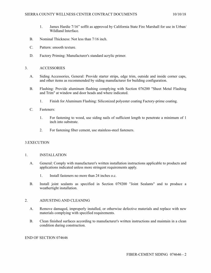
SIERRA COUNTY WELLNESS CENTER CONTRACT DOCUMENTS 10/10/18
1. James Hardie 7/16” soffit as approved by California State Fire Marshall for use in Urban/Wildland Interface.
B. Nominal Thickness: Not less than 7/16 inch.
C. Pattern: smooth texture.
D. Factory Priming: Manufacturer's standard acrylic primer.
3. ACCESSORIES
A. Siding Accessories, General: Provide starter strips, edge trim, outside and inside corner caps, and other items as recommended by siding manufacturer for building configuration.
B. Flashing: Provide aluminum flashing complying with Section 076200 "Sheet Metal Flashing and Trim" at window and door heads and where indicated.
1. Finish for Aluminum Flashing: Siliconized polyester coating Factory-prime coating.
C. Fasteners:
1. For fastening to wood, use siding nails of sufficient length to penetrate a minimum of 1 inch into substrate.
2. For fastening fiber cement, use stainless-steel fasteners.
3.EXECUTION
1. INSTALLATION
A. General: Comply with manufacturer's written installation instructions applicable to products and applications indicated unless more stringent requirements apply.
1. Install fasteners no more than 24 inches o.c.
B. Install joint sealants as specified in Section 079200 "Joint Sealants" and to produce a weathertight installation.
2. ADJUSTING AND CLEANING
A. Remove damaged, improperly installed, or otherwise defective materials and replace with new materials complying with specified requirements.
B. Clean finished surfaces according to manufacturer's written instructions and maintain in a clean condition during construction.
END OF SECTION 074646
FIBER-CEMENT SIDING 074646 - ! 2

SIERRA COUNTY WELLNESS CENTER CONTRACT DOCUMENTS 10/10/18
SECTION 081433 - STILE AND RAIL WOOD DOORS
1.GENERAL
1. SUMMARY
A. Section Includes:
1. Exterior stile and rail wood doors and sidelites. 2. Interior stile and rail wood doors. 3. Interior fire-rated, stile and rail wood doors. 4. Finishing stile and rail wood doors. 5. Fitting stile and rail wood doors to frames and machining for hardware. 6. Prehanging doors in frames.
2.PRODUCTS
1. MATERIALS
A. General: Use only materials that comply with referenced standards and other requirements specified. Assemble exterior doors and sidelites with wet-use adhesives.
B. Low-Emitting Materials: Fabricate doors with adhesives and composite wood products that do not contain urea formaldehyde.
2. EXTERIOR STILE AND RAIL WOOD DOORS
A. Thermal Transmittance: Maximum whole fenestration product U-factor of 0.35, according to AAMA 1503, ASTM E 1423, or NFRC 100.
B. Exterior Stile and Rail Wood Doors: Exterior doors complying with WDMA I.S.6, "Industry Standard for Wood Stile and Rail Doors," and with other requirements specified. 1. Finish and Grade: Opaque and Standard. 2. Wood Species: Manufacturer's standard softwood species and cut. 3. Glass: Uncoated, clear, fully tempered float glass, or laminated glass made from two lites
of 3.0-mm-thick annealed glass 4. Exterior Stile and Rail Wood Doors: Exterior stock doors complying with "Industry
Standard for Architectural Stile and Rail Doors," and with other requirements specified. 5. Finish: Opaque.
3. INTERIOR STILE AND RAIL WOOD DOORS
A. Interior Stile and Rail Wood Doors: Interior doors complying with WDMA I.S.6, "Industry Standard for Wood Stile and Rail Doors," and with other requirements specified. 1. Opaque and Standard. 2. Wood Species:Manufacturer's standard softwood species and cut Douglas fir 3. Glass: Uncoated, clear, fully tempered float glass, 5.0 mm thick
STILE AND RAIL WOOD DOORS 081433 - ! 1

SIERRA COUNTY WELLNESS CENTER CONTRACT DOCUMENTS 10/10/18
B. Interior Stile and Rail Wood Doors: Interior stock doors complying with "Industry Standard for Architectural Stile and Rail Doors," and with other requirements specified. 1. Grade: Custom. 2. Finish: Opaque. 3. Species indicated in schedule 4. Door Construction for Opaque Finish:
a. Stile and Rail Construction: Clear softwood; may be edge glued for width and finger jointed.
b. Stile and Rail Construction: Veneered, structural composite lumber or veneered edge- and end-glued lumber.
c. Raised-Panel Construction: Clear softwood lumber; edge glued for width.
5. Raised-Panel Thickness: As indicated. 6. Glass: Uncoated, clear, fully tempered float glass, 5.0 mm thick
4. INTERIOR FIRE-RATED, STILE AND RAIL WOOD DOORS
A. Fire-Rated Wood Doors: Doors complying with NFPA 80 that are listed and labeled by a qualified testing agency, for fire-protection ratings indicated, based on testing at positive pressure according to NFPA 252 or UL 10C.
1. Edge Construction: Provide edge construction with intumescent seals concealed by outer stile. Comply with specified requirements for exposed edges.
2. Pairs: Provide fire-retardant stiles that are listed and labeled for applications indicated without formed-steel edges and astragals. Provide stiles with concealed intumescent seals. Comply with specified requirements for exposed edges.
B. Prehung Doors: Provide stile and rail doors complete with frames, [weather stripping, ]and hardware.
1. Provide wood door frames that comply with Section 062023 "Interior Finish Carpentry." 2. Provide hardware, including weather stripping, that complies with Section 087100 "Door
Hardware."
5. SHOP PRIMING
A. Doors for Opaque Finish: Shop prime faces, all four edges, edges of cutouts, and mortises with one coat of wood primer.
6. FINISHING
A. Use only paints and coatings that comply with the testing and product requirements of the California Department of Health Services' "Standard Practice for the Testing of Volatile Organic Emissions from Various Sources Using Small-Scale Environmental Chambers."
STILE AND RAIL WOOD DOORS 081433 - ! 2

SIERRA COUNTY WELLNESS CENTER CONTRACT DOCUMENTS 10/10/18
3.EXECUTION
1. INSTALLATION
A. Hardware: For installation, see Section 087100 "Door Hardware."
B. Installation Instructions: Install doors to comply with manufacturer's written instructions and referenced quality standard, and as indicated.
1. Install fire-rated doors according to NFPA 80. 2. Install smoke- and draft-control doors according to NFPA 105.
C. Job-Fitted Doors: Align and fit doors in frames with uniform clearances and bevels as indicated below; do not trim stiles and rails in excess of limits set by manufacturer or permitted with fire-rated doors. Machine doors for hardware. Seal edges of doors, edges of cutouts, and mortises after fitting and machining.
1. Clearances: Provide 1/8 inch at heads, jambs, and between pairs of doors. Provide 1/4 inch from bottom of door to top of decorative floor finish or covering unless otherwise indicated. Where threshold is shown or scheduled, provide1/4 inch from bottom of door to top of threshold unless otherwise indicated.
a. Comply with NFPA 80 for fire-rated doors.
2. Bevel non-fire-rated doors 1/8 inch in 2 inches at lock and hinge edges. 3. Bevel fire-rated doors 1/8 inch in 2 inches on lock edge; trim stiles and rails only to
extent permitted by labeling agency.
D. Factory-Fitted Doors: Align in frames for uniform clearance at each edge.
END OF SECTION 081433
STILE AND RAIL WOOD DOORS 081433 - ! 3

SIERRA COUNTY WELLNESS CENTER CONTRACT DOCUMENTS 10/10/18
SECTION 085313 - VINYL WINDOWS
1.GENERAL
1. SUMMARY
A. Section includes vinyl-framed windows.
2. ACTION SUBMITTALS
A. Product Data: For each type of product.
B. Product Schedule: For vinyl windows. Use same designations indicated on Drawings.
3. WARRANTY
A. Manufacturer's Warranty: Manufacturer agrees to repair or replace vinyl windows that fail in materials or workmanship within specified warranty period.
1. Warranty Period:
a. Window: 10 years from date of Substantial Completion. b. Glazing Units: 10 years from date of Substantial Completion.
2.PRODUCTS
1. MANUFACTURERS
A. Sierra Pacific Windows and Doors, or approved equal
2. WINDOW PERFORMANCE REQUIREMENTS
A. Product Standard: AAMA/WDMA/CSA 101/I.S.2/A440.
1. Minimum Performance Class: As indicated on Drawings..
B. Thermal Transmittance: NFRC 100 maximum whole-window U-factor as indicated on drawings.
C. Solar Heat-Gain Coefficient (SHGC): NFRC 200 maximum whole-window SHGC as indicated on drawings.
3. VINYL WINDOWS
A. Operating Types: As indicated on Drawings.
VINYL WINDOWS 085313 - ! 1

SIERRA COUNTY WELLNESS CENTER CONTRACT DOCUMENTS 10/10/18
B. Frames and Sashes: Impact-resistant, UV-stabilized PVC complying with AAMA/WDMA/CSA 101/I.S.2/A440.
1. Finish: Integral color, as indicated on drawings.
C. Glass: Clear annealed glass, ASTM C 1036, Type 1, Class 1, q3.
1. Kind: Fully tempered.
D. Insulating-Glass Units: ASTM E 2190.
1. Glass: ASTM C 1036, Type 1, Class 1, q3.
a. Tint: Clear b. Kind: Fully tempered where indicated on Drawings.
2. Filling: Fill space between glass lites with air. 3. Low-E Coating: Pyrolytic on second surface. 4. Glazing System: Manufacturer's standard factory-glazing system that produces
weathertight seal.
E. Hardware, General: Manufacturer's standard corrosion-resistant material sized to accommodate sash weight and dimensions.
F. Projected Window Hardware:
1. Gear-Type Rotary Operators: Complying with AAMA 901 when tested according to ASTM E 405, Method A. Provide operators that function without requiring the removal of interior screens or using screen wickets.
a. Type and Style: As selected by Architect from manufacturer's full range of types and styles.
2. Hinges: Manufacturer's standard type for sash weight and size indicated. 3. Single-Handle Locking System: Operates positive-acting arms that pull sash into locked
position. Provide one arm on sashes up to 29 inches (735 mm) tall and two arms on taller sashes.
G. Weather Stripping: Provide full-perimeter weather stripping for each operable sash unless otherwise indicated.
H. Fasteners: Noncorrosive and compatible with window members, trim, hardware, anchors, and other components.
1. Exposed Fasteners: Do not use exposed fasteners to the greatest extent possible. For application of hardware, use fasteners that match finish hardware being fastened.
4. INSECT SCREENS
A. General: Fabricate insect screens to fully integrate with window frame. Provide screen for each operable exterior sash. Screen wickets are not permitted.
1. Mesh Color: Manufacturer's standard.
VINYL WINDOWS 085313 - ! 2

SIERRA COUNTY WELLNESS CENTER CONTRACT DOCUMENTS 10/10/18
3.EXECUTION
1. INSTALLATION
A. Comply with manufacturer's written instructions for installing windows, hardware, accessories, and other components. For installation procedures and requirements not addressed in manufacturer's written instructions, comply with installation requirements in ASTM E 2112.
B. Install windows level, plumb, square, true to line, without distortion, anchored securely in place to structural support, and in proper relation to wall flashing and other adjacent construction to produce weathertight construction.
C. Adjust operating sashes and hardware for a tight fit at contact points and weather stripping for smooth operation and weathertight closure.
D. Clean exposed surfaces immediately after installing windows. Remove excess sealants, glazing materials, dirt, and other substances.
E. Remove and replace sashes if glass has been broken, chipped, cracked, abraded, or damaged during construction period.
END OF SECTION 085313
VINYL WINDOWS 085313 - ! 3

SIERRA COUNTY WELLNESS CENTER CONTRACT DOCUMENTS 10/10/18
SECTION 087100 - DOOR HARDWARE
1.GENERAL
1. SUMMARY
A. Section includes:
1. Mechanical door hardware for the following:
a. Swinging doors. b. Sliding doors.
2. ACTION SUBMITTALS
A. Product Data: For each type of product indicated.
B. Other Action Submittals:
1. Door Hardware Schedule: Prepared by or under the supervision of Installer, detailing fabrication and assembly of door hardware, as well as installation procedures and diagrams. Coordinate final door hardware schedule with doors, frames, and related work to ensure proper size, thickness, hand, function, and finish of door hardware.
2. Keying Schedule: Prepared by or under the supervision of Installer, detailing Owner's final keying instructions for locks.
3. WARRANTY
A. Special Warranty: Manufacturer's standard form in which manufacturer agrees to repair or replace components of door hardware that fail in materials or workmanship within specified warranty period.
1. Warranty Period: Three years from date of Substantial Completion, unless otherwise indicated.
2.PRODUCTS
1. SCHEDULED DOOR HARDWARE
A. Provide door hardware for each door as scheduled on Drawings to comply with requirements in this Section.
1. Door Hardware Sets: Provide quantity, item, size, finish or color indicated, and named manufacturers' products.
2. Sequence of Operation: Provide electrified door hardware function, sequence of operation, and interface with other building control systems indicated.
DOOR HARDWARE 087100 - ! 1

SIERRA COUNTY WELLNESS CENTER CONTRACT DOCUMENTS 10/10/18
B. Designations: Requirements for design, grade, function, finish, size, and other distinctive qualities of each type of door hardware are indicated in Part 3 "Door Hardware Schedule" Article. Products are identified by using door hardware designations, as follows:
1. Named Manufacturers' Products: Manufacturer and product designation are listed for each door hardware type required for the purpose of establishing minimum requirements. Manufacturers' names are abbreviated in Part 3 "Door Hardware Schedule" Article.
2. References to BHMA Designations: Provide products complying with these designations and requirements for description, quality, and function.
2. HINGES
A. Hinges: BHMA A156.1.
3. MECHANICAL LOCKS AND LATCHES
A. Strikes: Provide manufacturer's standard strike for each lock bolt or latchbolt complying with requirements indicated for applicable lock or latch and with strike box and curved lip extended to protect frame; finished to match lock or latch. 1. Extra-Long-Lip Strikes: For locks used on frames with applied wood casing trim.
B. Bored Locks: BHMA A156.2.
4. AUXILIARY LOCKS
A. Bored Auxiliary Locks: BHMA A156.5 with strike that suits frame.
5. LOCK CYLINDERS
A. Lock Cylinders: Tumbler type, constructed from brass or bronze, stainless steel, or nickel silver.
1. Manufacturer: Same manufacturer as for locking devices.
6. KEYING
A. Keying System: Factory registered, complying with guidelines in BHMA A156.28, Appendix A. Incorporate decisions made in keying conference. 1. Master Key System: Change keys and a master key operate cylinders.
2. Quantity: In addition to one extra key blank for each lock, provide the following:
a. Cylinder Change Keys: Three. b. Master Keys: Five. c. Grand Master Keys: Five. d. Great-Grand Master Keys: Five.
DOOR HARDWARE 087100 - ! 2

SIERRA COUNTY WELLNESS CENTER CONTRACT DOCUMENTS 10/10/18
7. SURFACE CLOSERS
A. Surface Closers: BHMA A156.4; rack-and-pinion hydraulic type with adjustable sweep and latch speeds controlled by key-operated valves and forged-steel main arm. Comply with manufacturer's written recommendations for size of door closers depending on size of door, exposure to weather, and anticipated frequency of use. Provide factory-sized closers, adjustable to meet field conditions and requirements for opening force
8. MECHANICAL STOPS AND HOLDERS
A. Wall- and Floor-Mounted Stops: BHMA A156.16; polished cast brass, bronze, or aluminum base metal.
9. DOOR GASKETING
A. Door Gasketing: BHMA A156.22; air leakage not to exceed 0.50 cfm per foot of crack length for gasketing other than for smoke control, as tested according to ASTM E 283; with resilient or flexible seal strips that are easily replaceable and readily available from stocks maintained by manufacturer.
10. THRESHOLDS
A. Thresholds: BHMA A156.21; fabricated to full width of opening indicated.
11. POCKET DOOR HARDWARE
A. Pocket Door Hardware: BHMA A156.14; consisting of complete sets including rails, hangers, supports, bumpers, latches, floor guides, and accessories indicated.
12. FINISHES
A. Provide finishes complying with BHMA A156.18 as indicated in door hardware schedule.
B. Protect mechanical finishes on exposed surfaces from damage by applying a strippable, temporary protective covering before shipping.
3.EXECUTION
1. INSTALLATION
A. Steel Doors and Frames: For surface applied door hardware, drill and tap doors and frames according to ANSI/SDI A250.6.
B. Wood Doors: Comply with DHI WDHS.5 "Recommended Hardware Reinforcement Locations for Mineral Core Wood Flush Doors."
DOOR HARDWARE 087100 - ! 3

SIERRA COUNTY WELLNESS CENTER CONTRACT DOCUMENTS 10/10/18
C. Mounting Heights: Mount door hardware units at heights to comply with the following unless otherwise indicated or required to comply with governing regulations.. 1. Wood Doors: DHI WDHS.3, "Recommended Locations for Architectural Hardware for
Wood Flush Doors."
D. Install each door hardware item to comply with manufacturer's written instructions. Where cutting and fitting are required to install door hardware onto or into surfaces that are later to be painted or finished in another way, coordinate removal, storage, and reinstallation of surface protective trim units with finishing work. Do not install surface-mounted items until finishes have been completed on substrates involved.
1. Set units level, plumb, and true to line and location. Adjust and reinforce attachment substrates as necessary for proper installation and operation.
2. Drill and countersink units that are not factory prepared for anchorage fasteners. Space fasteners and anchors according to industry standards.
E. Hinges: Install types and in quantities indicated in door hardware schedule but not fewer than the number recommended by manufacturer for application indicated or one hinge for every 30 inches of door height, whichever is more stringent, unless other equivalent means of support for door, such as spring hinges or pivots, are provided.
F. Lock Cylinders: Install construction cores to secure building and areas during construction period.
G. Thresholds: Set thresholds for exterior doors and other doors indicated in full bed of sealant complying with requirements specified in Section 079200 "Joint Sealants."
H. Stops: Provide floor stops for doors unless wall or other type stops are indicated in door hardware schedule. Do not mount floor stops where they will impede traffic.
I. Perimeter Gasketing: Apply to head and jamb, forming seal between door and frame.
J. Meeting Stile Gasketing: Fasten to meeting stiles, forming seal when doors are closed.
K. Door Bottoms: Apply to bottom of door, forming seal with threshold when door is closed.
L. Adjustment: Adjust and check each operating item of door hardware and each door to ensure proper operation or function of every unit. Replace units that cannot be adjusted to operate as intended. Adjust door control devices to compensate for final operation of heating and ventilating equipment and to comply with referenced accessibility requirements.
END OF SECTION 087100
DOOR HARDWARE 087100 - ! 4

SIERRA COUNTY WELLNESS CENTER CONTRACT DOCUMENTS 10/10/18
SECTION 092900 - GYPSUM BOARD
1.GENERAL
1. SUMMARY
A. Section Includes:
1. Interior gypsum board. 2. Texture finishes.
2. ACTION SUBMITTALS
A. Product Data: For each type of product.
B. Samples:
1. Textured Finishes: for each textured finish indicated and on same backing indicated for Work.
2.PRODUCTS
1. PERFORMANCE REQUIREMENTS
A. Fire-Resistance-Rated Assemblies: For fire-resistance-rated assemblies, provide materials and construction identical to those tested in assembly indicated according to ASTM E 119 by an independent testing agency.
B. Low Emitting Materials: For ceiling and wall assemblies, provide materials and construction identical to those tested in assembly and complying with the testing and product requirements of the California Department of Health Services' "Standard Practice for the Testing of Volatile Organic Emissions from Various Sources Using Small-Scale Environmental Chambers."
2. INTERIOR GYPSUM BOARD
A. Manufacturers: Subject to compliance with requirements, provide products by the following:
1. American Gypsum. 2. CertainTeed Corp. 3. Georgia-Pacific Gypsum LLC. 4. Lafarge North America Inc. 5. National Gypsum Company. 6. PABCO Gypsum. 7. Temple-Inland. 8. USG Corporation.
B. Gypsum Board, Type X: ASTM C 1396/C 1396M.
GYPSUM BOARD 092900 - ! 1

SIERRA COUNTY WELLNESS CENTER CONTRACT DOCUMENTS 10/10/18
1. Thickness: 5/8 inch 2. Long Edges: Tapered
C. Moisture- and Mold-Resistant Gypsum Board: ASTM C 1396/C 1396M. With moisture- and mold-resistant core and paper surfaces.
1. Core: 5/8 inch, Type X. 2. Long Edges: Tapered. 3. Mold Resistance: ASTM D 3273, score of 10.
D. Cementitious Backer Units: ANSI A118.9 and ASTM C 1288 or 1325, with manufacturer's standard edges.
1. Products: Subject to compliance with requirements, provide one of the following available products that may be incorporated into the Work include, but are not limited to, the following: a. CertainTeed Corp.; FiberCement BackerBoard. b. Custom Building Products; Wonderboard c. James Hardie Building Products, Inc.; Hardiebacker, Hardiebacker 500. d. National Gypsum Company, Permabase Cement Board. e. USG Corporation; DUROCK Cement Board.
2. Mold Resistance: ASTM D 3273, score of 10.
3. TRIM ACCESSORIES
A. Interior Trim: ASTM C 1047.
1. Material: Galvanized or aluminum-coated steel sheet, rolled zinc, plastic, or paper-faced galvanized steel sheet
4. JOINT TREATMENT MATERIALS
A. General: Comply with ASTM C 475/C 475M.
B. Joint Tape:
1. Interior Gypsum Board: Paper. 2. Glass-Mat Gypsum Sheathing Board: 10-by-10 glass mesh. 3. Tile Backing Panels: As recommended by panel manufacturer.
C. Joint Compound for Interior Gypsum Board: For each coat use formulation that is compatible with other compounds applied on previous or for successive coats.
5. TEXTURE FINISHES
A. Primer: As recommended by textured finish manufacturer.
B. Non-Aggregate Finish: Pre-mixed, vinyl texture finish for spray application.
1. Products: Subject to compliance with requirements,
GYPSUM BOARD 092900 - ! 2

SIERRA COUNTY WELLNESS CENTER CONTRACT DOCUMENTS 10/10/18
2. Texture: Orange Peel.
3.EXECUTION
1. APPLYING AND FINISHING PANELS
A. Comply with ASTM C 840.
B. Examine panels before installation. Reject panels that are wet, moisture damaged, and mold damaged.
C. Isolate perimeter of gypsum board applied to non-load-bearing partitions at structural abutments, except floors. Provide 1/4- to 1/2-inch- wide spaces at these locations and trim edges with edge trim where edges of panels are exposed. Seal joints between edges and abutting structural surfaces with acoustical sealant.
D. Install trim with back flanges intended for fasteners, attach to framing with same fasteners used for panels. Otherwise, attach trim according to manufacturer's written instructions.
E. Apply joint tape over gypsum board joints, except for trim products specifically indicated as not intended to receive tape.
F. Texture Finish Application: Prepare and apply primer to gypsum panels and other surfaces receiving texture finishes. Mix and apply finish using powered spray equipment, to produce a uniform texture matching approved mockup and free of starved spots or other evidence of thin application or of application patterns.
G. Protect adjacent surfaces from drywall compound and texture finishes and promptly remove from floors and other non-drywall surfaces. Repair surfaces stained, marred, or otherwise damaged during drywall application.
H. Remove and replace panels that are wet, moisture damaged, and mold damaged.
END OF SECTION 092900
GYPSUM BOARD 092900 - ! 3

SIERRA COUNTY WELLNESS CENTER CONTRACT DOCUMENTS 10/10/18
SECTION 096513 - RESILIENT BASE AND ACCESSORIES
1.GENERAL
1. SUMMARY
A. Section Includes:
1. Resilient base. 2. Resilient molding accessories.
2. ACTION SUBMITTALS
A. Product Data: For each type of product.
2.PRODUCTS
1. THERMOSET-RUBBER BASE
2. Product Standard: ASTM F 1861, Type TS (rubber, vulcanized thermoset), Group I (solid, homogeneous).
1. Style and Location:
a. Style A, Straight: Provide in areas with carpeting and resilient flooring unless otherwise indicated on drawings.
b. Thickness: 0.125 inch.
B. Height: 4 inches.
C. Lengths: Coils in manufacturer's standard length or Cut lengths 48 inches long or coils in manufacturer's standard length.
D. Outside Corners: Job formed or preformed.
E. Inside Corners: Job formed or preformed.
F. Colors: As selected by Architect from full range of industry colors..
3. INSTALLATION MATERIALS
A. Trowelable Leveling and Patching Compounds: Latex-modified, portland cement based or blended hydraulic-cement-based formulation provided or approved by resilient-product manufacturer for applications indicated.
RESILIENT BASE AND ACCESSORIES 096513 - ! 1

SIERRA COUNTY WELLNESS CENTER CONTRACT DOCUMENTS 10/10/18
B. Adhesives: Water-resistant type recommended by resilient-product manufacturer for resilient products and substrate conditions indicated.
1. Adhesives shall have a VOC content of 50 g/L or less
2. Adhesives shall comply with the testing and product requirements of the California Department of Public Health's "Standard Method for the Testing and Evaluation of Volatile Organic Chemical Emissions from Indoor Sources Using Environmental Chambers."
3.EXECUTION
1. PREPARATION
A. Prepare substrates according to manufacturer's written instructions to ensure adhesion of resilient products.
B. Do not install resilient products until they are the same temperature as the space where they are to be installed.
C. Immediately before installation, sweep and vacuum clean substrates to be covered by resilient products.
2. RESILIENT BASE INSTALLATION
A. Comply with manufacturer's written instructions for installing resilient base.
B. Apply resilient base to walls, columns, pilasters, casework and cabinets in toe spaces, and other permanent fixtures in rooms and areas where base is required.
C. Install resilient base in lengths as long as practical without gaps at seams and with tops of adjacent pieces aligned.
D. Tightly adhere resilient base to substrate throughout length of each piece, with base in continuous contact with horizontal and vertical substrates.
E. Do not stretch resilient base during installation.
F. Preformed Corners: Install preformed corners before installing straight pieces.
3. CLEANING AND PROTECTION
A. Comply with manufacturer's written instructions for cleaning and protecting resilient products.
END OF SECTION 096513
RESILIENT BASE AND ACCESSORIES 096513 - ! 2

SIERRA COUNTY WELLNESS CENTER CONTRACT DOCUMENTS 10/10/18
SECTION 096516 - RESILIENT SHEET FLOORING
1.GENERAL
1. SUMMARY
A. Section includes vinyl sheet flooring.
2. ACTION SUBMITTALS
A. Product Data: For each type of product.
B. Samples: For each exposed product and for each color and texture specified in manufacturer's standard size, but not less than 6-by-9-inch sections.
1. For heat-welding bead, manufacturer's standard-size Samples, but not less than 9 inches long, of each color required.
3. CLOSEOUT SUBMITTALS
A. Maintenance data.
2.PRODUCTS
1. VINYL SHEET FLOORING
A. Tarkett Lifetime Quartzite Tile, White, #38913 seamless sheet, or approved equal..
B. Product Standard: ASTM F 1913.
C. Thickness: 0.080 inch.
D. Wearing Surface: Embossed.
E. Sheet Width: As standard with manufacturer.
F. Seamless-Installation Method: Heat welded.
G. Colors and Patterns: As selected by Architect from full range of industry colors.
2. INSTALLATION MATERIALS
A. Trowelable Leveling and Patching Compounds: Latex-modified, portland cement based or blended hydraulic-cement-based formulation provided or approved by resilient sheet flooring manufacturer for applications indicated.
RESILIENT SHEET FLOORING 096516 - ! 1

SIERRA COUNTY WELLNESS CENTER CONTRACT DOCUMENTS 10/10/18
B. Adhesives: Water-resistant type recommended by flooring and adhesive manufacturers to suit resilient sheet flooring and substrate conditions indicated.
1. Adhesives shall have a VOC content of [50] [60] <Insert value> g/L or less. 2. Adhesives shall comply with the testing and product requirements of the California
Department of Public Health's "Standard Method for the Testing and Evaluation of Volatile Organic Chemical Emissions from Indoor Sources Using Environmental Chambers."
C. Seamless-Installation Accessories:
1. Heat-Welding Bead: Manufacturer's solid-strand product for heat welding seams.
a. Color: As selected by Architect from manufacturer's full range to Match flooring.
D. Integral-Flash-Cove-Base Accessories:
1. Cove Strip: 1-inch radius provided or approved by resilient sheet flooring manufacturer. 2. Cap Strip: Square metal, vinyl, or rubber cap provided or approved by resilient sheet
flooring manufacturer. 3. Corners: Metal inside and outside corners and end stops provided or approved by resilient
sheet flooring manufacturer.
E. Floor Polish: Provide protective, liquid floor-polish products recommended by resilient sheet flooring manufacturer.
3.EXECUTION
1. PREPARATION
A. Prepare substrates according to resilient sheet flooring manufacturer's written instructions to ensure adhesion of resilient sheet flooring.
1. Verify that substrates are dry and free of curing compounds, sealers, and hardeners. 2. Remove substrate coatings and other substances that are incompatible with adhesives and
that contain soap, wax, oil, or silicone, using mechanical methods recommended by resilient sheet flooring manufacturer. Do not use solvents.
B. Fill cracks, holes, and depressions in substrates with trowelable leveling and patching compound; remove bumps and ridges to produce a uniform and smooth substrate.
C. Do not install resilient sheet flooring until it is the same temperature as the space where it is to be installed.
D. Immediately before installation, sweep and vacuum clean substrates to be covered by resilient sheet flooring.
2. RESILIENT SHEET FLOORING INSTALLATION
A. Comply with manufacturer's written instructions for installing resilient sheet flooring.
RESILIENT SHEET FLOORING 096516 - ! 2

SIERRA COUNTY WELLNESS CENTER CONTRACT DOCUMENTS 10/10/18
B. Unroll resilient sheet flooring and allow it to stabilize before cutting and fitting.
C. Lay out resilient sheet flooring as follows:
1. Maintain uniformity of flooring direction. 2. Minimize number of seams; place seams in inconspicuous and low-traffic areas, at least
12 inches away from parallel joints in flooring substrates. 3. Match edges of flooring for color shading at seams. 4. Avoid cross seams.
D. Scribe and cut resilient sheet flooring to butt neatly and tightly to vertical surfaces, permanent fixtures, and built-in furniture including cabinets, pipes, outlets, and door frames.
E. Extend resilient sheet flooring into toe spaces, door reveals, closets, and similar openings.
F. Maintain reference markers, holes, and openings that are in place or marked for future cutting by repeating on resilient sheet flooring as marked on substrates. Use chalk or other nonpermanent marking device.
G. Adhere resilient sheet flooring to substrates using a full spread of adhesive applied to substrate to produce a completed installation without open cracks, voids, raising and puckering at joints, telegraphing of adhesive spreader marks, and other surface imperfections.
H. Seamless Installation:
1. Heat-Welded Seams: Comply with ASTM F 1516. Rout joints and heat weld with welding bead to permanently fuse sections into a seamless flooring. Prepare, weld, and finish seams to produce surfaces flush with adjoining flooring surfaces.
I. Integral-Flash-Cove Base: Cove resilient sheet flooring [6 inches up vertical surfaces. Support flooring at horizontal and vertical junction with cove strip. Butt at top against cap strip.
1. Install metal corners at inside and outside corners.
3. CLEANING AND PROTECTION
A. Comply with manufacturer's written instructions for cleaning and protecting resilient sheet flooring.
B. Floor Polish: Remove soil, adhesive, and blemishes from flooring surfaces before applying liquid floor polish.
1. Apply two] coat(s).
C. Cover resilient sheet flooring until Substantial Completion.
END OF SECTION 096516
RESILIENT SHEET FLOORING 096516 - ! 3

SIERRA COUNTY WELLNESS CENTER CONTRACT DOCUMENTS 10/10/18
SECTION 096816 - SHEET CARPETING
1.GENERAL
1. SUMMARY
A. Section includes woven monolithic carpet.
2. PREINSTALLATION MEETINGS
A. Preinstallation Conference: Conduct conference at Project site.
3. ACTION SUBMITTALS
A. Product Data: For each type of product.
B. Samples: For each exposed product and for each color and texture specified.
4. CLOSEOUT SUBMITTALS
A. Maintenance data.
5. QUALITY ASSURANCE
A. Installer Qualifications: An experienced Installer who is certified by the International Certified Floor covering Installers Association at the Commercial II certification level.
B. Fire-Test-Response Ratings: Where indicated, provide carpet identical to those of assemblies tested for fire response per NFPA 253 by a qualified testing agency.
6. DELIVERY, STORAGE, AND HANDLING
A. Comply with CRI 104.
7. FIELD CONDITIONS
A. Comply with CRI 104 for temperature, humidity, and ventilation limitations.
8. WARRANTY
A. Special Warranty for Carpet: Manufacturer agrees to repair or replace components of carpet installation that fail in materials or workmanship within specified warranty period.
1. Warranty does not include deterioration or failure of carpet due to unusual traffic, failure of substrate, vandalism, or abuse.
SHEET CARPETING 096816 - ! 1

SIERRA COUNTY WELLNESS CENTER CONTRACT DOCUMENTS 10/10/18
2. Failures include, but are not limited to, more than 10 percent loss of face fiber, edge raveling, snags, runs, loss of tuft bind strength, excess static discharge, and delamination.
3. Warranty Period: 10 years from date of Substantial Completion.
2.PRODUCTS
1. WOVEN CARPET
A. Products: Subject to compliance with requirements, provide the following:
1. Shaw Contract Carpet: Noble materials, style 5A219 woven pattern loop, or approved equal..
B. Color: As selected by Architect from manufacturer's full range..
C. Fiber Content: 100 percent Nylon..
D. Pile Characteristic: Cut-and-loop pile.
E. Density: 7558/CY.
F. Pile Thickness: 0.181 for finished carpet.
G. Rows: 216 lengthwise tufts per inch.
H. Pitch: 7.0 rows in 27 inches.
I. Face Weight: 38.0 oz./sq. yd...
J. Backing: Manufacturer's standard.
K. Applied Soil-Resistance Treatment: Manufacturer's standard material.
L. Antimicrobial Treatment: Manufacturer's standard material.
M. Performance Characteristics: As follows:
1. Appearance Retention Rating: Moderate traffic, 2.5. 2. Critical Radiant Flux Classification: Not less than 0.45 W/sq. cm. 3. Electrostatic Propensity: Less than 3.5 kV per AATCC 134. 4. Emissions: Provide carpet that complies with testing and product requirements of CRI's
"Green Label Plus" program. 5. Emissions: Provide carpet that complies with the product requirements of the California
Department of Health Services' "Standard Practice for the Testing of Volatile Organic Emissions from Various Sources Using Small-Scale Environmental Chambers."
2. INSTALLATION ACCESSORIES
A. Trowelable Leveling and Patching Compounds: Latex-modified, hydraulic-cement-based formulation provided or recommended by carpet[ cushion] manufacturer.
SHEET CARPETING 096816 - ! 2

SIERRA COUNTY WELLNESS CENTER CONTRACT DOCUMENTS 10/10/18
B. Adhesives: Water-resistant, mildew-resistant, nonstaining type to suit products and subfloor conditions indicated, that complies with flammability requirements for installed carpet and is recommended or provided by carpet manufacturer
C. Use adhesives with VOC content not more than 50 g/L when calculated according to 40 CFR 59, Subpart D (EPA Method 24). 1. Use adhesives that comply with the product requirements of the California Department of
Health Services' "Standard Practice for the Testing of Volatile Organic Emissions from Various Sources Using Small-Scale Environmental Chambers."
D. Tackless Carpet Stripping: Water-resistant plywood, in strips as required to match cushion thickness and that comply with CRI 104, Section 12.2.
E. Seam Adhesive: Hot-melt adhesive tape or similar product recommended by carpet manufacturer for sealing and taping seams and butting cut edges at backing to form secure seams and to prevent pile loss at seams.
3.EXECUTION
1. INSTALLATION
A. Examine substrates, areas, and conditions, with Installer present, for compliance with requirements for maximum moisture content, alkalinity range, installation tolerances, and other conditions affecting carpet performance. Examine carpet for type, color, pattern, and potential defects.
B. Proceed with installation only after unsatisfactory conditions have been corrected.
C. Preparation: Comply with CRI 104, Section 7.3, "Site Conditions; Floor Preparation," and with carpet manufacturer's written installation instructions for preparing substrates.
D. Installation: Comply with CRI 104 and carpet manufacturer's written installation instructions for the following:
1. Direct-Glue-Down Installation: Comply with CRI 104, Section 9, "Direct Glue-Down Installation."
E. Comply with carpet manufacturer's written recommendations and Shop Drawings for seam locations and direction of carpet; maintain uniformity of carpet direction and lay of pile. At doorways, center seams under the door in closed position.
F. Cut and fit carpet to butt tightly to vertical surfaces, permanent fixtures, and built-in furniture including cabinets, pipes, outlets, edgings, thresholds, and nosings. Bind or seal cut edges as recommended by carpet manufacturer.
G. Extend carpet into toe spaces, door reveals, closets, open-bottomed obstructions, removable flanges, alcoves, and similar openings.
H. Maintain reference markers, holes, and openings that are in place or marked for future cutting by repeating on finish flooring as marked on subfloor. Use nonpermanent, nonstaining marking device.
SHEET CARPETING 096816 - ! 3

SIERRA COUNTY WELLNESS CENTER CONTRACT DOCUMENTS 10/10/18
I. Install pattern parallel to walls and borders to comply with CRI 104, Section 15, "Patterned Carpet Installations" and with carpet manufacturer's written recommendations.
J. Perform the following operations immediately after installing carpet:
1. Remove excess adhesive, seam sealer, and other surface blemishes using cleaner recommended by carpet manufacturer.
2. Remove yarns that protrude from carpet surface. 3. Vacuum carpet using commercial machine with face-beater element.
K. Protect installed carpet to comply with CRI 104, Section 16, "Protecting Indoor Installations."
END OF SECTION 096816
SHEET CARPETING 096816 - ! 4

SIERRA COUNTY WELLNESS CENTER CONTRACT DOCUMENTS 10/10/18
SECTION 099113 - EXTERIOR PAINTING
1.GENERAL
1. SUMMARY
A. Section includes surface preparation and the application of paint systems on the following exterior substrates:
1. Fiber-cement board. 2. Steel and iron. 3. Galvanized metal. 4. Wood.
2. ACTION SUBMITTALS
A. Product Data: For each type of product. Include preparation requirements and application instructions.
3. QUALITY ASSURANCE
A. Mockups: Apply mockups of each paint system indicated and each color and finish selected to verify preliminary selections made under Sample submittals and to demonstrate aesthetic effects and set quality standards for materials and execution.
1. Architect will select one surface to represent surfaces and conditions for application of each paint system.
a. Vertical and Horizontal Surfaces: Provide samples of at least 10 sq. ft. (9 sq. m). b. Other Items: Architect will designate items or areas required.
2. Final approval of color selections will be based on mockups.
a. If preliminary color selections are not approved, apply additional mockups of additional colors selected by Architect at no added cost to Owner.
2.PRODUCTS
1. MANUFACTURERS
A. Benjamin Moore, Kelly Moore, or equal. Benjamin Moore paints listed as indication of quality.
B. Products: Subject to compliance with requirements, provide product listed in the Exterior Painting Schedule for the paint category indicated.
EXTERIOR PAINTING 099113 - ! 1

SIERRA COUNTY WELLNESS CENTER CONTRACT DOCUMENTS 10/10/18
2. PAINT, GENERAL
A. MPI Standards: Products shall comply with MPI standards indicated and shall be listed in its "MPI Approved Products Lists."
B. Material Compatibility:
1. Materials for use within each paint system shall be compatible with one another and substrates indicated, under conditions of service and application as demonstrated by manufacturer, based on testing and field experience.
2. For each coat in a paint system, products shall be recommended in writing by topcoat manufacturers for use in paint system and on substrate indicated.
C. VOC Content: Products shall comply with VOC limits of authorities having jurisdiction.
D. Colors: As selected by Architect from manufacturer's full range
E. Ten percent of surface area will be painted with deep tones.
3.EXECUTION
1. EXAMINATION
A. Examine substrates and conditions, with Applicator present, for compliance with requirements for maximum moisture content and other conditions affecting performance of the Work.
B. Maximum Moisture Content of Substrates: When measured with an electronic moisture meter as follows:
1. Concrete: 12 percent. 2. Fiber-Cement Board: 12 percent. 3. Wood: 15 percent.
C. Verify suitability of substrates, including surface conditions and compatibility with existing finishes and primers.
D. Proceed with coating application only after unsatisfactory conditions have been corrected.
1. Application of coating indicates acceptance of surfaces and conditions.
2. PREPARATION
A. Comply with manufacturer's written instructions and recommendations in "MPI Architectural Painting Specification Manual" applicable to substrates and paint systems indicated.
B. Remove hardware, covers, plates, and similar items already in place that are removable and are not to be painted. If removal is impractical or impossible because of size or weight of item, provide surface-applied protection before surface preparation and painting.
1. After completing painting operations, use workers skilled in the trades involved to reinstall items that were removed. Remove surface-applied protection.
EXTERIOR PAINTING 099113 - ! 2
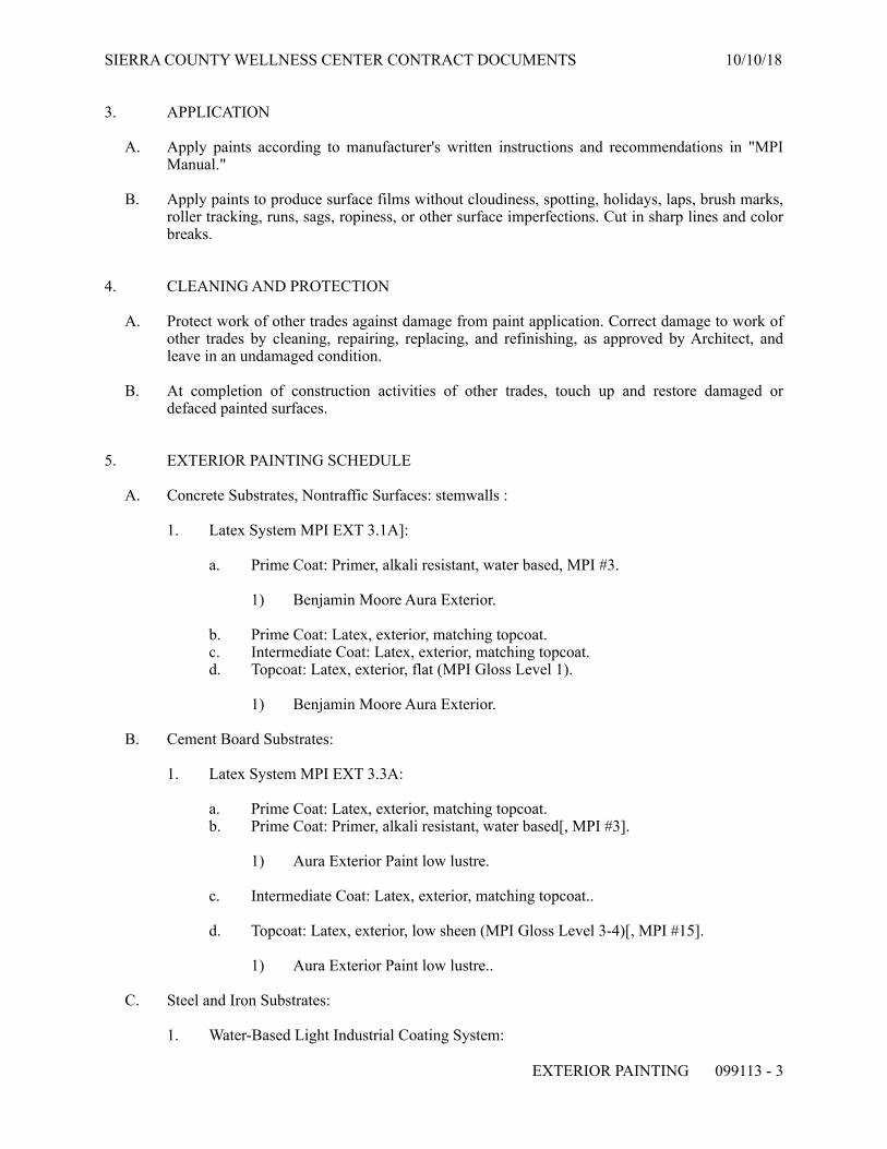
SIERRA COUNTY WELLNESS CENTER CONTRACT DOCUMENTS 10/10/18
3. APPLICATION
A. Apply paints according to manufacturer's written instructions and recommendations in "MPI Manual."
B. Apply paints to produce surface films without cloudiness, spotting, holidays, laps, brush marks, roller tracking, runs, sags, ropiness, or other surface imperfections. Cut in sharp lines and color breaks.
4. CLEANING AND PROTECTION
A. Protect work of other trades against damage from paint application. Correct damage to work of other trades by cleaning, repairing, replacing, and refinishing, as approved by Architect, and leave in an undamaged condition.
B. At completion of construction activities of other trades, touch up and restore damaged or defaced painted surfaces.
5. EXTERIOR PAINTING SCHEDULE
A. Concrete Substrates, Nontraffic Surfaces: stemwalls :
1. Latex System MPI EXT 3.1A]:
a. Prime Coat: Primer, alkali resistant, water based, MPI #3.
1) Benjamin Moore Aura Exterior.
b. Prime Coat: Latex, exterior, matching topcoat. c. Intermediate Coat: Latex, exterior, matching topcoat. d. Topcoat: Latex, exterior, flat (MPI Gloss Level 1).
1) Benjamin Moore Aura Exterior.
B. Cement Board Substrates:
1. Latex System MPI EXT 3.3A:
a. Prime Coat: Latex, exterior, matching topcoat. b. Prime Coat: Primer, alkali resistant, water based[, MPI #3].
1) Aura Exterior Paint low lustre.
c. Intermediate Coat: Latex, exterior, matching topcoat..
d. Topcoat: Latex, exterior, low sheen (MPI Gloss Level 3-4)[, MPI #15].
1) Aura Exterior Paint low lustre..
C. Steel and Iron Substrates:
1. Water-Based Light Industrial Coating System:
EXTERIOR PAINTING 099113 - ! 3

SIERRA COUNTY WELLNESS CENTER CONTRACT DOCUMENTS 10/10/18
a. Prime Coat: Shop primer specified in Section where substrate is specified. b. Intermediate Coat: Light industrial coating, exterior, water based, matching
topcoat..
c. Topcoat: Light industrial coating, exterior, water based, semi-gloss (MPI Gloss Level 5), .
1) Aura Exterior Paint semi gloss.
2) .
D. Galvanized-Metal Substrates:
1. Latex System:
a. Prime Coat: Primer, galvanized, water based[, MPI #134].
1) Aura Exterior Paint semi gloss.
b. Intermediate Coat: Latex, exterior, matching topcoat. c. Topcoat: Latex, exterior, semi gloss.
1) Aura Exterior Paint semi gloss.
E. Wood Substrates: Exposed framing.
1. Latex over Latex Primer System:
a. Prime Coat: Primer, latex for exterior wood, .
1) Benjamin Moore Aura Exterior Paint semi gloss..
b. Intermediate Coat: Latex, exterior, matching topcoat.
c. Topcoat: Latex, exterior, semi-gloss.
1) Benjamin Moore Aura Exterior Paint semi gloss.
F. Wood Substrates: Wood trim, Architectural woodwork.
1. Latex over Latex Primer System:
a. Prime Coat: Primer, latex for exterior wood.
1) Benjamin Moore Aura Exterior Paint semi gloss.
b. Intermediate Coat: Latex, exterior, matching topcoat..
c. Topcoat: Latex, exterior, semi-gloss (MPI Gloss Level 5).
1) Benjamin Moore Aura Exterior Paint semi gloss.
END OF SECTION 099113
EXTERIOR PAINTING 099113 - ! 4
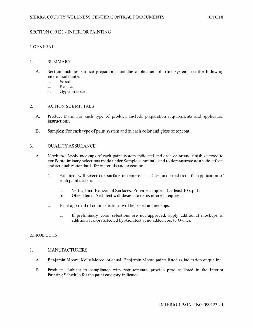
SIERRA COUNTY WELLNESS CENTER CONTRACT DOCUMENTS 10/10/18
SECTION 099123 - INTERIOR PAINTING
1.GENERAL
1. SUMMARY
A. Section includes surface preparation and the application of paint systems on the following interior substrates: 1. Wood. 2. Plastic. 3. Gypsum board.
2. ACTION SUBMITTALS
A. Product Data: For each type of product. Include preparation requirements and application instructions.
B. Samples: For each type of paint system and in each color and gloss of topcoat.
3. QUALITY ASSURANCE
A. Mockups: Apply mockups of each paint system indicated and each color and finish selected to verify preliminary selections made under Sample submittals and to demonstrate aesthetic effects and set quality standards for materials and execution.
1. Architect will select one surface to represent surfaces and conditions for application of each paint system.
a. Vertical and Horizontal Surfaces: Provide samples of at least 10 sq. ft.. b. Other Items: Architect will designate items or areas required.
2. Final approval of color selections will be based on mockups.
a. If preliminary color selections are not approved, apply additional mockups of additional colors selected by Architect at no added cost to Owner.
2.PRODUCTS
1. MANUFACTURERS
A. Benjamin Moore, Kelly Moore, or equal. Benjamin Moore paints listed as indication of quality.
B. Products: Subject to compliance with requirements, provide product listed in the Interior Painting Schedule for the paint category indicated.
INTERIOR PAINTING 099123 - ! 1

SIERRA COUNTY WELLNESS CENTER CONTRACT DOCUMENTS 10/10/18
2. PAINT, GENERAL
A. MPI Standards: Products shall comply with MPI standards indicated and shall be listed in its "MPI Approved Products Lists."
B. Material Compatibility:
1. Materials for use within each paint system shall be compatible with one another and substrates indicated, under conditions of service and application as demonstrated by manufacturer, based on testing and field experience.
2. For each coat in a paint system, products shall be recommended in writing by topcoat manufacturers for use in paint system and on substrate indicated.
C. VOC Content: Products shall comply with VOC limits of authorities having jurisdiction and, for interior paints and coatings applied at Project site, the following VOC limits, exclusive of colorants added to a tint base:
1. Flat Paints and Coatings: 50 g/L. 2. Nonflat Paints and Coatings: 150 g/L. 3. Primers, Sealers, and Undercoaters: 200 g/L. 4. Pretreatment Wash Primers: 420 g/L.
D. Low-Emitting Materials: Interior paints and coatings shall comply with the testing and product requirements of the California Department of Public Health's "Standard Method for the Testing and Evaluation of Volatile Organic Chemical Emissions from Indoor Sources Using Environmental Chambers."
E. Colors: As selected by Architect from manufacturer's full range.
1. Ten percent of surface area will be painted with deep tones.
3.EXECUTION
1. EXAMINATION
A. Examine substrates and conditions, with Applicator present, for compliance with requirements for maximum moisture content and other conditions affecting performance of the Work.
B. Maximum Moisture Content of Substrates: When measured with an electronic moisture meter as follows:
1. Wood: 15 percent. 2. Gypsum Board: 12 percent.
C. Verify suitability of substrates, including surface conditions and compatibility with existing finishes and primers.
D. Proceed with coating application only after unsatisfactory conditions have been corrected.
1. Application of coating indicates acceptance of surfaces and conditions.
INTERIOR PAINTING 099123 - ! 2

SIERRA COUNTY WELLNESS CENTER CONTRACT DOCUMENTS 10/10/18
2. PREPARATION
A. Comply with manufacturer's written instructions and recommendations in "MPI Architectural Painting Specification Manual" applicable to substrates and paint systems indicated.
B. Remove hardware, covers, plates, and similar items already in place that are removable and are not to be painted. If removal is impractical or impossible because of size or weight of item, provide surface-applied protection before surface preparation and painting.
1. After completing painting operations, use workers skilled in the trades involved to reinstall items that were removed. Remove surface-applied protection if any.
3. APPLICATION
A. Apply paints according to manufacturer's written instructions and recommendations in "MPI Architectural Painting Specification Manual."
B. Apply paints to produce surface films without cloudiness, spotting, holidays, laps, brush marks, roller tracking, runs, sags, ropiness, or other surface imperfections. Cut in sharp lines and color breaks.
4. INTERIOR PAINTING SCHEDULE.
A. Wood Substrates: Exposed framing.
1. Latex over Latex Primer System:
a. Prime Coat: Primer, latex, for interior wood.
1) Benjamin Moore Aura Interior Paint - Eggshell.
b. Intermediate Coat: Latex, interior, matching topcoat..
c. Topcoat: Latex, interior (MPI Gloss Level 4).
1) Benjamin Moore Aura Interior Paint - Satin.
B. Wood Substrates: Wood trim and Architectural woodwork.
1. Latex over Latex Primer System:
a. Prime Coat: Primer, latex, for interior wood, .
1) Benjamin Moore Aura Interior Paint - Satin.
b. Intermediate Coat: Latex, interior, matching topcoat..
c. Topcoat: Latex, interior (MPI Gloss Level 4)].
1) Benjamin Moore Aura Interior Paint - Satin..
C. Gypsum BoardSubstrates:
INTERIOR PAINTING 099123 - ! 3

SIERRA COUNTY WELLNESS CENTER CONTRACT DOCUMENTS 10/10/18
1. Latex over Latex Sealer System]:
a. Prime Coat: Primer sealer, latex, interior.
1) Benjamin Moore Aura Interior Paint - Eggshell.
b. Prime Coat: Latex, interior, matching topcoat. c. Intermediate Coat: Latex, interior, matching topcoat. d. Topcoat: Latex, interior (MPI Gloss Level 2).
1) Benjamin Moore Aura Interior Paint - Eggshell.
END OF SECTION 099123
INTERIOR PAINTING 099123 - ! 4

SIERRA COUNTY WELLNESS CENTER CONTRACT DOCUMENTS 10/10/18
SECTION 102116.19 - PLASTIC SHOWER AND DRESSING COMPARTMENTS
1.GENERAL
1. SUMMARY
A. Section Includes:
1. Solid-plastic compartment that complies with all CBC accessibility standards.
2. ACTION SUBMITTALS
A. Product Data: For each type of product.
3. CLOSEOUT SUBMITTALS
A. Maintenance data.
2.PRODUCTS
1. PERFORMANCE REQUIREMENTS
A. Surface-Burning Characteristics: Comply with ASTM E 84 or UL 723; testing by a qualified testing agency. Identify products with appropriate markings of applicable testing agency.
1. Flame-Spread Index: 25 or less. 2. Smoke-Developed Index: 450 or less.
B. Accessibility Standard: Comply with applicable provisions in California Building Code for shower and dressing compartments designated as accessible.
2. SOLID-PLASTIC COMPARTMENTS
A. Configuration: Shower compartment, As indicated on Drawings.
B. Enclosure Style:.Three wall plus base unit.
C. Finish: Manufacturer's standard finish on exposed surfaces, and with slip-resistant floor surface texture.
3. ACCESSORIES
A. Accessories: Manufacturer's standard design, heavy-duty, operating hardware and accessories. Mount to panels with through-bolts.
1. Material: Stainless steel or Chrome-plated brass.
PLASTIC SHOWER AND DRESSING COMPARTMENTS 102116.19 - ! 1

SIERRA COUNTY WELLNESS CENTER CONTRACT DOCUMENTS 10/10/18
B. Curtain Rod with Hooks: Manufacturer's standard, 1-inch- diameter, curtain rod with matching hooks.
C. Curtain: Flame-resistant, manufacturer's standard fabric that is stain resistant, self-sanitizing, antistatic, antimicrobial, and launderable to a temperature of not less than 90 deg F.
1. Flame Resistance: Passes NFPA 701 tests when tested by a testing and inspecting agency acceptable to authorities having jurisdiction.
2. Labeling: Identify fabrics with appropriate markings of applicable testing and inspecting agency.
3. Length: Where curtain extends to a floor surface, size so that bottom hem clears finished floor by not more than 1 inch and not less than 1/2 inch above floor surface. Where curtains extend to a shower-receptor curb, size so that bottom hem hangs above curb line and clears curb line by not more than 1/2 inch (13 mm).
4. Color and Pattern: As indicated by manufacturer's designations 5. Soap Holder: Recessed, seamless soap dish.
D. Seats: Manufacturer's standard, wall-mounted benches.
1. Material: Molded plastic. 2. Operation: Folding. 3. Finish: As indicated by manufacturer's designations 4. Anchorages and Fasteners: Manufacturer's standard, exposed fasteners of stainless steel,
chrome-plated steel, or solid brass, finished to match the items they are securing; with theft-resistant-type heads. Provide sex-type bolts for through-bolt applications.
3.EXECUTION
1. INSTALLATION
A. General: Comply with manufacturer's written installation instructions. Install compartments rigid, straight, level, and plumb. Secure compartments in position with manufacturer's recommended anchoring devices..
B. Curtains: Install curtains to specified length, and verify that they hang vertically without stress points or diagonal folds.
C. Shower Receptors: Install prefabricated shower receptors with drain gasket compression fit to OD of waste pipe.
2. ADJUSTING
A. Curtain Adjustment: After hanging curtains, test and adjust each track or rod to produce unencumbered, smooth operation. Steam and dress down curtains as required to produce crease- and wrinkle-free installation. Remove and replace curtains that are stained or soiled or that have stress points or diagonal folds.
END OF SECTION 102116.19
PLASTIC SHOWER AND DRESSING COMPARTMENTS 102116.19 - ! 2

SIERRA COUNTY WELLNESS CENTER CONTRACT DOCUMENTS 10/10/18
SECTION 102800 - TOILET, BATH, AND LAUNDRY ACCESSORIES
1.GENERAL
1. SUMMARY
A. Section Includes:
1. Public-use washroom accessories. 2. Public-use shower room accessories. 3. Custodial accessories.
2. ACTION SUBMITTALS
A. Product Data: For each type of product..
3. WARRANTY
A. Manufacturer's Special Warranty for Mirrors: Manufacturer agrees to repair or replace mirrors that fail in materials or workmanship within specified warranty period.
1. Warranty Period: 5 years from date of Substantial Completion.
2.PRODUCTS
1. PUBLIC-USE WASHROOM ACCESSORIES as indicated on drawings
A. Toilet Tissue (Roll) Dispenser.
B. Combination Towel (Folded) Dispenser/Waste Receptacle as indicated on drawings: 1. Description: Combination unit for dispensing C-fold or multifold towels, with removable
waste receptacle. 2. Recessed with projecting receptacle.
a. Designed for nominal 4-inch wall depth.
3. Minimum Towel-Dispenser Capacity: 600 C-fold or multifold paper towels]. 4. Material and Finish: Stainless steel, No. 4 finish (satin). 5. Lockset: Tumbler type for towel-dispenser compartment and waste receptacle.
C. Grab Bar as indicated on drawings and meeting CBC accessibility standards: 1. Mounting: Flanges with concealed fasteners. 2. Material: Stainless steel, 0.05 inch thick.
a. Finish: Smooth, No. 4 finish (satin) on ends and slip-resistant texture in grip area.
3. Outside Diameter: 1-1/4 inches. 4. Configuration and Length: As indicated on Drawings
TOILET, BATH, AND LAUNDRY ACCESSORIES 102800 - ! 1

SIERRA COUNTY WELLNESS CENTER CONTRACT DOCUMENTS 10/10/18
D. Mirror Unit as indicated on drawings:
1. Frame: Stainless-steel channel]
2. Corners: Manufacturer's standard.
3. Hangers: Produce rigid, tamper- and theft-resistant installation, using method indicated below. a. Wall bracket of galvanized steel, equipped with concealed locking devices
requiring a special tool to remove.
4. Size: As indicated on Drawings.
E. Coat Hook: As indicated on Drawing 1. Description: Double-prong unit. 2. Material and Finish: Polished chrome-plated zinc alloy (zamac)].
2. PUBLIC-USE SHOWER ROOM ACCESSORIES
A. Robe Hook As indicated on Drawing: 1. Description: Double-prong unit. 2. Material and Finish: Polished chrome-plated zinc alloy (zamac).
3. UNDERLAVATORY GUARDS
A. Underlavatory Guard: 1. Description: Insulating pipe covering for supply and drain piping assemblies that
prevents direct contact with and burns from piping; allow service access without removing coverings.
2. Material and Finish: Antimicrobial, molded plastic, white.
4. CUSTODIAL ACCESSORIES
A. Utility Shelf: 1. Description: With exposed edges turned down not less than 1/2 inch and supported by
two triangular brackets welded to shelf underside. 2. Size: 36 inches long by 8 inches deep. 3. Material and Finish: Not less than nominal 0.05-inch- thick stainless steel, No. 4 finish
(satin).
B. Mop and Broom Holder: 1. Description: Unit with shelf, hooks, holders, and rod suspended beneath shelf. 2. Length: 36 inches. 3. Hooks: Four. 4. Mop/Broom Holders: Three, spring-loaded, rubber hat, cam type. 5. Material and Finish: Stainless steel, No. 4 finish (satin).
a. Shelf: Not less than nominal 0.05-inch- thick stainless steel. b. Rod: Approximately 1/4-inch-) diameter stainless steel.
TOILET, BATH, AND LAUNDRY ACCESSORIES 102800 - ! 2

SIERRA COUNTY WELLNESS CENTER CONTRACT DOCUMENTS 10/10/18
C. Paper Towel (Roll) Dispenser: 1. Description: Lever-actuated mechanism permits controlled delivery of paper rolls in
preset lengths per stroke. 2. Mounting: Surface mounted. 3. Minimum Capacity: 8-inch- wide, 800-foot- long roll]. 4. Material and Finish: Stainless steel, No. 4 finish (satin)
5. FABRICATION
A. Keys: Provide universal keys for internal access to accessories for servicing and resupplying. Provide minimum of 4 keys to Owner's representative.
3.EXECUTION
1. INSTALLATION
A. Install accessories according to manufacturers' written instructions, using fasteners appropriate to substrate indicated and recommended by unit manufacturer. Install units level, plumb, and firmly anchored in locations and at heights indicated.
B. Grab Bars: Install to withstand a downward load of at least 250 lbf, when tested according to ASTM F 446.
END OF SECTION 102800
TOILET, BATH, AND LAUNDRY ACCESSORIES 102800 - ! 3

SIERRA COUNTY WELLNESS CENTER CONTRACT DOCUMENTS 10/10/18
SECTION 104416 - FIRE EXTINGUISHERS
1.GENERAL
1. SUMMARY
A. Section includes portable, hand-carried fire extinguishers and mounting brackets for fire extinguishers.
2. ACTION SUBMITTALS
A. Product Data: For each type of product.
3. PERFORMANCE REQUIREMENTS
A. NFPA Compliance: Fabricate and label fire extinguishers to comply with NFPA 10, "Portable Fire Extinguishers."
B. Fire Extinguishers: Listed and labeled for type, rating, and classification by an independent testing agency acceptable to authorities having jurisdiction.
4. PORTABLE, HAND-CARRIED FIRE EXTINGUISHERS
A. Fire Extinguishers: Type, size, and capacity for each mounting bracket indicated.
1. 5 pound type on surface mount bracket. 2. Instruction Labels: Include pictorial marking system complying with NFPA 10,
Appendix B, and bar coding for documenting fire-extinguisher location, inspections, maintenance, and recharging.
B. Carbon Dioxide Type: UL-rated 5-B:C, 5-lb nominal capacity, with carbon dioxide in manufacturer's standard enameled-metal container.
5. MOUNTING BRACKETS
A. Mounting Brackets: Manufacturer's standard galvanize] steel, designed to secure fire extinguisher to wall or structure, of sizes required for types and capacities of fire extinguishers indicated, with plated or red] baked-enamel finish.
B. Identification: Lettering complying with authorities having jurisdiction for letter style, size, spacing, and location. Locate as indicated by Architect.
1. Identify bracket-mounted fire extinguishers with the words "FIRE EXTINGUISHER" in red letter decals applied to mounting surface.
a. Orientation: Vertical.
FIRE EXTINGUISHERS 104416 - ! 1

SIERRA COUNTY WELLNESS CENTER CONTRACT DOCUMENTS 10/10/18
2.EXECUTION
1. INSTALLATION
A. Examine fire extinguishers for proper charging and tagging.
1. Remove and replace damaged, defective, or undercharged fire extinguishers.
B. Install fire extinguishers and mounting brackets in locations indicated and in compliance with requirements of authorities having jurisdiction.
1. Mounting Brackets: 54 inches above finished floor to top of fire extinguisher.
C. Mounting Brackets: Fasten mounting brackets to surfaces, square and plumb, at locations indicated.
END OF SECTION 104416
FIRE EXTINGUISHERS 104416 - ! 2

SIERRA COUNTY WELLNESS CENTER CONTRACT DOCUMENTS 10/10/18
SECTION 122413 - ROLLER WINDOW SHADES
1.GENERAL
1. SUMMARY
A. Section includes manually operated roller shades.
2. ACTION SUBMITTALS
A. Product Data: For each type of product.
1. Include styles, material descriptions, construction details, dimensions of individual components and profiles, features, finishes, and operating instructions for roller shades.
3. CLOSEOUT SUBMITTALS
A. Maintenance data.
2.PRODUCTS
1. MANUFACTURERS
A. Hampton Bay (Home Depot) Premier Decorative Roller Shade in custom sizes to fit installed windows, or equal.
2. ROLLER SHADES
A. Chain-and-Clutch Operating Mechanisms: With continuous-loop bead chain and clutch that stops shade movement when bead chain is released; permanently adjusted and lubricated.
1. Bead Chains: Manufacturer's standard.
a. Loop Length: Full length of roller shade. b. Limit Stops: Provide upper and lower ball stops. c. Chain-Retainer Type: Clip, jamb mount d. Spring Lift-Assist Mechanisms: Manufacturer's standard for balancing roller-shade
weight and lifting heavy roller shades.
B. Rollers: Corrosion-resistant steel or extruded-aluminum tubes of diameters and wall thicknesses required to accommodate operating mechanisms and weights and widths of shadebands indicated without deflection. Provide with permanently lubricated drive-end assemblies and idle-end assemblies designed to facilitate removal of shadebands for service.
1. Roller Mounting Configuration:Single roller. 2. Roller Drive-End Location: Right side of inside face of shade. 3. Direction of Shadeband Roll: Regular, from back of roller.
ROLLER WINDOW SHADES 122413 - ! 1

SIERRA COUNTY WELLNESS CENTER CONTRACT DOCUMENTS 10/10/18
4. Shadeband-to-Roller Attachment: Manufacturer's standard method.
C. Mounting Hardware: Brackets or endcaps, corrosion resistant and compatible with roller assembly, operating mechanism, installation accessories, and mounting location and conditions indicated.
D. Roller-Coupling Assemblies: Coordinated with operating mechanism and designed to join up to three inline rollers into a multiband shade that is operated by one roller drive-end assembly.
E. Shadebands:
1. Shadeband Material: Light-filtering fabric]. 2. Shadeband Bottom (Hem) Bar: Steel or extruded aluminum.
a. Type: Enclosed in sealed pocket of shadeband material. b. Color and Finish: As selected by Architect from manufacturer's full range.
F. Installation Accessories:
1. Front Fascia: Aluminum extrusion that conceals front and underside of roller and operating mechanism and attaches to roller endcaps without exposed fasteners.
a. Shape: L-shaped. b. Height: Manufacturer's standard height required to conceal roller and shadeband
when shade is fully open.
2. Exposed Headbox: Rectangular, extruded-aluminum enclosure including front fascia, top and back covers, endcaps, and removable bottom closure.
a. Height: Manufacturer's standard height required to enclose roller and shadeband when shade is fully open.
3. Endcap Covers: To cover exposed endcaps.
3. SHADEBAND MATERIALS
A. Shadeband Material Flame-Resistance Rating: Comply with NFPA 701. Testing by a qualified testing agency. Identify products with appropriate markings of applicable testing agency.
B. Light-Filtering Fabric: Woven fabric, stain and fade resistant.
1. Source: Roller-shade manufacturer. 2. Color: As selected by Architect from manufacturer's full range.
4. ROLLER-SHADE FABRICATION
A. Unit Sizes: Fabricate units in sizes to fill window and other openings as follows, measured at 74 deg F:
1. Between (Inside) Jamb Installation: Width equal to jamb-to-jamb dimension of opening in which shade is installed less 1/4 inch per side or 1/2-inch total, plus or minus 1/8 inch.
ROLLER WINDOW SHADES 122413 - ! 2

SIERRA COUNTY WELLNESS CENTER CONTRACT DOCUMENTS 10/10/18
Length equal to head-to-sill or -floor dimension of opening in which shade is installed less 1/4 inch, plus or minus 1/8 inch.
3.EXECUTION
1. ROLLER-SHADE INSTALLATION
A. Examine substrates, areas, and conditions, with Installer present, for compliance with requirements for installation tolerances, operational clearance, and other conditions affecting performance of the Work.
B. Proceed with installation only after unsatisfactory conditions have been corrected.
C. Install roller shades level, plumb, and aligned with adjacent units, according to manufacturer's written instructions.
D. Adjust and balance roller shades to operate smoothly, easily, safely, and free from binding or malfunction throughout entire operational range.
E. Clean roller-shade surfaces after installation, according to manufacturer's written instructions.
END OF SECTION 122413
ROLLER WINDOW SHADES 122413 - ! 3

SIERRA COUNTY WELLNESS CENTER CONTRACT DOCUMENTS 10/10/18
SECTION 123623.13 - PLASTIC-LAMINATE-CLAD COUNTERTOPS
1.GENERAL
1. SUMMARY
A. Section includes plastic-laminate countertops.
2. ACTION SUBMITTALS
A. Product Data: For each type of product.
B. Shop Drawings: Show location of each item, dimensioned plans and elevations, large-scale details, attachment devices, and other components.
C. Samples:
1. Plastic laminates, for each color, pattern, and surface finish.
2.PRODUCTS
1. PLASTIC-LAMINATE COUNTERTOPS
A. Quality Standard: Unless otherwise indicated, comply with the "Architectural Woodwork Standards" for grades indicated for construction, installation, and other requirements.
B. Grade: Custom.
C. High-Pressure Decorative Laminate: NEMA LD 3, Grade HGS
D. Colors, Patterns, and Finishes: Provide materials and products that result in colors and textures of exposed laminate surfaces complying with the following requirements:
1. As selected by Architect from manufacturer's full range in the following categories:
a. Solid colors, matte finish. b. Patterns, matte finish.
E. Edge Treatment: Same as laminate cladding on horizontal surfaces.
F. Core Material at Sinks: Particleboard made with exterior glue.
G. Core Thickness: 3/4 inch.
1. Build up countertop thickness to 1-1/2 inches (38 mm) at front, back, and ends with additional layers of core material laminated to top.
PLASTIC-LAMINATE-CLAD COUNTERTOPS 123623.13 - ! 1

SIERRA COUNTY WELLNESS CENTER CONTRACT DOCUMENTS 10/10/18
H. Backer Sheet: Provide plastic-laminate backer sheet, NEMA LD 3, Grade BKL, on underside of countertop substrate.
2. ACCESSORIES
A. Grommets for Cable Passage through Countertops: 1-1/4-inch OD, black, molded-plastic grommets and matching plastic caps with slot for wire passage.
3. MISCELLANEOUS MATERIALS
A. Adhesives: Do not use adhesives that contain urea formaldehyde.
B. Adhesives: Use adhesives that meet the testing and product requirements of the California Department of Health Services' "Standard Practice for the Testing of Volatile Organic Emissions from Various Sources Using Small-Scale Environmental Chambers."
4. FABRICATION
A. Fabricate countertops to dimensions, profiles, and details indicated. Provide front and end overhang of 1 inch over base cabinets. Ease edges to radius indicated for the following:
1. Solid-Wood (Lumber) Members: 1/16 inch unless otherwise indicated.
B. Complete fabrication, including assembly, to maximum extent possible before shipment to Project site. Disassemble components only as necessary for shipment and installation. Where necessary for fitting at site, provide ample allowance for scribing, trimming, and fitting.
C. Shop cut openings to maximum extent possible to receive appliances, plumbing fixtures, electrical work, and similar items. Locate openings accurately and use templates or roughing-in diagrams to produce accurately sized and shaped openings. Sand edges of cutouts to remove splinters and burrs.
1. Seal edges of openings in countertops with a coat of varnish.
3.EXECUTION
1. INSTALLATION
A. Assemble countertops and complete fabrication at Project site to the extent that it was not completed in the shop.
1. Provide cutouts for appliances, plumbing fixtures, electrical work, and similar items. 2. Seal edges of cutouts by saturating with varnish.
B. Field Jointing: Prepare edges to be joined in shop so Project-site processing of top and edge surfaces is not required.
1. Secure field joints in plastic-laminate countertops with concealed clamping devices located within 6 inches of front and back edges and at intervals not exceeding 24 inches.
PLASTIC-LAMINATE-CLAD COUNTERTOPS 123623.13 - ! 2

SIERRA COUNTY WELLNESS CENTER CONTRACT DOCUMENTS 10/10/18
Tighten according to manufacturer's written instructions to exert a constant, heavy-clamping pressure at joints.
C. Install countertops level, plumb, true, and straight. Shim as required with concealed shims. Install level and plumb to a tolerance of 1/8 inch in 96 inches.
D. Scribe and cut countertops to fit adjoining work, refinish cut surfaces, and repair damaged finish at cuts.
E. Countertops: Anchor securely by screwing through corner blocks of base cabinets or other supports into underside of countertop.
1. Install countertops with no more than 1/8 inch in 96-inch sag, bow, or other variation from a straight line.
2. Secure backsplashes to tops with concealed metal brackets at 16 inches o.c. and to walls with adhesive.
3. Seal junctures of tops, splashes, and walls with mildew-resistant silicone sealant or another permanently elastic sealing compound recommended by countertop material manufacturer.
END OF SECTION 123623.13
PLASTIC-LAMINATE-CLAD COUNTERTOPS 123623.13 - ! 3

SIERRA COUNTY WELLNESS CENTER CONTRACT DOCUMENTS 10/10/18
SECTION 16010 ELECTRICAL GENERAL PROVISIONS
PART 1 - GENERAL
1.01 RELATED DOCUMENTS
A. The general provisions of the contract including General and Special Conditions and General Requirements shall apply to all work under this Section.
1.02 REQUIREMENTS OF REGULATORY AGENCIES AND STANDARDS
A. Equipment, fixtures, material and installation shall conform to the requirements of the local Building Department, the serving utility companies, the National Electrical Code, National Electrical Safety Code, Life Safety Code, Occupational Safety and Health Act, and applicable national, state and local codes, ordinances and regulations. B. All equipment shall be equal to or exceed the minimum requirements of NEMA, IEEE, and UL. C. Should any change in Drawings or Specifications be required to comply with governmental regulations, the Contractor shall notify Architect/Engineer prior to execution of the Work. The work shall be carried out according to the requirements of such code in accordance with the instruction of the Architect/Engineer and at no additional cost to the Owner. D. The provisions of Standards, Codes, Laws, Ordinances, etc., shall be considered minimum requirements. In case of conflict between their published requirements, the Owner's Representative shall determine which is to be followed and his decision shall be binding. Specific requirements of this specification or the drawings, which exceed the published requirements, shall take precedence over them.
1.03 SCOPE OF WORK
A. This division of the specifications covers the electrical systems of the project. It includes work performed by the electrical trades as well as trades not normally considered as electrical trades. B. Provide all incidentals, equipment, appliances, services, hoisting, scaffolding, supports, tools, supervision, labor consumable items, fees, licenses, etc., necessary to provide complete systems. Perform start-up and checkout on each item and system to provide fully operable systems. C. Examine and compare the Electrical Drawings with these specifications, and report any discrepancies between them to the Architect/Engineer and obtain from him written instructions for changes necessary in the work. At time of bid the most stringent requirements must be included in the bid. D. Examine and compare the Electrical Drawings and Specifications with the Drawings and Specifications of other trades, and report any discrepancies between them to the Architect/Engineer and obtain from him written instructions for changes necessary in the work. At time of bid, the most stringent requirements must be included in said bid. E. Install and coordinate the electrical work in cooperation with other trades installing interrelated work. Before installation, make proper provisions to avoid interferences in a manner approved by the Architect/Engineer. All changes required in the work of the Contractor, caused by his neglect to do so, shall be made by him at his own expense. F. It is the intent of the Drawings and Specifications to provide a complete workable system ready for the Owner's operation. Any item not specifically shown on the Drawings or called for in the Specifications, but normally required to conform with the intent, are to be considered a part of the Contract. G. All materials furnished by the Contractor shall be new and unused (temporary lighting and power products are excluded) and free from defects. All materials used shall bear the Underwriter's Laboratory, Inc. label provided a standard has been established for the material in question.
ELECTRICAL GENERAL PROVISIONS 16010 - !1

SIERRA COUNTY WELLNESS CENTER CONTRACT DOCUMENTS 10/10/18
H. Except for conduit, conduit fittings, outlet boxes, wire and cable, all items of equipment or material shall be the product of one manufacturer throughout the entire project. Multiple manufacturers will not be permitted.
1.04 COORDINATION OF THE WORK
A. Certain materials will be provided by other trades. Examine the Contract Documents to ascertain these requirements. B. Carefully check space requirements with other trades and the physical confines of the area to insure that all material can be installed in the spaces allotted thereto including finished suspended ceilings and the spaces within the existing building. Make modifications thereto as required and approved. C. Transmit to other trades all information required for work to be provided under their respective Sections in ample time for installation. D. Wherever work interconnects with work of other trades, coordinate with other trades to insure that all trades have the information necessary so that they may properly install all the necessary connections and equipment. Identify all items of work that require access so that the ceiling trade will know where to install access doors and panels. E. Coordinate, project and schedule work with other trades in accordance with the construction sequence. F. The Drawings show only the general run of raceways and approximate location of outlets. Any significant changes in location of outlets, cabinets, etc., necessary in order to meet field conditions shall be brought to the immediate attention of the Architect/Engineer and receive his approval before such alterations are made. All such modifications shall be made without additional cost to the Owner. G. Obtain from the Architect/Engineer in the field the location of such outlets or equipment not definitely located on the Drawings. H. Circuit "tags" in the form of arrows are used where shown to indicate the home runs of raceways to electrical distribution points. These tags show the circuits in each home run and the panel designation. Show the actual circuits numbers on the finished record drawings and on panel directory card. Where circuiting is not indicated, Electrical Subcontractor must provide required circuiting in accordance with the loading indicated on the drawings and/or as directed. I. Adjust location of conduits, panels, equipment, pull boxes, fixtures, etc. to accommodate the work to prevent interferences, both anticipated and encountered. Determine the exact route and location of each raceway prior to fabrication. J. Wherever the work is of sufficient complexity, prepare additional Detail Drawings to scale similar to that of the bidding Drawings, prepared on tracing medium of the same size as Contract Drawings. With these layouts, coordinate the work with the work of other trades. Such detailed work to be clearly identified on the Drawings as to the area to which it applies. Submit for review Drawings clearly showing the work and its relation to the work of other trades before commencing shop fabrication or erection in the field. K. Coordinate with the local Electric Utility Company and the local Telephone Company as to their requirements for service connections and provide all necessary materials, labor and testing. L. Coordinate with contractors for work under other Divisions of this specification for all work necessary to accomplish this contractor's work.
1.05 EXAMINATION OF SITE
A. Prior to the submitting of bids, the Contractor shall visit the site of the job and shall familiarize himself with all conditions affecting the proposed installation and shall make provisions as to the cost thereof. Failure to comply with the intent of this paragraph will in no way relieve the contractor of performing all necessary work shown on the Drawings.
1.06 PROGRESS OF WORK
ELECTRICAL GENERAL PROVISIONS 16010 - !2

SIERRA COUNTY WELLNESS CENTER CONTRACT DOCUMENTS 10/10/18
A. The Contractor shall order the progress of his work to conform to the progress of the work of other trades and shall complete the entire installation as soon as the conditions of the building will permit. Any cost resulting from the defective or ill-timed work performed under this section shall be borne by the Contractor.
1.07 DELIVERY, STORAGE, AND HANDLING
A. Ship and store all products and materials in a manner that will protect them from damage, weather and entry of debris. If items are damaged, do not install, but take immediate steps to obtain replacement or repair. Any such repairs shall be subject to review and acceptance of the Architect/Engineer. B. Deliver materials in manufacturer's unopened container fully identified with manufacturer's name, trade name, type, class, grade, size and color. C. Store materials suitably sheltered from the elements, but readily accessibly for inspection by the Architect/Engineer until installed. Store all items subject to moisture damage in dry, heated spaces.
1.08 EQUIPMENT ACCESSORIES
A. Provide supports, hangers and auxiliary structural members required for support of the work. B. Furnish and set all sleeves for passage of raceways through structural, masonry and concrete walls of floors and elsewhere as will be required for the proper protection of each raceway passing through building surfaces. C. Wall mounted equipment may be directly secured to wall by means of steel bolts. Maintain at least 1" air space between equipment and supporting wall. Groups or arrays of equipment may be mounted on adequately sized steel angles, channels, or bars. Prefabricated steel channels providing a high degree of mounting flexibility, such as those manufactured by Kindorf, Glob-Strutt and Unistrut, may be used for mounting arrays of equipment.
1.09 OPERATIONS AND MAINTENANCE MANUALS
A. General: Provide operations & maintenance (O&M) manuals in accordance with the Contract Documents. Provide two (2) copies of each manual. Manuals shall be 8-1/2 inches X 11 inches in hard cover 3-ring loose-leaf binders. Manuals shall be complete and in Owner's hands prior to turning building over to Owner and at least 10 days prior to instruction to operating personnel.
1.10 RECORD DOCUMENTS
A. During construction, keep an accurate record of all deviations between the work as shown on Drawings and that which is actually installed. Keep this record set of prints at the job site for review by the Architect/Engineer. B. Upon completion of the installation and acceptance by the owner, transfer all record drawing information to one neat and legible set of prints. Then deliver them to the Architect/Engineer for transmittal to the Owner. 1.11 GUARANTEE
A. Guarantee all material and workmanship for a period of one (1) year from date of final acceptance by the Owner, except that where guarantees or warranties for longer terms are specified herein, such longer term to apply. Within 24 hours after notification, correct any deficiencies that occur during the guarantee period at no additional cost to the Owner, all to the satisfaction of the Owner and Architect/Engineer. Obtain similar guarantees from subcontractors, manufacturers, suppliers and subtrade specialists.
PART 2 - PRODUCTS
ELECTRICAL GENERAL PROVISIONS 16010 - !3

SIERRA COUNTY WELLNESS CENTER CONTRACT DOCUMENTS 10/10/18
2.01 MATERIALS
A. Applicable equipment and materials shall be listed by Underwriters' Laboratories and Manufactured in accordance with ASME, NEMA, ANSI or IEEE standards, and as approved by local authorities having jurisdiction as mentioned in Division 1. B. If products and materials are specified or indicated on the Drawings for a specific item or system, use those products or materials. If products and materials are not listed in either of the above, use first class products and materials, subject to approval of Shop Drawings where Shop Drawings are required or as approved in writing where Shop Drawings are not required. C. All equipment capacities, etc. are listed for job site operating conditions. All equipment sensitive to altitudes or ambient temperatures to be derated and method of derating shown on Shop Drawings. Where operating conditions shown differ from the laboratory test conditions, the equipment to be derated and the method of derating shown on Shop Drawings.
2.02 SUBSTITUTION OF MATERIALS OR EQUIPMENT
A. All requests for substitution of materials or equipment shall be made in writing by the Contractor. The request must be in the Engineers office not less than 10 days prior to the bid date. Samples of proposed substitute materials or equipment shall be submitted to the Engineer for review whenever they are requested. Bids shall be based only upon the specified materials and equipment, or substitutes that have received written acceptance from the Engineer prior to the bid. B. Wherever the words "for approval" or "approved" are used in regard to manufactured specialties, or wherever it is desired to substitute a different make or type of apparatus for that specified, submit all information pertinent to the adequacy and adaptability of the proposed apparatus, and secure Architect/Engineer's acceptance before apparatus is ordered. C. Wherever quantities or a definite make and size of apparatus is specified, the make and size of apparatus which is proposed must conform substantially (in regard to the operating results) to that specified or implied. Same shall apply to important dimensions relating to operation of apparatus in coordination with the rest of the system, or to properly fitting it into available space conditions. Any substitution of equipment or apparatus shall include all necessary revisions, as required to complete the installation. D. Acceptance of substitutions, for equipment specified herein, will not be given merely upon submission of manufacturer's names and will be given only after receipt of complete and satisfactory performance data covering the complete range of operating conditions in tabular and graphical form. Furnish complete and satisfactory information relative to equipment dimensions, weight, etc. Acceptance of all equipment specified or shown on the Drawings, or substitutions submitted for that specified or shown on the Drawings, will be granted if such equipment, in the opinion of the Architect/Engineer, conforms to the performance requirements, space conditions, weight requirements and quality requirements. Any additional construction and design costs incurred as a result of any accepted substitution shall be borne by the Contractor. The opinion and judgement of the Architect/Engineer shall be final, conclusive, and binding.
PART 3 - EXECUTION
3.01 INSTALLATION
A. Follow manufacturer's instructions for installing, connecting, and adjusting all equipment. Provide one copy of such instructions to the Architect/Engineer before installing any equipment. Provide a copy of such instructions at the equipment during any work on the equipment. Provide all special supports, connections, wiring, accessories, etc. B. Use mechanics skilled in their trade for all work. C. Keep all items protected before and after installation. Clean up all debris. D. Before commencing Work, examine all adjoining, underlying, etc., Work on which this Work is in any way dependent for perfect workmanship and report any condition which prevents performance of first class
ELECTRICAL GENERAL PROVISIONS 16010 - !4

SIERRA COUNTY WELLNESS CENTER CONTRACT DOCUMENTS 10/10/18
work. Become thoroughly familiar with actual existing conditions to which connections must be made or which must be changed or altered.
3.04 CUTTING, PATCHING AND REPAIRING
A. The work shall be carefully laid out in advance. Where cutting, channeling, chasing or drilling of floors, walls, partitions, ceilings or other surfaces is necessary for the proper installation, support or anchorage of raceway, outlets or other equipment, the work shall be carefully done. Any damage to the building, piping, equipment or defaced finish plaster, woodwork, metalwork, etc. shall be repaired by skilled mechanics of the trades involved at no additional cost to the Owner. B. Where conduits, mounting channels, outlet, junction, or pull boxes are mounted on a painted surface, or a surface to be painted, they shall be painted to match the surface. Whenever support channels are cut, the bare metal shall be cold galvanized.
3.05 DEMOLITION AND CONTINUANCE OF EXISTING SERVICES
A. All existing electrical services not specifically indicated to be removed or altered shall remain as they presently exist. B. Should any existing services interfere with new construction, the Contractor shall (after obtaining written approval from the Architect/Engineer) alter or reroute such existing equipment to facilitate new construction. C. Under no circumstances shall existing services be terminated or altered unless deemed necessary by the Architect/Engineer or specified herein; also, prior to altering any existing situation, the Contractor shall notify the Owner in writing giving two (2) weeks advance notice of planned alteration. D. It shall be solely the Contractor's responsibility to guarantee continuity of present facilities (with respect to damage or alteration due to new construction) and any unauthorized alteration to existing equipment shall be corrected by the Contractor to the Architect/Engineer's satisfaction at the Contractor's expense.
3.06 CLEANING UP
A. Contractor shall take care to avoid accumulation of debris, boxes, crates, etc., resulting from the installation of his work. Contractor shall remove from the premises each day all debris, boxes, etc., and keep the premises clean. B. Contractor shall clean up all fixtures and equipment at the completion of the project. C. All switchboards, panelboards, wireways, trench ducts, cabinets and enclosures shall be thoroughly vacuumed clean prior to energizing equipment and at the completion of the project. Equipment shall be opened for observation by the Architect/Engineer as required.
3.07 WATERPROOFING
A. Avoid, if possible, the penetration of any waterproof membranes such as roofs, machine room floors, basement walls, and the like. If such penetration is necessary, perform it prior to the waterproofing and furnish all sleeves or pitch-pockets required. Advise the Architect/Engineer and obtain written permission before penetrating any waterproof membrane, even where such penetration is shown on the Drawings. B. If Contractor penetrates any walls or surfaces after they have been waterproofed, he shall restore the waterproof integrity of that surface as directed by the Architect/Engineer at his own expense.
3.08 SUPPORTS
A. Support work in accordance with the best industry practice and the following. B. Include supporting frames or racks extending from building structure for work indicated as being supported from walls where the walls are incapable of supporting the weight. In particular, provide such frames or racks in electric closets.
ELECTRICAL GENERAL PROVISIONS 16010 - !5

SIERRA COUNTY WELLNESS CENTER CONTRACT DOCUMENTS 10/10/18
C. Include supporting frames or racks for equipment, intended for vertical surface mounting, which is required in a free standing position. D. Supporting frames or racks shall be of standard angle, standard channel or specialty support system steel members. They shall be rigidly bolted or welded together and adequately braced to form a substantial structure. Racks shall be of ample size to assure a workmanlike arrangement of all equipment mounted on them. E. Nothing, (including outlet, pull and junction boxes and fittings) shall depend on electric conduits, raceways, or cables for support, except that threaded hub type fittings having a gross volume not in excess of 100 cubic inches may be supported from heavy wall conduit, where the conduit is securely supported from the structure within five inches of the fitting on two opposite sides. F. Nothing shall rest on, or depend for support on, suspended ceilings media (tiles, lath, plaster, as well as splines, runners, bars and the like in the plane of the ceiling). G. Provide required supports and hangers for conduit, equipment, etc., so that loading will not exceed allowable loadings of structure.
3.09 FASTENINGS
A. Fasten electric work to building structure in accordance with the best industry practice and the following. B. Floor or pad mounted equipment shall not be held in place solely by its own dead weight. Include anchor fastening in all cases. C. For items which are shown as being ceiling mounted at locations where fastening to the building construction element above is not possible, provide suitable auxiliary channel or angle iron bridging, tying to the building structural elements. 3.10 TESTING EQUIPMENT AND MATERIALS
A. The Contractor shall provide all testing instruments, equipment and all materials, connections, labor, etc., required to perform tests. B. Test all circuits, fixtures, equipment, and systems for proper operation and freedom from grounds, shorts and open circuits before acceptance is requested. C. Measure voltage at panelboards and outlets after the building is fully occupied. Make final transformer tap adjustments based on these measurements. D. Perform all tests required by local authorities, such as tests of life safety systems, in addition to tests specified herein. E. Perform tests required by other specification sections.
END OF SECTION 16010
ELECTRICAL GENERAL PROVISIONS 16010 - !6

SIERRA COUNTY WELLNESS CENTER CONTRACT DOCUMENTS 10/10/18
SECTION 221313 - FACILITY SANITARY SEWERS
1.GENERAL
1. SUMMARY
A. Section Includes:
1. Pipe and fittings. 2. Cleanouts. 3. Encasement for piping. 4. Manholes.
2.PRODUCTS
1. HUBLESS CAST-IRON SOIL PIPE AND FITTINGS
A. Pipe and Fittings: ASTM A 888 or CISPI 301.
B. CISPI-Trademark, Shielded Couplings: 1. Description: ASTM C 1277 and CISPI 310, with stainless-steel corrugated shield;
stainless-steel bands and tightening devices; and ASTM C 564, rubber sleeve with integral, center pipe stop.
2. PVC PIPE AND FITTINGS
A. PVC Type PSM Sewer Piping:
1. Pipe: ASTM D 3034, SDR 35, PVC Type PSM sewer pipe with bell-and-spigot ends for gasketed joints.
2. Fittings: ASTM D 3034, PVC with bell ends. 3. Gaskets: ASTM F 477, elastomeric seals.
3. CLEANOUTS
A. Cast-Iron Cleanouts: ASME A112.36.2M, round, gray-iron housing with clamping device and round, secured, scoriated, gray-iron cover. Include gray-iron ferrule with inside calk or spigot connection and countersunk, tapered-thread, brass closure plug.
1. Top-Loading Classification(s): Medium Duty 2. Sewer Pipe Fitting and Riser to Cleanout: ASTM A 74, Service class, cast-iron soil pipe
and fittings.
FACILITY SANITARY SEWERS 221313 - ! 1
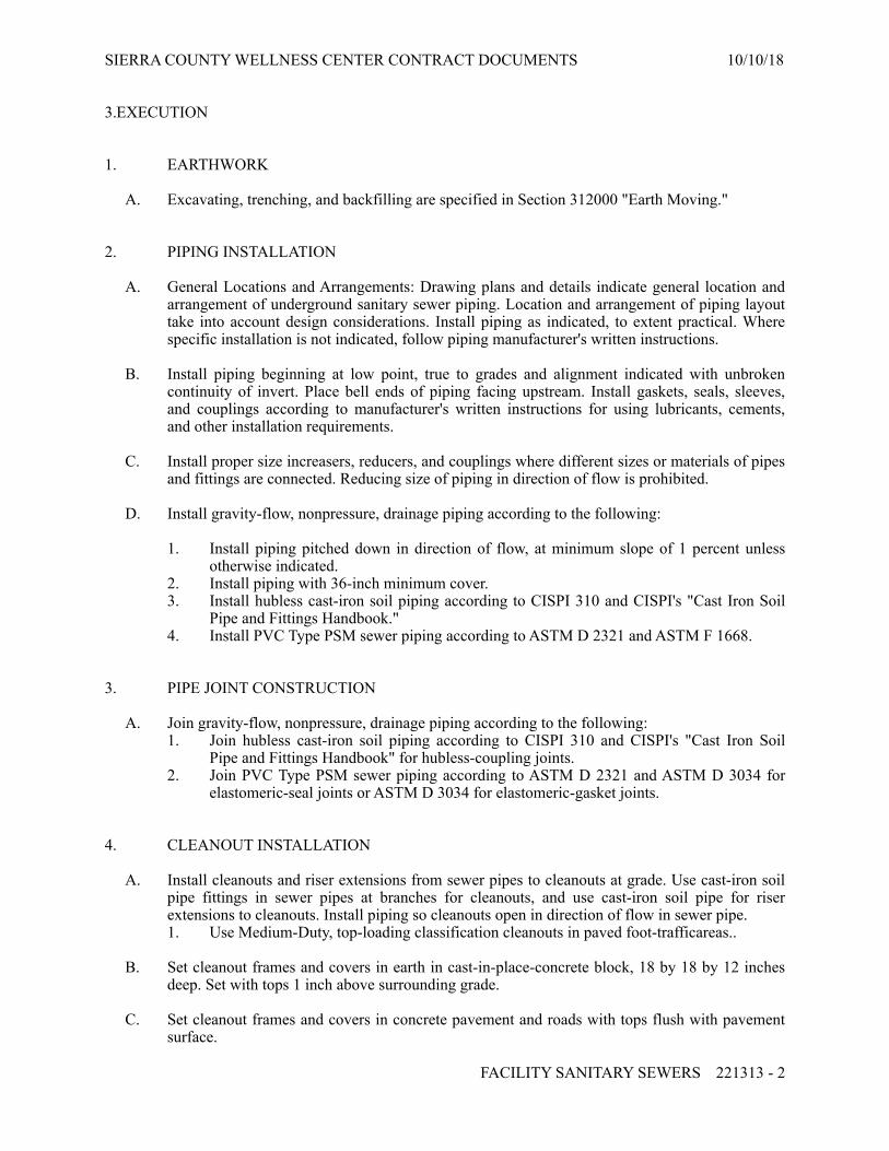
SIERRA COUNTY WELLNESS CENTER CONTRACT DOCUMENTS 10/10/18
3.EXECUTION
1. EARTHWORK
A. Excavating, trenching, and backfilling are specified in Section 312000 "Earth Moving."
2. PIPING INSTALLATION
A. General Locations and Arrangements: Drawing plans and details indicate general location and arrangement of underground sanitary sewer piping. Location and arrangement of piping layout take into account design considerations. Install piping as indicated, to extent practical. Where specific installation is not indicated, follow piping manufacturer's written instructions.
B. Install piping beginning at low point, true to grades and alignment indicated with unbroken continuity of invert. Place bell ends of piping facing upstream. Install gaskets, seals, sleeves, and couplings according to manufacturer's written instructions for using lubricants, cements, and other installation requirements.
C. Install proper size increasers, reducers, and couplings where different sizes or materials of pipes and fittings are connected. Reducing size of piping in direction of flow is prohibited.
D. Install gravity-flow, nonpressure, drainage piping according to the following:
1. Install piping pitched down in direction of flow, at minimum slope of 1 percent unless otherwise indicated.
2. Install piping with 36-inch minimum cover. 3. Install hubless cast-iron soil piping according to CISPI 310 and CISPI's "Cast Iron Soil
Pipe and Fittings Handbook." 4. Install PVC Type PSM sewer piping according to ASTM D 2321 and ASTM F 1668.
3. PIPE JOINT CONSTRUCTION
A. Join gravity-flow, nonpressure, drainage piping according to the following: 1. Join hubless cast-iron soil piping according to CISPI 310 and CISPI's "Cast Iron Soil
Pipe and Fittings Handbook" for hubless-coupling joints. 2. Join PVC Type PSM sewer piping according to ASTM D 2321 and ASTM D 3034 for
elastomeric-seal joints or ASTM D 3034 for elastomeric-gasket joints.
4. CLEANOUT INSTALLATION
A. Install cleanouts and riser extensions from sewer pipes to cleanouts at grade. Use cast-iron soil pipe fittings in sewer pipes at branches for cleanouts, and use cast-iron soil pipe for riser extensions to cleanouts. Install piping so cleanouts open in direction of flow in sewer pipe. 1. Use Medium-Duty, top-loading classification cleanouts in paved foot-trafficareas..
B. Set cleanout frames and covers in earth in cast-in-place-concrete block, 18 by 18 by 12 inches deep. Set with tops 1 inch above surrounding grade.
C. Set cleanout frames and covers in concrete pavement and roads with tops flush with pavement surface.
FACILITY SANITARY SEWERS 221313 - ! 2

SIERRA COUNTY WELLNESS CENTER CONTRACT DOCUMENTS 10/10/18
5. CONNECTIONS
A. Connect nonpressure, gravity-flow drainage piping to building's sanitary building drains specified in Section 221316 "Sanitary Waste and Vent Piping."
B. Make connections to existing piping and underground manholes.
1. Use commercially manufactured wye fittings for piping branch connections. Remove section of existing pipe, install wye fitting into existing piping. Protect existing piping and manholes to prevent concrete or debris from entering while making tap connections. Remove debris or other extraneous material that may accumulate.
6. FIELD QUALITY CONTROL
A. Test new piping systems, and parts of existing systems that have been altered, extended, or repaired, for leaks and defects.
1. Do not enclose, cover, or put into service before inspection and approval. 2. Test completed piping systems according to requirements of authorities having
jurisdiction. 3. Schedule tests and inspections by authorities having jurisdiction with at least 24 hours'
advance notice. 4. Hydrostatic Tests: Test sanitary sewerage according to requirements of authorities having
jurisdiction and the following:
a. Fill sewer piping with water. Test with pressure of at least 10-foot (3-m) head of water, and maintain such pressure without leakage for at least 15 minutes.
b. Close openings in system and fill with water. c. Purge air and refill with water. d. Disconnect water supply. e. Test and inspect joints for leaks.
B. Leaks and loss in test pressure constitute defects that must be repaired.
C. Replace leaking piping using new materials, and repeat testing until leakage is within allowances specified.
7. CLEANING
A. Clean dirt and superfluous material from interior of piping.
END OF SECTION 221313
FACILITY SANITARY SEWERS 221313 - ! 3

SIERRA COUNTY WELLNESS CENTER CONTRACT DOCUMENTS 10/10/18
SECTION 224100 - RESIDENTIAL PLUMBING FIXTURES
1.GENERAL
1. SUMMARY
A. Section Includes:. 1. Faucets. 2. Lavatories. 3. Showers. 4. Kitchen sinks. 5. Laundry trays. 6. Dishwasher air-gap fittings. 7. Disposers. 8. Water closets. 9. Toilet seats. 10. Supply fittings. 11. Waste fittings.
2. ACTION SUBMITTALS
A. Product Data: For each type of product.
3. INFORMATIONAL SUBMITTALS
A. Coordination Drawings: Counter cutout templates for mounting of counter-mounted plumbing fixtures.
4. CLOSEOUT SUBMITTALS
A. Maintenance data.
2.PRODUCTS: as indicated on drawings or as listed below:
1. DISHWASHER AIR-GAP FITTINGS
A. Dishwasher Air-Gap Fittings: 1. Description: Device designed to prevent backflow of contaminated liquid into domestic
dishwashers. 2. Material: Plastic bodywith chrome-plated-brass cover. 3. Hose Connections: 5/8-inch-ID inlet and 7/8-inch- ID outlet. 4. Capacity: At least 5 gpm; at inlet pressure of at least 5 psig and at temperature of at least
140 deg F). 5. Mounting: Deck. 6. Hoses: Rubber and suitable for temperature of at least 140 deg F.
RESIDENTIAL PLUMBING FIXTURES 224100 - ! 1

SIERRA COUNTY WELLNESS CENTER CONTRACT DOCUMENTS 10/10/18
2. DISPOSERS
A. Disposers: Continuous-feed household, food waste. 1. General: Include reset button; wall switch; corrosion-resistant chamber with jam-
resistant, cutlery- or stainless-steel grinder or shredder; NPS 1-1/2 outlet; quick-mounting, stainless-steel sink flange; antisplash guard; and combination cover/stopper.
2. Model: as indicated on drawings.
3. TOILET SEATS
A. Toilet Seats: 1. Standard: IAPMO/ANSI Z124.5. 2. Material: Plastic. 3. Type: Standard. 4. Shape: Elongated rim Closed front.. 5. Hinge Type: Self-sustaining, check. 6. Hinge Material: Noncorroding metal. 7. Seat Cover: Required. 8. Color: White.
4. SUPPLY FITTINGS
A. NSF Standard: Comply with NSF/ANSI 61 Annex G, "Drinking Water System Components - Health Effects," for faucet materials that will be in contact with potable water.
B. Standard: ASME A112.18.1/CSA B125.1.
C. Lavatory, Kitchen Sink, and Laundry Tray Supply Fittings:
1. Supply Piping: Chrome-plated-brass pipe or chrome-plated-copper tube matching water-supply piping size. Include chrome-plated wall flange.
2. Stops: Chrome-plated-brass, one-quarter-turn, ball-type or compression stop with inlet connection matching water-supply piping type and size.
3. Risers:
a. Size: NPS 3/8 for lavatories. b. Size: NPS 1/2 for kitchen sinks and laundry trays. c. Material: ASME A112.18.6, braided or corrugated-stainless-steel flexible hose
riser.
5. WASTE FITTINGS
A. Standard: ASME A112.18.2/CSA B125.2.
B. Drain: Grid type with NPS 1-1/4 offset tailpiece for accessible lavatories.
C. Drain: Grid type with NPS 1-1/2 offset tailpiece for accessible kitchen sinks.
D. Drain: Grid type with NPS 1-1/2 straight tailpiece for standard laundry trays.
RESIDENTIAL PLUMBING FIXTURES 224100 - ! 2

SIERRA COUNTY WELLNESS CENTER CONTRACT DOCUMENTS 10/10/18
E. Trap:
1. Size: NPS 1-1/4 for lavatories. 2. Size: NPS 1-1/2 for kitchen sinks and laundry trays. 3. Material: Chrome-plated, two-piece, cast-brass trap and swivel elbow with 0.032-inch-
thick brass tube to wall.
3.EXECUTION
1. INSTALLATION
A. Install plumbing fixtures level and plumb according to roughing-in drawings.
B. Install floor-mounted water closets on closet flange attachments to drainage piping.
C. Install counter-mounting fixtures in and attached to casework.
D. Install wall mount lavatories on iron supports and secured to wood blocking in wall.
E. Install water-supply piping with stop on each supply to each fixture to be connected to water distribution piping. Attach supplies to supports or substrate within pipe spaces behind fixtures. Install stops in locations where they can be easily reached for operation.
1. Exception: Use ball or gate valves if supply stops are not specified with fixture. Comply with valve requirements specified in Section 220523.12 "Ball Valves for Plumbing Piping" and Section 220523.15 "Gate Valves for Plumbing Piping."
F. Install tanks for accessible, tank-type water closets with lever handle mounted on wide side of compartment.
G. Install toilet seats on water closets.
H. Install faucet flow-control fittings with specified flow rates and patterns in faucet spouts if faucets are not available with required rates and patterns. Include adapters if required.
I. Install shower flow-control fittings with specified maximum flow rates in shower arms.
J. Install traps on fixture outlets.
1. Exception: Omit trap on fixtures with integral traps. 2. Exception: Omit trap on indirect wastes unless otherwise indicated.
K. Install disposer in outlet of each sink indicated to have disposer. Install switch where indicated or in wall adjacent to sink if location is not indicated.
L. Install dishwasher air-gap fitting at each sink indicated to have air-gap fitting. Install in sink deck. Connect inlet hose to dishwasher and outlet hose to disposer.
M. Set shower receptors in leveling bed of cement grout.
N. Install protective shielding pipe covers, insulation, and enclosures on exposed supplies and waste piping of accessible lavatories and sinks.
RESIDENTIAL PLUMBING FIXTURES 224100 - ! 3

SIERRA COUNTY WELLNESS CENTER CONTRACT DOCUMENTS 10/10/18
O. Install wall flanges or escutcheons at piping wall penetrations in exposed, finished locations. Use deep-pattern escutcheons if required to conceal protruding fittings. Comply with escutcheon requirements specified in Section 220518 "Escutcheons for Plumbing Piping."
P. Seal joints between plumbing fixtures, counters, floors, and walls using sanitary-type, one-part, mildew-resistant silicone sealant. Match sealant color to fixture color. Comply with sealant requirements specified in Section 079200 "Joint Sealants."
2. CONNECTIONS
A. Connect fixtures with water supplies, stops, and risers, and with traps, soil, waste, and vent piping. Use size fittings required to match fixtures.
3. ADJUSTING
A. Operate and adjust plumbing fixtures and controls. Replace damaged and malfunctioning fixtures, fittings, and controls.
B. Adjust water pressure at faucets to produce proper flow.
4. CLEANING AND PROTECTION
A. After completing installation of plumbing fixtures, inspect and repair damaged finishes.
B. Clean plumbing fixtures, faucets, and other fittings with manufacturers' recommended cleaning methods and materials.
C. Provide protective covering for installed plumbing fixtures and fittings.
D. Do not allow use of plumbing fixtures for temporary facilities unless approved in writing by Owner.
END OF SECTION 224100
RESIDENTIAL PLUMBING FIXTURES 224100 - ! 4

SIERRA COUNTY WELLNESS CENTER CONTRACT DOCUMENTS 10/10/18
SECTION 312000 - EARTH MOVING
1.GENERAL
1. SUMMARY
A. Section Includes:
1. Excavating and filling for rough grading the Site. 2. Preparing subgrades for slabs-on-grade, and walks. 3. Excavating and backfilling for buildings and structures. 4. Subbase course for concrete walks. 5. Excavating and backfilling trenches for utilities and pits for buried utility structures.
2. DEFINITIONS
A. Backfill: Soil material used to fill an excavation.
1. Initial Backfill: Backfill placed beside and over pipe in a trench, including haunches to support sides of pipe.
2. Final Backfill: Backfill placed over initial backfill to fill a trench.
B. Bedding Course: Aggregate layer placed over the excavated subgrade in a trench before laying pipe.
C. Borrow Soil: Satisfactory soil imported from off-site for use as fill or backfill.
D. Drainage Course: Aggregate layer supporting the slab-on-grade that also minimizes upward capillary flow of pore water.
E. Excavation: Removal of material encountered above subgrade elevations and to lines and dimensions indicated.
1. Authorized Additional Excavation: Excavation below subgrade elevations or beyond indicated lines and dimensions as directed by Architect. Authorized additional excavation and replacement material will be paid for according to Contract provisions for changes in the Work.
2. Unauthorized Excavation: Excavation below subgrade elevations or beyond indicated lines and dimensions without direction by Architect. Unauthorized excavation, as well as remedial work directed by Architect, shall be without additional compensation.
F. Fill: Soil materials used to raise existing grades.
G. Structures: Buildings, footings, foundations, retaining walls, slabs, tanks, curbs, mechanical and electrical appurtenances, or other man-made stationary features constructed above or below the ground surface.
H. Subbase Course: Aggregate layer placed between the subgrade and base course for hot-mix asphalt pavement, or aggregate layer placed between the subgrade and a cement concrete pavement or a cement concrete or hot-mix asphalt walk.
EARTH MOVING 312000 - ! 1

SIERRA COUNTY WELLNESS CENTER CONTRACT DOCUMENTS 10/10/18
I. Subgrade: Uppermost surface of an excavation or the top surface of a fill or backfill immediately below subbase, drainage fill, drainage course, or topsoil materials.
J. Utilities: On-site underground pipes, conduits, ducts, and cables as well as underground services within buildings.
3. PREINSTALLATION MEETINGS
A. Preinstallation Conference: Conduct pre-excavation conference at Project site.
4. FIELD CONDITIONS
A. Utility Locator Service: Notify utility locator service for area where Project is located before beginning earth-moving operations.
2. PRODUCTS
1. SOIL MATERIALS
A. General: Provide borrow soil materials when sufficient satisfactory soil materials are not available from excavations.
B. Subbase Material: Naturally or artificially graded mixture of natural or crushed gravel, crushed stone, and natural or crushed sand; ASTM D 2940/D 2940M; with at least 90 percent passing a 1-1/2-inch sieve and not more than 12 percent passing a No. 200 sieve.
2. ACCESSORIES
A. Warning Tape: Acid- and alkali-resistant, polyethylene film warning tape manufactured for marking and identifying underground utilities, 6 inches (150 mm) wide and 4 mils (0.1 mm) thick, continuously inscribed with a description of the utility; colored to comply with local practice or requirements of authorities having jurisdiction.
B. Detectable Warning Tape: Acid- and alkali-resistant, polyethylene film warning tape manufactured for marking and identifying underground utilities, a minimum of 6 inches (150 mm) wide and 4 mils (0.1 mm) thick, continuously inscribed with a description of the utility, with metallic core encased in a protective jacket for corrosion protection, detectable by metal detector when tape is buried up to 30 inches (750 mm) deep; colored to comply with local practice or requirements of authorities having jurisdiction.
3.EXECUTION
1. PREPARATION
A. Protect structures, utilities, sidewalks, pavements, and other facilities from damage caused by settlement, lateral movement, undermining, washout, and other hazards created by earth-moving operations.
EARTH MOVING 312000 - ! 2

SIERRA COUNTY WELLNESS CENTER CONTRACT DOCUMENTS 10/10/18
B. Protect and maintain erosion and sedimentation controls during earth-moving operations.
C. Protect subgrades and foundation soils from freezing temperatures and frost. Remove temporary protection before placing subsequent materials.
2. EXCAVATION, GENERAL
A. Unclassified Excavation: Excavate to subgrade elevations regardless of the character of surface and subsurface conditions encountered. Unclassified excavated materials may include rock, soil materials, and obstructions. No changes in the Contract Sum or the Contract Time will be authorized for rock excavation or removal of obstructions.
1. If excavated materials intended for fill and backfill include unsatisfactory soil materials and rock, replace with satisfactory soil materials.
3. EXCAVATION FOR STRUCTURES
A. Excavate to indicated elevations and dimensions within a tolerance of plus or minus 1 inch. If applicable, extend excavations a sufficient distance from structures for placing and removing concrete formwork, for installing services and other construction, and for inspections.
1. Excavations for Footings and Foundations: Do not disturb bottom of excavation. Excavate by hand to final grade just before placing concrete reinforcement. Trim bottoms to required lines and grades to leave solid base to receive other work.
4. EXCAVATION FOR WALKS AND PAVEMENTS
A. Excavate surfaces under walks and pavements to indicated lines, cross sections, elevations, and subgrades.
5. EXCAVATION FOR UTILITY TRENCHES
A. Excavate trenches to indicated gradients, lines, depths, and elevations.
B. Excavate trenches to uniform widths to provide the following clearance on each side of pipe or conduit. Excavate trench walls vertically from trench bottom to 12 inches higher than top of pipe or conduit unless otherwise indicated.
1. Clearance: 12 inches each side of pipe or conduit.
C. Trench Bottoms: Excavate and shape trench bottoms to provide uniform bearing and support of pipes and conduit. Shape subgrade to provide continuous support for bells, joints, and barrels of pipes and for joints, fittings, and bodies of conduits. Remove projecting stones and sharp objects along trench subgrade.
1. Excavate trenches 6 inches deeper than elevation required in rock or other unyielding bearing material to allow for bedding course.
EARTH MOVING 312000 - ! 3

SIERRA COUNTY WELLNESS CENTER CONTRACT DOCUMENTS 10/10/18
6. UNAUTHORIZED EXCAVATION
A. Fill unauthorized excavation under foundations or wall footings by extending bottom elevation of concrete foundation or footing to excavation bottom, without altering top elevation. Lean concrete fill, with 28-day compressive strength of 2500 psi, may be used when approved by Architect.
1. Fill unauthorized excavations under other construction, pipe, or conduit as directed by Architect.
7. UTILITY TRENCH BACKFILL
A. Place backfill on subgrades free of mud, frost, snow, or ice.
B. Place and compact bedding course on trench bottoms and where indicated. Shape bedding course to provide continuous support for bells, joints, and barrels of pipes and for joints, fittings, and bodies of conduits.
C. Trenches under Footings: Backfill trenches excavated under footings and within 18 inches of bottom of footings with satisfactory soil; fill with concrete to elevation of bottom of footings.
D. Initial Backfill: Place and compact initial backfill of satisfactory soil, free of particles larger than 2 inches in any dimension, to a height of 12 inches (300 mm) over the pipe or conduit.
1. Carefully compact initial backfill under pipe haunches and compact evenly up on both sides and along the full length of piping or conduit to avoid damage or displacement of piping or conduit. Coordinate backfilling with utilities testing.
E. Final Backfill: Place and compact final backfill of satisfactory soil to final subgrade elevation.
F. Warning Tape: Install warning tape directly above utilities, 12 inches (300 mm) below finished grade, except 6 inches below subgrade under pavements and slabs.
8. SOIL FILL
A. Plow, scarify, bench, or break up sloped surfaces steeper than 1 vertical to 4 horizontal so fill material will bond with existing material.
B. Place and compact fill material in layers to required elevations as follows: 1. Under walks and pavements, use satisfactory soil material. 2. Under steps and ramps, use engineered fill. 3. Under footings and foundations, use engineered fill.
9. SOIL MOISTURE CONTROL
A. Uniformly moisten or aerate subgrade and each subsequent fill or backfill soil layer before compaction to within 2 percent of optimum moisture content.
1. Do not place backfill or fill soil material on surfaces that are muddy, frozen, or contain frost or ice.
EARTH MOVING 312000 - ! 4

SIERRA COUNTY WELLNESS CENTER CONTRACT DOCUMENTS 10/10/18
2. Remove and replace, or scarify and air dry, otherwise satisfactory soil material that exceeds optimum moisture content by 2 percent and is too wet to compact to specified dry unit weight.
10. COMPACTION OF SOIL BACKFILLS AND FILLS
A. Place backfill and fill soil materials in layers not more than 8 inches in loose depth for material compacted by heavy compaction equipment and not more than 4 inches in loose depth for material compacted by hand-operated tampers.
B. Place backfill and fill soil materials evenly on all sides of structures to required elevations and uniformly along the full length of each structure.
C. Compact soil materials to not less than the following percentages of maximum dry unit weight according to ASTM D 698: 1. Under walkways, compact top 6 inches below subgrade and compact each layer of
backfill or fill soil material at 90 percent. 2. For utility trenches, compact each layer of initial and final backfill soil material at 85
percent.
11. SUBBASE AND BASE COURSES UNDER PAVEMENTS AND WALKS
A. Place base course on subgrades free of mud, frost, snow, or ice.
B. On prepared subgrade, place base course under pavements and walks as follows:
1. Shape base course] to required crown elevations and cross-slope grades. 2. Place base course that exceeds 6 inches (150 mm) in compacted thickness in layers of
equal thickness, with no compacted layer more than 6 inches (150 mm) thick or less than 3 inches (75 mm) thick.
3. Compact base course] at optimum moisture content to required grades, lines, cross sections, and thickness to not less than 90percent of maximum dry unit weight according to ASTM D 698..
12. FIELD QUALITY CONTROL
A. Testing Agency: Owner will engage a qualified geotechnical engineering testing agency to perform tests and inspections.
B. Allow testing agency to inspect and test subgrades and each fill or backfill layer. Proceed with subsequent earth moving only after test results for previously completed work comply with requirements.
C. When testing agency reports that subgrades, fills, or backfills have not achieved degree of compaction specified, scarify and moisten or aerate, or remove and replace soil materials to depth required; recompact and retest until specified compaction is obtained.
EARTH MOVING 312000 - ! 5

SIERRA COUNTY WELLNESS CENTER CONTRACT DOCUMENTS 10/10/18
13. DISPOSAL OF SURPLUS AND WASTE MATERIALS
A. Remove surplus satisfactory soil and waste materials, including unsatisfactory soil, trash, and debris, and legally dispose of them off Owner's property.
END OF SECTION 312000
EARTH MOVING 312000 - ! 6

SIERRA COUNTY WELLNESS CENTER CONTRACT DOCUMENTS 10/10/18
SECTION 321313 - CONCRETE PAVING
1.GENERAL
1. SUMMARY
A. Section Includes Concrete Paving Including the Following: 1. Walks. 2. Ramps 3. Porches
2. ACTION SUBMITTALS
A. Design Mixtures: For each concrete paving mixture. Include alternate design mixtures when characteristics of materials, Project conditions, weather, test results, or other circumstances warrant adjustments.
2.PRODUCTS
1. CONCRETE, GENERAL
A. ACI Publications: Comply with ACI 301 unless otherwise indicated.
2. STEEL REINFORCEMENT
A. Recycled Content: Postconsumer recycled content plus one-half of preconsumer recycled content not less than 25 percent.
B. Plain-Steel Welded-Wire Reinforcement: ASTM A 1064/A 1064M, fabricated from as-drawn steel wire into flat sheets.
C. Deformed-Steel Welded-Wire Reinforcement: ASTM A 1064/A 1064M, flat sheet.
D. Reinforcing Bars: ASTM A 615/A 615M, Grade 60; deformed.
E. Joint Dowel Bars: ASTM A 615/A 615M, Grade 60 plain-steel bars. Cut bars true to length with ends square and free of burrs.
F. Bar Supports: Bolsters, chairs, spacers, and other devices for spacing, supporting, and fastening reinforcing bars, welded-wire reinforcement, and dowels in place. Manufacture bar supports according to CRSI's "Manual of Standard Practice" from steel wire, plastic, or precast concrete of greater compressive strength than concrete specified.
3. CONCRETE MATERIALS
A. Cementitious Materials: Use the following cementitious materials, of same type, brand, and source throughout Project:
CONCRETE PAVING 321313 - ! 1

SIERRA COUNTY WELLNESS CENTER CONTRACT DOCUMENTS 10/10/18
B. Normal-Weight Aggregates: ASTM C 33/C 33M, Class 4S, uniformly graded. Provide aggregates from a single source.
C. Air-Entraining Admixture: ASTM C 260/C 260M.
D. Chemical Admixtures: Admixtures certified by manufacturer to be compatible with other admixtures and to contain not more than 0.1 percent water-soluble chloride ions by mass of cementitious material.
E. Water: Potable and complying with ASTM C 94/C 94M.
4. CURING MATERIALS.
A. Moisture-Retaining Cover: ASTM C 171, polyethylene film or white burlap-polyethylene sheet.
B. Water: Potable.
C. Evaporation Retarder: Waterborne, monomolecular, film forming, manufactured for application to fresh concrete.
D. Clear, Waterborne, Membrane-Forming Curing Compound: ASTM C 309, Type 1, Class B, dissipating.
5. RELATED MATERIALS
A. Joint Fillers: ASTM D 1751, asphalt-saturated cellulosic fiber in preformed strips.
6. CONCRETE MIXTURES
A. Prepare design mixtures, proportioned according to ACI 301, for each type and strength of normal-weight concrete, and as determined by either laboratory trial mixtures or field experience.
B. Cementitious Materials:[ Use fly ash, pozzolan, slag cement, and silica fume as needed to reduce the total amount of portland cement, which would otherwise be used, by not less than 25 percent. Limit percentage, by weight, of cementitious materials other than portland cement in concrete as follows:
1. Fly Ash or Pozzolan: 15 percent. 2. Slag Cement: 40 percent. 3. Combined Fly Ash or Pozzolan, and Slag Cement: 50 percent, with fly ash or pozzolan
not exceeding 15 percent.
C. Chemical Admixtures: Use admixtures according to manufacturer's written instructions.
D. Concrete Mixtures: Normal-weight concrete.
1. Compressive Strength (28 Days): 2,500 psi. 2. Maximum W/C Ratio at Point of Placement: 0.50. 3. Slump Limit: 5 inches, plus or minus 1 inch. 4. Solar Reflectance Index: Not less than 29.
CONCRETE PAVING 321313 - ! 2

SIERRA COUNTY WELLNESS CENTER CONTRACT DOCUMENTS 10/10/18
7. CONCRETE MIXING
A. Ready-Mixed Concrete: Measure, batch, and mix concrete materials and concrete according to ASTM C 94/C 94M[ and ASTM C 1116/C 1116M]. Furnish batch certificates for each batch discharged and used in the Work.
3.EXECUTION
1. EXAMINATION
A. Proof-roll prepared subbase surface below concrete paving to identify soft pockets and areas of excess yielding.
2. PREPARATION
A. Remove loose material from compacted subbase surface immediately before placing concrete.
3. EDGE FORMS AND SCREED CONSTRUCTION
A. Set, brace, and secure edge forms, bulkheads, and intermediate screed guides to required lines, grades, and elevations. Install forms to allow continuous progress of work and so forms can remain in place at least 24 hours after concrete placement.
B. Clean forms after each use and coat with form-release agent to ensure separation from concrete without damage.
4. STEEL REINFORCEMENT INSTALLATION
A. Comply with CRSI's "Manual of Standard Practice" for fabricating, placing, and supporting reinforcement.
5. JOINTS
A. General: Form construction, isolation, and contraction joints and tool edges true to line, with faces perpendicular to surface plane of concrete. Construct transverse joints at right angles to centerline unless otherwise indicated.
B. Construction Joints: Set construction joints at side and end terminations of paving and at locations where paving operations are stopped for more than one-half hour unless paving terminates at isolation joints.
C. Isolation Joints: Form isolation joints of preformed joint-filler strips abutting concrete curbs, catch basins, manholes, inlets, structures, other fixed objects, and where indicated.
D. Contraction Joints: Form weakened-plane contraction joints, sectioning concrete into areas as indicated. Construct contraction joints for a depth equal to at least one-fourth of the concrete thickness[, to match jointing of existing adjacent concrete paving]:
CONCRETE PAVING 321313 - ! 3

SIERRA COUNTY WELLNESS CENTER CONTRACT DOCUMENTS 10/10/18
E. Edging: After initial floating, tool edges of paving, gutters, curbs, and joints in concrete with an edging tool to a 3/8-inch radius. Repeat tooling of edges after applying surface finishes.
6. CONCRETE PLACEMENT
A. Moisten subbase to provide a uniform dampened condition at time concrete is placed. Do not place concrete around manholes or other structures until they are at required finish elevation and alignment.
B. Comply with ACI 301 (ACI 301M) requirements for measuring, mixing, transporting, and placing concrete.
C. Deposit and spread concrete in a continuous operation between transverse joints. Do not push or drag concrete into place or use vibrators to move concrete into place.
D. Screed paving surface with a straightedge and strike off.
E. Commence initial floating using bull floats or darbies to impart an open-textured and uniform surface plane before excess moisture or bleedwater appears on the surface. Do not further disturb concrete surfaces before beginning finishing operations or spreading surface treatments.
7. FLOAT FINISHING
A. General: Do not add water to concrete surfaces during finishing operations.
B. Float Finish: Begin the second floating operation when bleedwater sheen has disappeared and concrete surface has stiffened sufficiently to permit operations. Float surface with power-driven floats or by hand floating if area is small or inaccessible to power units. Finish surfaces to true planes. Cut down high spots and fill low spots. Refloat surface immediately to uniform granular texture.
1. Medium Broom Finish: Draw a soft-bristle broom across float-finished concrete surface, perpendicular to line of traffic, to provide a uniform, fine-line texture.
8. CONCRETE PROTECTION AND CURING
A. General: Protect freshly placed concrete from premature drying and excessive cold or hot temperatures.
B. Comply with ACI 306.1 for cold-weather protection..
9. PAVING TOLERANCES
A. Comply with tolerances in ACI 117 and as follows:
1. Elevation: 3/4 inch. 2. Thickness: Plus 3/8 inch, minus 1/4 inch. 3. Surface: Gap below 10-feet- long; unleveled straightedge not to exceed 1/2 inch. 4. Joint Spacing: 3 inches.
CONCRETE PAVING 321313 - ! 4

SIERRA COUNTY WELLNESS CENTER CONTRACT DOCUMENTS 10/10/18
5. Contraction Joint Depth: Plus 1/4 inch, no minus. 6. Joint Width: Plus 1/8 inch, no minus.
10. REPAIR AND PROTECTION
A. Remove and replace concrete paving that is broken, damaged, or defective or that does not comply with requirements in this Section. Remove work in complete sections from joint to joint unless otherwise approved by Architect.
B. Protect concrete paving from damage. Exclude traffic from paving for at least 14 days after placement. When construction traffic is permitted, maintain paving as clean as possible by removing surface stains and spillage of materials as they occur.
C. Maintain concrete paving free of stains, discoloration, dirt, and other foreign material. Sweep paving not more than two days before date scheduled for Substantial Completion inspections.
END OF SECTION 321313
CONCRETE PAVING 321313 - ! 5