© asme cc-by
TRANSCRIPT

Research SpaceJournal article
A portable elbow exoskeleton for three stages of rehabilitation
Manna, S. and Dubey, V. N.
© ASME
CC-BY

1
A Portable Elbow Exoskeleton for Three Stages of Rehabilitation 1 2
3 Soumya K Manna, Venketesh N. Dubey 4
Faculty of Science and Technology, Bournemouth University 5 Talbot Campus, Poole, BH12 5BB, United Kingdom 6
7 Abstract: Patients suffering from stroke need to undergo a standard and intensive rehabilitation 8 therapy. The rehabilitation training consists of three sequential stages; the first stage is controlled 9 joint movement under external actuator, the second stage deals with supporting the movements by 10 providing assistive force and the last stage provides variety and difficulty to exercises. Most of the 11 exoskeletons developed so far for rehabilitation are restricted to a particular type of activity. 12 Although a few exoskeletons incorporate different modes of rehabilitation, those are software 13 controlled requiring sensory data acquisition and complex control architecture. To bridge this gap, a 14 portable elbow exoskeleton has been developed for delivering three stages of rehabilitation in a 15 single structure without affecting the range of motion and safety features. Use of electric motor and 16 springs have been arranged in the actuation mechanism to minimise the energy consumption. The 17 developed exoskeleton enhances torque to weight ratio compared to existing models and all three 18 modes of rehabilitation have been controlled using a single motor. 19 20 Keywords: Exoskeleton, Rehabilitation, Portable, Stiffness control, Gravity compensation, Stroke. 21 22 1. Introduction 23 Present statistics shows that there are about 33 million stroke survivors worldwide [1]. The annual 24 health and social costs of caring for disabled stroke patients are estimated to be in excess of £5 25 billion in the UK alone [2]. To reduce the burden of manual therapy which includes unavailability of 26 sufficient number of caregivers and intensity of exercises, exoskeleton based rehabilitation has 27 become a promising alternative [3]. However, the majority of developed exoskeletons can provide 28 only a specific type of exercise [4]. A few standard rehabilitation processes are followed from acute 29 stage to full recovery stage after stroke [5], [6], [7]. All these stages are used to regain the controlled 30 muscle movement by reducing spasticity and involuntary movement. After analysing the function 31 and treatment procedure of each stage, these can be categorized into three distinct stages as shown in 32 Fig. 1. These are actuator based joint control, supportive force and resistive force. 33
34 Figure 1. Three phases of rehabilitation for post-stroke patients 35
If exercise is performed in transverse plane using exoskeleton, patients only need to overcome the 36 frictional force of the exoskeleton structure. If the same exercise is performed in sagittal plane, the 37

2
exoskeleton requires higher joint torque to carry out the load against gravity; size of the actuator as 38 well as the actuation system needs to be effective to obtain the required torque. The range of 39 movement is improved if exercises were performed in gravity compensated training environment [8]. 40 Postural stability is achieved by active holding of the body segment against external force [9]. 41 Even after three decades of research, no standard solution has been presented for the design of 42 exoskeleton to provide the best rehabilitation therapy [10]. Most of the exoskeletons have focused on 43 design aspect which includes portability and user-friendliness but failing on providing the standard 44 rehabilitation training. Two essential factors can be considered for the design of exoskeletons; one is 45 its mechanical design and other is the rehabilitation therapy. 46 The quality of rehabilitation therapy using exoskeleton can be improved by introducing three stages 47 of rehabilitation in a single structure which can possibly be accomplished in two ways; one is the 48 hardware-based solution and the other is software approach. In software approach [11], actuator used 49 in the exoskeleton can provide three stages of therapy using adaptive control algorithms. In order to 50 execute patient-oriented exercises using external actuators, electric motors are normally placed at the 51 joint of most exoskeletons [12]. Here different bio-sensors attached to user send signals to the 52 control system about the patient’s intention and the motors provide assistive or resistive torque to the 53 affected joint as per the signal received from biosensors (EMG, EEG). Because of the reliance on 54 biosignals, those systems are inoperable without sensors. Movement based on EMG data extraction 55 from stroke patients is difficult because of abnormal EMG-torque relationship [13]. The adaptive 56 control algorithm used in exoskeleton results in constant draining of energy for controlling the 57 variable joint torque and active range of motion. Also, the adaptive control system always takes over 58 the control by making patients inactive which indirectly reduces their activities during training [14], 59 therefore diminishes the rehabilitation effectiveness. Joint-based actuation system also requires 60 higher torque compared to the designs where joint is remotely controlled. To carry out the exercises 61 with higher load, size and weight of the motor are also increased [15] and so is the cost. As a result, 62 most of the electric motor controlled exoskeletons are ground-based system [16]. In the former case, 63 human joint is always under motor control which might not be ideal from safety point of view. If the 64 joint moves beyond the anatomical range, it may cause injury. Looking at these limitations, a 65 hardware-based solution may provide viable option for user acceptance. 66 Integration of multistage rehabilitation can be achieved using active and passive components in the 67 mechanism which can reduce the complexity of the control system. For example, a system can use 68 an electromagnetic clutch/brake for shifting from one rehabilitation mode to another though it will 69 drain energy and create unwanted noise during switching. Passive actuation systems use elastic 70 elements such as spring or rubber band which can provide the required joint torque for reducing the 71 gravity force during elbow movement. Such spring-based exoskeletons [17],[18] do not need any 72 energy source to actuate but these systems can only provide assistive force to users. The back-73 drivable motor in combination with a series elastic actuator [19] is also able to provide both types of 74 rehabilitation, however if the back-drivability is too low, the gearbox can be damaged due to sudden 75 external force. Compliant mechanism [20] can provide variable stiffness to the joint however, it can 76 only generate resistive force. 77 Hence it is quite challenging to integrate all types of exercise in a single exoskeleton because 78 exercises involved in the three stages after stroke are totally different in nature. In acute stage, 79 patients require fixed contact to human arm because they have no power left to move their arm but in 80 rest of the recovery stages, exoskeleton needs a compliant contact to allow them to carry out the 81 exercises themselves. The aim of this paper is to create an innovative joint mechanism for the 82 exoskeleton to achieve both these properties without any extra burden to system or risk to the users. 83 The novelty of the developed exoskeleton can be described as: 84 • The developed exoskeleton delivers all modes of exercises (external force, assistive and resistive) 85
required for three stages of rehabilitation in a single structure. 86 • The exoskeleton mechanism generates variable assistive as well as resistive force without using 87
any complex control algorithms. 88

3
• Electric motor is used to control the joint whereas in rest of the two modes, joint motions are 89 supported by stiffness of the springs for providing assistive or resistive force. 90
• Spring stiffness is used for the switching mechanism to shift between rehabilitation modes, 91 therefore, no brakes or clutches are required making it an energy efficient mechanism. 92
• The switching mechanism supports safety of the users mechanically since joint control is 93 transferred from motor to user when the elbow joint goes beyond the permissible limit. 94
• To achieve all this a single motor has been used in the whole exoskeleton design. 95 96 2. Design description 97 The exoskeleton has been conceptualized as a mechanism where the whole operating region is 98 divided into three sub-regions to provide specific exercises as shown in Fig. 2. All these regions are 99 interconnected and will appear one after another mechanically. The type of exercise generated by 100 exoskeleton is aligned with the post-stroke recovery stages. The exoskeleton utilizes the motor 101 torque in acute phase when users do not have enough strength and provides spring energy during 102 self-movement for generating assistive and resistive force. A couple of springs (compression and 103 torsional) have been used in the exoskeleton for switching between different regions. The schematic 104 diagram of the exoskeleton and its 3D model are shown in Fig. 3 (a and b). 105 106
107 Figure 2. Operating region of the exoskeleton 108
109
(a) Schematic diagram 110

4
111 (b) 3D model 112
Figure 3. Exoskeleton Design 113
114 115 116 117 118 119 120 The relationship between the distance covered by the nut slider (x) and the motor rotations (n, θ) is 121 given by 122
𝑥 = 𝑛𝑛𝑛2𝜋𝜋
(1) 123
Where, n - Number of turns of the motor 124 θ - Angle made by the motor 125 L - Lead of the screw 126 N - Gear ratio for transferring the motion to the leadscrew (1.5:1) 127
Mode of rehabilitation: 0 ≤ 𝑥 ≤ 𝑥1 = Electric motor based joint control (0 to 0.18 m) 128 𝑥1 < 𝑥 ≤ 𝑥2 = Spring based assistive force (0.181 to 0.20 m) 129 𝑥2 < 𝑥 ≤ 𝑥3 = Spring based resistive force (0.201 to 0.24 m) 130
Where x1, x2, x3 are the switching positions. 131 132 2.1 Electric motor based joint control (first region) 133 In the first region, the electric motor controls the joint movement without any active participation 134 from the user. The actuation system has been designed based on a leadscrew in combination with a 135 slider-crank mechanism (Fig. 4). Motion from the motor is transferred to the leadscrew through 136 reduction gears. Slider-crank mechanism converts the linear motion of leadscrew into elbow joint 137 rotation. The leadscrew and slider crank mechanism are not directly coupled to each other. There are 138 two loads to overcome; one of which acts as a nut that translates in both directions on the screw and 139 the other slider moves over the leadscrew concentrically without being placed on the leadscrew. In 140 the first region (0<x≤x1), a spring (S6) actuates the locking mechanism that keeps both sliders in 141 contact as a single unit until the elbow joint rotates to its maximum anatomical limit (0-130o). 142 143
(1) Baseplate (7) Nut slider (13) Connecting link (2) Motor (8) Concentric slider (14) Universal joint (3) Gear (9) Elbow joint (15) Claw-type jaws (4) Solid rods (10) Revolute joint (16) Rectangular slider (5) Slider for variable stiffness (11) Compression spring (17) Connected plates (6) Leadscrew (12) Forearm supporting link (18) Small cylindrical rod

5
144 Figure 4. Electric motor based joint control 145
2.2 Switching from the electric motor control (first region) to assistive force (Second region) 146 In the locking mechanism, two claw-type jaws are connected to the nut slider in the form of a four-147 bar mechanism (Fig. 5(a), Locked condition). The locking condition remains enforced until the two 148 compression springs S5 and S6 clash with each other due to the backward movement of the nut slider. 149 As soon as the nut slider crosses the switching position (x>x1), switching takes place. Because of the 150 higher stiffness, the force exerted by S5 is greater than S6, thus a small displacement of S5 causes a 151 large displacement in S6. As a result, S6 will be compressed by the resultant force and both jaws will 152 rotate about a fixed point to free those sliders (see the unlocked condition, Fig. 5(b)). However, 153 forward movement of the nut slider beyond the switching point will restore the locking mechanism 154 again. The ratio of the stiffness of S5 and S6 has been determined in a way that the switching region 155 becomes as small as possible. 156
157 (a) Locked condition (b) Unlocked condition 158
Figure 5. Switching from motor based control to spring assisted force 159
After opening of the lock, the nut slider and concentric slider are detached from each other and the 160 joint rotation is not under electric motor control. In this phase, patients are free to control their own 161 movements and S2 provides assistive force to help rotate the elbow joint (Fig. 6). The joint is torque 162 balanced at every configuration due to the spring force and only a small effort is required from 163 patients for lifting up any load or the forearm loads against gravity. Higher assistive force reduces 164 the effort of users to reach a full joint rotation during flexion. The same assistive force opposes the 165 forearm freefall during extension. In this way, the assistive force balances the arm weight and slows 166 down the joint movement to achieve full extension. The assistive force during rehabilitation should 167 be adaptable for different load under gravity. The structural part of the exoskeleton to provide 168 variable gravity compensation consists of two torsional springs (S7 and S8), one compression spring 169 (S1), one small cylindrical rod (CR1), one small rectangular slider (SL1) and two rectangular plates 170 (RP1 and RP2). SL1 is concentric to CR1 which is attached to the base plate. The range of spring force 171 provided by S2 can be amplified by changing the span of displacement. RP1 and RP2 are connected to 172 SL1 using S7 and S8 on both sides in such a way that these plates can rotate about the axis of these 173

6
torsional springs (see the magnified view below). RP1 and RP2 have been used to maintain the force 174 balancing condition during rehabilitation to provide a constant supply of assistive force. CR1 has a 175 rectangular channel to provide a guiding path to SL1. The guiding path has two mechanical 176 restrictions for controlling the movement of SL1 within a particular range. This is the region where 177 different spring force can be generated. The role of S1 is to restore the whole setup to its original 178 position once released. 179 180
181 Figure 6. Spring configurations during assistive force mode 182
At the initial condition of self-initiated joint movement, the front end of S2 is fixed which allows a 183 fixed range of spring force. To increase the spring force dynamically, the front-end of S2 is shifted 184 backward near the baseplate; the extended part of nut slider has been utilized for this purpose. The 185 backward movement of the nut slider in this region pushes RP1 and RP2 connected to S7 and S8. The 186 stiffness of S7 and S8 is high enough to be deflected by a small force, as a result, the whole 187 arrangement connected to SL1 will move backward along with the nut slider. Due to the torsional 188 stiffness, S7 and S8 create an opposing torque which is equalized by the reaction force from the nut 189 slider during the movement. The second mechanical restriction on the guiding path does not allow 190 SL1 to move further in the backward direction. This is the position where the mechanism can develop 191 maximum assistive force at the joint using S2. Therefore, further pressure from the nut slider will put 192 S7 and S8 beyond their limit and RP1 and RP2 are deflected to come out from the range of nut slider. 193 Because of the stiffness property of S1, SL1 will come to its initial position with all its arrangement. 194
2.3 Resistance based rehabilitation (Third region) 195
In this region, the exoskeleton provides a resistive force to the joint to restrict its motion which is 196 achieved by changing the elbow joint stiffness. Two pairs of extension springs (S3 and S4) are 197 connected in parallel to the end of elbow joint on both sides and can slide on two solid parallel rods. 198 Backward movement of the nut slider beyond the region (x>x2) will stretch both S3 and S4 resulting 199 in higher joint stiffness (Fig. 7). Two linear springs (S3 and S4) of different stiffness have been used 200 in this design. 201
7
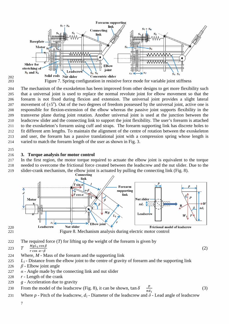
202 Figure 7. Spring configuration in resistive force mode for variable joint stiffness 203
The mechanism of the exoskeleton has been improved from other designs to get more flexibility such 204 that a universal joint is used to replace the normal revolute joint for elbow movement so that the 205 forearm is not fixed during flexion and extension. The universal joint provides a slight lateral 206 movement of (±5o). Out of the two degrees of freedom possessed by the universal joint, active one is 207 responsible for flexion-extension of the elbow whereas the passive joint supports flexibility in the 208 transverse plane during joint rotation. Another universal joint is used at the junction between the 209 leadscrew slider and the connecting link to support the joint flexibility. The user’s forearm is attached 210 to the exoskeleton’s forearm using cuff and straps. The forearm supporting link has discrete holes to 211 fit different arm lengths. To maintain the alignment of the centre of rotation between the exoskeleton 212 and user, the forearm has a passive translational joint with a compression spring whose length is 213 varied to match the forearm length of the user as shown in Fig. 3. 214
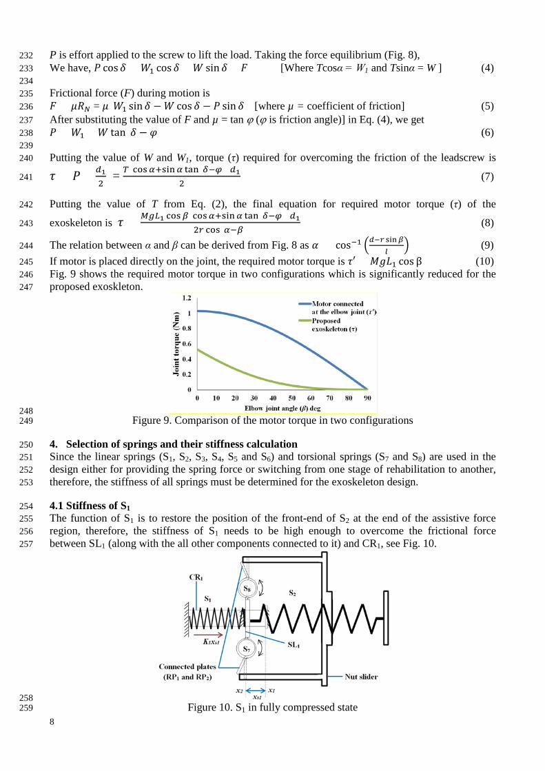
215 3. Torque analysis for motor control 216 In the first region, the motor torque required to actuate the elbow joint is equivalent to the torque 217 needed to overcome the frictional force created between the leadscrew and the nut slider. Due to the 218 slider-crank mechanism, the elbow joint is actuated by pulling the connecting link (Fig. 8). 219
220 Figure 8. Mechanism analysis during electric motor control 221
The required force (T) for lifting up the weight of the forearm is given by 222
𝑇 = 𝑀𝑀𝑛1 cos𝛽𝑟 cos(𝛼−𝛽) (2) 223
Where, M - Mass of the forearm and the supporting link 224 L1 - Distance from the elbow joint to the centre of gravity of forearm and the supporting link 225 β - Elbow joint angle 226 α - Angle made by the connecting link and nut slider 227 r - Length of the crank 228 g - Acceleration due to gravity 229 From the model of the leadscrew (Fig. 8), it can be shown, tan 𝛿 = 𝑝
𝜋𝑑1 (3) 230
Where p - Pitch of the leadscrew, d1 - Diameter of the leadscrew and δ - Lead angle of leadscrew 231
8
P is effort applied to the screw to lift the load. Taking the force equilibrium (Fig. 8), 232 We have, 𝑃 cos𝛿 = 𝑊1 cos𝛿 + 𝑊 sin 𝛿 + 𝐹 [Where Tcosα = W1 and Tsinα = W ] (4) 233 234 Frictional force (F) during motion is 235 𝐹 = 𝜇𝑅𝜋 = 𝜇(𝑊1 sin 𝛿 −𝑊 cos 𝛿 − 𝑃 sin 𝛿) [where µ = coefficient of friction] (5) 236 After substituting the value of F and µ = tan ϕ (ϕ is friction angle)] in Eq. (4), we get 237 𝑃 = 𝑊1 + 𝑊 tan(𝛿 − 𝜑) (6) 238 239 Putting the value of W and W1, torque (τ) required for overcoming the friction of the leadscrew is 240
𝜏 = 𝑃 × 𝑑12
= 𝑇(cos𝛼+sin𝛼 tan(𝛿−𝜑))𝑑12
(7) 241
Putting the value of T from Eq. (2), the final equation for required motor torque (τ) of the 242
exoskeleton is 𝜏 = 𝑀𝑀𝑛1 cos𝛽(cos𝛼+sin𝛼 tan(𝛿−𝜑))𝑑12𝑟 cos(𝛼−𝛽)
(8) 243
The relation between α and β can be derived from Fig. 8 as 𝛼 = cos−1 �𝑑−𝑟 sin𝛽𝑙
� (9) 244
If motor is placed directly on the joint, the required motor torque is 𝜏′ = 𝑀𝑀𝐿1 cos β (10) 245 Fig. 9 shows the required motor torque in two configurations which is significantly reduced for the 246 proposed exoskleton. 247
248 Figure 9. Comparison of the motor torque in two configurations 249
4. Selection of springs and their stiffness calculation 250 Since the linear springs (S1, S2, S3, S4, S5 and S6) and torsional springs (S7 and S8) are used in the 251 design either for providing the spring force or switching from one stage of rehabilitation to another, 252 therefore, the stiffness of all springs must be determined for the exoskeleton design. 253
4.1 Stiffness of S1 254 The function of S1 is to restore the position of the front-end of S2 at the end of the assistive force 255 region, therefore, the stiffness of S1 needs to be high enough to overcome the frictional force 256 between SL1 (along with the all other components connected to it) and CR1, see Fig. 10. 257
258 Figure 10. S1 in fully compressed state 259

9
Therefore, 𝐾1𝑥𝑠1 > 𝜇𝜇𝑀 (11) 260 Where K1 - Stiffness of S1 261 xs1 - Displacement covered by S1 in fully compressed position 262 µ - Coefficient of friction between SL1 and CR1 263 m - Weight of the assembly connected to SL1 264 g - Acceleration due to gravity 265 Based on the frictional property of SL1 and CR1 and mass of SL1, frictional force can be determined, 266 from where K1 can be estimated. S1 produces maximum force when it is fully compressed (x = x2) by 267 the nut slider. 268
4.2 Stiffness of S2 269 Spring force of S2 is mainly responsible for assisting the elbow movement in the second region (Fig. 270 11). In the exoskeleton, S2 will be extended for sharing the required torque used to rotate the joint 271 against gravity. 272
273 Figure 11. Force balancing in the assistive force mode (second region) 274
As linear bearings are used at the sliding contact between the concentric slider and leadscrew, the 275 frictional force during motion is considered negligible compared to the elbow actuation force and is 276 not taken into account. 277 The assistive force provided by S2 is 𝑓𝑠2 = 𝐾2(𝑥𝑠2 − 𝑥′𝑠2) (12) 278 Where K2 - Stiffness of S2, xs2 - Displacement of S2, x’s2 - Free length of S2. 279 Pulling force (T) along the connecting link is same as it is shown during the electric motor control. 280 Therefore, the value of T is taken from Eq. (2). The only difference is that S2 is taking the load 281 instead of the motor. 282 Therefore, by equilibrating forces in Fig. 11, the stiffness of S2 becomes 283
𝐾2 = 𝑀𝑀𝑛1 cosβ sinα𝑟 cos(𝛼−𝛽)(𝑥𝑠2−𝑥′𝑠2)
(13) 284
The displacement range of S2 can be increased by pushing the nut slider backward towards the 285 baseplate, thus providing more assistive force. 286
287 4.3 Stiffness of S3 and S4 288 The stiffness of S3 and S4 are used for changing the joint stiffness providing the resistive force (Fig. 289 12). The elbow joint stiffness is dependent on three springs (S2, S3 and S4). However, the spring 290 parameters of S2 are constant during the resistive force control, only the displacement of S3 and S4 is 291 changed to create a variable joint stiffness at the elbow joint. 292

10
293 Figure 12. Elbow exoskeleton during variable joint stiffness control 294
The component of the spring force exerted by S2 about the point C is given by, 295
𝑓′𝑠2 = 𝐾2�𝑥𝑠2−𝑥′𝑠2� cos(𝛼−𝛽)sinα (14) 296
Spring force exerted by S3, 297 𝑓𝑠3 = 𝐾3(𝑥 − 𝑟1𝛽 − 𝑥′𝑠3) [Where K3 - Stiffness of S3, x’s3 - Free length of S3] (15) 298 Spring force exerted by S4, 299 𝑓𝑠4 = 𝐾4(𝑥 + 𝑟1𝛽 − 𝑥′𝑠4) [Where K4 - Stiffness of S4, x’s4 - Free length of S4] (16) 300
Therefore the joint stiffness of the elbow joint is the torsional stiffness K’ which is given by 301
𝐾′ = 𝜏𝛽
= 𝑟1(𝑓𝑠4−𝑓𝑠3)𝛽
− 𝑟𝑓′𝑠2𝛽
(17) 302
Where r1 - Radius of the pulley connected at the elbow joint 303
Two pairs of S3 and S4 are connected in this mechanism; therefore, the force exerted by both springs 304 will be doubled. Substituting the value of fs2, fs3 and fs4 in Eq. (17), the elbow joint stiffness is given 305 by 306
𝐾′ =2𝑟1{(𝐾4−𝐾3)𝑥−(𝐾4𝑥′𝑠4−𝐾3𝑥′𝑠3)}− 𝐾2𝑟(𝑥𝑠2−𝑥′𝑠2)cos(𝛼−𝛽)
sinα
𝛽+ 2𝑟12(𝐾4 + 𝐾3) (18) 307
The joint stiffness variation is shown in Fig. 13. 308
309 Figure 13. Elbow joint stiffness variation for different position of the nut slider 310
4.4 Stiffness of S5 and S6 311 The stiffness of both compression springs (S5 and S6) used for locking operation is equally important 312 in switching operation between first and second region. The ratio of the stiffness of S5 and S6 313 depends on the construction parameters of the locking mechanism (Fig. 14). 314
11
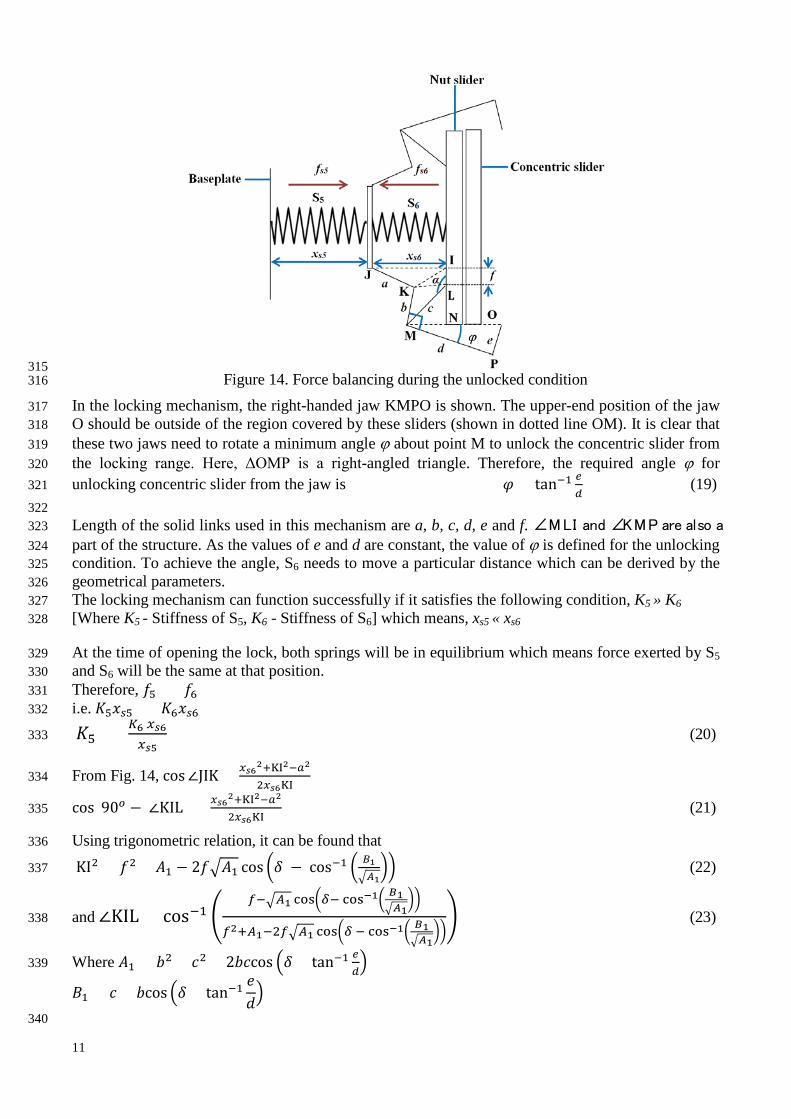
315 Figure 14. Force balancing during the unlocked condition 316
In the locking mechanism, the right-handed jaw KMPO is shown. The upper-end position of the jaw 317 O should be outside of the region covered by these sliders (shown in dotted line OM). It is clear that 318 these two jaws need to rotate a minimum angle ϕ about point M to unlock the concentric slider from 319 the locking range. Here, ΔOMP is a right-angled triangle. Therefore, the required angle ϕ for 320 unlocking concentric slider from the jaw is 𝜑 = tan−1 𝑒
𝑑 (19) 321
322 Length of the solid links used in this mechanism are a, b, c, d, e and f. ∠MLI and ∠KMP are also a 323 part of the structure. As the values of e and d are constant, the value of ϕ is defined for the unlocking 324 condition. To achieve the angle, S6 needs to move a particular distance which can be derived by the 325 geometrical parameters. 326 The locking mechanism can function successfully if it satisfies the following condition, K5 » K6 327 [Where K5 - Stiffness of S5, K6 - Stiffness of S6] which means, xs5 « xs6 328
At the time of opening the lock, both springs will be in equilibrium which means force exerted by S5 329 and S6 will be the same at that position. 330 Therefore, 𝑓5 = 𝑓6 331 i.e. 𝐾5𝑥𝑠5 = 𝐾6𝑥𝑠6 332
𝐾5 = 𝐾6 𝑥𝑠6𝑥𝑠5
(20) 333
From Fig. 14, cos∠JIK = 𝑥𝑠62+KI2−𝑎2
2𝑥𝑠6KI 334
cos(90𝑜 − ∠KIL) = 𝑥𝑠62+KI2−𝑎2
2𝑥𝑠6KI (21) 335
Using trigonometric relation, it can be found that 336
KI2 = 𝑓2 + 𝐴1 − 2𝑓�𝐴1 cos �𝛿 − cos−1 � 𝐵1�𝐴1
�� (22) 337
and ∠KIL = cos−1 �𝑓−�𝐴1 cos�𝛿− cos−1� 𝐵1
�𝐴1��
𝑓2+𝐴1−2𝑓�𝐴1 cos�𝛿 − cos−1� 𝐵1�𝐴1
��� (23) 338
Where 𝐴1 = 𝑏2 + 𝑐2 + 2𝑏𝑐cos �𝛿 + tan−1 𝑒𝑑� 339
𝐵1 = 𝑐 + 𝑏cos �𝛿 + tan−1𝑒𝑑�
340

12
After calculating the value of xs6, xs5 and putting in Eq. (20), we get relationship between K5 and K6. 341 342 The spring (S6) associated with the lock will experience a higher and opposite force from S5. After 343 opening of the lock, S6 cannot be compressed further due to the mechanical constraint thus 344 exhibiting a constant force for the rest of the motion. However, due to the movement of nut slider in 345 backward direction, S5 will be further compressed with a higher spring force which helps to maintain 346 the unlocked condition during rest of the range as shown Fig. 15. 347
348 Figure 15. Force generation in two springs of the locking mechanism 349
4.5 Stiffness of S7 and S8 350 Fig. 16 shows the force balancing of the mechanism during the final stage of the assistive mode 351 where both torsional springs S7 and S8 are at their maximum deflected position. The nut slider 352 generates an equal and opposite force against two torsional springs (S7 and S8) and balances the 353 forces generated by S1 and S2. Both S7 and S8 have equal stiffness as they are structurally the same. 354
355 Figure 16. Force balancing of the mechanism at the final stage of assistive force mode 356
From Fig. 16, it can be derived that, 357 𝜆 = cos−1(1 − 𝑎′
𝑟2) (24) 358
Where a’ - Width of the extension part of the nut slider, r2 - Length of the plates (RP1 and RP2) 359 Force produced by S1, 𝑓𝑠1 = 𝐾1𝑥𝑠1 [Where K1 - Stiffness of S1] (25) 360

13
Force produced by S2, 𝑓𝑠2 = 𝐾2(𝑥𝑠2 + 𝑥𝑠1 − 𝑥′𝑠2) (26) 361 For this mechanism, 𝐾7 = 𝐾8 [Where K7 - Stiffness of S7 and K8 - Stiffness of S8] 362
From Fig. 16, 𝜏′ = 𝐾7𝜆 363 Where λ - Angle made RP1 and RP2 at maximum deflected position 364 τ’ - Torque created by S7 and S8 365 𝐹′𝑟2 𝑐𝑐𝑠 𝜆 = 𝐾7𝜆 Where F’ - Reaction force by S7 and S8 366
Therefore, 𝐹′ = 𝐾7𝜆𝑟2 𝑐𝑜𝑠 𝜆
(27) 367
As S7 and S8 maintain the force in equilibrium, 368 2𝐹′ = 𝑓𝑠1 + 𝑓𝑠2 (28) 369
Putting the value of fs1 (from Eq. (25)), fs2 (from Eq. (26)) and F’ (from Eq. (27)) in Eq. (28), we 370
have 𝐾7 = 𝑟2 𝑐𝑜𝑠 𝜆�𝐾1𝑥𝑠1+𝐾2(𝑥𝑠2+𝑥𝑠1−𝑥′𝑠2)�2𝜆
(29) 371
After putting the value of λ (taken from Eq. (24)), the value of K7 will be, 372
K7 = (𝑟2−𝑎′)�𝐾1𝑥𝑠1+𝐾2(𝑥𝑠2+𝑥𝑠1−𝑥′𝑠2)�
2 𝑐𝑜𝑠−1(1−𝑎′𝑟2)
(30) 373
Based on the above design considerations, a functional prototype has been developed to establish the 374 working principle of the exoskeleton. All mechanical components have been manufactured using 3D 375 printer. The prototype of the elbow exoskeleton is shown in Fig. 17 along with its specifications. All 376 the sliding contacts have been developed with bearing to reduce the frictional loss during motion. 377 The prototype performs as per the requirements of the three stages of rehabilitation. 378 379
380 Figure 17. Prototype of the elbow exoskeleton with specifications 381
382 5. Conclusions 383 An innovative mechanism of the elbow exoskeleton has been developed which can accommodate 384 three modes of rehabilitation for different stages after stroke. In this design, we have attempted to 385 achieve the multistage post-stroke rehabilitation at mechanical level so that the device can be fine-386 tuned to user’s requirements. Full design details of the elbow exoskeleton have been presented 387 together with parametric relations for component selection. These design parameters can be tailored 388 to suit any user specific requirements. A prototype device has been developed to prove the principle. 389 For most exoskeletons, the motor torque is varied depending on the dynamics of the model and 390 patient’s requirement whereas in this exoskeleton the position of the nut-slider can produce different 391 exercise modes either under motor control or in assistive or resistive modes. The mechanism can 392 change the amount of assistive and resistive force by simply changing the position of the slider. Such 393 arrangement in a single structure offers flexibility to patients to select a particular type of exercise. 394

14
During the assistive and resistive modes only the spring force is used without engaging any active 395 actuator therefore the energy source is only used during the motor operation. The switching 396 mechanism safeguards users by restricting the reachable joint angle to the anatomical limit during 397 motor control mode. If the nut sliver goes up to the end of first rehabilitation region due to motor 398 rotation, the lock will be actived till the joint takes its maximum anatomical limit. Position of the nut 399 slider beyond the switching point will automatically open the lock, releasing the joint control from 400 motor and transfer it to the user, therefore providing safety and functionality at the same time. 401
References 402 [1] Feigin, V. L., Forouzanfar, M. H., Krishnamurthi, R., Mensah, G. A., Connor, M., Bennett, D. A., Moran, A. E., 403 Sacco, R. L., Anderson, L., and Truelsen, T., 2014, "Global and regional burden of stroke during 1990–2010: findings 404 from the Global Burden of Disease Study 2010," The Lancet, 383(9913), pp. 245-255. 405 [2] Saka, Ö., McGuire, A., and Wolfe, C., 2009, "Cost of stroke in the United Kingdom," Age and ageing, 38(1), pp. 27-406 32. 407 [3] Lo, A. C., Guarino, P. D., Richards, L. G., Haselkorn, J. K., Wittenberg, G. F., Federman, D. G., Ringer, R. J., 408 Wagner, T. H., Krebs, H. I., and Volpe, B. T., 2010, "Robot-assisted therapy for long-term upper-limb impairment after 409 stroke," New England Journal of Medicine, 362(19), pp. 1772-1783. 410 [4] Manna, S. K., and Dubey, V. N., 2016, "Upper arm exoskeleton –what specifications will meet users’ acceptability? 411 ," Robotics: New Research D. G. Fisher, ed., Nova Science Publisher, pp. 123-169. 412 [5] Proietti, T., Crocher, V., Roby-Brami, A., and Jarrassé, N., 2016, "Upper-limb robotic exoskeletons for 413 neurorehabilitation: a review on control strategies," IEEE Reviews in Biomedical Engineering, 9, pp. 4-14. 414 [6] Pineda-Rico, Z., de Lucio, J. A. S., Martinez Lopez, F. J., and Cruz, P., 2016, "2121. Design of an exoskeleton for 415 upper limb robot-assisted rehabilitation based on co-simulation," Journal of Vibroengineering, 18(5). 416 [7] Chonnaparamutt, W., and Supsi, W., 2016, "SEFRE: Semiexoskeleton Rehabilitation System," Applied Bionics and 417 Biomechanics, 2016. 418 [8] Beer, R. F., Naujokas, C., Bachrach, B., and Mayhew, D., "Development and evaluation of a gravity compensated 419 training environment for robotic rehabilitation of post-stroke reaching," 2008, Proc. 2nd IEEE RAS & EMBS 420 International Conference on Biomedical Robotics and Biomechatronics, IEEE, pp. 205-210. 421 [9] Kolar, P., 2014, Clinical rehabilitation, Alena Kobesová. 422 [10] Jarrassé, N., Proietti, T., Crocher, V., Robertson, J., Sahbani, A., Morel, G., and Roby-Brami, A., 2014, "Robotic 423 exoskeletons: a perspective for the rehabilitation of arm coordination in stroke patients," Frontiers in Human 424 Neuroscience, 8, p. 947. 425 [11] Wolbrecht, E. T., Chan, V., Reinkensmeyer, D. J., and Bobrow, J. E., 2008, "Optimizing compliant, model-based 426 robotic assistance to promote neurorehabilitation," IEEE Transactions on Neural Systems and Rehabilitation 427 Engineering, 16(3), pp. 286-297. 428 [12] Maciejasz, P., Eschweiler, J., Gerlach-Hahn, K., Jansen-Troy, A., and Leonhardt, S., 2014, "A survey on robotic 429 devices for upper limb rehabilitation," Journal of Neuroengineering and Rehabilitation, 11(1), p. 3. 430 [13] Bhadane, M., Liu, J., Rymer, W. Z., Zhou, P., and Li, S., 2016, "Re-evaluation of EMG-torque relation in chronic 431 stroke using linear electrode array EMG recordings," Scientific Reports, 6, p. 28957. 432 [14] Marchal-Crespo, L., and Reinkensmeyer, D. J., 2009, "Review of control strategies for robotic movement training 433 after neurologic injury," Journal of Neuroengineering and Rehabilitation, 6(1), p. 20. 434 [15] Marcheschi, S., Salsedo, F., Fontana, M., and Bergamasco, M., "Body extender: whole body exoskeleton for human 435 power augmentation," Proc. 2011 IEEE International Conference on Robotics and Automation (ICRA), IEEE, pp. 611-436 616. 437 [16] Manna, S. K., and Dubey, V. N., 2018, "Comparative study of actuation systems for portable upper limb 438 exoskeletons," Medical Engineering & Physics, 60, pp. 1-13. 439 [17] Housman, S. J., Le, V., Rahman, T., Sanchez, R. J., and Reinkensmeyer, D. J., "Arm-training with T-WREX after 440 chronic stroke: preliminary results of a randomized controlled trial," Proc. IEEE 10th International Conference on 441 Rehabilitation Robotics, 2007, IEEE, pp. 562-568. 442 [18] Sanchez, R., Reinkensmeyer, D., Shah, P., Liu, J., Rao, S., Smith, R., Cramer, S., Rahman, T., and Bobrow, J., 443 "Monitoring functional arm movement for home-based therapy after stroke," Proc. 26th Annual International Conference 444 of the IEEE Engineering in Medicine and Biology Society, 2004, IEEE, pp. 4787-4790. 445 [19] Crea, S., Cempini, M., Moisè, M., Baldoni, A., Trigili, E., Marconi, D., Cortese, M., Giovacchini, F., Posteraro, F., 446 and Vitiello, N., "A novel shoulder-elbow exoskeleton with series elastic actuators," Proc. 2016 6th IEEE International 447 Conference on Biomedical Robotics and Biomechatronics (BioRob), IEEE, pp. 1248-1253. 448 [20] Van Ham, R., Sugar, T. G., Vanderborght, B., Hollander, K. W., and Lefeber, D., 2009, "Compliant actuator 449 designs," IEEE Robotics & Automation Magazine, 16(3). 450 451 452