z/os mvs authorized assembler services reference … facility services ..... . 57 description ........
TRANSCRIPT

z/OS
MVS Programming: Authorized AssemblerServices Reference, Volume 4 (SET-WTO)Version 2 Release 3
SA23-1375-30
IBM

NoteBefore using this information and the product it supports, read the information in “Notices” on page 425.
This edition applies to Version 2 Release 3 of z/OS (5650-ZOS) and to all subsequent releases and modificationsuntil otherwise indicated in new editions.
Last updated: April 18, 2018
© Copyright IBM Corporation 1988, 2017.US Government Users Restricted Rights – Use, duplication or disclosure restricted by GSA ADP Schedule Contractwith IBM Corp.
Contents
Figures . . . . . . . . . . . . . . . xi
Tables . . . . . . . . . . . . . . . xiii
About this information . . . . . . . . xvWho should use this information . . . . . . . xvHow to use this information. . . . . . . . . xvz/OS information . . . . . . . . . . . . xv
How to send your comments to IBM xviiIf you have a technical problem . . . . . . . xvii
Summary of changes . . . . . . . . xixSummary of changes for z/OS Version 2 Release 3 xixSummary of changes for z/OS Version 2 Release 2 xixz/OS Version 2 Release 1 summary of changes . . xx
Chapter 1. Using the services . . . . . 1Compatibility of MVS macros. . . . . . . . . 1Addressing mode (AMODE) . . . . . . . . . 2Address space control (ASC) mode . . . . . . . 3
ALET qualification . . . . . . . . . . . 4User parameters . . . . . . . . . . . . 4
Telling the system about the execution environment 6Specifying a macro version number. . . . . . . 7
How to request a macro version using PLISTVER 7Register use . . . . . . . . . . . . . . 8Handling return codes and reason codes . . . . . 9
Handling program errors . . . . . . . . . 10Handling environmental and system errors . . . 10
Using X-macros . . . . . . . . . . . . . 11Macro forms . . . . . . . . . . . . . . 12
Conventional list form macros . . . . . . . 12Alternative list form macros . . . . . . . . 13
Coding the macros . . . . . . . . . . . . 13Continuation lines . . . . . . . . . . . 16
Coding the callable services . . . . . . . . . 16Including equate (EQU) statements . . . . . 17Link-editing linkage-assist routines . . . . . 17
Service summary . . . . . . . . . . . . 18
Chapter 2. SETFRR — Set upfunctional recovery routines . . . . . 29Description . . . . . . . . . . . . . . 29
Environment . . . . . . . . . . . . . 29Programming requirements . . . . . . . . 29Restrictions . . . . . . . . . . . . . 30Input register information . . . . . . . . 30Output register information . . . . . . . . 30Performance implications . . . . . . . . . 30Syntax . . . . . . . . . . . . . . . 30Parameters . . . . . . . . . . . . . 31ABEND codes . . . . . . . . . . . . 33Return and reason codes . . . . . . . . . 33
Example 1 . . . . . . . . . . . . . . 33Example 2 . . . . . . . . . . . . . . 34
Chapter 3. SETLOCK — Control accessto serially reusable resources . . . . . 35Description . . . . . . . . . . . . . . 35
Environment . . . . . . . . . . . . . 35Programming requirements . . . . . . . . 35Restrictions . . . . . . . . . . . . . 35Input register information . . . . . . . . 36Output register information . . . . . . . . 36Performance implications . . . . . . . . . 37
SETLOCK OBTAIN. . . . . . . . . . . . 37Syntax . . . . . . . . . . . . . . . 37Parameters . . . . . . . . . . . . . 37ABEND codes . . . . . . . . . . . . 39Return and reason codes . . . . . . . . . 40Example 1 . . . . . . . . . . . . . . 40Example 2 . . . . . . . . . . . . . . 40Example 3 . . . . . . . . . . . . . . 40
SETLOCK RELEASE . . . . . . . . . . . 41Syntax . . . . . . . . . . . . . . . 41Parameters . . . . . . . . . . . . . 41Return and reason codes . . . . . . . . . 43Example 1 . . . . . . . . . . . . . . 43Example 2 . . . . . . . . . . . . . . 44
SETLOCK TEST . . . . . . . . . . . . . 44Syntax . . . . . . . . . . . . . . . 44Parameters . . . . . . . . . . . . . 45Return and reason codes . . . . . . . . . 46Example 1 . . . . . . . . . . . . . . 46Example 2 . . . . . . . . . . . . . . 46Example 3 . . . . . . . . . . . . . . 46
Chapter 4. SETRP — Set returnparameters . . . . . . . . . . . . . 47Description . . . . . . . . . . . . . . 47
Environment . . . . . . . . . . . . . 47Programming requirements . . . . . . . . 47Restrictions . . . . . . . . . . . . . 47Input register information . . . . . . . . 48Output register information . . . . . . . . 48Performance implications . . . . . . . . . 49Syntax . . . . . . . . . . . . . . . 49Parameters . . . . . . . . . . . . . 51ABEND codes . . . . . . . . . . . . 56Return and reason codes . . . . . . . . . 56Example 1 . . . . . . . . . . . . . . 56Example 2 . . . . . . . . . . . . . . 56
Chapter 5. SJFREQ — Call schedulerJCL facility services . . . . . . . . . 57Description . . . . . . . . . . . . . . 57
Environment . . . . . . . . . . . . . 57
© Copyright IBM Corp. 1988, 2017 iii
||

Programming requirements . . . . . . . . 58Restrictions . . . . . . . . . . . . . 58Input register information . . . . . . . . 58Output register information . . . . . . . . 58Performance implications . . . . . . . . . 59Syntax . . . . . . . . . . . . . . . 59Parameters . . . . . . . . . . . . . 59Example . . . . . . . . . . . . . . 60
SJFREQ RETRIEVE service . . . . . . . . . 63Programming requirements . . . . . . . . 63SJFREQ RETRIEVE keyword list . . . . . . 63SJFREQ RETRIEVE input parameters . . . . . 64SJFREQ RETRIEVE output parameters . . . . 65ABEND codes . . . . . . . . . . . . 65SJFREQ RETRIEVE return and reason codes . . 65
SJFREQ SWBTU_MERGE service . . . . . . . 67Programming requirements . . . . . . . . 67SJFREQ SWBTU_MERGE input parameters. . . 67SJFREQ SWBTU_MERGE output parameters . . 69SJFREQ SWBTU_MERGE ABEND codes. . . . 69SJFREQ SWBTU_MERGE Return and reasoncodes . . . . . . . . . . . . . . . 69
SJFREQ VERIFY service . . . . . . . . . . 76SJFREQ VERIFY input parameters . . . . . . 76SJFREQ VERIFY output parameters . . . . . 80Operand descriptions . . . . . . . . . . 81ABEND codes . . . . . . . . . . . . 82Return and reason codes with related messagetext . . . . . . . . . . . . . . . . 82
SJFREQ TERMINATE service . . . . . . . . 90SJFREQ TERMINATE input parameters . . . . 90Return and reason codes . . . . . . . . . 90
Chapter 6. SPIE — Specify programinterruption exit . . . . . . . . . . . 91Description . . . . . . . . . . . . . . 91
Environment . . . . . . . . . . . . . 91Programming requirements . . . . . . . . 92Restrictions . . . . . . . . . . . . . 92Input register information . . . . . . . . 92Output register information . . . . . . . . 92Performance implications . . . . . . . . . 93Syntax . . . . . . . . . . . . . . . 93Parameters . . . . . . . . . . . . . 93ABEND codes . . . . . . . . . . . . 94Return and reason codes . . . . . . . . . 94Example . . . . . . . . . . . . . . 94
SPIE - List form . . . . . . . . . . . . . 94Syntax . . . . . . . . . . . . . . . 94Parameters . . . . . . . . . . . . . 95
SPIE - Execute form . . . . . . . . . . . 95Syntax . . . . . . . . . . . . . . . 95Parameters . . . . . . . . . . . . . 96
Chapter 7. SPOST — SynchronizePOST . . . . . . . . . . . . . . . 97Description . . . . . . . . . . . . . . 97
Environment . . . . . . . . . . . . . 97Programming requirements . . . . . . . . 97Restrictions . . . . . . . . . . . . . 97
Input register information . . . . . . . . 97Output register information . . . . . . . . 97Performance implications . . . . . . . . . 98Syntax . . . . . . . . . . . . . . . 98ABEND codes . . . . . . . . . . . . 98Return and reason codes . . . . . . . . . 98Example . . . . . . . . . . . . . . 98
Chapter 8. SRBSTAT — Save, restore,or modify SRB status . . . . . . . . 99Description . . . . . . . . . . . . . . 99
Environment . . . . . . . . . . . . . 99Programming requirements . . . . . . . . 99Restrictions . . . . . . . . . . . . . 99Input register information . . . . . . . . 99Output register information . . . . . . . . 99Performance implications . . . . . . . . 100Syntax. . . . . . . . . . . . . . . 100Parameters . . . . . . . . . . . . . 101ABEND codes . . . . . . . . . . . . 102Return and reason codes . . . . . . . . 102
Chapter 9. SRBTIMER — Establishtime limit for system service . . . . . 103Description . . . . . . . . . . . . . . 103
Environment . . . . . . . . . . . . 103Programming requirements. . . . . . . . 103Restrictions . . . . . . . . . . . . . 103Input register information . . . . . . . . 103Output register information . . . . . . . 103Performance implications . . . . . . . . 104Syntax. . . . . . . . . . . . . . . 104Parameters . . . . . . . . . . . . . 104ABEND codes . . . . . . . . . . . . 104Return codes . . . . . . . . . . . . 105
Chapter 10. STATUS — Controldispatchability or process-must-complete state . . . . . . . . . . . 107Description . . . . . . . . . . . . . . 107
Environment . . . . . . . . . . . . 107Programming requirements. . . . . . . . 108Restrictions . . . . . . . . . . . . . 108Register information . . . . . . . . . . 108Performance implications . . . . . . . . 109
START/STOP options . . . . . . . . . . 109Syntax. . . . . . . . . . . . . . . 109Parameters . . . . . . . . . . . . . 110Return codes . . . . . . . . . . . . 110
SET/RESET option . . . . . . . . . . . 111Syntax . . . . . . . . . . . . . . . 111Parameters . . . . . . . . . . . . . 111Return codes . . . . . . . . . . . . 111Example . . . . . . . . . . . . . . 112
Chapter 11. STORAGE — Obtain andrelease storage . . . . . . . . . . 115Description . . . . . . . . . . . . . . 115
Environment . . . . . . . . . . . . 115
iv z/OS MVS Authorized Assembler Services Reference SET-WTO

Programming requirements . . . . . . . . 117Restrictions . . . . . . . . . . . . . 117Register information . . . . . . . . . . 117Performance implications . . . . . . . . 117
STORAGE OBTAIN . . . . . . . . . . . 117Input register information forLINKAGE=SYSTEM . . . . . . . . . . 117Output register information forLINKAGE=SYSTEM . . . . . . . . . . 117Input register information for LINKAGE=SVC 118Output register information for LINKAGE=SVC 118Input register information forLINKAGE=BRANCH. . . . . . . . . . 119Output register information forLINKAGE=BRANCH. . . . . . . . . . 119Input register information forLINKAGE=GLOBALBRANCH . . . . . . 120Output register information forLINKAGE=GLOBALBRANCH . . . . . . 120Syntax. . . . . . . . . . . . . . . 120Parameters . . . . . . . . . . . . . 123ABEND codes . . . . . . . . . . . . 131Return and reason codes . . . . . . . . 131Examples . . . . . . . . . . . . . . 133
STORAGE RELEASE . . . . . . . . . . . 133Input register information forLINKAGE=SYSTEM . . . . . . . . . . 133Output register information forLINKAGE=SYSTEM . . . . . . . . . . 133Input register information for LINKAGE=SVC 133Output register information for LINKAGE=SVC 134Input register information forLINKAGE=BRANCH. . . . . . . . . . 134Output register information forLINKAGE=BRANCH. . . . . . . . . . 134Input register information forLINKAGE=GLOBALBRANCH . . . . . . 135Output register information forLINKAGE=GLOBALBRANCH . . . . . . 135Syntax. . . . . . . . . . . . . . . 136Parameters . . . . . . . . . . . . . 137ABEND codes . . . . . . . . . . . . 139Return and reason codes . . . . . . . . 139Examples of the OBTAIN and RELEASE options 140
Chapter 12. SUSPEND — Suspendexecution of an RB . . . . . . . . . 143Description . . . . . . . . . . . . . . 143
Environment . . . . . . . . . . . . 143Programming requirements. . . . . . . . 143Restrictions . . . . . . . . . . . . . 143Input register information . . . . . . . . 143Output register information . . . . . . . 143Performance implications . . . . . . . . 144Syntax. . . . . . . . . . . . . . . 144Parameters . . . . . . . . . . . . . 144ABEND codes . . . . . . . . . . . . 144Return and reason codes . . . . . . . . 144Example . . . . . . . . . . . . . . 144
Chapter 13. SUSPEND — Suspendexecution of an SRB . . . . . . . . 145Description . . . . . . . . . . . . . . 145
Environment . . . . . . . . . . . . 145Programming requirements. . . . . . . . 145Restrictions . . . . . . . . . . . . . 145Input register information . . . . . . . . 146Output register information . . . . . . . 146Performance implications . . . . . . . . 146Syntax. . . . . . . . . . . . . . . 146Parameters . . . . . . . . . . . . . 147ABEND codes . . . . . . . . . . . . 147Return codes . . . . . . . . . . . . 147Example . . . . . . . . . . . . . . 148
SUSPEND (SRB) - List form . . . . . . . . 148Syntax. . . . . . . . . . . . . . . 148Parameters . . . . . . . . . . . . . 149
SUSPEND (SRB) - Execute form . . . . . . . 149Syntax. . . . . . . . . . . . . . . 149Parameters . . . . . . . . . . . . . 150
Chapter 14. SVCUPDTE — SVCupdate . . . . . . . . . . . . . . 151Description . . . . . . . . . . . . . . 151
Environment . . . . . . . . . . . . 151Programming requirements. . . . . . . . 151Restrictions . . . . . . . . . . . . . 151Input register information . . . . . . . . 151Output register information . . . . . . . 151Performance implications . . . . . . . . 152Syntax. . . . . . . . . . . . . . . 152Parameters . . . . . . . . . . . . . 153ABEND codes . . . . . . . . . . . . 155Return codes . . . . . . . . . . . . 155Example 1 . . . . . . . . . . . . . 157Example 2 . . . . . . . . . . . . . 157Example 3 . . . . . . . . . . . . . 157Example 4 . . . . . . . . . . . . . 157Example 5 . . . . . . . . . . . . . 157Example 6 . . . . . . . . . . . . . 157
SVCUPDTE - List form . . . . . . . . . . 158Syntax. . . . . . . . . . . . . . . 158Parameters . . . . . . . . . . . . . 159Example 1 . . . . . . . . . . . . . 159Example 2 . . . . . . . . . . . . . 159
SVCUPDTE - Execute form . . . . . . . . . 159Syntax. . . . . . . . . . . . . . . 159Parameters . . . . . . . . . . . . . 160Example . . . . . . . . . . . . . . 160
Chapter 15. SWAREQ — Invoke SWAmanager in locate mode. . . . . . . 161Description . . . . . . . . . . . . . . 161
Environment . . . . . . . . . . . . 161Programming requirements. . . . . . . . 162Restrictions . . . . . . . . . . . . . 162Input register information . . . . . . . . 162Output register information . . . . . . . 162Performance implications . . . . . . . . 163ABEND codes . . . . . . . . . . . . 163
Contents v

Return and reason codes . . . . . . . . 163SWAREQ - List form . . . . . . . . . . . 163
Syntax. . . . . . . . . . . . . . . 163Parameters . . . . . . . . . . . . . 164
SWAREQ - Execute form . . . . . . . . . 164Syntax. . . . . . . . . . . . . . . 164Parameters . . . . . . . . . . . . . 165
SWAREQ - Modify form. . . . . . . . . . 165Syntax. . . . . . . . . . . . . . . 165Parameters . . . . . . . . . . . . . 166
Chapter 16. SWBTUREQ — Call SJFSWBTU processing services . . . . . 167Description . . . . . . . . . . . . . . 167
Environment . . . . . . . . . . . . 167Programming requirements. . . . . . . . 167Restrictions . . . . . . . . . . . . . 168Input register information . . . . . . . . 168Output register information . . . . . . . 168Performance implications . . . . . . . . 168Syntax. . . . . . . . . . . . . . . 168Parameters . . . . . . . . . . . . . 168SWBTUREQ RETRIEVE service . . . . . . 169SWBTUREQ RETRIEVE input parameters . . . 169SWBTUREQ RETRIEVE output . . . . . . 170ABEND codes . . . . . . . . . . . . 171Return and reason codes . . . . . . . . 171Example . . . . . . . . . . . . . . 174
Chapter 17. SYNCH and SYNCHX —Take a synchronous exit to aprocessing program . . . . . . . . 177Description . . . . . . . . . . . . . . 177
Environment . . . . . . . . . . . . 177Programming requirements. . . . . . . . 178Restrictions . . . . . . . . . . . . . 178Register information . . . . . . . . . . 178Syntax. . . . . . . . . . . . . . . 178Parameters . . . . . . . . . . . . . 179Example 1 . . . . . . . . . . . . . 181Example 2 . . . . . . . . . . . . . 181Example 3 . . . . . . . . . . . . . 181Example 4 . . . . . . . . . . . . . 181
SYNCHX - Take a synchronous exit to a processingprogram . . . . . . . . . . . . . . . 181
Syntax. . . . . . . . . . . . . . . 182Parameters . . . . . . . . . . . . . 183
SYNCH and SYNCHX - List form . . . . . . 183Syntax. . . . . . . . . . . . . . . 183Parameters . . . . . . . . . . . . . 183Example . . . . . . . . . . . . . . 184
SYNCH and SYNCHX - Execute form . . . . . 184Syntax. . . . . . . . . . . . . . . 184Parameters . . . . . . . . . . . . . 185Example . . . . . . . . . . . . . . 185
Chapter 18. SYSEVENT — Systemevent . . . . . . . . . . . . . . . 187Description . . . . . . . . . . . . . . 187
Environment . . . . . . . . . . . . 187Programming requirements. . . . . . . . 188Restrictions and limitations . . . . . . . . 188Input register information . . . . . . . . 188Output register information . . . . . . . 188Syntax. . . . . . . . . . . . . . . 189Parameters . . . . . . . . . . . . . 190
SYSEVENT mnemonics . . . . . . . . . . 191Notify SRM of transaction completion (TRAXRPT,TRAXFRPT, TRAXERPT) . . . . . . . . . 191
Return and reason codes . . . . . . . . 193Example 1 . . . . . . . . . . . . . 193Example 2 . . . . . . . . . . . . . 194Example 3 . . . . . . . . . . . . . 194
Control swapping (DONTSWAP, OKSWAP,TRANSWAP) . . . . . . . . . . . . . 195
Example 1 . . . . . . . . . . . . . 196Example 2 . . . . . . . . . . . . . 196
Obtain system measurement information(STGTEST) . . . . . . . . . . . . . . 196
Example . . . . . . . . . . . . . . 197Obtain address space classification information(REQASCL) . . . . . . . . . . . . . . 198
Input register information . . . . . . . . 198Return and reason codes . . . . . . . . 198Input register information . . . . . . . . 198
Obtain address space related information(REQASD and REQFASD) . . . . . . . . . 198
Input register information . . . . . . . . 199Return and reason codes . . . . . . . . 199Example 1 . . . . . . . . . . . . . 200Example 2 . . . . . . . . . . . . . 200
Obtain workload management mode statusinformation (REQSRMST) . . . . . . . . . 200
Input register information . . . . . . . . 200Return and reason codes . . . . . . . . 201
Obtain data for defined capacity (REQLPDAT) . . 201Input register information . . . . . . . . 201Return and reason codes . . . . . . . . 202
Identify holder of a resource (ENQHOLD). . . . 202Input register information . . . . . . . . 203Return and reason codes . . . . . . . . 203
Identify that a holder has released resource(ENQRLSE) . . . . . . . . . . . . . . 204
Input register information . . . . . . . . 204Return and reason codes . . . . . . . . 204
Associate an enclave with an address space(ENCASSOC) . . . . . . . . . . . . . 204
Input register information . . . . . . . . 205Return and reason codes . . . . . . . . 205
Set the state for an enclave (ENCSTATE) . . . . 206Input register information . . . . . . . . 206
Query amount of free AUX storage (FREEAUX) 206Output register information . . . . . . . 206
Return resource contention information(QRYCONT). . . . . . . . . . . . . . 206
Input register information . . . . . . . . 206Return codes . . . . . . . . . . . . 206
Query a virtual server (QVS) . . . . . . . . 207Return and reason codes . . . . . . . . 209
vi z/OS MVS Authorized Assembler Services Reference SET-WTO

Chapter 19. TCBTOKEN — Request ortranslate the TTOKEN . . . . . . . . 211Description . . . . . . . . . . . . . . 211
Environment . . . . . . . . . . . . 211Programming requirements. . . . . . . . 212Restrictions . . . . . . . . . . . . . 212Register information . . . . . . . . . . 212Performance implications . . . . . . . . 212Syntax. . . . . . . . . . . . . . . 212Parameters . . . . . . . . . . . . . 213Abend codes . . . . . . . . . . . . 215Return codes . . . . . . . . . . . . 215Example 1 . . . . . . . . . . . . . 216Example 2 . . . . . . . . . . . . . 216Example 3 . . . . . . . . . . . . . 216
TCBTOKEN - List form . . . . . . . . . . 216Syntax. . . . . . . . . . . . . . . 217Parameters . . . . . . . . . . . . . 217
TCBTOKEN - Execute form . . . . . . . . 217Syntax. . . . . . . . . . . . . . . 217Parameters . . . . . . . . . . . . . 218
Chapter 20. TCTL — Transfer controlfrom an SRB routine . . . . . . . . 219Description . . . . . . . . . . . . . . 219
Environment . . . . . . . . . . . . 219Programming requirements. . . . . . . . 219Restrictions . . . . . . . . . . . . . 219Input register information . . . . . . . . 219Output register information . . . . . . . 219Performance implications . . . . . . . . 219Syntax. . . . . . . . . . . . . . . 219Parameters . . . . . . . . . . . . . 220ABEND codes . . . . . . . . . . . . 220Return and reason codes . . . . . . . . 220Example . . . . . . . . . . . . . . 220
Chapter 21. TESTAUTH — Testauthorization of caller. . . . . . . . 221Description . . . . . . . . . . . . . . 221
Environment . . . . . . . . . . . . 221Programming requirements. . . . . . . . 221Restrictions . . . . . . . . . . . . . 221Input register information . . . . . . . . 222Output register information . . . . . . . 222Performance implications . . . . . . . . 222Syntax. . . . . . . . . . . . . . . 222Parameters . . . . . . . . . . . . . 223ABEND codes . . . . . . . . . . . . 224Return codes . . . . . . . . . . . . 224Example 1 . . . . . . . . . . . . . 224Example 2 . . . . . . . . . . . . . 224
Chapter 22. TIMEUSED — Obtainaccumulated CPU or vector time . . . 225Description . . . . . . . . . . . . . . 225
Environment . . . . . . . . . . . . 225Programming requirements. . . . . . . . 225Restrictions . . . . . . . . . . . . . 226
Input register information . . . . . . . . 226Output register information . . . . . . . 226Performance implications . . . . . . . . 227Syntax. . . . . . . . . . . . . . . 228Parameters . . . . . . . . . . . . . 228Return codes . . . . . . . . . . . . 230Example 1 . . . . . . . . . . . . . 231Example 2 . . . . . . . . . . . . . 231Example 3 . . . . . . . . . . . . . 231
Chapter 23. T6EXIT — Type 6 exit. . . 233Description . . . . . . . . . . . . . . 233
Environment . . . . . . . . . . . . 233Programming requirements. . . . . . . . 233Restrictions . . . . . . . . . . . . . 233Input register information . . . . . . . . 233Output register information . . . . . . . 233Performance implications . . . . . . . . 233Syntax. . . . . . . . . . . . . . . 233Parameter . . . . . . . . . . . . . 234ABEND codes . . . . . . . . . . . . 234Return and reason codes . . . . . . . . 234Example . . . . . . . . . . . . . . 234
Chapter 24. UCBINFO — Returninformation from a UCB . . . . . . . 235Description . . . . . . . . . . . . . . 235
Environment . . . . . . . . . . . . 236Programming requirements. . . . . . . . 236Restrictions . . . . . . . . . . . . . 237Input register information . . . . . . . . 237Output register information . . . . . . . 237Performance implications . . . . . . . . 237
UCBINFO DEVCOUNT . . . . . . . . . . 237Syntax. . . . . . . . . . . . . . . 237Parameters . . . . . . . . . . . . . 239Return and reason codes . . . . . . . . 241Example . . . . . . . . . . . . . . 241
UCBINFO DEVCOUNT—List form . . . . . . 242Parameters . . . . . . . . . . . . . 242
UCBINFO DEVCOUNT—Execute form. . . . . 243Parameters . . . . . . . . . . . . . 244
UCBINFO DEVINFO . . . . . . . . . . . 244Syntax. . . . . . . . . . . . . . . 244Parameters . . . . . . . . . . . . . 245Return and reason codes . . . . . . . . 247Example . . . . . . . . . . . . . . 248
UCBINFO DEVINFO - List form . . . . . . . 248Parameters . . . . . . . . . . . . . 249
UCBINFO DEVINFO - Execute form . . . . . 249Parameters . . . . . . . . . . . . . 251
UCBINFO GETCDR . . . . . . . . . . . 251Syntax. . . . . . . . . . . . . . . 251Parameters . . . . . . . . . . . . . 252Return and reason codes . . . . . . . . 254Example . . . . . . . . . . . . . . 255
UCBINFO GETCDR - List form . . . . . . . 255Parameters . . . . . . . . . . . . . 256
UCBINFO GETCDR - Execute form . . . . . . 256Parameters . . . . . . . . . . . . . 258
Contents vii
||||||||||||||||||

UCBINFO HYPERPAVALIASES . . . . . . . 258Syntax. . . . . . . . . . . . . . . 258Parameters . . . . . . . . . . . . . 259Return and reason codes . . . . . . . . 261Example . . . . . . . . . . . . . . 262
UCBINFO HYPERPAVALIASES - List form . . . 263Parameters . . . . . . . . . . . . . 263
UCBINFO HYPERPAVALIASES - Execute form . . 264Parameters . . . . . . . . . . . . . 265
UCBINFO PATHINFO . . . . . . . . . . 265Syntax. . . . . . . . . . . . . . . 265Parameters . . . . . . . . . . . . . 266Return and reason codes . . . . . . . . 268Example . . . . . . . . . . . . . . 269
UCBINFO PATHINFO - List form . . . . . . 269Parameters . . . . . . . . . . . . . 270
UCBINFO PATHINFO - Execute form . . . . . 270Parameters . . . . . . . . . . . . . 271
UCBINFO PATHMAP . . . . . . . . . . 272Syntax. . . . . . . . . . . . . . . 272Parameters . . . . . . . . . . . . . 273Return and reason codes . . . . . . . . 274Example . . . . . . . . . . . . . . 275
UCBINFO PATHMAP - List form. . . . . . . 276Parameters . . . . . . . . . . . . . 276
UCBINFO PATHMAP - Execute form . . . . . 277Parameters . . . . . . . . . . . . . 278
UCBINFO PAVINFO . . . . . . . . . . . 278Syntax. . . . . . . . . . . . . . . 278Parameters . . . . . . . . . . . . . 279Return and reason codes . . . . . . . . 282Example . . . . . . . . . . . . . . 284
UCBINFO PAVINFO - List form . . . . . . . 284Parameters . . . . . . . . . . . . . 285
UCBINFO PAVINFO - Execute form. . . . . . 285Parameters . . . . . . . . . . . . . 287
UCBINFO PRFXDATA . . . . . . . . . . 287Syntax. . . . . . . . . . . . . . . 287Parameters . . . . . . . . . . . . . 288Return and reason codes . . . . . . . . 290Example . . . . . . . . . . . . . . 291
UCBINFO PRFXDATA - List form . . . . . . 291Parameters . . . . . . . . . . . . . 291
UCBINFO PRFXDATA - Execute form . . . . . 292Parameters . . . . . . . . . . . . . 293
Chapter 25. UCBLOOK — Obtainaddresses of UCB segments . . . . . 295Description . . . . . . . . . . . . . . 295
Environment . . . . . . . . . . . . 295Programming requirements. . . . . . . . 296Restrictions . . . . . . . . . . . . . 296Input register information . . . . . . . . 296Output register information . . . . . . . 296Performance implications . . . . . . . . 296Syntax. . . . . . . . . . . . . . . 296Parameters . . . . . . . . . . . . . 298ABEND codes . . . . . . . . . . . . 301Return and reason codes . . . . . . . . 301
UCBLOOK - List form . . . . . . . . . . 303Syntax. . . . . . . . . . . . . . . 303
Parameters . . . . . . . . . . . . . 303UCBLOOK - Execute form . . . . . . . . . 304
Syntax. . . . . . . . . . . . . . . 304Parameters . . . . . . . . . . . . . 306
Chapter 26. UCBPIN — Pinning orunpinning a UCB . . . . . . . . . . 307Description . . . . . . . . . . . . . . 307
Environment . . . . . . . . . . . . 307Programming requirements. . . . . . . . 307Restrictions . . . . . . . . . . . . . 307Register information . . . . . . . . . . 308Performance implications . . . . . . . . 308Syntax. . . . . . . . . . . . . . . 308Parameters . . . . . . . . . . . . . 310Return and reason codes . . . . . . . . 311
UCBPIN - List form . . . . . . . . . . . 312Syntax. . . . . . . . . . . . . . . 312Parameters . . . . . . . . . . . . . 312
UCBPIN - Execute form . . . . . . . . . . 312Syntax. . . . . . . . . . . . . . . 313Parameters . . . . . . . . . . . . . 314
Chapter 27. UCBSCAN — Scan UCBs 315Description . . . . . . . . . . . . . . 315
Environment . . . . . . . . . . . . 316Programming requirements. . . . . . . . 316Restrictions . . . . . . . . . . . . . 316Input register information . . . . . . . . 316Output register information . . . . . . . 316Performance implications . . . . . . . . 317Parameters . . . . . . . . . . . . . 317Return and reason codes . . . . . . . . 321
UCBSCAN COPY . . . . . . . . . . . . 322Syntax. . . . . . . . . . . . . . . 322
UCBSCAN COPY - List form . . . . . . . . 324Syntax. . . . . . . . . . . . . . . 325Parameters . . . . . . . . . . . . . 325
UCBSCAN COPY - Execute form. . . . . . . 325Syntax. . . . . . . . . . . . . . . 326Parameters . . . . . . . . . . . . . 328
UCBSCAN ADDRESS . . . . . . . . . . 328Syntax. . . . . . . . . . . . . . . 328Parameters . . . . . . . . . . . . . 330Return and reason codes . . . . . . . . 334
UCBSCAN ADDRESS - List form. . . . . . . 335Syntax. . . . . . . . . . . . . . . 335Parameters . . . . . . . . . . . . . 336
UCBSCAN ADDRESS - Execute form . . . . . 336Syntax. . . . . . . . . . . . . . . 336Parameters . . . . . . . . . . . . . 338
Chapter 28. VSMLIST — List virtualstorage map . . . . . . . . . . . . 341Description . . . . . . . . . . . . . . 341
Environment . . . . . . . . . . . . 341Programming requirements. . . . . . . . 341Restrictions . . . . . . . . . . . . . 342Input register information . . . . . . . . 342Output register information . . . . . . . 342
viii z/OS MVS Authorized Assembler Services Reference SET-WTO
||||||||||||||||||

Performance implications . . . . . . . . 342Syntax. . . . . . . . . . . . . . . 342Parameters . . . . . . . . . . . . . 344ABEND codes . . . . . . . . . . . . 347Return and reason codes . . . . . . . . 347Example 1 . . . . . . . . . . . . . 348Example 2 . . . . . . . . . . . . . 348Example 3 . . . . . . . . . . . . . 348Example 4 . . . . . . . . . . . . . 348
Chapter 29. VSMLOC — Verify virtualstorage allocation . . . . . . . . . 349Description . . . . . . . . . . . . . . 349
Environment . . . . . . . . . . . . 349Programming requirements. . . . . . . . 349Restrictions . . . . . . . . . . . . . 349Input register information forLINKAGE=SYSTEM . . . . . . . . . . 349Output register information forLINKAGE=SYSTEM . . . . . . . . . . 350Input register information forLINKAGE=BRANCH. . . . . . . . . . 350Output register information forLINKAGE=BRANCH. . . . . . . . . . 350Performance implications . . . . . . . . 351Syntax. . . . . . . . . . . . . . . 351Parameters . . . . . . . . . . . . . 352ABEND codes . . . . . . . . . . . . 354Return and reason codes . . . . . . . . 354Example 1 . . . . . . . . . . . . . 355Example 2 . . . . . . . . . . . . . 355Example 3 . . . . . . . . . . . . . 355Example 4 . . . . . . . . . . . . . 355Example 5 . . . . . . . . . . . . . 355
Chapter 30. VSMREGN — Obtainprivate area region size . . . . . . . 357Description . . . . . . . . . . . . . . 357
Environment . . . . . . . . . . . . 357Programming requirements. . . . . . . . 357Restrictions . . . . . . . . . . . . . 357Input register information . . . . . . . . 357Output register information . . . . . . . 357Performance implications . . . . . . . . 358Syntax. . . . . . . . . . . . . . . 358Parameters . . . . . . . . . . . . . 358ABEND codes . . . . . . . . . . . . 359Return and reason codes . . . . . . . . 359Example 1 . . . . . . . . . . . . . 359Example 2 . . . . . . . . . . . . . 359Example 3 . . . . . . . . . . . . . 359Example 4 . . . . . . . . . . . . . 359
Chapter 31. WAIT — Wait for one ormore events . . . . . . . . . . . . 361Description . . . . . . . . . . . . . . 361
Environment . . . . . . . . . . . . 361Programming requirements. . . . . . . . 361Restrictions . . . . . . . . . . . . . 361Input register information . . . . . . . . 362
Output register information . . . . . . . 362Performance implications . . . . . . . . 362Syntax. . . . . . . . . . . . . . . 362Parameters . . . . . . . . . . . . . 363Example . . . . . . . . . . . . . . 364ABEND codes . . . . . . . . . . . . 364Return and reason codes . . . . . . . . 365Example 1 . . . . . . . . . . . . . 365Example 2 . . . . . . . . . . . . . 365Example 3 . . . . . . . . . . . . . 365
Chapter 32. WTL — Write to log . . . 367Description . . . . . . . . . . . . . . 367
Environment . . . . . . . . . . . . 367Programming requirements. . . . . . . . 367Restrictions . . . . . . . . . . . . . 367Input register information . . . . . . . . 368Output register information . . . . . . . 368Performance implications . . . . . . . . 368Syntax. . . . . . . . . . . . . . . 368Parameters . . . . . . . . . . . . . 369ABEND codes . . . . . . . . . . . . 369Return and reason codes . . . . . . . . 369Example 1 . . . . . . . . . . . . . 371Example 2 . . . . . . . . . . . . . 372Example 3 . . . . . . . . . . . . . 372Example 4 . . . . . . . . . . . . . 372
WTL - List form . . . . . . . . . . . . 372Syntax. . . . . . . . . . . . . . . 372Parameters . . . . . . . . . . . . . 372
WTL - Execute form . . . . . . . . . . . 373Syntax. . . . . . . . . . . . . . . 373Parameters . . . . . . . . . . . . . 373
Chapter 33. WTO — Write to operator 375Description . . . . . . . . . . . . . . 375
Environment . . . . . . . . . . . . 375Programming requirements. . . . . . . . 375Restrictions . . . . . . . . . . . . . 377Input register information . . . . . . . . 378Output register information . . . . . . . 378Performance implications . . . . . . . . 378Syntax. . . . . . . . . . . . . . . 379Parameters . . . . . . . . . . . . . 381ABEND codes . . . . . . . . . . . . 390Return and reason codes . . . . . . . . 390Example 1 . . . . . . . . . . . . . 392Example 2 . . . . . . . . . . . . . 392Example 3 . . . . . . . . . . . . . 392
WTO - List form . . . . . . . . . . . . 393Syntax. . . . . . . . . . . . . . . 393Parameters . . . . . . . . . . . . . 396
WTO - Execute form . . . . . . . . . . . 396Syntax. . . . . . . . . . . . . . . 396Parameters . . . . . . . . . . . . . 398Example . . . . . . . . . . . . . . 398
Chapter 34. WTOR — Write tooperator with reply . . . . . . . . . 399Description . . . . . . . . . . . . . . 399
Contents ix

Environment . . . . . . . . . . . . 399Programming requirements. . . . . . . . 399Restrictions . . . . . . . . . . . . . 400Input register information . . . . . . . . 401Output register information . . . . . . . 401Performance implications . . . . . . . . 401Syntax. . . . . . . . . . . . . . . 402Parameters . . . . . . . . . . . . . 404ABEND codes . . . . . . . . . . . . 410Return and reason codes . . . . . . . . 410Example 1 . . . . . . . . . . . . . 412Example 2 . . . . . . . . . . . . . 412Example 3 . . . . . . . . . . . . . 413Example 4 . . . . . . . . . . . . . 413
WTOR - List form . . . . . . . . . . . . 414Syntax. . . . . . . . . . . . . . . 414Parameters . . . . . . . . . . . . . 416
WTOR - Execute form . . . . . . . . . . 416Syntax. . . . . . . . . . . . . . . 417
Parameters . . . . . . . . . . . . . 419Example . . . . . . . . . . . . . . 419
Appendix. Accessibility . . . . . . . 421Accessibility features . . . . . . . . . . . 421Consult assistive technologies . . . . . . . . 421Keyboard navigation of the user interface . . . . 421Dotted decimal syntax diagrams . . . . . . . 421
Notices . . . . . . . . . . . . . . 425Terms and conditions for product documentation 427IBM Online Privacy Statement. . . . . . . . 428Policy for unsupported hardware. . . . . . . 428Minimum supported hardware . . . . . . . 428Programming interface information . . . . . . 429Trademarks . . . . . . . . . . . . . . 429
Index . . . . . . . . . . . . . . . 431
x z/OS MVS Authorized Assembler Services Reference SET-WTO

Figures
1. Sample User Parameter List for Callers in ARMode . . . . . . . . . . . . . . . 6
2. Sample tabular syntax diagram for the TESTmacro . . . . . . . . . . . . . . 14
3. Continuation Coding . . . . . . . . . 164. Relationship of Data and Work Areas
Referenced in IEFSJTRP . . . . . . . . 171
© Copyright IBM Corp. 1988, 2017 xi

xii z/OS MVS Authorized Assembler Services Reference SET-WTO

Tables
1. Passing User Parameters in AR Mode . . . . 52. Execution environment characteristics and
corresponding SYSSTATE parameters and globalsymbols . . . . . . . . . . . . . . 6
3. Service Summary . . . . . . . . . . 184. Return Codes for the SETLOCK Macro 405. Return Codes for SETLOCK RELEASE . . . 436. Return Codes for SETLOCK TEST . . . . . 467. Return and Reason Codes for the SJFREQ
RETRIEVE Service . . . . . . . . . . 658. Return and Reason Codes for the SJSMREAS
Macro . . . . . . . . . . . . . . 709. Return and Reason Codes for the SJFREQ
Macro SWBTU_MERGE Service . . . . . . 7610. Required Fields for SJFREQ VERIFY Functions 7811. SJFREQ VERIFY Output Fields . . . . . . 8112. SJF Operand and Keyword Operand
Descriptions . . . . . . . . . . . . 8113. Return and Reason Codes for the SJFREQ
Macro VERIFY Service . . . . . . . . . 8314. Return Codes from the SJFREQ TERMINATE
Service . . . . . . . . . . . . . . 9015. Return Codes for the SRBTIMER Macro 10516. Return Codes for the STATUS Macro 11017. Return Codes for the SET/RESET Option 11118. Return Codes for STORAGE OBTAIN 13219. Return Codes for STORAGE RELEASE 14020. Return Codes for the SUSPEND Macro 14721. Return Codes for the SVCUPDTE Macro 15522. Return codes for the SWAREQ macro with
UNAUTH=YES . . . . . . . . . . . 163
23. Return codes for the SWAREQ macro 16324. Parameter Combinations for SWBTUREQ
RETRIEVE Functions . . . . . . . . . 16925. Return and Reason Codes for SWBTUREQ
RETRIEVE . . . . . . . . . . . . 17226. Return Codes for the SYSEVENT Macro 19327. Fields and constants . . . . . . . . . 19828. Return Codes for REQASCL . . . . . . 19829. Return Codes for REQASD and REQFASD 19930. Return Codes for REQSRMST . . . . . . 20131. Return Codes for REQLPDAT . . . . . . 20232. Return Codes for ENQHOLD . . . . . . 20333. Return Codes for ENQRLSE . . . . . . 20434. Return Codes for ENCASSOC . . . . . . 20535. Return Codes for REQLPDAT . . . . . . 20636. Return Codes for QVS . . . . . . . . 20937. Usage of TCBTOKEN parameters with the
TYPE parameter . . . . . . . . . . 21338. Return codes for the TCBTOKEN macro 21539. Return Codes for the SAMPLE Macro 22440. Return Codes for the TIMEUSED Macro 23141. Return Codes for the UCBPIN Macro 31142. Return Codes for the VSMLIST Macro 34743. Return Codes for the VSMLOC Macro 35444. Return and Reason Codes for the WTL Macro 36945. MCSFLAG Flag Names . . . . . . . . 38746. Return codes for the WTO macro . . . . . 39047. MCSFLAG Flag Names . . . . . . . . 40848. Return Codes for the WTOR Macro . . . . 410
© Copyright IBM Corp. 1988, 2017 xiii

xiv z/OS MVS Authorized Assembler Services Reference SET-WTO

About this information
This information describes the authorized services that the MVS™ operating systemprovides; that is, services available only to authorized programs. An authorizedprogram must meet one or more of the following requirements:v Running in supervisor statev Running under PSW key 0-7v Running with APF-authorization.
Some of the services included in this information are not authorized, but areincluded because they are of greater interest to the system programmer than to thegeneral applications programmer. The functions of these services are of such anature that their use should be limited to programmers who write authorizedprograms. Services are also included if they have one or more authorizedparameters — parameters available only to authorized programs.
Programmers using assembler language can use the macros described in thisinformation to invoke the system services that they need. This document includesthe detailed information — such as the function, syntax, and parameters — neededto code the macros.
This document is divided into four volumes. Volumes 1 through 4 present themacro descriptions in alphabetical order.
Who should use this informationThis information is for the programmer who is using assembler language to code asystem program. A system program is usually one that runs in supervisor state orruns with PSW key 0-7 or runs with APF authorization.
The information assumes that the reader understands system concepts and writesprograms in assembler language.
System macros require High Level Assembler. For more information aboutassembler language programming, see High Level Assembler and Toolkit Featurein IBM Knowledge Center (www.ibm.com/support/knowledgecenter/SSENW6).
Using this information also requires you to be familiar with the operating systemand the services that programs running under it can invoke.
How to use this informationThis information is one of the set of programming documents for MVS. This setdescribes how to write programs in assembler language or high-level languages,such as C, FORTRAN, and COBOL. For more information about the content of thisset of documents, see z/OS Information Roadmap.
z/OS informationThis information explains how z/OS references information in other documentsand on the web.
© Copyright IBM Corp. 1988, 2017 xv

When possible, this information uses cross document links that go directly to thetopic in reference using shortened versions of the document title. For completetitles and order numbers of the documents for all products that are part of z/OS,see z/OS Information Roadmap.
To find the complete z/OS® library, go to IBM Knowledge Center(www.ibm.com/support/knowledgecenter/SSLTBW/welcome).
xvi z/OS MVS Authorized Assembler Services Reference SET-WTO

How to send your comments to IBM
We appreciate your input on this documentation. Please provide us with anyfeedback that you have, including comments on the clarity, accuracy, orcompleteness of the information.
Use one of the following methods to send your comments:
Important: If your comment regards a technical problem, see instead “If you havea technical problem.”v Send an email to [email protected] Send an email from the Contact z/OS web page (www.ibm.com/systems/z/os/
zos/webqs.html).
Include the following information:v Your name and addressv Your email addressv Your phone or fax numberv The publication title and order number:
z/OS MVS Authorized Assembler Services Reference SET-WTOSA23-1375-30
v The topic and page number or URL of the specific information to which yourcomment relates
v The text of your comment.
When you send comments to IBM®, you grant IBM a nonexclusive right to use ordistribute the comments in any way appropriate without incurring any obligationto you.
IBM or any other organizations use the personal information that you supply tocontact you only about the issues that you submit.
If you have a technical problemDo not use the feedback methods that are listed for sending comments. Instead,take one or more of the following actions:v Visit the IBM Support Portal (support.ibm.com).v Contact your IBM service representative.v Call IBM technical support.
© Copyright IBM Corp. 1988, 2017 xvii

xviii z/OS MVS Authorized Assembler Services Reference SET-WTO

Summary of changes
This information includes terminology, maintenance, and editorial changes.Technical changes or additions to the text and illustrations for the current editionare indicated by a vertical line to the left of the change.
Summary of changes for z/OS Version 2 Release 3The following information has been added, changed, or deleted in z/OS Version 2Release 3 (V2R3). The most recent updates are listed at the top of each section.
Newv Added register content section and programming requirements for access
registers in Chapter 22, “TIMEUSED — Obtain accumulated CPU or vectortime,” on page 225.
v Added a sentence for SAVE and RESTORE under notes in Chapter 8, “SRBSTAT— Save, restore, or modify SRB status,” on page 99.
v Added new EXECUTABLE parameter for API STORAGE to “STORAGEOBTAIN” on page 117.
v Added new UCBINFO GETCDR and HYPERPAVALIASES macros forChapter 24, “UCBINFO — Return information from a UCB,” on page 235.
Changedv Several changes were made to Chapter 18, “SYSEVENT — System event,” on
page 187.
Deletedv APAR OA53248 - Return code 1C has been removed from “STORAGE OBTAIN”
on page 117.v Information about interruption type 17 has been removed from Chapter 6, “SPIE
— Specify program interruption exit,” on page 91.
Summary of changes for z/OS Version 2 Release 2The following information is new, changed, or no longer appears in z/OS Version2 Release 2 (V2R2).
Changed
The following information is changed:v Guidance about using the SYNCH parameter, including restrictions and
performance implications, has been updated in Chapter 33, “WTO — Write tooperator,” on page 375 and Chapter 34, “WTOR — Write to operator withreply,” on page 399.
v Return code descriptions have been updated in Chapter 33, “WTO — Write tooperator,” on page 375 and Chapter 34, “WTOR — Write to operator withreply,” on page 399.
© Copyright IBM Corp. 1988, 2017 xix

z/OS Version 2 Release 1 summary of changesSee the Version 2 Release 1 (V2R1) versions of the following publications for allenhancements related to z/OS V2R1:v z/OS Migration
v z/OS Planning for Installation
v z/OS Summary of Message and Interface Changes
v z/OS Introduction and Release Guide
xx z/OS MVS Authorized Assembler Services Reference SET-WTO

Chapter 1. Using the services
Macros and callable services are programming interfaces that application programscan use to access MVS system services. This chapter provides general informationand guidelines about how to use the macros and callable services accurately andefficiently. For more specific and detailed information about coding a particularmacro or callable service, see the individual service description in this information.
Some of the topics covered in this chapter apply only to macros, some apply onlyto callable services, and some apply to both. This chapter uses the word "services"when referring to information that applies to both service types. When informationapplies only to one type or the other, the particular service type is specified.
Note: z/OS macros do not code to restrictions that are imposed by theCOMPAT(CASE) HLASM option or its abbreviation CPAT(CASE). Therefore, youcannot rely on using COMPAT(CASE) if you use z/OS macros.
The following table lists the topics covered in this chapter and whether the topicapplies to macros, callable services, or both:
Topic Service Type“Compatibility of MVS macros” Macros“Addressing mode (AMODE)” on page 2 Both“Address space control (ASC) mode” on page 3 Both
“ALET qualification” on page 4 Both“User parameters” on page 4 Macros
“Telling the system about the execution environment” on page 6 Macros“Specifying a macro version number” on page 7 Macros“Register use” on page 8 Both“Handling return codes and reason codes” on page 9 Both
“Handling program errors” on page 10 Both“Handling environmental and system errors” on page 10 Both
“Using X-macros” on page 11 Macros“Macro forms” on page 12 Macros“Coding the macros” on page 13 Macros“Coding the callable services” on page 16 Callable Services
“Including equate (EQU) statements” on page 17 Callable Services“Link-editing linkage-assist routines” on page 17 Callable Services
“Service summary” on page 18 Both
Compatibility of MVS macrosWhen IBM introduces a new version or a new release of an existing version, thenew version or release supports all MVS macros from previous versions andreleases. Programs assembled on an earlier level of MVS that issue macros will runon later levels of MVS.
In most cases, the reverse is also true. When you assemble programs that issuemacros on a particular version and release of MVS, those programs can run onearlier versions and releases of MVS, provided you request only those functions
© Copyright IBM Corp. 1988, 2017 1

that are supported by the earlier version and release. This is useful for installationsthat write applications that might be assembled on one level of MVS, but run on adifferent level.
As MVS supports new architectures, addressability changes. To take bestadvantage of the new architectures, some macros have more than one possibleexpansion. You are required to have the macro expand according to theenvironment in which the program runs. This topic is described in thisintroductory information.
The problem of compatibility is not the same as selecting a macro version throughthe PLISTVER parameter to ensure the correct parameter list size for a macro. Forselecting a parameter list version number, see “Specifying a macro versionnumber” on page 7.
Addressing mode (AMODE)A program can run in addressing mode (AMODE) 24, 31, or 64. A program thatexecutes in AMODE 24 or 31can invoke most of the services described in thisinformation. A program that executes in AMODE 64 has a smaller group ofservices that it can invoke.
In general:v A program running in AMODE 24 cannot pass parameters or parameter
addresses that are higher than 16 megabytes. However, there are exceptions. Forexample, a program running in AMODE 24 can:– Free storage above 16 megabytes using the FREEMAIN macro– Allocate storage above 16 megabytes using the GETMAIN macro– Use cell pool services for cell pools located in storage above 16 megabytes
using the CPOOL macro– Use page services for storage locations above 16 megabytes using the PGSER
macrov A program is allowed to call a service from AMODE 64 only if the
documentation for the service indicates that it supports AMODE 64.v A program is allowed to call a service from RMODE 64 only if the
documentation for the service indicates that it supports RMODE 64.v A program running in AMODE 64 should not call a service with data,
parameters, or parameter addresses that are higher than 2 gigabytes, unless theindividual service description indicates that it is allowed.
v If a program running in AMODE 31 or 64 issues a service, parameters andparameter addresses can be above or below 16 megabytes, unless otherwisestated in the individual service description.
Some macros can generate code that is appropriate for programs in either AMODE64 or 24 or 31. These macros check a global symbol set by the SYSSTATE macro.See “Telling the system about the execution environment” on page 6 for moreinformation.
When you call a callable service in AMODE 24 or 31, you must pass 31-bitaddresses to the system service regardless of what addressing mode your programis running in. If your program is running in AMODE 24 and you use a callableservice, you must set the high-order byte of parameter addresses to zeros.
2 z/OS MVS Authorized Assembler Services Reference SET-WTO
|
||||
|
|||
|
|
||
||
||
||
|||
|||
||||
||||

You can invoke the following services in 64-bit addressing mode, subject to the“SVC or PC” restrictions mentioned later in this topic, but you cannot passparameters and parameter addresses above 2 gigabytes: ABEND, ATTACHX,CALLDISP, CHAP, CSVQUERY, DELETE, DEQ, DETACH, DOM, DSPSERV,DYNALLOC, ENQ, ESPIE, ESTAEX, EXCP, FREEMAIN, GETMAIN, GTRACE,IARVSERV, IDENTIFY, IEAARR, LINKX, LOAD, MODESET, PGSER, POST,RESERVE, SDUMPX, SETRP, STAX, STIMER, STIMERM, STORAGE, SYNCHX,TIME, TIMEUSED, TTIMER, VRADATA, WAIT, WTO, WTOR, and XCTL.
There are many services that support AMODE 64 and parameter addresses above 2gigabytes. Examples are IRAV64, IARST64, and ISGENQ. For details on thesupported addressing mode and parameter address ranges for any specific service,see the following books:v z/OS MVS Programming: Assembler Services Reference ABE-HSP
v z/OS MVS Programming: Assembler Services Reference IAR-XCT
v z/OS MVS Programming: Authorized Assembler Services Reference ALE-DYN
v z/OS MVS Programming: Authorized Assembler Services Reference EDT-IXG
v z/OS MVS Programming: Authorized Assembler Services Reference LLA-SDU
v z/OS MVS Programming: Authorized Assembler Services Reference SET-WTO
v z/OS MVS Programming: Sysplex Services Reference
Before invoking a service in AMODE 64, you must inform system macros, byspecifying SYSSTATE AMODE=64. You can invoke only those options that result incalling the system by an SVC or PC in AMODE 64. You cannot invoke any optionthat results in calling the system by a branch-entry in AMODE 64.
Unless explicitly stated otherwise, assume that a given service cannot be invokedin AMODE 64 and cannot accept data, parameters, or parameter addresses above 2gigabytes. Such an explicit statement would include a specific reference to AMODE64 in a macro’s environment section and additional information would mentionthat data, parameters, and parameter addresses could be above 2 gigabytes. Bycontrast, an AMODE specification of "Any" means that the macro can be invokedin either AMODE 24 or 31; it does not mean that the macro can be invoked inAMODE 64.
For information about AMODE 64 and the 64-bit GPR, see z/OS MVS Programming:Extended Addressability Guide.
Address space control (ASC) modeA program can run in either primary ASC mode or access register (AR) ASC mode.In primary mode, the processor uses the contents of general purpose registers(GPRs) to resolve an address to a specific location. In AR mode, the processor usesthe contents of ARs as well as the contents of GPRs to resolve an address to aspecific location. See z/OS MVS Programming: Assembler Services Guide for moredetailed information about AR mode.
Some macros can generate code that is appropriate for programs in either primarymode or AR mode. These macros check a global symbol set by the SYSSTATEmacro. See “Telling the system about the execution environment” on page 6 formore information. Table 3 on page 18 lists the macros that check the global symbol.
Some services can generate code that is appropriate for programs in primary modeonly. If you write a program in AR mode that invokes one or more services, check
Chapter 1. Using the services 3
||||||||
||||
|
|
|
|
|
|
|
||||
||||||||
||

the description in this information for each service your program issues. Unless thedescription indicates that a service supports callers in AR mode, the service doesnot support callers in AR mode. In this case, use the SAC instruction to change theASC mode of your program and issue the service in primary mode.
Whether the caller is in primary or AR ASC mode, the system uses ARs 0-1 and14-15 as work registers across any service call.
ALET qualificationThe address space where you can place parameters varies with the individualservice:v You can place parameters in the primary address space in all service.v You must place parameters in the primary address space in some services.v You can place parameters in any address space in some services.
To identify where you can locate parameters in a service, read the individualservice description.
Programs in AR mode that pass parameters must use an access register and thecorresponding general purpose register together (for example, access register 1 andgeneral purpose register 1) to identify where the parameters are located. The accessregister must contain an access list entry token (ALET) that identifies the addressspace where the parameters reside. The general purpose register must identify thelocation of the parameters within the address space.
The only ALETs that MVS services typically accept are:v Zero (0), which specifies that the parameters are in the caller's primary address
spacev An ALET for a public entry on the caller's dispatchable unit access list (DU-AL)v An ALET for a common area data space (CADS)
MVS services do not accept the following ALETs, and you cannot attempt to passthem to a service:v One (1), which signifies that the parameters are in the caller's secondary address
spacev An ALET that is on the caller's primary address space access list (PASN-AL) that
does not represent a CADSv An ALET for a private entry on the PASN-AL or the DU-AL
Throughout, this information uses the term AR/GPR n to mean an access registerand its corresponding general purpose register. For example, to identify accessregister 1 and general purpose register 1, this information uses AR/GPR 1.
User parametersSome macros that you can issue in AR mode include control parameters, userparameters, or both. Control parameters refer to the macro parameter list, and theparameters whose addresses are in the parameter list. Control parameters controlthe operation of the macro itself. User parameters are parameters that a userprovides to be passed through to a user routine. For example, the PARAMparameter on the ATTACHX macro defines user parameters. The ATTACHX macropasses these parameters to the routine that it attaches. All other parameters on theATTACHX macro are control parameters that control the operation of theATTACHX macro.
4 z/OS MVS Authorized Assembler Services Reference SET-WTO

Note:
1. User parameters are sometimes referred to as problem program parameters.2. Control parameters are sometimes referred to as system parameters or control
program parameters.
The macros shown in Table 1 allow a caller in AR mode to pass information in theform of a parameter list (or parameter lists) to another routine. This table identifiesthe parameter that receives the ALET-qualified address of the parameter list andtells you where the target routine finds the ALET-qualified address.
Table 1. Passing User Parameters in AR Mode
Macro Parameter Location of User Parameter List Address
ATTACH/ATTACHX PARAM,VL=1 AR/GPR 1 contains the address of a list ofaddresses. When either
v a 4-bytes-per-entry parameter list or
v an 8-bytes-per-entry parameter list withPLIST8ARALETS=YES
is being used, this list also contains the ALETsassociated with those addresses. (See Figure 1on page 6 for the format of the4-bytes-per-entry parameter list when itcontains ALETs.)
ESTAEX PARAM SDWAPARM contains the address of an 8-bytearea, which contains the address and ALET ofthe parameter list.
When an AR mode caller who is using a 4-bytes-per-entry parameter list passesALET-qualified addresses to the called program through PARAM,VL=1 on theATTACH/ATTACHX macro, the system builds a list formatted as shown inFigure 1 on page 6. The addresses passed to the called program are at thebeginning of the list, and their associated ALETs follow the addresses. The lastaddress in the list has the high-order bit on to indicate the end of the list. Forexample, Figure 1 on page 6 shows the format of a list where an AR mode issuerof ATTACHX who is using a 4-bytes-per-entry parameter list has coded thePARAM parameter as follows:
PARAM=(A,B,C),VL=1
When an AR mode caller who is using an 8-bytes-per-entry parameter list specifiesPLIST8ARALETS=YES, the system builds a parameter list with the 8-byteaddresses at the beginning of the list and their associated 4-byte ALETs followingthe addresses.
Chapter 1. Using the services 5

For information about linkage conventions, see the chapter in z/OS MVSProgramming: Assembler Services Guide.
Telling the system about the execution environmentTo generate code that is correct for the environment in which the program runs,some macros need to know one or more of the following characteristics about thatenvironment:v The addressing mode (AMODE) at the time the macro is issuedv The ASC mode of the program at the time the macro is issuedv The architectural level in which the program runs
For macros that are sensitive to their environment, use the SYSSTATE macro todefine the environment. During the assembly stage, SYSSTATE sets one or moreglobal symbols. Later, in your source code, the macro checks the global symbolsand generates the correct code, which might mean avoiding using az/Architecture® instruction or an access register. Table 3 on page 18 lists MVSmacros and identifies macros that need to know the environmental characteristics.
IBM recommends you issue the SYSSTATE macro before you issue other macros.Once a program has issued SYSSTATE, there is no need to reissue it, unless theprogram switches from one AMODE to another or one ASC mode to another orhas code paths that are isolated according to architecture level or operating systemrelease. If you switch AMODE or ASC mode to a different architecture code path,issue SYSSTATE immediately after the switch to indicate the new state. In general,specify SYSSTATE ARCHLVL=2, and switch to SYSSTATE ARCHLVL=3 beforeissuing macros in sections of code that only run when z/OS 2.1 capabilities areavailable. If you do not issue the SYSSTATE macro, the system assumes the macrois issued as follows:v In AMODE other than 64-bitv In primary ASC modev Usually, in ESA/390 architectural level (but may assume z/Architecture level
since all supported z/OS releases require z/Architecture level)
Table 2 describes the relevant characteristics, the corresponding parameters on theSYSSTATE macro, and the global symbols the macro checks.
Table 2. Execution environment characteristics and corresponding SYSSTATE parametersand global symbols
Characteristic Parameter on SYSSTATE Global symbol
AMODE of 64-bit, or either 24-bit or 31-bit AMODE64=YES or NO &SYSAM64
@
ALET
@A
@B
@C
GPR1
AR1
0
0
1
ALET A
ALET B
ALET C
Figure 1. Sample User Parameter List for Callers in AR Mode
6 z/OS MVS Authorized Assembler Services Reference SET-WTO

Table 2. Execution environment characteristics and corresponding SYSSTATE parametersand global symbols (continued)
Characteristic Parameter on SYSSTATE Global symbol
Primary or AR ASC mode ASCENV=P or AR &SYSASCE
Architectural level of z/Architecture ARCHLVL=0, 1, 2, 3 or OSREL &SYSALVL
Operating system release ZOSVvRr &SYSOSREL
You can issue the SYSSTATE macro with the TEST parameter in your ownuser-written macro to allow your macros to generate code appropriate for theirexecution environment.
Callable services do not check the global symbols described in this topic. Todetermine whether a callable service is sensitive to the AMODE, ASC mode, or theArchitecture level, see the description of the individual callable service.
In early releases of MVS, the SPLEVEL macro performs a function similar toSYSSTATE. The SPLEVEL macro identifies the level of the operating system, sothat you can tune a macro expansion based on that level. You can use this wheremacro expansions change incompatibly. Because SPLEVEL applies to levels that thesystem no longer supports, it is not described in this topic.
Specifying a macro version numberOften there is more than one version of a macro, differentiated by additionalparameters or new or expanded function. For example, version 1 of the IXGCONNmacro provides a connection to a log stream, while version 2 adds new parametersin support of resource manager programs. This is different than using theSPLEVEL macro to select a macro version level to solve problems of downwardcompatibility.
You can request a specific version of a macro based on the parameters you need touse in your application, but you should also be attuned to the storage constraintsof the program. The version of a macro might affect the length of the parameterlist generated when the macro is assembled, because when you add newparameters to a macro, the parameter list must be large enough to fit them. Thesize of the parameter list might grow from release to release of z/OS, perhapsaffecting the amount of storage your program needs.
How to request a macro version using PLISTVERMany macros that have one or more versions supply the PLISTVER parameter. Forthose that do, use the PLISTVER parameter to request a version of the macro.PLISTVER is the only parameter allowed on the list form of a macro (MF), and itdetermines which parameter list the system generates. PLISTVER is optional. Ifyou omit it, the system generates a parameter list for the lowest version that willaccommodate the parameters specified. This is the IMPLIED_VERSION default.Note that on the list form, the default will cause the smallest parameter list to becreated.
You can also code a specific version number using plistver, or specify MAX:v You can use plistver to code a decimal value corresponding to the version of the
macro you require. The decimal value you provide determines the amount ofstorage allotted for the parameter list.
Chapter 1. Using the services 7

v You can use MAX to request that the system generate a parameter list for thehighest version number currently available. The amount of storage allotted forthe parameter list will depend on the level of the system on which the macro isassembled.IBM recommends, if your program can tolerate additional growth, that youalways specify PLISTVER=MAX on the list form of the macro. MAX ensures thatthe list form parameter list is always long enough to hold whatever parametersmight be specified on the execute form when both forms are assembled usingthe save level of the system.
Hints for using PLISTVERThere are some general considerations that you should keep in mind whenspecifying the version of a macro with PLISTVER:v If PLISTVER is omitted, the macro generates a parameter list of the lowest
version that allows all the parameters specified to be processed.v If you code PLISTVER=n and then specify any version ‘n+1’ parameter, the
macro will not assemble.v If you code PLISTVER=n and do not specify any version ‘n’ parameter, the
macro will generate a version ‘n’ parameter list.v If you are using the standard form of the macro (MF=S), there is no reason you
need to code the PLISTVER parameter.v Not all macros have the same version numbers. The version numbers need not
be contiguous.
The PLISTVER parameter appears in the syntax diagram and in the parameterdescriptions. Within each macro description, the PLISTVER parameter descriptionspecifies the range of values and lists the parameters applicable for each version ofthe macro.
Register useSome services require that the caller place information in specific general purposeregisters (GPRs) or access registers (ARs) prior to issuing the service. If a servicehas such a requirement, the “Input Register Information” topic for the serviceprovides that information. The topic lists only those registers that have arequirement. If a register is not specified as having a requirement, then the callerdoes not have to place any information in that register unless using it in registernotation for a particular parameter, or using it as a base register.
Once the caller issues the service, the system can change the contents of one ormore registers, and leave the contents of other registers unchanged. When controlreturns to the caller, each register contains one of the following values or has thefollowing status:v The register content is preserved and is the same as it was before the service
was issued.v The register contains a value placed there by the system for the caller's use.
Examples of such values are return codes and tokens.v The system used the register as a work register. Do not assume that the register
content is the same as it was before the service was issued.
Note that the system uses ARs 0, 1, 14, and 15 as work registers for every service,regardless of whether the caller is in primary or AR address space control (ASC)mode. The system does not use ARs 2 through 13 for any service.
8 z/OS MVS Authorized Assembler Services Reference SET-WTO

For more information about linkage conventions for a calling program’s registers,see the "Saving the calling program’s registers" topic in the "Linkage conventions"chapter in z/OS MVS Programming: Assembler Services Guide.
Some callers depend on register contents remaining the same before and afterissuing a service. If the system changes the contents of registers on which the callerdepends, the caller must save them before issuing the service, and restore themafter the system returns control.
Many macros require that the caller have a program base register and assemblerUSING instruction in effect when issuing the macro; that is, the caller must haveprogram addressability. AR mode programs also require that the AR associated withthe caller's base GPR be set to zero. IBM recommends the following:v When issuing a macro, the caller should always have program addressability in
effect.v When establishing addressability, the caller should use only registers 2 through
12.
Many macros can take advantage of relative branching when they are used withthe IEABRC macro or with SYSSTATE ARCHLVL=1 or SYSSTATE ARCHLVL=2, ifthey are running on z/OS. If relative branching is used, the caller might then needaddressability only to the static data portion of the program, and not to theexecutable code.
Handling return codes and reason codesMost of the services described in this information provide return codes and reasoncodes. Return and reason codes indicate the outcome of the service in one of thefollowing ways:v Successful completion: you do not need to take any action.v Successful or partially successful completion, with additional information
supplied: you should evaluate the additional information in light of yourparticular program and determine if you need to take any action.
v Unsuccessful completion: some type of error has occurred, and you must takesome action to correct the error.
The errors that cause unsuccessful completion fall into three broad categories:
Program errorsErrors that your program causes: you can correct these.
Environmental errorsErrors not caused directly by your program; rather, your program's requestcaused a limit to be exceeded, such as a storage limit, or the limit on thesize of a particular data set. You might or might not be able to correctthese.
System errorsErrors caused by the system: your program did nothing to cause the error,and you probably cannot correct these.
In some cases, a return or reason code can result from some combination of theseerrors.
The return and reason code descriptions for the services in this informationindicate whether the error is a program error, an environmental error, a system
Chapter 1. Using the services 9

error, or some combination. Whenever possible, the return and reason codedescriptions give you a specific action that you can take to fix the error.
IBM recommends that you read all the return and reason codes for each servicethat your program issues. You can then design your program to handle as manyerrors as possible. When designing your program, you should allow for thepossibility that future releases of MVS might add new return and reason codes to aservice that your program issues.
Handling program errorsThe actions to take in the case of program errors are usually straightforward.Typical examples of program errors are:1. Breaking one of the rules of the service. For example:v Passing parameters that are either in the wrong format or not validv Violating one of the environment requirements (addressing mode, locking
requirements, dispatchable unit mode, and so on)v Providing insufficient storage for information to be returned by the system.
2. Causing errors related to the parameter list. For example:v Coding an incorrect combination of parametersv Coding one or more parameters on the service incorrectlyv Inadvertently overlaying an area of the parameter list storagev Inadvertently destroying the pointer to the parameter list.
3. Requesting a service or function for which the calling program is notauthorized, or which is not available on the system on which the program isrunning.
In each of the first two cases, you can correct your program. For completeness, thereturn and reason code descriptions give you specific actions to perform, evenwhen it might seem obvious what the action should be.
In the third case, you might have to contact your system administrator or systemprogrammer to obtain the necessary authorization, or to request that the service orfunction be made available on your system, and the return or reason codedescription asks you to take that step.
Note: Generally, the system does not take dumps for errors that your programcauses when issuing a system service. If you require such a dump, then it is yourresponsibility to request one in your recovery routine. See the topic on providingrecovery in z/OS MVS Programming: Authorized Assembler Services Guide forinformation about writing recovery routines.
Handling environmental and system errorsWith environmental errors, often your first action should be to rerun your programor retry the request one or more times. The following are examples ofenvironmental errors where rerunning your program or retrying the request isappropriate:v The request being made through the service exceeds some internal system limit.
Sometimes, rerunning your program or retrying the request results in successfulcompletion. If the problem persists, it might be an indication of a larger problemrequiring you to consult your system programmer, or possibly IBM supportpersonnel. Your system programmer might be able to tune the system or cancelusers so that the limit is no longer exceeded.
10 z/OS MVS Authorized Assembler Services Reference SET-WTO

v The request exceeds an installation-defined limit. If the problem persists, theaction might be to contact your system programmer and request that aspecification in an installation exit or parmlib member be modified.
v The system cannot obtain storage, or some other resource, for your request. Ifthe problem persists, the action might be to check with the operator to see ifanother user in the installation is causing the problem, or to see if the entireinstallation is experiencing storage constraint problems.
You might be able to design your program to anticipate certain environmentalerrors and handle them dynamically.
With system errors, as with environmental errors, often your first action should beto rerun your program or retry the request one or more times. If the problempersists, you might have to contact IBM support personnel.
Whenever possible for environmental and system errors, the return or reason codedescription gives you either a specific action you can take, or a list ofrecommended actions you can try.
For some errors, providing a specific action is not possible, because the action youshould take depends on your particular application, and on what is happening inyour installation. In those cases, the return or reason code description gives youone or more possible causes of the error to help you to determine what action totake.
Some system errors result in return and reason codes that are provided for IBMdiagnostic purposes only. In these cases, the return or reason code description asksyou to record the information and provide it to the appropriate IBM supportpersonnel.
Using X-macrosSome MVS services support callers in both primary and AR ASC mode. When thecaller is in AR mode, macros must generate larger parameter lists; the increasedsize of the list reflects the addition of ALETs to qualify addresses, as describedunder “ALET qualification” on page 4. For some MVS macros, two versions of aparticular macro are available: one for callers in primary mode and one for callersin AR mode. The name of the macro for the AR mode caller is the same as thename of the macro for primary mode callers, except the AR mode macro nameends with an “X”. This information refers to these macros as X-macros.
The authorized X-macros are:v ATTACHXv ESTAEXv SDUMPXv SYNCHX
The only way these macros know that a caller is in AR mode is by checking theglobal symbol that the SYSSTATE macro sets. Each of these macros (andcorresponding non-X-macro) checks the symbol. If SYSSTATE ASCENV=AR hasbeen issued, the macro issues code that is valid for callers in AR mode. If it has notbeen issued, the macro generates code that is not valid for callers in AR mode.When your program returns to primary mode, use the SYSSTATE ASCENV=Pmacro to reset the global symbol.
Chapter 1. Using the services 11

IBM recommends that you use the X-macro regardless of whether your program isrunning in primary or AR mode. However, you should consider the followingbefore deciding which macro to use:
The rules for using all X-macros, except ESTAEX, are:v Callers in primary mode can invoke either macro.
Some parameters on the X-macros, however, are not valid for callers in primarymode. Some parameters on the non-X-macros are not valid for callers in ARmode. Check the macro descriptions for these exceptions.
v Callers in AR mode should issue the X-macros.If a caller in AR mode issues the non-X-macro, the system substitutes theX-macro and sends a message describing the substitution.
IBM recommends you always use ESTAEX unless your program and yourrecovery routine are in 24-bit addressing mode, or your program requires a branchentry. In these cases, you should use ESTAE.
Macro formsYou can code most macros in three forms: standard, list, and execute. Some macrosalso have a modify form. When you code a macro, you use the MF parameter toselect one of the forms. The list, execute and modify forms are for reenterableprograms that need to change values in the parameter list of the macro. Thestandard form is for programs that are not reenterable, or for programs that do notchange values in the parameter list.
When a program wants to change values in the parameter list of a macro, it canmake the change dynamically.
However, using the standard form and changing the parameter list dynamicallymight cause errors. For example, after storing a new value into the inline, standardform of the parameter list, a reenterable program operating under a given taskmight be interrupted by the system before the program can invoke the macro. In amultiprogramming environment, another task can use the same reenterableprogram, and that task might change the inline parameter list again before the firsttask regains control. When the first task regains control, it invokes the macro.However, the inline parameter list now has the wrong values.
Through the use of the different macro forms, a program that runs in amultiprogramming environment can avoid errors related to reenterable programs.The techniques required for using the macro forms, however, are different for somemacros, called alternative list form macros, than for most other macros. For thealternative list form macros, the list form description notes that differenttechniques are required and refers you to the information under “Alternative listform macros” on page 13.
Conventional list form macrosWith conventional list form macros, you can use the macro forms as follows:1. Use the list form of the macro, which expands to the parameter list. Place the
list form in the section of your program where you keep non-executable data,such as program constants. Do not code it in the instruction stream of yourprogram.
2. In the instruction stream, code a GETMAIN or a STORAGE macro to obtainsome virtual storage.
12 z/OS MVS Authorized Assembler Services Reference SET-WTO
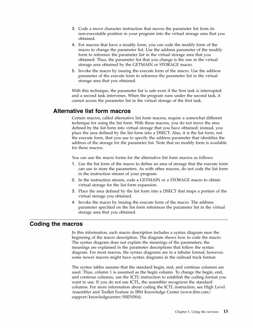
3. Code a move character instruction that moves the parameter list from itsnon-executable position in your program into the virtual storage area that youobtained.
4. For macros that have a modify form, you can code the modify form of themacro to change the parameter list. Use the address parameter of the modifyform to reference the parameter list in the virtual storage area that youobtained. Thus, the parameter list that you change is the one in the virtualstorage area obtained by the GETMAIN or STORAGE macro.
5. Invoke the macro by issuing the execute form of the macro. Use the addressparameter of the execute form to reference the parameter list in the virtualstorage area that you obtained.
With this technique, the parameter list is safe even if the first task is interruptedand a second task intervenes. When the program runs under the second task, itcannot access the parameter list in the virtual storage of the first task.
Alternative list form macrosCertain macros, called alternative list form macros, require a somewhat differenttechnique for using the list form. With these macros, you do not move the areadefined by the list form into virtual storage that you have obtained; instead, youplace the area defined by the list form into a DSECT. Also, it is the list form, notthe execute form, that you use to specify the address parameter that identifies theaddress of the storage for the parameter list. Note that no modify form is availablefor these macros.
You can use the macro forms for the alternative list form macros as follows:1. Use the list form of the macro to define an area of storage that the execute form
can use to store the parameters. As with other macros, do not code the list formin the instruction stream of your program.
2. In the instruction stream, code a GETMAIN or a STORAGE macro to obtainvirtual storage for the list form expansion.
3. Place the area defined by the list form into a DSECT that maps a portion of thevirtual storage you obtained.
4. Invoke the macro by issuing the execute form of the macro. The addressparameter specified on the list form references the parameter list in the virtualstorage area that you obtained.
Coding the macrosIn this information, each macro description includes a syntax diagram near thebeginning of the macro description. The diagram shows how to code the macro.The syntax diagram does not explain the meanings of the parameters; themeanings are explained in the parameter descriptions that follow the syntaxdiagram. For most macros, the syntax diagrams are in a tabular format; however,some newer macros might have syntax diagrams in the railroad track format.
The syntax tables assume that the standard begin, end, and continue columns areused. Thus, column 1 is assumed as the begin column. To change the begin, end,and continue columns, use the ICTL instruction to establish the coding format youwant to use. If you do not use ICTL, the assembler recognizes the standardcolumns. For more information about coding the ICTL instruction, see High LevelAssembler and Toolkit Feature in IBM Knowledge Center (www.ibm.com/support/knowledgecenter/SSENW6).
Chapter 1. Using the services 13

Figure 2 shows a sample macro called TEST and summarizes all the codinginformation that is available for it. The table is divided into three zones, A, B, andC.
v Column one of the table contains zones A and B. Zone A begins at the leftmargin; zone B is indented from the left margin by one or more blank spaces.Column two of the table contains zone C.
v Zone A and zone B contain those parameters that are allowed for the macro.Zone A contains those parameters that are required; zone B contains thoseparameters that are optional.
v If a parameter appears on a single line in the diagram (that is, a line whosepreceding line and following line are both blank), as shown in A1 and B1, thenthat is the only available choice for the particular parameter.
v If two or more parameters appear on adjacent lines (that is, with no interveningblank lines), as shown in A2 and B2, the parameters on those lines are mutuallyexclusive, that is, you can code any one of those parameters.
v A further distinction is made between mandatory and optional parameters. Theparameter descriptions that follow the syntax table clearly identify thoseparameters which are optional.
v Zone C (which is the second column in the syntax table), provides additionalinformation about coding the macro.
When substitution of a variable is indicated in zone C, the following classificationsare used:
A B C
A1
A2
B1
B2
name name:
TEST
b One or more blanks must precede TEST.
b One or more blanks must follow TEST.
MATH
HIST
GEOG
,DATA=
,LNG=
symbol. Begin in column 1.name
data length data length: symbol or decimal digit, with a maximum value of 256.
,FMT=HEX
,FMT=DEC
,FMT=BIN
Default: FMT=HEX
,PASS=
Default: PASS=65
,grade grade: symbol, decimal digit, or register (1) or (2) - (12).
symbol, decimal digit, or register (1) or (2) - (12).
RX-type address, or register (2) - (12)data addr data addr:
value value:
Figure 2. Sample tabular syntax diagram for the TEST macro
14 z/OS MVS Authorized Assembler Services Reference SET-WTO

VariableClassification
symbolAny symbol valid in the assembler language. The symbol can be as long asthe supported maximum length of a name entry in the assembler you areusing.
Decimal digitAny decimal digit up to and including the value indicated in theparameter description. If both symbol and decimal digit are indicated, anabsolute expression is also allowed.
Register (2) - (12)One of general purpose registers 2 through 12, specified withinparentheses, previously loaded with the right-adjusted value or addressindicated in the parameter description. You must set the unused high-orderbits to zero. You can designate the register symbolically or with anabsolute expression.
Register (0)General purpose register 0, previously loaded with the right-adjusted valueor address indicated in the parameter description. You must set the unusedhigh-order bits to zero. Designate the register as (0) only.
Register (1)General purpose register 1, previously loaded with the right-adjusted valueor address indicated in the parameter description. You must set the unusedhigh-order bits to zero. Designate the register as (1) only.
Register (15)General purpose register 15, previously loaded with the right-adjustedvalue or address indicated in the parameter description. You must set theunused high-order bits to zero. Designate the register as (15) only.
RX-type addressAny address that is valid in an RX-type instruction (for example, LA).
RS-type addressAny address that is valid in an RS-type instruction (for example, STM).
RS-type nameAny name that is valid in an RS-type instruction (for example, STM).
A-type addressAny address that can be written in an A-type address constant.
DefaultA value that is used in default of a specified value; that is, the value thesystem assumes if the parameter is not coded.
Rules for parameters: Use the parameters to specify the services and options tobe performed, and write them according to the following rules:v If the selected parameter is written in all capital letters (for example, MATH,
HIST, or FMT=HEX), code the parameter exactly as shown.v If the selected parameter is written in italics (for example, grade), substitute the
indicated value, address, or name.v If the selected parameter is a combination of capital letters and italics separated
by an equal sign (for example, DATA=data addr), code the capital letters andequal sign as shown, and then make the indicated substitution for the italicizedportion.
Chapter 1. Using the services 15

v Read the table from top to bottom.v Code commas and parentheses exactly as shown.v Positional parameters (parameters without equal signs) appear first; you must
code them in the order shown. You may code keyword parameters (parameterswith equal signs) in any order.
v If you select a parameter, read the second column (zone C) before proceeding tothe next parameter. The second column often contains coding restrictions for theparameter.
Continuation linesYou can continue the parameter field of a macro on one or more additional linesaccording to the following rules:v Enter a continuation character (not blank, and not part of the parameter coding)
in column 72 of the line.v Continue the parameter field on the next line, starting in column 16. All columns
to the left of column 16 must be blank.
You can code the parameter field being continued in one of two ways. Code theparameter field through column 71, with no blanks, and continue in column 16 ofthe next line; or truncate the parameter field by a comma, where a commanormally falls, with at least one blank before column 71, and then continue incolumn 16 of the next line. Figure 3 shows an example of each method.
Coding the callable servicesA callable service is a programming interface that uses the CALL macro to accesssystem services. To code a callable service, code the CALL macro followed by thename of the callable service, and a parameter list; for example:
CALL service,(parameter list)
The syntax diagram for the sample callable service SCORE:
Syntax Description
CALL SCORE
,(test_type,level,data,format_option,return_code)
NAME 1
NAME 2 OP2
OP1 OPERAND1,OPERAND2,OPERAND3,OPERAND4,OPERAND5,OPERAND6,OPX
ERAND7
OPERAND1,OPERAND2
OPERAND3,OPERAND4,
OPERAND5,OPERAND6,OPERAND7
THIS IS ONE WAY
THIS IS ANOTHER WAY XX
1 1610 44 72
Figure 3. Continuation Coding
16 z/OS MVS Authorized Assembler Services Reference SET-WTO

Considerations for coding callable services are:v You must code all the parameters in the parameter list because parameters are
positional in a callable service interface. That is, the function of each parameteris determined by its position with respect to the other parameters in the list.Omitting a parameter, therefore, assigns the omitted parameter's function to thenext parameter in the list.
v You must place values explicitly into all input parameters, because callableservices do not set default values.
v You can use the list and execute forms of the CALL macro to preserve yourprogram's reentrancy.
Including equate (EQU) statementsIBM supplies sets of equate (EQU) statements for use with some callable services.These statements, which you may optionally include in your source code, provideconstants for use in your program. IBM provides the statements as a programmingconvenience to save you the trouble of coding the definitions yourself.
Note: Check the “Programming Requirements” section of the individual servicedescription to determine if the equate statements are available for the callableservice you are using. If the equate statements are available, that section will alsoprovide a list of the statements that are provided, along with a description of howto include them in your program.
Link-editing linkage-assist routinesLinkage-assist routines provide the connection between your program and thesystem services that your program requests. When using callable services, link-editthe appropriate linkage-assist routines into your program module so that, duringexecution, the linkage-assist routines can resolve the address of, and pass controlto, the requested system services. You can also dynamically link to linkage-assistroutines as an alternative to link-editing. For example, issue the LOAD macro forthe linkage-assist routine, then issue a CALL to the loaded addresses.
To invoke the linkage-editor or binder, code JCL as in the following example:
Note: Omitting NCAL from the linkedit parameters (as the example shows) andspecifying SYS1.CSSLIB in the //SYSLIB statement, as shown, causes the addressesof all required linkage-assist routines to be automatically resolved. This statementsaves you the trouble of having to specify individual linkage-assist routines inINCLUDE statements.
//userid JOB ’accounting-info’,’name’,CLASS=x,// MSGCLASS=x,NOTIFY=userid,MSGLEVEL=(1,1),REGION=4096K//LINKSTEP EXEC PGM=HEWL,// PARM=’LIST,LET,XREF,REFR,RENT’//SYSPRINT DD SYSOUT=x//SYSLMOD DD DSN=userid.LOADLIB,DISP=OLD//SYSLIB DD DSN=SYS1.CSSLIB,DISP=SHR//OBJLIB DD DSN=userid.OBJLIB,DISP=SHR//SYSUT1 DD UNIT=SYSDA,SPACE=(TRK,(5,2))//SYSLIN DD *
INCLUDE OBJLIB(userpgm)ENTRY userpgmNAME userpgm(R)
/*
Chapter 1. Using the services 17

Service summaryTable 3 lists services described in the following:v z/OS MVS Programming: Authorized Assembler Services Reference ALE-DYNv z/OS MVS Programming: Authorized Assembler Services Reference EDT-IXGv z/OS MVS Programming: Authorized Assembler Services Reference LLA-SDUv z/OS MVS Programming: Authorized Assembler Services Reference SET-WTO.
For each service, the table indicates:v Whether a program in AR ASC mode can issue the servicev Whether a program in cross memory mode can issue the servicev Whether the macro checks the SYSSTATE global macro variablesv Whether the macro can be issued in 64-bit addressing mode
Note:
1. A program running in primary ASC mode when PASN=HASN=SASN can issueany of the services listed in the table.
2. Cross memory mode means that at least one of the following conditions is true:
PASN¬=SASNThe primary address space (PASN) and the secondary address space(SASN) are different.
PASN¬=HASNThe primary address space (PASN) and the home address space(HASN) are different.
SASN¬=HASNThe secondary address space (SASN) and the home address space(HASN) are different.
For more information about functions that are available to programs in crossmemory mode, see z/OS MVS Programming: Extended Addressability Guide.
3. Callable services do not check the SYSSTATE or SPLEVEL global variables.
Table 3. Service Summary
Service Can be issuedin AR ASCmode
Can be issuedin crossmemory mode
ChecksSYSSTATE
Can be issued in64-bit AMODE
ALESERV Yes Yes No No
ASCRE Yes Yes Yes No
ASDES Yes Yes Yes No
ASEXT Yes Yes No No
ATSET No Yes Yes No
ATTACH Yes (See note 1on page 26)
No Yes No
ATTACHX Yes No Yes Yes
AXEXT No Yes Yes No
AXFRE No Yes Yes No
AXRES No Yes Yes No
AXREXX No Yes Yes Yes
AXSET No Yes Yes No
BPXEKDA Yes No Yes No
18 z/OS MVS Authorized Assembler Services Reference SET-WTO
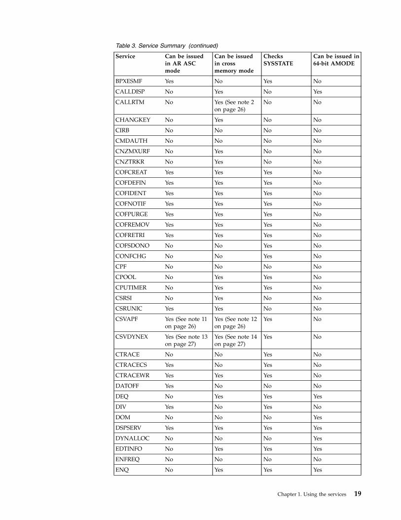
Table 3. Service Summary (continued)
Service Can be issuedin AR ASCmode
Can be issuedin crossmemory mode
ChecksSYSSTATE
Can be issued in64-bit AMODE
BPXESMF Yes No Yes No
CALLDISP No Yes No Yes
CALLRTM No Yes (See note 2on page 26)
No No
CHANGKEY No Yes No No
CIRB No No No No
CMDAUTH No No No No
CNZMXURF No Yes No No
CNZTRKR No Yes No No
COFCREAT Yes Yes Yes No
COFDEFIN Yes Yes Yes No
COFIDENT Yes Yes Yes No
COFNOTIF Yes Yes Yes No
COFPURGE Yes Yes Yes No
COFREMOV Yes Yes Yes No
COFRETRI Yes Yes Yes No
COFSDONO No No Yes No
CONFCHG No No Yes No
CPF No No No No
CPOOL No Yes Yes No
CPUTIMER No Yes Yes No
CSRSI No Yes No No
CSRUNIC Yes Yes No No
CSVAPF Yes (See note 11on page 26)
Yes (See note 12on page 26)
Yes No
CSVDYNEX Yes (See note 13on page 27)
Yes (See note 14on page 27)
Yes No
CTRACE No No Yes No
CTRACECS Yes No Yes No
CTRACEWR Yes Yes Yes No
DATOFF Yes No No No
DEQ No Yes Yes Yes
DIV Yes No Yes No
DOM No No No Yes
DSPSERV Yes Yes Yes Yes
DYNALLOC No No No Yes
EDTINFO No Yes Yes Yes
ENFREQ No No No No
ENQ No Yes Yes Yes
Chapter 1. Using the services 19

Table 3. Service Summary (continued)
Service Can be issuedin AR ASCmode
Can be issuedin crossmemory mode
ChecksSYSSTATE
Can be issued in64-bit AMODE
ESPIE No No No Yes
ESTAE (See note3 on page 26)
No No Yes No
ESTAEX Yes Yes Yes Yes
ETCON No Yes Yes No
ETCRE No Yes Yes No
ETDEF Yes Yes No No
ETDES No Yes Yes No
ETDIS No Yes Yes No
EVENTS No No No No
EXTRACT No No No No
FESTAE No No No No
FREEMAIN Yes (See note 4on page 26)
Yes Yes Yes
GETDSAB No No Yes No
GETMAIN Yes (See note 4on page 26)
Yes Yes Yes
GQSCAN No Yes No No
GTRACE No Yes No Yes
HSPSERV Yes Yes (See note 5on page 26)
(See note 6 onpage 26)
No
IARCP64 Yes Yes Yes Yes
IARR2V Yes Yes No No
IARSUBSP Yes Yes Yes No
IARST64 Yes Yes Yes Yes
IARVSERV Yes Yes Yes No
IARV64 Yes Yes Yes Yes
IAZXCTKN Yes Yes Yes No
IAZXJSAB Yes Yes (See note 15on page 27)
Yes No
IEAARR Yes Yes Yes Yes
IEAFP Yes Yes Yes No
IEALSQRY Yes Yes Yes No
IEAMETR Yes Yes Yes No
IEAMRMF3 No Yes No No
IEAMSCHD Yes Yes Yes No
IEANTCR Yes Yes N/A No
IEANTDL Yes Yes N/A No
IEANTRT Yes Yes N/A No
IEARBUP Yes Yes Yes No
20 z/OS MVS Authorized Assembler Services Reference SET-WTO

Table 3. Service Summary (continued)
Service Can be issuedin AR ASCmode
Can be issuedin crossmemory mode
ChecksSYSSTATE
Can be issued in64-bit AMODE
IEATDUMP Yes No Yes No
IEATEDS Yes Yes Yes No
IEATXDC Yes Yes Yes Yes
IEAVAPE No Yes No No
IEAVAPE2 No Yes No No
IEAVDPE No Yes No No
IEAVDPE2 No Yes No No
IEAVPSE No Yes No No
IEAVPSE2 No Yes No No
IEAVRLS No Yes No No
IEAVRLS2 No Yes No No
IEAVRPI No Yes No No
IEAVRPI2 No Yes No No
IEAVTPE No Yes No No
IEAVXFR No Yes No No
IEAVXFR2 No Yes No No
IEA4APE No Yes No Yes
IEA4APE2 No Yes No Yes
IEA4DPE No Yes No Yes
IEA4DPE2 No Yes No Yes
IEA4PSE No Yes No Yes
IEA4PSE2 No Yes No Yes
IEA4RLS No Yes No Yes
IEA4RLS2 No Yes No Yes
IEA4RPI No Yes No Yes
IEA4RPI2 No Yes No Yes
IEA4TPE No Yes No Yes
IEA4XFR No Yes No Yes
IEA4XFR2 No Yes No Yes
IEECMDS Yes Yes Yes No
IEEQEMCS Yes Yes Yes No
IEEVARYD No No Yes No
IEFPPSCN No No Yes No
IEFQMREQ No No No No
IEFSSI Yes No No No
IEFSSVT Yes No No No
IEFSSVTI Yes Yes No No
IFAQUERY Yes Yes No No
Chapter 1. Using the services 21

Table 3. Service Summary (continued)
Service Can be issuedin AR ASCmode
Can be issuedin crossmemory mode
ChecksSYSSTATE
Can be issued in64-bit AMODE
IOCINFO Yes Yes No No
IOSADMF No No Yes No
IOSCAPF No Yes (See note 7on page 26)
Yes No
IOSCAPU Yes Yes (See note 7on page 26)
Yes No
IOSCDR No No Yes No
IOSCHPD Yes Yes Yes No
IOSCMXA No Yes (See note 7on page 26)
Yes No
IOSCMXR No Yes (See note 7on page 26)
Yes No
IOSDCXR No Yes (See note 7on page 26)
Yes No
IOSENQ Yes Yes Yes No
IOSINFO No No No No
IOSLOOK No No No No
IOSPTHV No No Yes No
IOSSPOF No Yes Yes Yes
IOSUPFA No Yes Yes No
IOSUPFR No Yes Yes No
IOSVRYSW Yes Yes Yes No
IOSWITCH Yes Yes Yes No
IOSZHPF Yes Yes Yes No
IRDFSD Yes Yes Yes No
IRDFSDU Yes Yes Yes No
ISGADMIN Yes Yes Yes Yes
ISGECA Yes Yes Yes Yes
ISGENQ Yes Yes Yes Yes
ISGLCRT (Seenote 16 on page27)
No Yes N/A No
ISGLID (Seenote 16 on page27)
No Yes N/A Yes
ISGLOBT No Yes N/A No
ISGLREL No Yes N/A No
ISGLPRG No Yes N/A No
ISGQUERY Yes Yes Yes Yes
ITTFMTB No No No No
ITZXFILT No Yes Yes No
22 z/OS MVS Authorized Assembler Services Reference SET-WTO

Table 3. Service Summary (continued)
Service Can be issuedin AR ASCmode
Can be issuedin crossmemory mode
ChecksSYSSTATE
Can be issued in64-bit AMODE
IWMCLSFY No Yes Yes No
IWMCONN No Yes Yes No
IWMDISC No Yes Yes No
IWMECQRY No Yes Yes No
IWMECREA No Yes Yes No
IWMEDELE No Yes Yes No
IWMMABNL No Yes No No
IWMMCHST No Yes No No
IWMMCREA No Yes Yes No
IWMMDELE No Yes Yes No
IWMMEXTR No Yes Yes No
IWMMINIT No Yes No No
IWMMNTFY No Yes Yes No
IWMMRELA No Yes Yes No
IWMMSWCH No Yes Yes No
IWMMXFER No Yes No No
IWMPQRY Yes Yes Yes No
IWMRCOLL Yes Yes Yes No
IWMRPT No Yes Yes No
IWMRQRY Yes Yes Yes No
IWMSRDRS No Yes Yes No
IWMSRSRG No Yes Yes No
IWMSRSRS No Yes Yes No
IWMWMCON No Yes Yes No
IWMWQRY Yes Yes Yes No
IWMWQWRK No Yes Yes No
IXCCREAT Yes Yes Yes No
IXCDELET Yes Yes Yes No
IXCJOIN Yes No Yes No
IXCLEAVE Yes No Yes No
IXCMG Yes Yes Yes No
IXCMOD Yes Yes Yes No
IXCMSGI Yes No Yes No
IXCMSGO Yes Yes Yes No
IXCQUERY Yes Yes Yes No
IXCQUIES Yes No Yes No
IXCSETUS Yes Yes Yes No
IXCTERM Yes Yes Yes No
Chapter 1. Using the services 23

Table 3. Service Summary (continued)
Service Can be issuedin AR ASCmode
Can be issuedin crossmemory mode
ChecksSYSSTATE
Can be issued in64-bit AMODE
IXGBRWSE Yes Yes Yes Yes
IXGCONN Yes Yes Yes Yes
IXGDELET Yes Yes Yes Yes
IXGWRITE Yes Yes Yes Yes
LLACOPY No No Yes No
LOAD Yes No No Yes
LOADWAIT No Yes Yes No
LOCASCB Yes Yes Yes No
LXFRE No Yes Yes No
LXRES No Yes Yes No
MCSOPER Yes No Yes No
MCSOPMSG Yes No Yes No
MGCR No No No No
MGCRE No No No No
MIHQUERY Yes No Yes No
MODESET No Yes No Yes
NIL Yes Yes Yes No
NMLDEF No No No No
NUCLKUP No No No No
OIL Yes Yes Yes No
OUTADD No No No No
OUTDEL No No No No
PCLINK No Yes No No
PGANY No No No No
PGFIX No Yes No No
PGFIXA No No No No
PGFREE No Yes No No
PGFREEA No No No No
PGSER Yes (See note 8on page 26)
Yes (See note 8on page 26)
No Yes
POST No Yes No Yes
PTRACE No Yes No No
PURGEDQ No No No No
QEDIT No No No No
RESERVE No No No Yes
RESMGR Yes Yes No No
RESUME No Yes No No
RISGNL No Yes No No
SCHEDIRB Yes No Yes No
24 z/OS MVS Authorized Assembler Services Reference SET-WTO

Table 3. Service Summary (continued)
Service Can be issuedin AR ASCmode
Can be issuedin crossmemory mode
ChecksSYSSTATE
Can be issued in64-bit AMODE
SCHEDULE Yes Yes Yes No
SCHEDXIT No Yes No No
SDUMP Yes (See note 1on page 26)
Yes (See note 9on page 26)
Yes No
SDUMPX Yes Yes (See note 9on page 26)
Yes Yes
SETFRR Yes Yes Yes No
SETLOCK Yes Yes Yes No
SETRP Yes Yes Yes Yes
SJFREQ No Yes No No
SPIE No No No No
SPOST No No No No
SRBSTAT No Yes No No
SRBTIMER No No No No
STATUS Yes Yes No No
STORAGE Yes Yes No Yes
SUSPEND No Yes No No
SVCUPDTE No No No No
SWAREQ No No No No
SWBTUREQ No No No No
SYMREC No Yes Yes No
SYNCH Yes (See note 1on page 26)
No Yes No
SYNCHX Yes No Yes Yes
SYSEVENT No No No No
TCBTOKEN Yes Yes No No
TCTL No No No No
TESTAUTH No No No No
TIMEUSED Yes (See note 10on page 26)
Yes No Yes
T6EXIT No No No No
UCBINFO Yes Yes Yes No
UCBLOOK Yes Yes Yes No
UCBPIN Yes Yes Yes No
UCBSCAN Yes Yes Yes No
VSMLIST No Yes Yes No
VSMLOC No Yes Yes No
VSMREGN No Yes No No
WAIT No Yes No Yes
WTL No No No No
Chapter 1. Using the services 25

Table 3. Service Summary (continued)
Service Can be issuedin AR ASCmode
Can be issuedin crossmemory mode
ChecksSYSSTATE
Can be issued in64-bit AMODE
WTO No No No Yes
WTOR No No No Yes
Notes:
1. Primary mode callers can use either macro in the following macro pairs:v ATTACH or ATTACHXv SDUMP or SDUMPXv SYNCH or SYNCHXIBM recommends that programs in AR ASC mode use the X-macros(ATTACHX, SDUMPX, and SYNCHX). If, however, a program in AR modeissues ATTACH, SDUMP, or SYNCH after issuing SYSSTATE ASCENV=AR,the system substitutes the corresponding X-macro and issues a message tellingyou that it made the substitution.
2. CALLRTM TYPE=MEMTERM can be issued in cross memory mode. ForCALLRTM TYPE=ABTERM, see the CALLRTM macro description.
3. The only programs that can use ESTAE are programs that are in primarymode with (PASN=HASN=SASN).IBM recommends you always use ESTAEX unless your program and yourrecovery routine are in 24-bit addressing mode, or your program requires abranch entry. In these cases, you should use ESTAE.
4. IBM recommends that AR mode callers use the STORAGE macro instead ofusing GETMAIN or FREEMAIN.
5. For HSPSERV SREAD and HSPSERV SWRITE, PASN=HASN=SASN for anon-shared standard hiperspace for which an ALET is not used (that is, theHSPALET parameter is omitted).
6. If you use the HSPALET parameter, the HSPSERV macro checks SYSSTATE.7. If the input UCB is captured, the IOSCAPF, IOSCMXA, IOSCMXR, and
IOSDCXR macros can be issued in cross memory mode only if the UCB iscaptured in the primary address space. IOSCAPU CAPTOACT without theASID parameter also can be issued in cross memory mode if the UCB wascaptured in the primary address space. IOSCAPU CAPTUCB and IOSCAPUUCAPTUCB cannot be issued in cross memory mode.
8. PGSER can be issued in AR ASC mode only if you specify BRANCH=Y.PGSER can be issued in cross memory mode only if you specify BRANCH=Yor BRANCH=SPECIAL.
9. Both SDUMP and SDUMPX can be issued in cross memory mode only if youspecify BRANCH=YES.
10. Only TIMEUSED LINKAGE=SYSTEM can be issued in AR ASC mode.TIMEUSED LINKAGE=BRANCH cannot be issued in AR ASC mode.
11. For a QUERY request, CSVAPF can be issued only in primary mode. For allother requests, CSVAPF can be issued in primary or AR mode.
12. For CSVAPF with the ADD, DELETE, and DYNFORMAT requests, PASN =HASN = SASN. For CSVAPF with the QUERY, QUERYFORMAT, and LISTrequests, any PASN, any HASN, any SASN.
26 z/OS MVS Authorized Assembler Services Reference SET-WTO

13. For a QUERY or a CALL request with FASTPATH=YES, CSVDYNEX can beissued only in primary mode. For all other requests, CSVDYNEX can beissued in primary or AR mode.
14. For CSVDYNEX CALL, RECOVER, and QUERY requests, any PASN, anyHASN, any SASN. For all other requests, PASN=HASN=SASN.
15. When the caller of the IAZXJSAB macro specifies the ASCB parameter, anyPASN, any HASN, any SASN; otherwise, PASN=HASN is required.
16. The 64 bit entry names are as follows:v ISGLCR64v ISGLID64v ISGLOB64v ISGLRE64v ISGLPB64v ISGLPR64
Chapter 1. Using the services 27

28 z/OS MVS Authorized Assembler Services Reference SET-WTO

Chapter 2. SETFRR — Set up functional recovery routines
DescriptionThe SETFRR macro gives authorized programs the ability to define their recoveryin the FRR (functional recovery routine) LIFO stack, which is used duringprocessing of the system recovery manager. Any program function can use SETFRRto define its own unique recovery environment.
The SETFRR macro can be used to add, delete, or replace FRRs in the LIFO stack,or to purge all FRRs in the stack. The macro also optionally returns to the user theaddress of a parameter area that is eventually passed to the FRR when an erroroccurs. The parameter area can be used to keep information that might be useful tothe FRR. The recovery and retry routines execute in the same addressing mode asthe issuer of the macro.
z/OS MVS Programming: Authorized Assembler Services Guide describes the interfaceto an FRR and contains guidelines for writing an FRR.
EnvironmentThe requirements for the caller are:
Environmental factor RequirementMinimum authorization: Supervisor state and PSW key 0Dispatchable unit mode: Task or SRB (see note below)Cross memory mode: Any PASN, any HASN, any SASNAMODE: 24-bit, 31-bit, or 64-bitASC mode: Primary, in any AMODE
Secondary, in any AMODEAccess register (AR), in AMODE 24 or AMODE 31 only
Interrupt status: Enabled or disabled for I/O and external interrupts (seenote below)
Locks: The caller may hold locks, but is not required to hold any.(See note below.)
Control parameters: None.
Note: If the caller does not specify the EUT=YES parameter, the caller must be oneof the following:v Holding a lockv Disabled for I/O and external interruptsv In SRB mode.
Programming requirementsIf your program is in AR mode, issue the SYSSTATE ASCENV=AR macro beforeissuing SETFRR. SYSSTATE ASCENV=AR tells the system to generate codeappropriate for AR mode.
For primary mode callers, the parameter list you specify on the PARMADparameter must be in the primary address space. For AR mode callers, thisparameter list can be located in any address space.
© Copyright IBM Corp. 1988, 2017 29

The caller must include the following mapping macros:v IHAFRRSv IHAPSA
RestrictionsNone.
Input register informationBefore issuing the SETFRR macro, the caller does not have to place anyinformation into any register unless using it in register notation for a particularparameter, or using it as a base register.
Output register informationWhen control returns to the caller, the contents of the general purpose registers(GPRs) and access registers (ARs) are unchanged, with the exception of the GPRsyou specify on the WRKREGS parameter, which are used by the system.
Performance implicationsNone.
SyntaxThe SETFRR macro is written as follows:
Syntax Description
name name: Symbol. Begin name in column 1.
⌂ One or more blanks must precede SETFRR.
SETFRR
⌂ One or more blanks must follow SETFRR.
A,FRRAD=FRR addr FRR addr: A-type address, or register (2) - (12).
R,FRRAD=FRR addr
D
P
,WRKREGS=(reg1,reg2) reg1: Decimal digits 1-15.
reg2: Decimal digits 1-15.
,PARMAD=parm area addr parm area addr: A-type address, or register (2) - (12).
Note: This parameter may only be specified with A or R above.
,CANCEL=YES Default: CANCEL=YES
SETFRR macro
30 z/OS MVS Authorized Assembler Services Reference SET-WTO

Syntax Description
,CANCEL=NO
,EUT=YES
,MODE= Default: MODE=HOME
(
FULLXM
PRIMARY
HOME
,
LOCAL
)
,RELATED=value value: Any valid macro keyword specification.
,SDWALOC31=NO Default: SDWALOC31=NO
,SDWALOC31=YES
ParametersThe parameters are explained as follows:
A,FRRAD=FRRAD addrR,FRRAD=FRRAD addrDP Specifies the operation to be performed on the FRR LIFO stack:
A An FRR address is to be added to the stack.
R The FRR address last added to the stack is to be replaced by anotherFRR address.
D The FRR address last added to the stack is to be deleted.
P All entries in the stack are to be purged.
FRRAD specifies the address of a fullword containing the FRR address that isto be added or replaced. The parameter specifies the FRR address in a registeror specifies the address of a storage location containing the FRR address.
Note: When an FRR wants to deactivate itself, IBM recommends that the FRRissue SETRP with REMREC=YES rather than issuing SETFRR D. See thechapter on providing recovery in z/OS MVS Programming: Authorized AssemblerServices Guide for an explanation.
,WRKREGS=(reg1,reg2)Specifies two unique general purpose registers to be used as work registers bythe system.
,PARMAD=parm area addrSpecifies the address of a fullword to receive the address of the 24-byte
SETFRR macro
Chapter 2. SETFRR — Set up functional recovery routines 31

parameter area initialized to zeros and provided by the system to the issuer ofSETFRR. This 24-byte parameter area is in key 0 storage. If a register isspecified, the address of the 24-byte parameter area is placed in the register.This parameter area is associated with the FRR address that has either beenadded to or has replaced an FRR address on the stack. This parameter area ispassed to the FRR when an error occurs.
,CANCEL=YES,CANCEL=NO
Specifies whether you want to allow the recovery routine to be interrupted bycancel or detach processing.
To allow a recovery routine to be interrupted, specify CANCEL=YES.
To prevent a recovery routine from being interrupted, specify CANCEL=NO. Ifa cancel or detach is attempted against a recovery routine for which you havespecified CANCEL=NO, MVS defers cancel and detach processing until therecovery routine returns control to the system.
Note:
1. If a recovery routine that runs under the CANCEL=NO option can becalled by an unauthorized program running under the same task, IBMrecommends that you specify ASYNCH=NO for each ESTAE(X) macro thatthe recovery routine issues. This also includes any ESTAE(X) macros issuedby programs that the recovery routine calls.
2. If a recovery routine running under the CANCEL=NO option calls anunauthorized program, cancel and detach processing is also deferred forthe called program.
,EUT=YESUsed only with A and R, specifies that the new FRR can be used in anyenvironment. EUT=YES is used by routines that are not certain of theirenvironment; for example, a routine that can be called by an SRB or by a taskthat is executing enabled and might not hold any locks. While the FRR remainsin effect, no SVCs can be issued, no new asynchronous exits are dispatched,and no vector instructions can be executed.
,MODE=optionsSpecifies the environment in which the FRR is to get control and also,optionally, identifies the FRRs that free critical resources. The normal orexpected addressing environment is identified by FULLXM, PRIMARY, orHOME. Specify LOCAL to enable the FRR to be entered in a restrictedaddressing environment for freeing critical resources. Parentheses are notneeded if only one option is chosen.
FULLXMSpecifies that the FRR must be entered in the same cross memoryenvironment that existed when the SETFRR was issued.
PRIMARYSpecifies that the FRR must be entered in primary addressing mode withboth the PASID and SASID the same as the PASID that existed when theSETFRR was issued, the home address space must be unchanged, and thePSW key mask must be the same as when the SETFRR was issued.
HOMESpecifies that the FRR must be entered in primary addressing mode with
SETFRR macro
32 z/OS MVS Authorized Assembler Services Reference SET-WTO
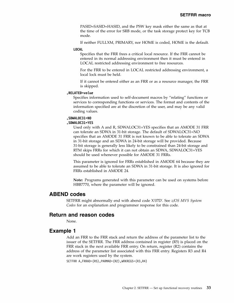
PASID=SASID=HASID, and the PSW key mask either the same as that atthe time of the error for SRB mode, or the task storage protect key for TCBmode.
If neither FULLXM, PRIMARY, nor HOME is coded, HOME is the default.
LOCALSpecifies that the FRR frees a critical local resource. If the FRR cannot beentered in its normal addressing environment then it must be entered inLOCAL restricted addressing environment to free resources.
For the FRR to be entered in LOCAL restricted addressing environment, alocal lock must be held.
If it cannot be entered either as an FRR or as a resource manager, the FRRis skipped.
,RELATED=valueSpecifies information used to self-document macros by “relating” functions orservices to corresponding functions or services. The format and contents of theinformation specified are at the discretion of the user, and may be any validcoding values.
,SDWALOC31=NO,SDWALOC31=YES
Used only with A and R, SDWALOC31=YES specifies that an AMODE 31 FRRcan tolerate an SDWA in 31-bit storage. The default of SDWALOC31=NOspecifies that an AMODE 31 FRR is not known to be able to tolerate an SDWAin 31-bit storage and an SDWA in 24-bit storage will be provided. Because31-bit storage is generally less likely to be constrained than 24-bit storage andRTM skips FRRs for which it can not obtain an SDWA, SDWALOC31=YESshould be used whenever possible for AMODE 31 FRRs.
This parameter is ignored for FRRs established in AMODE 64 because they areassumed to be able to tolerate an SDWA in 31-bit storage. It is also ignored forFRRs established in AMODE 24.
Note: Programs generated with this parameter can be used on systems beforeHBB7770, where the parameter will be ignored.
ABEND codesSETFRR might abnormally end with abend code X'07D'. See z/OS MVS SystemCodes for an explanation and programmer response for this code.
Return and reason codesNone.
Example 1Add an FRR to the FRR stack and return the address of the parameter list to theissuer of the SETFRR. The FRR address contained in register (R5) is placed on theFRR stack in the next available FRR entry. On return, register (R2) contains theaddress of the parameter list associated with this FRR entry. Registers R3 and R4are work registers used by the system.SETFRR A,FRRAD=(R5),PARMAD=(R2),WRKREGS=(R3,R4)
SETFRR macro
Chapter 2. SETFRR — Set up functional recovery routines 33

Example 2Delete the last FRR added to the FRR stack. Registers 1 and 6 are work registersused by the system.SETFRR D,WRKREGS=(1,6)
SETFRR macro
34 z/OS MVS Authorized Assembler Services Reference SET-WTO

Chapter 3. SETLOCK — Control access to serially reusableresources
DescriptionUse the SETLOCK macro to control access to serially reusable resources. Each kindof serially reusable resource is assigned a separate lock.
SETLOCK can do the following:v Obtain a specified lockv Release a specified lockv Test a specified lock or determine if the lock is held on the caller's processor.
Locks are discussed in the “Serialization” chapter in z/OS MVS Programming:Authorized Assembler Services Guide.
Note: The OBTAIN, RELEASE, and TEST options of the SETLOCK macro have thesame environmental specifications, programming requirements, restrictions, registerinformation, and performance implications described below, except where noted inthe explanations of each option.
EnvironmentThe requirements for the caller are:
Environmental factor RequirementMinimum authorization: Supervisor state, PSW key 0Dispatchable unit mode: Task or SRBCross memory mode: AnyAMODE: 24- or 31-bitASC mode: Primary or access register (AR)Interrupt status: Enabled or disabled for I/O and external interrupts. The
caller cannot be disabled when unconditionally requesting asuspend lock.
Locks: LOCAL or CML lock must be held to obtain the CMS lock;otherwise, the caller may hold locks, but is not required tohold any. Only locks lower in the hierarchy than the lockcurrently being requested may be held at the time ofinvocation.
Control parameters: None.
Programming requirementsv Before you invoke the SETLOCK macro in access register mode, issue SYSSTATE
ASCENV=AR.v The caller must include the IHAPSA mapping macro.v Before issuing an OBTAIN request for a CML lock, establish the target ASCB as
either the primary or secondary address space.
RestrictionsNone.
© Copyright IBM Corp. 1988, 2017 35

Input register informationBefore issuing the SETLOCK macro, the caller must ensure that the followinggeneral purpose register (GPR) contains the specified information:
RegisterContents
13 A 5-word save area if REGS=SAVE is specified, or an 18-word save area ifREGS=STDSAVE is specified.
Output register informationFor an OBTAIN or RELEASE request, when the REGS parameter is not specified,the contents of the general purpose registers (GPRs) after control returns to thecaller are as follows:
RegisterContents
0-10 Unchanged
11-12 Used as work registers by the system
13 Return code
14 Used as a work register by the system
15 Unchanged
For an OBTAIN or RELEASE request when the REGS parameter is specified, seethe description of the REGS parameter for information on GPR usage.
For a TEST request, the contents of the GPRs after control returns to the caller areas follows:
RegisterContents
0-1 Unchanged.
2-12 If one of these registers is specified on the LOCKHLD parameter, thatregister is used as a work register by the system; otherwise, registers 2-12are unchanged.
13-14 Unchanged.
When control returns to the caller, the access registers (ARs) contain:
RegisterContents
0-1 Used as work registers by the system
2-13 Unchanged
14-15 Used as work registers by the system
Some callers depend on register contents remaining the same before and afterissuing a service. If the system changes the contents of registers on which the callerdepends, the caller must save them before issuing the service, and restore themafter the system returns control.
SETLOCK macro
36 z/OS MVS Authorized Assembler Services Reference SET-WTO
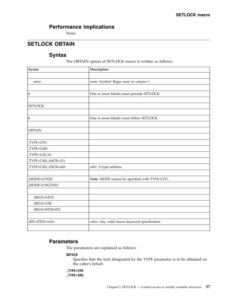
Performance implicationsNone.
SETLOCK OBTAIN
SyntaxThe OBTAIN option of SETLOCK macro is written as follows:
Syntax Description
name name: Symbol. Begin name in column 1.
� One or more blanks must precede SETLOCK.
SETLOCK
� One or more blanks must follow SETLOCK.
OBTAIN
,TYPE=CPU
,TYPE=CMS
,TYPE=LOCAL
,TYPE=CML,ASCB=(11)
,TYPE=CML,ASCB=addr addr: A-type address
,MODE=COND Note: MODE cannot be specified with TYPE=CPU.
,MODE=UNCOND
,REGS=SAVE
,REGS=USE
,REGS=STDSAVE
,RELATED=value value: Any valid macro keyword specification.
ParametersThe parameters are explained as follows:
OBTAINSpecifies that the lock designated by the TYPE parameter is to be obtained onthe caller's behalf.
,TYPE=CPU,TYPE=CMS
SETLOCK macro
Chapter 3. SETLOCK — Control access to serially reusable resources 37

,TYPE=LOCAL,TYPE=CML,ASCB=(11),TYPE=CML,ASCB=addr
Specifies the type of lock. The types available are:
CPU The processor lock. It is a pseudo spin lock providing MVS-recognizeddisablement. There is one CPU lock per processor and no processor canrequest another processor's lock. The lock is always available. Userscan obtain the CPU lock to become disabled for I/O and externalinterrupts.
CMS The cross memory services lock. It is a global suspend lock used toserialize functions between address spaces.
LOCALThe lock that serializes resources in the home address space pointed toby PSAAOLD. It is a local level suspend lock.
CML The cross memory local lock. It is a local level suspend type lock usedto serialize resources in an address space other than the home addressspace.
The requestor of a CML lock must have authority to access thespecified address space before requesting the lock. To establishauthority, the requestor sets the primary or secondary address space tothe one specified by the ASCB=(11) or ASCB=addr parameter. Register11 or addr must contain the address of the ASCB whose local lock isrequested. This address space must be nonswappable before theSETLOCK request.
Note: If the requestor specifies OBTAIN,TYPE=CML and the ASCBparameter points to the home address space, the request is treated asthough the LOCAL lock were being obtained.
,MODE=COND,MODE=UNCOND
Specifies whether the lock is to be conditionally or unconditionally obtained.
CONDSpecifies that the lock is to be conditionally obtained. That is, if thelock is not owned on another processor, it is acquired on the caller'sbehalf. If the lock is already held, control is returned indicating that thecaller holds the lock or that another unit of work on another processorowns the lock.
UNCONDSpecifies that the lock is to be unconditionally obtained. That is, if thelock is not owned on another processor, it is acquired on the caller'sbehalf. If the lock is already held by the caller, control is returned tothe calling program indicating that it already owns the lock. If the lockis held on another processor, the system suspends the SETLOCK calleruntil the lock is available.
The system does not permit an unconditional OBTAIN request for aCML lock if the lock is held by a unit of work that is setnondispatchable.
,REGS=SAVE,REGS=USE,REGS=STDSAVE
Specifies the use of general purpose registers by the SETLOCK macro.
SETLOCK macro
38 z/OS MVS Authorized Assembler Services Reference SET-WTO

SAVE Specifies that the contents of registers 11 through 14 are saved in thearea pointed to by register 13 and are restored upon completion of theSETLOCK request. This save area must be at least 20 bytes, and mustnot be the same area as the standard linkage save area used by theprogram.
Upon completion of the SETLOCK macro with REGS=SAVE, theregister contents are as follows:
RegisterContents
0-14 Unchanged
15 Return code
USE Specifies that the contents of registers 11 through 13 are saved in workregisters 0, 1, and 15.
Upon completion of the SETLOCK macro with REGS=USE, the registercontents are as follows:
RegisterContents
0-1 Used as work registers by the system
2-13 Unchanged
14 Used as a work register by the system
15 Return code
STDSAVESpecifies that the contents of registers 2 through 12 are saved in astandard 72-byte save area pointed to by register 13.
Upon completion of the SETLOCK macro with REGS=STDSAVE, theregister contents are as follows:
RegisterContents
0-1 Unchanged
2-13 Unchanged
14 Used as a work register by the system
15 Return code
Note: See “Output register information” on page 36 for information on registerusage when the REGS parameter is not specified.
,RELATED=valueSpecifies information used to self-document macros by “relating” functions orservices to corresponding functions or services. The format and contents of theinformation specified are at the discretion of the user, and may be any validcoding values.
ABEND codesSETLOCK might abnormally terminate with abend code X'073'. See z/OS MVSSystem Codes for an explanation and programmer response for this code.
SETLOCK macro
Chapter 3. SETLOCK — Control access to serially reusable resources 39

Return and reason codesWhen control returns to the caller, register 15 (or register 13, if the REGS parameteris not specified) contains one of the following hexadecimal return codes:
Table 4. Return Codes for the SETLOCK Macro
Return Code Meaning and Action
00 Meaning: The lock was successfully obtained.
Action: None.
04 Meaning: The lock was already held by the caller.
Action: None.
08 Meaning: The conditional obtain process was unsuccessful. The lock isowned by another processor.
Action: None required. However, you might try to take some action basedupon your application.
When the SETLOCK OBTAIN request is for the CPU lock, the system returns onlyreturn code 0. You do not need to check the return code because once control isreturned to you after the SETLOCK OBTAIN,TYPE=CPU request, you will havethe CPU lock.
Example 1Obtain the CPU lock, saving registers 2 through 12 in the standard save areawhose address is in register 13.SETLOCK OBTAIN,TYPE=CPU,REGS=STDSAVE
Example 2Obtain the CMS lock. Because the caller must hold the LOCAL or CML lock toobtain the CMS lock, the caller must first obtain the LOCAL lock unconditionally,saving registers 2 through 12 in the save area pointed to by register 13. The callerthen issues the request to obtain the CMS lock.SETLOCK OBTAIN,TYPE=LOCAL,MODE=UNCOND,REGS=STDSAVESETLOCK OBTAIN,TYPE=CMS,MODE=UNCOND,REGS=STDSAVE
Example 3Obtain the LOCAL lock unconditionally, saving registers 11 through 14 in the savearea pointed to by register 13. The save area pointed to by register 13 is not thesame area as the standard linkage save area.
LR 5,13 SAVE STANDARD SAVE AREA POINTERLA 13,SETLOCK_SAVEAREASETLOCK OBTAIN,TYPE=LOCAL,MODE=UNCOND,REGS=SAVELR 13,5 RESTORE STANDARD SAVE AREA POINTER...
SETLOCK_SAVEAREA DS 5F SAVE AREA FOR SETLOCK REQUESTS
SETLOCK macro
40 z/OS MVS Authorized Assembler Services Reference SET-WTO

SETLOCK RELEASE
SyntaxThe RELEASE option of the SETLOCK macro is written as follows:
Syntax Description
name name: Symbol. Begin name in column 1.
� One or more blanks must precede SETLOCK.
SETLOCK
� One or more blanks must follow SETLOCK.
RELEASE
,TYPE=CPU
,TYPE=CMS
,TYPE=LOCAL
,TYPE=CML,ASCB=(11)
,TYPE=CML,ASCB=addr addr: A-type address
,REGS=SAVE
,REGS=USE
,REGS=STDSAVE
,RELATED=value value: Any valid macro keyword specification.
ParametersThe parameters are explained as follows:
RELEASESpecifies that the lock designated by the TYPE parameter is to be released.
Note: If you specify RELEASE,TYPE=CML,ASCB=(11) or ASCB=addr, theASCB parameter specifies the home address space, and the lock that the callerholds is home's local lock, then SETLOCK processing treats the CML releaserequest as a RELEASE, TYPE=LOCAL.
,TYPE=CPU,TYPE=CMS,TYPE=LOCAL,TYPE=CML,ASCB=(11),TYPE=CML,ASCB=addr
Specifies the type of lock. The types available are:
SETLOCK macro
Chapter 3. SETLOCK — Control access to serially reusable resources 41

CPU The processor lock. It is a pseudo spin lock providing MVS-recognizeddisablement. There is one CPU lock per processor and no processor canrequest another processor's lock. The lock is always available. Userscan obtain the CPU lock to become disabled for I/O and externalinterrupts.
CMS The cross memory services lock. It is a global suspend lock used toserialize functions between address spaces.
LOCALThe lock that serializes resources in the home address space pointed toby PSAAOLD. It is a local level suspend lock.
CML The cross memory local lock. It is a local level suspend type lock usedto serialize resources in an address space other than the home addressspace.
The requestor of a CML lock must have authority to access thespecified address space before requesting the lock. To establishauthority, the requestor sets the primary or secondary address space tothe one specified by the ASCB=(11) or ASCB=addr parameter. Register11 or addr must contain the address of the ASCB whose local lock isrequested. This address space must be nonswappable before theSETLOCK request.
Note: If the requestor specifies OBTAIN,TYPE=CML and the ASCBparameter points to the home address space, the request is treated asthough the LOCAL lock were being obtained.
,REGS=SAVE,REGS=USE,REGS=STDSAVE
Specifies the use of general purpose registers by the SETLOCK macro.
SAVE Specifies that the contents of registers 11 through 14 are saved in thearea pointed to by register 13 and are restored upon completion of theSETLOCK request. This save area must be at least 20 bytes, and mustnot be the same area as the standard linkage save area used by theprogram.
Upon completion of the SETLOCK macro with REGS=SAVE, theregister contents are as follows:
RegisterContents
0-14 Unchanged
15 Return code
USE Specifies that the contents of registers 11 through 13 are saved in workregisters 0, 1, and 15.
Upon completion of the SETLOCK macro with REGS=USE, the registercontents are as follows:
RegisterContents
0-1 Used as work registers by the system
2-13 Unchanged
14 Used as a work register by the system
SETLOCK macro
42 z/OS MVS Authorized Assembler Services Reference SET-WTO
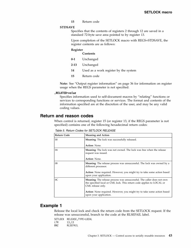
15 Return code
STDSAVESpecifies that the contents of registers 2 through 12 are saved in astandard 72-byte save area pointed to by register 13.
Upon completion of the SETLOCK macro with REGS=STDSAVE, theregister contents are as follows:
RegisterContents
0-1 Unchanged
2-13 Unchanged
14 Used as a work register by the system
15 Return code
Note: See “Output register information” on page 36 for information on registerusage when the REGS parameter is not specified.
,RELATED=valueSpecifies information used to self-document macros by “relating” functions orservices to corresponding functions or services. The format and contents of theinformation specified are at the discretion of the user, and may be any validcoding values.
Return and reason codesWhen control is returned, register 15 (or register 13, if the REGS parameter is notspecified) contains one of the following hexadecimal return codes:
Table 5. Return Codes for SETLOCK RELEASE
Return Code Meaning and Action
00 Meaning: The lock was successfully released.
Action: None.
04 Meaning: The lock was not owned. The lock was free when the releaserequest was issued.
Action: None.
08 Meaning: The release process was unsuccessful. The lock was owned by adifferent processor.
Action: None required. However, you might try to take some action basedupon your application.
0C Meaning: The release process was unsuccessful. The caller does not ownthe specified local or CML lock. This return code applies to LOCAL orCML release only.
Action: None required. However, you might try to take some action basedupon your application.
Example 1Release the local lock and check the return code from the SETLOCK request. If therelease was unsuccessful, branch to the code at the RLSEFAIL label.SETLOCK RELEASE,TYPE=LOCALLTR 13,13BNZ RLSEFAIL
SETLOCK macro
Chapter 3. SETLOCK — Control access to serially reusable resources 43

Example 2Release the CML lock, saving the contents of registers 2 through 12 in a standardsave area. Check the return code from the SETLOCK request, and branch to thecode at the RLSEFAIL label if the release was unsuccessful.SETLOCK RELEASE,TYPE=CML,REGS=STDSAVELTR 15,15BNZ RLSEFAIL
SETLOCK TEST
SyntaxThe TEST option of the SETLOCK macro is written as follows:
Syntax Description
name name: Symbol. Begin name in column 1.
� One or more blanks must precede SETLOCK.
SETLOCK
� One or more blanks must follow SETLOCK.
TEST
,TYPE=CPU
,TYPE=CMS
,TYPE=LOCAL
,TYPE=ALOCAL
,TYPE=CML Note: LOCKHLD or ASCB must be specified with TYPE=CML.
,LOCKHLD=(reg) reg: Register (2) - (12)
Note: LOCKHLD is valid only with TYPE=CML, TYPE=ALOCAL, andTYPE=CPU
,ASCB=(reg) reg: Register (2) - (12)
Note: ASCB is valid only with TYPE=CML.
,BRANCH=(HELD,addr) addr: RX-type address.
,BRANCH=(NOTHELD,addr)
,RELATED=value value: Any valid macro keyword specification.
SETLOCK macro
44 z/OS MVS Authorized Assembler Services Reference SET-WTO

ParametersThe parameters are explained as follows:
TESTSpecifies that the lock designated by the TYPE parameter is to be checked todetermine if it is currently held on the requesting processor.
,TYPE=CPU,TYPE=CMS,TYPE=LOCAL,TYPE=ALOCAL,TYPE=CML
Specifies the type of lock. The types available are:
CPU The processor lock. It is a pseudo spin lock providing MVS-recognizeddisablement. There is one CPU lock per processor, and no processorcan request another processor's lock. The lock is always available.Users can obtain the CPU lock to become disabled for I/O andexternal interrupts.
CMS The cross memory services lock. It is a global suspend lock used toserialize functions between address spaces.
LOCALThe lock that serializes resources in the home address space pointed toby PSAAOLD. It is a local level suspend lock.
ALOCALDetermines whether a local lock is held, either home's LOCAL lock ora CML lock. The LOCKHELD=(reg) parameter can be specified withTYPE=ALOCAL.
CML The cross memory local lock. It is a local level suspend type lock usedto serialize resources in an address space other than the home addressspace. TYPE=CML specifies that the caller wishes to determinewhether a CML lock is held. Either the ASCB=(reg) or theLOCKHLD=(reg) parameter can be specified with TYPE=CML, but notboth.
,LOCKHLD=(reg)Specifies that the designated register is to be used as a return register by themacro. This parameter is valid only for TYPE=CML, TYPE=CPU, andTYPE=ALOCAL.
If TYPE=CML is specified and a CML lock is held, the system returns theASCB address of the CML-locked address space in the specified register.
If TYPE=CPU is specified, the system returns the current CPU lock use countfor this processor in the specified register.
If TYPE=ALOCAL is specified and the LOCAL lock is held, the system returnsa zero in the specified register.
If TYPE=ALOCAL is specified and a CML lock is held, the system returns theASCB address of the CML-locked address space in the specified register.
,ASCB=(reg)Specifies a register that contains the ASCB address. The system checks theASCB to determine whether the requestor's local lock is a CML lock. Thisparameter is valid only with TYPE=CML.
SETLOCK macro
Chapter 3. SETLOCK — Control access to serially reusable resources 45

Note: Unlike the OBTAIN and RELEASE options of the SETLOCK macro,ASCB=addr is not valid.
,BRANCH=(HELD,addr),BRANCH=(NOTHELD,addr)
If (HELD,addr) is specified, the specified address is branched to if the specifiedlock is held on the requesting processor.
If (NOTHELD,addr) is specified, the specified address is branched to if thespecified lock is not currently held on the requesting processor.
,RELATED=valueSpecifies information used to self-document macros by “relating” functions orservices to corresponding functions or services. The format and contents of theinformation specified are at the discretion of the user, and may be any validcoding values.
Return and reason codesWhen control is returned, register 15 contains one of the following hexadecimalreturn codes (if the BRANCH= parameter was omitted):
Table 6. Return Codes for SETLOCK TEST
Return Code Meaning and Action
00 Meaning: The lock was held by the requestor, or (if TYPE=CMS wasspecified) at least one lock was held.
Action: None.
04 Meaning: The lock was available, or (if TYPE=CMS was specified) no lockwas held.
Action: None.
Note: TYPE=CMS is used to determine if at least one cross memory services lockis held, but cannot be used to determine which one, or to determine if all are held.
Example 1If a local lock is not held, branch to DSRLLINT; otherwise, execute the nextsequential instruction.SETLOCK TEST,TYPE=LOCAL,BRANCH=(NOTHELD,DSRLLINT)
Example 2Put the current CPU lock use count for this processor into register 3.SETLOCK TEST,TYPE=CPU,LOCKHLD=(3)
Example 3Determine whether the local lock of the address space specified in register 11 isheld as a CML lock.SETLOCK TEST,TYPE=CML,ASCB=(11)
SETLOCK macro
46 z/OS MVS Authorized Assembler Services Reference SET-WTO

Chapter 4. SETRP — Set return parameters
DescriptionUse the SETRP macro within a recovery routine to indicate the various requeststhat the recovery routine can make. SETRP is valid for functional recovery routines(FRRs) and ESTAE-type recovery routines. For more information about recoveryroutines, see the information on providing recovery in z/OS MVS Programming:Authorized Assembler Services Guide.
The SETRP macro is also described in z/OS MVS Programming: Assembler ServicesReference ABE-HSP with the exception of the RECORD, FRELOCK, SERIAL,RETRY, RETRY15, FRLKRTY, and SSRESET parameters.
EnvironmentThe requirements for the caller are:
Environmental factor RequirementMinimum authorization: Problem state and any PSW key. For the FRELOCK, SERIAL,
RETRY, RETRY15, and FRLKRTY parameters, supervisorstate or PSW key 0-7.
Dispatchable unit mode: Task or SRBCross memory mode: Any PASN, any HASN, any SASNAMODE: 24- or 31- or 64-bit
Note: For the DUMPOPX parameter, AMODE=64 is notallowed.
ASC mode: Primary, secondary, or access register (AR)Note: Callers in secondary ASC mode cannot specify theDUMPOPX keyword.
Interrupt status: Enabled or disabled for I/O and external interruptsLocks: The caller may hold locks, but is not required to hold any.Control parameters: None.
Programming requirementsv If the program is in AR mode, issue the SYSSTATE ASCENV=AR macro before
SETRP. SYSSTATE ASCENV=AR tells the system to generate code appropriatefor AR mode.
v Include the IHASDWA mapping macro to map the system diagnostic work area(SDWA). The SDWA is addressable when the recovery routine is entered; whenthe SETRP macro is issued, the same address space must be addressable. (SeeSDWA in z/OS MVS Data Areas in the z/OS Internet library(www.ibm.com/systems/z/os/zos/library/bkserv) for the mapping providedby IHASDWA.)
v If you plan to specify RETREGS=YES,RUB=reg info addr, you must obtain storagefor and initialize the register update block (RUB). See the RETREGS parameterdescription for more information about this area.
Restrictionsv You can use SETRP only if the system provided an SDWA.
© Copyright IBM Corp. 1988, 2017 47

v Recovery routines established through the STAE macro, or the STAI parameteron the ATTACH or ATTACHX macro, cannot update registers on retry, so theRETREGS parameter does not apply.
v For FRRs, RETREGS=YES (or RETREGS=NO) has no effect. For FRRs, the systemalways restores GPRs 0-14 from the SDWASRSV field, and ARs 0-14 from theSDWAARSV field. If you specify RETRY15=YES, the system also restores GPR 15and AR 15 from the SDWASRSV and SDWAARSV fields, respectively.
Input register informationBefore issuing the SETRP macro, the caller must ensure that the following generalpurpose registers (GPRs) contain the specified information:
RegisterContents
1 If you do not specify the WKAREA parameter, address of the SDWA;otherwise, the caller does not have to place any information into thisregister.
13 If you specify the REGS parameter, address of a standard 72-byte save areacontaining the registers to be restored; otherwise, the caller does not haveto place any information into this register.
Before issuing the SETRP macro, the caller must ensure that the following accessregisters (ARs) contain the specified information:
RegisterContents
1 If you do not specify the WKAREA parameter, ALET of the SDWA whoseaddress is in GPR 1; otherwise, the caller does not have to place anyinformation into this register.
13 If you specify the REGS parameter, ALET of the standard 72-byte save areawhose address is in GPR 13; otherwise, the caller does not have to placeany information into this register.
Output register informationWhen control returns to the caller, the general purpose registers (GPRs) contain:
RegisterContents
0-1 Used as work registers by the system
2-13 Unchanged
14-15 Used as work registers by the system
When control returns to the caller, the access registers (ARs) contain:
RegisterContents
0-1 Used as work registers by the system
2-13 Unchanged
14-15 Used as work registers by the system
Note: Control does not return to the caller if the caller specifies the REGSparameter.
SETRP macro
48 z/OS MVS Authorized Assembler Services Reference SET-WTO

Some callers depend on register contents remaining the same before and afterissuing a service. If the system changes the contents of registers on which the callerdepends, the caller must save them before issuing the service, and restore themafter the system returns control.
Performance implicationsNone.
SyntaxThe SETRP macro is written as follows:
Syntax Description
name name: Symbol. Begin name in column 1.
� One or more blanks must precede SETRP.
SETRP
� One or more blanks must follow SETRP.
WKAREA=(reg) reg: Decimal digits 1-12.
Default: WKAREA=(1)
,REGS=(reg1) reg1: Decimal digits 0-12, 14, 15.
,REGS=(reg1,reg2) reg2: Decimal digits 0-12, 14, 15.
Note: If you specify (reg1,reg2), specify the registers in the same order as inan STM instruction; for example, to restore all registers except register 13,specify REGS=(14,12).
,DUMP=IGNORE Default: DUMP=IGNORE
,DUMP=YES
,DUMP=NO
,DUMPOPT=parm list addr parm list addr: RX-type address, or register (2) - (12).
,DUMPOPX=parm list addr Note: Specify these parameters only if you specify DUMP=YES.
,RC=0 Default: RC=0
,RC=4
,RC=16
,RETADDR=retry addr retry addr: RX-type address, or register (2) - (12).
Note: This parameter may be specified only if RC=4 is specified above.
,RETREGS=NO info addr: RX-type address, or register (2) - (12).
SETRP macro
Chapter 4. SETRP — Set return parameters 49

Syntax Description
,RETREGS=YES Default: RETREGS=NO
,RETREGS=YES,RUB=info addr Note: This parameter may be specified only if RC=4 is specified above.
,RETREGS=64
,FRESDWA=NO Default: FRESDWA=NO
,FRESDWA=YES Note: This parameter may be specified only if RC=4 is specified above.
,COMPCOD=code1 code1: Symbol or decimal number.
,COMPCOD=(code) code: Symbol, decimal number, or register (2) - (12).
,COMPCOD=(code, USER) Default: COMPCOD=(code,USER)
,COMPCOD=(code,SYSTEM)
,FRELOCK=(locks) locks: Any combination of the following, separated by commas:
CPU CMS
LOCALCML(cmlascb)
cmlascb: RX-type address or register (2) - (12).
,REASON=code code: Symbol, decimal or hexadecimal number, or register (2) - (12).
,RECORD=IGNORE Default: RECORD=IGNORE
,RECORD=YES
,RECORD=NO
,RECPARM=record list addr record list addr: RX=type address, or register (2) - (12).
Note: This parameter may be specified only if RECORD=IGNORE orRECORD=YES is specified above.
,SERIAL=YES
,SERIAL=NO
,RETRY=FRR Default: RETRY=FRR
,RETRY=ERROR
,RETRY15=NO Default: RETRY15=NO
,RETRY15=YES
,REMREC=NO Default: REMREC=NO
,REMREC=YES
SETRP macro
50 z/OS MVS Authorized Assembler Services Reference SET-WTO

Syntax Description
,FRLKRTY=NO Default: FRLKRTY=NO
,FRLKRTY=YES
,SSRESET=YES
,SSRESET=NO
,RETRYAMODE=amode amode: decimal 24, 31, or 64. Only honored for ARR, ESTAE, ESTAI,ESTAEX, FESTAE, FRR and IEAARR recovery routines.
ParametersThe parameters are explained below:
WKAREA=(reg) Specifies the address of the SDWA passed to the recovery routine. If thisparameter is omitted, the address of the SDWA must be in register 1.
,REGS=(reg 1) ,REGS=(reg 2)
Specifies the register or range of registers to be restored from the 72-bytestandard save area pointed to by the address in register 13. If you specifyREGS, a branch on register 14 instruction will also be generated to returncontrol to the system. If you do not specify REGS, you must code your ownbranch on whichever register contains the return address.
Note: If you specify reg1,reg2, specify the registers in the same order as in anSTM instruction; for example, to restore all registers except register 13, specifyREGS=(14,12).
,DUMP=IGNORE ,DUMP=YES ,DUMP=NO
Specifies that the dump option fields will not be changed (IGNORE), will bezeroed (NO), or will be merged with dump options specified in previousdump requests, if any (YES). If IGNORE is specified, a previous recoveryroutine had requested a dump or a dump had been requested through theABEND macro, and the previous request will remain intact. If NO is specified,no dump will be taken.
DUMP=YES does not guarantee that a SYSABEND/SYSUDUMP will be taken.You may specify this request in an FRR for an SRB but you will get anabdump only if the SRB abend successfully percolates to a task and none of theFRRs for that task choose to retry and the final value of the DUMP= remainsthe same after every recovery routine has received control.
,DUMPOPT=parm list addr,DUMPOPX=parm list addr
Specifies the address of a parameter list of dump options. You can create theparameter list through the list form of the SNAP or SNAPX macro, or you cancreate a compatible list. DUMPOPT specifies the address of a parameter listthat the SNAP macro creates. DUMPOPX specifies the address of a parameterlist that the SNAPX macro creates. A program in secondary mode cannot usethe DUMPOPX parameter.
SETRP macro
Chapter 4. SETRP — Set return parameters 51

If the specified dump options include subpools for storage areas to bedumped, up to seven subpools can be dumped. Subpool areas are accumulatedand wrapped, so that the eighth subpool area specified replaces the first.
If the dump options specified include ranges of storage areas to be dumped,only the storage areas in the first thirty ranges will be dumped.
The TCB, DCB, ID, and STRHDR options available on SNAP or SNAPX areignored if they appear in the parameter list. The TCB used will be the one forthe task that encountered the error. The DCB used will be one created by thesystem, and either SYSABEND, SYSMDUMP, or SYSUDUMP will be used as aDDNAME.
,REASON=codeSpecifies the reason code that the user wishes to pass to subsequent recoveryroutines. The value range for code is any 32-bit hexadecimal number or 31-bitdecimal number. See z/OS MVS Programming: Assembler Services ReferenceABE-HSP for information about how a user can change this code.
,RC=0 ,RC=4 ,RC=16
Specifies the return code the recovery routine sends to the system to indicatewhat further action is required:
Decimal CodeMeaning
0 Continue with error processing; causes entry into previously-specifiedrecovery routine, if any.
4 Retry using the retry address specified.
16 Valid only for an ESTAI/STAI recovery routine. The system should notgive control to any further ESTAI/STAI routines, and shouldabnormally end the task.
,RETADDR=retry addrSpecifies the address of the retry routine to which control is to be given.
,RETREGS=NO ,RETREGS=YES ,RETREGS=YES ,RUB=reg info addr,RETREGS=64
Specifies the contents of the registers to be restored on entry to the retryroutine. RETREGS=NO indicates that you do not want the system to restoreany register contents from the SDWA.
If you specify RETREGS=YES, in a recovery routine defined through theESTAE, ESTAEX, or FESTAE macro, the ESTAI parameter on the ATTACH orATTACHX macro, or an associated recovery routine (ARR), the system doesthe following:v Initializes GPRs 0-15 from the SDWASRSV field of the SDWAv Initializes ARs 0-15 from the SDWAARSV field of the SDWA.
Specifying RETREGS=64 is the same as specifying RETREGS=YES, except theregisters for retry are the 64-bit general purpose registers in field SDWAG64.
RUB (register update block) specifies the address of an area that containsregister update information for the GPRs. The data you specify in this area willbe moved into the SDWASRSV field of the SDWA and will be loaded into theGPRs on entry to the retry routine. You cannot use the RUB to specify data to
SETRP macro
52 z/OS MVS Authorized Assembler Services Reference SET-WTO

be moved into the SDWAARSV field for loading the ARs. You can use the RUBfor both ESTAE-type recovery routines and FRRs. The maximum length of theRUB is 66 bytes. You must acquire storage for and initialize this area asfollows:v The first two bytes represent the registers to be updated, register 0
corresponding to bit 0, register 1 corresponding to bit 1, and so on. The userindicates which of the registers are to be stored in the SDWA by setting thecorresponding bits in these two bytes.
v The remaining 64 bytes contain the update information for the registers, inthe order 0-15. If all 16 registers are being updated, this field consists of 64bytes. If only one register is being updated, this field consists of only 4 bytesfor that one register.
For example, if only registers 4, 6, and 9 are being updated:v Bits 4, 6, and 9 of the first two bytes are set.v The remaining field consists of 12 bytes for registers 4, 6, and 9; the first 4
bytes are for register 4, followed by 4 bytes for register 6, and 4 final bytesfor register 9.
,FRESDWA=NO,FRESDWA=YES
Specifies that the entire SDWA be freed (YES) or not be freed (NO) before entryinto the retry routine.
,COMPCOD=code1,COMPCOD=(code),COMPCOD=(code,USER),COMPCOD=(code,SYSTEM)
Specifies the user or system completion code that the user wants to pass tosubsequent recovery routines.
,FRELOCK=(locks)Specifies the locks to be freed and the corresponding lockwords that are placedin the SDWA:
CPU Processor lock
CMS Cross memory services lock
LOCALStorage lock of the storage the caller is executing in
CML(cmlascb)Cross memory local lock, where cmlascb indicates the ASCB address ofthe address space for which the local lock is to be freed
Note: If FRLKRTY=NO is specified or taken as a default, the specified locksare freed only on percolation, not on retry. Specifying FRLKRTY=YES allowsthe locks listed in FRELOCK to be freed on retry.
,RECORD=IGNORE,RECORD=YES,RECORD=NO
Specifies whether the SDWA is to be recorded in SYS1.LOGREC(RECORD=YES/NO), or whether the system should honor previousinstructions about recording the SDWA in SYS1.LOGREC (RECORD=IGNORE).
If you specify RECORD=YES, the system records the entire SDWA (includingthe fixed length base, the variable length recording area, and the recordable
SETRP macro
Chapter 4. SETRP — Set return parameters 53

extensions) in SYS1.LOGREC when the ESTAE recovery routine returns control,even if the mainline program issued the ESTAE or ESTAEX macro withRECORD=NO.
If you specify RECORD=NO, the system does not record the SDWA inSYS1.LOGREC, even if the mainline program issued ESTAE or ESTAEX withRECORD=YES.
If you specify RECORD=IGNORE, the system honors the request as specifiedby the RECORD parameter on the ESTAE or ESTAEX macro.
,RECPARM=record list addrSpecifies the address of a user-supplied record parameter list used to updatethe SDWA with recording information. The parameter list consists of three8-byte fields:v The first field contains the load module name.v The second field contains the CSECT name (assembly module name).v The third field contains the recovery routine name (assembly module name).
If the recovery routine label is not the same as the assembly module name,the label can be used.
The three fields are left-justified, and padded with blanks.
,SERIAL=YES,SERIAL=NO
Specifies whether the percolation from an SRB mode FRR to a related taskrecovery routine (ESTAE or FRR) is to be serialized (YES) or not serialized(NO) with respect to unlocked task recovery. See 'SRB to Task Percolation' inz/OS MVS Programming: Authorized Assembler Services Guide.
If the task is already in recovery for another error when SERIAL=YES isspecified, the percolation request is deferred pending a requested task retryfrom any recovery routine covering mainline code. If such a retry is notrequested, the task is terminated and all deferred percolations are purged.Only the last FRR to receive control when an error occurs can specifySERIAL=YES.
,RETRY=FRR,RETRY=ERROR
Specifies the cross memory environment in which the retry routine getscontrol.
RETRY=FRR, the default, specifies that the retry routine gets control in thecross memory environment that exists at the time of entry to the FRR.
RETRY=ERROR specifies that the retry routine gets control in the crossmemory environment that existed at the time of the error. Do not specifyRETRY=ERROR if the cross memory status at the time of the error is notavailable, that is, if SDWARPIV is set to one. (Be careful not to create a loop byretrying to an erroneous cross memory state with RETRY=ERROR.)
,RETRY15=YES,RETRY15=NO
In an FRR environment only, specifies that GPR 15 is restored fromSDWASRSV and AR 15 is restored from SDWAARSV if RETRY15=YES.Otherwise, it contains the entry point address of the retry routine.
This parameter may be specified only when RC=4 is specified. IfRETRY15=YES is not coded on any SETRP invocation prior to returning to thesystem, the effect is that of specifying RETRY15=NO.
SETRP macro
54 z/OS MVS Authorized Assembler Services Reference SET-WTO

,REMREC=YES,REMREC=NO
In an FRR or ESTAE environment, specifies that the FRR/ESTAE entry for thecurrently running FRR/ESTAE routine be removed (REMREC=YES) or notremoved (REMREC=NO). This parameter may be specified only when RC=4 isspecified, indicating a retry request.
The entry is removed before control returns to the retry point. If REMREC=YESis not coded on any SETRP invocation before the system receives control, theeffect is that of specifying REMREC=NO. The REMREC parameter may beused to remove a recovery routine that has been defined with a token,although the token cannot be specified when you code the SETRP macro.
,FRLKRTY=YES,FRLKRTY=NO
In an FRR environment only, specifies that the locks specified on FRELOCK befreed (FRLKRTY=YES) or not be freed (FRLKRTY=NO) on retry.
This parameter may be specified only when RC=4 is specified. IfFRLKRTY=YES is not coded on any SETRP invocation prior to returning to thesystem, the effect is that of specifying FRLKRTY=NO.
SSRESET=YESSSRESET=NO
SSRESET=YES specifies that, if the current recovery routine abnormally ends,the next recovery routine is to get control in the subspace environment thatexisted when the current recovery routine was entered. Specify SSRESET=YESwhen the current recovery routine has temporarily modified the subspaceenvironment, and when it is appropriate for the next recovery routine toreceive control in the subspace environment in which the current recoveryroutine received control.
SSRESET=NO negates an earlier specification of SSRESET=YES. SpecifySSRESET=NO when SSRESET=YES protection is no longer needed. If thecurrent recovery routine abnormally ends after specifying SSRESET=NO, thenext recovery routine will get control in the subspace in which the currentroutine was running when the error occurred.
If you do not specify SSRESET and the current recovery routine abnormallyends, the next recovery routine will get control in the subspace in which thecurrent recovery routine was running when the error occurred.
See the chapter on subspaces in z/OS MVS Programming: Extended AddressabilityGuide for more information about subspaces and recovery.
,RETRYAMODE=amodeSpecifies an explicit AMODE in which a retry routine receives control. Thisparameter is only honored for ARR, ESTAE, ESTAI, ESTAEX, FESTAE, FRRand IEAARR recovery routines. If you do not specify this parameter, RTMselects an AMODE described in "providing recovery" in z/OS MVSProgramming: Authorized Assembler Services Guide.
Note:
1. The FRESDWA parameter cannot be specified or defaulted for a functionalrecovery routine (FRR). The SDWA is always released before an FRR's retryroutine gets control.
2. The SERIAL parameter is relevant only for FRRs defined for SRBs that have arelated task.
3. The SERIAL and RETRY parameters are mutually exclusive.
SETRP macro
Chapter 4. SETRP — Set return parameters 55

The following table indicates which parameters are available to functional recoveryroutines (FRRs) and which parameters are available to ESTAE-type recoveryroutines.
Parameter FRR ESTAE-type recovery routinesWKAREA x xREGS x xDUMP x xREASON x xRC=0 x xRC=4 x xRC=16 xRETADDR x xRETREGS x except for STAE and STAIRUB x xFRESDWA xCOMPCOD x xFRELOCK xRECORD x xRECPARM x xSERIAL xRETRY xRETRY15 xREMREC x xFRLKRTY xDUMPOPT x xDUMPOPX x xSSRESET xRETRYAMODE x except for STAE and STAI
ABEND codesNone.
Return and reason codesNone.
Example 1The first FRR established for an SRB routine requests percolation, freeing of theCML lock (the ASCB address is in register 2), and serialization of percolation to therelated task.SETRP RC=0,FRELOCK=(CML(2)),SERIAL=YES
Example 2An FRR requests retry with the retry routine getting control in the same crossmemory mode as the time of FRR entry. The retry address is in register 3.SETRP RC=4,RETADDR=(3),RETRY=FRR
SETRP macro
56 z/OS MVS Authorized Assembler Services Reference SET-WTO
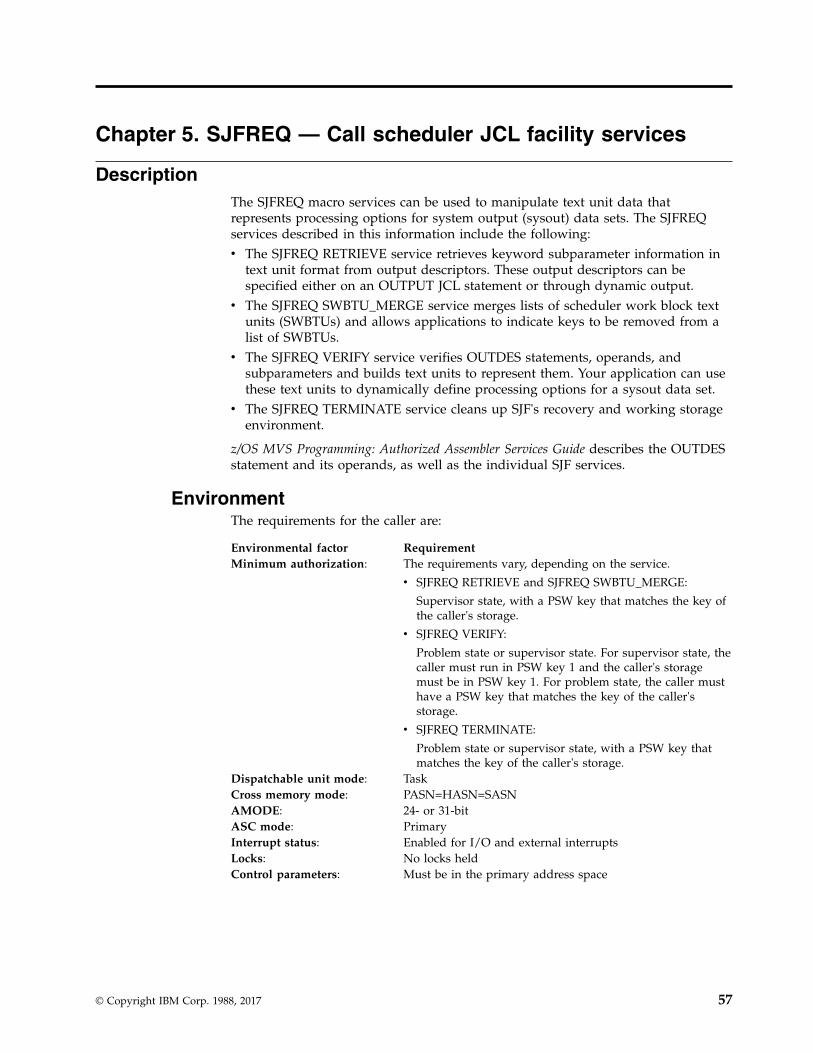
Chapter 5. SJFREQ — Call scheduler JCL facility services
DescriptionThe SJFREQ macro services can be used to manipulate text unit data thatrepresents processing options for system output (sysout) data sets. The SJFREQservices described in this information include the following:v The SJFREQ RETRIEVE service retrieves keyword subparameter information in
text unit format from output descriptors. These output descriptors can bespecified either on an OUTPUT JCL statement or through dynamic output.
v The SJFREQ SWBTU_MERGE service merges lists of scheduler work block textunits (SWBTUs) and allows applications to indicate keys to be removed from alist of SWBTUs.
v The SJFREQ VERIFY service verifies OUTDES statements, operands, andsubparameters and builds text units to represent them. Your application can usethese text units to dynamically define processing options for a sysout data set.
v The SJFREQ TERMINATE service cleans up SJF's recovery and working storageenvironment.
z/OS MVS Programming: Authorized Assembler Services Guide describes the OUTDESstatement and its operands, as well as the individual SJF services.
EnvironmentThe requirements for the caller are:
Environmental factor RequirementMinimum authorization: The requirements vary, depending on the service.
v SJFREQ RETRIEVE and SJFREQ SWBTU_MERGE:
Supervisor state, with a PSW key that matches the key ofthe caller's storage.
v SJFREQ VERIFY:
Problem state or supervisor state. For supervisor state, thecaller must run in PSW key 1 and the caller's storagemust be in PSW key 1. For problem state, the caller musthave a PSW key that matches the key of the caller'sstorage.
v SJFREQ TERMINATE:
Problem state or supervisor state, with a PSW key thatmatches the key of the caller's storage.
Dispatchable unit mode: TaskCross memory mode: PASN=HASN=SASNAMODE: 24- or 31-bitASC mode: PrimaryInterrupt status: Enabled for I/O and external interruptsLocks: No locks heldControl parameters: Must be in the primary address space
© Copyright IBM Corp. 1988, 2017 57

Programming requirementsThe application must include the CVT and IEFJESCT mapping macros. If theapplication codes the PARM parameter on the SJFREQ macro, the caller must alsodeclare a 4-byte pointer, SJFPTR.
For each SJFREQ invocation, the application must initialize certain fields in aninput parameter list. Fields are discussed within each service description. Thefollowing lists the parameter list name for each service.
Service Parameter List Name
RETRIEVE IEFSJREP
SWBTU_MERGE IEFSJSMP
VERIFY IEFSJVEP
TERMINATE Any of the three parameter list namesabove.
RestrictionsNone.
Input register informationBefore issuing the SJFREQ macro, the caller must ensure that the following generalpurpose registers (GPRs) contain the specified information:
RegisterContents
1 If PARM is not specified, the address of a word that contains the addressof the input parameter list
13 The address of an 18-word save area
Output register informationWhen control returns to the caller, the general purpose registers (GPRs) contain:
RegisterContents
0-1 Used as work registers by the system
2-13 Unchanged
14 Used as a work register by the system
15 Return code
When control returns to the caller, the ARs contain:
RegisterContents
0-1 Used as work registers by the system
2-13 Unchanged
14-15 Used as work registers by the system
SJFREQ macro
58 z/OS MVS Authorized Assembler Services Reference SET-WTO
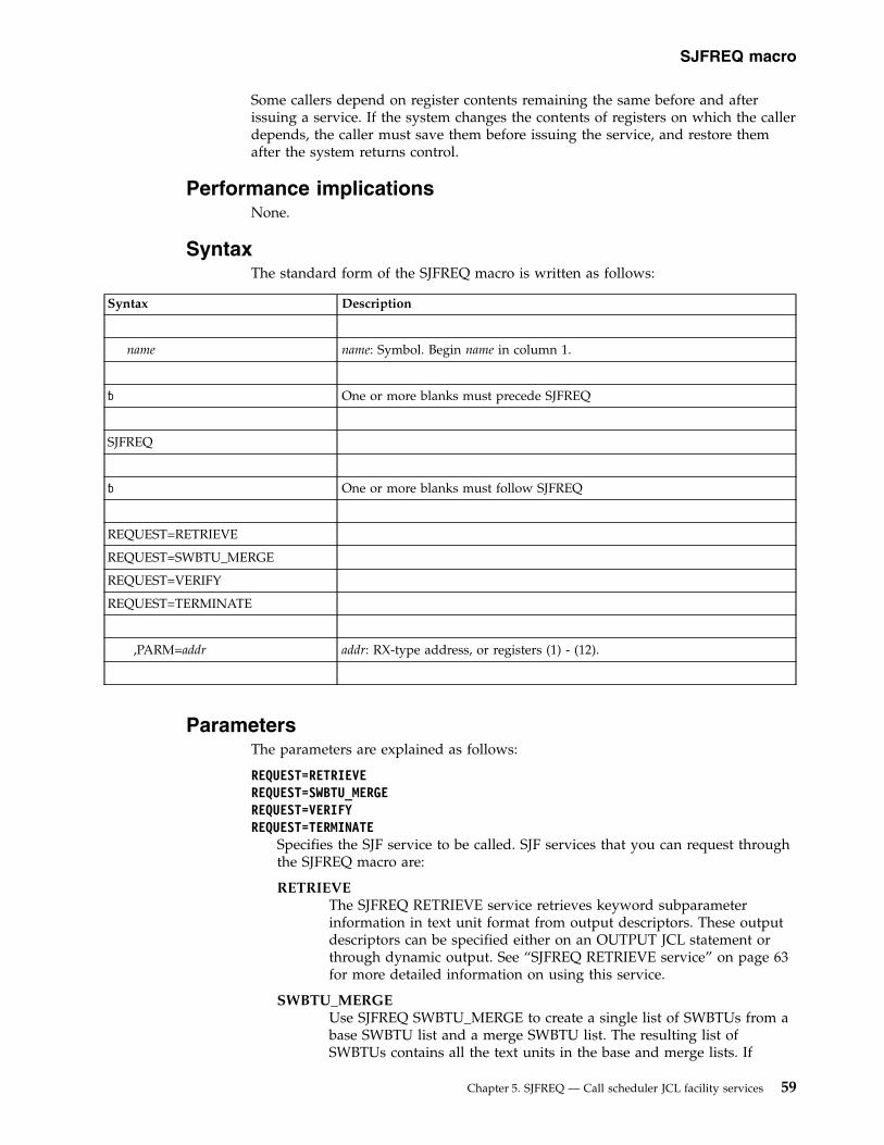
Some callers depend on register contents remaining the same before and afterissuing a service. If the system changes the contents of registers on which the callerdepends, the caller must save them before issuing the service, and restore themafter the system returns control.
Performance implicationsNone.
SyntaxThe standard form of the SJFREQ macro is written as follows:
Syntax Description
name name: Symbol. Begin name in column 1.
� One or more blanks must precede SJFREQ
SJFREQ
� One or more blanks must follow SJFREQ
REQUEST=RETRIEVE
REQUEST=SWBTU_MERGE
REQUEST=VERIFY
REQUEST=TERMINATE
,PARM=addr addr: RX-type address, or registers (1) - (12).
ParametersThe parameters are explained as follows:
REQUEST=RETRIEVEREQUEST=SWBTU_MERGEREQUEST=VERIFYREQUEST=TERMINATE
Specifies the SJF service to be called. SJF services that you can request throughthe SJFREQ macro are:
RETRIEVEThe SJFREQ RETRIEVE service retrieves keyword subparameterinformation in text unit format from output descriptors. These outputdescriptors can be specified either on an OUTPUT JCL statement orthrough dynamic output. See “SJFREQ RETRIEVE service” on page 63for more detailed information on using this service.
SWBTU_MERGEUse SJFREQ SWBTU_MERGE to create a single list of SWBTUs from abase SWBTU list and a merge SWBTU list. The resulting list ofSWBTUs contains all the text units in the base and merge lists. If
SJFREQ macro
Chapter 5. SJFREQ — Call scheduler JCL facility services 59

duplicate text units exist, only one appears in the final SWBTU list.The SWBTU_MERGE service also allows an application to indicatekeys to be removed from a list of SWBTUs. See “SJFREQSWBTU_MERGE service” on page 67 for more detailed information onusing this service.
VERIFYUse SJFREQ VERIFY to validate OUTDES statements and build textunits to be used as input to dynamic output. See “SJFREQ VERIFYservice” on page 76 for more detailed information on using thisservice.
TERMINATEUse SJFREQ TERMINATE after previously issuing a RETRIEVE,SWBTU_MERGE, or VERIFY request that specified the no cleanupoption (SJxxNOCU). TERMINATE cleans up SJF's recovery andworking storage environment. See “SJFREQ TERMINATE service” onpage 90 for more detailed information on using this service.
,PARM=addrSpecifies the address of the parameter list for the service requested. You mustinitialize certain parameter list fields for each service. The following listindicates where the parameter lists are described.v “SJFREQ RETRIEVE input parameters” on page 64 describes the RETRIEVE
parameter list.v “SJFREQ SWBTU_MERGE input parameters” on page 67 describes the
SWBTU_MERGE parameter list.v “SJFREQ VERIFY input parameters” on page 76 describes the VERIFY
parameter list.v You may only use IEFSJREP, IEFSJSMP, or IEFSJVEP (use the same one you
used on a prior request) for the TERMINATE service.
If you omit PARM, register 1 must contain the address of a word that containsthe address of the input parameter list.
ExampleInvoke the VERIFY service to:v Validate the syntax of the statement OUTDES, the keyword operand CHARS,
and the subparameter (GT10)v Build text units for the valid keyword operand and subparameter.
OUTDES out1 CHARS(GT10)
Use the label out1 for the OUTDES statement in this example. The statement is tobe converted into text units and used as input to OUTADD, the dynamic outputmacro.************************************************************************ This program segment has attributes that allow the defined ** storage to be altered. ************************************************************************* ** Set up SJVEP, VERIFY parameter list area. ** *************************************************************************
XC SJVEP(SJVELGTH),SJVEP Clear the parameter listMVC SJVEID,=A(SJVEPEYE) Parameter list IDMVI SJVEVERS,SJVECVER Parameter list versionOI SJVEFLAG,SJVENOCU Indicate no cleanup to SJF on this
SJFREQ macro
60 z/OS MVS Authorized Assembler Services Reference SET-WTO

* call, another call to SJF is* expected.
LA R4,SJVELGTH Get parameter list lengthSTH R4,SJVELEN Set parameter list length
** SJVESTOR and SJVEJDVT are properly* set at zero from XC instruction.************************************************************************* ** Set up statement and operand information. ** *************************************************************************
MVC SJVECMND,STATMNT Set statement name field to OUTDESST R2,SJVEOPEP Set the operand pointerLR R15,R3 Get pointer to last operand
* characterSR R15,R2 Get difference from first operand
* characterLA R15,1(R15) Add 1 to get proper operand lengthSTH R15,SJVEOPEL Set operand length
************************************************************************* ** Set up subparameter information. ** *************************************************************************
LA R15,1 Set up for first subparameterSTC R15,SJVEPARM Set subparameter number to 1ST R4,SJVEPRMP Set the subparameter pointerLR R15,R5 Get pointer to last subparameter
* characterSR R15,R4 Get difference from first
* subparameter characterLA R15,1(R15) Add 1 to get proper subparameter
* lengthSTH R15,SJVEPRML Set the subparameter pointer
************************************************************************* ** Set up output area information. ** *************************************************************************
LA R15,AREASIZE Get output work area lengthSTH R15,SJVETUBL Set text unit output area lengthLA R15,OUTAREA Get address of output work areaST R15,SJVETUBP Set text unit output area size
************************************************************************* ** Set up Register 1 to point to a word of storage that ** contains the address of SJVEP. ** *************************************************************************
LA R4,SJVEP Address ofST R4,SJVEPPTR the SJFREQ VERIFYLA R1,SJVEPPTR parameter list
************************************************************************* ** Invoke SJFREQ VERIFY service. ** ************************************************************************
SJFREQ macro
Chapter 5. SJFREQ — Call scheduler JCL facility services 61

*SJFREQ REQUEST=VERIFY Issue the SJF macro.
************************************************************************* ** Check for a zero return code. ** *************************************************************************
LTR R15,R15 Check service return codeBNZ SJFERR Go to nonzero return processing
*************************************************************************** ** In this portion of the example, a zero return and reason ** code are received. The output fields from the service ** contain the following information: ** ** Register 15 - contains zero. ** ** SJVEREAS - contains zero. ** ** SJVEOPD - this field contains the operand description ** for CHARS: ** "CHARACTER ARRANGEMENT TABLE" ** ** SJVEOPDL - this field contains the operand description ** length - decimal 27. ** ** SJVETUPL - this field contains an address into OUTAREA ** that is the start of the text unit pointer ** list. ** ** OUTAREA - this area contains the text unit pointer ** and the text unit that were built by VERIFY ** for the CHARS(GT10) specification. ************************************************************************** *SJFERR DS 0H Label used for branch when SJFREQ* VERIFY returns with a nonzero* return code.** Code to handle SJFREQ errors************************************************************************* ** Storage definitions ** *************************************************************************
IEFSJVEP DSECT=NO SJFREQ VERIFY parameter list area*SJVEPPTR DS A Field used to contain SJVEP address**OUTAREA DS XL1024 Area used by SJFREQ VERIFY to build* text units for valid operands and* subparameters.*AREASIZE EQU *-OUTAREA Size of AREA************************************************************************* ** Equates and Constants *
SJFREQ macro
62 z/OS MVS Authorized Assembler Services Reference SET-WTO

* *************************************************************************R0 EQU 0 Register 0R1 EQU 1 Register 1R2 EQU 2 Register 2R3 EQU 3 Register 3R4 EQU 4 Register 4R5 EQU 5 Register 5R6 EQU 6 Register 6R7 EQU 7 Register 7R8 EQU 8 Register 8R9 EQU 9 Register 9R15 EQU 15 Register 15*SJVEPEYE EQU C’SJVE’ VERIFY parameter list identifierSTATMNT DC CL8’OUTDES ’ Statement name************************************************************************
SJFREQ RETRIEVE serviceThe SJFREQ RETRIEVE service retrieves keyword subparameter information in textunit format from output descriptors. These output descriptors can be specifiedeither on an OUTPUT JCL statement or through dynamic output. Your applicationcan invoke this service to retrieve output descriptor information in a functionalsubsystem environment.
Programming requirementsAn application must complete the following steps to issue a RETRIEVE request:1. Obtain storage for the RETRIEVE parameter list (IEFSJREP) and initialize the
fields. Place the address of IEFSJREP in the PARM parameter.2. Provide a keyword list (SJRELIST). The keyword list contains the keywords for
which the application wants information retrieved. “SJFREQ RETRIEVEkeyword list” describes the list.
3. Issue SJFREQ RETRIEVE.
SJFREQ RETRIEVE keyword listThe keyword list contains paired fields; each pair consists of a keyword field and apointer field. In the list, the application specifies the JCL keywords for whichinformation is to be retrieved. For each keyword specified, the RETRIEVE servicereturns in SJRETPAD a pointer to the text unit pointer list associated with thekeyword.
The following table shows the SJRELIST paired fields and their offsets and lengths.The fields that the application initializes are indicated.
Field Name Offset (bytes) ValueLength(bytes)
Value to be assigned
SJRELIST
SJREKEYW 0 (X'0') 8 keyword 1 (initialized by application)
SJRETPAD 8 (X'8') 4 pointer (returned by the system)
SJREKEYW 12 (X'C') 8 keyword 2 (initialized by application)
SJRETPAD 20 (X'14') 4 pointer (returned by the system)
SJFREQ macro
Chapter 5. SJFREQ — Call scheduler JCL facility services 63

Field Name Offset (bytes) ValueLength(bytes)
Value to be assigned
. . . .
. . . .
In addition to JCL keywords, SJFREQ can also return a text unit for the keywordproviding special TCP/IP support. This text unit has the following characteristicsin the Output Descriptor.
Characteristic:Keyword Parameter: IPADDRKey in Hex: 8005Maximum number of ValueFields: 1Length of Value Field: 0 - 124Value Field: EBCDIC text '40'X - 'FE'XFunction: IP address extracted from the DEST='IP:ip-address' format of
the DEST=keyword
SJFREQ RETRIEVE input parametersIn addition to providing a keyword list, for each SJFREQ invocation, you need toinitialize certain fields of parameter list IEFSJREP. The list of parameters anddescriptions of their values are below.
SJREIDThe identifier ‘SJRE’ of the RETRIEVE parameter list. Assign the symbolicequate SJRECID to this field.
SJREVERSThe current version number of the RETRIEVE parameter list. Assign thesymbolic equate SJRECVER to this field.
SJREFLAGThe environment control flag.
SJRENOCUIndicates whether the SJF environment is preserved from call tocall or obtained for each call. Set to one to preserve theenvironment from call to call. Set to zero to obtain a newenvironment for a call.
SJRELENThe length of the RETRIEVE parameter list (IEFSJREP). Assign thesymbolic equate SJRELGTH to this field.
SJRESTORThe local working storage pointer or zero. This field must contain zero onthe first RETRIEVE call. On subsequent calls, the field contains the valuereturned from the most recent RETRIEVE call. Use the returned value forsubsequent calls.
SJREJDVTEnter zero for this field on input. This field must contain zero on the firstRETRIEVE call. On subsequent calls, the field contains the value returnedfrom the most recent RETRIEVE call. Use the returned value forsubsequent calls.
SJFREQ macro
64 z/OS MVS Authorized Assembler Services Reference SET-WTO

SJRETOKNEnter the output descriptor token in this field. If you are coding a PrintService Facility (PSF) exit, refer to PSF/MVS System Programming Guide forinformation on obtaining the output descriptor token. The token can beobtained from the GDSOUTK field in data area IAZFSIP.
SJREAREAThe address of the storage area in which RETRIEVE is to return thekeyword subparameter information in text unit format from outputdescriptors.
SJRESIZEThe amount of the storage allocated for the output descriptor information.
SJRENKWDThe number of keywords passed in the keyword list (SJRELIST).
SJREKWDLThe address of the keyword list (SJRELIST).
SJFREQ RETRIEVE output parametersIn addition to the output provided in the keyword list, the RETRIEVE servicereturns data in several fields of the IEFSJREP parameter list. The list of outputparameters and their descriptions are below.
SJREREASContains a reason code returned from the RETRIEVE service. This fieldcontains a value when register 15 contains a return code other than zero.
SJREKERRContains the address of the first keyword in the keyword list that causedthe error.
SJRETPADContains the address of the list of text unit pointers. Each text unit pointerpoints to a returned text unit. The last text unit has the high-order bit setto one.
ABEND codesNone.
SJFREQ RETRIEVE return and reason codesSJFREQ RETRIEVE return codes appear in register 15. When SJFREQ returnscontrol to your program, SJREREAS contains a reason code when register 15contains a nonzero value. Return and reason codes are defined in macro IEFSJRC.The following table identifies the hexadecimal return and reason codecombinations, tells what each means, and recommends an action you should take.
Table 7. Return and Reason Codes for the SJFREQ RETRIEVE Service
Return Code Reason Code Meaning and Action
0 000 Meaning: RETRIEVE processing completedsuccessfully.
Action: None.
4 002 Meaning: Program error. The token specified inSJRETOKN is not valid.
Action: Specify a valid token in SJRETOKN.
SJFREQ macro
Chapter 5. SJFREQ — Call scheduler JCL facility services 65

Table 7. Return and Reason Codes for the SJFREQ RETRIEVE Service (continued)
Return Code Reason Code Meaning and Action
4 004 Meaning: Program error. The RETRIEVE requestwas not processed. The value specified inSJREJDVT is not valid.
Action: Set SJREJDVT to hexadecimal zeros or tothe value returned on the previous call.
4 005 Meaning: System error. The informationreferenced by parameter field SJREJDVT does notexist.
Action: SJF did not initialize properly. Contactthe appropriate IBM support personnel.
4 0C8 Meaning: Program error. SJRETOKN refers to aJCL statement that is not valid.
Action: Supply a value in SJRETOKN that refersto a valid JCL statement.
4 0C9 Meaning: Program error. A keyword in thekeyword list is not defined to the JCL statementreferred to by SJRETOKN.
Action: SJREKERR contains the address of thekeyword in error. Correct or delete the keywordin error.
4 258 Meaning: Program error. The area specified bySJRESIZE is less than the minimum allowed.
Action: Define SJRESIZE to a size that cancontain at least one text unit.
4 25B Meaning: Program error. No storage area addresswas specified.
Action: Specify a storage area address inSJREAREA.
4 25C Meaning: Program error. The value inSJRENKWD indicates that no keywords werespecified.
Action: Specify a value of one or greater forSJRENKWD.
4 25D Meaning: Program error. No keyword listaddress was specified.
Action: Specify a keyword list address inSJREKWDL.
4 25F Meaning: Program error. Zero is given as thevalue for a keyword in the keyword list.
Action: SJREKERR contains the address of thekeyword. Change the zero to a valid value.
0C 000 Meaning: System error. The system could notobtain storage for this request.
Action: Inform your system programmer of thisproblem.
10 000 Meaning: System error. The ESTAE-type recoveryroutine failed.
Action: Inform your system programmer of thisproblem.
SJFREQ macro
66 z/OS MVS Authorized Assembler Services Reference SET-WTO

Table 7. Return and Reason Codes for the SJFREQ RETRIEVE Service (continued)
Return Code Reason Code Meaning and Action
14 000 Meaning: System error. SJF encountered acondition that caused an abnormal termination.
Action: Check the input parameters, particularlyany pointer fields, to determine if the inputvalues are correct.
18 000 Meaning: System error. The service routines forSJFREQ are not available.
Action: SJF did not initialize properly. Contactthe appropriate IBM support personnel.
SJFREQ SWBTU_MERGE serviceUse the SWBTU_MERGE service to merge a list of base SWBTUs with a list ofmerge SWBTUs that contain modifications. An application can also use theSWBTU_MERGE service to indicate keys to be removed from a list of SWBTUs.
Programming requirementsYou must provide input information in the SWBTU_MERGE parameter list(IEFSJSMP).
In addition to the IEFSJSMP parameter list, you can provide an erase list. An eraselist is a contiguous set of text units that you request to be erased from a baseSWBTU. An erase list is required when you set SJSMETUP and SJSMETUS. If onlya merge SWBTU and erase list are provided on input, SWBTU_MERGE validatesthe erase list, but does not apply it to the resulting SWBTU.
SJFREQ SWBTU_MERGE input parametersFor each SJFREQ invocation, you need to initialize certain fields of parameter listIEFSJSMP. The list of parameters and descriptions of their values are below.
SJSMIDThe identifier ‘SJSM’ of the SWBTU_MERGE parameter list. Assign thesymbolic equate SJSMCID to this field.
SJSMVERSThe current version number of the SWBTU_MERGE parameter list. Assignthe symbolic equate SJSMCVER to this field.
SJSMFLAGThe environment control flag.
SJSMNOCUIndicates whether the SJF environment is preserved from call tocall or obtained for each call. Set to one to preserve theenvironment from call to call. Set to zero to obtain a newenvironment for a call.
SJSMLENThe length of the SWBTU_MERGE parameter list (IEFSJSMP). Assign thesymbolic equate SJSMLGTH to this field.
SJSMSTORThe local working storage pointer or zero. This field must contain zero on
SJFREQ macro
Chapter 5. SJFREQ — Call scheduler JCL facility services 67

the first SWBTU_MERGE call. On subsequent calls, the field contains thevalue returned from the most recent SWBTU_MERGE call. Use the valuereturned for subsequent calls.
SJSMAREAThe address of the area to which a single SWBTU is returned afterSWBTU_MERGE processing. SJSMSIZE contains the size of this area.
SJSMSIZEThe length of the area to which a single SWBTU is returned afterSWBTU_MERGE processing. Specify the size of SJSMAREA in this field.
SJSMSWBNThe number of SWBTU pointers in the base SWBTU pointer list. This fieldcan be zero if the address of the base SWBTU pointer list (SJSMSWBA) isalso zero and you specify a merge SWBTU pointer list.
SJSMSWBAThe address of the base SWBTU pointer list. You can specify zero for thisvalue if the number of SWBTU pointers in the base SWBTU pointer list(SJSMSWBN) is zero and you specify a merge SWBTU pointer list.
SJSMMTUPThe address of the merge SWBTU pointer list. You can specify zero for thisvalue if the number of SWBTU pointers in the merge SWBTU pointer list(SJSMMTUN) is zero and you specify a base SWBTU pointer list.
SJSMMTUNThe number of SWBTU pointers in the merge SWBTU pointer list. You canspecify zero for this value if the address of the merge SWBTU pointer list(SJSMMTUP) is zero and you specify a base SWBTU pointer list.
SJSMETUSThe number of elements contained on input in the erase text unit list area.You can specify zero for this value if the address of the erase text unit listarea (SJSMETUP) is zero.
SJSMETUPThe address of the erase text unit list area. You can specify zero for thisvalue if the address of the erase text unit list area (SJSMETUS) is zero.
SJSMJDVTEnter zero for this field on input. This field must contain zero on the firstSWBTU_MERGE call. On subsequent calls, the field contains the valuereturned from the most recent SWBTU_MERGE call. Use the valuereturned for subsequent calls.
SJSMWARNSet on to indicate that processing should continue after allowable errors.Clear this field so that processing does not continue after allowable errors.Allowable errors are described “Merging SWBTUs” in z/OS MVSProgramming: Authorized Assembler Services Guide.
SJSMBYMVSet on to indicate whether the merge SWBTU text units should bevalidated.
SJSMBYEVSet on to indicate whether the erase text units' keys should be validated.
SJSMSBTLWhen SJSMSWBA and SJSMSWBN contain values, this field must contain
SJFREQ macro
68 z/OS MVS Authorized Assembler Services Reference SET-WTO
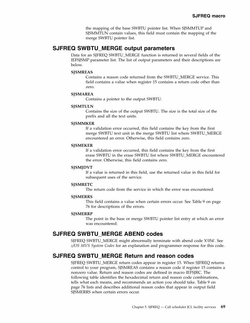
the mapping of the base SWBTU pointer list. When SJSMMTUP andSJSMMTUN contain values, this field must contain the mapping of themerge SWBTU pointer list.
SJFREQ SWBTU_MERGE output parametersData for an SJFREQ SWBTU_MERGE function is returned in several fields of theIEFSJSMP parameter list. The list of output parameters and their descriptions arebelow.
SJSMREASContains a reason code returned from the SWBTU_MERGE service. Thisfield contains a value when register 15 contains a return code other thanzero.
SJSMAREAContains a pointer to the output SWBTU.
SJSMTULNContains the size of the output SWBTU. The size is the total size of theprefix and all the text units.
SJSMMKERIf a validation error occurred, this field contains the key from the firstmerge SWBTU text unit in the merge SWBTU list where SWBTU_MERGEencountered an error. Otherwise, this field contains zero.
SJSMEKERIf a validation error occurred, this field contains the key from the firsterase SWBTU in the erase SWBTU list where SWBTU_MERGE encounteredthe error. Otherwise, this field contains zero.
SJSMJDVTIf a value is returned in this field, use the returned value in this field forsubsequent uses of the service.
SJSMRETCThe return code from the service in which the error was encountered.
SJSMERRSThis field contains a value when certain errors occur. See Table 9 on page76 for descriptions of the errors.
SJSMERRPThe point in the base or merge SWBTU pointer list entry at which an errorwas encountered.
SJFREQ SWBTU_MERGE ABEND codesSJFREQ SWBTU_MERGE might abnormally terminate with abend code X'054'. Seez/OS MVS System Codes for an explanation and programmer response for this code.
SJFREQ SWBTU_MERGE Return and reason codesSJFREQ SWBTU_MERGE return codes appear in register 15. When SJFREQ returnscontrol to your program, SJSMREAS contains a reason code if register 15 contains anonzero value. Return and reason codes are defined in macro IEFSJRC. Thefollowing table identifies the hexadecimal return and reason code combinations,tells what each means, and recommends an action you should take. Table 9 onpage 76 lists and describes additional reason codes that appear in output fieldSJSMERRS when certain errors occur.
SJFREQ macro
Chapter 5. SJFREQ — Call scheduler JCL facility services 69

Table 8. Return and Reason Codes for the SJSMREAS Macro
Return Code Reason Code Meaning and Action
0 000 Meaning: SWBTU_MERGE processing completedsuccessfully.
Action: None.
0 0CA Meaning: Program error. SWBTU_MERGEprocessing completed successfully; however, thevalue in SJSMMKER or SJSMEKER was ignored.SJSMMKER or SJSMEKER contains a key in error.
Action: Determine if it is acceptable for theinformation in SJSMMKER or SJSMEKER to beignored.
0 0CB Meaning: Program error. SWBTU_MERGEprocessing completed successfully; however, thetext unit count for the key that appears inSJSMMKER is not valid. All data for this text unitis ignored.
Action: Determine if it is acceptable for the textunit data to be ignored.
0 1F4 Meaning: Program error. SWBTU_MERGEprocessing completed successfully; however, atext unit length in a length-value pair for the keythat appears in SJSMMKER is not valid. All datafor this text unit is ignored.
Action: Check the length specified for the keythat appears in SJSMMKER. Determine if it isacceptable for the text unit to be ignored.
0 1F5 Meaning: Program error. SWBTU_MERGEprocessing completed successfully; however, atext unit value in a length-value pair for the keythat appears in SJSMMKER is not valid. All datafor this text unit is ignored.
Action: Check the value specified for the key thatappears in SJSMMKER. Determine if it isacceptable for the text unit to be ignored.
0 1F6 Meaning: Program error. SWBTU_MERGEprocessing completed successfully; however, anumeric value of a length-value pair in a textunit exceeds the maximum allowable value.SJSMMKER contains the key from the text unitthat is in error. All data for this text unit isignored.
Action: Check the value specified in the text unitand determine if it is acceptable for the text unitto be ignored.
0 1F7 Meaning: Program error. SWBTU_MERGEprocessing completed successfully; however, anumeric value of a length-value pair in a textunit is less than the minimum allowable value.SJSMMKER contains the key from the text unitthat is in error. All data for this text unit isignored.
Action: Check the value specified in the text unitand determine if it is acceptable for the text unitto be ignored.
SJFREQ macro
70 z/OS MVS Authorized Assembler Services Reference SET-WTO

Table 8. Return and Reason Codes for the SJSMREAS Macro (continued)
Return Code Reason Code Meaning and Action
0 1FE Meaning: Program error. SWBTU_MERGEprocessing completed successfully; however, acharacter value level length in a text unit exceedsthe maximum allowed for character data.SJSMMKER contains the key from the text unitthat is in error. All data for this text unit isignored.
Action: Check the value specified in the text unitand determine if it is acceptable for the text unitto be ignored.
0 1FF Meaning: Program error. SWBTU_MERGEprocessing completed successfully; however, thenumber of levels for a character value in a textunit exceeds the maximum allowed. SJSMMKERcontains the key from the text unit that is inerror. All data for this text unit is ignored.
Action: Check the value specified in the text unitand determine if it is acceptable for the text unitto be ignored.
0 200 Meaning: Program error. SWBTU_MERGEprocessing completed successfully; however, thefirst character of the level in the character valuein a text unit is not valid for character data.SJSMMKER contains the key from the text unitthat is in error. All data for this text unit isignored.
Action: Check the value specified in the text unitand determine if it is acceptable for the text unitto be ignored.
0 201 Meaning: Program error. SWBTU_MERGEprocessing completed successfully; however, acharacter is not valid for character data. Theincorrect value is not the first character of thelevel in the character value in a text unit.SJSMMKER contains the key from the text unitthat is in error. All data for this text unit isignored.
Action: Check the value specified in the text unitand determine if it is acceptable for the text unitto be ignored.
0 226 Meaning: Program error. SWBTU_MERGEprocessing completed successfully; however, atext unit contained a text character that is outsidethe range X'40' - X'FE'. SJSMMKER contains thekey from the text unit that is in error. All data forthis text unit is ignored.
Action: Check the value specified in the text unitand determine if it is acceptable for the text unitto be ignored.
0 227 Meaning: SWBTU_MERGE processing completedsuccessfully; however, the sequence of charactersin a text unit is not valid. SJSMMKER containsthe key from the text unit that is in error. All datafor this text unit is ignored.
Action: Check the value specified in the text unitparameter and determine if it is acceptable forthe text unit to be ignored.
SJFREQ macro
Chapter 5. SJFREQ — Call scheduler JCL facility services 71

Table 8. Return and Reason Codes for the SJSMREAS Macro (continued)
Return Code Reason Code Meaning and Action
0 228 Meaning: SWBTU_MERGE processing completedsuccessfully; however, there are bits on in the textunit parameter that the system does notrecognize. SJSMMKER contains the key from thetext unit that is in error. All data for this text unitis ignored.
Action: Check the value specified in the text unitparameter and determine if it is acceptable forthe text unit to be ignored.
0 76C Meaning: SWBTU_MERGE processing completedsuccessfully. The resulting SWBTU (pointed to bySJSMAREA) has a prefix and no text units.
Action: None required. However, you might takesome action based on your application.
4 0C8 Meaning: Program error. The specified verb isnot defined to the system.
Action: Specify a valid verb.
4 0CA Meaning: Program error. The system does notrecognize the text unit key. SJSMMKER orSJSMEKER contains the key from the text unitthat is in error. All data for this text unit isignored.
Action: Check the text unit key. Correct the keyand issue the SJFREQ macro again.
4 0CB Meaning: Program error. The count in a text unitis not valid. SJSMMKER contains the key for thetext unit that is not valid.
Action: Check the text unit count. Correct thecount and issue the SJFREQ macro again.
4 1F4 Meaning: Program error. A length in alength-value pair in a text unit is not valid.SJSMMKER contains the key for the text unit thatis not valid.
Action: Check the length. Correct the length andissue the SJFREQ macro again.
4 1F5 Meaning: Program error. A text unit value in alength-value pair is not valid. SJSMMKERcontains the key for the text unit that is not valid.
Action: Check the value. Correct the value andissue the SJFREQ macro again.
4 1F6 Meaning: Program error. A numeric value of alength-value pair in a text unit exceeds themaximum allowable value. SJSMMKER containsthe key from the text unit that is in error.
Action: Check the value. Correct the value andissue the SJFREQ macro again.
4 1F7 Meaning: Program error. A numeric value of alength-value pair in a text unit is less than theminimum allowable value. SJSMMKER containsthe key from the text unit that is in error.
Action: Check the value. Correct the value andissue the SJFREQ macro again.
SJFREQ macro
72 z/OS MVS Authorized Assembler Services Reference SET-WTO

Table 8. Return and Reason Codes for the SJSMREAS Macro (continued)
Return Code Reason Code Meaning and Action
4 1FE Meaning: Program error. A character value levellength in a text unit exceeds the maximumallowed for character data. SJSMMKER containsthe key from the text unit that is in error.
Action: Check the value specified in the text unit.Correct the value and issue the SJFREQ macroagain.
4 1FF Meaning: Program error. The number of levelsfor a character value in a text unit exceeds themaximum allowed. SJSMMKER contains the keyfrom the text unit that is in error.
Action: Check the value specified in the text unit.Correct the value and issue the SJFREQ macroagain.
4 200 Meaning: Program error. A character in a textunit is not valid for character data. The characteris the first character in the level in the text unit.SJSMMKER contains the key from the text unitthat is in error.
Action: Check the value specified in the text unit.Correct the value and issue the SJFREQ macroagain.
4 201 Meaning: Program error. A character is not validfor character data. The character is not the firstcharacter of the level in the character value in atext unit. SJSMMKER contains the key from thetext unit that is in error.
Action: Check the value specified in the text unit.Correct the value and issue the SJFREQ macroagain.
4 206 Meaning: A text unit key contained hex zeros.
Action: Check the text unit key value specified inthe text unit. Correct the value and issue theSJFREQ macro again.
4 226 Meaning: Program error. A text unit contained atext character that is outside the range X'40' -X'FE'. SJSMMKER contains the key from the textunit that is in error.
Action: Check the value specified in the text unit.Correct the value and issue the SJFREQ macroagain.
4 227 Meaning: The sequence of characters in a textunit is not valid. SJSMMKER contains the keyfrom the text unit that is in error.
Action: Check the value specified in the text unitparameter. Correct the value and issue theSJFREQ macro again.
4 228 Meaning: There are bits on in the parameter thatthe system does not recognize. SJSMMKERcontains the key from the text unit that is inerror.
Action: Check the value specified in the text unitparameter. Correct the value and issue theSJFREQ macro again.
SJFREQ macro
Chapter 5. SJFREQ — Call scheduler JCL facility services 73

Table 8. Return and Reason Codes for the SJSMREAS Macro (continued)
Return Code Reason Code Meaning and Action
4 76D Meaning: Program error. The output area(identified by SJSMAREA and SJSMSIZE) is notlarge enough for the resulting SWBTU.
Action: Increase the size of the output area andissue the SJFREQ macro again.
4 76E Meaning: Program error. One of the followingoccurred:
v The base SWBTU pointer list address(SJSMSWBA) is zero and the number ofSWBTU pointers (SJSMSWBN) in the basepointer list is not zero
v The SWBTU pointer list address is not zeroand the number of SWBTU pointers in thebase pointer list is zero.
Action: Supply the correct values for SJSMSWBAand SJSMSWBN and issue the SJFREQ macroagain.
4 76F Meaning: Program error. One of the followingoccurred:
v The merge SWBTU pointer list address(SJSMMTUP) is zero and the number ofSWBTU pointers (SJSMMTUN) in the mergepointer list is not zero
v The merge SWBTU pointer list address is notzero and the number of SWBTU pointers in themerge pointer list is zero.
Action: Supply the correct values for SJSMMTUPand SJSMMTUN and issue the SJFREQ macroagain.
4 770 Meaning: Program error. One of the followingoccurred:
v The erase text unit address (SJSMETUP) is zeroand the size of the erase text unit list area(SJSMETUS) is not zero
v The erase text unit address (SJSMETUP) is notzero and the size of the erase text unit list area(SJSMETUS) is zero.
Action: Supply the correct values for SJSMETUPand SJSMETUS and issue the SJFREQ macroagain.
4 771 Meaning: Program error. Either the output areaaddress (SJSMAREA) is zero or the output areasize (SJSMSIZE) is not greater than zero.
Action: Check the values in SJSMAREA andSJSMSIZE and determine which is incorrect.Specify valid values and issue the SJFREQ macroagain.
SJFREQ macro
74 z/OS MVS Authorized Assembler Services Reference SET-WTO

Table 8. Return and Reason Codes for the SJSMREAS Macro (continued)
Return Code Reason Code Meaning and Action
4 772 Meaning: Program error. One of the followinghappened:
v Neither a base SWBTU nor a modify SWBTUwere specified (SJSMSWBA and SJSMMTUPare both zero).
v A base SWBTU was provided, but no modifySWBTU and no erase list were provided(SJSMMTUP and SJSMETUP are zero).
Action: Do one of the following:
v Specify a base or modify SWBTU.
v If a base SWBTU was provided, specify eithera modify SWBTU or an erase list.
4 773 Meaning: Program error. The verb name in themerge SWBTU list does not match the verb namein the base SWBTU list.
Action: Supply input for the same verb in boththe base SWBTU list and the merge SWBTU list.
4 774 Meaning: Program error. One of the followingoccurred:
v The version number (SJSMVERS) supplied inthe parameter list does not match the versiondefined in macro IEFSJSMP
v The length (SJSMLEN) supplied in theparameter list does not match the actuallength.
Action: Ensure that the constant SJSMCVER isused in field SJSMVERS of the input parameterlist and that the constant SJSMLGTH is used infield SJSMLEN of the input parameter list.
4 7A1 Meaning: Program error. The base SWBTU listcontains an error.
Action: Check output fields SJSMERRP andSJSMERRS. SJSMERRP contains the address of aSWBTU that is in error. SJSMERRS may contain areason code that indicates an error in the base ormerge SWBTU list. See Table 9 on page 76 for thereason code descriptions.
0C 000 Meaning: System error. The system could notobtain storage for this request.
Action: Inform your system programmer of thisproblem.
10 000 Meaning: System error. The ESTAE-type recoveryroutine failed.
Action: Inform your system programmer of thisproblem.
14 000 Meaning: System error. SJF encountered acondition that caused an abnormal termination.
Action: Check the input parameters, particularlyany pointer fields, to determine if the inputvalues are correct.
SJFREQ macro
Chapter 5. SJFREQ — Call scheduler JCL facility services 75

Table 8. Return and Reason Codes for the SJSMREAS Macro (continued)
Return Code Reason Code Meaning and Action
18 000 Meaning: System error. The service routines forSJFREQ are not available.
Action: SJF did not initialize properly. Contactthe appropriate IBM support personnel.
Output field SJSMERRS contains a reason code when certain errors occur. Table 9lists the reason codes and their meanings.
Table 9. Return and Reason Codes for the SJFREQ Macro SWBTU_MERGE Service
Return Code Reason Code Meaning and Action
4 018 Meaning: Program error. The application did notsupply either the base SWBTU list or the mergeSWBTU list.
Action: Determine which list is missing. Supplythe missing list and issue the SJFREQ macroagain.
4 019 Meaning: Program error. The prefix for either thebase SWBTU list or merge SWBTU list is notvalid.
Action: Determine which prefix is not valid.Supply the correct prefix and issue the SJFREQmacro again.
4 028 Meaning: Program error. The verb and labelvalues in either the base SWBTU list or themerge SWBTU list do not match.
Action: Determine which pair does not match.Correct the information and issue the SJFREQmacro again.
SJFREQ VERIFY serviceUse VERIFY to validate and build text units to represent an OUTDES statement, itsoperands, subparameters and sublist elements. The OUTDES informationcorresponds to SJF-defined information on the OUTPUT JCL statement. If you donot specify correctly the input subparameter data, VERIFY returns an errormessage.
SJFREQ VERIFY input parametersFor each SJFREQ invocation, you need to initialize certain fields of parameter listIEFSJVEP. See SJVEP in z/OS MVS Data Areas in the z/OS Internet library(www.ibm.com/systems/z/os/zos/library/bkserv) for the mapping provided bythe IEFSJVEP mapping macro. The list of parameters and descriptions of theirvalues are below, followed by Table 10 on page 78 that summarizes the requiredparameter fields for the three SJFREQ VERIFY functions.
VERIFY performs three functions. Use Table 10 on page 78 to determine therequired parameters for the SJFREQ VERIFY function you want to request. Thetable gives details about the required values.
SJVEIDThe identifier ‘SJVE’ of the VERIFY parameter list. Assign the symbolicequate SJVECID to this field.
SJFREQ macro
76 z/OS MVS Authorized Assembler Services Reference SET-WTO

SJVEVERSThe current version number of the SJFREQ VERIFY parameter list. Assignthe symbolic equate SJVECVER to this field.
SJVEFLAGThe environment control flag.
SJVENOCUIndicates whether the SJF environment is preserved from call tocall or obtained for each call. Parameter SJVESTOR references theenvironment. When set to 0, the environment is obtained for eachcall. When set to 1, the environment is preserved.
SJVEUNAUIndicates whether the caller is unauthorized. If an applicationmakes repetitive service calls using the same SJF environment, theauthorization must be same for each call.
SJVELENThe length of the VERIFY parameter list (IEFSJVEP). Assign the symbolicequate SJVELGTH to this field.
SJVESTORThe local working storage pointer or zero. This field must contain zero onthe first VERIFY call. On subsequent calls, the field contains the valuereturned from the most recent VERIFY call.
SJVEJDVTEnter zero for this field on input. If a value is returned in the field, use thereturned value for subsequent uses of the service.
SJVECMNDThe name of the statement that contains the output descriptor information.Specify the statement name OUTDES in an 8-character field, left-justified,and padded with blanks.
SJVEOPEPThe pointer to the operand or keyword operand to be validated. This fieldshould contain an address of the first byte of the operand or keywordoperand. Set the length of the operand in SJVEOPEL. Zero is a valid valuewhen specifying just the statement name as specified in SJVECMND.
SJVEOPELThe length of the operand or keyword operand to be validated. This fieldshould contain the actual length of the operand or keyword operandpointed to by SJVEOPEP.
SJVEPARMThe subparameter number representing the subparameter to be validated.Set this value to one whenever validating an operand. When validating akeyword operand, set this to the correct subparameter number.
SJVESUBLThe sublist element number representing the sublist element to bevalidated. This field should be set to zero if the subparameter is not asublist.
SJVEPRMPThe pointer to the subparameter or sublist element to be validated. Set thelength of the subparameter or sublist element in SJVEPRML.
SJFREQ macro
Chapter 5. SJFREQ — Call scheduler JCL facility services 77

SJVEPRMLThe length of the subparameter or sublist element pointed to bySJVEPRMP. This field should contain the actual length of the subparameteror sublist element pointed to by SJVEPRMP.
SJVETUBLThe length of the text unit output area. The field should contain the lengthof the output area pointed to by SJVETUBP. The minimum you shouldspecify for the output area is 256 bytes plus sufficient storage toaccommodate the text units that will be built as a result of your VERIFYrequest. A work area of 1K is large enough for any set of text units to bebuilt.
SJVETUBPThe pointer to the text unit output area. The output area will contain thetext unit pointer list and text units upon return from the VERIFY servicecall. If the output area is not large enough to hold all the text units and thetext unit pointer list, you can point to and use an additional output area.When using additional output areas, the original output area must beaccessible to SJF; it cannot be freed or changed. Set the length of the outputarea in SJVETUBL.
SJVEFLG1The VERIFY option flag.
SJVELSTCIndicates last call for the text units being built. Set this indicator toone for the last VERIFY call. Setting this indicator on makes thetext units available for use.
SJVERSBSIndicates that the same text unit output area is to be used formultiple calls. SJVETUBS contains the returned length of the areathe service used to build the text units and text unit pointer list.When this indicator is on, SJVETUBP must be the same for eachVERIFY call.
SJVEQUOTIndicates that a subparameter was specified in quotation marks. Toallow quotation marks on all subparameters, the caller can set thisbit to zero. Note that some subparameters do not allow quotationmarks. For any value specified in quotation marks, the callershould have:v Removed the delimiting quotation marksv Converted two consecutive single quotation marks to one single
quotation mark.
SJVEPRFXThe prefix to be concatenated to a subparameter that is a data set name.This field is not used if SJVEQUOT is on or if the subparameter is notdefined as allowing unqualified data set names. If no prefix is specified,this field must be set to zero.
Table 10. Required Fields for SJFREQ VERIFY Functions
IEFSJVEPparameter listfield
Validate a subparameter or sublistelement and build a text unit
Validate an operand or keywordoperand
Validate astatement name
SJVEID Symbolic equate SJVECID Symbolic equate SJVECID Symbolic equateSJVECID
SJFREQ macro
78 z/OS MVS Authorized Assembler Services Reference SET-WTO

Table 10. Required Fields for SJFREQ VERIFY Functions (continued)
IEFSJVEPparameter listfield
Validate a subparameter or sublistelement and build a text unit
Validate an operand or keywordoperand
Validate astatement name
SJVEVERS Symbolic equate SJVECVER Symbolic equate SJVECVER Symbolic equateSJVECVER
SJVENOCU Set to indicate if the SJF environmentshould be reused.
Set to indicate if the SJF environmentshould be reused.
Set to indicate ifthe SJFenvironmentshould be reused.
SJVEUNAU Set to indicate if the caller isauthorized.
Set to indicate if the caller isauthorized.
Set to indicate ifthe caller isauthorized.
SJVELEN Symbolic equate SJVELGTH Symbolic equate SJVELGTH Symbolic equateSJVELGTH
SJVESTOR Local working storage pointer orzero
Local working storage pointer orzero
Local workingstorage pointer orzero
SJVECMND Statement name associated with theoperand for which the subparameteror sublist is to be validated.
Statement name associated with theoperand to be validated.
Statement name tobe validated.
SJVEOPEP Address of the field that contains thesubparameter or sublist element tobe validated.
Address of the field that contains theoperand or keyword operand to bevalidated.
zeros
SJVEOPEL Length of the field that contains thesubparameter or sublist element(SJVEOPEP).
Length of the field that contains theoperand or keyword operand to bevalidated (SJVEOPEP).
not used
SJVEPARM Number of the subparameter to beverified (1 for the first, 2 for thesecond, . . .)
zeros zeros
SJVESUBL If the subparameter to be verified isa sublist, specify the number of thesublist element (1 for the first, 2 forthe second,. . .). If the subparameteris not a sublist, specify zero.
not used not used
SJVEPRMP Address of the field with thesubparameter or sublist to beverified.
not used not used
SJVEPRML Length of the subparameter orsublist to be verified.
not used not used
SJVETUBL Length of the SJFREQ VERIFYworkarea.
not used not used
SJVETUBP Pointer to the SJFREQ VERIFYworkarea.
not used not used
SJVELSTC Last call bit not used not used
SJVEQUOT Subparameters can be specified inquotation marks.
not used not used
SJVERSBS Text unit buffer is to be used formultiple calls.
not used not used
SJVEPRFX Prefix to be concatenated to asubparameter.
not used not used
SJFREQ macro
Chapter 5. SJFREQ — Call scheduler JCL facility services 79

SJFREQ VERIFY output parametersData for an SJFREQ VERIFY function is returned in several fields of the IEFSJVEPparameter list. The list of output parameters and their descriptions are below,followed by Table 11 on page 81 that summarizes the output parameters returnedfor each of the three SJFREQ VERIFY functions.
SJVEREASThe reason code returned from VERIFY processing. See “Return and reasoncodes with related message text” on page 82 for information about specificreason codes.
SJVEJDVTIf the caller specified zero on input, this field contains the default JDVTname. Otherwise, the value in this field will be the same as it was oninput.
SJVETUBSThe length of the storage used in the text unit output area to build the textunit pointer list and text units. This field is filled in only when SJVERSBSis set on. The text unit output area is referenced by fields SJVETUBL andSJVETUBP.
SJVETUPLThe pointer to the beginning of the text unit pointer list in the text unitoutput area.
SJVEOPDThe SJF description of the operand or keyword operand that wasreferenced on input by the fields SJVEOPEP and SJVEOPEL. Applicationscan use information in this field in messages to their application users inplace of the operand or keyword operand. Refer to “Operand descriptions”on page 81 for the operands and their descriptions. VERIFY returns a valuein this field for return code 0 and reason codes with return code 4.
SJVEOPDLThe length of the operand or keyword operand description returned infield SJVEOPD.
SJVEMSGLThe length of the message information returned in SJVEMSG.
SJVEMSGThis field contains a message that indicates the correct syntax for thesubparameter or sublist element that is in error. The subparameter orsublist element is referenced by the input fields SJVEPRMP andSJVEPRML. VERIFY returns a value in this field for return code 4 withsome reason codes. Refer to “Return and reason codes with relatedmessage text” on page 82 for the actual message text VERIFY returns.
When an application receives a return code of 0 or 4, VERIFY returns values in theparameter list fields indicated below. The table is organized by function and returncode. VERIFY does not fill in any output parameter list fields when it returns areturn code 8 or above.
SJFREQ macro
80 z/OS MVS Authorized Assembler Services Reference SET-WTO

Table 11. SJFREQ VERIFY Output Fields
IEFSJVEPparameter listfield
Validate asubparameteror sublistelement andbuild a textunit ReturnCode 0
Validate asubparameteror sublistelement andbuild a textunit ReturnCode 4
Validate anoperand orkeywordoperandReturn Code 0
Validate anoperand orkeywordoperandReturn Code 4
Validate astatementname ReturnCode 0
Validate astatementname ReturnCode 4
SJVEREAS Value returned Value returned Value returned Value returned Value returned Value returned
SJVEJDVT Value returned Value returned Value returned Value returned Value returned Value returned
SJVETUBS Value returnedonly whenSJVERSBS isset to 1.
— — — — —
SJVETUPL Value returned Value returnedfor somereason codes.
— — — —
SJVEOPD Value returned Value returnedfor somereason codes.
Value returned — — —
SJVEOPDL Value returned Value returnedfor somereason codes.
Value returned — — —
SJVEMSGL — Value returnedfor somereason codes.
— — — —
SJVEMSG — Value returnedfor somereason codes.
— — — —
Operand descriptionsOperand descriptions appear in parameter list field SJVEOPD as indicated inTable 11. The table that follows lists the operands, keyword operands and theirdescriptions.
Table 12. SJF Operand and Keyword Operand Descriptions. These descriptions appear inparameter field SJVEOPD.
Operand orKeyword Operand
Description
ADDRESS ADDRESS FOR SEPARATOR PAGE
BUILDING BUILDING ID
BURST BURSTER TRIMMER STACKER
NOBURST BURSTER TRIMMER STACKER
CHARS CHARACTER ARRANGEMENT TABLE
CKPTLINE CHECKPOINT LINES
CKPTPAGE CHECKPOINT PAGES
CKPTSEC CHECKPOINT SECONDS
CLASS OUTPUT CLASS
COMPACT COMPACTION TABLE NAME
CONTROL CARRIAGE CONTROL
COPIES NUMBER OF COPIES
SJFREQ macro
Chapter 5. SJFREQ — Call scheduler JCL facility services 81

Table 12. SJF Operand and Keyword Operand Descriptions (continued). Thesedescriptions appear in parameter field SJVEOPD.
Operand orKeyword Operand
Description
COPYCNT NUMBER OF COPIES
DATACK DATA CHECK
DEFAULT DEFAULT OUTPUT DESCRIPTOR
NODEFAULT DEFAULT OUTPUT DESCRIPTOR
DEPT DEPARTMENT ID
DEST OUTPUT DESTINATION
DPAGELBL DATA PAGE LABEL
NODPAGELBL DATA PAGE LABEL
FCB FORMS CONTROL IMAGE
FLASH FORMS OVERLAY
FORMDEF FORM DEFINITION MEMBER NAME
FORMS PRINT FORMS
GROUPID OUTPUT GROUP IDENTIFIER
INDEX RIGHT PRINT POSITION INDEX
LINDEX LEFT PRINT POSITION INDEX
LINECT LINE COUNT
MODIFY COPY MODIFICATION MODULE
NAME NAME OF SYSOUT OWNER
NOTIFY DESTINATION FOR PRINT COMPLETE MESSAGES
OUTBIN PRINTER OUTPUT BIN ID
OUTDISP SYSOUT DISPOSITION
PAGEDEF PAGE DEFINITION MEMBER NAME
PIMSG PRINTER INFORMATION MESSAGES
PRMODE PROCESS MODE
PRTY OUTPUT PRIORITY
ROOM ROOM IDENTIFICATION
SYSAREA SYSTEM PRINTABLE AREA
NOSYSAREA SYSTEM PRINTABLE AREA
THRESHLD MAXIMUM LINES OF OUTPUT
TITLE NAME FOR SEPARATOR PAGE
TRC TABLE REFERENCE CHARACTER
NOTRC TABLE REFERENCE CHARACTER
UCS UNIVERSAL CHARACTER SET
USERLIB USER SPECIFIED AFP RESOURCE LIBRARIES
WRITER EXTERNAL WRITER NAME
ABEND codesSJFREQ VERIFY might abnormally terminate with abend code X'054'. See z/OSMVS System Codes for an explanation and programmer response.
Return and reason codes with related message textSJFREQ VERIFY return codes appear in register 15. When SJFREQ returns controlto your program, SJVEREAS contains a reason code. Return and reason codes aredefined in macro IEFSJRC. The following table identifies the hexadecimal return
SJFREQ macro
82 z/OS MVS Authorized Assembler Services Reference SET-WTO

and reason code combinations, tells what each means, and recommends an actionyou should take. Message text returned in field SJVEMSG appears with themeanings and actions for the related reason codes. Italics indicates variable parts ofthe message. Words in bold print indicate that VERIFY selects among those choicesbefore returning the message.
For return code 4, reason codes 1F4 - 204, 226, and 4B3, the subparameter orsublist element referenced in SJVEPRMP and SJVEPRML is not correct. For each ofthese conditions, a description of the correct specification of the field is returned inSJVEMSG. The related message text appears with the appropriate reason codes thatfollow. SJVEOPD contains a description of the operand or keyword operand.Table 12 on page 81 lists the operands and keyword operands and theirdescriptions.
Table 13. Return and Reason Codes for the SJFREQ Macro VERIFY Service
Return Code Reason Code Meaning and Action
0 000 Meaning: VERIFY processing completedsuccessfully.
Action: None.
04 004 Meaning: Program error. The VERIFY requestwas not processed. The value specified inSJVEJDVT is not valid.
Action: Set SJVEJDVT to hexadecimal zeros or tothe value returned on the previous call.
04 005 Meaning: System error. The informationreferenced by parameter field SJVEJDVT does notexist.
Action: SJF did not initialize properly. Contactthe appropriate IBM support personnel.
04 0CB Meaning: Program error. SJF does not recognizethe subparameter specified in SJVEPARM.
Action: Check the number of subparametersallowed and the value specified in SJVEPARM.
04 0CF Meaning: Program error. The command specifiedin SJVECMND is not recognized by SJF.
Action: Check the spelling and specification(left-justified, padded with blanks) of the valuespecified in SJVECMND.
04 0D0 Meaning: Program error. The operand orkeyword operand indicated by fields SJVEOPEPand SJVEOPEL is not recognized by SJF.
Action: Check the specified length and thespelling of the operand or keyword operand.Make sure SJVEOPEP is a pointer value.
SJFREQ macro
Chapter 5. SJFREQ — Call scheduler JCL facility services 83

Table 13. Return and Reason Codes for the SJFREQ Macro VERIFY Service (continued)
Return Code Reason Code Meaning and Action
04 1F4 Meaning: Program error. The length of aspecified subparameter or sublist element asspecified in SJVEPRML is not valid.
Action: Check the subparameter or sublistelement length specified in SJVEPRML and theallowable subparameter or sublist element length.
Message text:
VALUE MUST BE 1 CHARACTER
VALUE MUST BE n CHARACTERS
VALUE MUST BE minimum length TO maximumlength CHARACTERS
If an error occurs involving a subparameter thatis a data set name and the application specified aprefix, and SJVEQUOT is off (0), the followingmessage might be added to the above messagetext.
VALUE NOT ENCLOSED IN QUOTES ISCONCATENATED TO PREFIX value inSJVEPRFX.
04 1F5 Meaning: Program error. A subparameter thatwas specified is not a valid choice.
Action: Specify one of the allowablesubparameters for the keyword operand.
Message text:
VALUE MUST BE choice1. . .OR choice n
04 1F6 Meaning: Program error. A numericsubparameter or sublist element exceeds themaximum allowable value.
Action: Check the values specified in SJVEPRMPand SJVEPRML and the allowable value for thissubparameter or sublist element.
Message text:
VALUE MUST BE IN THE RANGE OF minimumvalue TO maximum value
04 1F7 Meaning: Program error. A numericsubparameter or sublist element is less than theminimum allowable value.
Action: Check the values specified in SJVEPRMPand SJVEPRML and the allowable value for thissubparameter or sublist element.
Message text:
VALUE MUST BE IN THE RANGE OF minimumvalue TO maximum value
SJFREQ macro
84 z/OS MVS Authorized Assembler Services Reference SET-WTO

Table 13. Return and Reason Codes for the SJFREQ Macro VERIFY Service (continued)
Return Code Reason Code Meaning and Action
04 1FA Meaning: Program error. No subparameter orsublist element was specified for the keywordoperand.
Action: Specify a value in SJVEPRML.
Message text:
VALUE MUST BE 1 LEVEL
VALUE MUST BE 1 TO maximum number of levelsLEVELS
VALUE MUST BE 1 TO maximum number of levelsLEVELS WITH 1 TO maximum level lengthCHARACTERS IN EACH LEVEL
VALUE MUST BE 1 CHARACTER
VALUE MUST BE n CHARACTERS
VALUE MUST BE minimum length TO maximumlength CHARACTERS
If an error occurs involving a subparameter thatis a data set name and the application specified aprefix, and SJVEQUOT is off (0), the followingmessage might be added to the above messagetext.
VALUE NOT ENCLOSED IN QUOTES ISCONCATENATED TO PREFIX value inSJVEPRFX.
VALUE MUST BE choice1. . .OR choice n
VALUE MUST BE HEXADECIMALCHARACTER, CHARACTERS
VALUE MUST BE NUMERIC CHARACTER
VALUE MUST BE NUMERIC CHARACTERS
PRINTABLE CHARACTER, CHARACTERS
VALUE MUST BE SPECIFIED WITH THEkeyword KEYWORD
SJFREQ macro
Chapter 5. SJFREQ — Call scheduler JCL facility services 85

Table 13. Return and Reason Codes for the SJFREQ Macro VERIFY Service (continued)
Return Code Reason Code Meaning and Action
04 1FE Meaning: Program error. The subparameter orsublist element level length exceeds themaximum allowed for character data.
Action: Check the value in SJVEPRML.
Message text:
VALUE MUST BE 1 LEVEL
VALUE MUST BE 1 TO maximum number of levelsLEVELS
VALUE MUST BE 1 TO maximum number of levelsLEVELS WITH 1 TO maximum level lengthCHARACTERS IN EACH LEVEL
If an error occurs involving a subparameter thatis a data set name and the application specified aprefix, and SJVEQUOT is off (0), the followingmessage might be added to the above messagetext.
VALUE NOT ENCLOSED IN QUOTES ISCONCATENATED TO PREFIX value inSJVEPRFX.
04 1FF Meaning: Program error. The number of levelsfor a subparameter or sublist element exceeds themaximum allowed.
Action: Check the value pointed to bySJVEPRMP.
Message text:
VALUE MUST BE 1 LEVEL
VALUE MUST BE 1 TO maximum number of levelsLEVELS
VALUE MUST BE 1 TO maximum number of levelsLEVELS WITH 1 TO maximum level lengthCHARACTERS IN EACH LEVEL
If an error occurs involving a subparameter thatis a data set name and the application specified aprefix, and SJVEQUOT is off (0), the followingmessage might be added to the above messagetext.
VALUE NOT ENCLOSED IN QUOTES ISCONCATENATED TO PREFIX value inSJVEPRFX.
SJFREQ macro
86 z/OS MVS Authorized Assembler Services Reference SET-WTO

Table 13. Return and Reason Codes for the SJFREQ Macro VERIFY Service (continued)
Return Code Reason Code Meaning and Action
04 200 Meaning: Program error. The first character ofthe level in the subparameter or sublist elementis not valid for character data.
Action: Check the value pointed to bySJVEPRMP.
Message text:
VALUE MUST BE ALPHABETIC, NUMERIC,NATIONAL, OR list of special characters FIRSTCHARACTER
VALUE MUST BE ALPHABETIC, NUMERIC,NATIONAL, OR list of special charactersCHARACTER
VALUE MUST BE ALPHABETIC, NUMERIC,NATIONAL, OR list of special charactersCHARACTERS
VALUE CONTAINS INVALID FIRSTCHARACTER
If an error occurs involving a subparameter thatis a data set name and the application specified aprefix, and SJVEQUOT is off (0), the followingmessage might be added to the above messagetext.
VALUE NOT ENCLOSED IN QUOTES ISCONCATENATED TO PREFIX value inSJVEPRFX.
04 201 Meaning: Program error. A character other thanthe first character of the level in thesubparameter or sublist element is not valid forcharacter data.
Action: Check the value pointed to bySJVEPRMP.
Message text:
VALUE MUST BE ALPHABETIC, NUMERIC,NATIONAL OR, list of special charactersCHARACTERS OTHER THAN THE FIRST
VALUE MUST BE ALPHABETIC, NUMERIC,NATIONAL, OR list of special charactersCHARACTER
VALUE MUST BE ALPHABETIC, NUMERIC,NATIONAL, OR list of special charactersCHARACTERS
If an error occurs involving a subparameter thatis a data set name and the application specified aprefix, and SJVEQUOT is off (0), the followingmessage might be added to the above messagetext.
VALUE NOT ENCLOSED IN QUOTES ISCONCATENATED TO PREFIX value inSJVEPRFX.
SJFREQ macro
Chapter 5. SJFREQ — Call scheduler JCL facility services 87

Table 13. Return and Reason Codes for the SJFREQ Macro VERIFY Service (continued)
Return Code Reason Code Meaning and Action
04 202 Meaning: Program error. The level specificationis not valid.
Action: Check the value pointed to bySJVEPRMP.
Message text:
VALUE MUST BE 1 LEVEL
VALUE MUST BE 1 TO maximum number of levelsLEVELS
VALUE MUST BE 1 TO maximum number of levelsLEVELS WITH 1 TO maximum level lengthCHARACTERS IN EACH LEVEL
If an error occurs involving a subparameter thatis a data set name and the application specified aprefix, and SJVEQUOT is off (0), the followingmessage might be added to the above messagetext.
VALUE NOT ENCLOSED IN QUOTES ISCONCATENATED TO PREFIX value inSJVEPRFX.
04 203 Meaning: Program error. Nonhexadecimalcharacters were specified for a subparameter orsublist element.
Action: Check the value pointed to bySJVEPRMP.
04 204 Meaning: Program error. Nonnumeric characterswere specified for a subparameter or sublistelement.
Action: Check the value pointed to bySJVEPRMP.
Message text:
VALUE MUST BE NUMERIC CHARACTER,CHARACTERS
04 226 Meaning: Program error. A text character thatwas specified for a subparameter or sublistelement is not valid.
Action: Check the value pointed to bySJVEPRMP.
Message text:
VALUE MUST BE PRINTABLE CHARACTER,CHARACTERS
04 229 Meaning: A keyword operand specified was nota valid choice.
Action: Specify one of the allowable keywordoperands.
Message text:
VALUE IS NOT AN ALLOWABLE KEYWORDOPERAND
SJFREQ macro
88 z/OS MVS Authorized Assembler Services Reference SET-WTO

Table 13. Return and Reason Codes for the SJFREQ Macro VERIFY Service (continued)
Return Code Reason Code Meaning and Action
04 4B0 Meaning: Program error. No statement wasspecified. The value specified for SJVECMND iszero.
Action: Specify a statement in SJVECMND.
04 4B1 Meaning: Program error. No address wasspecified in SJVETUBP for the text unit outputarea.
Action: Specify a value in SJVETUBP.
04 4B2 Meaning: Program error. There is not enoughstorage in the text unit output area to constructthe text unit for the current value.
Action: Increase the size of the output area,adjust SJVETUBP and SJVETUBL, and callVERIFY again with the same input.
04 4B3 Meaning: Program error. A subparameter orsublist element cannot be specified in quotationmarks. SJVEQUOT is set on, but quotation marksare not allowed for the specified subparameter orsublist element.
Action: Either set SJVEQUOT off or specify avalue for which quotation marks are allowed.
Message text:
VALUE CANNOT BE SPECIFIED IN QUOTES
04 4B4 Meaning: Program error. The text unit outputarea is different than the text unit output areapassed on the first call. SJVETUBP has a differentvalue than on the first call, and SJVERSBS is seton. SJF cannot obtain the amount of contiguousstorage necessary for the text unit pointer list andtext units when more than one buffer isprovided.
Action: Check the value in SJVETUBP.
08 000 Meaning: Program error. The input parameterlist, IEFSJVEP, is not valid.
Action: Check to see if SJVEID, SJVEVERS, orSJVELEN is incorrect and not recognized by SJF.
0C 000 Meaning: System error. The system could notobtain storage for this request.
Action: Inform your system programmer of thisproblem.
10 000 Meaning: System error. The ESTAE-type recoveryroutine failed.
Action: Inform your system programmer of thisproblem.
14 000 Meaning: System error. SJF encountered acondition that caused an abnormal termination.
Action: Check the input parameters, particularlyany pointer fields, to determine if the inputvalues are correct.
SJFREQ macro
Chapter 5. SJFREQ — Call scheduler JCL facility services 89

Table 13. Return and Reason Codes for the SJFREQ Macro VERIFY Service (continued)
Return Code Reason Code Meaning and Action
18 000 Meaning: System error. The service routines forSJFREQ are not available.
Action: SJF did not initialize properly. Contactthe appropriate IBM support personnel.
SJFREQ TERMINATE serviceTERMINATE frees the environment established by an SJF service. TERMINATEperforms no other function.
SJFREQ TERMINATE input parametersIEFSJREP, IEFSJSMP, or IEFSJVEP. The field SJVESTOR must contain a pointer tothe SJF environment to be freed.
Return and reason codesReturn codes appear in register 15. The hexadecimal return codes from the SJFREQTERMINATE service are as follows.
Table 14. Return Codes from the SJFREQ TERMINATE Service
Return Code Meaning and Action
00 Meaning: TERMINATE processing completed successfully.
Action: None
08 Meaning: Program error. The parameter list is not valid.
Action: Check to see if SJVEID, SJVEVERS, or SJVELEN is incorrect and notrecognized by SJF.
14 Meaning: Program or system error. An abnormal termination occurred.
Action: Check the input parameters, particularly any pointer fields, todetermine if the input values are correct.
18 Meaning: System error. The service routines for SJFREQ are not available.
Action: SJF did not initialize properly. Contact the appropriate IBM supportpersonnel.
SJFREQ macro
90 z/OS MVS Authorized Assembler Services Reference SET-WTO

Chapter 6. SPIE — Specify program interruption exit
Description
Note: IBM recommends that you use the ESPIE macro rather than SPIE. Callers in31-bit addressing mode must use the ESPIE macro, which performs the samefunction as the SPIE macro for callers in both 24-bit and 31-bit addressing mode.
The SPIE macro specifies the address of an interruption exit routine and theprogram interruption types that are to cause the exit routine to get control.
Each succeeding SPIE macro invocation completely overrides any previous SPIEmacro specifications for the task. The specified exit routine is given control in thekey of the TCB when one of the specified program interruptions occurs in anyproblem program of the task. When a SPIE exit routine issues the SPIE macro, thesystem resets (zeros) the program interruption element (PIE). Thus, a SPIE exitroutine should save any required PIE data before issuing a SPIE. If a caller issuesan ESPIE macro from within a SPIE exit routine, it has no effect on the contents ofthe PIE. However, if an ESPIE macro deletes the last SPIE/ESPIE environment, thePIE is freed and the SPIE exit cannot retry.
If the current SPIE environment is canceled during SPIE exit routine processing,the control program will not return to the interrupted program when the SPIEprogram terminates. Therefore, if the SPIE exit routine wishes to retry within theinterrupted program, a SPIE cancel should not be issued within the SPIE exitroutine.
The SPIE macro can be issued by any problem program being executed in theperformance of the task. The control program automatically deletes the SPIE exitroutine when the request block (RB) that issued the SPIE macro terminates.
A PICA (program interruption control area) is created as part of the expansion ofSPIE. The PICA contains the exit routine's address and a code indicating theinterruption types specified in SPIE.
For more information on the SPIE macro, see the information on programinterruption services in z/OS MVS Programming: Assembler Services Guide and z/OSMVS Programming: Authorized Assembler Services Guide.
The following description of the SPIE macro also appears in z/OS MVSProgramming: Assembler Services Reference ABE-HSP.
EnvironmentThe requirements for the caller are:
Environmental factor RequirementMinimum authorization: To issue SPIE without encountering an abnormal end, callers
must be in problem state, with a PSW key value that isequal to the TCB assigned key.
Dispatchable unit mode: TaskCross memory mode: PASN=HASN=SASNAMODE: 24-bit
© Copyright IBM Corp. 1988, 2017 91
||
|||

Environmental factor RequirementASC mode: PrimaryInterrupt status: Enabled for I/O and external interruptsLocks: No locks heldControl parameters: Must be in the primary address space
Programming requirementsThe caller must include the following mapping macros:v IHAPIEv IHAPICA
RestrictionsNone.
Input register informationBefore issuing the SPIE macro, the caller does not have to place any informationinto any register unless using it in register notation for a particular parameter, orusing it as a base register.
Output register informationWhen control returns to the caller, the general purpose registers (GPRs) contain thefollowing information:
RegisterContents
0 Used as a work register by the system.
1 If a SPIE environment is already active when you issue the SPIE macro, theSPIE service routine returns the address of the previous PICA in register 1.You can use this PICA to restore the previously active SPIE environment.However, if an ESPIE environment is active when you issue the SPIEmacro, the SPIE service returns the address, in register 1, of a PICA inwhich the first word contains binary zeros. You cannot modify the contentsof this PICA, and it contains no useful information except to restore theprevious SPIE or ESPIE environment. If no previous SPIE/ESPIEenvironment is active, the service routine returns a zero in register 1.
2-13 Unchanged.
14-15 Used as a work register by the system.
When control returns to the caller, the access registers (ARs) contain:
RegisterContents
0-1 Used as work registers by the system
2-13 Unchanged
14-15 Used as work registers by the system
Some callers depend on register contents remaining the same before and afterissuing a service. If the system changes the contents of registers on which the callerdepends, the caller must save them before issuing the service, and restore themafter the system returns control.
SPIE macro
92 z/OS MVS Authorized Assembler Services Reference SET-WTO

Performance implicationsNone.
SyntaxThe standard form of the SPIE macro is written as follows:
Syntax Description
name name: Symbol. Begin name in column 1.
⌂ One or more blanks must precede SPIE.
SPIE
⌂ One or more blanks must follow SPIE.
exit addr exit addr: A-type address, or register (2) - (12).
,(interrupts) interrupts: Decimal numbers 1 - 15, expressed asv single values: (2,3,4,7,8,9,10)v ranges of values: ((2,4),(7,10))v combinations: (2,3,4,(7,10))
ParametersThe parameters are explained as follows:
exit addrSpecifies the address of the exit routine to be given control when a specificprogram interruption occurs. The exit routine receives control in 24-bitaddressing mode.
,(interrupts)Indicates the type of interruption for which the exit routine is to be givencontrol. The interruption types are as follows:
NumberInterruption Type
1 Operation
2 Privileged operation
3 Execute
4 Protection
5 Addressing
6 Specification
7 Data
8 Fixed-point overflow (maskable)
9 Fixed-point divide
SPIE macro
Chapter 6. SPIE — Specify program interruption exit 93
|

10 Decimal overflow (maskable)
11 Decimal divide
12 Exponent overflow
13 Exponent underflow (maskable)
14 Significance (maskable)
15 Floating-point divide
Note:
1. If an exit address is zero or no parameters are specified, the current SPIEand any previously active ESPIE environments are canceled.
2. If a program interruption type is maskable, the corresponding programmask bit in the PSW (program status word) is set to 1 when specified andto 0 when not specified. Interruption types that are not maskable and notspecified above are handled by the system, which forces an abend with theprogram check as the completion code. If an ESTAE-type recovery routineis also active, the SDWA indicates a system-forced abnormal termination.The registers at the time of the error are those of the system.
3. If you are using vector instructions and an interruption of 8, 12, 13, 14, or15 occurs, your recovery routine can check the exception extension code(the first byte of the two-byte interruption code in the EPIE or PIE) todetermine whether the exception was a vector or scalar type of exception.
ABEND codesThe SPIE macro might return the following abend codes:v X'10E'v X'30E'v X'46D'
See z/OS MVS System Codes for explanations and programmer responses.
Return and reason codesNone.
ExampleGive control to an exit routine for interruption 4. DOITSPIE is the address of theSPIE exit routine.SPIE DOITSPIE,(4)
SPIE - List formUse the list form of the SPIE macro to construct a control program parameter listin the form of a program interruption control area.
SyntaxThe list form of the SPIE macro is written as follows:
Syntax Description
name name: Symbol. Begin name in column 1.
SPIE macro
94 z/OS MVS Authorized Assembler Services Reference SET-WTO
|
|

Syntax Description
⌂ One or more blanks must precede SPIE.
SPIE
⌂ One or more blanks must follow SPIE.
exit addr exit addr: A-type address.
,(interrupts) interrupts: Decimal numbers 1 - 15, expressed as:v single values: (2,3,4,7,8,9,10)v ranges of values: ((2,4),(7,10))v combinations: (2,3,4,(7,10))
,MF=L
ParametersThe parameters are explained under the standard form of the SPIE macro, with thefollowing exception:
,MF=LSpecifies the list form of the SPIE macro.
SPIE - Execute formA remote control program parameter list is used in, and can be modified by, theexecute form of the SPIE macro. The PICA (program interruptions control area) canbe generated by the list form of SPIE, or you can use the address of the PICAreturned in register 1 following a previous SPIE macro. If this macro is beingissued to reestablish a previous SPIE environment, code only the MF parameter.
The address of the remote control program parameter list associated with anyprevious SPIE environment is returned by the SPIE macro.
SyntaxThe execute form of the SPIE macro is written as follows:
Syntax Description
name name: Symbol. Begin name in column 1.
⌂ One or more blanks must precede SPIE.
SPIE
SPIE macro
Chapter 6. SPIE — Specify program interruption exit 95
|

Syntax Description
⌂ One or more blanks must follow SPIE.
exit addr exit addr: RX-type address, or register (2) - (12).
,(interrupts) interrupts: Decimal numbers 1 - 15, expressed as:v single values: (2,3,4,7,8,9,10)v ranges of values: ((2,4),(7,10))v combinations: (2,3,4,(7,10))
,MF=(E,ctrl addr) ctrl addr: RX-type address, or register (1) or (2) - (12).
ParametersThe parameters are explained under the standard form of the SPIE macro, with thefollowing exception:
,MF=(E,ctrl,addr)Specifies the execute form of the SPIE macro using a remote control programparameter list.
Note: If SPIE is coded with a zero as the control address, the SPIE environment iscanceled.
SPIE macro
96 z/OS MVS Authorized Assembler Services Reference SET-WTO
|

Chapter 7. SPOST — Synchronize POST
DescriptionThe SPOST macro is used in a cross memory post environment to ensure that alloutstanding cross memory post requests to the current address space havecompleted. SPOST resolves a synchronization problem that arises when it becomesnecessary to free an ECB that is a potential target for a cross memory post request.Before issuing SPOST, you must stop any new posts from being initiated.
For explanation of the parameters in a cross memory post request, see the POSTmacro.
EnvironmentThese are the requirements for the caller:
Environmental factor RequirementMinimum authorization: Supervisor state or PSW key 0-7 or APF authorizedDispatchable unit mode: TaskCross memory mode: PASN=HASN=SASNAMODE: 24- or 31-bitASC mode: PrimaryInterrupt status: Enabled for I/O and external interruptsLocks: No locks heldControl parameters: None
Programming requirementsThe caller must include the CVT mapping macro.
RestrictionsNone.
Input register informationBefore issuing the SPOST macro, the caller does not have to place any informationinto any register unless using it in register notation for a particular parameter orusing it as a base register.
Output register informationWhen control returns to the caller, the GPRs contain:
RegisterContents
0-1 Used as work registers by the system
2-13 Unchanged
14-15 Used as work registers by the system
When control returns to the caller, the ARs contain:
© Copyright IBM Corp. 1988, 2017 97
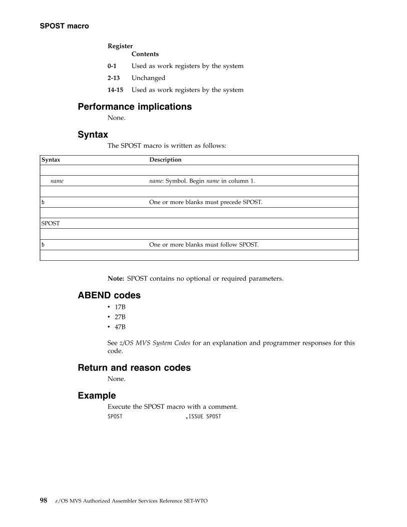
RegisterContents
0-1 Used as work registers by the system
2-13 Unchanged
14-15 Used as work registers by the system
Performance implicationsNone.
SyntaxThe SPOST macro is written as follows:
Syntax Description
name name: Symbol. Begin name in column 1.
� One or more blanks must precede SPOST.
SPOST
� One or more blanks must follow SPOST.
Note: SPOST contains no optional or required parameters.
ABEND codesv 17Bv 27Bv 47B
See z/OS MVS System Codes for an explanation and programmer responses for thiscode.
Return and reason codesNone.
ExampleExecute the SPOST macro with a comment.SPOST ,ISSUE SPOST
SPOST macro
98 z/OS MVS Authorized Assembler Services Reference SET-WTO

Chapter 8. SRBSTAT — Save, restore, or modify SRB status
Description
Note: IBM recommends that you use the following macros rather than SRBSTAT:v SUSPEND - Suspend Execution of an SRBv RESUME - Resume or Purge a Suspended SRB
The SRBSTAT macro allows the caller to save, restore, and modify the status of anSRB in a caller-supplied save area. Control returns from the SRBSTAT macro inprimary ASC mode.
EnvironmentThese are the requirements for the caller:
Environmental factor RequirementMinimum authorization: Supervisor state, key 0Dispatchable unit mode: SRB for SAVE or RESTORE options.
SRB or TASK for MODIFY option.Cross memory mode: PASN=HASN=SASNAMODE: 24- or 31-bitASC mode: PrimaryInterrupt status: Enabled for I/O and external interruptsLocks: No locks heldControl parameters: Must be in primary address space
Programming requirementsNone.
RestrictionsThe caller of SRBSTAT RESTORE must not change PASID before the request; theRESTORE will restore the PASID saved by the earlier SAVE request.
Input register informationBefore issuing the SRBSTAT macro, the caller must ensure that general purposeregister 13 points to a standard 72-byte save area addressable in primary mode.
Output register informationWhen control returns to the caller, the GPRs contain the following.
When SAVE is specified:
RegisterContents
0 Unchanged
1 Used as a work register by the system
2-14 Unchanged
© Copyright IBM Corp. 1988, 2017 99

15 Return code
When RESTORE is specified:
RegisterContents
0-13 Restored
14 Unchanged
15 Return code
When MODIFY is specified:
RegisterContents
0-14 Unchanged
15 Return code
When control returns to the caller, the ARs contain:
RegisterContents
0-1 Used as work registers by the system
2-13 Unchanged
14-15 Used as work registers by the system
Performance implicationsNone.
SyntaxThe SRBSTAT macro is written as follows:
Syntax Description
name name: Symbol. Begin name in column 1.
� One or more blanks must precede SRBSTAT.
SRBSTAT
� One or more blanks must follow SRBSTAT.
SAVE
RESTORE
MODIFY
,STSV=stsv addr stsv addr: RX-type address or register (1) - (12), register (1) preferred.
SRBSTAT macro
100 z/OS MVS Authorized Assembler Services Reference SET-WTO

Syntax Description
,STSV=0
,NEWFRR=addr addr: RX-type address or register (0) or (2) - (12), register (0) preferred.
,PRGAT=pat addr pat addr: RX-type address or register (2) - (12), register (2) preferred.
ParametersThe parameters are explained as follows:
SAVERESTOREMODIFY
Specifies whether a save, restore, or modify operation is requested. For SAVEor RESTORE, status that is saved or restored includes:v General, floating point, and vector registersv Control registers 3 and 4v CPU affinity maskv Related ASID/TCBv Timing informationv FRR stackv PCLINK stack header
If SAVE is specified, only caller's registers 1 and 15 are destroyed. Register 1 isused to hold an FRR parameter area address if NEWFRR is also specified andregister 15 is used for a return code. The PCLINK stack header is saved andzeroed.
If RESTORE is specified, registers 0-13 are restored. The contents of register 14are the same as when RESTORE was entered. The current PCLINK stackheader must be zero; the saved one is restored.
If MODIFY is specified, registers 0-14 are unchanged and register 15 contains areturn code.
Note:
1. On entry to RESTORE, the PCLINK stack header must be zero.2. RESTORE cannot be used in an FRR.3. RESTORE returns to its caller and not to the caller of SAVE.4. SRBSTAT does not save and restore access registers, extended authorization
index (EAX) value, and linkage stack and access list status.5. If vector status is saved, it can be restored only to an SRB that has
previously issued IEAFP START.
,STSV=stsv addrSpecifies the address of the save area to be used for the SAVE, RESTORE, orMODIFY operation. The size of this save area is contained in field SVTSSTSVof the SVT control block. The savearea can be in private pageable storage, butit must be addressable from the home address space and it must begin on adoubleword boundary. For RESTORE or MODIFY, the savearea must containvalid status.
SRBSTAT macro
Chapter 8. SRBSTAT — Save, restore, or modify SRB status 101
||
|
|
|
|
|
|
|
||||
|||
||
|
|
|
|
||
||
|

,STSV=0Specifies that the current status is to be modified. This parameter is valid onlywith MODIFY.
For MODIFY, an existing SRB status savearea or the current status is modified.Only the purge ASID/TCB information can be modified. All registers are savedand restored except register 15, which contains a return code.
HexadecimalCode
Meaning
00 The modify function was successfully completed.
,NEWFRR=addrSpecifies the address of an FRR established with MODE=FULLXM. For SAVE,the address of the FRR parameter area is returned to the caller in register 1.The first word of the parameter area contains the address of the SRB statussavearea being used.
For RESTORE, the FRR address is used only if the saved status cannot bereinstated on the current processor. An SRB with the FRR option is scheduledspecifying this FRR.
For MODIFY, this parameter is invalid.
,PRGAT=pat addrSpecifies the address of a 6-byte area of storage, currently addressable in theprimary address space, that contains the new purge ASID/TCB. Bytes 1 and 2contain the ASID; bytes 3-6 contain the TCB address. This parameter isrequired with MODIFY but is invalid with SAVE or RESTORE.
ABEND codesv 05E
See z/OS MVS System Codes for an explanation and programmer responses for thiscode.
Return and reason codesNone.
SRBSTAT macro
102 z/OS MVS Authorized Assembler Services Reference SET-WTO

Chapter 9. SRBTIMER — Establish time limit for systemservice
DescriptionThe SRBTIMER macro is used to establish a time limit for a system service runningin SRB mode. Time accumulates while the service is running; when the time limitexpires, the service abends with a system completion code of X'05B'. The servicecan retry following the 05B ABEND.
The caller can cancel an established time limit by reissuing the macro andspecifying a time limit of zero. The caller can also override the established timelimit with a subsequent SRBTIMER macro.
EnvironmentThese are the requirements for the caller:
Environmental factor RequirementMinimum authorization: Supervisor state and key 0Dispatchable unit mode: SRBCross memory mode: PASN=HASN=SASNAMODE: 24- or 31-bitASC mode: PrimaryInterrupt status: Enabled for I/O and external interruptsLocks: No requirementControl parameters: Must be in primary address space
Programming requirementsNone.
RestrictionsNone.
Input register informationBefore issuing the SRBTIMER macro, the caller must ensure that general purposeregister 13 points to a standard 72-byte save area addressable in primary mode.
Output register informationWhen control returns to the caller, the GPRs contain:
RegisterContents
0-1 Used as work registers by the system
2-13 Unchanged
14 Used as a work register by the system
15 Return code
When control returns to the caller, the ARs contain:
© Copyright IBM Corp. 1988, 2017 103

RegisterContents
0-1 Used as work registers by the system
2-13 Unchanged
14-15 Used as work registers by the system
Performance implicationsNone.
SyntaxThe SRBTIMER macro is written as follows:
Syntax Description
name name: Symbol. Begin name in column 1.
� One or more blanks must precede SRBTIMER.
SRBTIMER
� One or more blanks must follow SRBTIMER.
LIMIT=stor addr stor addr: RX-type address or register (0) or (2) - (12).
,ERRET=err rtn addr err rtn addr: RX-type address or register (2) - (12).
ParametersThe parameters are explained as follows:
LIMIT=stor addrSpecifies the virtual storage address of a doubleword field on a doublewordboundary that contains the time limit. The time limit is in the form of a signed64-bit binary number and must be positive in order for time to elapse. Anegative number causes immediate expiration of the time limit. Bit 51 of thebinary number is approximately equivalent to one microsecond. If you specifya value greater than 208 days, the control program changes the value to 208days. The resolution of the timer is model dependent. See Principles ofOperation for details concerning the timer facility.
,ERRET=err rtn addrSpecifies the address of the routine to be given control when the SRBTIMERfunction encounters damaged clocks.
ABEND codesNone.
SRBTIMER macro
104 z/OS MVS Authorized Assembler Services Reference SET-WTO

Return codesWhen SRBTIMER macro returns control to your program, GPR 15 contains ahexadecimal return code.
Table 15. Return Codes for the SRBTIMER Macro
Return Code Meaning and Action
00 Meaning: The time limit was successfully established.
Action: None.
10 Meaning: The issuer is not in SRB mode. No timing is performed.
Action: Ensure that the requesting program is running in SRB mode, or useSTIMER or STIMERM instead.
SRBTIMER macro
Chapter 9. SRBTIMER — Establish time limit for system service 105

SRBTIMER macro
106 z/OS MVS Authorized Assembler Services Reference SET-WTO

Chapter 10. STATUS — Control dispatchability orprocess-must-complete state
DescriptionThe STATUS macro with the START or STOP option starts or stops a unit or unitsof work. The STATUS macro with the SET or RESET option places a program inprocess-must-complete mode or ends process-must-complete mode.Process-must-complete mode postpones delays from the following:v Asynchronous exitsv Asynchronous abends (CALLRTM TYPE=ABTERM for tasks or CALLRTM
TYPE=SRBTERM for preemptable SRBs)v Status stops (by issuing the STATUS macro with the STOP option)v Timer exitsv Dumpingv Swappingv Attention exits
Process-must-complete mode prevents a CANCEL command from stopping aprogram already running but it does not postpone external interrupts or interruptsfrom I/O.
The description of the STATUS macro has two parts: the START/STOP option andthe SET/RESET option. z/OS MVS Programming: Assembler Services ReferenceIAR-XCT describes the STATUS macro START and STOP options with theexception of the SRB and ASID parameters. These parameters, which are availableonly to supervisor state and key 0 callers, allow the caller to manipulate thedispatchability status or SRBs.
See z/OS MVS Programming: Authorized Assembler Services Guide for moreinformation on how to use the STATUS macro SET and RESET options and z/OSMVS Programming: Assembler Services Guide for more information on how to use theSTATUS macro START and STOP options.
EnvironmentThe requirements for the caller issuing STATUS with the START or STOPparameters are:
Environmental factor RequirementMinimum authorization: Problem state or supervisor state, with any PSW key. For
SRB and ASID parameters, supervisor state and PSW key 0.Dispatchable unit mode: TaskCross memory mode: PASN=HASN=SASN or PASN¬=HASN¬=SASNAMODE: 31-bitASC mode: Primary or access register (AR)Interrupt status: Enabled or disabled for I/O and external interruptsLocks: No locks heldControl parameters: No requirements
© Copyright IBM Corp. 1988, 2017 107

The requirements for the caller issuing STATUS with the SET or RESET parametersare:
Environmental factor RequirementMinimum authorization: Supervisor state, with PSW key 0.Dispatchable unit mode: Task or preemptable SRB.Cross memory mode: PASN=HASN=SASN or PASN¬=HASN¬=SASNAMODE: 31-bitASC mode: v For task mode: Primary or access register (AR).
v For SRB mode: Primary.Interrupt status: Enabled or disabled for I/O and external interruptsLocks: No locks required. The Local, CMS, and/or CPU locks may
be held.Control parameters: No requirements
Programming requirementsNone.
RestrictionsExcept for the TCB, all input parameters to this macro can reside in storage above16 megabytes.
While in process-must-complete mode, a task must not:v Issue STATUS STOP,SRB or STATUS START,SRBv Request the LOCAL lock unconditionallyv Issue an SVC or invoke services that issue SVCsv Issue the WAIT macro or invoke services that issue WAITs
While in process-must-complete mode, a preemptable SRB must not:v Request the LOCAL lock unconditionallyv Pausev Suspend
These restrictions also apply to any routine invoked by a program inprocess-must-complete mode.
Process-must-complete mode is not preserved across a retry from an ESTAE-typeroutine. However, it is preserved across a retry from an FRR, unless the FRR is anEUT FRR and the environment at the time of the abend was Enabled, Unlocked,and in Task mode.
For the START or STOP parameters, the caller cannot have an EUT FRRestablished.
Register informationAfter the caller issues the macro, the system might use some registers as workregisters or might change the contents of some registers. When the system returnscontrol to the caller, the contents of these registers are not the same as they werebefore the macro was issued. Therefore, if the caller depends on these registerscontaining the same value before and after issuing the macro, the caller must savethese registers before issuing the macro and restore them after the system returnscontrol.
STATUS macro
108 z/OS MVS Authorized Assembler Services Reference SET-WTO

When control returns to the caller, the GPRs contain:
RegisterContents
0-1 Used as work registers by the system
2-13 Unchanged
14 Used as a work register by the system
15 Return code
When control returns to the caller, the access registers (ARs) contain:
RegisterContents
0-1 Used as work registers by the system
2-13 Unchanged
14-15 Used as work registers by the system
Performance implicationsUsing STATUS will degrade performance of the calling program's address spacewhile STATUS runs.
Remaining in process-must-complete mode for an extended period of time willdegrade the performance of other programs waiting to use global resources thatthe program in this mode holds.
START/STOP options
SyntaxThe START/STOP options of the STATUS macro are written as follows:
Syntax Description
name name: Symbol. Begin name in column 1.
� One or more blanks must precede STATUS.
STATUS
� One or more blanks must follow STATUS.
START
STOP
,TCB=tcb addr tcb addr: RX-type address or address in register (2) - (12), or 0.
,SRB ASID addr: RX-type address or address in register (2) - (12).
,SRB, ASID=ASID addr Note: ASID may only be specified with START.
STATUS macro
Chapter 10. STATUS — Control dispatchability or process-must-complete state 109

Syntax Description
,RELATED=value value: Any valid macro keyword specification.
ParametersThe parameters are described as follows:
STARTSTOP
Specifies that the task identified in the TCB parameter is to be stopped (STOP)or started (START). If you omit the TCB parameter, all subtasks of theoriginating task are stopped or started.
Note: The STOP parameter does not ensure that the subtask is stopped whencontrol returns to the issuer. A subtask can have a “stop deferred” conditionthat would cause that particular subtask to remain dispatchable until stops areno longer deferred. In an MP environment, it would be possible to have a taskissue the STATUS macro with the STOP parameter and resume processingwhile the subtask (for which the STOP was issued) is redispatched to anotherprocessor.
,TCB=tcb addr,SRB,SRB,ASID=ASID addr
Specifies the status of the stop/start function:
TCB Specifies the address of a fullword on a fullword boundary containingthe address of the TCB that is to have its START/STOP count adjusted.
Note: The TCB resides in storage below 16 megabytes.
SRB Specifies that the STOP and START functions affect the dispatchabilityof system-level SRBs; all tasks in the address space except the caller'sare also set or reset nondispatchable. For START, the ASID addrspecifies the address of a halfword containing the address spaceidentifier. If ASID is not specified, the action is taken against thecaller's address space.
,RELATED=valueSpecifies information used to self-document macros by “relating” functions orservices to corresponding functions or services. The format and contents of theinformation specified are at the discretion of the user and may be any validcoding values.
Return codesWhen control returns to the caller, register 15 contains one of the followinghexadecimal return codes:
Table 16. Return Codes for the STATUS Macro
Return Code Meaning and Action
00 Meaning: Processing completed successfully.
Action: None required.
STATUS macro
110 z/OS MVS Authorized Assembler Services Reference SET-WTO
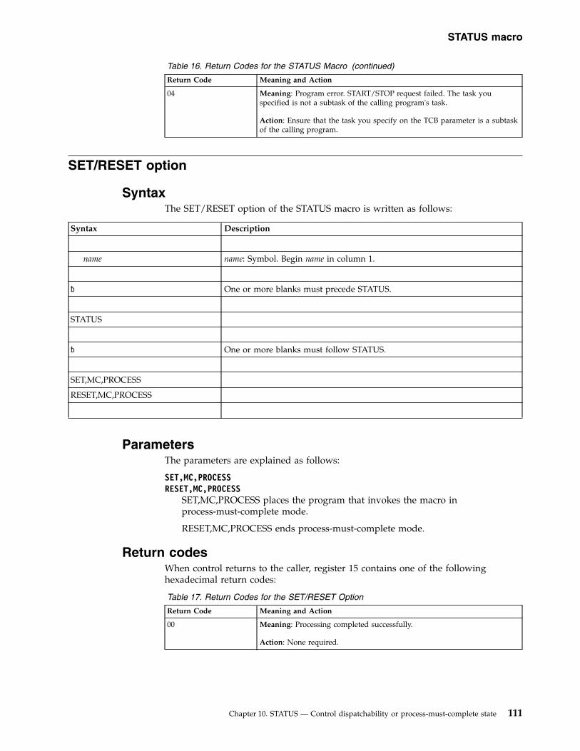
Table 16. Return Codes for the STATUS Macro (continued)
Return Code Meaning and Action
04 Meaning: Program error. START/STOP request failed. The task youspecified is not a subtask of the calling program's task.
Action: Ensure that the task you specify on the TCB parameter is a subtaskof the calling program.
SET/RESET option
SyntaxThe SET/RESET option of the STATUS macro is written as follows:
Syntax Description
name name: Symbol. Begin name in column 1.
� One or more blanks must precede STATUS.
STATUS
� One or more blanks must follow STATUS.
SET,MC,PROCESS
RESET,MC,PROCESS
ParametersThe parameters are explained as follows:
SET,MC,PROCESSRESET,MC,PROCESS
SET,MC,PROCESS places the program that invokes the macro inprocess-must-complete mode.
RESET,MC,PROCESS ends process-must-complete mode.
Return codesWhen control returns to the caller, register 15 contains one of the followinghexadecimal return codes:
Table 17. Return Codes for the SET/RESET Option
Return Code Meaning and Action
00 Meaning: Processing completed successfully.
Action: None required.
STATUS macro
Chapter 10. STATUS — Control dispatchability or process-must-complete state 111

Table 17. Return Codes for the SET/RESET Option (continued)
Return Code Meaning and Action
04 Meaning: Program error. You issued STATUS SET,MC,PROCESS but it hadalready been issued.
Action: Do not issue STATUS SET,MC,PROCESS again until you haveissued STATUS RESET,MC,PROCESS.
08 Meaning: Program error. You issued STATUS RESET,MC,PROCESS but hadnever issued STATUS SET,MC,PROCESS.
Action: Issue STATUS SET,MC,PROCESS before issuing STATUSRESET,MC,PROCESS.
0C Meaning: Program error. You issued STATUS SET,MC,PROCESS whilerunning under a non-preemptable SRB.
Action: Avoid issuing STATUS SET,MC,PROCESS from a non-preemptableSRB.
10 Meaning: Program error. You issued STATUS RESET,MC,PROCESS whilerunning under a non-preemptable SRB.
Action: Avoid issuing STATUS SET,MC,PROCESS from a non-preemptableSRB.
ExampleCause a program process to enter, then end, process-must-complete mode.* Chaining for a nonreenterable program, but note that STATUS SET,MC,* PROCESS and STATUS RESET,MC,PROCESS do not require that a savearea* be provided.
SETPMC CSECTSETPMC AMODE 31SETPMC RMODE ANY
STM 14,12,12(13) SAVE REGISTERSLR 12,15 GET ENTRY POINT ADDRESSUSING SETPMC,12 ESTABLISH ADDRESSABILITYST 13,SAVEAREA+4 SAVE REGISTER 13LR 2,13 GET CALLER SAVEAREA ADDRESSLA 13,SAVEAREA SET UP OUR SAVEAREA ADDRESSST 13,8(2) SAVE SAVEAREA ADDRESS IN CALLER
SAVEAREAMODESET MODE=SUP,KEY=ZERO GET INTO SUPERVISOR STATE, KEY 0STATUS SET,MC,PROCESS SET PMC MODELTR 15,15 CHECK RETURN CODEBNZ BADSET NOT SUCCESSFUL, GO HANDLE...
** Perform processing that requires process-must-complete mode...* Note: This processing must not request the local lock and* must not issue any SVCs or issue a WAIT.**RESET STATUS RESET,MC,PROCESS RESET PMC MODE
LTR 15,15 PMC MODE HAD ALREADY BEEN RESET,ALREADY OUT OF PMC MODE
BNZ BADRESET NOT SUCCESSFUL, GO HANDLE...*EXIT DS 0H
MODESET MODE=PROB,KEY=NZERO GET OUT OF SUPERVISOR STATE, KEY 0L 13,4(13) RESTORE REGISTER 13L 14,12(13) RESTORE REGISTER 14LM 0,12,20(13) RESTORE REGISTERS 0 THRU 12SLR 15,15 SET RETURN CODE 0 IN REGISTER 15BR 14 RETURN TO THE CALLER
BADSET DS 0H
STATUS macro
112 z/OS MVS Authorized Assembler Services Reference SET-WTO

** Perform appropriate processing for nonzero return code from* STATUS SET,MC,PROCESS.*
B EXITBADRESET DS 0H** Perform appropriate processing for nonzero return code from* STATUS RESET,MC,PROCESS.*
B EXITSAVEAREA DC 18F’0’ 18-WORD SAVEAREA
END SETPMC
STATUS macro
Chapter 10. STATUS — Control dispatchability or process-must-complete state 113

STATUS macro
114 z/OS MVS Authorized Assembler Services Reference SET-WTO

Chapter 11. STORAGE — Obtain and release storage
DescriptionThe STORAGE macro requests that the system obtain or release an area of virtualstorage in the primary address space (by default), or in the address space definedthrough the ALET parameter. The two functions of the macro are:v STORAGE OBTAIN, which requests an area of virtual storage.v STORAGE RELEASE, which releases an area of virtual storage.
The STORAGE macro is also described in z/OS MVS Programming: AssemblerServices Reference IAR-XCT, with the exception of the ALET, TCBADDR, andOWNER parameters.
If you use STORAGE OBTAIN to request real storage backing above 2 gigabytes,but your system does not support 64-bit storage, your request will be treated as arequest for backing above 16 megabytes, even on earlier releases of z/OS that donot support backing above 2 gigabytes. However, boundary requirements indicatedby the CONTBDY and STARTBDY parameters will be ignored by earlier releases ofz/OS.
EnvironmentThe requirements for the caller are:
Environmental factor RequirementMinimum authorization: For subpools 0-127: problem state and PSW key 8-15.
For subpools 131 and 132, one or more of the following:
v Supervisor state
v PSW key 0-7
v PSW key mask (PKM) that allows the calling program toswitch its PSW key to match the key of the storage to beobtained or released.
v APF-authorization.
For the ALET parameter and the TCBADDR parameter,either of the following:
v Supervisor state
v PSW key 0-7
For LINKAGE=SYSTEM or LINKAGE=SVC: for all othersubpools, one or more of the following:
v Supervisor state
v PSW key 0-7
v APF-authorization.
For LINKAGE=BRANCH or LINKAGE=GLOBALBRANCH:Supervisor state and PSW key 0.
To issue a subpool release for subpool 0: PSW key 0.
© Copyright IBM Corp. 1988, 2017 115
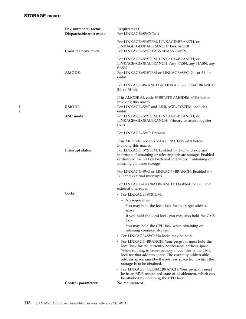
Environmental factor RequirementDispatchable unit mode: For LINKAGE=SVC: Task
For LINKAGE=SYSTEM, LINKAGE=BRANCH, orLINKAGE=GLOBALBRANCH: Task or SRB
Cross memory mode: For LINKAGE=SVC: PASN=HASN=SASN
For LINKAGE=SYSTEM, LINKAGE=BRANCH, orLINKAGE=GLOBALBRANCH: Any PASN, any HASN, anySASN
AMODE: For LINKAGE=SYSTEM or LINKAGE=SVC: 24- or 31- or64-bit
For LINKAGE=BRANCH or LINKAGE=GLOBALBRANCH:24- or 31-bit.
If in AMODE 64, code SYSSTATE AMODE64=YES beforeinvoking this macro.
RMODE: For LINKAGE=SVC and LINKAGE=SYSTEM, includes64-bit
ASC mode: For LINKAGE=SYSTEM, LINKAGE=BRANCH, orLINKAGE=GLOBALBRANCH: Primary or access register(AR).
For LINKAGE=SVC: Primary
If in AR mode, code SYSSTATE ASCENV=AR beforeinvoking this macro.
Interrupt status: For LINKAGE=SYSTEM: Enabled for I/O and externalinterrupts if obtaining or releasing private storage. Enabledor disabled for I/O and external interrupts if obtaining orreleasing common storage.
For LINKAGE=SVC or LINKAGE=BRANCH: Enabled forI/O and external interrupts.
For LINKAGE=GLOBALBRANCH: Disabled for I/O andexternal interrupts.
Locks: v For LINKAGE=SYSTEM:
– No requirement.
– You may hold the local lock for the target addressspace.
– If you hold the local lock, you may also hold the CMSlock.
– You may hold the CPU lock when obtaining orreleasing common storage.
v For LINKAGE=SVC: No locks may be held.
v For LINKAGE=BRANCH: Your program must hold thelocal lock for the currently addressable address space.When running in cross-memory mode, this is the CMLlock for that address space. The currently addressableaddress space must be the address space from which thestorage is to be obtained.
v For LINKAGE=GLOBALBRANCH: Your program mustbe in an MVS-recognized state of disablement, which canbe attained by obtaining the CPU lock.
Control parameters: No requirement.
STORAGE macro
116 z/OS MVS Authorized Assembler Services Reference SET-WTO
|||

Programming requirementsNone.
RestrictionsNone.
Register informationRegister usage varies depending on the type of STORAGE request. For specificinformation, see the descriptions of STORAGE OBTAIN and STORAGE RELEASE.
Performance implicationsNone.
STORAGE OBTAINThe STORAGE macro with the OBTAIN parameter requests that the systemallocate an area of virtual storage to the specified task. The length you specifymust not exceed the length available. The length available depends on how muchstorage has already been allocated and, for subpools 0 - 127, 129-132, 240, and250-252, the region size. For some subpools, the system releases the storage whenthe owning task terminates. For other subpools, you must issue STORAGERELEASE or FREEMAIN to release them. Before obtaining storage, be sure to read“Selecting the Right Subpool for Your Virtual Storage Request” in z/OS MVSProgramming: Authorized Assembler Services Guide.
Note:
1. When you obtain storage, the system clears the requested storage to zeros ifyou obtain either:v 8192 bytes or more from a pageable, private storage subpool and
PAGEFRAMESIZE1M is not specified on the LOC keyword.v 4096 bytes or more from a pageable, private storage subpool, with
BNDRY=PAGE or STARTBDY=12 specified and PAGEFRAMESIZE1M is notspecified on the LOC keyword.In all other cases, you must not assume that the storage is cleared to zeros.The caller can specify CHECKZERO=YES to detect these and other caseswhere the system clears the requested storage to zeros.
2. Do not allocate key 8 or key 9 storage in the common area because it can beread or written by any program in any address space.
Input register information for LINKAGE=SYSTEMBefore issuing the STORAGE macro with the OBTAIN parameter, the caller doesnot have to place any information into any register unless using it in registernotation for a particular parameter, or using it as a base register.
Output register information for LINKAGE=SYSTEMWhen control returns to the caller, the GPRs contain:
RegisterContents
STORAGE macro
Chapter 11. STORAGE — Obtain and release storage 117
||
||

0 For a successful request in which maximum and minimum lengths werespecified, contains the length of the storage obtained. Otherwise, used as awork register by the system.
1 The address of the allocated storage when STORAGE OBTAIN issuccessful; otherwise, used as a work register by the system.
Note: A successful STORAGE OBTAIN will return a 64-bit pointer to theobtained area (bits 0-32 will be zero).
2-13 Unchanged.
14 Used as a work register by the system.
15 Contains the return code.
When control returns to the caller, the access registers (ARs) contain:
RegisterContents
0 Used as a work register by the system.
1 The ALET value if you specified the ALET parameter and the STORAGEOBTAIN is successful.
0 if you did not specify the ALET parameter and the STORAGE OBTAIN issuccessful.
Otherwise, used as a work register by the system.
2-13 Unchanged.
14-15 Used as work registers by the system.
Some callers depend on register contents remaining the same before and afterissuing a service. If the system changes the contents of registers on which the callerdepends, the caller must save them before issuing the service, and restore themafter the service returns control.
Input register information for LINKAGE=SVCBefore issuing the STORAGE macro with LINKAGE=SVC, the caller does not haveto place any information into any register unless using it in register notation for aparticular parameter, or using it as a base register.
Output register information for LINKAGE=SVCWhen control returns to the caller the GPRs contain:
RegisterContents
0 For a successful request, contains the length of the storage obtained.Otherwise, used as a work register by the system.
1 The address of the allocated storage when STORAGE is successful;otherwise, used as a work register by the system.
Note: A successful STORAGE OBTAIN will return a 64-bit pointer to theobtained area (bits 0-32 will be zero).
2-13 Unchanged.
14 Used as a work register by the system.
STORAGE macro
118 z/OS MVS Authorized Assembler Services Reference SET-WTO

15 Contains the return code.
When control returns to the caller, the access registers (ARs) contain:
RegisterContents
0-1 Used as work registers by the system.
2-13 Unchanged.
14-15 Used as work registers by the system.
Input register information for LINKAGE=BRANCHBefore issuing the STORAGE macro with LINKAGE=BRANCH, the caller mustensure that the following GPRs contain the specified information:
RegisterContents
4 The address of the input TCB, if you are obtaining private storage.
If your program is not running in cross-memory mode, setting GPR 4 to 0identifies the input TCB as the TCB of the current task.
If your program is running in cross-memory mode, set GPR 4 to 0 or theaddress of a TCB in the currently addressable address space.
Setting the GPR 4 to 0 identifies the input TCB as the TCB that owns thecross-memory resources for the currently addressable address space (taskwhose TCB address is in ASCBXTCB).
For an explanation of the term input TCB, and to determinesystem-assigned defaults for private storage ownership, see the informationabout selecting the right subpool for virtual storage requests in z/OS MVSProgramming: Authorized Assembler Services Guide.
7 The address of the ASCB for the currently addressable address space.
Output register information for LINKAGE=BRANCHWhen control returns to the caller, the GPRs contain:
RegisterContents
0 For a successful request, contains the length of the storage obtained.Otherwise, used as a work register by the system. Storage obtained.
1 The address of the allocated storage when STORAGE is successful;otherwise, used as a work register by the system.
Note: A successful STORAGE OBTAIN will return a 64-bit pointer to theobtained area (bits 0-32 will be zero).
2 Unchanged.
3 Used as a work register by the system.
4-13 Unchanged.
14 Used as a work register by the system.
15 Contains the return code.
STORAGE macro
Chapter 11. STORAGE — Obtain and release storage 119

When control returns to the caller, the ARs contain:
RegisterContents
0-1 Used as work registers by the system.
2-13 Unchanged.
14-15 Used as work registers by the system.
Input register information for LINKAGE=GLOBALBRANCHBefore issuing the STORAGE macro with LINKAGE=GLOBALBRANCH, the callerdoes not have to place any information into any register unless using it in registernotation for a particular parameter, or using it as a base register.
Output register information for LINKAGE=GLOBALBRANCHWhen control returns to the caller, the GPRs contain:
RegisterContents
0 For a successful request, contains the length of the storage obtained.Otherwise, used as a work register by the system.
1 The address of the allocated storage when STORAGE is successful;otherwise, used as a work register by the system.
Note: A successful STORAGE OBTAIN will return a 64-bit pointer to theobtained area (bits 0-32 will be zero).
2 Unchanged.
3-4 Used as work registers by the system.
5-13 Unchanged.
14 Used as a work register by the system.
15 Contains the return code.
When control returns to the caller, the ARs contain:
RegisterContents
0-1 Used as work registers by the system.
2-13 Unchanged.
14-15 Used as work registers by the system.
Some callers depend on register contents remaining the same before and afterissuing a service. If the system changes the contents of registers on which the callerdepends, the caller must save them before issuing the service, and restore themafter the service returns control.
SyntaxThe OBTAIN option of the STORAGE macro is written as follows:
Syntax Description
STORAGE macro
120 z/OS MVS Authorized Assembler Services Reference SET-WTO

Syntax Description
name name: Symbol. Begin name in column 1.
⌂ One or more blanks must precede STORAGE.
STORAGE
⌂ One or more blanks must follow STORAGE.
OBTAIN
,LENGTH=length value length value: Symbol, decimal number, or register (0),(2)-(12).
,LENGTH=(max length,min length) max length: Symbol, decimal number, or register (0), (2) -(12).
min length: Symbol, decimal number, or register (1) - (12).
,ADDR=stor addr stor addr: RX-type address or register (1) - (12).
Default: ADDR=(1).
,INADDR=stor addr stor addr: RX-type address or register (1) - (12).
Note: This parameter can only be specified withLOC=EXPLICIT.
,SP=subpool number subpool number: Symbol, decimal number, or register(2)-(12), (15).
Default: SP=0.
,ALET=alet-value alet-value: Decimal number, RX-type address, or accessregister(1)-(12)
Default: ALET=0.
,BNDRY=DBLWD Default: BNDRY=DBLWD
,BNDRY=PAGE
,CONTBDY=containing_bdy containing_bdy: Decimal number 3-31 or register (2) - (12).
,STARTBDY=starting_bdy starting_bdy: Decimal number 3-31 or register (2) - (12).
,KEY=key number key number: Decimal number 0-15 or register (2) - (12).
Note 1: KEY is valid only when SP is specified.
Note 2: You cannot specify both KEY andCALLRKY=YES.
STORAGE macro
Chapter 11. STORAGE — Obtain and release storage 121

Syntax Description
,CALLRKY=NO Default: CALLRKY=NO
,CALLRKY=YES Note: You cannot specify both CALLRKY=YES and KEY.
,LOC=24
,LOC=(24,31)
,LOC=(24,64)
,LOC=31
,LOC=(31,31)
,LOC=(31,64)
,LOC=(31,PAGEFRAMESIZE1MB)
,LOC=RES Default: LOC=RES
,LOC=(RES,31)
,LOC=(RES,64)
,LOC=EXPLICIT Note: You must specify the INADDR parameter with
,LOC=(EXPLICIT,24) EXPLICIT.
,LOC=(EXPLICIT,31)
,LOC=(EXPLICIT,64)
,LOC=(EXPLICIT,PAGEFRAMESIZE1MB)
,LINKAGE=SYSTEM Default: LINKAGE=SYSTEM
,LINKAGE=SVC
,LINKAGE=BRANCH
,LINKAGE=GLOBALBRANCH
,OWNER=HOME Default: OWNER=HOME
,OWNER=PRIMARY
,OWNER=SECONDARY
,OWNER=SYSTEM
,OWNERASID=decimal number
,OWNERASID=register(2)-(12)
,OWNERASID=RS-type address
,CAUB=CURRENT Default: CAUB=CURRENT
,CAUB=ADDRSPACE
,RTCD=rtcd addr rtcd addr: RX-type address or register (2) - (12) or (15).
Default: RTCD=(15).
,COND=YES Default: COND=NO
,COND=NO
STORAGE macro
122 z/OS MVS Authorized Assembler Services Reference SET-WTO

Syntax Description
,CHECKZERO=YES Default: CHECKZERO=NO
,CHECKZERO=NO
,BACK=BYSPT Default: BACK=BYSPT
,BACK=NONE
,BACK=ALL
,FIX=NONE Default: FIX=NONE
,FIX=SHORT
,FIX=LONG
,TCBADDR=tcbaddress tcbaddress: RS-type address or register (2) - (12).
Default: See “Selecting the Right Subpool for YourVirtual Storage Request” in z/OS MVS Programming:Authorized Assembler Services Guide for the possibledefault values.
,EXECUTABLE=YES Default: EXECUTABLE=YES
,EXECUTABLE=NO
,RELATED=value value: Any valid macro parameter specification.
ParametersThe parameters are explained as follows:
OBTAINRequests that the system obtain virtual storage.
,LENGTH=length value,LENGTH=(max length,min length)
Specifies the amount of storage the system is to obtain. length value specifiesthe length, in bytes, of the requested virtual storage. max length and min lengthspecify the maximum and minimum amounts of storage. These numbersshould be a multiple of 8; if they are not, the system uses the next highermultiple of 8.
,ADDR=stor addrSpecifies the location where the system is to return the address of the storage itallocates.
,INADDR=stor addrSpecifies the desired virtual address for the storage to be obtained. When youspecify INADDR, you must specify EXPLICIT on the LOC parameter.
Note:
STORAGE macro
Chapter 11. STORAGE — Obtain and release storage 123
|
|

1. The address specified on INADDR must be on a doubleword boundary.2. Make sure that the virtual storage address specified on INADDR and the
central storage backing specified on the LOC=EXPLICIT parameter are avalid combination. For example, if the address specified on INADDR is forstorage above 16 megabytes, specify LOC=EXPLICIT orLOC=(EXPLICIT,ANY). Valid combinations include:v virtual above, central anyv virtual any, central anyv virtual below, central belowv virtual below, central any
,SP=subpool numberSpecifies the subpool number for the storage. (See z/OS MVS Programming:Authorized Assembler Services Guide for a list of valid subpools.) If you specify aregister, the subpool number must be in bits 24-31 of the register, with bits 0-23set to zero. If you omit this parameter, the system uses the default, which issubpool 0.
Note:
1. Callers executing in supervisor state and key 0, who specify subpool 0, willobtain storage from subpool 252. Therefore, when requesting a dump ofthis storage through the SDUMP or SDUMPX macro, they must specifysubpool 252 rather than zero.
2. Storage requested from subpools 240 and 250 are translated to subpool 0requests.
,ALET=alet-valueSpecifies the ALET of the target address space — the address space in whichthe storage is to be obtained. The ALET must be on the caller's primaryaddress space access list (PASN-AL) or dispatchable unit access list (DU-AL)and, if the ALET identifies a private entry, the caller must be authorized to thetarget address space through the extended authorization index (EAX). Formore information, see z/OS MVS Programming: Extended Addressability Guide. Ifyou omit this parameter, the system assumes the target address space is in theprimary address space.
The ALET parameter is valid only with LINKAGE=SYSTEM.
,BNDRY=DBLWD,BNDRY=PAGE
Specifies that alignment on a doubleword boundary (DBLWD) or alignmentwith the start of a virtual page on a 4K boundary (PAGE) is required for thestart of a requested area.
If the request specifies one of the LSQA or SQA subpools, the system ignoresthe BNDRY=PAGE keyword. Requests for storage from these subpools are thenfulfilled from a single page, unless the request is greater than a page. See z/OSMVS Programming: Authorized Assembler Services Guide for a list of the LSQAand SQA subpools.
The default is BNDRY=DBLWD.
,CONTBDY=containing_bdySpecifies the boundary the obtained storage must be contained within. Specifya power of 2 that represents the containing boundary. Supported values are3-31. For example, CONTBDY=10 means the containing boundary is 2**10, or
STORAGE macro
124 z/OS MVS Authorized Assembler Services Reference SET-WTO
1024 bytes. The containing boundary must be at least as large as the maximumrequested boundary. The obtained storage will not cross an address that is amultiple of the requested boundary.
If a register is specified, the value must be in bits 24-31 of the register. Do notspecify CONTBDY on a variable-length request.
CONTBDY is not valid with LOC=EXPLICIT or BNDRY=PAGE.
CONTBDY applies to all subpools.
If you omit this parameter, there is no containing boundary.
,STARTBDY=starting_bdySpecifies the boundary the obtained storage must start on. Specify a power of 2that represents the start boundary. Supported values are 3 - 31. For example,STARTBDY=10 means the start boundary is 2**10, or 1024 bytes. The obtainedstorage will begin on an address that is a multiple of the requested boundary.
If a register is specified, the value must be in bits 24-31 of the register. Do notspecify STARTBDY on a variable-length request.
STARTBDY is not valid with LOC=EXPLICIT or BNDRY=PAGE.
STARTBDY applies to all subpools.
If you omit this parameter, the start boundary is 8 bytes (equivalent tospecifying STARTBDY=3).
,KEY=key-numberIndicates the storage key of the storage to be obtained. The valid storage keysare 0 - 15. If you pass the storage key in a register, it must be in bits 56-59 inthat register. KEY is valid only when SP is specified, and applies only tosubpools 129 - 132, 227 - 231, 241, and 249. The system ignores the KEYparameter if KEY is used for any other subpools.
For LINKAGE=SVC, KEY is honored only for subpools 129 - 132. For detailedinformation about how the system determines which storage key to assign toyour storage request, see “Selecting the Right Subpool for Your Virtual StorageRequest” in the z/OS MVS Programming: Authorized Assembler Services Guide.
,CALLRKY=NO,CALLRKY=YES
Specifies how the system assigns the key for the storage to be obtained:
CALLRKY=NOThe system assigns the value according to the specified subpool:v For subpools 129-132, 227-231, 241, and 249, the system assigns the
value specified on the KEY parameter (or zero, if the KEY parameteris omitted) as the storage key
v For all other subpools, the system ignores the CALLRKY parameter.
CALLRKY=YESThe system assigns the caller's current PSW key as the storage key.When you specify CALLRKY=YES, do not also specify KEY. SpecifyCALLRKY only when obtaining storage from subpools 129-132,227-231, 241, and 249. For all other subpools, the system ignores theCALLRKY parameter.
The default is CALLRKY=NO. For detailed information about how the systemdetermines what storage key to assign to your storage request, see “Selectingthe Right Subpool for Your Virtual Storage Request” in the z/OS MVSProgramming: Authorized Assembler Services Guide.
STORAGE macro
Chapter 11. STORAGE — Obtain and release storage 125

,LOC=24,LOC=(24,31),LOC=(24,64),LOC=31,LOC=(31,31),LOC=(31,64),LOC=(31,PAGEFRAMESIZE1MB),LOC=RES,LOC=(RES,31),LOC=(RES,64),LOC=EXPLICIT,LOC=(EXPLICIT,24),LOC=(EXPLICIT,31),LOC=(EXPLICIT,64),LOC=(EXPLICIT,PAGEFRAMESIZE1MB)
Specifies the location of virtual storage and central (also called real) storage.This is especially helpful for callers with 24-bit dependencies. When LOC isspecified, central storage is allocated anywhere until the storage is fixed (forexample, using the PGSER macro). You can specify the location of centralstorage (after the storage is fixed) and virtual storage (whether or not thestorage is fixed) using the following LOC parameter values:
LOC=24 indicates that central and virtual storage are to be located below 16megabytes. LOC=24 must not be used to allocate disabled reference (DREF)storage.
Note: Specifying LOC=BELOW is the same as specifying LOC=24.LOC=BELOW is still supported, but IBM recommends using LOC=24 instead.
LOC=(24,31) indicates that virtual storage is to be located below 16 megabytesand central storage can be located anywhere below 2 gigabytes.
Note: Specifying LOC=(BELOW,ANY) is the same as specifying LOC=(24,31).LOC=(BELOW,ANY) is still supported, but IBM recommends usingLOC=(24,31) instead.
LOC=(24,64) indicates that virtual storage is to be located below 16 megabytesand central storage can be located anywhere in 64-bit storage.
LOC=31 and LOC=(31,31) indicate that virtual and central storage can belocated anywhere below 2 gigabytes.
Note: Specifying LOC=ANY or LOC=(ANY,ANY) is the same as specifyingLOC =31 or LOC=(31,31). LOC=ANY and LOC=(ANY,ANY) are stillsupported, but IBM recommends using LOC=31 or LOC=(31,31) instead.
LOC=(31,64) indicates that virtual storage is to be located below 2 gigabytesand central storage can be located anywhere in 64-bit storage.
LOC=(31,PAGEFRAMESIZE1MB) indicates that virtual storage is to be locatedbelow 2 gigabytes and central storage can be backed anywhere in 64-bitstorage, preferably by 1 megabyte page frames.
When you use LOC=RES to allocate storage that can reside either above orbelow 16 megabytes, LOC=RES indicates that the location of virtual andcentral storage depends on the location of the caller. If the caller resides below16 megabytes, virtual and central storage are to be located below 16megabytes. If the caller resides above 16 megabytes, virtual and central storageare to be located either above or below 16 megabytes.
STORAGE macro
126 z/OS MVS Authorized Assembler Services Reference SET-WTO

LOC=(RES,31) indicates that the location of virtual storage depends upon thelocation of the caller. If the caller resides below 16 megabytes, virtual storage isto be located below 16 megabytes; if the caller resides above 16 megabytes,virtual storage can be located anywhere below 2 gigabytes. In either case,central storage can be located anywhere below 2 gigabytes.
Note: Specifying LOC=(RES,ANY) is the same as specifying LOC=(RES,31).LOC=(RES,ANY) is still supported, but IBM recommends using LOC=(RES,31)instead.
LOC=(RES,64) indicates that the location of virtual storage depends upon thelocation of the caller. If the caller resides below 16 megabytes, virtual storage isto be located below 16 megabytes; if the caller resides above 16 megabytes,virtual storage can be located anywhere in 31-bit storage. In either case, centralstorage can be located anywhere in 64-bit storage.
Note: If your program resides below 16 megabytes but runs with 31-bitaddressing mode, you can specify LOC=RES (as a default or explicitly) orLOC=(RES,31) to obtain storage from a subpool supported only above 16megabytes. Do not specify subpools supported only above 16 megabytes onrequests using LOC=RES or LOC=(RES,31) if your program resides below 16megabytes and runs with 24-bit addressing.
LOC=EXPLICIT, LOC=(EXPLICIT,24), LOC=(EXPLICIT,31), orLOC=(EXPLICIT,64) specify that the requested virtual storage is to be locatedat the address specified with the INADDR parameter, which is required withEXPLICIT. EXPLICIT is valid only for subpools 0-127, 129-132, 240, 244, 250,251, and 252. You cannot specify the BNDRY, OWNER, or LENGTH=(maxlength,min length) parameters with EXPLICIT.
Note: Specifying LOC=(EXPLICIT,BELOW) is the same as specifyingLOC=(EXPLICIT,24). Specifying LOC=(EXPLICIT,ANY is the same asspecifying LOC=(EXPLICIT,31). The older specifications are still supported, butIBM recommends using the newer specifications instead.
LOC=(EXPLICIT,31) indicates that virtual storage is to be located at theaddress specified on the INADDR parameter, and central storage can belocated anywhere below 2 gigabytes.
LOC=(EXPLICIT,24) indicates that virtual storage is to be located at theaddress specified on the INADDR parameter, and central storage is to belocated below 16 megabytes. The virtual storage address specified on theINADDR parameter must be below 16 megabytes.
LOC=EXPLICIT and LOC=(EXPLICIT,64) indicate that virtual storage is to belocated at the address specified on the INADDR parameter, and central storagecan be located anywhere in 64-bit storage.
When you specify EXPLICIT on a request for storage from the same virtualpage as previously requested storage, you must request it in the same key,subpool, and central storage area as on the previous storage request. Forexample, if you request virtual storage backed with central storage below 16megabytes, any subsequent requests for storage from that virtual page must bespecified as LOC=(EXPLICIT,24).
LOC=(EXPLICIT,PAGEFRAMESIZE1MB) locates virtual storage at the addressspecified on the INADDR parameter, and backs central storage anywhere in64-bit storage, preferably by 1 megabyte page frames.
STORAGE macro
Chapter 11. STORAGE — Obtain and release storage 127

Note:
1. A caller cannot specify LOC=24 or LOC=(24,31) from subpools: 203-205,213-215, 223-225, 247, and 248 because they are supported only above 16MB.
2. When you specify LOC=31, the actual location of the virtual storage (thatis, whether it is above or below 16 MB) depends on the subpool youspecify on the SP parameter:v Some subpools (for example, 203-204) are supported only above 16 MB.
For these subpools, STORAGE OBTAIN locates virtual storage above 16MB. If you specify LOC=24 for one of these subpools, the system abendsyour program.
v All other subpools are supported both above and below 16 MB. For thesesubpools, specifying LOC=31 causes STORAGE OBTAIN to try toallocate virtual storage above 16 MB, but below 2 GB. If the attempt fails,it tries to allocate virtual storage below 16 MB. If this attempt also fails,it does not allocate any storage.
3. A caller residing below 16 MB but running in 31-bit addressing mode canspecify LOC=RES (as a default or explicitly) or LOC=(RES,31) to obtainstorage from a subpool supported only above 16 MB.
,OWNER=HOME ,OWNER=PRIMARY ,OWNER=SECONDARY,OWNER=SYSTEM
Specifies the entity to which the system will assign ownership of requestedCSA, ECSA, SQA, and ESQA storage. The system uses this ownershipinformation to track the use of CSA, ECSA, SQA and ESQA storage. Thisparameter can have one of the following values:
HOME The home address space
PRIMARY The primary address space
SECONDARY The secondary address space
SYSTEM The system (the storage is not associated with an address space);specify this value if you expect the requested storage to remainallocated after termination of the job that obtained the storage.
The default value is OWNER=HOME. The system ignores the OWNERkeyword unless you specify a CSA, ECSA, SQA, or ESQA subpool on the SPparameter.
Storage tracking is available as of MVS/SP release 4.3. However, programs thatissue the STORAGE OBTAIN macro with the OWNER parameter can run onany MVS system from MVS/SP 3.1 to the current release.
,OWNERASID=decimal number,OWNERASID=register(2)-(12),OWNERASID=RS-type address
Specifies the ASID to be used for common storage tracking. You must alsospecify OWNER to designate the ASID to be used on z/OS 1.8 systems orbelow. If the OWNERASID value is not valid, you must specify the keywordOWNER.
STORAGE macro
128 z/OS MVS Authorized Assembler Services Reference SET-WTO

OWNERASID=decimal numberSpecifies the decimal ASID number.
OWNERASID=register(2)-(12)Specifies the register, (2) - (12), containing the OWNERASID.
OWNERASID=RS-type addressSpecifies the RS-type address of the OWNERASID.
,CAUB=CURRENT,CAUB=ADDRSPACE
Specifies that common storage tracking is requested. When not running underan initiated job, there is no difference between CAUB=CURRENT andCAUB=ADDRSPACE.
CAUB=CURRENTUse when running in a job's address space.
CAUB=ADDRSPACEUse when running under a job in an initiator and the storage isintended to be associated with the initiator address space, not the job.
,BACK=BYSPT,BACK=NONE,BACK=ALL
Specifies a preference for how much storage should be backed by real storageat the time the storage is obtained.
BACK=BYSPTStorage should be backed by pageable storage subpools.
BACK=NONENo storage should be backed.
BACK=ALLAll storage should be backed.
,FIX=NONE,FIX=SHORT,FIX=LONG
Indicates to the system whether you plan to fix the storage backed by thisSTORAGE OBTAIN and how long you expect that it will remain fixed.
FIX=NONEThe storage will not be fixed.
FIX=SHORTThe relative real time anticipated for the storage to remain fixed isshort.
FIX=LONGThe relative real time anticipated for the storage to remain fixed islong. (In general, the duration of a fix is long if it can be measured inseconds.)
,LINKAGE= SYSTEM,LINKAGE=SVC ,LINKAGE=BRANCH ,LINKAGE=GLOBALBRANCH
Specifies the type of entry linkage to be used.
LINKAGE=SYSTEMThe STORAGE OBTAIN macro receives control though the PC entry.
STORAGE macro
Chapter 11. STORAGE — Obtain and release storage 129

LINKAGE=SVCThe STORAGE OBTAIN macro receives control through the SVC entry.
LINKAGE=BRANCHThe STORAGE OBTAIN macro receives control through branch entry.Both local (private) and global (common) storage can be allocated.
LINKAGE=GLOBALBRANCHThe STORAGE OBTAIN macro receives control through branch entry.Only global (common) storage can be allocated.
,RTCD=rtcd addrSpecifies the location where the system is to store the return code. The returncode is also in GPR 15. This parameter is valid only if you specifyCOND=YES.
,COND=YES ,COND=NO
Specifies whether the request is unconditional or conditional.
COND=YES specifies that the active unit of work should not be abnormallyterminated if there is insufficient contiguous virtual storage to satisfy therequest, and instead should return to the caller with a non-zero return code.Use of COND=YES does not prevent all abnormal terminations. For example, ifthe request has incorrect or inconsistent parameters, the system abnormallyterminates the active unit of work. If you specify COND=YES, you may alsospecify the RTCD parameter to define the location where the system is to storethe return code.
COND=NO indicates that the request is unconditional. The system abnormallyterminates the active unit of work if the STORAGE OBTAIN request cannotcomplete successfully. This situation occurs if the parameters passed on therequest are incorrect or inconsistent, if the system encounters internal errors, orif there is not enough contiguous virtual storage to satisfy the request.COND=NO is the default.
,CHECKZERO=YES ,CHECKZERO=NO
Specifies whether or not the return code for a successful completion shouldindicate if the system has cleared the requested storage to zeros. WhenCHECKZERO=NO is specified or defaulted, the return code for a successfulcompletion is 0. When CHECKZERO=YES is specified, the return code for asuccessful completion is X'14' if the system has cleared the requested storage tozeros, and 0 if the system has not cleared the requested storage to zeroes.
There is no performance cost to specifying CHECKZERO=YES.
Programs that issue the STORAGE macro with the CHECKZERO parametercan run on any MVS system from MVS/SP 2.1 to the current release. On adown-level system, CHECKZERO will be ignored, and the return code for asuccessful completion (conditional or unconditional) will be 0.
,TCBADDR=tcbaddressSpecifies the address of a word that contains the address of the input taskcontrol block (TCB), or a register that contains the address of the input TCB.The system assumes that the input TCB resides in the address space where thestorage is to be obtained.
STORAGE macro
130 z/OS MVS Authorized Assembler Services Reference SET-WTO

For an explanation of the term input TCB, and to determine thesystem-assigned defaults for private storage ownership, see “Selecting theRight Subpool for Your Virtual Storage Request” in z/OS MVS Programming:Authorized Assembler Services Guide.
The system ignores the TCBADDR keyword if the STORAGE OBTAIN requestis for a common storage subpool.
,EXECUTABLE=YES,EXECUTABLE=NO
Specifies if code can be executed from the obtained storage on a system thathas implemented instruction-execution-protection. It is only valid whenrequesting storage from a private storage subpool.
,EXECUTABLE=YESThis parameter indicates that code is able to be executed from the obtainedstorage.
,EXECUTABLE=NOThis parameter indicates that code will not be able to be executed from theobtained storage on a system that has implemented instruction-execution-protection. The specification of NO will be ignored when executed on asystem that has not implemented instruction-execution-protection or is notrunning an appropriate level of z/OS.
,RELATED=valueSpecifies information used to self-document macro by “relating” functions orservices to corresponding functions or services. The format and contents of theinformation specified are at the discretion of the user, and can be any validcoding values.
ABEND codesAbend codes that STORAGE OBTAIN might issue are listed below. For detailedabend code information, see z/OS MVS System Codes.v 178v 278v 378v 478v 778v 878v 978v A78v B78v D78
Return and reason codesWhen control returns from the STORAGE OBTAIN request and you specified aconditional request, GPR 15 (and rtcd addr, if you coded RTCD) contains one of thefollowing hexadecimal return codes. When running in an AMODE64 environment,only the low half of GPR15 contains a return code. There is no guarantee for thecontents of the high half of GPR15.
STORAGE macro
Chapter 11. STORAGE — Obtain and release storage 131
|||||
|||
||||||

Table 18. Return Codes for STORAGE OBTAIN
Return Code Meaning and Action
0 Meaning: Successful completion. CHECKZERO=YES was not specified, orthe system has not cleared the requested storage to zeroes.
Action: None.
4 If you did not specify EXPLICIT on the LOC parameter:
v Meaning: Environmental or system error. Virtual storage was notobtained because insufficient storage is available.
v Action: If the request was for private (local) storage, consult the systemprogrammer to see if you have exceeded an installation-determinedprivate storage limit.
If the request is for common (global) storage, your system is probablyexperiencing a common storage shortage and your request cannot besatisfied until the shortage is corrected.
If you specified EXPLICIT on the LOC parameter:
v Meaning: Program error. Virtual storage was not obtained because partof the requested storage area is outside the bounds of the user region.
v Action: Determine why your program is mistakenly requesting storageoutside the user region. If your region size is too small, consult thesystem programmer about increasing the region size.
8 Meaning: System error. Virtual storage was not obtained because thesystem has insufficient central storage to back the request.
Action: Report the problem to the system programmer so the cause of theproblem can be determined and corrected.
0C Meaning: System error. Virtual storage was not obtained because thesystem cannot page in the page table associated with the storage to beallocated.
Action: Report the problem to the system programmer so the cause of theproblem can be determined and corrected.
10 Meaning: Program error. Virtual storage was not obtained due to one ofthe reasons listed below. This return code applies only to STORAGErequests with LOC=EXPLICIT specified.
v Part of the requested area is allocated already.
v Virtual storage was already allocated in the same page as this request,but one of the following characteristics of the storage was different:
– The subpool
– The key
– Central storage backing
Action: Determine why your program is attempting to obtain allocatedstorage or why your program is attempting to obtain virtual storage withdifferent attributes from the same page of storage. Correct the coding error.
14 Meaning: Successful completion. The system has cleared the requestedstorage to zeroes.
This return code occurs only when CHECKZERO=YES is specified.
Action: None.
18 Meaning: PAGEFRAMESIZE1MB was specified on the LOC=parameter ona STORAGE OBTAIN request for a subpool other than 0-127, 129-132, 240,244 or 250-252.
Action: None.
STORAGE macro
132 z/OS MVS Authorized Assembler Services Reference SET-WTO

ExamplesFor examples of how to use the STORAGE macro with the OBTAIN option, see“Examples of the OBTAIN and RELEASE options” on page 140.
STORAGE RELEASEThe STORAGE macro with the RELEASE parameter requests that the systemrelease an area of virtual storage or an entire virtual storage subpool, previouslyallocated through the STORAGE or GETMAIN macro. The system abends theactive task if the specified virtual storage does not start on a doublewordboundary or, for an unconditional request, if the specified area or subpool is notallocated to the current task. The current task is determined from the input taskspecified on the TCBADDR parameter (see “Selecting the Right Subpool for YourVirtual Storage Request” in z/OS MVS Programming: Authorized Assembler ServicesGuide for more information about the input task).
Input register information for LINKAGE=SYSTEMBefore issuing the STORAGE macro with LINKAGE=SYSTEM, the caller does nothave to place any information into any register unless using it in register notationfor a particular parameter, or using it as a base register.
Output register information for LINKAGE=SYSTEMWhen control returns to the caller, the GPRs contain:
RegisterContents
0-1 Used as work registers by the system.
2-13 Unchanged.
14 Used as a work register by the system.
15 Return code if you specified COND=YES; otherwise, used as a workregister by the system.
When control returns to the caller, the access registers (ARs) contain:
RegisterContents
0-1 Used as work registers by the system.
2-13 Unchanged.
14-15 Used as work registers by the system.
Some callers depend on register contents remaining the same before and afterissuing a service. If the system changes the contents of registers on which the callerdepends, the caller must save them before issuing the service, and restore themafter the service returns control.
Input register information for LINKAGE=SVCBefore issuing the STORAGE macro with LINKAGE=SVC, the caller does not haveto place any information into any register unless using it in register notation for aparticular parameter, or using it as a base register.
STORAGE macro
Chapter 11. STORAGE — Obtain and release storage 133

Output register information for LINKAGE=SVCWhen control returns to the caller the GPRs contain:
RegisterContents
0-1 Used as work registers by the system.
2-13 Unchanged.
14 Used as a work register by the system.
15 Return code if you specified COND=YES; otherwise, used as a workregister by the system.
When control returns to the caller, the access registers (ARs) contain:
RegisterContents
0-1 Used as work registers by the system.
2-13 Unchanged.
14-15 Used as work registers by the system.
Input register information for LINKAGE=BRANCHBefore issuing the STORAGE macro with LINKAGE=BRANCH, the caller mustensure that the following GPRs contain the specified information:
RegisterContents
4 The address of the input TCB, if you are obtaining private storage.
If your program is not running in cross-memory mode, setting GPR 4 to 0identifies the input TCB as the TCB of the current task.
If your program is running in cross-memory mode, set GPR 4 to 0 or theaddress of a TCB in the currently addressable address space.
Setting the GPR 4 to 0 identifies the input TCB as the TCB that owns thecross-memory resources for the currently addressable address space (taskwhose TCB address is in ASCBXTCB).
For an explanation of the term input TCB, and to determinesystem-assigned defaults for private storage ownership, see the informationabout selecting the right subpool for virtual storage requests in z/OS MVSProgramming: Authorized Assembler Services Guide.
7 The address of the ASCB for the currently addressable address space.
Output register information for LINKAGE=BRANCHWhen control returns to the caller, the GPRs contain:
RegisterContents
0-1 Used as work registers by the system.
2 Unchanged.
3 Used as a work register by the system.
4-13 Unchanged.
STORAGE macro
134 z/OS MVS Authorized Assembler Services Reference SET-WTO

14 Used as a work register by the system.
15 Return code if you specified COND=YES; otherwise, used as a workregister by the system.
When control returns to the caller, the ARs contain:
RegisterContents
0-1 Used as work registers by the system.
2-13 Unchanged.
14-15 Used as work registers by the system.
Some callers depend on register contents remaining the same before and afterissuing a service. If the system changes the contents of registers on which the callerdepends, the caller must save them before issuing the service, and restore themafter the service returns control.
Input register information for LINKAGE=GLOBALBRANCHBefore issuing the STORAGE macro with LINKAGE=GLOBALBRANCH, the callerdoes not have to place any information into any register unless using it in registernotation for a particular parameter, or using it as a base register.
Output register information for LINKAGE=GLOBALBRANCHWhen control returns to the caller, the GPRs contain:
RegisterContents
0-1 Used as work registers by the system.
2 Unchanged.
3-4 Used as work registers by the system.
5-13 Unchanged.
14 Used as a work register by the system.
15 Return code if you specified COND=YES; otherwise, used as a workregister by the system.
When control returns to the caller, the ARs contain:
RegisterContents
0-1 Used as work registers by the system.
2-13 Unchanged.
14-15 Used as work registers by the system.
Some callers depend on register contents remaining the same before and afterissuing a service. If the system changes the contents of registers on which the callerdepends, the caller must save them before issuing the service, and restore themafter the service returns control.
STORAGE macro
Chapter 11. STORAGE — Obtain and release storage 135

SyntaxThe RELEASE option of the STORAGE macro is written as follows:
Syntax Description
name name: Symbol. Begin name in column 1.
� One or more blanks must precede STORAGE.
STORAGE
� One or more blanks must follow STORAGE.
RELEASE
,LENGTH=length value length value: Symbol, decimal number, or register (0), (2) - (12).
,ADDR=stor addr stor addr: RX-type address or register (1) - (12).
,LENGTH=length value
,SP=subpool number subpool number: Symbol, decimal number, or register (2) - (12), (15).
Default: SP=0.
,ALET=alet-value alet-value: Decimal number, RX-type address, access register (1) - (12).
Default: ALET=0.
,KEY=key number key number: Decimal number 0-15 or register (2) - (12).
Note: KEY is valid only when SP is specified.
,CALLRKY=NO Default: CALLRKY=NO
,CALLRKY=YES Note: You cannot specify both CALLRKY=YES and KEY.
,RTCD=rtcd addr rtcd addr: RX-type address or registers (2) - (12), (15).
Default: RTCD=(15)
,COND=YES Default: COND=NO
,COND=NO
,TCBADDR=tcbaddress tcbaddress: RS-type address or register (2) - (12).
Default: See “Selecting the Right Subpool for Your Virtual Storage Request”in z/OS MVS Programming: Authorized Assembler Services Guide for thepossible default values.
,EXECUTABLE=YES Default: EXECUTABLE=YES
,EXECUTABLE=NO
STORAGE macro
136 z/OS MVS Authorized Assembler Services Reference SET-WTO
|
|

Syntax Description
,RELATED=value value: Any valid macro parameter specification.
ParametersThe parameters are explained as follows:
RELEASERequests that the system release virtual storage.
,LENGTH=length valueSpecifies the number of bytes of storage that the system is to release. If youspecify LENGTH, you must also specify ADDR. To free an entire subpool, useSP instead of LENGTH and ADDR. Do not specify a length value of zero withan address of zero. This will cause STORAGE RELEASE to free the subpoolspecified with the SP parameter, or subpool 0, if the SP parameter is omitted.
,ADDR=stor addrSpecifies the address of the storage to be released. If you specify ADDR, youmust also specify LENGTH. To free an entire subpool, use SP instead ofLENGTH and ADDR.
,SP=subpool numberSpecifies the subpool number for the storage to be released. The subpoolnumber must be a valid subpool number between 0 and 255. If you specify thesubpool in a register, the subpool number must be in bits 24-31 of the register,with bits 0-23 set to zero. If you omit this parameter, the system uses subpool0.
A request to release all the storage in a subpool is known as a subpool release.To issue a subpool release, use SP to indicate the subpool and do not specifyeither LENGTH or ADDR. Issue subpool releases only for the followingsubpools: 0-127, 129-132, 203, 204, 213, 214, 223, 224, 229, 230, 233, 236, 237,240, 249, and 250-253. If you try to issue a subpool release for any othersubpool, an abend X'478' or X'40A' occurs. See the list of subpoolcharacteristics in z/OS MVS Programming: Authorized Assembler Services Guidefor information and requirements pertaining to specific subpools.
Note:
1. The system translates subpool 0 storage requests to subpool 252 storagerequests when you are running in supervisor state and key 0. If you are notrunning in supervisor state and key 0, you will receive storage fromsubpool 0 when you request it.
2. The system translates subpool 240 and 250 storage requests to subpool 0storage requests. Bearing this in mind, you must be careful to specify thecorrect subpool when obtaining and releasing storage. For instance, if youobtain subpool 0 storage while running in problem state, you will receivesubpool 0 storage. If you attempt to release it after switching to supervisorstate and PSW key 0, you cannot specify subpool 0 because the system willtry to free subpool 252 storage. Instead, you must release the storagespecifying subpools 240 or 250, which are translated by the system tosubpool 0.
,ALET=alet-valueSpecifies the ALET of the address space in which the storage is to be released.
STORAGE macro
Chapter 11. STORAGE — Obtain and release storage 137

The ALET must be on the caller's primary address space access list (PASN-AL)or dispatchable unit access list (DU-AL) and, if the ALET identifies a privateentry, the caller must be authorized to the target address space through theextended authorization index (EAX). For additional information, see z/OS MVSProgramming: Extended Addressability Guide. If you omit this parameter, thesystem assumes storage is in the primary address space.
The ALET parameter is valid only with LINKAGE=SYSTEM.
,KEY=key-numberIndicates the storage key of the storage to be released. The valid storage keysare 0-15. If you pass the storage key in a register, it must be in bits 56-59 inthat register. KEY is valid only with SP and applies only to subpools 129-132,227-231, 241, and 249. The system ignores the KEY parameter if KEY is usedfor any other subpools. KEY allows you to release storage in the specifiedstorage protection key. See list of subpool characteristics in z/OS MVSProgramming: Authorized Assembler Services Guide for information onauthorization requirements pertaining to specific subpools.
,CALLRKEY=NO,CALLRKEY=YES
Specifies what key the system will use for the storage release.
CALLRKY=NOThe system assigns the value according to the specified subpool:v For subpools 129-132, 227-231, 241, and 249, the system assigns the
value specified on the KEY parameter (or zero, if the KEY parameteris omitted) as the storage key
v For all other subpools, the system ignores the CALLRKY parameter.
CALLRKY=YESThe system assigns the caller's current PSW key as the storage key.When you specify CALLRKY=YES, do not also specify KEY. SpecifyCALLRKY only when obtaining storage from subpools 129-132,227-231, 241, and 249. For all other subpools, the system ignores theCALLRKY parameter.
The default is CALLRKY=NO. For detailed information about how the systemdetermines what storage key to assign to your storage request, see “Selectingthe Right Subpool for Your Virtual Storage Request” in the z/OS MVSProgramming: Authorized Assembler Services Guide.
,RTCD=rtcd addrSpecifies the location where the system is to store the return code. The returncode is also in GPR 15. This parameter is only valid if you specifyCOND=YES.
,COND=YES,COND=NO
Specifies whether the request is unconditional or conditional.
COND=YES specifies that the task should not abend if the system cannotrelease the storage. However, the system cannot prevent some abends. TheRTCD parameter specifies the location where the system is to store a returncode. COND=NO specifies that the system abend the active task if it cannotrelease the storage.
COND=NO is the default.
STORAGE macro
138 z/OS MVS Authorized Assembler Services Reference SET-WTO

,TCBADDR=tcbaddressSpecifies the address of a word that contains the address of the input taskcontrol block (TCB), or a register that contains the address of the input TCB.
For an explanation of the term input TCB, and to determine thesystem-assigned defaults for private storage ownership, see “Selecting theRight Subpool for Your Virtual Storage Request” in z/OS MVS Programming:Authorized Assembler Services Guide.
The system ignores the TCBADDR keyword if the STORAGE RELEASErequest is for a common storage subpool. If you specified TCBADDR onSTORAGE OBTAIN, you should also specify TCBADDR on STORAGERELEASE.
,EXECUTABLE=YES,EXECUTABLE=NO
Specifies if code can be executed from the obtained storage on a system thathas implemented instruction-execution-protection. It is only valid whenrequesting storage from a private storage subpool.
,EXECUTABLE=YESThis parameter indicates that code is able to be executed from the obtainedstorage.
,EXECUTABLE=NOThis parameter indicates that code will not be able to be executed from theobtained storage on a system that has implemented instruction-execution-protection. The specification of NO will be ignored when executed on asystem that has not implemented instruction-execution-protection or is notrunning an appropriate level of z/OS.
,RELATED=valueSpecifies information used to self-document macro by “relating” functions orservices to corresponding functions or services. The format and contents of theinformation specified are at the discretion of the user, and can be any validcoding values.
ABEND codesAbend codes that STORAGE RELEASE might issue are listed below. For detailedabend code information, see z/OS MVS System Codes.v 178v 278v 378v 478v 778v 878v 978v A78v B78v D78
Return and reason codesWhen the STORAGE macro returns control to your program and you specified aconditional request, GPR 15 (and rtcd addr, if you coded RTCD) contains one of thefollowing hexadecimal return codes:
STORAGE macro
Chapter 11. STORAGE — Obtain and release storage 139
|||||
|||
||||||

Table 19. Return Codes for STORAGE RELEASE
Return Code Meaning and Action
0 Meaning: Successful completion.
Action: None.
4 Meaning: Program error. Not all requested virtual storage was freed.
Action: Check your program for the following kinds of errors:
v The address of the storage area to be freed is not correct.
v The subpool you have specified does not match the subpool of thestorage to be freed.
v The key you have specified does not match the key of the storage to befreed.
v For private storage: the owning task identified by the input TCB is notcorrect for the storage to be freed.
8 Meaning: Program error. No virtual storage was freed because part of thestorage area to be freed is fixed.
Action: Check your program for the following kinds of errors:
v You passed an incorrect storage area address to the STORAGE macro.
v You attempted to free storage that is fixed.
Examples of the OBTAIN and RELEASE options
Example 1Code the instructions to obtain 1000 bytes of virtual storage from subpool 223. Thesystem returns the address of the storage in register 3. If the request fails, thesystem abends the caller.LA 2,1000STORAGE OBTAIN,LENGTH=(2),ADDR=(3),SP=223,COND=NO,LOC=ANY
Release the 1000 bytes obtained above from subpool 223 and abend the caller if therequest fails. Assume that the length of the storage is still in register 2 and theaddress of the storage is in register 3.STORAGE RELEASE,LENGTH=(2),ADDR=(3),SP=223,COND=NO..
Example 2Code the instructions to obtain 4096 bytes of virtual storage from subpool 227 —above 16 megabytes, if possible. The address is returned at location STRGA. Theprotection key is the caller's PSW key. The system is to assign the storage to beobtained to the primary address space. The system is to store the return code atlocation MY_RC.STORAGE OBTAIN,LENGTH=ONE_PAGE,ADDR=STRGA,SP=MY_SUBPOOL,
CALLRKY=YES,LOC=ANY,COND=YES,OWNER=PRIMARY,RTCD=MY_RC
To release the 4096 bytes obtained above from subpool 227, issue:L 2,KEY_5STORAGE RELEASE,LENGTH=ONE_PAGE,ADDR=STRGA,SP=MY_SUBPOOL,
KEY=(2),COND=YES,RTCD=MY_RC..MY_RC DS F
STORAGE macro
140 z/OS MVS Authorized Assembler Services Reference SET-WTO

STRGA DS FKEY_5 DC X’00000050’ONE_PAGE EQU 4096MY_SUBPOOL EQU 227
Note that, when the caller passes the key in a register, the key must be in bits24-27. Note also, that KEY=KEY_5 is not valid, as KEY_5 is neither a register nor adecimal number.
Example 3Code the instructions to obtain 4096 bytes of virtual storage from subpool 227.Indicate that, if the system cannot obtain 4096 bytes, the caller can settle for aslittle as 1024 bytes. The system returns the address of the storage obtained atlocation STRGA. The protection key is 5. The system is to store the return code atlocation MY_RC.STORAGE OBTAIN,LENGTH=(ONE_PAGE,ONE_K),ADDR=STRGA, X
SP=MY_SUBPOOL,KEY=5,LOC=ANY,COND=YES,RTCD=MY_RCST 0,STRG_LEN
Release the storage from subpool 227, obtained above. Note that you cannotspecify LENGTH=STRG_LEN.L 2,KEY_5L 3,STRG_LENSTORAGE RELEASE,LENGTH=(3),ADDR=STRGA,SP=MY_SUBPOOL, X
KEY=(2),COND=YES,RTCD=MY_RC..STRG_LEN DS FMY_RC DS FSTRGA DS FKEY_5 DC X’00000050’ONE_K EQU 1024ONE_PAGE EQU 4096MY_SUBPOOL EQU 227
Example 4Code the instructions to set up an 18-word save area, such as one that a programin AR address space control (ASC) mode would obtain to call a program inprimary mode. The program issuing the STORAGE macro is in 31-bit addressingmode, and the code is reentrant.PGM CSECTPGM AMODE 31PGM RMODE ANY
BAKR 14,0 SAVE CALLER’S ARS, GPRS AND RETURN* ADDRESS ON LINKAGE STACK
SAC 512 SWITCH TO AR ASC MODELAE 12,0(15,0) SET UP PROGRAM BASE REGISTER AND ARUSING PGM,12STORAGE OBTAIN,LENGTH=72 GET REENTRANT SAVEAREALAE 13,0(1,0) PUT SAVEAREA ADDRESS IN AR/GPR 13MVC 4(4,13),=C’F1SA’ PUT ACRONYM INTO SAVEAREA TO
* INDICATE STATUS SAVED ON LINKAGE STACK.
* BEGIN PROGRAM CODE HERE
To release this save area, issue the following instructions:.LAE 1,0(0,13) COPY SAVEAREA ADDRESSSTORAGE RELEASE,ADDR=(1),LENGTH=72 FREE SAVEAREA
STORAGE macro
Chapter 11. STORAGE — Obtain and release storage 141

.SLR 15,15 SET RETURN CODE OF ZEROPR RETURN TO CALLER, RESTORE CALLERS STATUS
STORAGE macro
142 z/OS MVS Authorized Assembler Services Reference SET-WTO

Chapter 12. SUSPEND — Suspend execution of an RB
Description
Note: To suspend an SRB, use the variation of the SUSPEND macro describedunder Chapter 13, “SUSPEND — Suspend execution of an SRB,” on page 145.
To suspend execution of a request block (RB), use this variation of the SUSPENDmacro. The RB remains suspended until a subsequent RESUME macro causes theRB to resume execution.
EnvironmentThe requirements for the caller are:
Environmental factor RequirementMinimum authorization: Supervisor state with PSW key 0Dispatchable unit mode: TaskCross memory mode: AnyAMODE: 24- or 31-bitASC mode: Primary or secondaryInterrupt status: Can be either enabled or disabledLocks: Can hold the CPU or local lockControl parameters: Must be in the caller's primary address space
Programming requirementsThe caller must include the IHAPSA mapping macro and the CVT mapping macrospecifying DSECT=YES.
RestrictionsThe list and execute forms of the SUSPEND macro are not valid for suspendingexecution of an RB.
Input register informationBefore issuing the SUSPEND macro, the caller does not have to place anyinformation into any register unless using it in register notation for a particularparameter or using it as a base register.
Output register informationAfter the caller issues the macro, the system might use some registers as workregisters or might change the contents of some registers. When the system returnscontrol to the caller, the contents of these registers are not the same as they werebefore the macro was issued. Therefore, if the caller depends on these registerscontaining the same value before and after issuing the macro, the caller must savethese registers before issuing the macro and restore them after the system returnscontrol.
When control returns to the caller, the general purpose registers (GPRs) contain:
RegisterContents
© Copyright IBM Corp. 1988, 2017 143

0 Address of the suspended TCB
1 Address of the suspended RB
2-10 Unchanged
11-15 Used as work registers by the system
Performance implicationsNone.
SyntaxThe SUSPEND macro is written as follows:
Syntax Description
name name: Symbol. Begin name in column 1.
� One or more blanks must precede SUSPEND.
SUSPEND
� One or more blanks must follow SUSPEND.
RB=PREVIOUS Default: RB=PREVIOUS
RB=CURRENT
ParametersThe parameters are explained as follows:
RB=PREVIOUSRB=CURRENT
Specifies which RB on the TCB to suspend. The current RB is the one that isexecuting; it is the first RB on the RB chain. The previous RB is the one thatfollows the current RB on the RB chain.
ABEND codes070
See z/OS MVS System Codes for an explanation and programmer responses for thiscode.
Return and reason codesNone.
ExampleSuspend the execution of the most recently chained request block of the currenttask.SUSPEND RB=CURRENT
SUSPEND macro for RBs
144 z/OS MVS Authorized Assembler Services Reference SET-WTO
Chapter 13. SUSPEND — Suspend execution of an SRB
Description
Note: To suspend an RB, use the variation of the SUSPEND macro describedunder Chapter 12, “SUSPEND — Suspend execution of an RB,” on page 143.
To request suspension of a supervisor request block (SRB), use this variation of theSUSPEND macro.
When a caller issues the SUSPEND macro for an SRB, the system passes control toan exit routine identified on the SUSPEND macro and passes the suspend token tothe routine. The exit routine decides whether to suspend the SRB or allow the SRBto continue execution and informs the system of its decision. If the SRB is to besuspended, the exit routine must store the suspend token so that the token canlater be used to resume the SRB. The system takes the action requested by the exitroutine. If the SRB is suspended, the SRB remains suspended until a subsequentRESUME macro either causes the SRB to resume execution or purges the SRB. Ifthe exit routine allows the SRB to continue execution, control returns to theprogram that issued the SUSPEND macro.
Note: If the suspend completes successfully, the system will release any local lockthat the caller might have held.
EnvironmentThe requirements for the caller are:
Environmental factor RequirementMinimum authorization: Supervisor state or PSW key 0 - 7Dispatchable unit mode: SRBCross memory mode: AnyAMODE: 31-bitASC mode: Primary or access register (AR)Interrupt status: Enabled for I/O and external interruptsLocks: The caller may hold the local or CML lock but is not
required to hold anyControl parameters: Must be in the caller's primary address space or addressable
through the caller's dispatchable unit access list (DU-AL)
Programming requirementsProgramming requirements for the calling program are:v Before issuing the SUSPEND macro, ensure that the global symbol &SYSASCE is
correctly set to indicate the ASC mode of your program. To test or set this globalsymbol, use the SYSSTATE macro.
v Programs in AR ASC mode must ensure that parameter addresses areALET-qualified.
RestrictionsNone.
© Copyright IBM Corp. 1988, 2017 145

Input register informationBefore issuing the SUSPEND macro, the caller does not have to place anyinformation into any register unless using it in register notation for a particularparameter or using it as a base register.
Output register informationAfter the caller issues the macro, the system might use some registers as workregisters or might change the contents of some registers. When the system returnscontrol to the caller, the contents of these registers are not the same as they werebefore the macro was issued. Therefore, if the caller depends on these registerscontaining the same value before and after issuing the macro, the caller must savethese registers before issuing the macro and restore them after the system returnscontrol.
When control returns to the caller, the general purpose registers contain:
RegisterContents
0-1 Used as work registers by the system
2-13 Unchanged
14 Used as a work register by the system
15 Return code
When control returns to the caller, the access registers contain:
RegisterContents
0-1 Used as work registers by the system
2-13 Unchanged
14-15 Used as work registers by the system
Performance implicationsNone.
SyntaxThe standard form of the SUSPEND macro is written as follows:
Syntax Description
name name: Symbol. Begin name in column 1.
� One or more blanks must precede SUSPEND.
SUSPEND
� One or more blanks must follow SUSPEND.
SPTOKEN=sptoken addr sptoken addr: RX-type address.
SUSPEND macro for SRBs
146 z/OS MVS Authorized Assembler Services Reference SET-WTO

Syntax Description
,EXIT=exit addr exit addr: RX-type address or register (2) - (12).
,EXITPARM=exitparm addr exitparm addr: RX-type address.
,RSCODE=rscode addr rscode addr: RX-type address.
,RELATED=value value: Any valid macro parameter specification.
ParametersThe parameters are explained as follows:
SPTOKEN=sptoken addrSpecifies the address of an 8-byte location where the system is to place thesuspend token that identifies the SRB that is to be suspended.
,EXIT=exit addrThe 31-bit address of the suspend exit routine. The suspend exit routine mustbe addressable in the caller's primary address space.
,EXITPARM=exitparm addrThe 31-bit address of the parameters to be passed to the suspend exit routine.
,RSCODE=rscode addrSpecifies the address of the fullword where the system is to place the resumecode optionally returned by the suspend exit routine or by the program thatissued the RESUME macro.
,RELATED=valueSpecifies information used to self-document macros by “relating” functions orservices to corresponding functions or services. The format and content of theinformation provided is at the discretion of the user and may be any validcoding values.
ABEND codes017
See z/OS MVS System Codes for an explanation and programmer responses for thiscode.
Return codesWhen the SUSPEND macro returns control to your program, GPR 15 contains ahexadecimal return code.
Table 20. Return Codes for the SUSPEND Macro
Return Code Meaning and Action
00 Meaning: The SRB was successfully suspended and resumed. If you codethe RSCODE parameter, the program that issues the RESUME macro mighthave stored a value into RSCODE.
Action: None.
SUSPEND macro for SRBs
Chapter 13. SUSPEND — Suspend execution of an SRB 147

Table 20. Return Codes for the SUSPEND Macro (continued)
Return Code Meaning and Action
04 Meaning: The exit routine elected to allow the SRB to continue execution. Ifyou coded the RSCODE parameter, the exit routine might have stored avalue into RSCODE.
Action: None.
08 Meaning: Environmental error. A program tried to issue the SUSPENDmacro from an SRB after the SRB abended with code X'47B'. This SRBcannot be suspended because it is in the process of being abended.
Action: None required. However, you might take some action based uponyour application.
0C Meaning: Program error. A program tried to issue the SUSPEND macrofrom within the suspend exit. The suspend exit tried to resuspend the SRB.
Action: Change your suspend exit program so it does not issue aSUSPEND request.
20 Meaning: Program error. An error occurred in the exit routine.
Action: Correct your suspend exit program to remove program errors.
24 Meaning: A system error occurred.
Action: Retry the request.
ExampleSuspend the execution of an SRB....
SUSPEND SPTOKEN=TOKEN,EXIT=EXITRTN,RSCODE=RCODE...EXITRTN DS 0H...
XR 15,15 Indicate to suspend the SRBBR 14...
RCODE DS F’0’TOKEN DS CL8...
SUSPEND (SRB) - List formFor programs that require reentrant code, use the list form of the SUSPEND macrotogether with the execute form of the macro. The list form of the macro defines anarea of storage that the execute form of the macro uses to store parameter values.
SyntaxThe list form of the SUSPEND macro is valid only for suspending an SRB. It iswritten as follows:
Syntax Description
name name: Symbol. Begin name in column 1.
� One or more blanks must precede SUSPEND.
SUSPEND macro for SRBs
148 z/OS MVS Authorized Assembler Services Reference SET-WTO

Syntax Description
SUSPEND
� One or more blanks must follow SUSPEND.
MF=L
,RELATED=value value: Any valid macro parameter specification.
ParametersThe parameters are explained under the standard form of the SUSPEND macrowith the following exception:
MF=LRequests the list form of SUSPEND.
SUSPEND (SRB) - Execute formFor programs that require reentrant code, use the execute form of the SUSPENDmacro together with the list form. The execute form of the macro stores theparameters into the storage area defined by the list form.
SyntaxThe execute form of the SUSPEND macro is valid only for suspending an SRB. It iswritten as follows:
Syntax Description
name name: Symbol. Begin name in column 1.
� One or more blanks must precede SUSPEND.
SUSPEND
� One or more blanks must follow SUSPEND.
SPTOKEN=sptoken addr sptoken addr: RX-type address.
,EXIT=exit addr exit addr: RX-type address or register (2) - (12).
,MF=(E,cntl addr) cntl addr: RX-type address or register (2) - (12).
,EXITPARM=exitparm addr exitparm addr: RX-type address.
SUSPEND macro for SRBs
Chapter 13. SUSPEND — Suspend execution of an SRB 149

Syntax Description
,RSCODE=rscode addr rscode addr: RX-type address.
,RELATED=value value: Any valid macro parameter specification.
ParametersThe parameters are explained under the standard form of the SUSPEND macrowith the following exception:
,MF=(E,cntl addr)Requests the execute form of SUSPEND. cntl addr must be the address of theparameter list provided by the list form of the macro.
SUSPEND macro for SRBs
150 z/OS MVS Authorized Assembler Services Reference SET-WTO

Chapter 14. SVCUPDTE — SVC update
DescriptionUse the SVCUPDTE macro to dynamically replace or delete SVC table entries, orreturn the SVC number of a routine at a specified entry point. Callers who use thisservice are responsible for providing recovery. Improper deletion or replacement ofsystem-provided SVC routines causes unpredictable results and might terminatethe system.
The resource name, SYSZSVC TABLE, is available as the operand of an ENQ orDEQ macro, to be used when you must serialize the execution of a program thatuses the SVCUPDTE macro.
See z/OS MVS Programming: Authorized Assembler Services Guide for additionalinformation about the SVCUPDTE macro.
EnvironmentThe requirements for the caller are:
Environmental factor RequirementMinimum authorization: Supervisor state and PSW key 0Dispatchable unit mode: Task or SRBCross memory mode: PASN=HASN=SASNAMODE: 24- or 31-bitASC mode: PrimaryInterrupt status: Enabled or disabled for I/O and external interruptsLocks: No locks heldControl parameters: None
Programming requirementsEnsure that the code for the SVC routine added to the SVC table has the correctattributes for the type of SVC specified.
The caller must include the CVT mapping macro.
RestrictionsNone.
Input register informationBefore issuing the SVCUPDTE macro, the caller does not have to place anyinformation into any register unless using it in register notation for a particularparameter or using it as a base register.
Output register informationAfter the caller issues the macro, the system might use some registers as workregisters or might change the contents of some registers. When the system returnscontrol to the caller, the contents of these registers are not the same as they werebefore the macro was issued. Therefore, if the caller depends on these registers
© Copyright IBM Corp. 1988, 2017 151
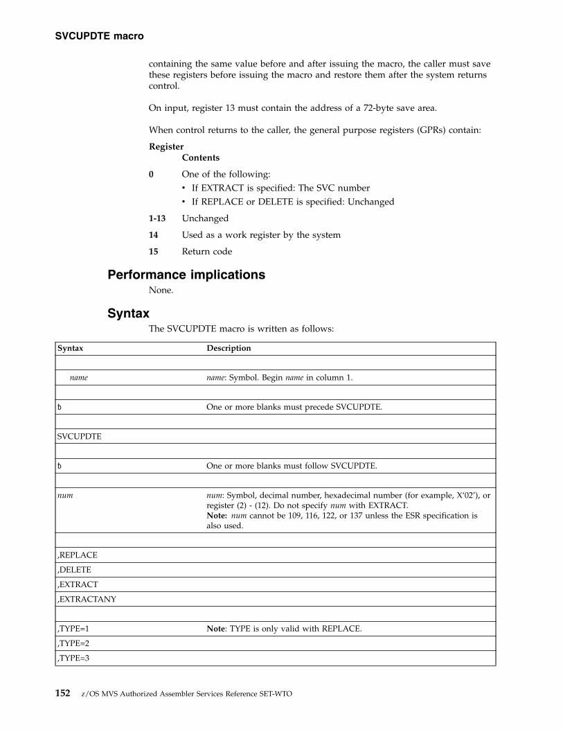
containing the same value before and after issuing the macro, the caller must savethese registers before issuing the macro and restore them after the system returnscontrol.
On input, register 13 must contain the address of a 72-byte save area.
When control returns to the caller, the general purpose registers (GPRs) contain:
RegisterContents
0 One of the following:v If EXTRACT is specified: The SVC numberv If REPLACE or DELETE is specified: Unchanged
1-13 Unchanged
14 Used as a work register by the system
15 Return code
Performance implicationsNone.
SyntaxThe SVCUPDTE macro is written as follows:
Syntax Description
name name: Symbol. Begin name in column 1.
� One or more blanks must precede SVCUPDTE.
SVCUPDTE
� One or more blanks must follow SVCUPDTE.
num num: Symbol, decimal number, hexadecimal number (for example, X‘02’), orregister (2) - (12). Do not specify num with EXTRACT.Note: num cannot be 109, 116, 122, or 137 unless the ESR specification isalso used.
,REPLACE
,DELETE
,EXTRACT
,EXTRACTANY
,TYPE=1 Note: TYPE is only valid with REPLACE.
,TYPE=2
,TYPE=3
SVCUPDTE macro
152 z/OS MVS Authorized Assembler Services Reference SET-WTO

Syntax Description
,TYPE=4
,TYPE=6
,EP=addr addr: A-type address, decimal number, hexadecimal number, or register (2) -(12). addr should be a full 31-bit value with AMODE in bit 0.
,EPNAME=entry-name entry-name: Symbol
Note: EP and EPNAME are not needed with the DELETE option.
,LOCKS=(lname, lname,...) lname: CMS or LOCAL.
Note: LOCKS is invalid with DELETE and EXTRACT, and cannot bespecified with TYPE=6.
,APF=NO Default: APF=NO
,APF=YES Note: APF is only valid with REPLACE.
,AR=NO Default: AR=NO
,AR=YES Note: AR is valid only with REPLACE.
,NPRMPT=NO Default: NPRMPT=NO
,NPRMPT=YES Note: NPRMPT is only valid with REPLACE.
,RELATED=value value: Any valid macro keyword specification.
,ESR=esr esr: decimal number, or register (2) - (12).
,USEECVT=NO Default: USEECVT=NO
,USEECVT=YES
ParametersThe parameters are explained as follows:
numSpecifies the number of the SVC that is being inserted or deleted.
,REPLACE,DELETE
Specifies the function to be performed. REPLACE indicates that an SVC tableentry is to be inserted in the SVC table. This could be a new SVC or areplacement for an existing SVC. DELETE indicates that the specified SVCnumber is to be deleted from the SVC table.
If you issue an SVC instruction with a deleted or undefined SVC number, theprogram abnormally ends with a system completion code of X'Fnn' (nn is theoperand of the SVC instruction, in hexadecimal). However, if you issue an
SVCUPDTE macro
Chapter 14. SVCUPDTE — SVC update 153

SVCUPDTE macro using the DELETE parameter and specify a previouslydeleted SVC number, no abnormal end results.
,EXTRACTIndicates that the user has supplied an EP or EPNAME and wishes to have theSVC number of that routine returned in register 0. The num parameter is notvalid with this option.
,EXTRACTANYIndicates that the user has supplied an EP or EPNAME and wishes to have theSVC or extended SVC number of that routine returned in register 0.
For a non-extended SVCBit 0 of register 0 has a value of 0. Bits 24–31 contain the SVC number.
For an extended SVCBit 0 of register 0 has a value of 1. Bits 16–23 contain the ESR number.Bits 24–31 contain the SVC number.
The num parameter is not valid with this option.
,TYPE=1,TYPE=2,TYPE=3,TYPE=4,TYPE=6
Specifies the SVC type for a REPLACE request. See the topic “ProgrammingConventions for SVC Routines” in z/OS MVS Programming: AuthorizedAssembler Services Guide for information concerning the characteristics andrestrictions for each type of SVC.
,EP=addrSpecifies the entry point address of the SVC routine. The addressing mode ofthe entry point is defined by bit 0 of the entry point address of the SVCroutine. If bit 0=1, the SVC routine will be entered in 31-bit addressing mode;if bit 0=0, the SVC routine will be entered in 24-bit addressing mode.
,EPNAME=entry-nameSpecifies the entry name of the SVC routine. The entry name must be the loadmodule name or alias of a module in LPA or the entry name of a module linkedited into the nucleus. The AMODE of the SVC routine is determined whenthe SVC is link edited.
When entry-name is IGCERROR:v When ESR=esr is not specified, the SVC routine results in a Fxx abend when
SVC xx is issued, where xx matches num.v When ESR=esr is specified, the SVC routine results in abend 16D-8 when
SVC num with routing code esr is issued.
,LOCKS=(lname,lname,...)Specifies the lock(s) required when the SVC routine executes. The lock(s)specified can be CMS or LOCAL. This parameter is valid only with REPLACE.
Note:
1. TYPE=1 must not specify LOCAL.2. TYPE=6 cannot specify any locks.3. TYPE=2, 3, or 4 must specify LOCAL if CMS is specified.
,APF=YES
SVCUPDTE macro
154 z/OS MVS Authorized Assembler Services Reference SET-WTO
,APF=NOSpecifies whether or not the invocation of the SVC is to be restricted toauthorized programs. This parameter is valid only with REPLACE.
,AR=YES,AR=NO
Specifies whether or not the SVC can be issued by a program in access registermode. If you specify NO, a program that issues the SVC while in accessregister mode abends with a completion code of X‘0F8’. This parameter is validonly with REPLACE.
,NPRMPT=YES,NPRMPT=NO
Indicates whether or not the SVC can be preempted for I/O interruptions.
,RELATED=valueProvides information to document the macro by relating the functionperformed to another service or function. The format can be any valid codingvalue that the user chooses.
,ESR=esrSpecifies the extended SVC routing number of an extended SVC. You maysupply a decimal number or a value in register (2) - (12). When you supply anexplicit SVC number, the ESR parameter is only allowed with SVC numbers109, 116, 122, and 137. When you provide the SVC number in a register, theESR specification is ignored if the SVC number is not 109, 116, 122, or 137. Thisparameter is not valid with EXTRACT. When ESR is specified, the TYPEparameter is only used to validate other parameters, because each extendedSVC has a predefined type that cannot be changed.
Note: When using SVC screening with the ESR parameter, the system ignoresthe screening information associated with the ESR number itself (for example,109). The system only uses screening information associated with the routingcode.
,USEECVT=YES,USEECVT=NO
You may use this optional parameter to avoid some system processing.Specifying YES allows the system to locate the SVCUPDTE service with apointer in the ECVT instead of using the NUCLKUP service. You must berunning in AMODE 31 to use this parameter. This parameter also requires theIHAECVT mapping macro.
ABEND codesNone.
Return codesWhen the SVCUPDTE macro returns control to your program, GPR 15 contains ahexadecimal return code.
Table 21. Return Codes for the SVCUPDTE Macro
Return Code Meaning and Action
00 Meaning: The macro completed successfully.
Action: None.
SVCUPDTE macro
Chapter 14. SVCUPDTE — SVC update 155

Table 21. Return Codes for the SVCUPDTE Macro (continued)
Return Code Meaning and Action
04 Meaning: The macro was coded incorrectly. For example, the userrequested REPLACE without specifying an SVC number.
Action: Correct the error in the program that issued the macro. Verify thatthe execute form of the macro correctly references the list form.
08 Meaning: Program error. The DELETE parameter was not specifiedcorrectly.
Action: Correct the error in the program that issued the request. Verify thatthe execute form of the macro correctly references the list form.
0C Meaning: Program error. A REPLACE request contained incorrectinformation. For example, the user specified an SVC type that was not 1through 6, or the specified entry point address was not on a halfwordboundary.
Action: Correct the error in the program that issued the request. Verify thatthe execute form of the macro correctly references the list form.
10 Meaning: Program error. A REPLACE request contained illogicalinformation. For example:
v A type 6 SVC specified a lock.
v Neither an entry point nor an EPNAME was provided for a REPLACErequest.
v Both an entry point and an EPNAME are provided.
v The entry point provided is zero.
v The CMS lock was requested without the LOCAL lock.
Action: Correct the error in the program that issued the request. Verify thatthe execute form of the macro correctly references the list form.
14 Meaning: Program error. The function specified was not REPLACE,DELETE, or EXTRACT.
Action: Verify that the function specified is REPLACE, DELETE, orEXTRACT.
18 Meaning: Program error. The user has attempted to update an extendedSVC router entry in the SVC table (num was specified as 109, 116, 122, or137).
Action: Correct the error in the program that issued the macro. Verify thatthe execute form of the macro correctly references the list form.
1C Meaning: Environmental error. Unable to locate the entry point address foran EPNAME specification.
Action: Verify that all parts of the product or application are currentlyinstalled.
20 Meaning: Program error. An EXTRACT request contains illogicalinformation. For example:
v Neither an entry point address nor an EPNAME is specified.
v Both an entry point address and an EPNAME are specified.
v An SVC number is specified.
v The entry point address specified is zero.
Action: Correct the error in the program that issued the macro. Verify thatthe execute form of the macro correctly references the list form.
24 Meaning: Environmental error. Unable to locate the SVC routine for theEXTRACT request.
Action: Verify that all parts of the product or application are currentlyinstalled.
SVCUPDTE macro
156 z/OS MVS Authorized Assembler Services Reference SET-WTO
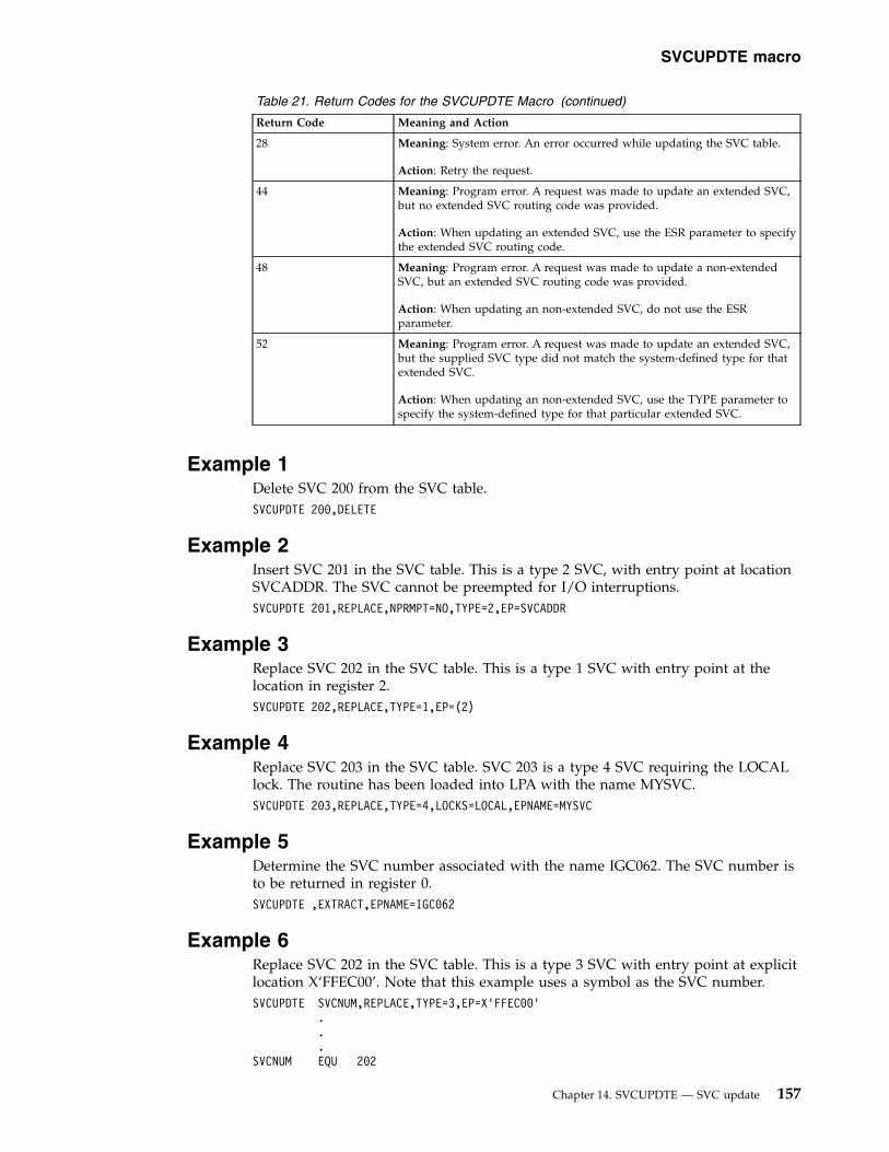
Table 21. Return Codes for the SVCUPDTE Macro (continued)
Return Code Meaning and Action
28 Meaning: System error. An error occurred while updating the SVC table.
Action: Retry the request.
44 Meaning: Program error. A request was made to update an extended SVC,but no extended SVC routing code was provided.
Action: When updating an extended SVC, use the ESR parameter to specifythe extended SVC routing code.
48 Meaning: Program error. A request was made to update a non-extendedSVC, but an extended SVC routing code was provided.
Action: When updating an non-extended SVC, do not use the ESRparameter.
52 Meaning: Program error. A request was made to update an extended SVC,but the supplied SVC type did not match the system-defined type for thatextended SVC.
Action: When updating an non-extended SVC, use the TYPE parameter tospecify the system-defined type for that particular extended SVC.
Example 1Delete SVC 200 from the SVC table.SVCUPDTE 200,DELETE
Example 2Insert SVC 201 in the SVC table. This is a type 2 SVC, with entry point at locationSVCADDR. The SVC cannot be preempted for I/O interruptions.SVCUPDTE 201,REPLACE,NPRMPT=NO,TYPE=2,EP=SVCADDR
Example 3Replace SVC 202 in the SVC table. This is a type 1 SVC with entry point at thelocation in register 2.SVCUPDTE 202,REPLACE,TYPE=1,EP=(2)
Example 4Replace SVC 203 in the SVC table. SVC 203 is a type 4 SVC requiring the LOCALlock. The routine has been loaded into LPA with the name MYSVC.SVCUPDTE 203,REPLACE,TYPE=4,LOCKS=LOCAL,EPNAME=MYSVC
Example 5Determine the SVC number associated with the name IGC062. The SVC number isto be returned in register 0.SVCUPDTE ,EXTRACT,EPNAME=IGC062
Example 6Replace SVC 202 in the SVC table. This is a type 3 SVC with entry point at explicitlocation X‘FFEC00’. Note that this example uses a symbol as the SVC number.SVCUPDTE SVCNUM,REPLACE,TYPE=3,EP=X’FFEC00’
.
.
.SVCNUM EQU 202
SVCUPDTE macro
Chapter 14. SVCUPDTE — SVC update 157
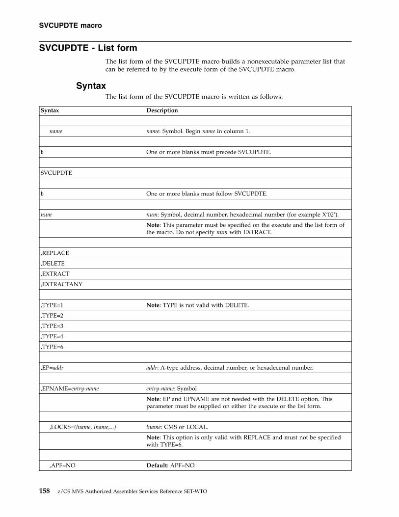
SVCUPDTE - List formThe list form of the SVCUPDTE macro builds a nonexecutable parameter list thatcan be referred to by the execute form of the SVCUPDTE macro.
SyntaxThe list form of the SVCUPDTE macro is written as follows:
Syntax Description
name name: Symbol. Begin name in column 1.
� One or more blanks must precede SVCUPDTE.
SVCUPDTE
� One or more blanks must follow SVCUPDTE.
num num: Symbol, decimal number, hexadecimal number (for example X‘02’).
Note: This parameter must be specified on the execute and the list form ofthe macro. Do not specify num with EXTRACT.
,REPLACE
,DELETE
,EXTRACT
,EXTRACTANY
,TYPE=1 Note: TYPE is not valid with DELETE.
,TYPE=2
,TYPE=3
,TYPE=4
,TYPE=6
,EP=addr addr: A-type address, decimal number, or hexadecimal number.
,EPNAME=entry-name entry-name: Symbol
Note: EP and EPNAME are not needed with the DELETE option. Thisparameter must be supplied on either the execute or the list form.
,LOCKS=(lname, lname,...) lname: CMS or LOCAL.
Note: This option is only valid with REPLACE and must not be specifiedwith TYPE=6.
,APF=NO Default: APF=NO
SVCUPDTE macro
158 z/OS MVS Authorized Assembler Services Reference SET-WTO

Syntax Description
,APF=YES Note: APF is only valid with REPLACE.
,AR=NO Default: AR=NO
,AR=YES Note: AR is valid only with REPLACE.
,NPRMPT=NO Default: NPRMPT=NO
,NPRMPT=YES Note: NPRMPT is only valid with REPLACE.
,RELATED=value value: Any valid macro keyword specification.
,ESR=esr esr: decimal number, or register (2) - (12).
,MF=L
ParametersThe parameters are explained under the standard form of the SVCUPDTE macrowith the following exception:
,MF=LSpecifies the list form of the SVCUPDTE macro.
Example 1Use the list form of the macro to replace SVC 202 in the SVC table. It is a type 2SVC with entry point at location SVCADDR. The SVC routine needs the local lock.SVCUPDTE 202,REPLACE,TYPE=2,LOCKS=LOCAL,MF=L,EP=SVCADDR
Example 2Use the list form of the macro to replace SVC 201 in the SVC table. The routine is atype 2 SVC.SVCUPDTE 201,REPLACE,TYPE=2,MF=L
SVCUPDTE - Execute form
SyntaxThe execute form of the SVCUPDTE macro is written as follows:
Syntax Description
name name: Symbol. Begin name in column 1.
� One or more blanks must precede SVCUPDTE.
SVCUPDTE
SVCUPDTE macro
Chapter 14. SVCUPDTE — SVC update 159

Syntax Description
� One or more blanks must follow SVCUPDTE.
num num: Register (2) - (12).
Note: This parameter must be supplied on either the execute or the list formof the macro with REPLACE or DELETE, and it must not be specified withEXTRACT.
,EP=addr addr: Register (2) - (12).
Note: This parameter must be supplied on either the execute or the list formof the macro. This parameter is not needed with the DELETE option.
,EPNAME=entry-name entry-name: Symbol
Note: EP and EPNAME are not needed with the DELETE option. Thisparameter must be supplied on either the execute or the list form.
,RELATED=value value: Any valid macro keyword specification.
,USEECVT=NO Default: USEECVT=NO
,USEECVT=YES
,MF=(E,addr) addr: RX-type address or register (2) - (12).
ParametersThe parameters are explained under the standard form of the SVCUPDTE macrowith the following exception:
,MF=(E,addr)Specifies the execute form of the SVCUPDTE macro.
ExampleUse the execute form of the SVCUPDTE macro to perform the function specifiedby the parameter list whose address is given in register 2.SVCUPDTE MF=(E,(2))
SVCUPDTE macro
160 z/OS MVS Authorized Assembler Services Reference SET-WTO

Chapter 15. SWAREQ — Invoke SWA manager in locate mode
DescriptionThe SWAREQ macro has no standard form. It only has a list, an execute, and amodify form. The MF parameter, which indicates the form of the macro, isrequired.
When you invoke this macro in execute form, it uses the two parameters, FCODEand EPA, to modify the parameter list, which is at the location you specify by theaddr value in the MF=(E,addr) parameter. After ensuring the validity of theparameters, it invokes the SWA manager in locate mode. The SWA managerobtains its input from the parameter list, and performs the function associated withthe specified FCODE. If you do not specify any parameters, the macro assumes theparameter list already exists, and it simply invokes the SWA manager.
The modify form of SWAREQ is functionally the same as the execute form, exceptthat the macro only modifies the parameter list without invoking the SWAmanager. The list form of SWAREQ generates the parameter list that is modifiedby the other two forms of the macro, and it does not invoke the SWA manager.
EnvironmentThe requirements of callers when UNAUTH=NO (the default) is specified are:
Environmental factor RequirementMinimum authorization: Supervisor state and any PSW key.Dispatchable unit mode: Task.Cross memory mode: PASN=HASN=SASN.AMODE: 24- or 31-bit.ASC mode: Primary.Interrupt status: Enabled for I/O and external interrupts.Locks: No locks may be held.Control parameters: Must be in the caller's primary address space.
The requirements of callers when UNAUTH=YES is specified are:
Environmental factor RequirementMinimum authorization: Problem state and any PSW key.Dispatchable unit mode: Task or SRB. For SRB mode, see “Programming
requirements” on page 162 for details.Cross memory mode: PASN=HASN=SASN, or for cross-memory mode, see
“Programming requirements” on page 162 for details.AMODE: 31-bit.ASC mode: Primary.Interrupt status: Enabled for I/O and external interrupts.Locks: The local lock or CMS lock may be held but are not
required.Control parameters: Must be in the caller's primary address space.
© Copyright IBM Corp. 1988, 2017 161

Programming requirementsThe caller must include the following mapping macros:v IEFZB505
When UNAUTH=YES is specified, invoke the IEFZB505 macro specifyingLOCEPAX=YES, which generates a longer, 28-byte EPA.
v IEFJESCTv CVTv IEFQMIDS
When in cross-memory mode or SRB mode, you must pass the queue managerparameter area (QMPA) address to SWAREQ. In this case, obtain the QMPAaddress from the active JSCB for the primary address space and place this addressin the EPAL that SWAREQ refers to by its input parameter. Note that wheninvoking SWAREQ in cross-memory mode, you may only obtain SWA informationassociated with the primary address space.
RestrictionsNone.
Input register informationOn input to the macro, register 13 must contain the address of a standard 18-wordsave area.
Output register informationWhen control returns to the caller, the general purpose registers (GPRs) contain:
RegisterContents
0 When control returns from SWAREQ, used as a work register by thesystem.
When control does not return from SWAREQ, the address of a 16-byte areacontaining:
Bytes 1-4Address of the QMPA
Bytes 5-12Not an intended programming interface; record this informationand provide it to the appropriate IBM support personnel.
Bytes 13-16Address of the failing EPA
1 When control returns from SWAREQ, used as a work register by thesystem.
When control does not return from SWAREQ, abend code 0B0.
2-12 Unchanged
13 If AMODE 31, then high bit will be cleared. If AMODE 24, then high bytewill be cleared.
14 Unchanged
15 Return code
SWAREQ macro
162 z/OS MVS Authorized Assembler Services Reference SET-WTO

Performance implicationsNone.
ABEND codesThe caller of the SWAREQ macro might receive abend code X’0B0’ with one of thefollowing reason codes:v X’04’
v X’08’
v X’0C’
v X’1C’
v X’20’
v X’24’
v X’28’
v X’34’
See z/OS MVS System Codes for explanations and responses for these codes.
Return and reason codesThe hexadecimal return code is in register 15. When you specify UNAUTH=YES,the return codes have the following meanings:
Table 22. Return codes for the SWAREQ macro with UNAUTH=YES
Return Code Meaning
0 The SWAREQ service was successful.
8 The SVA in the SWA prefix was not valid.
24 The SVA does not correspond to any virtual address.
28 The pointer to the EPAL was not valid.
When you do not specify UNAUTH=YES, the return codes have the followingmeanings:
Table 23. Return codes for the SWAREQ macro
Return Code Meaning
0 The SWAREQ service was successful.
8 The SVA in the SWA prefix was not valid.
0C You attempted to read a block that was not yet written.
10 The length for a SWA block was not valid.
1C The block id was not valid.
20 The block pointer was not valid.
24 The SVA does not correspond to any virtual address.
SWAREQ - List form
SyntaxThe list form of the SWAREQ macro is written as follows:
Syntax Description
SWAREQ macro
Chapter 15. SWAREQ — Invoke SWA manager in locate mode 163

Syntax Description
name name: Symbol. Begin name in column 1.
� One or more blanks must precede SWAREQ.
SWAREQ
� One or more blanks must follow SWAREQ.
,FCODE=fncde fncde: Function code
,EPA=addr addr: Address of the pointer to the EPA.
In the list form, this address may only be specified symbolically.
,MF=L
ParametersThe parameters are explained as follows:
,FCODE=fncdeSpecifies the function code for the locate mode request. Valid codes are:
RL Read/Locate
WL Write/Locate
For more information about the meaning of each code, see z/OS MVSProgramming: Authorized Assembler Services Guide.
,EPA=addrSpecifies the address of the pointer to the extended parameter area (EPA). Donot specify the EPA itself on the EPA parameter.
,MF=LSpecifies the list form of the SWAREQ macro.
SWAREQ - Execute form
SyntaxThe execute form of the SWAREQ macro is written as follows:
Syntax Description
name name: Symbol. Begin name in column 1.
⌂ One or more blanks must precede SWAREQ.
SWAREQ
SWAREQ macro
164 z/OS MVS Authorized Assembler Services Reference SET-WTO
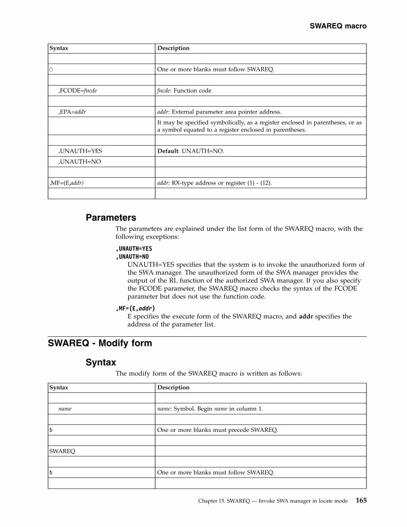
Syntax Description
⌂ One or more blanks must follow SWAREQ.
,FCODE=fncde fncde: Function code
,EPA=addr addr: External parameter area pointer address.
It may be specified symbolically, as a register enclosed in parentheses, or asa symbol equated to a register enclosed in parentheses.
,UNAUTH=YES Default: UNAUTH=NO.
,UNAUTH=NO
,MF=(E,addr) addr: RX-type address or register (1) - (12).
ParametersThe parameters are explained under the list form of the SWAREQ macro, with thefollowing exceptions:
,UNAUTH=YES,UNAUTH=NO
UNAUTH=YES specifies that the system is to invoke the unauthorized form ofthe SWA manager. The unauthorized form of the SWA manager provides theoutput of the RL function of the authorized SWA manager. If you also specifythe FCODE parameter, the SWAREQ macro checks the syntax of the FCODEparameter but does not use the function code.
,MF=(E,addr)E specifies the execute form of the SWAREQ macro, and addr specifies theaddress of the parameter list.
SWAREQ - Modify form
SyntaxThe modify form of the SWAREQ macro is written as follows:
Syntax Description
name name: Symbol. Begin name in column 1.
� One or more blanks must precede SWAREQ.
SWAREQ
� One or more blanks must follow SWAREQ.
SWAREQ macro
Chapter 15. SWAREQ — Invoke SWA manager in locate mode 165

Syntax Description
,FCODE=fncde fncde: Function code
,EPA=addr addr: External parameter area pointer address.
It may be specified symbolically, as a register enclosed in parentheses, or asa symbol equated to a register enclosed in parentheses.
,MF=(M,addr) addr: RX-type address or register (1) - (12).
ParametersThe parameters are explained under the list form of the SWAREQ macro, with thefollowing exceptions:
,MF=(M,addr)M specifies the modify form of the SWAREQ macro, and addr specifies theaddress of the parameter list.
SWAREQ macro
166 z/OS MVS Authorized Assembler Services Reference SET-WTO
Chapter 16. SWBTUREQ — Call SJF SWBTU processingservices
DescriptionSWBTUREQ requests services for processing scheduler work block text units(SWBTUs). The RETRIEVE service can be requested on the SWBTUREQ macro.RETRIEVE obtains text unit information from SWBTUs for a specified set of keysand places the information in the output area defined by the caller.
An SWBTU is made up of JCL statement or dynamically created JCL informationin contiguous text unit format. More than one SWBTU may be used to represent asingle JCL statement.
Examples of the use of SWBTUREQ RETRIEVE are the JES sysout separator pageinstallation exits. See the HASX01B member of SYS1.SHASSAMP for a sample exit.
For the RETRIEVE service, there are three calls that you can make:v A call to determine the local working storage size needed for the servicev A call to determine the output area size needed to accommodate all the matched
text unitsv A call to obtain the text units that match the requested keys.
EnvironmentThe requirements for the caller are:
Environmental factor RequirementMinimum authorization: Problem state, and any PSW key. For SWBTUREQ
RETRIEVE, the caller must have a PSW key that matches thekey of the caller's storage.
Dispatchable unit mode: TaskCross memory mode: PASN=HASN=SASNAMODE: 24- or 31-bitASC mode: PrimaryInterrupt status: Enabled for I/O and external interruptsLocks: No locks heldControl parameters: Must be in the primary address space
Programming requirementsThe caller must set up recovery for SWBTUREQ RETRIEVE. The caller mustinclude the CVT and IEFJESCT mapping macros. IEFSJTRP maps the storage forthe required RETRIEVE service parameter list. “SWBTUREQ RETRIEVE inputparameters” on page 169 describes the parameter list's input fields. “SWBTUREQRETRIEVE output” on page 170 describes the fields that contain output on returnfrom the SWBTUREQ RETRIEVE service.
The caller is responsible for supplying all storage for SWBTUREQ RETRIEVEprocessing. You can use SWBTUREQ RETRIEVE with different combinations ofparameters to determine the local working storage size needed, and to determineand obtain the output area size needed for a particular request. A thirdcombination of parameters allows you to invoke SWBTUREQ RETRIEVE to obtain
© Copyright IBM Corp. 1988, 2017 167

text unit information. Table 24 on page 169 lists the required combination ofparameters to use based on the type of service call you are making.
RestrictionsNone.
Input register informationOn input to the SWBTUREQ macro, the caller must insure that general purposeregister (GPR) 13 points to a standard, 72-byte save area.
Output register informationWhen control returns to the caller, the general purpose registers (GPRs) contain:
RegisterContents
0 If GPR 15 contains a zero, GPR 0 is used as a work register by the system.If GPR 15 contains return code 12, GPR 0 contains a reason code;otherwise, GPR 0 contains zero.
1 Used as a work register by the system
2-13 Unchanged
14 Used as a work register by the system
15 Return code
Performance implicationsNone.
SyntaxThe standard form of the SWBTUREQ macro is written as follows:
Syntax Description
name name: Symbol. Begin name in column 1.
⌂ One or more blanks must precede SWBTUREQ
SWBTUREQ
⌂ One or more blanks must follow SWBTUREQ
REQUEST=service service: Service name
,PARM=addr addr: RX-type address, or registers (2) - (12). Register 1 is the default.
ParametersThe parameters are explained as follows:
SWBTUREQ macro
168 z/OS MVS Authorized Assembler Services Reference SET-WTO
REQUEST=serviceSpecifies the SJF SWBTU service to be called. RETRIEVE is the valid servicename.
,PARM=addrSpecifies the address of the parameter list for the service requested. Theparameter list for the RETRIEVE service is IEFSJTRP. “SWBTUREQ RETRIEVEinput parameters” lists the parameter fields you must initialize.
SWBTUREQ RETRIEVE serviceUse RETRIEVE to obtain text unit information for a specified set of JCL or outputdescriptor keys. The retrieved information is placed in a caller-defined output area.
Table 24. Parameter Combinations for SWBTUREQ RETRIEVE Functions
Function Required Parameters
Obtain localworking storagesize
SJTRID, SJTRVERS, SJTRLEN, SJTRSTOR, SJTRSTSZ, SJTRAREA, andSJTRSIZE. SJTRSTOR, SJTRSTSZ, SJTRAREA, and SJTRSIZE should bezero on this invocation.
Obtain outputarea size
SJTRID, SJTRVERS, SJTRLEN, SJTRSTOR, SJTRSTSZ, SJTRSWBN,SJTRSWBA, SJTRKIDN, SJTRKIDL. Fill in SJTRSTOR and SJTRSTSZwith the values returned when you invoked the macro to determine thelocal working storage size. SJTRAREA and SJTRSIZE should be zero onthis invocation.
Retrieverequested keys
SJTRID, SJTRVERS, SJTRLEN, SJTRSTOR, SJTRSTSZ, SJTRSWBN,SJTRSWBA, SJTRKIDN, SJTRKIDL. Fill in SJTRSTOR, SJTRSTSZ,SJTRAREA, and SJTRSIZE with the values returned when you invokedthe macro to determine the local working storage size and the outputbuffer size.
SWBTUREQ RETRIEVE input parametersFor each SWBTUREQ invocation, you need to initialize certain fields of parameterlist IEFSJTRP. Figure 4 on page 171 illustrates some of the parameter fields andtheir relationships to other fields. The list below describes the valid valueassignments for all input parameters in IEFSJTRP.
SJTRIDThe identifier ‘SJTR’ of the SWBTUREQ RETRIEVE parameter list. Assign thesymbolic equate SJTRCID to this field.
SJTRVERSThe current version number of the SWBTUREQ RETRIEVE service. Assign thesymbolic equate SJTRCVER to this field.
SJTRLENThe length of the SWBTUREQ RETRIEVE parameter list (IEFSJTRP). Assign thesymbolic equate SJTRLGTH to this field.
SJTRSTORThe local working storage pointer or zero.
SJTRSTSZThe size of the local working storage area required by the service.
SJTRSWBNThe number of SWBTUs in the SWBTU address list table. The table is mappedby SJTRSBTL.
SWBTUREQ macro
Chapter 16. SWBTUREQ — Call SJF SWBTU processing services 169

SJTRSWBAThe address of the SWBTU address list table from which text units areretrieved. The address list is mapped by SJTRSBTL.
SJTRAREAThe address of the text unit output area.
SJTRSIZEThe size of the text unit output area.
SJTRKIDNThe number of entries in the key list. The key list is mapped by SJTRKEYL.
SJTRKIDLThe address of the list of keys that are to be retrieved. The key list is mappedby SJTRKEYL.
SJTRSBTLSWBTU address list from which text units are returned. The list contains oneentry per SWBTU. Parameter SJTRSWBN specifies the number of entries in thelist; SJTRSWBA specifies the address of the list. More than one SWBTU may beused to represent a single JCL statement.
SJTRSTUPAn SWBTU address entry.
SJTRKEYLThe requested list of keys to be retrieved. Parameter SJTRKIDN specifies thenumber of entries in the list; SJTRKIDL specifies the address of this list.
SJTRKYIDThe key to be used for the retrieve. If you are using the RETRIEVE serviceto obtain information about output descriptors, the key values for theattributes are defined in mapping macro IEFDOKEY. See z/OS MVS DataAreas in the z/OS Internet library (www.ibm.com/systems/z/os/zos/library/bkserv) for the mapping provided by IEFDOKEY. z/OS MVSProgramming: Authorized Assembler Services Guide lists the dynamic outputkeys and their JCL equivalents.
SWBTUREQ RETRIEVE outputThese parameters are returned with values on completion of RETRIEVE serviceprocessing.
SJTRREASThe reason code returned. The reason codes are defined in “Return and reasoncodes” on page 171.
SJTRWKSZThe local working storage size required by the SWBTUREQ service.
SJTRTULNThe size of the area needed to contain all matched requested text units.
SJTRERRPThis field contains a zero unless a parameter list error (key list or SWBTUaddress entry error) occurs. In the case of a key list error (return code 8 with areason code of 65), the address of the key list entry in error appears in thefield. In the case of a SWBTU address entry error (return code 8 with a reasoncode of 19 or 28), the address of the SWBTU address entry in error appears inthe field.
SWBTUREQ macro
170 z/OS MVS Authorized Assembler Services Reference SET-WTO

SJTRAREAThe address of the text unit output area. The text unit output area contains thematched text unit strings organized by key in the order they were requested.Matched text unit strings are contiguous in the text unit output area. For themapping of each text unit see the IEFDOTUM mapping macro in z/OS MVSData Areas in the z/OS Internet library (www.ibm.com/systems/z/os/zos/library/bkserv).
SJTRKEYLThe requested key list. Parameter SJTRKIDN specifies the number of entries inthe list; SJTRKIDL specifies the address of this list.
SJTRTPADThe address of a text unit for this key in the output area. Values arereturned in this field only if the key and text unit match. If the address isnot found, this field is zero.
ABEND codesNone.
Return and reason codesReturn codes appear in register 15. If you receive return code 12, the reason codeappears in register 0. If you receive return codes 0, 4, or 8, the reason code appearsin output field SJTRREAS. Return and reason codes are defined in macroIEFSJTRC. The hexadecimal return and reason codes from the SWBTUREQRETRIEVE service are as follows:
SJTRSTORSJTRSTSZ
SJTRSWBNSJTRSWBA
SJTRAREASJTRSIZE
SJTRKIDLSJTRKIDN
IEFSJTRP
The SWBUT addresslist. Each entry inthis table addressesan input SWBTU.
@ input SWBTU
On input, containsa list of requestedkeys (SJTRKYID).
On output:
SJTRTPAD
SJTRKEYL
Local workingstorage area
Working Storage
On return fromSWBTUREQ RETRIEVEprocessing, it containsmatched text units.
Text Unit Output Area
Contains inputtext units
Input SWBTU
SJTRSBTL
on output
Figure 4. Relationship of Data and Work Areas Referenced in IEFSJTRP
SWBTUREQ macro
Chapter 16. SWBTUREQ — Call SJF SWBTU processing services 171

Table 25. Return and Reason Codes for SWBTUREQ RETRIEVE
Return Code Reason Code Meaning and Action
00 None Meaning: RETRIEVE processing completedsuccessfully. At least one text unit and key matchwas found. For any unmatched text units, thecorresponding SJTRTPAD values are zero.
Action: None.
04 None Meaning: Either the caller did not provideenough storage for the service or none of therequested items was found. This is the expectedreturn code if you issue the RETRIEVE request toobtain the working storage size or output areasize.
004 Meaning: RETRIEVE requires more localworking storage. The size of the local workingstorage, as specified in input parameterSJTRSTSZ, is not large enough for the service.The amount of local working storage neededappears in output parameter SJTRWKSZ.
Action: Repeat the request and supply theamount of storage returned in SJTRWKSZ inSJTRSTSZ.
008 Meaning: RETRIEVE requires more text unitoutput area storage. The size needed for theoutput storage area appears in output parameterSJTRTULN.
Action: Repeat the request and supply theamount of storage returned in SJTRTULN inSJTRAREA.
064 Meaning: Successful completion. None of thekeys in the input key list were found in theSWBTUs. All corresponding SJTRTPAD valuesare zero. There are no returned text units in theoutput area.
Action: None required.
08 None Meaning: The parameter list is not valid.
015 Meaning: The parameter length specified inSJTRLEN is not valid for the specified version.
016 Meaning: The version number specified is notcorrect for this service.
018 Meaning: The caller must provide at least oneSWBTU. Input parameter SJTRSWBN must begreater than zero, and SJTRSWBA must referencethe SWBTU address list.
Action: Set SJTRSWBN to a value greater thanzero; set SJTRSWBA to the address of the SWBTVaddress list.
019 Meaning: The specified SWBTU is not valid.Either one of the entries is zero, or the SWBTUaddress entry is not valid. Output parameterSJTRERRP contains the address of the SWBTUaddress entry.
Action: Specify a valid SWBTU referenced by theSWBTU address is in SJTRERRP.
SWBTUREQ macro
172 z/OS MVS Authorized Assembler Services Reference SET-WTO

Table 25. Return and Reason Codes for SWBTUREQ RETRIEVE (continued)
Return Code Reason Code Meaning and Action
01A Meaning: Program error. The text length shownin the DOCNTLEN field in the IEFDOTUMmapping macro is not valid. SWBTUREQRETRIEVE processing stops. One possible causeof the problem is a storage overlay.
Action: If your program has overlaid storage,correct the error and rerun the program.Otherwise, contact the appropriate IBM supportpersonnel.
028 Meaning: Either all of the verbs for the SWBTUsor all of the labels for the SWBTUs do not match.Output parameter SJTRERRP contains theaddress of the SWBTU address entry where theinconsistency was found.
Action: Correct the SWBTU in the SWBTUaddress table entry whose address is inSJTRERRP.
029 Meaning: The output area size, defined by thecombination of the input parameters SJTRAREAand SJTRSIZE, is not valid. One of theparameters is zero and the other is not zero.
Action: Set SJTRAREA and SJTRSIZE to valuesgreater than 0. (See “SWBTUREQ RETRIEVEinput parameters” on page 169.)
065 Meaning: The key entry is not valid. Inputparameter SJTRKYID is zero. Output parameterSJTRERRP contains the address of the error keyentry, SJTRKYID.
Action: Correct the key in error (the key pointedto by SJTRKYID).
066 Meaning: At least one key must be requested.Input parameter SJTRKIDN must be greater thanzero and SJTRKIDL must reference the key entrylist.
Action: Set SJTRKIDN and SJTRKIDL to valuesgreater than zero. (See input parameterdescription.)
0C None Meaning: A severe parameter list error occurred.The reason code appears in register 0.
014 Meaning: An incorrect parameter ID wasspecified. SJTRID is not ‘SJTR’.
Action: See “SWBTUREQ RETRIEVE inputparameters” on page 169 for SJTRID.
015 Meaning: An incorrect parameter length wasspecified. SJTRLEN is not at least as large as thecommon parameter list size, 36 bytes.
Action: See “SWBTUREQ RETRIEVE inputparameters” on page 169 for SJTRLEN.
016 Meaning: The version number is not correct.SJTRVERS is less than one.
Action: See “SWBTUREQ RETRIEVE inputparameters” on page 169 for SJTRVERS.
SWBTUREQ macro
Chapter 16. SWBTUREQ — Call SJF SWBTU processing services 173

Table 25. Return and Reason Codes for SWBTUREQ RETRIEVE (continued)
Return Code Reason Code Meaning and Action
017 Meaning: The service specified by SWBTUREQREQUEST=service, is not known.
Action: Specify a valid request for 'service'.
14 None Meaning: SJF encountered a condition thatwould have caused an abend. If processing hadcontinued, an abend would have occurred.
18 None Meaning: The service routines for SWBTUREQare not available.
ExampleInvoke the SWBTUREQ RETRIEVE service to obtain text unit information for threeoutput descriptor attributes (title, name, and room). Represent the outputdescriptor with SWBTU1 and SWBTU2. Use register 6 to contain the address ofSWBTU1, and register 7 to contain the address of SWBTU2. Use AREA to definethe text unit output area. Define the service's local working storage in LCLSTOR.Establish an ESTAE for a recovery environment.
On return, register 15 contains return code 0, register 0 contains reason code 0, andSJTRREAS contains reason code 0. The output areas from the service contain thefollowing information:v SJTRAREA contains two contiguous text units that were in the SWBTUs and
were requested in the key list.v SJTRWKSZ contains the size of local working storage required for the
SWBTUREQ RETRIEVE service.v SJTRTULN contains the size of the area used to return the two matched text
units.v SJTRKEYL contains unchanged SJTRKYIDs.
– SJTRTPAD contains the pointers for the matched text units and zero forunmatched text units. For this example, SJTRTPAD's first entry points to thefirst text unit returned in the text unit output area. The second entry containszero, and the third entry points to the second text unit returned in the textunit output area.
************************************************************************ ** Fill in 3 requested keys in the key list, SJTRKEYL. ** *************************************************************************
XC KEYLIST,KEYLIST Initialize KEYLIST areaLA R2,KEYLIST Point to start of key listUSING SJTRKEYL,R2 Establish addressability
*MVC SJTRKYID+0*SJTRKLEN,=Y(DOTITLE) Title KeyMVC SJTRKYID+1*SJTRKLEN,=Y(DONAME) Name KeyMVC SJTRKYID+2*SJTRKLEN,=Y(DOROOM) Room Key
************************************************************************* ** Fill in 2 SWBTU pointers in SWBTU address list, SJTRSBTL. ** *************************************************************************
XC SWBTULST,SWBTULST Initialize SWBTU pointer list area*
SWBTUREQ macro
174 z/OS MVS Authorized Assembler Services Reference SET-WTO

LA R3,SWBTULST Point to start of SWBTU pointer listUSING SJTRSBTL,R3 Establish addressability
*ST R6,SJTRSTUP Set address of first SWBTU in 1st
* entry of SWBTU address listLA R3,SJTRSLEN(,R3) Point to second entry in SWBTUST R7,SJTRSTUP Set address of second SWBTU in 2nd
* entry of SWBTU address list************************************************************************* ** Fill in the SWBTUREQ RETRIEVE parameter list, IEFSJTRP. ** *************************************************************************
XC SJTRP(SJTRLGTH),SJTRP Clear the parameter listMVC SJTRID,=A(SJTRCID) Parameter list IDMVI SJTRVERS,SJTRCVER Parameter list versionLA R4,SJTRLGTH Get parameter list lengthSTH R4,SJTRLEN Set parameter list length
*LA R4,LCLSTOR Get local working storage addressST R4,SJTRSTOR Set local working storage addressLA R4,STORLGTH Get local working storage sizeSTH R4,SJTRSTSZ Set local working storage size
*LA R4,AREA Get text unit output area addressST R4,SJTRAREA Set text unit output area addressLA R4,AREALGTH Get text unit output area sizeSTH R4,SJTRSIZE Set text unit output area size
*ST R2,SJTRKIDL Set key list addressLA R4,KEYNUM Get number of requested keysSTH R4,SJTRKIDN Set number of request keys
*LA R3,SWBTULST Point to start of SWBTU pointer listST R3,SJTRSWBA Set address of SWBTU address listLA R4,SWBTUNUM Get number of SWBTUsSTH R4,SJTRSWBN Set number of SWBTUs
************************************************************************* ** Set up Register 1 to point to a word of storage that ** contains the address of the parameter list, IEFSJTRP. ** *************************************************************************
LA R4,SJTRP Address ofST R4,SJTRPPTR the SWBTUREQ RETRIEVELA R1,SJTRPPTR parameter list
************************************************************************* ** Invoke the SWBTUREQ macro to retrieve the matched text units ** for items in the requested key list. ** *************************************************************************
SWBTUREQ REQUEST=RETRIEVE Issue the SJF macro************************************************************************* ** Check for a zero return code. ** *************************************************************************
LTR R15,R15 Check service return code
SWBTUREQ macro
Chapter 16. SWBTUREQ — Call SJF SWBTU processing services 175

BNZ NODATA Go to nonzero return processing** Code to process zero return code from SWBTUREQ ...* .* .* .*NODATA DS 0H Label used for branch when SWBTUREQ* service returns with a nonzero* return code.** Code to process nonzero return code from SWBTUREQ...* .* .* .************************************************************************* ** Storage definitions ** *************************************************************************
IEFSJTRP DSECT=NO SWBTUREQ Retrieve parameter list*SJTRPPTR DS A Field used to contain SJTRP address*KEYLIST DS CL24 Area mapped by SJTRKEYL:* enough storage for 3 entries*SWBTULST DS CL16 Area mapped by SJTRSBTL:* enough storage for 2 entries*AREA DS CL600 Area used by SWBTUREQ service to move* matched text units for output.* 600 bytes is large enough and was* chosen at random.AREALGTH EQU *-AREA Size of AREA*LCLSTOR DS CL1000 Area used by SWBTUREQ service as* local working storage.STORLGTH EQU *-LCLSTOR Size of LCLSTOR************************************************************************* ** Equates and Constants ** *************************************************************************R0 EQU 0 Register 0R1 EQU 1 Register 1R2 EQU 2 Register 2R3 EQU 3 Register 3R4 EQU 4 Register 4R15 EQU 15 Register 15*SWBTUNUM EQU 2 Indicates number of SWBTUsKEYNUM EQU 3 Indicates number of requested keys*
IEFDOKEY Dynamic Output keysCVT DSECT=YES CVT mapping macroIEFJESCT IEFJESCT mapping macro
SWBTUREQ macro
176 z/OS MVS Authorized Assembler Services Reference SET-WTO

Chapter 17. SYNCH and SYNCHX — Take a synchronous exitto a processing program
DescriptionThe SYNCH macro takes a synchronous exit to a processing program. After theprocessing program has been executed, the program that issued the SYNCH macroregains control. The SYNCH macro is also described in z/OS MVS Programming:Assembler Services Reference ABE-HSP with the exception of the KEYADDR, STATE,KEYMASK, and XMENV parameters. These parameters are restricted to programsin supervisor state, key 0-7, or APF-authorized.
The SYNCH macro is intended for use by primary mode programs only. If yourprogram runs in access register (AR) mode, use SYNCHX, which provides thesame function as SYNCH. Descriptions of SYNCH and SYNCHX are:v The standard form of the SYNCH macro, which includes general information
about the SYNCH and SYNCHX macros and some specific information aboutthe SYNCH macro. The syntax of the SYNCH macro is presented, and allSYNCH parameters are explained.
v The standard form of the SYNCHX macro, which presents information specificto the SYNCHX macro and callers in AR mode.
v The list form of the SYNCH and SYNCHX macros.v The execute form of the SYNCH and SYNCHX macros.
If the caller is in AR mode, the system passes the following values, unchanged, tothe processing program:v ARs 0-13v Bits 16 and 17 of the current PSW indicating the ASC mode (primary or AR
mode, where primary=secondary=home)v Extended authorization index (EAX)
Parameters for SYNCH and SYNCHX must be in the caller's primary addressspace. Callers in AR mode must initialize AR 1 to zero before issuing SYNCHX.
Note: The SYNCH and SYNCHX macros have the same environmentspecifications, register information, programming requirements, restrictions andlimitations, performance implications, and return and reason codes describedbelow, except where noted in the explanation for SYNCHX.
EnvironmentThe requirements for the caller are:
Environmental factor RequirementMinimum authorization: Problem state and any PSW key.Dispatchable unit mode: TaskCross memory mode: PASN=HASN=SASNAMODE: 24- or 31-bit for SYNCH; 24- or 31- or 64-bit for SYNCHX.ASC mode: PrimaryInterrupt Status: Enabled for I/O and external interruptsLocks: No locks held
© Copyright IBM Corp. 1988, 2017 177

Environmental factor RequirementControl parameters: Must be in the primary address space.
Programming requirementsNone.
RestrictionsNone.
Register informationAfter the caller issues the macro, the system might use some registers as workregisters or might change the contents of some registers. When the system returnscontrol to the caller, the contents of these registers are not the same as they werebefore the macro was issued. Therefore, if the caller depends on these registerscontaining the same value before and after issuing the macro, the caller must savethese registers before issuing the macro and restore them after the system returnscontrol.
When control returns to the caller, the GPRs contain:
RegisterContents
0-1 Values the processing program placed there before it returned to the caller
2-13 If RESTORE=YES, unchanged
If RESTORE=NO, values the processing program placed there before itreturned to the caller
14 Used as a work register by the system
15 Value the processing program placed there before it returned to the caller
SyntaxThe SYNCH macro is written as follows:
Syntax Description
name name: Symbol. Begin name in column 1.
� One or more blanks must precede SYNCH.
SYNCH
� One or more blanks must follow SYNCH.
entry point addr entry point addr: RX-type address, or register (2) - (12) or (15).
,RESTORE=NO Default: RESTORE=NO
,RESTORE=YES
SYNCH and SYNCHX macros
178 z/OS MVS Authorized Assembler Services Reference SET-WTO

Syntax Description
,KEYADDR=addr addr: RS-type address, or register (2) - (12).
,KEYADDR=NOKEYADDR Default: KEYADDR=NOKEYADDR
(The key in the TCB is used.)
,STATE=PROB Default: STATE=PROB
,STATE=SUPV
,KEYMASK=addr addr: RX-type address, or register (0) - (12).
,XMENV=addr addr: RX-type address or register (0) - (12).
,AMODE=24 Default: AMODE=CALLER
,AMODE=31 Note: AMODE=DEFINED can only be specified if the entry point isprovided in a register.
,AMODE=DEFINED
,AMODE=CALLER
,RMODE64=NO Default: RMODE64=NO
,RMODE64=YES Note: RMODE64=YES can be specified only with SYNCHX.
ParametersThe parameters are explained as follows:
entry point addrSpecifies the address of the entry point of the processing program to receivecontrol.
,RESTORE=NO,RESTORE=YES
Specifies whether registers 2-13 are to be restored when control is returned tothe issuer of SYNCH.
,KEYADDR=addr,KEYADDR=NOKEYADDR
addr specifies the address of a one-byte area that contains the key in which theexit is to receive control. The key must be in bits 0-3; bits 4-7 must be zero. IfKEYADDR=addr is not specified, the key in the TCB is used as the default.
,STATE=PROB,STATE=SUPV
Specifies the state in which the requested program receives control. PROBspecifies problem state and SUPV specifies supervisor state.
,KEYMASK=addrSpecifies the address of a halfword, which along with the protect key of thecurrently active TCB, will be an operand in an OR instruction. The results ofthat instruction produce the PKM of the routine to which your program willtake a synchronous exit.
SYNCH and SYNCHX macros
Chapter 17. SYNCH and SYNCHX — Take a synchronous exit to a processing program 179
||
||

If you specify KEYMASK, do not specify XMENV.
,XMENV=addrSpecifies the address of a parameter list that the caller passes to the SYNCHmacro service. The parameter list contains values that set up a cross memoryenvironment for the new PRB. The parameter list consists of either a 10-byte or20-byte list of values that determine some of the characteristics the PRB willhave when it receives control. The parameter list must reside in the primaryaddress space and the AR that qualifies the address must be set be set to zero.The format of the parameter list is indicated by the length field in the first twobytes.v If the length field in the first two bytes indicates a 10 (X'0A') byte parameter
list, the format is as follows (mapped by DSECT XMENV in data areaCSVXMENV):
Bytes Content of field
0-1 The value X‘0A’
2-3 PKM value, which along with the protect key of the currently activeTCB, will be an operand in an OR instruction. The results of thatinstruction produce the PKM of the routine to which the synchronous isto be taken.
4-5 SASN - defining the secondary address space for the exit routine
6-7 Extended authorization index (EAX) for the exit routine
8-9 PASN - defining the primary address space for the exit routine
v If the length field in the first two bytes indicates a 20 (X'14') byte parameterlist, the format is as follows (mapped by DSECT XMENV1 in data areaCSVXMENV):
Bytes Content of field
0-1 The value X'14'
2-3 PKM value, which along with the protect key of the currently activeTCB, will be an operand in an OR instruction. The results of thatinstruction produce the PKM of the routine to which the synchronous isto be taken.
4-5 SASN - defining the secondary address space for the exit routine
6-7 Extended authorization index (EAX) for the exit routine
8-9 PASN - defining the primary address space for the exit routine
10–11 Reserved for IBM use
12–15 The primary ASTE instance number
16–19 The secondary ASTE instance number
If you specify XMENV, do not specify KEYMASK.
,AMODE=24,AMODE=31,AMODE=DEFINED,AMODE=CALLER
Specifies the addressing mode in which the requested program is to receivecontrol.
If AMODE=24 is specified, the requested program will receive control in 24-bitaddressing mode.
SYNCH and SYNCHX macros
180 z/OS MVS Authorized Assembler Services Reference SET-WTO

If AMODE=31 is specified, the requested program will receive control in 31-bitaddressing mode.
If AMODE=DEFINED is specified, the user must provide the entry point usinga register, not an RX-type address. The requested program will receive controlin the addressing mode indicated by the high-order bit of the entry pointaddress. If the bit is off, the requested program will receive control in 24-bitaddressing mode; if the bit is set, the requested program will receive control in31-bit addressing mode.
If AMODE=CALLER is specified, the requested program will receive control inthe addressing mode of the caller.
,RMODE64=NO,RMODE64=YES
Specifies whether the residency mode in which the requested program is toreceive control is RMODE 64 or not.
When RMODE64=YES, the entry point address in a register is treated as an8-byte address. An entry point address that is not in a register is treated as8-bytes.
Example 1Take a synchronous exit to a processing program whose entry point address isspecified in register 8.SYNCH (8)
Example 2Take a synchronous exit to a processing program labeled SUBRTN and restoreregisters 2-13 when control is returned.SYNCH SUBRTN,RESTORE=YES
Example 3Take a synchronous exit to a processing program whose entry point address isspecified in register 5, modify the program's protect key by the KEYADDR andKEYMASK values, and restore registers 2-13 when control returns.SYNCH (5),RESTORE=YES,KEYADDR=KEYBYTE,KEYMASK=MSKADDR
.
.
.KEYBYTE DC X’80’MSKADDR DC X’0080’
Example 4Take a synchronous exit to the program located at the address given in register 8and restore registers 2-13 when control returns. Indicate that this program is toexecute in 24-bit addressing mode.SYNCH (8),RESTORE=YES,AMODE=24
SYNCHX - Take a synchronous exit to a processing programThe SYNCHX macro allows a program running in primary or AR mode to take asynchronous exit to a processing program. This macro is the same as the SYNCHmacro, except that, for callers in AR mode, it generates code and addresses that areappropriate in AR mode. All parameters on the SYNCH macro are valid for theSYNCHX macro.
SYNCH and SYNCHX macros
Chapter 17. SYNCH and SYNCHX — Take a synchronous exit to a processing program 181
||||
|||

You can issue the SYNCHX macro in 64-bit addressing mode. However,AMODE=DEFINED can only be used to SYNCHX to amode 24 or amode 31programs.
Before you issue the SYNCHX macro, issue the SYSSTATE ASCENV=AR macro totell the SYNCHX macro to generate code appropriate for AR mode.
SyntaxThe SYNCHX macro is written as follows:
Syntax Description
name name: Symbol. Begin name in column 1.
� One or more blanks must precede SYNCHX.
SYNCHX
� One or more blanks must follow SYNCHX.
entry point addr entry point addr: RX-type address, or register (2) - (12) or (15).
,RESTORE=NO Default: RESTORE=NO
,RESTORE=YES
,KEYADDR=addr addr: RX-type address, or register (2) - (12).
,KEYADDR=NOKEYADDR Default: KEYADDR=NOKEYADDR (The key in the TCB is used.)
,STATE=PROB Default: STATE=PROB
,STATE=SUPV
,KEYMASK=addr addr: RX-type address, or register (0) - (12).
,XMENV=addr addr: RX-type address or register (0) - (12).
,AMODE=24 Default: AMODE=CALLER
,AMODE=31
,AMODE=64
,AMODE=DEFINED Note: AMODE=DEFINED can only be specified if the entry point isprovided in a register. AMODE=DEFINED can only be used to SYNCHX toamode 24 and amode 31 programs.
,AMODE=CALLER
SYNCH and SYNCHX macros
182 z/OS MVS Authorized Assembler Services Reference SET-WTO

ParametersThe parameters are described under the syntax of the standard form of the SYNCHmacro. If AMODE=64 is specified, the requested program will receive control in64-bit addressing mode.
SYNCH and SYNCHX - List formThe list form of the SYNCH or SYNCHX macro is used to construct a controlprogram parameter list.
SyntaxThe list form of the SYNCH or SYNCHX macro is written as follows:
Syntax Description
name name: Symbol. Begin name in column 1.
� One or more blanks must precede SYNCH or SYNCHX.
SYNCH or SYNCHX
� One or more blanks must follow SYNCH or SYNCHX.
,RESTORE=NO Default: RESTORE=NO
,RESTORE=YES
,STATE=PROB Default: STATE=PROB
,STATE=SUPV
,KEYMASK=addr addr: A-type address.
,XMENV=addr addr: RX-type address or register (0) - (12).
,AMODE=24 Default: AMODE=CALLER
,AMODE=31
,AMODE=DEFINED
,AMODE=CALLER
,MF=L
ParametersThe parameters are explained under the standard form of the SYNCH macro withthe following exception:
,MF=LSpecifies the list form of the SYNCH macros.
SYNCH and SYNCHX macros
Chapter 17. SYNCH and SYNCHX — Take a synchronous exit to a processing program 183

ExampleUse the list form of the SYNCH macro to specify that registers 2-13 are to berestored when control returns from executing the SYNCH macro and that theaddressing mode of the program is to be defined by the high-order bit of the entrypoint address. Assume that the execute form of the macro specifies the programaddress.SYNCH ,RESTORE=YES,AMODE=DEFINED,MF=L
SYNCH and SYNCHX - Execute formThe execute form of the SYNCH or SYNCHX macro uses a remote programparameter list that can be generated by the list form of SYNCH or SYNCHX.
SyntaxThe execute form of the macro is written as follows:
Syntax Description
name name: Symbol. Begin name in column 1.
� One or more blanks must precede SYNCH or SYNCHX.
SYNCH
� One or more blanks must follow SYNCH or SYNCHX.
entry point addr entry point addr: RX-type address, or register (2) - (12) or (15).
,RESTORE=NO
,RESTORE=YES
,KEYADDR=addr addr: RX-type address, or register (2) - (12).
,KEYADDR=NOKEYADDR
,STATE=PROB
,STATE=SUPV
,KEYMASK=addr addr: RX-type address, or register (0) - (12).
,XMENV=addr addr: RX-type address or register (0) - (12).
,AMODE=24 Note: AMODE=DEFINED can only be specified if the entry point isprovided in a register.
,AMODE=31
,AMODE=DEFINED
,AMODE=CALLER
SYNCH and SYNCHX macros
184 z/OS MVS Authorized Assembler Services Reference SET-WTO

Syntax Description
,MF=(E,ctrl addr) ctrl addr: RX-type address or register (1), (2) - (12).
ParametersThe parameters are explained under the standard form of the SYNCH macro withthe following exceptions:
,KEYADDR=NOKEYADDRIndicates that the default(the key in the TCB) should be used instead of thekey in the parameter list defined by a list form of the macro.
,MF=(E,ctrl addr)Specifies the execute form of the SYNCH macro using a list generated by thelist form of SYNCH.
ExampleUse the execute form of the SYNCH macro to take a synchronous exit to theprogram located at the address given in register 8 and restore registers 2-13 whencontrol returns. Indicate that the program is to receive control in the sameaddressing mode as the caller and that the parameter list is located at SYNCHL2.SYNCH (8),RESTORE=YES,AMODE=CALLER,MF=(E,SYNCHL2)
SYNCH and SYNCHX macros
Chapter 17. SYNCH and SYNCHX — Take a synchronous exit to a processing program 185

SYNCH and SYNCHX macros
186 z/OS MVS Authorized Assembler Services Reference SET-WTO

Chapter 18. SYSEVENT — System event
DescriptionThe SYSEVENT macro provides the interface to the system resource manager(SRM). Using SYSEVENT mnemonics, you can:v Notify SRM of an eventv Ask SRM to perform a specific function
EnvironmentThe requirements for the ENTRY=BRANCH caller are:
Environmental factor RequirementAuthorization: Supervisor state and PSW key 0 - 7Dispatchable unit mode: Task or SRB.Cross memory mode: PASN=HASN=SASNAMODE: 24- or 31-bitASC mode: PrimaryInterrupt status: Enabled or disabled for I/O and external interruptsLocks: Callers that specify ENTRY=BRANCH must hold the
LOCAL lock for TRAXRPT, TRAXFRPT and TRAXERPT.There are no locking requirements for the other SYSEVENTs.
The requirements for the ENTRY=SVC caller are:
Environmental factor RequirementAuthorization: APF authorizedDispatchable unit mode: TaskCross memory mode: PASN=HASN=SASNAMODE: 24- or 31-bitASC mode: PrimaryInterrupt status: Enabled for I/O and external interruptsLocks: No locking requirements
The requirements for the ENTRY=UNAUTHPC caller are:
Environmental factor RequirementAuthorization: Problem state and PSW key 8 - 15Dispatchable unit mode: TaskCross memory mode: PASN=HASN=SASNAMODE: 31- or 64-bitASC mode: PrimaryInterrupt status: Enabled for I/O and external interruptsLocks: No locks held
The following SYSEVENTs are unauthorized:v FREEAUXv QRYCONT only with ENTRY=UNAUTHPCv QVS
© Copyright IBM Corp. 1988, 2017 187
|

v REQFASDv REQLPDAT only with ENTRY=UNAUTHPCv STGTEST only with ENTRY=SVC.
The requirements are:
Environmental factor RequirementAuthorization: Problem state or key 8-15
All other requirements are as noted above for ENTRY=BRANCH, ENTRY=SVC,and ENTRY=UNAUTHPC.
Programming requirementsWhen you specify ENTRY=BRANCH, include the CVT mapping macro as aDSECT in the calling program. If a specific SYSEVENT requires a parameter list inaddition to the information specified on the macro invocation, load register 1 withthe address of that parameter list before issuing the macro.
Restrictions and limitationsParameter lists that are accessed by authorized SYSEVENTs have the followingrequirements:v The parameter list must be non-pageable and addressable using the caller’s
primary address space.v The parameter list must be in 31-bit addressable storage (below the bar).
For additional restrictions on the use of each SYSEVENT, including input andoutput requirements, refer to the descriptions of the parameters.
Input register informationWhen you specify ENTRY=BRANCH, register 13 must contain the address of a72-byte save area on input. For specific input register requirements, see thedescription of the specific SYSEVENT.
Output register informationAfter the caller issues the macro, the system might use some registers as workregisters or might change the contents of some registers. When the system returnscontrol to the caller, the contents of these registers are not the same as they werebefore the macro was issued. Therefore, if the caller depends on these registerscontaining the same value before and after issuing the macro, the caller must savethese registers before issuing the macro and restore them after the system returnscontrol.
When control returns to the caller, the general purpose registers (GPRs) contain:
RegisterContents
0 Used as a work register by the system
1 One of the following:v Status code (for DONTSWAP, OKSWAP, and TRANSWAP SYSEVENTs)v Unchanged for all other SYSEVENTs
2-13 Unchanged
SYSEVENT macro
188 z/OS MVS Authorized Assembler Services Reference SET-WTO
|
|
||
||
||
|
|
|

14 Used as a work register by the system
15 One of the following:v Used as a work register by the system (for DONTSWAP, OKSWAP, and
TRANSWAP SYSEVENTs)v Return code for all other SYSEVENTs
SyntaxThe SYSEVENT macro is written as follows:
Syntax Description
name name: symbol. Begin name in column 1.
⌂ One or more blanks must precede SYSEVENT.
SYSEVENT
⌂ One or more blanks must follow SYSEVENT.
sysevent mnemonic sysevent mnemonic: symbol.
Note: See the description of the parameters for the valid options.
,ENTRY=SVC
,ENTRY=BRANCH
,ENTRY=UNAUTHPC
Defaults:
DONTSWAP SVC (BRANCH possible)
ENCASSOC BRANCH
ENCSTATE BRANCH
ENQHOLD SVC (BRANCH possible)
ENQRLSE SVC (BRANCH possible)
FREEAUX BRANCH (unauthorized BRANCH)
OKSWAP SVC (BRANCH possible)
QRYCONT SVC (BRANCH and UNAUTHPC possible)
QVS BRANCH (unauthorized BRANCH)
REQASCL SVC (BRANCH possible)
REQASD SVC (BRANCH possible)
REQFASD BRANCH (unauthorized BRANCH)
REQLPDAT SVC (BRANCH and UNAUTHPC possible)
REQSRMST SVC (BRANCH possible)
STGTEST SVC (BRANCH possible)
TRANSWAP SVC (BRANCH possible)
TRAXERPT BRANCH (unauthorized BRANCH)
TRAXFRPT BRANCH (unauthorized BRANCH)
TRAXRPT BRANCH (unauthorized BRANCH)
SYSEVENT macro
Chapter 18. SYSEVENT — System event 189
||
|
|
|
|
|
|
|
|

Syntax Description
,TYPE=type value Note:
1. The ENCASSOC, ENQHOLD, ENQRLSE, and REQFASD SYSEVENTssupport the TYPE parameter.
2. For valid type values refer to the descriptions of the specific SYSEVENT:
v For ENCASSOC, see “Associate an enclave with an address space(ENCASSOC)” on page 204.
v For ENQHOLD, see “Identify holder of a resource (ENQHOLD)” onpage 202.
v For ENQRLSE, see “Identify that a holder has released resource(ENQRLSE)” on page 204.
v For REQFASD, see “Obtain address space related information(REQASD and REQFASD)” on page 198.
,ASID=asid Address space ID
,ASIDL=asidl
ParametersThe parameters are explained as follows:
sysevent mnemonicIdentifies the SYSEVENT being requested. The valid options are:v DONTSWAP,v ENCASSOCv ENCSTATEv ENQHOLDv ENQRLSEv FREEAUXv OKSWAPv QRYCONTv QVSv REQASCLv REQASDv REQFASDv REQLPDATv REQSRMSTv STGTESTv TRAXERPTv TRAXFRPTv TRAXRPTv TRANSWAP
See “SYSEVENT mnemonics” on page 191 for a description of these options.
,ENTRY=SVC,ENTRY=BRANCH,ENTRY=UNAUTHPC
Specifies the instruction used to pass control to SRM.
SYSEVENT macro
190 z/OS MVS Authorized Assembler Services Reference SET-WTO

Only users who do not hold a lock can specify ENTRY=SVC.
Branch entry is required when the caller holds a lock. It is also the onlysupported entry for ENCASSOC, ENCSTATE, FREEAUX, QVS, REQFASD,TRAXERPT, TRAXFRPT, and TRAXRPT.
Use the UNAUTHPC entry to call SYSEVENTs from an unauthorizedenvironment or to pass a parameter list located above the bar. If yourapplication is performance critical or issues the SYSEVENT many times asecond, use ENTRY=SVC or ENTRY=BRANCH.
,TYPE=type value
Note:
1. The ENCASSOC, ENQHOLD, ENQRLSE, and REQFASD SYSEVENTssupport the TYPE parameter.
2. For valid type values refer to the descriptions of the specific SYSEVENT:v For ENCASSOC, see “Associate an enclave with an address space
(ENCASSOC)” on page 204.v For ENQHOLD, see “Identify holder of a resource (ENQHOLD)” on
page 202.v For ENQRLSE, see “Identify that a holder has released resource
(ENQRLSE)” on page 204.v For REQFASD, see “Obtain address space related information (REQASD
and REQFASD)” on page 198.
,ASID=register,ASIDL=asid
Specifies the address space identifier in ASIDL=asid, or the register containingthe address space identifier in ASID=register. Either ASIDL or ASID is requiredfor REQASD and REQFASD.
When a program issues a SYSEVENT with an ASID parameter of anotheraddress space, an ABEND 15F-30 might occur. To minimize the possibility ofan ABEND 15F-30, check for a valid OUCB pointer (ASCBOUCB > 0) of theaddress space prior to the SYSEVENT invocation.
SYSEVENT mnemonicsThe following sections describe all SYSEVENT mnemonics that are supported. Themnemonics are grouped according to the function that they perform.
Notify SRM of transaction completion (TRAXRPT, TRAXFRPT,TRAXERPT)
The SYSEVENTs TRAXRPT, TRAXFRPT, and TRAXERPT notify SRM that asubsystem transaction has completed and provide the transaction's starting time orelapsed time and, optionally, its resource utilization. This performance data can bereported using the resource management facility (RMF™).
You should use the workload management services to notify SRM of transactionstart and completion times, as well as notifying SRM of transaction delaysencountered. For more information, see z/OS MVS Programming: WorkloadManagement Services.
SYSEVENT macro
Chapter 18. SYSEVENT — System event 191
||
|
||||
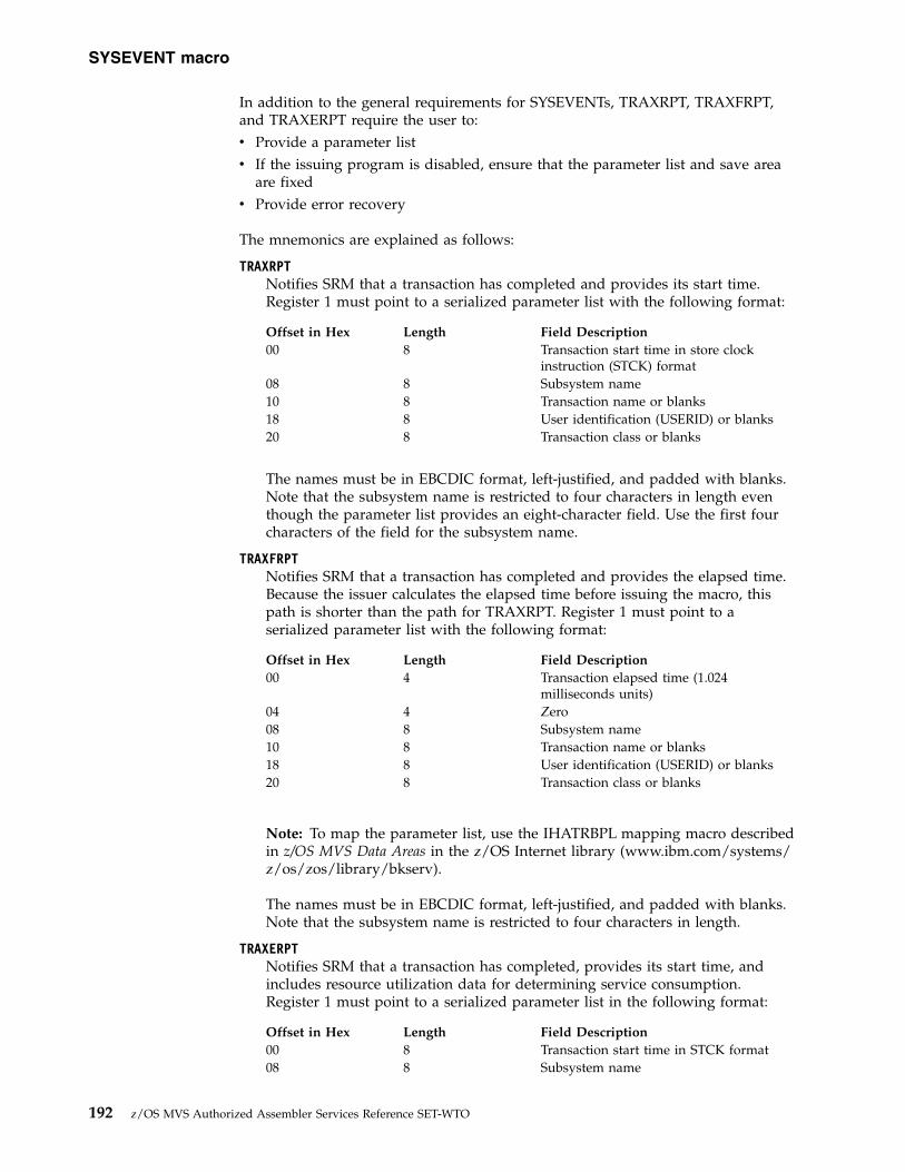
In addition to the general requirements for SYSEVENTs, TRAXRPT, TRAXFRPT,and TRAXERPT require the user to:v Provide a parameter listv If the issuing program is disabled, ensure that the parameter list and save area
are fixedv Provide error recovery
The mnemonics are explained as follows:
TRAXRPTNotifies SRM that a transaction has completed and provides its start time.Register 1 must point to a serialized parameter list with the following format:
Offset in Hex Length Field Description00 8 Transaction start time in store clock
instruction (STCK) format08 8 Subsystem name10 8 Transaction name or blanks18 8 User identification (USERID) or blanks20 8 Transaction class or blanks
The names must be in EBCDIC format, left-justified, and padded with blanks.Note that the subsystem name is restricted to four characters in length eventhough the parameter list provides an eight-character field. Use the first fourcharacters of the field for the subsystem name.
TRAXFRPTNotifies SRM that a transaction has completed and provides the elapsed time.Because the issuer calculates the elapsed time before issuing the macro, thispath is shorter than the path for TRAXRPT. Register 1 must point to aserialized parameter list with the following format:
Offset in Hex Length Field Description00 4 Transaction elapsed time (1.024
milliseconds units)04 4 Zero08 8 Subsystem name10 8 Transaction name or blanks18 8 User identification (USERID) or blanks20 8 Transaction class or blanks
Note: To map the parameter list, use the IHATRBPL mapping macro describedin z/OS MVS Data Areas in the z/OS Internet library (www.ibm.com/systems/z/os/zos/library/bkserv).
The names must be in EBCDIC format, left-justified, and padded with blanks.Note that the subsystem name is restricted to four characters in length.
TRAXERPTNotifies SRM that a transaction has completed, provides its start time, andincludes resource utilization data for determining service consumption.Register 1 must point to a serialized parameter list in the following format:
Offset in Hex Length Field Description00 8 Transaction start time in STCK format08 8 Subsystem name
SYSEVENT macro
192 z/OS MVS Authorized Assembler Services Reference SET-WTO

Offset in Hex Length Field Description10 8 Transaction name or blanks18 8 User identification (USERID) or blanks20 8 Transaction class or blanks28 8 Task (TCB) time in STCK format or zeros30 8 SRB time in STCK format or zeros38 8 Main storage occupancy in page seconds
(pages times msec, where msec is task(TCB) time in 1.024 millisecond units)
40 4 Logical I/O count or zeros44 1 X'00' if the previous field contains the
logical I/O count, X'80' if the previousfield contains the device connect timeinterval (DCTI)
45 3 Reserved must be zero
Note: To map the parameter list, use the IHATREPL mapping macro describedin z/OS MVS Data Areas in the z/OS Internet library (www.ibm.com/systems/z/os/zos/library/bkserv).
The names must be in EBCDIC format, left-justified, and padded with blanks.Note that the subsystem name is restricted to four characters in length.
Return and reason codesWhen processing is completed for TRAXRPT, TRAXFRPT, and TRAXERPTSYSEVENTs, the subsystem regains control at the instruction following theSYSEVENT macro. The last byte of register 15 contains one of the followinghexadecimal return codes:
Table 26. Return Codes for the SYSEVENT Macro
Return Code Meaning
00 Data for the transaction has been reported successfully to the SRM.
08 Processing could not be completed at this time. No queue elements areavailable for recording the data. No data is reported to the SRM, but animmediate reissue could be successful.
0C Reporting is temporarily suspended for one of the following reasons:
v RMF workload activity reporting is not active.
v The TOD clock is stopped.
No data is reported, but a later reissue could be successful.
10 Reporting is inoperative. The TOD clock is in error or the reportinginterface is not installed. No data is reported.
Example 1Use the SYSEVENT TRAXRPT to report transaction data providing transactionidentifiers and the transaction start time. In the following example, TRAXDESC isthe name of a storage area that is initialized with the subsystem name, transactionname, user ID and class information needed to pass to SRM:...Transaction begins Initialize transaction identifiers
(TRAXDESC)STCK INITTIME Save start time.
SYSEVENT macro
Chapter 18. SYSEVENT — System event 193
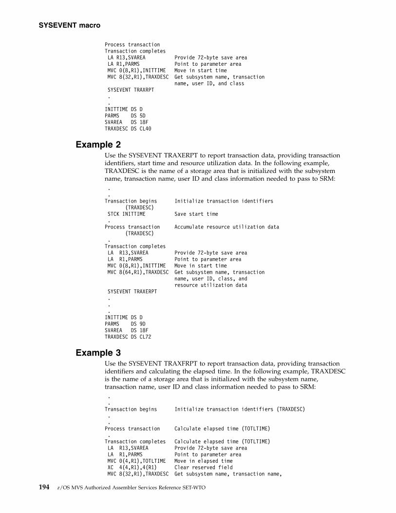
Process transactionTransaction completesLA R13,SVAREA Provide 72-byte save areaLA R1,PARMS Point to parameter areaMVC 0(8,R1),INITTIME Move in start timeMVC 8(32,R1),TRAXDESC Get subsystem name, transaction
name, user ID, and classSYSEVENT TRAXRPT..INITTIME DS DPARMS DS 5DSVAREA DS 18FTRAXDESC DS CL40
Example 2Use the SYSEVENT TRAXERPT to report transaction data, providing transactionidentifiers, start time and resource utilization data. In the following example,TRAXDESC is the name of a storage area that is initialized with the subsystemname, transaction name, user ID and class information needed to pass to SRM:..Transaction begins Initialize transaction identifiers
(TRAXDESC)STCK INITTIME Save start time.Process transaction Accumulate resource utilization data
(TRAXDESC).Transaction completesLA R13,SVAREA Provide 72-byte save areaLA R1,PARMS Point to parameter areaMVC 0(8,R1),INITTIME Move in start timeMVC 8(64,R1),TRAXDESC Get subsystem name, transaction
name, user ID, class, andresource utilization data
SYSEVENT TRAXERPT...INITTIME DS DPARMS DS 9DSVAREA DS 18FTRAXDESC DS CL72
Example 3Use the SYSEVENT TRAXFRPT to report transaction data, providing transactionidentifiers and calculating the elapsed time. In the following example, TRAXDESCis the name of a storage area that is initialized with the subsystem name,transaction name, user ID and class information needed to pass to SRM:..Transaction begins Initialize transaction identifiers (TRAXDESC)..Process transaction Calculate elapsed time (TOTLTIME).Transaction completes Calculate elapsed time (TOTLTIME)LA R13,SVAREA Provide 72-byte save areaLA R1,PARMS Point to parameter areaMVC 0(4,R1),TOTLTIME Move in elapsed timeXC 4(4,R1),4(R1) Clear reserved fieldMVC 8(32,R1),TRAXDESC Get subsystem name, transaction name,
SYSEVENT macro
194 z/OS MVS Authorized Assembler Services Reference SET-WTO

user ID, and classSYSEVENT TRAXFRPT...TOTLTIME DS FPARMS DS 5DSVAREA DS 18FTRAXDESC DS CL40
Control swapping (DONTSWAP, OKSWAP, TRANSWAP)The SYSEVENTs DONTSWAP, OKSWAP, and TRANSWAP control swapping. Thechoice of mnemonic depends on the period of time for which the address space isto be non-swappable.
For a short period of time (less than one minute), use DONTSWAP to make itnon-swappable and OKSWAP to make it swappable.
For an extended period of time (more than one minute), use TRANSWAP to makethe address space non-swappable and OKSWAP to make it swappable.
Note: If you specify an ASID with DONTSWAP, OKSWAP, or TRANSWAP, thatASID must specify the home address space. This means, you can only controlswapping in the address space in which the SYSEVENT is issued. If you specifyanother address space the request cannot be carried out.
The mnemonics are explained as follows:
DONTSWAPNotifies SRM that the address space from which this SYSEVENT is issuedcannot be swapped out until the system receives a matching OKSWAP for eachDONTSWAP issued or until the jobstep ends.
No input parameters are required. One of the following codes will be returnedin register 1, byte 3:
Hexadecimal Code Meaning
00 The request was honored.
04 The request was not honored because it was not for the current addressspace.
08 The request was not honored because the issuer was not authorized or theoutstanding count of DONTSWAP requests had reached its maximum.
OKSWAPNotifies SRM that the address space from which the SYSEVENT was issuedcan be considered for swapping.
No input parameters are required. One of the following codes will be returnedin register 1, byte 3:
Hexadecimal Code Meaning
00 The request was honored.
04 The request was not honored because it was not for the current addressspace.
08 The request was not honored because the issuer was not authorized.
SYSEVENT macro
Chapter 18. SYSEVENT — System event 195

TRANSWAPForces a swap out. After the subsequent swap-in, frames are allocated frompreferred storage and the address space is non-swappable. TRANSWAPprevents programs from allocating frames in reconfigurable storage. If theprogram issuing SYSEVENT depends on the transition to complete, you shouldensure that register 1 contains the address of an ECB. SYSEVENT will thenpost this ECB when it swaps out the address space. If no dependency exists,set register 1 to 0 (zero).
One of the following codes will be returned in register 1, byte 3:
Hexadecimal Code Meaning
00 The request was honored. If an ECB was specified, your program shouldissue a WAIT macro specifying the same ECB.
04 The transition was previously done or the address space is permanentlynon-swappable. If an ECB was specified it will not be posted.
If an ECB was specified, the following POST codes may occur in the last threebytes of the ECB:
Hexadecimal Code Meaning
000000 The transition is complete.
000004 The address space became non-swappable before it could be swapped out.
Example 1To make the current address space non-swappable for a time period of less thanone minute, specify the following:SYSEVENT DONTSWAP
.
.
.SYSEVENT OKSWAP
Example 2To make the current address space non-swappable for an indefinite period of time,specify the following:
SYSEVENT TRANSWAPST 1,RETCODECLI TSWP_RC,0BNE FAILEDWTO ’TSWP SUCCESSFUL’...B DONE
FAILED EQU *WTO ’TSWP UNSUCCESSFUL (BAD RC)’
DONE EQU *...
RETCODE DS 0FDS CL3
TSWP_RC DS FL1
Obtain system measurement information (STGTEST)The STGTEST SYSEVENT provides information about the current physical use ofresources. This is not an indication of how much virtual storage your installationallows you to obtain. For more information on obtaining virtual storage forhiperspaces or data spaces, see DSPSERV.
SYSEVENT macro
196 z/OS MVS Authorized Assembler Services Reference SET-WTO

The user must supply the address of a storage area large enough to store therequested data.
STGTESTReturns information about the amount of storage available in the system. Thepurpose of SYSEVENT STGTEST is to help an application decide whether touse an additional virtual storage area, such as a hiperspace.
When you use this information, be aware of the dynamic nature of storage.
The output of the SYSEVENT STGTEST only reflects the current state ofstorage and does not reserve this storage for the caller, or guarantee that it isavailable for use.
Note: When the address space which issues the SYSEVENT STGTEST isassociated with a memory pool, the values in the output area are limited bythe memory pool size.
Register 1 must contain the address of a three-word output area where SRM is toreturn the information. After SRM returns, each word contains a storage amountthat represents a specific number of frames. Before you choose a number to use asthe basis for decision, be aware of how your decision affects the performance ofthe system. The meaning of the returned values is:v Use of the first number affects system performance little, if at all.v Use of the second number might affect system performance to some degree.v Use of the third number might substantially affect system performance.
If you base decisions on the value in the second or third word, SRM can takeprocessor storage away from other programs and replace it with auxiliary storage.
Note: Currently, the value returned in the third word is always the same as thevalue returned in the second word.
Note: Address spaces, which are members of a WLM resource group and has amemory limit are subject to various memory pool thresholds and the associatedsystem actions. These address spaces are independent of the values returned bySTGTEST. Refer to z/OS MVS Initialization and Tuning Guide for more informationon managing WLM resource groups and memory pools.
ExampleAn application needs a standard hiperspace. Before it makes the request, theapplication uses SYSEVENT STGTEST to find out how much storage is available.The values that SRM returns determine how large a hiperspace the applicationcreates.
To obtain a report on the storage available in the system, specify the following:LA 1,ESPARMSYSEVENT STGTEST
.
.ESPARM DS 3F
The application bases its decision on the numbers in the first and second words ofthe output area.
SYSEVENT macro
Chapter 18. SYSEVENT — System event 197
|||
|||||

Obtain address space classification information (REQASCL)The REQASCL SYSEVENT provides information about an address space'sclassification information. You must specify the address space id (ASID) with eitherthe ASID=register or the ASIDL=asid parameter.
The user must supply the address of a storage area large enough to hold therequested data.
REQASCLReturns classification information about an address space.
The name is in EBCDIC format, left-justified, and padded with blanks.
Input register informationRegister 1 must point to a parameter list. The parameter list for REQASCL must benon-pageable and addressable via the caller's primary address space. To map theparameter list for REQASCL, use the IRARASC mapping macro described in z/OSMVS Data Areas in the z/OS Internet library (www.ibm.com/systems/z/os/zos/library/bkserv). The caller must set the RASC_ACRO, RASC_VERSION, andRASC_LENGTH fields. The IRARASC macro defines constants for this purpose.The following table lists the constants which contain the correct values for eachfield:
Table 27. Fields and constants
Field Constant
RASC_ACRO RASC_ID_CONSTANT
RASC_VERSION RASC_CURRENTVERSION
RASC_LENGTH RASC_CURRENTVERSION_LEN
Return and reason codesWhen processing is complete for the REQASCL, the last byte of register 15 containsone of the following hexadecimal return codes:
Table 28. Return Codes for REQASCL
Return Code Meaning
00 Successful completion.
04 Classification information returned may not reflect how the address spaceis being managed.
08 Input parameter list is not properly initialized (eyecatcher, version or sizespecified is too small).
12 Classification information is not available.
Input register informationRegister 1 must point to a parameter list, as mapped by the IRARASC macro.
Obtain address space related information (REQASD and REQFASD)The SYSEVENTs REQASD and REQFASD provide information about an addressspace's workload activity. You must specify the address space id (ASID) with eitherthe ASID=register or the ASIDL=asid parameter.
SYSEVENT macro
198 z/OS MVS Authorized Assembler Services Reference SET-WTO
Both return the same kind of information. REQFASD is quicker; it does notserialize data collection, and does not provide recovery of its own. The user mustprovide the recovery for REQFASD.
The user must supply the address of a storage area large enough to hold therequested data.
REQASDReturns workload activity information about an address space.
REQFASDReturns the same information as REQASD, but is a fast path SYSEVENT, withno recovery of its own.
TYPE=SIZECHECKRequired parameter which activates work area size checking and shouldalways be specified.
Input register information
REQASDFor REQASD, register 1 must point to a parameter list. The parameter list must benon-pageable and addressable via the caller's primary address space. To map theparameter list, use the IRARASD mapping macro described in z/OS MVS DataAreas in the z/OS Internet library (www.ibm.com/systems/z/os/zos/library/bkserv).
The RASDLEN field must be filled in with the length of the RASD parameter listarea that is to be used by the SYSEVENT. The constant RASDSIZE can be used tofill in the RASDLEN field.
REQFASDFor REQFASD, register 1 must point to a parameter list. The parameter list must beaddressable via the caller's primary address space. To map the parameter list, usethe IRARASD mapping macro described in z/OS MVS Data Areas in the z/OSInternet library (www.ibm.com/systems/z/os/zos/library/bkserv).
The RASDLEN field must be filled in with the length of the RASD parameter listarea that is to be used by the SYSEVENT. The constant RASDSIZE can be used tofill in the RASDLEN field.
SYSEVENT REQFASD requires a workarea for the processing. The size of theworkarea can be found in the constant RQFASDWA, which is defined in theIRARASD mapping. Additionally, it is necessary to fill the RASDWALEN with theprovided workarea length. Prior to executing REQFASD, register 13 must point toa workarea. The workarea must be addressable via the caller's primary addressspace.
Return and reason codesWhen processing is complete for the REQASD and REQFASD SYSEVENTS, the lastbyte of register 15 contains one of the following hexadecimal return codes:
Table 29. Return Codes for REQASD and REQFASD
Return Code Meaning
00 Successful completion.
SYSEVENT macro
Chapter 18. SYSEVENT — System event 199

Table 29. Return Codes for REQASD and REQFASD (continued)
Return Code Meaning
04 Processing could not be completed at this time. A mode switch or policyactivation is in progress. A later reissue could be successful.
08 The parameter list is too small.
12 The ASID is not valid.
16 Work area is too small (only issued by REQFASD).
Example 1Use the SYSEVENT REQASD to extract address space information:
LA R1,Parmlist Load parameter list addressUSING RASD,R1 Map parameter list with RASDMVC RASDACRO,=C’RASD’ Set eyecatcher
MVC RASDLEN,=AL2(L’Parmlist) Set parameter list lengthSYSEVENT REQASD,TYPE=SIZECHECK,ENTRY=BRANCH,ASID=(0)...
Parmlist DS CL(RASDSIZE)
Example 2Use the SYSEVENT REQFASD to extract address space information:
LA R1,Parmlist Load parameter list addressUSING RASD,R1 Map parameter list with RASDMVC RASDACRO,=C’RASD’ Set eyecatcher
MVC RASDLEN,=AL2(L’Parmlist) Set parameter list lengthMVC RASDWALEN,=AL2(L’Workarea) and Workarea length in RASDLR R2,R13 Save R13 prior Sysevent invocationLA R13,Workarea Address the workarea with R13SYSEVENT REQFASD,TYPE=SIZECHECK,ENTRY=BRANCH,ASID=(0)LR R13,R2 Restore R13...
Parmlist DS CL(RASDSIZE)Workarea DS CL(RQFASDWA)
Obtain workload management mode status information (REQSRMST)The REQSRMST SYSEVENT allows to obtain information about the state ofworkload management. It returns a parameter list that includes, for example:v Active service policy informationv When and where the policy was activatedv Active service definition informationv When and where the service definition was installed
Note: The SRMSTCAP flag is provided to prospective callers of the REQLPDATSYSEVENT, to test if that SYSEVENT is available on the system. On systems priorto z/OS V1R3, callers should first invoke the REQSRMST SYSEVENT and checkthe SRMSTCAP flag before invoking the REQLPDAT SYSEVENT. See “Obtain datafor defined capacity (REQLPDAT)” on page 201 for more information.
Input register informationRegister 1 must point to a parameter list. The parameter list must be non-pageableand addressable via the caller's primary address space. To map the parameter list,use the IRASRMST mapping macro described in z/OS MVS Data Areas in the z/OSInternet library (www.ibm.com/systems/z/os/zos/library/bkserv). The
SYSEVENT macro
200 z/OS MVS Authorized Assembler Services Reference SET-WTO

SRMSTLEN field must be filled in with the length of this parameter list. Theconstant SRMSTSIZ can be used to set this length.
Return and reason codesWhen processing is complete for the REQSRMST SYSEVENT, the last byte ofregister 15 contains one of the following hexadecimal return codes:
Table 30. Return Codes for REQSRMST
Return Code Meaning
00 Successful completion.
08 The parameter list is too small.
Obtain data for defined capacity (REQLPDAT)The REQLPDAT SYSEVENT allows to obtain performance data related to a definedcapacity. For example, defined capacity and group capping can be used withSub-Capacity pricing models.
This performance data is used on monitoring products such as RMF to betteranalyze the following:v The average CPU consumption of the partitionv The frequency of WLM capping the partition to enforce the defined capacityv The average weight of the partition
Note:
1. The parameter area for REQLPDAT is mapped by macro IRALPDAT.The only input to REQLPDAT is field LPDATLEN in the parameter area. Youmust set LPDATLEN to the length of the provided parameter area beforeinvoking the REQLPDAT SYSEVENT. Take one of the following actions:v Set LPDATLEN to 0v Set LPDATLEN using equate LPDATPARMLENGTH and provide a
parameter area that is at least LPDATPARMLENGTH bytesv Obtain a sufficiently large parameter area of more than
LPDATPARMLENGTH bytes and set LPDATLEN accordingly2. The parameter area contains variable data and the parameter area length can
change at any time, not just with a new release of z/OS. Therefore, you mustcheck the return code from REQLPDAT. If the input LPDATLEN value issmaller than the needed size of the parameter area, the SYSEVENT returns withreturn code 04. In this case, the system sets the LPDATLEN field to the actualneeded length of the parameter area. You must call REQLPDAT again with aparameter area that is at least LPDATLEN bytes long. Make sure that theLPDATLEN field indicates the length of the provided area.
3. An unauthorized caller can call the REQLPDAT SYSEVENT with theENTRY=UNAUTHPC option.
Input register informationRegister 1 must point to a parameter list. For ENTRY=BRANCH and ENTRY=SVCthe parameter list must be non-pageable. It must be addressable by the caller’sprimary address space. To map the parameter list, use the IRALPDAT mappingmacro described in z/OS MVS Data Areas in the z/OS Internet library(www.ibm.com/systems/z/os/zos/library/bkserv).
SYSEVENT macro
Chapter 18. SYSEVENT — System event 201

Return and reason codesWhen processing is complete for the REQLPDAT SYSEVENT, the last byte ofregister 15 contains one of the following hexadecimal return codes:
Table 31. Return Codes for REQLPDAT
Return Code Meaning
00 Successful completion.
04 The parameter list is too small.
Identify holder of a resource (ENQHOLD)Use the ENQHOLD SYSEVENT to identify a holder of a resource causingcontention. SRM may boost the service to the resource holder to help resolve thecontention more quickly. A holder can be either an address space or an enclave.You must specify the address space or enclave in the parameter list pointed to byregister 1. Use the IRAEVPL mapping macro described in z/OS MVS Data Areas inthe z/OS Internet library (www.ibm.com/systems/z/os/zos/library/bkserv).Specify either the ASID or STOKEN value for the address space or the enclavetoken for the enclave. The enclave token must have been obtained from theIWMECREA macro or IWMESQRY macro.
Specify parameter TYPE=3 for SYSEVENT ENQHOLD and ENQRLSE to pass thefollowing data to SRM:
Subsystem informationSpecify subsystem information that will be kept by SRM for RAS purposesand is formatted in IPCS.
Enqueue promotion function requestChoose either the standard enqueue management promotion, or the shorttime/high frequency enqueue promotion:1. Standard enqueue promotion:
Use the SYSEVENT ENQHOLD to signal a resource contention to SRMand use the SYSEVENT ENQRLSE when the resource contention ends.This function causes SRM to boost the service to the resource holder forthe number of service units defined by the ERV parameter in theIEAOPTXX member.
2. Short time/high frequency enqueue promotion:Use the SYSEVENT ENQHOLD to signal a short time resourcecontention to SRM. This function causes SRM to boost the service to theholder of the resource for a small number of service units and afterthat, terminates this enqueue promotion process. For this reason, noSYSEVENT ENQRLSE is required nor should one be issued. Noenqueue hold token is provided by SRM for this function in theparameter list.
Note: The number of service units used by SRM to boost the resourceholder for a short time/high frequency enqueue promotion is a fixedvalue and cannot be modified. It has no relation to the ERV parameterin the IEAOPTxx member.
You can select the enqueue promotion functions with the FUNCTIONparameter in the parameter list pointed to by register 1.
SYSEVENT macro
202 z/OS MVS Authorized Assembler Services Reference SET-WTO

Enqueue hold tokenReceive an output token from the ENQHOLD request and use the sametoken on the matching ENQRLSE request. The enqueue hold token is onlyvalid for the standard enqueue management promotion.
When using enclaves for tasks that serialize on resources using the ENQ macro orthe latch manager callable services, note that a task cannot change its transactionstatus. That is, it cannot join or leave an enclave, while holding a resource usingENQ or the latch manager. Otherwise, enqueue promotion processing might notwork properly. The recommended sequence is:1. Join an enclave (through IWMEJOIN, IWMSTBGN, or SYSEVENT ENCASSOC).2. Obtain resource with ENQ or latch manager.3. Process using serialized resource.4. Release resource.5. Leave an enclave (through IWMELEAV, IWMSTEND, or SYSEVENT
ENCASSOC).
In addition, to ensure correct enqueue promotion processing, a task executing in anenclave should not make the following types of ENQ requests:v Directed enqueues, that is, issuing the ENQ macro with the TCB= parameterv Matching task enqueues, that is, issuing the ENQ macro with the MTCB or
MASID parameter.
Input register informationIf this SYSEVENT is invoked with the TYPE=3 keyword, then register 1 must pointto a parameter list. The parameter list must be non-pageable and addressable viathe caller's primary address space. To map the parameter list, use the IRAEVPLmapping macro described in z/OS MVS Data Areas in the z/OS Internet library(www.ibm.com/systems/z/os/zos/library/bkserv).
Return and reason codesWhen processing is complete for the ENQHOLD SYSEVENT, the last byte ofregister 15 contains one of the following hexadecimal return codes:
Table 32. Return Codes for ENQHOLD
Return Code (Decimal) Meaning
00 Successful completion.
08 Invalid enclave token specified.
10 The ASID specified did not map to a valid, active address space. This mayoccur because the address space it represents is no longer active or wasnever active.Note: Only valid if parameter IraEnqHR_FLAGS_RhTerm=1 was specifiedin the parameter list.
12 The STOKEN specified did not map to a valid, active address space. Thismay occur because the address space it represents is no longer active orwas never active.Note: Only valid if parameter IraEnqHR_FLAGS_RhTerm=1 was specifiedin the parameter list.
14 The TCB address specified did not map to a valid, active TCB. This mayoccur because the TCB address is no longer active or was never active.
16 Invalid combination of ASID, STOKEN, or enclave token was specified inthe parameter list. Specify either ASID, or STOKEN, or enclave token.
SYSEVENT macro
Chapter 18. SYSEVENT — System event 203

Identify that a holder has released resource (ENQRLSE)Use the ENQRLSE SYSEVENT to notify SRM that the holder of a resource causingcontention has released the resource. The inputs must be the same as those for theENQHOLD SYSEVENT previously issued for the holder including the specificationof parameter TYPE=3. See the description of ENQHOLD for considerations relatedto using enclaves for tasks that serialize resources. Do not issue SYSEVENTENQRLSE if you have selected the short time/high frequency enqueue promotion.
Input register informationIf this SYSEVENT is invoked with the TYPE=3 keyword, then register 1 must pointto a parameter list. The parameter list must be non-pageable and addressable viathe caller's primary address space. To map the parameter list, use the IRAEVPLmapping macro described in z/OS MVS Data Areas in the z/OS Internet library(www.ibm.com/systems/z/os/zos/library/bkserv).
Return and reason codesWhen processing is complete for the ENQRLSE SYSEVENT, the last byte of register15 contains one of the following hexadecimal return codes:
Table 33. Return Codes for ENQRLSE
Return Code Meaning
00 Successful completion.
08 Enclave token is invalid.
10 The ASID specified did not map to a valid, active address space. This mayoccur because the address space it represents is no longer active or wasnever active.Note: Only valid if parameter IraEnqHR_FLAGS_RhTerm=1 was specifiedin the parameter list.
12 The STOKEN specified did not map to a valid, active address space. Thismay occur because the address space it represents is no longer active orwas never active.Note: Only valid if parameter IraEnqHR_FLAGS_RhTerm=1 was specifiedin the parameter list.
16 Invalid combination of ASID, STOKEN, or enclave token was specified inthe parameter list. Specify either ASID, or STOKEN, or enclave token.
Associate an enclave with an address space (ENCASSOC)Use the ENCASSOC SYSEVENT to associate an enclave and a server address spacefor SRBs that were scheduled to run in this enclave. This association allows SRM tomanage the server address space’s storage related resources towards the enclave’sperformance goal.
Note:
1. It is not required to use SYSEVENT ENCASSOC when you run SRBs inenclaves. It is an improvement for storage management but it is notrecommended when the address space into which the SRB is scheduled runsother significant work because the association may change the goalmanagement for the target address space.
2. The ENCASSOC SYSEVENT is necessary only for SRBs that were scheduled torun in this enclave. A task that joins an enclave automatically associates thehome address space with the enclave.
SYSEVENT macro
204 z/OS MVS Authorized Assembler Services Reference SET-WTO

You must specify X'8000' in the ASID parameter and access registers (AR) 0 and 1must contain the enclave token. The enclave token must have been obtained fromthe IWMECREA macro.
The ENCASSOC SYSEVENT supports the following functions, which have to bespecified with the TYPE parameter as well as in the parameter list IRAEVPL. Validvalues are ‘1’ and ‘2’. Note that the value can be specified either as a decimalnumber or as a symbol.
TYPE=1Allows the SRB to associate this enclave with the address space for thepurpose of managing the storage related resources towards the enclave’sperformance goal.
TYPE=2Allows the SRB to disassociate this enclave with the address space.
For more information about SRBs and how to use them, see z/OS MVSProgramming: Authorized Assembler Services Guide.
The recommended coding sequence of the ENCASSOC SYSEVENT is as follows:1. Subsystem:v The subsystem creates the enclave by using the IWMECREA service.v The subsystem schedules an SRB to run in the enclave.
2. SRB:v The SRB associates the address space with the enclave by using the
ENCASSOC SYSEVENT function Associate.v SRB process logic.v The SRB disassociates the address space with the enclave by using the
ENCASSOC SYSEVENT function Disassociate.
Input register informationRegister 1 must point to a parameter list. The parameter list must be non-pageableand addressable via the caller's primary address space. To map the parameter list,use the IRAEVPL mapping macro described in z/OS MVS Data Areas in the z/OSInternet library (www.ibm.com/systems/z/os/zos/library/bkserv).
Return and reason codesWhen processing is complete for the ENCASSOC SYSEVENT, the last byte ofregister 15 contains one of the following hexadecimal return codes:
Table 34. Return Codes for ENCASSOC
Return Code Meaning
00 Successful completion.
04 Invalid function code specified.
10 Invalid enclave token specified.
SYSEVENT macro
Chapter 18. SYSEVENT — System event 205

Set the state for an enclave (ENCSTATE)Use the ENCSTATE SYSEVENT to set the state of an enclave to either idle ornon-idle. Specify X'8000' in the ASID parameter. Access registers (AR) 0 and 1 mustcontain the enclave token. The enclave token must have been obtained from theIWMECREA macro. An independent enclave must not be set idle as long as thereare non-idle work-dependent enclaves associated with it.
Input register informationRegister 1 must point to a parameter list. The parameter list must be non-pageableand addressable via the caller's primary address space. To map the parameter list,use the IRAEVPL mapping macro described in z/OS MVS Data Areas in the z/OSInternet library (www.ibm.com/systems/z/os/zos/library/bkserv).
Access register (AR) 0 and 1 must contain the enclave token whose state you aresetting.
Query amount of free AUX storage (FREEAUX)Use the FREEAUX SYSEVENT to receive the number of free AUX storage slots thatcan safely be used without causing an AUX shortage.
Output register informationRegister 0 will contain the recommended number of free AUX storage slots.
Return resource contention information (QRYCONT)Use SYSEVENT QRYCONT to return the resource contention information for eitheran address space or an enclave. You must specify the address space or enclave inthe parameter list pointed to by register 1. Use the IRAEVPL mapping macrodescribed in z/OS MVS Data Areas in the z/OS Internet library(www.ibm.com/systems/z/os/zos/library/bkserv). Specify either the ASID orSTOKEN value for the address space or the enclave token for the enclave. Theenclave token must have been obtained from the IWMECREA macro or theIWMESQRY macro.
Input register informationRegister 1 must point to a parameter list. The parameter list must be non-pageablefor authorized SYSEVENT calls (ENTRY=SVC, ENTRY=BRANCH) and must beaddressable via the caller's primary address space. To map the parameter list, usethe IRAEVPL mapping macro described in z/OS MVS Data Areas in the z/OSInternet library (www.ibm.com/systems/z/os/zos/library/bkserv).
Return codesWhen processing is complete for the SYSEVENT QRYCONT, the last byte ofregister 15 contains one of the following hexadecimal return codes:
Table 35. Return Codes for REQLPDAT
Return Code (decimal) Meaning
00 Successful completion.
04 No contention information available.
08 Invalid enclave token specified.
SYSEVENT macro
206 z/OS MVS Authorized Assembler Services Reference SET-WTO

Table 35. Return Codes for REQLPDAT (continued)
Return Code (decimal) Meaning
10 The ASID specified did not map to a valid, active address space. This mayoccur because the address space it represents is no longer active or wasnever active.
12 The STOKEN specified did not map to a valid, active address space. Thismay occur because the address space it represents is no longer active orwas never active.
14 Invalid combination of ASID, STOKEN, or enclave token was specified inthe parameter list. Specify either ASID, STOKEN, or enclave token.
16 There is additional resource contention information available.
18 Invalid version, length, or eye catcher was specified in the parameter list.
20 Invalid request type was specified in the parameter list.
Query a virtual server (QVS)Products can use the query virtual server (QVS) interface to obtain a virtualserver's ID and capacity. A virtual server is the “logical hardware” environment inwhich an image runs. In the case of an image running in a logical partition, thevirtual server is the logical partition. In the case of an image running as a firstlevel VM guest, the virtual server is the first level guest. Note that the virtualserver concept is not extended to second or higher level VM guests. In those cases,the virtual server is still considered to be the first level VM guest. For an imagerunning in basic mode, the virtual server is the whole machine. In other words, fora CPC in basic mode, the logical hardware environment equals the physicalhardware environment.
Customers can define a capacity limit for each logical partition. This limit isenforced by Workload Manager based on the average CPU usage of the logicalpartition. Peaks of CPU usage are allowed above the limit as long as the averageCPU usage stays below the limit.
This service gives software vendors or software providers the option of licensingtheir software to a virtual server.
One way a software product can use the virtual server ID and capacity queryservice is to call the service when it starts. Based on the information returned, theproduct can verify that it is licensed to run on the specific virtual server and thatthe virtual server does not have more capacity than the product is licensed for.Note that this service does not make any of these licensing checks — it simplyreturns the information to enable a software product to make the appropriatechecks based on the conditions of its license.
Along with this SYSEVENT, there is also a C interface, IWMQVS (located inSYS1.CSSLIB). Both forms of this query return a QVS structure which maps thereturned identification and capacity information. The assembler mapping isprovided by the macro IRAQVS, and the C/C++ mapping is provided inIWMQVS.H (located in SYS1.SIEAHDR.H). Before calling this service, the callermust provide storage for the QVS structure and set the field QvsLen to the lengthof the structure. On return, the caller can look at fields QvsVer and QvsFlags todetermine which fields have been filled in. QvsFlags contains the following flags:
QvsCecValidThe physical hardware level information is valid.
SYSEVENT macro
Chapter 18. SYSEVENT — System event 207

QvsImgValidThe logical partition level information is valid. This flag will be off if notrunning in logical partition mode.
QvsVmValidThe virtual machine information is valid. This flag will be off if notrunning in a virtual machine.
The physical hardware level information is provided in the following fields:v QvsCecManufacturerNamev QvsCecPlantofManufacturev QvsCecMachineTypev QvsCecModelIdv QvsCecSequenceCodev QvsCecCapacityv QvsCecCapacityStatus
The logical partition level information is provided in the following fields:v QvsImgLogicalPartitionIdv QvsImgLogicalPartitionNamev QvsImgCapacity
The virtual machine information is provided in the following fields:v QvsVmNamev QvsVmCapacity
QvsCecCapacity, QvsImgCapacity, and QvsVmCapacity contain the maximumservice rate that theoretically could be achieved at each level. The value is inmillions of service units per hour (MSU).
QvsCecCapacity is equal to the individual CPU speed multiplied by the number ofonline and offline physical CPUs.
QvsCecCapacityStatus indicates if the machine is running at nominal capacity or atreduced capacity.
If QvsImgValid is on, the image is in ESAME mode, and QvsVmValid is off, thenQvsImgCapacity is equal to one of the following:v The partition's defined capacity set via the Hardware Management Console, if
anyv The individual CPU speed multiplied by the number of online and offline
logical CPUs, if the partition is uncapped and has no defined capacityv The capacity at the partition's weight, if the partition is capped via the
Hardware Management Console.
If QvsImgValid is on, and either the image is in ESA/390 mode or QvsVmValid ison, then QvsImgCapacity is equal to the individual CPU speed multiplied by thenumber of online and offline logical CPUs.
QvsVmCapacity is the individual CPU speed multiplied by the number of onlineand offline virtual CPUs.
SYSEVENT macro
208 z/OS MVS Authorized Assembler Services Reference SET-WTO

In all cases, the individual CPU speed in based on the MP factor for the number ofonline and offline physical CPUs.
Note that the capacity of a virtual server can change dynamically. One example ofa dynamic capacity change is a CPU upgrade on demand of the underlyinghardware. A second example is a dynamic change of the defined capacity limit fora logical partition. If an unauthorized program is interested in knowing aboutdynamic capacity changes, it must poll the virtual server ID and capacity queryservice. Given dynamic capacity changes are rare, a low polling rate should besufficient.
Authorized programs interested in knowing about dynamic capacity changes canalso listen for ENF signal 61. This ENF is signaled when a change in dynamiccapacity occurs and provides the listener exit the new capacity at each level in thehierarchy.
Return and reason codesWhen processing is complete for the QVS SYSEVENT, the last byte of register 15contains one of the following hexadecimal return codes:
Table 36. Return Codes for QVS
Return Code Meaning
00 Successful completion.
04 The parameter list is too small.
SYSEVENT macro
Chapter 18. SYSEVENT — System event 209

SYSEVENT macro
210 z/OS MVS Authorized Assembler Services Reference SET-WTO

Chapter 19. TCBTOKEN — Request or translate the TTOKEN
DescriptionThe TTOKEN is the 16-byte identifier of a task. Unlike a TCB address, eachTTOKEN is unique within the IPL; the system does not reassign this sameidentifier to any other TCB.
The TCBTOKEN macro provides five mutually exclusive services depending onhow you specify the TYPE parameter:v TYPE=TOTTOKEN gives you the TTOKEN for the task associated with a
specified TCB address.v TYPE=TOTCB gives you the TCB address for a specified TTOKEN.v TYPE=CURRENT gives you the TTOKEN for the current task.v TYPE=PARENT gives you the TTOKEN for the task that attached the current
task.v TYPE=JOBSTEP gives you the TTOKEN for the job step task.
Typical situations when you would use TYPE=TOTTOKEN are:v When you create a data space and want to assign ownership of the data space to
a second task.In this case, you know the TCB address for the second task, but you don't knowits TTOKEN (for input to the DSPSERV CREATE macro). UseTYPE=TOTTOKEN to obtain the TTOKEN.
v When you want to delete a data space you do not own.In this case, you know the TCB address for the other task, but you don't knowits TTOKEN (for input to the DSPSERV DELETE macro). Use TYPE=TOTTOKENto obtain the TTOKEN.
v When you want to know whether the owner of a data space still exists.In this case, you know the TTOKEN for the owning task. If the system returnsthe TCB address in response to the TYPE=TOTCB parameter, the task still exists.
z/OS MVS Programming: Extended Addressability Guide describes STOKENs andTTOKENs.
EnvironmentThe requirements for the caller are:
Environmental factor RequirementMinimum authorization: Problem or supervisor state, any PSW keyDispatchable unit mode: For TOTTOKEN or TOTCB requests, the caller can be in
task or SRB mode. For CURRENT, PARENT, and JOBSTEPrequests, the caller must be in task mode.
Cross memory mode: AnyAMODE: 31-bitASC mode: Primary or ARInterrupt Status: Enabled or disabled for I/O and external interruptsLocks: For TOTTOKEN and TOTCB requests, the caller must hold
the local lock or CML lock of the specified address space.For CURRENT, PARENT, and JOBSTEP requests, there is norequirement.
© Copyright IBM Corp. 1988, 2017 211
Environmental factor RequirementControl parameters: Can reside in the primary address space or in an
address/data space that is addressable through a publicentry on the caller's dispatchable unit access list (DU-AL)
Programming requirementsNone.
RestrictionsNone.
Register informationAfter the caller issues the macro, the macro might use some registers as workregisters or might change the contents of some registers. When the macro returnscontrol to the caller, the contents of these registers are not the same as they werebefore the macro was issued. Therefore, if the caller depends on these registerscontaining the same value before and after issuing the macro, the caller must savethese registers before issuing the macro and restore them after the system returnscontrol.
When control returns to the caller, the general purpose registers (GPRs) contain:
RegisterContents
0-1 Used as work registers by the macro
2-13 Unchanged
14 Used as a work register by the macro
15 Return code
When control returns to the caller, the access registers (ARs) contain:
RegisterContents
0-1 Used as work registers by the macro
2-13 Unchanged
14-15 Used as work registers by the macro
Performance implicationsNone.
SyntaxThe standard form of the TCBTOKEN macro is written as follows:
Syntax Description
name name: Symbol. Begin name in column 1.
⌂ One or more blanks must precede TCBTOKEN.
TCBTOKEN macro
212 z/OS MVS Authorized Assembler Services Reference SET-WTO

Syntax Description
TCBTOKEN
⌂ One or more blanks must follow TCBTOKEN.
TYPE=TOTTOKEN Note: See Table 37 for information about parameter usage with TYPE.
TYPE=TOTCB
TYPE=CURRENT
TYPE=PARENT
TYPE=JOBSTEP
,TCB=tcb addr tcb addr: RX-type address or register (2) - (12).
,TTOKEN=ttoken addr ttoken addr: RX-type address.
,ASCB=ascb addr ascb addr: RX-type address or register (2) - (12).
,STOKEN=stoken addr stoken addr: RX-type address.
Default: Home address space.
,RELATED=value value: Any valid macro parameter specification.
Table 37 shows how the parameters may be specified with the TYPE keywords.
Table 37. Usage of TCBTOKEN parameters with the TYPE parameter
ParametersTYPE=TOTTOKEN
TYPE=TOTCB
TYPE=CURRENT
TYPE=PARENT
TYPE=JOBSTEP
TCB required required not valid not valid not valid
TTOKEN required required required required required
ASCB optional optional not valid not valid not valid
STOKEN optional not valid not valid not valid not valid
RELATED optional optional optional optional optional
ParametersThe parameters are explained as follows:
TYPE=TOTTOKENTYPE=TOTCBTYPE=CURRENTTYPE=PARENTTYPE=JOBSTEP
Specifies the type of TCB information requested, as follows:
TOTTOKENThe system returns the TTOKEN of the task whose TCB address is
TCBTOKEN macro
Chapter 19. TCBTOKEN — Request or translate the TTOKEN 213

specified in the TCB parameter. The TTOKEN is returned at theaddress specified by the TTOKEN parameter. If the task is the currenttask or an ancestor of the current task, instead of using theTCBTOKEN service, you may use the STCBTTKN field of the STCBdata area associated with that task. If running in cross-memory mode,be aware that the TCB and STCB are in the home address space.
TOTCBThe system returns the TCB address for the task whose TTOKEN isspecified in the TTOKEN parameter. The TCB address is returned atthe address specified by the TCB parameter.
CURRENTThe system returns the TTOKEN of the currently active task. TheTTOKEN is returned at the address specified by the TTOKENparameter. Instead of using the TCBTOKEN service, you may use theSTCBTTKN field of the STCB data area associated with the current task(for which the TCB address is in the PSATOLD field). If running incross-memory mode, be aware that the TCB and STCB are in the homeaddress space.
PARENTThe system returns the TTOKEN of the task that attached the currentlyactive task. The TTOKEN is returned at the address specified by theTTOKEN parameter. Instead of using the TCBTOKEN service, you mayuse the STCBTTKN field of the STCB data area associated with theparent task (for which the TCB address is in the TCBOTC field of theTCB for the current task, for which the TCB address is in thePSATOLD field). Do not use the STCBTTKN approach if your task isthe first in the address space (typically, the region control task); it willnot be if your task is part of the jobstep program task tree. If runningin cross-memory mode, be aware that the TCB and STCB are in thehome address space.
JOBSTEPThe system returns the TTOKEN of the job step task associated withthe currently active task. The TTOKEN is returned at the addressspecified by the TTOKEN parameter. Instead of using the TCBTOKENservice, you may use the STCBTTKN field of the STCB data areaassociated with the jobstep task associated with the current task (forwhich the TCB address is in the TCBJSTCB field of the TCB for thecurrent task, for which the TCB address is in the PSATOLD field). Ifrunning in cross-memory mode, be aware that the TCB and STCB arein the home address space.
,TCB=tcb addrSpecifies the TCB address. For TYPE=TOTTOKEN, tcb addr contains the TCBaddress that is to be translated to a TTOKEN. For TYPE=TOTCB, tcb addrpoints to a fullword where the system returns the TCB address for the taskwhose TTOKEN is specified by the TTOKEN parameter.
,TTOKEN=ttoken addrSpecifies the address of the 16-byte TTOKEN. For TYPE=TOTTOKEN,TYPE=CURRENT, TYPE=PARENT, and TYPE=JOBSTEP, ttoken addr is theaddress at which the TTOKEN associated with the specified TCB is returned.For TYPE=TOTCB, ttoken addr is the address of the TTOKEN for the taskwhose TCB address is to be obtained.
,ASCB=ascb addr
TCBTOKEN macro
214 z/OS MVS Authorized Assembler Services Reference SET-WTO

,STOKEN=stoken addrIdentifies the address space of the TCB. ASCB specifies the address of thefullword containing the ASCB address. STOKEN specifies the address of the8-byte STOKEN that identifies the address space in which the TCB resides. Ifyou do not specify either ASCB or STOKEN, TCBTOKEN uses the homeaddress space by default.
,RELATED=valueSpecifies information used to self-document macros by “relating” functions orservices to corresponding functions or services. The format and contents of theinformation specified are at the discretion of the user and may be any validcoding values.
Abend codesNone.
Return codesWhen TCBTOKEN returns control, register 15 contains one of the followinghexadecimal return codes:
Table 38. Return codes for the TCBTOKEN macro
Return code Meaning and action
00 Meaning: TCBTOKEN services completed successfully.
Action: None.
04 Meaning: The input STOKEN or TTOKEN does not represent a validaddress space.
Action: Ensure that you specify a valid token on the STOKEN or TTOKENkeywords.
08 Meaning: No local lock was held.
Action: Obtain the local lock before issuing TCBTOKEN.
0C Meaning: A local lock was held, but not the local lock of the associatedaddress space.
Action: Obtain the correct local lock before issuing TCBTOKEN.
10 Meaning: The TCB could not be referenced.
Action: Ensure that the input TCB address specified on the TCB keyword isvalid.
14 Meaning: The TCB did not pass the acronym check.
Action: Ensure that the input TCB address specified on the TCB keyword isvalid.
18 Meaning: The TCB has ended. The TCB control block has not been deletedyet.
Action: None required.
1C Meaning: The TCB associated with the TTOKEN represents a different taskthan when the TTOKEN was obtained.
Action: None required.
20 Meaning: An unexpected error occurred.
Action: Reissue the TCBTOKEN macro.
TCBTOKEN macro
Chapter 19. TCBTOKEN — Request or translate the TTOKEN 215

Table 38. Return codes for the TCBTOKEN macro (continued)
Return code Meaning and action
24 Meaning: The contents of access register 1, used to address the parameterlist, were not valid.
Action: Either change your program to run in primary mode or set accessregister 1 to zero.
28 Meaning: The parameter list is not valid.
Action: Ensure that the parameter list address is valid and addressable inthe calling program's key.
2C Meaning: The ASCB address is the address of the wait ASCB. The systemcannot obtain the TTOKEN.
Action: Specify an ASCB address which is not the wait ASCB.
30 Meaning: The task is scheduled for termination, but has not yet terminated.The TCB control block has not been deleted yet.
Action: None required.
34 Meaning: The caller is not running in task mode. This return code is validonly for TYPE=CURRENT, TYPE=PARENT, or TYPE=JOBSTEP.
Action: Change your program to run in task mode.
Note: Return codes 04, 08, 0C, 1C, and 2C are valid only with TYPE=TOTTOKENand TYPE=TOTCB.
Example 1Obtain the TTOKEN for the task whose TCB address is specified in THEIR_TCB.The task resides in the address space whose ASCB address is specified in register4. Store the returned TTOKEN in THEIR_TOKEN.TCBTOKEN TYPE=TOTTOKEN,TCB=THEIR_TCB,TTOKEN=THEIR_TTOKEN,ASCB=(4)
Example 2Obtain the TTOKEN for the currently active task and store it inCURRENT_TTOKEN.TCBTOKEN TYPE=CURRENT,TTOKEN=CURRENT_TTOKEN
Example 3Obtain the TCB address of the job step TCB and store it in JOBSTEP_TCB_ADDR.TCBTOKEN TYPE=JOBSTEP,TTOKEN=JOBSTEP_TTOKENTCBTOKEN TYPE=TOTCB,TTOKEN=JOBSTEP_TTOKEN,TCB=JOBSTEP_TCB_ADDR
TCBTOKEN - List formUse the list form of the TCBTOKEN macro together with the execute form of themacro for applications that require reentrant code. The list form of the macrodefines an area of storage that the execute form of the macro uses to store theparameters.
TCBTOKEN macro
216 z/OS MVS Authorized Assembler Services Reference SET-WTO

SyntaxThe list form of the TCBTOKEN macro is written as follows:
Syntax Description
name name: Symbol. Begin name in column 1.
� One or more blanks must precede TCBTOKEN.
TCBTOKEN
� One or more blanks must follow TCBTOKEN.
,RELATED=value value: Any valid macro parameter specification.
,MF=L
ParametersThe parameters are explained below:
,RELATED=valueSpecifies information used to self-document macros by “relating” functions orservices to corresponding functions or services. The format and contents of theinformation specified are at the discretion of the user and may be any validcoding values.
,MF=LSpecifies the list form of the TCBTOKEN macro.
TCBTOKEN - Execute formUse the execute form of the TCBTOKEN macro together with the list form of themacro for applications that require reentrant code. The execute form of the macrostores the parameters into the storage area defined by the list form.
SyntaxThe execute form of the TCBTOKEN macro is written as follows:
Syntax Description
name name: Symbol. Begin name in column 1.
⌂ One or more blanks must precede TCBTOKEN.
TCBTOKEN
⌂ One or more blanks must follow TCBTOKEN.
TCBTOKEN macro
Chapter 19. TCBTOKEN — Request or translate the TTOKEN 217

Syntax Description
TYPE=TOTTOKEN Note: See Table 37 on page 213 for information about parameter usage withTYPE.
TYPE=TOTCB
TYPE=CURRENT
TYPE=PARENT
TYPE=JOBSTEP
,TCB=tcb addr tcb addr: RX-type address or register (2) - (12).
,TTOKEN=ttoken addr ttoken addr: RX-type address.
,ASCB=ascb addr ascb addr: RX-type address or register (2) - (12).
,STOKEN=stoken addr stoken addr: RX-type address.
Default: Home address space.
,RELATED=value value: Any valid macro parameter specification.
,MF=(E,cntl addr) cntl addr: RX-type address or register (1) - (12).
ParametersThe parameters are the same as those for the standard form of the TCBTOKENmacro with the following addition:
,MF=(E,cntl addr)Specifies the execute form of the TCBTOKEN macro. This form uses a remoteparameter list. The cntl addr specifies the address of the remote parameter listthat the list form of the macro generates.
TCBTOKEN macro
218 z/OS MVS Authorized Assembler Services Reference SET-WTO

Chapter 20. TCTL — Transfer control from an SRB routine
DescriptionThe TCTL (transfer control) macro allows an SRB routine to exit from itsprocessing and to pass control directly to a task.
EnvironmentRequirements for the caller are:
Environmental factor RequirementMinimum authorization: Supervisor state and any PSW keyDispatchable unit mode: SRBCross memory mode: PASN=HASN=SASNAMODE: 24- or 31-bitASC mode: PrimaryInterrupt status: Enabled for I/O or external interruptsLocks: None heldControl parameters: Must be in the caller's primary address space
Programming requirementsThe caller must include the following mapping macros:v IHAPSAv CVT with DSECT=YES
RestrictionsNone.
Input register informationIf you are using the default for the TCB parameter, on input to the TCTL macro,general purpose register (GPR) 4 must contain the address of the TCB.
Output register informationThe system does not return to the caller after invoking this macro, so registercontents on exit from the macro are not applicable.
Performance implicationsNone.
SyntaxThe TCTL macro is coded as follows:
Syntax Description
name name: Symbol. Begin name in column 1.
� One or more blanks must precede TCTL.
© Copyright IBM Corp. 1988, 2017 219
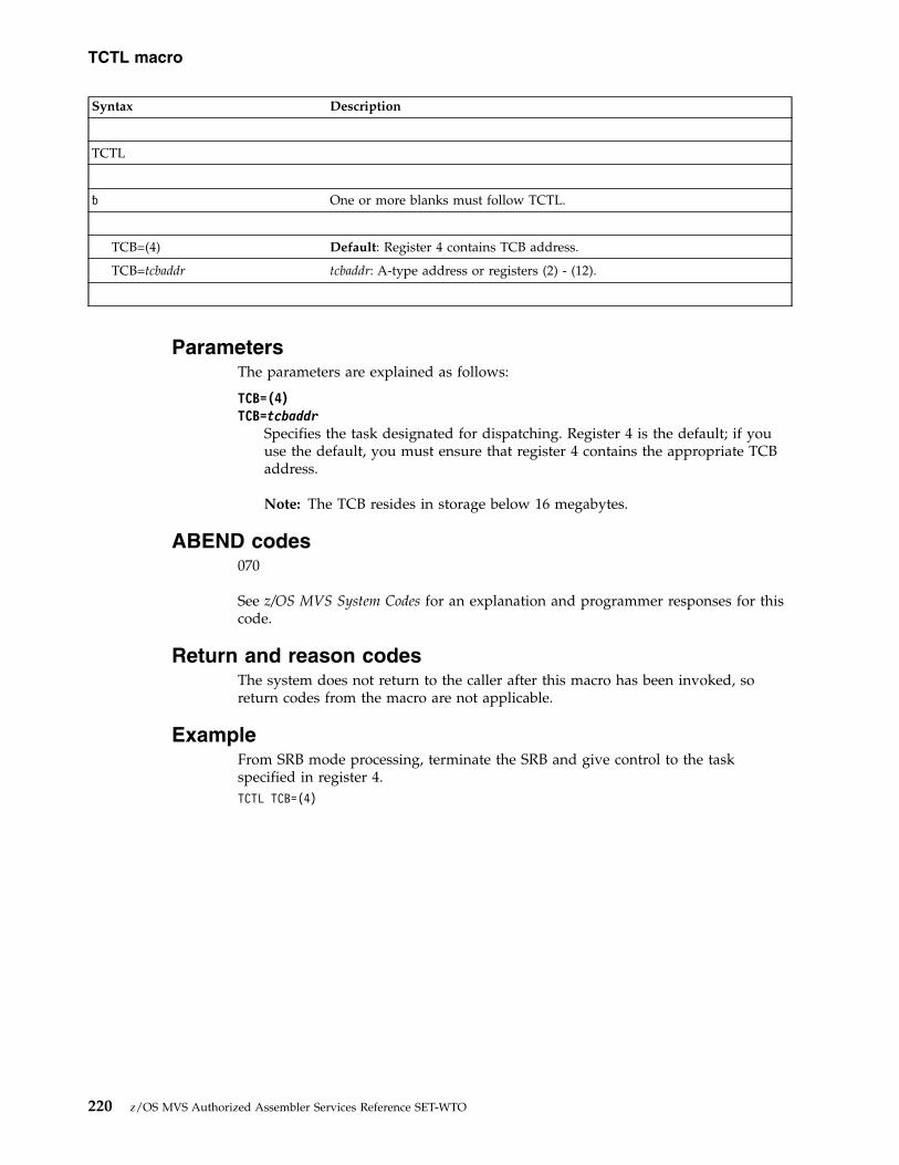
Syntax Description
TCTL
� One or more blanks must follow TCTL.
TCB=(4) Default: Register 4 contains TCB address.
TCB=tcbaddr tcbaddr: A-type address or registers (2) - (12).
ParametersThe parameters are explained as follows:
TCB=(4) TCB=tcbaddr
Specifies the task designated for dispatching. Register 4 is the default; if youuse the default, you must ensure that register 4 contains the appropriate TCBaddress.
Note: The TCB resides in storage below 16 megabytes.
ABEND codes070
See z/OS MVS System Codes for an explanation and programmer responses for thiscode.
Return and reason codesThe system does not return to the caller after this macro has been invoked, soreturn codes from the macro are not applicable.
ExampleFrom SRB mode processing, terminate the SRB and give control to the taskspecified in register 4.TCTL TCB=(4)
TCTL macro
220 z/OS MVS Authorized Assembler Services Reference SET-WTO

Chapter 21. TESTAUTH — Test authorization of caller
DescriptionThe TESTAUTH macro is used on behalf of a privileged or sensitive function toverify that its caller is appropriately authorized.
TESTAUTH supports the authorized program facility (APF) - a facility that permitsthe identification of programs that are authorized to use restricted functions. Inaddition, TESTAUTH provides the capability for testing for system key 0-7 andsupervisor state. An EUT FRR may not be in force for a caller usingBRANCH=NO.
EnvironmentThe requirements for the caller are:v When BRANCH=NO
Environmental factor RequirementMinimum authorization: Problem or supervisor state, any keyDispatchable unit mode: TaskCross memory mode: PASN=HASN=SASNAMODE: 24- or 31-bitAsc mode: PrimaryInterrupt status: Enabled for I/O and external interruptsLocks: No locks heldControl Parameters: Must be in primary address space
v When BRANCH=YES
Note: When BRANCH=YES, the caller must include the CVT mapping macro.
Environmental factor RequirementMinimum authorization: Supervisor state, any keyDispatchable unit mode: TaskCross memory mode: PASN=HASN=SASNAMODE: 24- or 31-bitAsc mode: PrimaryInterrupt status: No requirementLocks: Local lock heldControl Parameters: Must be in primary address space
Programming requirementsNone.
RestrictionsWhen using BRANCH=NO, the caller cannot have an EUT FRR established.
© Copyright IBM Corp. 1988, 2017 221

Input register informationBefore issuing the TESTAUTH macro, the caller does not have to place anyinformation into any register unless using it in register notation for a particularparameter or using it as a base register.
Output register informationWhen control returns to the caller, the GPRs contain:
RegisterContents
0-1 Used as work registers by the system
2-13 Unchanged
14 Used as a work register by the system
15 Return code
When control returns to the caller, the ARs contain:
RegisterContents
0-1 Used as work registers by the system
2-13 Unchanged
14-15 Used as work registers by the system
Performance implicationsNone.
SyntaxThe TESTAUTH macro is written as follows:
Syntax Description
name name: Symbol. Begin name in column 1.
� One or more blanks must precede TESTAUTH.
TESTAUTH
� One or more blanks must follow TESTAUTH.
FCTN=fctn fctn: Decimal digit 0 or 1 or register (2) - (12).
Default: FCTN=0 if STATE or KEY is specified. Otherwise, the default isFCTN=1.
,STATE=NO Default: STATE=NO
,STATE=YES
TESTAUTH macro
222 z/OS MVS Authorized Assembler Services Reference SET-WTO

Syntax Description
,KEY=NO Default: KEY=NO
,KEY=YES
,RBLEVEL=2 Default: RBLEVEL=2
,RBLEVEL=1 RBLEVEL is used only if KEY and/or STATE are specified; otherwiseRBLEVEL is ignored.
,BRANCH=NO Default: BRANCH=NO
,BRANCH=YES
ParametersThe parameters are explained as follows:
FCTN=fctnSpecifies the authorization of a program to be checked through APF.
FCTN=0 specifies that APF-authorization is not checked.
FCTN=1 specifies that APF-authorization is checked.
,STATE=NO ,STATE=YES
Specifies whether or not (YES or NO) a check is to be made forsupervisor/problem program state. (Supervisor state is authorized, problemprogram state is not authorized.)
,KEY=NO ,KEY=YES
Specifies whether or not (YES or NO) a check is to be made of the protectionkeys. (Protection keys 0-7 are authorized, protection keys 8-15 are notauthorized.)
Note: TESTAUTH is used to test one or more of three conditions: FCTN, STATE,or KEY. If any of the requested conditions are tested favorably, a return code ofzero is returned in register 15. If all of the requested conditions are testedunfavorably, the return code is set to 4.
,RBLEVEL=2 ,RBLEVEL=1
Specifies whether the TESTAUTH caller is a type 2, 3, or 4 SVC (RBLEVEL=2)or a type 1 SVC (RBLEVEL=1). If the TESTAUTH caller is not an SVC, specifyRBLEVEL=1. Specify RBLEVEL only if you also specify KEY and/or STATE;otherwise RBLEVEL is ignored.
,BRANCH=NO ,BRANCH=YES
Specifies a branch entry (YES) or an SVC entry (NO). If BRANCH=YES isspecified, registers 2 and 3 are modified by the TESTAUTH routine. Only SVCroutines can use BRANCH=YES.
TESTAUTH macro
Chapter 21. TESTAUTH — Test authorization of caller 223

ABEND codesNone.
Return codesWhen control is returned, register 15 contains one of the following hexadecimalreturn codes:
Table 39. Return Codes for the SAMPLE Macro
Return Code Meaning and Action
00 Meaning: Task is authorized.
Action: None.
04 Meaning: Task is not authorized.
Action: None.
Example 1Test jobstep for APF authorization.TESTAUTH FCTN=1
Example 2Test for APF authorization and supervisor state and do not check protection keys.TESTAUTH STATE=YES,KEY=NO,FCTN=1
TESTAUTH macro
224 z/OS MVS Authorized Assembler Services Reference SET-WTO

Chapter 22. TIMEUSED — Obtain accumulated CPU or vectortime
DescriptionThe TIMEUSED macro returns an 8-byte hexadecimal number in a doublewordstorage area that you specify. The number is the total CPU or vector time which isused by the current TCB or SRB until you issue the macro. The format of thenumber is time-of-day (TOD) clock or microseconds time format.
If you use the SRBSTAT save and restore services, the number includes the intervalbetween dispatch and save and between restore and TIMEUSED. It does notinclude the interval between save and restore. If you have not issued restore, thenumber includes only the interval between save and TIMEUSED.
TIMEUSED is also documented in z/OS MVS Programming: Assembler ServicesReference ABE-HSP, but without the LINKAGE=BRANCH and ENCLAVEparameters. Those parameters are only available to authorized callers.
EnvironmentThe requirements for the caller are:
Environmental factor RequirementMinimum authorization: Supervisor state and PSW key 0 when you specify
LINKAGE=BRANCH. Supervisor or problem state and anyPSW key when you specify LINKAGE=SYSTEM.
Dispatchable unit mode: Task or SRB when LINKAGE=BRANCH. Task whenLINKAGE=SYSTEM.
Cross memory mode: PASN=HASN=SASN or PASN¬=HASN¬=SASNAMODE: 31- or 64-bitASC mode: When LINKAGE=BRANCH without ECT, ENCLAVE, and
TIME_ON_CP, primary or secondary
When LINKAGE=BRANCH with ECT, ENCLAVE, orTIME_ON_CP, primary
When LINKAGE=SYSTEM, primary or access register (AR)Interrupt status: When you specify LINKAGE=BRANCH, enabled or
disabled for I/O and external interrupts; otherwise, enabledfor I/O and external interrupts.
Locks: When you specify LINKAGE=BRANCH, any locks can beheld, but none are required; otherwise, no locks can be held.
Control parameters: Must be in the primary address space or be in anaddress/data space that is addressable through a publicentry on the caller's dispatchable unit access list (DU-AL)
Programming requirementsNone.
For information about programs in 64-bit addressing mode (AMODE 64), see z/OSMVS Programming: Extended Addressability Guide.
© Copyright IBM Corp. 1988, 2017 225

RestrictionsNone.
Input register informationWhen you specify LINKAGE=BRANCH:v For ENCLAVE=SUP, register 13 must contain the address of a 36-word save area.v For TIME_ON_CP=YES, register 13 must contain the address of a 36-word save
area.v Otherwise, register 13 must contain the address of an 18-word save area.
You can provide the address by using standard linkage conventions.
Output register informationAfter the caller issues the macro, the macro might use some registers as workregisters or might change the contents of some registers. When the macro returnscontrol to the caller, the contents of these registers are not the same as they werebefore the macro was issued. If the caller depends on these registers to contain thesame value before and after they issue the macro, the caller must save theseregisters before they issue the macro. The caller restores them after the systemreturns control.
When control returns to the caller, the GPRs contain:v For ENCLAVE=SUP
64-bit Register Contents
0Time on standard CP, adjusted for currentdispatch.
1Time on IBM System z9® Integrated InformationProcessor and IBM System z10® IntegratedInformation Processor (zIIP), adjusted forcurrent dispatch
2Time zIIP on standard CP, adjusted for currentdispatch
3-13 Unchanged
14 Used as a work register by the macro
15 Return code in low 32 bits
v For TIME_ON_CP=YES
64-bit Register Contents
0 The total CPU time that is used up until youissue the macro, in TOD clock format, whetherrunning on a standard CP, System zApplication Assist Processor (zAAP), or Systemz Integrated Information Processor (zIIP)
TIMEUSED macro
226 z/OS MVS Authorized Assembler Services Reference SET-WTO

64-bit Register Contents
1The total CPU time on a standard CP used upuntil you issue the macro, in TOD clock format
2 v Unchanged if OFFLOAD_ON_CP is notspecified.
v If OFFLOAD_ON_CP is specified, the totalCPU time on a standard CP that was eligiblefor offload, up until the time you issue themacro, in TOD clock format.
3-13 Unchanged
14 Used as a work register by the macro
15 Return code in low 32 bits
v Otherwise
Register Contents
0-1 Used as work registers by the system
2-13 Unchanged
14 Used as work registers by the macro
15 Return code
v The access registers (AR) contain
Register Contents
0-1 Used as work registers by the system
2-13 Unchanged
14-15 Used as work registers by the system
Performance implicationsWhen your application uses TIMEUSED LINKAGE=SYSTEM without the CPU andVECTOR parameters (or can change to do so), consider use of the ECT parameterthat gives access to the Extract-CPU-Time (ECT) facility that is available on IBMSystem z9 or later hardware.v If your application runs on systems that support and do not support the ECT
facility, you can use the ECT=COND parameter to check for availability of thisfacility. The ECT=COND parameter adds a small extra overhead when runningon a system that does not support the ECT facility, but results in a much fasterpath when running on a system which does support the facility.
v If your application always runs on a system that supports the ECT facility, useECT=YES without specifying the LINKAGE parameter. This provides betterperformance than using LINKAGE=SYSTEM,ECT=COND.
The TIMEUSED support to use the Extract-CPU-Time facility is available on z/OSV1R8 or later systems.
Note: When you use TIMEUSED with LINKAGE=BRANCH without the CPUparameter, the system automatically uses the ECT facility when it is available,without needing a runtime check.
TIMEUSED macro
Chapter 22. TIMEUSED — Obtain accumulated CPU or vector time 227
|
|||
||
||
|||
|
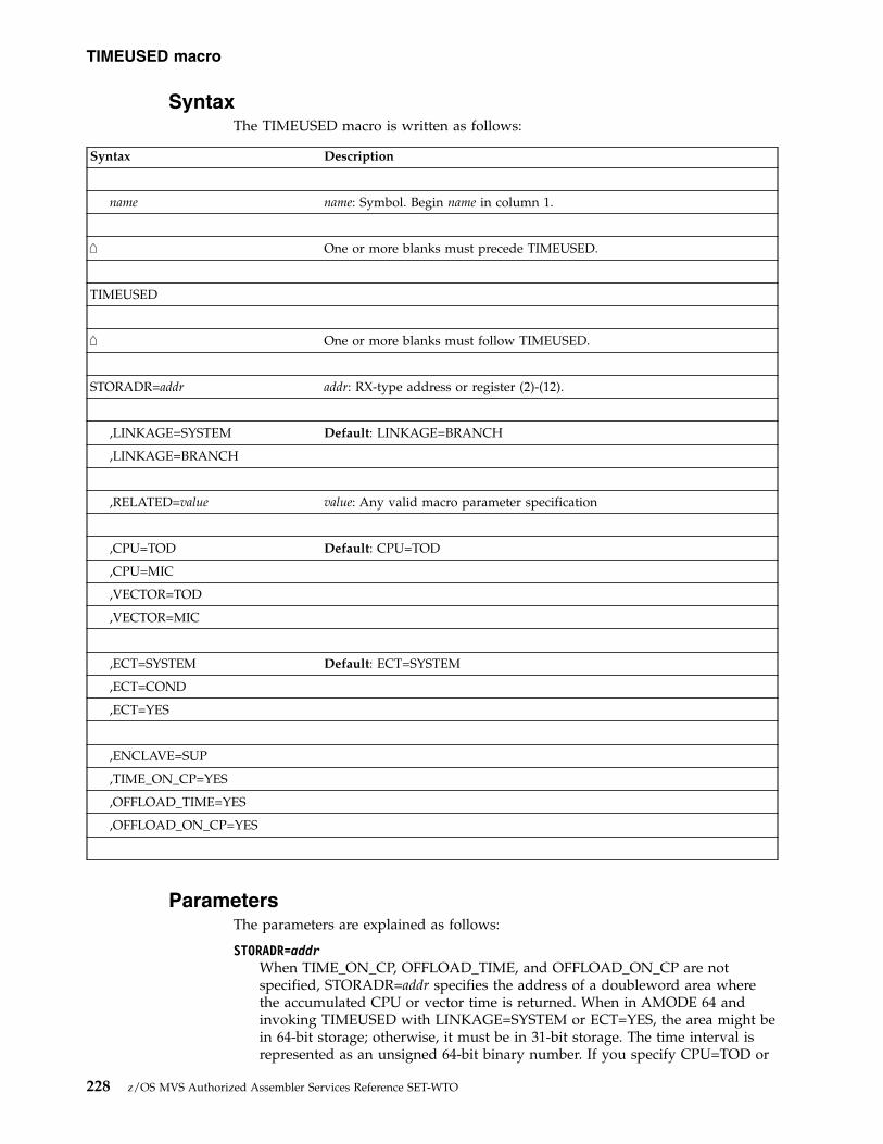
SyntaxThe TIMEUSED macro is written as follows:
Syntax Description
name name: Symbol. Begin name in column 1.
⌂ One or more blanks must precede TIMEUSED.
TIMEUSED
⌂ One or more blanks must follow TIMEUSED.
STORADR=addr addr: RX-type address or register (2)-(12).
,LINKAGE=SYSTEM Default: LINKAGE=BRANCH
,LINKAGE=BRANCH
,RELATED=value value: Any valid macro parameter specification
,CPU=TOD Default: CPU=TOD
,CPU=MIC
,VECTOR=TOD
,VECTOR=MIC
,ECT=SYSTEM Default: ECT=SYSTEM
,ECT=COND
,ECT=YES
,ENCLAVE=SUP
,TIME_ON_CP=YES
,OFFLOAD_TIME=YES
,OFFLOAD_ON_CP=YES
ParametersThe parameters are explained as follows:
STORADR=addrWhen TIME_ON_CP, OFFLOAD_TIME, and OFFLOAD_ON_CP are notspecified, STORADR=addr specifies the address of a doubleword area wherethe accumulated CPU or vector time is returned. When in AMODE 64 andinvoking TIMEUSED with LINKAGE=SYSTEM or ECT=YES, the area might bein 64-bit storage; otherwise, it must be in 31-bit storage. The time interval isrepresented as an unsigned 64-bit binary number. If you specify CPU=TOD or
TIMEUSED macro
228 z/OS MVS Authorized Assembler Services Reference SET-WTO

VECTOR=TOD, bit 51 is the low-order bit of the interval value and equivalentto 1 microsecond. If you specify CPU=MIC or VECTOR=MIC, bit 63 is thelow-order bit of the interval value and equivalent to 1 microsecond. STORADRis required except when ENCLAVE is specified. If ENCLAVE is specified,STORADR is not allowed.
When ECT=YES and one or more of TIME_ON_CP, OFFLOAD_TIME, andOFFLOAD_ON_CP are specified, STORADR=addr is required. This specifiesthe address of an 8-word area in 31-bit storage of the primary address spacewhere one or more accumulated time values are returned. It is recommendedthat the area is on a doubleword boundary. Each time interval is represented asan unsigned 64-bit binary number. Bit 51 is the low-order bit of the intervalvalue and equivalent to 1 microsecond.
On output where the return code is 0:v Words 0-1 = Total time.v Words 2-3 = Time on CP when TIME_ON_CP=YES.v Words 4-5 = Offload time (unnormalized) when OFFLOAD_TIME=YES.v Words 6-7 = Offload on CP when OFFLOAD_ON_CP=YES. Any subfield
that is not requested to be returned is unpredictable.
,LINKAGE=SYSTEM,LINKAGE=BRANCH
Specifies the type of linkage used in TIMEUSED processing.LINKAGE=BRANCH indicates branch entry. You can specify or default toLINKAGE=BRANCH if you are a key zero supervisor state program runningunder a TCB or SRB. LINKAGE=SYSTEM indicates that the linkage is bynonbranch entry.
,RELATED=valueSpecifies information used to self-document macros by “relating” functions orservices to corresponding functions or services. The format and contents of theinformation that is specified are at the discretion of the user and can be anyvalid coding values.
,CPU=TOD,CPU=MIC,VECTOR=TOD,VECTOR=MIC
Specifies that TIMEUSED return the total CPU or vector time in either TODclock format (CPU=TOD or VECTOR=TOD) or in microseconds (CPU=MIC orVECTOR=MIC). You can specify CPU=MIC or VECTOR only ifLINKAGE=SYSTEM.
,ECT=SYSTEMSpecifies that the system determines which instruction service to use. ForLINKAGE=BRANCH, the system uses the Extract CPU Time instructionservice when that service is available. For LINKAGE=SYSTEM, it will not usethe Extract CPU Time instruction service.
,ECT=CONDSpecifies that the system is conditionally to use the Extract CPU Timeinstruction service. If the service and instruction are available, the system usesthat service. Otherwise, the system uses the regular TIMEUSED service. Outputis in TOD format. Use only with LINKAGE=SYSTEM. Do not specify the CPUor VECTOR parameters. You must include the CVT, IHAECVT, and IHAPSAmapping macros.
TIMEUSED macro
Chapter 22. TIMEUSED — Obtain accumulated CPU or vector time 229

,ECT=YESSpecifies that the system is unconditionally to use the Extract CPU Timeinstruction service. You must verify that the service and instruction areavailable (running on z/OS V1R8 or later, with bit FLCFECT on in byteFLCFACL3 in macro IHAPSA). Output is in TOD format. Do not specify theCPU, VECTOR, or LINKAGE parameters. You must include the CVT,IHAECVT, and IHAPSA mapping macros.
,ENCLAVE=SUPSpecifies that the system is to return ENCLAVE time which pertains to Systemz9 Integrated Information Processor (zIIP) usage, which is adjusted for the timespent within the current dispatch. Requires LINKAGE=BRANCH.
,TIME_ON_CP=YESReturns CPU time on standard CP, in TOD clock format, for the current workunit.v When TIME_ON_CP=YES is specified without the ECT=YES parameter,
LINKAGE=BRANCH is required and ENCLAVE or ECT must not bespecified.
v When TIME_ON_CP=YES is specified with the ECT=YES parameter, theinvocation must be in task mode, requires STORADR, and can be specifiedalong with either OFFLOAD_TIME=YES or OFFLOAD_ON_CP=YES, orboth. You must include DSECTs CVT and IHAECVT. The function isavailable only if bit CVTECT1 in byte CVTOSLV8 of the CVT data area ison.
,OFFLOAD_TIME=YESReturns CPU time on offload engines, in TOD clock format, for the currenttask. This time is unnormalized (it is in the units that apply to the offloadprocessors). Requires the ECT=YES and STORADR parameters and can bespecified along with TIME_ON_CP=YES or OFFLOAD_ON_CP=YES, or both.You must include DSECTs CVT and IHAECVT. The function is available only ifbit CVTECT1 in byte CVTOSLV8 of the CVT data area is on.
,OFFLOAD_ON_CP=YESReturns CPU time on a standard CP that was eligible for offload, in TOD clockformat, for the current task.v When OFFLOAD_ON_CP=YES is specified without the ECT=YES parameter,
LINKAGE=BRANCH is required and STORADR, ENCLAVE, or ECT mustnot be specified. If the invocation is in SRB mode, no data is returned. Thefunction is available only if bit CVTOOCP in byte CVTOSLV8 of the CVTdata area is on.
v When OFFLOAD_ON_CP=YES is specified with the ECT=YES parameter,the invocation must be in task mode, requires STORADR, and can bespecified along with either TIME_ON_CP=YES or OFFLOAD_ON_CP=YES,or both. You must include DSECTs CVT and IHAECVT. The function isavailable only if bit CVTECT1 in byte CVTOSLV8 of the CVT data area ison.
Return codesWhen control returns to the caller, GPR 15 contains one of the followinghexadecimal return codes.
TIMEUSED macro
230 z/OS MVS Authorized Assembler Services Reference SET-WTO
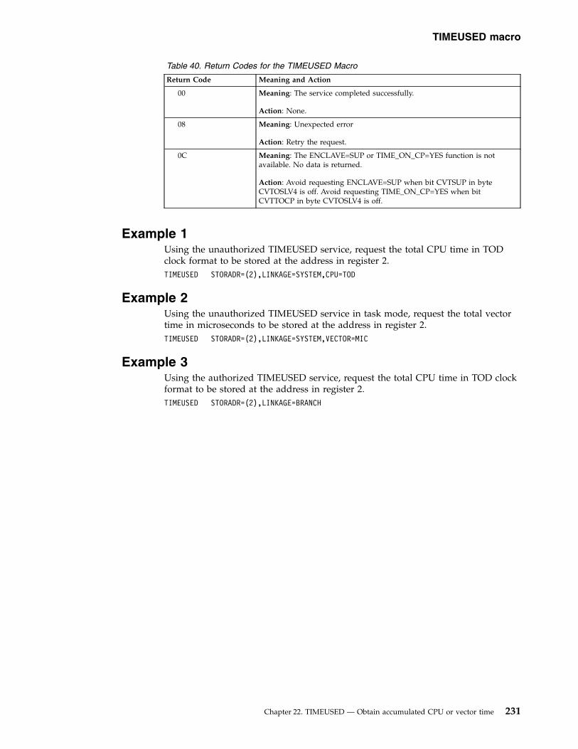
Table 40. Return Codes for the TIMEUSED Macro
Return Code Meaning and Action
00 Meaning: The service completed successfully.
Action: None.
08 Meaning: Unexpected error
Action: Retry the request.
0C Meaning: The ENCLAVE=SUP or TIME_ON_CP=YES function is notavailable. No data is returned.
Action: Avoid requesting ENCLAVE=SUP when bit CVTSUP in byteCVTOSLV4 is off. Avoid requesting TIME_ON_CP=YES when bitCVTTOCP in byte CVTOSLV4 is off.
Example 1Using the unauthorized TIMEUSED service, request the total CPU time in TODclock format to be stored at the address in register 2.TIMEUSED STORADR=(2),LINKAGE=SYSTEM,CPU=TOD
Example 2Using the unauthorized TIMEUSED service in task mode, request the total vectortime in microseconds to be stored at the address in register 2.TIMEUSED STORADR=(2),LINKAGE=SYSTEM,VECTOR=MIC
Example 3Using the authorized TIMEUSED service, request the total CPU time in TOD clockformat to be stored at the address in register 2.TIMEUSED STORADR=(2),LINKAGE=BRANCH
TIMEUSED macro
Chapter 22. TIMEUSED — Obtain accumulated CPU or vector time 231

TIMEUSED macro
232 z/OS MVS Authorized Assembler Services Reference SET-WTO

Chapter 23. T6EXIT — Type 6 exit
DescriptionThe T6EXIT macro returns control from a type 6 SVC. This exit macro can only beused in a type 6 SVC routine.
EnvironmentThe requirements for the caller are:
Environmental factor RequirementMinimum authorization: Supervisor state and PSW key 0Dispatchable unit mode: TaskCross memory mode: PASN=HASN=SASNAMODE: 24- or 31-bitASC mode: PrimaryInterrupt status: Disabled for I/O and external interruptsLocks: No locks heldControl parameters: None
Programming requirementsThe caller must include the CVT mapping macro with DSECT=YES specified.
RestrictionsNone.
Input register informationOn input, general purpose register (GPR) 1 must point to a service request block(SRB) if RETURN=SRB is specified.
Output register informationFor RETURN=CALLER, registers 0, 1, and 15 are returned from the type 6 SVCroutine to the calling program (the issuer of the SVC). For RETURN=DISPATCHand RETURN=SRB, no registers are returned to the calling program.
Performance implicationsNone.
SyntaxThe T6EXIT macro is written as follows:
Syntax Description
name name: Symbol. Begin name in column 1.
� One or more blanks must precede T6EXIT.
© Copyright IBM Corp. 1988, 2017 233

Syntax Description
T6EXIT
� One or more blanks must follow T6EXIT.
RETURN=CALLER Default: RETURN=CALLER
RETURN=DISPATCH
RETURN=SRB
ParameterThe explanation of the RETURN parameter is as follows:
RETURNSpecifies how the type 6 SVC has chosen to exit, which is one of the following:v CALLER specifies that the return is directly to the caller or issuer of the
SVC. The contents of GPRs 0, 1, and 15 at the time of the T6EXIT arereturned to the issuer of the SVC. CALLER is the default return option.
v DISPATCH specifies that the return should be to the system to dispatchother work. This function is for the use of routines that have suspended thecurrent task. When the task resumes, the issuer of the type 6 SVC receivescontrol at the instruction after the SVC.
v SRB specifies that the system should immediately dispatch an SRB. This SRBmust:– Be initialized by the type 6 SVC.– Be pointed to by register 1.– Run in the same address space as the SVC. The SRB has the same format
as an SRB dispatched through the SCHEDULE macro.
ABEND codesNone.
Return and reason codesNone.
ExampleTerminate type 6 SVC processing and return control from the type 6 SVC to thecaller of the SVC.T6EXIT RETURN=CALLER
T6EXIT macro
234 z/OS MVS Authorized Assembler Services Reference SET-WTO

Chapter 24. UCBINFO — Return information from a UCB
DescriptionUse the UCBINFO macro to obtain information from a unit control block (UCB) fora specified device. The UCBINFO macro provides the following options:
DEVCOUNTReturns a count of the UCBs for a device class or device group.
DEVINFOReturns information about a device, particularly, why the device is offline.For the base UCB of a Parallel Access Volume (PAV), DEVINFO returns thenumber of alias UCBs that are defined, and the number that are usable.Also, the DEVINFO can return an indicator in the IOSDDEVI mappingmacro reflecting whether the device is a Hyper Parallel Access Volume(HyperPAV) device.
GETCDR
Returns the Configuration Data Record (CDR) for a specific device-pathfrom the Configuration Data Table (CDT).
HYPERPAVALIASESReturns information for HyperPAV aliases that are configured in the samelogical subsystem as the input device. The HYPERPAVALIASES functionallows you to obtain selected information for each alias exposure of aParallel Access Volume (PAV) device in HyperPAV mode. All aliasexposures contained in the logical subsystem are returned in the outputPAVAREA. The data returned by this function is mapped by the mappingmacro IOSDPAVA and consists of a header and one or more entries.
PATHINFOReturns information about the device path and type of channel pathassociated with the device.
PATHMAPReturns information about the device path.
PRFXDATAObtains a copy of the UCB prefix extension segment.
PAVINFOReturns information about the alias UCBs for a Parallel Access Volume(PAV) or a Hyper Parallel Access Volume (HyperPAV).
The options of the UCBINFO macro have the same environmental specifications,programming requirements, restrictions, register information, and performanceimplications described below, except where noted in the explanations of eachoption.
© Copyright IBM Corp. 1988, 2017 235
|
||

EnvironmentThe requirements for the caller are:
Environmental factor RequirementMinimum authorization: Problem state and any PSW key. If the UCBPTR keyword is
used, Supervisor state or PSW key 0-7.
For LINKAGE=BRANCH, all of the following:
v Supervisor state with key 0
v 31-bit addressing mode
v Primary ASC mode
v Parameter list and any data areas it points to must be infixed storage or disabled reference (DREF) storage.
Dispatchable unit mode: Task or SRBCross memory mode: Any PASN, any HASN, any SASNAMODE: 24- or 31-bitASC mode: Primary or access register (AR)Interrupt status: Enabled or disabled for I/O and external interruptsLocks: The caller may hold locks, but is not required to hold anyControl parameters: Control parameters must be in the primary address space or,
for AR-mode callers, must be in an address/data space thatis addressable through a public entry on the caller'sdispatchable unit access list (DU-AL).
Programming requirementsBefore issuing the UCBINFO macro, you can issue the UCBSCAN macro to obtaineither the UCBPTR or the device number, which you must provide as input toUCBINFO. z/OS MVS Programming: Assembler Services Guide Authorized callersmust serialize (such as through pinning) the device against dynamic deletionswhen specifying any of the following:v DEVINFO with the UCBPTR parameterv GETCDR with the UCBPTR parameterv HYPERPAVALIASES with the UCBPTR parameterv PATHINFO with the UCBPTR parameterv PATHMAP with the UCB pointer in the MAPAREA field.v PRFXDATA with the UCBPTR parameterv PAVINFO with the UCBPTR parameter
See z/OS MVS Programming: Authorized Assembler Services Guide for informationabout accessing and pinning UCBs.
The caller must include the appropriate mapping macro for the UCBINFO optionbeing used:
Option Mapping Macro
DEVCOUNTNone
DEVINFOIOSDDEVI mapping macro
HYPERPAVALIASESIOSDPAVA mapping macro
UCBINFO macro
236 z/OS MVS Authorized Assembler Services Reference SET-WTO
||
|

PATHINFOIOSDPATH mapping macro
PATHMAPIOSDMAP mapping macro
PAVINFOIOSDPAVA mapping macro
PRFXDATAIOSDUPI mapping macro
RestrictionsNone.
Input register informationBefore issuing the UCBINFO macro, the caller does not have to place anyinformation into any register unless using it in register notation for a particularparameter, or using it as a base register.
Output register informationWhen control returns to the caller, the GPRs contain:
RegisterContents
0 A reason code; otherwise, used as a work register by the system
1 Used as a work register by the system
2-13 Unchanged
14 Used as a work register by the system
15 A return code
When control returns to the caller, the ARs contain:
RegisterContents
0-1 Used as work registers by the system
2-13 Unchanged
14-15 Used as work registers by the system
Performance implicationsNone.
UCBINFO DEVCOUNTUse the UCBINFO DEVCOUNT macro to obtain a count of the UCBs for a deviceclass.
SyntaxThe standard form of the DEVCOUNT option of the UCBINFO macro is written asfollows:
UCBINFO macro
Chapter 24. UCBINFO — Return information from a UCB 237
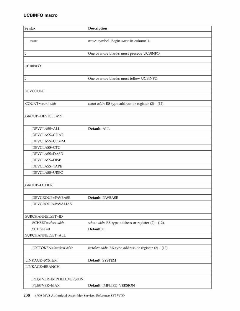
Syntax Description
name name: symbol. Begin name in column 1.
� One or more blanks must precede UCBINFO.
UCBINFO
� One or more blanks must follow UCBINFO.
DEVCOUNT
,COUNT=count addr count addr: RS-type address or register (2) - (12).
,GROUP=DEVICELASS
,DEVCLASS=ALL Default: ALL
,DEVCLASS=CHAR
,DEVCLASS=COMM
,DEVCLASS=CTC
,DEVCLASS=DASD
,DEVCLASS=DISP
,DEVCLASS=TAPE
,DEVCLASS=UREC
,GROUP=OTHER
,DEVGROUP=PAVBASE Default: PAVBASE
,DEVGROUP=PAVALIAS
,SUBCHANNELSET=ID
,SCHSET=schset addr schset addr: RS-type address or register (2) - (12).
,SCHSET=0 Default: 0
,SUBCHANNELSET=ALL
,IOCTOKEN=ioctoken addr ioctoken addr: RX-type address or register (2) - (12).
,LINKAGE=SYSTEM Default: SYSTEM
,LINKAGE=BRANCH
,PLISTVER=IMPLIED_VERSION
,PLISTVER=MAX Default: IMPLIED_VERSION
UCBINFO macro
238 z/OS MVS Authorized Assembler Services Reference SET-WTO

Syntax Description
,PLISTVER=plistver plistver: 2
,RETCODE=retcode addr retcode addr: RX-type address or register (2) - (12).
,RSNCODE=rsncode addr rsncode addr: RX-type address or register (2) - (12).
ParametersThe parameters are explained as follows:
DEVCOUNTSpecifies that the system is to return a count of the UCBs.
,COUNT=count addrSpecifies the address of the fullword field that is to receive the count.
,GROUP=DEVICECLASSGROUP specifies the grouping upon which the UCB count is based.
DEVICECLASS indicates that the UCB count is based on device classes.
,DEVICECLASS=ALL|CHAR|COMM|CTC|DASD|DISP|TAPE|URECSpecifies the device class for which the corresponding UCBs are to becounted:
ALL Counts UCBs for all device classes
CHARCounts UCBs for character reader device class
COMMCounts UCBs for communications device class
CTC Counts UCBs for channel to channel device class
DASDCounts UCBs for direct access device class
DISP Counts UCBs for display device class
TAPE Counts UCBs for tape device class
UREC Counts UCBs for unit record device class
,GROUP=OTHERGROUP specifies the grouping upon which the UCB count is based.
OTHER indicates that the UCB count is not based on device classes.
,DEVGROUP=PAVBASE,DEVGROUP=PAVALIAS
Specifies the device group for which the corresponding UCBs are to becounted.v PAVBASE, counts UCBs for Parallel Access Volume (PAV) base UCBs.v PAVALIAS, counts UCBs for Parallel Access Volume (PAV) alias UCBs.
,SUBCHANNELSET=ID,SUBCHANNELSET=ALL
UCBINFO macro
Chapter 24. UCBINFO — Return information from a UCB 239

,SUBCHANNELSET=IDIndicates the UCB count is based on one subchannel set. DEFAULT: ID
,SCHSET=schset addr,SCHSET=0
Specifies the name (RS-type), or address in register (2)-(12), of an optionalbyte input that specifies a subchannel set for which the UCBINFO requestis to be performed. DEFAULT: 0.
,SUBCHANNELSET=ALLIndicates the UCB count is based on all subchannel sets. DEFAULT: ID
,IOCTOKEN=ioctoken addrSpecifies the address of a 48-character storage area that contains the MVS I/Oconfiguration token. The caller can obtain this token by issuing the IOCINFOmacro, which is described in z/OS MVS Programming: Assembler ServicesReference ABE-HSP. If the I/O configuration token that is current whenUCBINFO is invoked does not match the token whose address is suppliedhere, the system issues a return code to the caller.
If you set the input IOCTOKEN (specified by ioctoken addr) to binary zeros,UCBINFO sets IOCTOKEN to the current I/O configuration token.
,LINKAGE=SYSTEM,LINKAGE=BRANCH
Specifies the type of call that the system is to generate:v SYSTEM: Specifies a Program Call (PC)v BRANCH: Specifies a Branch entry
LINKAGE=BRANCH is intended for performance-sensitive programs.
,PLISTVER=IMPLIED_VERSION,PLISTVER=MAX,PLISTVER=plistver
Specifies the version of the macro. PLISTVER determines which parameter listthe system generates. PLISTVER is an optional input parameter on all forms ofthe macro, including the list form. When using PLISTVER, specify it on allmacro forms used for a request and with the same value on all of the macroforms. The values are:v IMPLIED_VERSION, which is the lowest version that allows all parameters
specified on the request to be processed. If you omit the PLISTVERparameter, IMPLIED_VERSION is the default.
v MAX, if you want the parameter list to be the largest size currently possible.This size might grow from release to release and affect the amount ofstorage that your program needs.If you can tolerate the size change, IBM recommends that you alwaysspecify PLISTVER=MAX on the list form of the macro. Specifying MAXensures that the list-form parameter list is always long enough to hold allthe parameters you might specify on the execute form; in this way, MAXensures that the parameter list does not overwrite nearby storage.
v 2, if you use the currently available parameters.
To code, specify in this input parameter one of the following:v IMPLIED_VERSIONv MAXv A decimal value of 2.
UCBINFO macro
240 z/OS MVS Authorized Assembler Services Reference SET-WTO
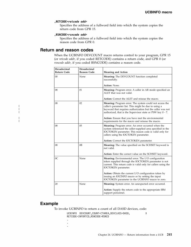
,RETCODE=retcode addrSpecifies the address of a fullword field into which the system copies thereturn code from GPR 15.
,RSNCODE=rsncode addrSpecifies the address of a fullword field into which the system copies thereason code from GPR 0.
Return and reason codesWhen the UCBINFO DEVCOUNT macro returns control to your program, GPR 15(or retcode addr, if you coded RETCODE) contains a return code, and GPR 0 (orrsncode addr, if you coded RSNCODE) contains a reason code.
HexadecimalReturn Code
HexadecimalReason Code Meaning and Action
00 None Meaning: The DEVCOUNT function completedsuccessfully.
Action: None.
08 01 Meaning: Program error. A caller in AR mode specified anALET that was not valid.
Action: Correct the ALET and reissue the macro.
08 02 Meaning: Program error. The system could not access thecaller's parameter list. This might be due to using akeyword that requires authorization but the caller was notauthorized, that is the Supervisor state or PSW key 0 - 7.
Action: Ensure that you have met the environmentalrequirements for the macro and reissue the macro.
08 05 Meaning: Program error. An error occurred when thesystem referenced the caller-supplied area specified in theIOCTOKEN parameter. This reason code is valid only forcallers using the IOCTOKEN parameter.
Action: Correct the IOCTOKEN parameter.
08 0B Meaning: The value specified on the SCHSET keyword isnot valid.
Action: Enter the correct value on the SCHSET keyword.
0C None Meaning: Environmental error. The I/O configurationtoken supplied through the IOCTOKEN parameter is notcurrent. This return code is valid only for callers using theIOCTOKEN parameter.
Action: Obtain the current I/O configuration token byissuing an IOCINFO macro or by setting the inputIOCTOKEN parameter in the UCBINFO macro to zero.
20 None Meaning: System error. An unexpected error occurred.
Action: Supply the return code to the appropriate IBMsupport personnel.
ExampleTo invoke UCBINFO to return a count of all DASD devices, code:
UCBINFO DEVCOUNT,COUNT=CTAREA,DEVCLASS=DASD, XRETCODE=INFORTCD,RSNCODE=RSNCD...
UCBINFO macro
Chapter 24. UCBINFO — Return information from a UCB 241
|||
||
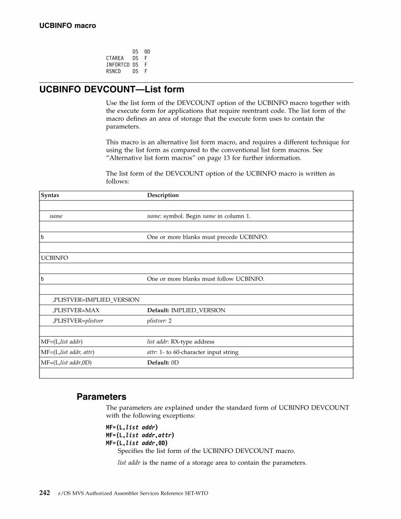
DS 0DCTAREA DS FINFORTCD DS FRSNCD DS F
UCBINFO DEVCOUNT—List formUse the list form of the DEVCOUNT option of the UCBINFO macro together withthe execute form for applications that require reentrant code. The list form of themacro defines an area of storage that the execute form uses to contain theparameters.
This macro is an alternative list form macro, and requires a different technique forusing the list form as compared to the conventional list form macros. See“Alternative list form macros” on page 13 for further information.
The list form of the DEVCOUNT option of the UCBINFO macro is written asfollows:
Syntax Description
name name: symbol. Begin name in column 1.
� One or more blanks must precede UCBINFO.
UCBINFO
� One or more blanks must follow UCBINFO.
,PLISTVER=IMPLIED_VERSION
,PLISTVER=MAX Default: IMPLIED_VERSION
,PLISTVER=plistver plistver: 2
MF=(L,list addr) list addr: RX-type address
MF=(L,list addr, attr) attr: 1- to 60-character input string
MF=(L,list addr,0D) Default: 0D
ParametersThe parameters are explained under the standard form of UCBINFO DEVCOUNTwith the following exceptions:
MF=(L,list addr)MF=(L,list addr,attr)MF=(L,list addr,0D)
Specifies the list form of the UCBINFO DEVCOUNT macro.
list addr is the name of a storage area to contain the parameters.
UCBINFO macro
242 z/OS MVS Authorized Assembler Services Reference SET-WTO

attr is an optional 1- to 60-character input string, which can contain any valuethat is valid on an assembler DS pseudo-op. You can use this parameter toforce boundary alignment of the parameter list. If you do not code attr, thesystem provides a value of 0D, which forces the parameter list to adoubleword boundary.
UCBINFO DEVCOUNT—Execute formUse the execute form of the DEVCOUNT option of the UCBINFO macro togetherwith the list form of the macro for applications that require reentrant code. Theexecute form of the macro stores the parameters into the storage area defined bythe list form.
The execute form of the DEVCOUNT option of the UCBINFO macro is written asfollows:
Syntax Description
name name: symbol. Begin name in column 1.
� One or more blanks must precede UCBINFO.
UCBINFO
� One or more blanks must follow UCBINFO.
DEVCOUNT
,COUNT=count addr count addr: RS-type address or register (2) - (12).
,GROUP=DEVICELASS
,DEVCLASS=ALL Default: ALL
,DEVCLASS=CHAR
,DEVCLASS=COMM
,DEVCLASS=CTC
,DEVCLASS=DASD
,DEVCLASS=DISP
,DEVCLASS=TAPE
,DEVCLASS=UREC
,GROUP=OTHER
,DEVGROUP=PAVBASE Default: PAVBASE
,SUBCHANNELSET=ID
UCBINFO macro
Chapter 24. UCBINFO — Return information from a UCB 243

Syntax Description
,SCHSET=schset addr schset addr: RS-type address or register (2) - (12).
,SCHSET=0 Default: 0
,SUBCHANNELSET=ALL
,IOCTOKEN=ioctoken addr ioctoken addr: RX-type address or register (2) - (12).
,LINKAGE=SYSTEM Default: SYSTEM
,LINKAGE=BRANCH
,PLISTVER=IMPLIED_VERSION
,PLISTVER=MAX Default: IMPLIED_VERSION
,PLISTVER=plistver plistver: 2
,RETCODE=retcode addr retcode addr: RX-type address or register (2) - (12).
,RSNCODE=rsncode addr rsncode addr: RX-type address or register (2) - (12).
,MF=(E,list addr) list addr: RX-type address or address in register (2) - (12).
,MF=(E,list addr,COMPLETE) Default: COMPLETE
ParametersThe parameters are explained under the standard form of UCBINFO DEVCOUNTwith the following exceptions:
,MF=(E,list addr),MF=(E,list addr,COMPLETE)
Specifies the execute form of the UCBINFO DEVCOUNT macro.
list addr specifies the area that the system uses to contain the parameters.
COMPLETE, which is the default, specifies that the macro is to check forrequired parameters and supply defaults for omitted optional parameters.
UCBINFO DEVINFOUse the UCBINFO DEVINFO macro to obtain information about a device,specifically, reasons why the device is offline.
If using a UCB copy, the user must pass the device number in DEVN. The callercan obtain the address of the UCB common segment by a UCBPTR parameter on aUCBLOOK macro. The use of UCBPTR is restricted to callers in Supervisor state orPSW key 0 - 7.
SyntaxThe standard form of the DEVINFO option of the UCBINFO macro is written asfollows:
UCBINFO macro
244 z/OS MVS Authorized Assembler Services Reference SET-WTO

Syntax Description
name name: symbol. Begin name in column 1.
� One or more blanks must precede UCBINFO.
UCBINFO
� One or more blanks must follow UCBINFO.
DEVINFO
,DEVIAREA=deviarea addr deviarea addr: RX-type address or register (2) - (12).
,DEVN=devn addr devn addr: RS-type address or register (2) - (12).
Note: Specify either DEVN or UCBPTR, but not both.
,SCHSET=schset addr schset addr: RS-type address or register (2) - (12).
,SCHSET=0 Default: 0
,UCBPTR=ucbptr addr ucbptr addr: RS-type address.
Note: Specify either DEVN or UCBPTR, but not both.
,IOCTOKEN=ioctoken addr ioctoken addr: RX-type address or register (2) - (12).
,LINKAGE=SYSTEM Default: SYSTEM
,LINKAGE=BRANCH
,PLISTVER=IMPLIED_VERSION
,PLISTVER=MAX Default: IMPLIED_VERSION
,PLISTVER=plistver plistver: 2
,RETCODE=retcode addr retcode addr: RX-type address or register (2) - (12).
,RSNCODE=rsncode addr rsncode addr: RX-type address or register (2) - (12).
ParametersThe parameters are explained as follows:
DEVINFOSpecifies that the system is to return information about the specified device.
UCBINFO macro
Chapter 24. UCBINFO — Return information from a UCB 245
|
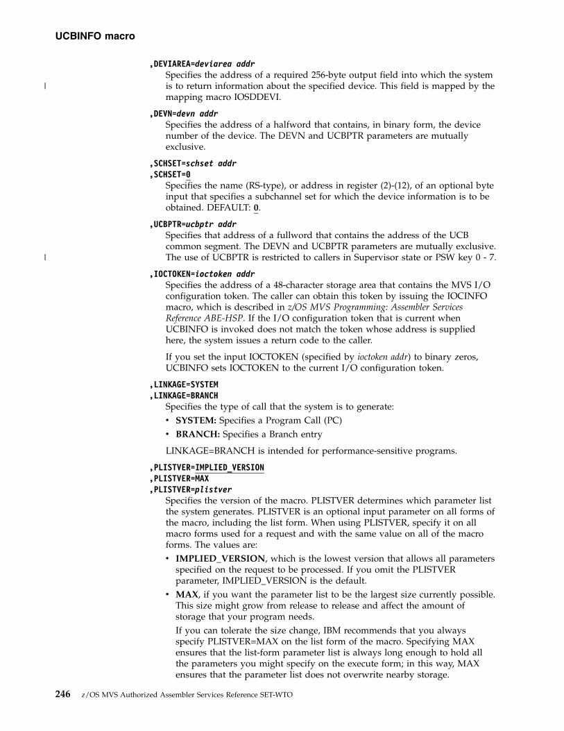
,DEVIAREA=deviarea addrSpecifies the address of a required 256-byte output field into which the systemis to return information about the specified device. This field is mapped by themapping macro IOSDDEVI.
,DEVN=devn addrSpecifies the address of a halfword that contains, in binary form, the devicenumber of the device. The DEVN and UCBPTR parameters are mutuallyexclusive.
,SCHSET=schset addr,SCHSET=0
Specifies the name (RS-type), or address in register (2)-(12), of an optional byteinput that specifies a subchannel set for which the device information is to beobtained. DEFAULT: 0.
,UCBPTR=ucbptr addrSpecifies that address of a fullword that contains the address of the UCBcommon segment. The DEVN and UCBPTR parameters are mutually exclusive.The use of UCBPTR is restricted to callers in Supervisor state or PSW key 0 - 7.
,IOCTOKEN=ioctoken addrSpecifies the address of a 48-character storage area that contains the MVS I/Oconfiguration token. The caller can obtain this token by issuing the IOCINFOmacro, which is described in z/OS MVS Programming: Assembler ServicesReference ABE-HSP. If the I/O configuration token that is current whenUCBINFO is invoked does not match the token whose address is suppliedhere, the system issues a return code to the caller.
If you set the input IOCTOKEN (specified by ioctoken addr) to binary zeros,UCBINFO sets IOCTOKEN to the current I/O configuration token.
,LINKAGE=SYSTEM,LINKAGE=BRANCH
Specifies the type of call that the system is to generate:v SYSTEM: Specifies a Program Call (PC)v BRANCH: Specifies a Branch entry
LINKAGE=BRANCH is intended for performance-sensitive programs.
,PLISTVER=IMPLIED_VERSION,PLISTVER=MAX,PLISTVER=plistver
Specifies the version of the macro. PLISTVER determines which parameter listthe system generates. PLISTVER is an optional input parameter on all forms ofthe macro, including the list form. When using PLISTVER, specify it on allmacro forms used for a request and with the same value on all of the macroforms. The values are:v IMPLIED_VERSION, which is the lowest version that allows all parameters
specified on the request to be processed. If you omit the PLISTVERparameter, IMPLIED_VERSION is the default.
v MAX, if you want the parameter list to be the largest size currently possible.This size might grow from release to release and affect the amount ofstorage that your program needs.If you can tolerate the size change, IBM recommends that you alwaysspecify PLISTVER=MAX on the list form of the macro. Specifying MAXensures that the list-form parameter list is always long enough to hold allthe parameters you might specify on the execute form; in this way, MAXensures that the parameter list does not overwrite nearby storage.
UCBINFO macro
246 z/OS MVS Authorized Assembler Services Reference SET-WTO
|
|

v 2, if you use the currently available parameters.
To code, specify in this input parameter one of the following:v IMPLIED_VERSIONv MAXv A decimal value of 2
,RETCODE=retcode addrSpecifies the address of a fullword field into which the system copies thereturn code from GPR 15.
,RSNCODE=rsncode addrSpecifies the address of a fullword field into which the system copies thereason code from GPR 0.
Return and reason codesWhen the UCBINFO DEVINFO macro returns control to your program, GPR 15 (orretcode addr, if you coded RETCODE) contains a return code, and GPR 0 (or rsncodeaddr, if you coded RSNCODE) contains a reason code.
Hexadecimal ReturnCode
Hexadecimal ReasonCode
Meaning and Action
00 None Meaning: The DEVINFO function completedsuccessfully.
Action: None.
04 None Meaning: Program error. No UCB exists for thedevice number specified in the DEVN parameter.
Action: Correct the device number and reissuethe macro.
08 01 Meaning: Program error. A caller in AR modespecified an ALET that was not valid.
Action: Correct the ALET and reissue the macro.
08 02 Meaning: Program error. An error occurred whenthe system tried to access the caller's parameterlist. This might be due to using a keyword thatrequires authorization but the caller was notauthorized, that is the Supervisor state or PSWkey 0 - 7.
Action: Ensure that you have met theenvironmental requirements for the macro, andreissue the macro.
08 03 Meaning: Program error. The UCB addressprovided by the caller does not represent a validUCB.
Action: Correct the UCB address and reissue themacro.
08 05 Meaning: Program error. An error occurred whenthe system referenced the caller-supplied areaspecified in the IOCTOKEN parameter. Thisreason code is valid only for callers using theIOCTOKEN parameter.
Action: Correct the IOCTOKEN parameter.
UCBINFO macro
Chapter 24. UCBINFO — Return information from a UCB 247
||||
|||

Hexadecimal ReturnCode
Hexadecimal ReasonCode
Meaning and Action
08 09 Meaning: Program error. An error occurred whenthe system attempted to reference the areaspecified by the DEVIAREA parameter.
Action: Correct the address specified on theDEVIAREA parameter and reissue the macro.
08 0B Meaning: The value specified on the SCHSETkeyword is not valid.
Action: Enter a valid value.
0C None Meaning: Environmental error. The I/Oconfiguration token supplied through theIOCTOKEN parameter is not current. This returncode is valid only for callers using theIOCTOKEN parameter.
Action: Obtain the current I/O configurationtoken by issuing an IOCINFO macro or bysetting the input IOCTOKEN parameter in theUCBINFO macro to zero.
20 None Meaning: System error. An unexpected erroroccurred.
Action: Supply the return code to the appropriateIBM support personnel.
28 None Meaning: Program error. The device number orUCB address provided by the caller represents analias UCB of a parallel access volume. Forinformation about a parallel access volume, thecaller must specify the base device number orbase UCB.
Action: Correct the DEVN or UCBPTR parameterand reissue the macro.
ExampleTo invoke UCBINFO to return device information, code:
UCBINFO DEVINFO,DEVIAREA=INFOAREA,DEVN=DEVNUM, XRETCODE=INFORTCD...
DS 0DINFOAREA DS CL256INFORTCD DS FDEVNUM DS H
UCBINFO DEVINFO - List formUse the list form of the DEVINFO option of the UCBINFO macro together with theexecute form for applications that require reentrant code. The list form of themacro defines an area of storage that the execute form uses to contain theparameters.
This macro is an alternative list form macro, and requires a different technique forusing the list form as compared to the conventional list form macros. See“Alternative list form macros” on page 13 for further information.
UCBINFO macro
248 z/OS MVS Authorized Assembler Services Reference SET-WTO
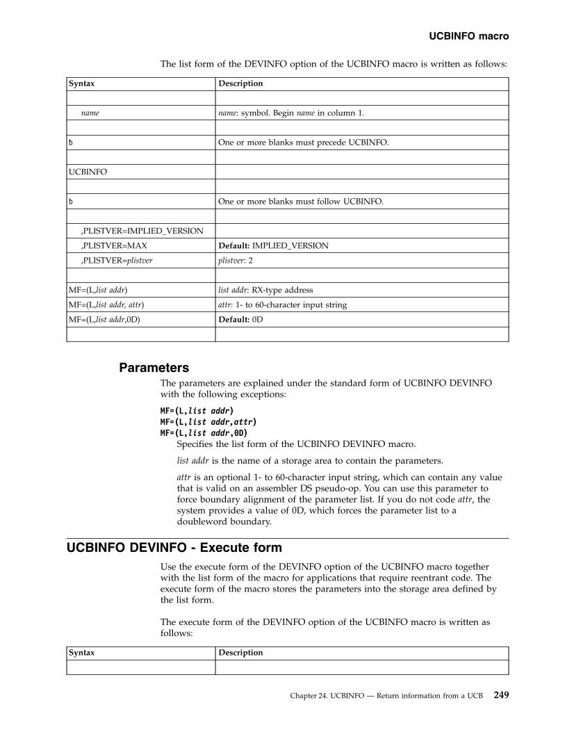
The list form of the DEVINFO option of the UCBINFO macro is written as follows:
Syntax Description
name name: symbol. Begin name in column 1.
� One or more blanks must precede UCBINFO.
UCBINFO
� One or more blanks must follow UCBINFO.
,PLISTVER=IMPLIED_VERSION
,PLISTVER=MAX Default: IMPLIED_VERSION
,PLISTVER=plistver plistver: 2
MF=(L,list addr) list addr: RX-type address
MF=(L,list addr, attr) attr: 1- to 60-character input string
MF=(L,list addr,0D) Default: 0D
ParametersThe parameters are explained under the standard form of UCBINFO DEVINFOwith the following exceptions:
MF=(L,list addr)MF=(L,list addr,attr)MF=(L,list addr,0D)
Specifies the list form of the UCBINFO DEVINFO macro.
list addr is the name of a storage area to contain the parameters.
attr is an optional 1- to 60-character input string, which can contain any valuethat is valid on an assembler DS pseudo-op. You can use this parameter toforce boundary alignment of the parameter list. If you do not code attr, thesystem provides a value of 0D, which forces the parameter list to adoubleword boundary.
UCBINFO DEVINFO - Execute formUse the execute form of the DEVINFO option of the UCBINFO macro togetherwith the list form of the macro for applications that require reentrant code. Theexecute form of the macro stores the parameters into the storage area defined bythe list form.
The execute form of the DEVINFO option of the UCBINFO macro is written asfollows:
Syntax Description
UCBINFO macro
Chapter 24. UCBINFO — Return information from a UCB 249

Syntax Description
name name: symbol. Begin name in column 1.
� One or more blanks must precede UCBINFO.
UCBINFO
� One or more blanks must follow UCBINFO.
DEVINFO
,DEVIAREA=deviarea addr deviarea addr: RX-type address or register (2) - (12).
,DEVN=devn addr devn addr: RS-type address or register (2) - (12).
Note: Specify either DEVN or UCBPTR, but not both.
,SCHSET=schset addr schset addr RS-type address or register (2) - (12).
,SCHSET=0 Default: 0
,UCBPTR=ucbptr addr ucbptr addr: RS-type address.
Note: Specify either DEVN or UCBPTR, but not both.
,IOCTOKEN=ioctoken addr ioctoken addr: RX-type address or register (2) - (12).
,LINKAGE=SYSTEM Default: SYSTEM
,LINKAGE=BRANCH
,PLISTVER=IMPLIED_VERSION
,PLISTVER=MAX Default: IMPLIED_VERSION
,PLISTVER=plistver plistver: 2
,RETCODE=retcode addr retcode addr: RX-type address or register (2) - (12).
,RSNCODE=rsncode addr rsncode addr: RX-type address or register (2) - (12).
,MF=(E,list addr) list addr: RX-type address or address in register (2) - (12).
,MF=(E,list addr,COMPLETE) Default: COMPLETE
UCBINFO macro
250 z/OS MVS Authorized Assembler Services Reference SET-WTO

ParametersThe parameters are explained under the standard form of UCBINFO DEVINFOwith the following exceptions:
,MF=(E,list addr),MF=(E,list addr,COMPLETE)
Specifies the execute form of the UCBINFO DEVINFO macro.
list addr specifies the area that the system uses to contain the parameters.
COMPLETE, which is the default, specifies that the macro is to check forrequired parameters and supply defaults for omitted optional parameters.
UCBINFO GETCDRUse the UCBINFO GETCDR macro to get a Configuration Data Record (CDR) for agiven device and path from the Configuration Data Table (CDT).
If using a UCB copy, the user must pass the device number in DEVN. The callercan obtain the address of the UCB common segment by a UCBPTR parameter on aUCBLOOK macro. The use of UCBPTR is restricted to callers in Supervisor state orPSW key 0 - 7.
SyntaxThe standard form of the GETCDR option of the UCBINFO macro is written asfollows:
Syntax Description
name name: symbol. Begin name in column 1.
� One or more blanks must precede UCBINFO.
UCBINFO
� One or more blanks must follow UCBINFO.
GETCDR
,DEVN=devn addr devn addr: RS-type address or register (2) - (12).
Note: Specify either DEVN or UCBPTR, but not both.
,SCHSET=schset addr schset addr: RS-type address or register (2) - (12).
,SCHSET=0 Default: 0
,UCBPTR=ucbptr addr ucbptr addr: RS-type address.
Note: Specify either DEVN or UCBPTR, but not both.
,PATHMASK=pathmask addr pathmask addr: RS-type address or register (2) - (12).
UCBINFO macro
Chapter 24. UCBINFO — Return information from a UCB 251
|
||
||||
|
||
|||
||
||
||
||
||
||
||
||
||
||
||
||
|
||
||
||
||
||
|
||
||

Syntax Description
,PATHMASK=0 Default: 0
,CDRAREA=cdrarea addr cdrarea addr: RS-type address or register (2) - (12).
,CDRLEN=cdrlen addr cdrlen addr: RS-type address or register (2) - (12).
,IOCTOKEN=ioctoken addr ioctoken addr: RX-type address or register (2) - (12).
,LINKAGE=SYSTEM Default: SYSTEM
,LINKAGE=BRANCH
,PLISTVER=IMPLIED_VERSION
,PLISTVER=MAX Default: IMPLIED_VERSION
,PLISTVER=plistver plistver: 2
,RETCODE=retcode addr retcode addr: RX-type address or register (2) - (12).
,RSNCODE=rsncode addr rsncode addr: RX-type address or register (2) - (12).
ParametersThe parameters are explained as follows:
,DEVN=devn addrSpecifies the name (RS-type), or address in register (2)-(12), of a halfword inputwhich specifies the device number in binary of the device whose CDR is to beretrieved.
,SCHSET=schset addr,SCHSET=0
Specifies the name (RS-type), or address in register (2)-(12), of an optional byteinput that specifies a subchannel set for which the device information is to beobtained. DEFAULT: 0.
,UCBPTR=ucbptr addrSpecifies the name (RS-type), or address in register (2)-(12), of a 4 byte inputthat contains the address of the UCB common segment whose CDR is to beretrieved. The DEVN and UCBPTR parameters are mutually exclusive. The useof UCBPTR is restricted to callers in Supervisor state or PSW key 0 - 7.
,PATHMASK=pathmask addr,PATHMASK=0
Specifies the name (RS-type), or address in register (2)-(12), of an optional 8 bitinput that contains the path mask of the device-path whose CDR is to beretrieved. This path mask maps to the UCBCHPID array. Only one bit can beset in the path mask. If the PATHMASK parameter is not specified, or is a 0, aCDR corresponding to the specified device and a path to that device isretrieved. DEFAULT: 0.
UCBINFO macro
252 z/OS MVS Authorized Assembler Services Reference SET-WTO
||
||
||
||
||
||
||
||
||
||
||
||
||
||
||
||
||
||
||
|||
|
|
||||
|||||
|||||
||||||||

,CDRAREA=cdrarea addrThis parameter is a required output and specifies the name (RS-type), oraddress in register (2)-(12), of the work area which is to receive a copy of theCDR for the requested device-path. The caller must specify the CDRLENkeyword to indicate the length of the CDRAREA.
,CDRLEN=cdrlen addrSpecifies the name (RS-type), or address in register (2)-(12), of a requiredfullword input variable which specifies the length of the CDRAREA.
,IOCTOKEN=ioctoken addrSpecifies the address of a 48-character storage area that contains the MVS I/Oconfiguration token. The caller can obtain this token by issuing the IOCINFOmacro, which is described in z/OS MVS Programming: Assembler ServicesReference ABE-HSP. If the I/O configuration token that is current whenUCBINFO is invoked does not match the token whose address is suppliedhere, the system issues a return code to the caller.
If you set the input IOCTOKEN (specified by ioctoken addr) to binary zeros,UCBINFO sets IOCTOKEN to the current I/O configuration token.
,LINKAGE=SYSTEM,LINKAGE=BRANCH
Specifies the type of call that the system is to generate:v SYSTEM: Specifies a Program Call (PC)v BRANCH: Specifies a Branch entry
LINKAGE=BRANCH is intended for performance-sensitive programs.
,PLISTVER=IMPLIED_VERSION,PLISTVER=MAX,PLISTVER=plistver
Specifies the version of the macro. PLISTVER determines which parameter listthe system generates. PLISTVER is an optional input parameter on all forms ofthe macro, including the list form. When using PLISTVER, specify it on allmacro forms used for a request and with the same value on all of the macroforms. The values are:v IMPLIED_VERSION, which is the lowest version that allows all parameters
specified on the request to be processed. If you omit the PLISTVERparameter, IMPLIED_VERSION is the default.
v MAX, if you want the parameter list to be the largest size currently possible.This size might grow from release to release and affect the amount ofstorage that your program needs.If you can tolerate the size change, IBM recommends that you alwaysspecify PLISTVER=MAX on the list form of the macro. Specifying MAXensures that the list-form parameter list is always long enough to hold allthe parameters you might specify on the execute form; in this way, MAXensures that the parameter list does not overwrite nearby storage.
v 2, if you use the currently available parameters.
To code, specify in this input parameter one of the following:v IMPLIED_VERSIONv MAXv A decimal value of 2
,RETCODE=retcode addrSpecifies the address of a fullword field into which the system copies thereturn code from GPR 15.
UCBINFO macro
Chapter 24. UCBINFO — Return information from a UCB 253
|||||
|||
|||||||
||
|||
|
|
|
||||||||
|||
|||
|||||
|
|
|
|
|
|||
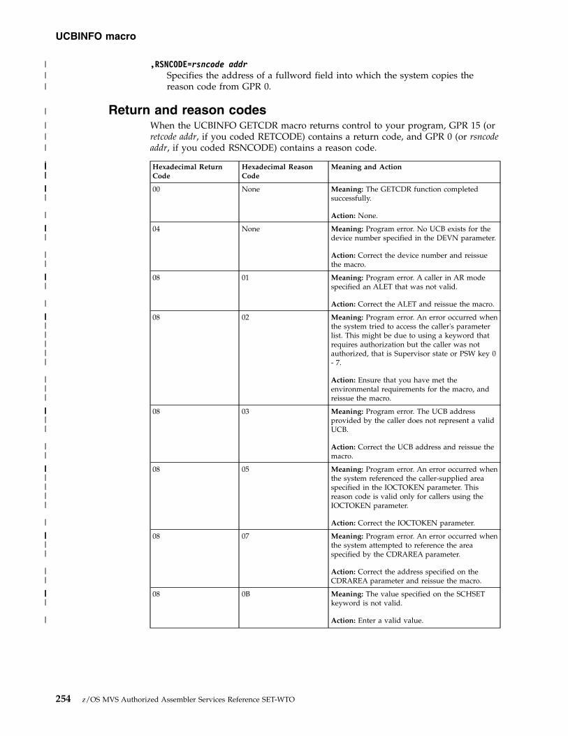
,RSNCODE=rsncode addrSpecifies the address of a fullword field into which the system copies thereason code from GPR 0.
Return and reason codesWhen the UCBINFO GETCDR macro returns control to your program, GPR 15 (orretcode addr, if you coded RETCODE) contains a return code, and GPR 0 (or rsncodeaddr, if you coded RSNCODE) contains a reason code.
Hexadecimal ReturnCode
Hexadecimal ReasonCode
Meaning and Action
00 None Meaning: The GETCDR function completedsuccessfully.
Action: None.
04 None Meaning: Program error. No UCB exists for thedevice number specified in the DEVN parameter.
Action: Correct the device number and reissuethe macro.
08 01 Meaning: Program error. A caller in AR modespecified an ALET that was not valid.
Action: Correct the ALET and reissue the macro.
08 02 Meaning: Program error. An error occurred whenthe system tried to access the caller's parameterlist. This might be due to using a keyword thatrequires authorization but the caller was notauthorized, that is Supervisor state or PSW key 0- 7.
Action: Ensure that you have met theenvironmental requirements for the macro, andreissue the macro.
08 03 Meaning: Program error. The UCB addressprovided by the caller does not represent a validUCB.
Action: Correct the UCB address and reissue themacro.
08 05 Meaning: Program error. An error occurred whenthe system referenced the caller-supplied areaspecified in the IOCTOKEN parameter. Thisreason code is valid only for callers using theIOCTOKEN parameter.
Action: Correct the IOCTOKEN parameter.
08 07 Meaning: Program error. An error occurred whenthe system attempted to reference the areaspecified by the CDRAREA parameter.
Action: Correct the address specified on theCDRAREA parameter and reissue the macro.
08 0B Meaning: The value specified on the SCHSETkeyword is not valid.
Action: Enter a valid value.
UCBINFO macro
254 z/OS MVS Authorized Assembler Services Reference SET-WTO
|||
|
|||
||||||
||||
|
||||
||
||||
|
||||||||
|||
|||||
||
|||||||
|
|||||
||
||||
|

Hexadecimal ReturnCode
Hexadecimal ReasonCode
Meaning and Action
0C None Meaning: Environmental error. The I/Oconfiguration token supplied through theIOCTOKEN parameter is not current. This returncode is valid only for callers using theIOCTOKEN parameter.
Action: Obtain the current I/O configurationtoken by issuing an IOCINFO macro or bysetting the input IOCTOKEN parameter in theUCBINFO macro to zero.
14 None Meaning: The CDR was not retrieved. Therequested CDR was not found in the CDT.
Action: None.
20 None Meaning: System error. An unexpected erroroccurred.
Action: Supply the return code to the appropriateIBM support personnel.
ExampleTo invoke UCBINFO to return a CDR for a device and path, code:
UCBINFO GETCDR,DEVN=DEVNUM, XPATHMASK=PATHMASK,CDRAREA=INFOAREA, XCDRLEN=AREALEN,RETCODE=INFORTCD
.
.
.DS 0D
DEVNUM DS HPATHMASK DS XINFOAREA DS CL256AREALEN DS FINFORTCD DS F
UCBINFO GETCDR - List formUse the list form of the GETCDR option of the UCBINFO macro together with theexecute form for applications that require reentrant code. The list form of themacro defines an area of storage that the execute form uses to contain theparameters.
This macro is an alternative list form macro, and requires a different technique forusing the list form as compared to the conventional list form macros. See“Alternative list form macros” on page 13 for further information.
The list form of the GETCDR option of the UCBINFO macro is written as follows:
Syntax Description
name name: symbol. Begin name in column 1.
� One or more blanks must precede UCBINFO.
UCBINFO
UCBINFO macro
Chapter 24. UCBINFO — Return information from a UCB 255
|||||
|||||||
||||
||||
|
||||
|||
|
|
||||||||||||
||
||||
|||
|
|||
||
||
||
||
||
||

Syntax Description
� One or more blanks must follow UCBINFO.
GETCDR
,PLISTVER=IMPLIED_VERSION
,PLISTVER=MAX Default: IMPLIED_VERSION
,PLISTVER=plistver plistver: 2
MF=(L,list addr) list addr: RX-type address
MF=(L,list addr, attr) attr: 1- to 60-character input string
MF=(L,list addr,0D) Default: 0D
ParametersThe parameters are explained under the standard form of UCBINFO GETCDRwith the following exceptions:
MF=(L,list addr)MF=(L,list addr,attr)MF=(L,list addr,0D)
Specifies the list form of the UCBINFO GETCDR macro.
list addr is the name of a storage area to contain the parameters.
attr is an optional 1- to 60-character input string, which can contain any valuethat is valid on an assembler DS pseudo-op. You can use this parameter toforce boundary alignment of the parameter list. If you do not code attr, thesystem provides a value of 0D, which forces the parameter list to adoubleword boundary.
UCBINFO GETCDR - Execute formUse the execute form of the GETCDR option of the UCBINFO macro together withthe list form of the macro for applications that require reentrant code. The executeform of the macro stores the parameters into the storage area defined by the listform.
The execute form of the GETCDR option of the UCBINFO macro is written asfollows:
Syntax Description
name name: symbol. Begin name in column 1.
� One or more blanks must precede UCBINFO.
UCBINFO
UCBINFO macro
256 z/OS MVS Authorized Assembler Services Reference SET-WTO
||
||
||
||
||
||
||
||
||
||
||
||
||
|||
|
||
||||
|
|||||
|
||||
||
|||
||
||
||
||
||
||

Syntax Description
� One or more blanks must follow UCBINFO.
GETCDR
,DEVN=devn addr devn addr: RS-type address or register (2) - (12).
Note: Specify either DEVN or UCBPTR, but not both.
,SCHSET=schset addr schset addr: RS-type address or register (2) - (12).
,SCHSET=0 Default: 0
,UCBPTR=ucbptr addr ucbptr addr: RS-type address or register (2) - (12).
Note: Specify either DEVN or UCBPTR, but not both.
,PATHMASK=pathmask addr pathmask addr: RS-type address or register (2) - (12).
,PATHMASK=0 Default: 0
,CDRAREA=cdrarea addr cdrarea addr: RS-type address or register (2) - (12).
,CDRLEN=cdrlen addr cdrlen addr: RS-type address or register (2) - (12).
,IOCTOKEN=ioctoken addr ioctoken addr: RX-type address or register (2) - (12).
,LINKAGE=SYSTEM Default: SYSTEM
,LINKAGE=BRANCH
,PLISTVER=IMPLIED_VERSION
,PLISTVER=MAX Default: IMPLIED_VERSION
,PLISTVER=plistver plistver: 2
,RETCODE=retcode addr retcode addr: RX-type address or register (2) - (12).
,RSNCODE=rsncode addr rsncode addr: RX-type address or register (2) - (12).
,MF=(E,list addr) list addr: RX-type address or address in register (2) - (12).
,MF=(E,list addr,COMPLETE) Default: COMPLETE
UCBINFO macro
Chapter 24. UCBINFO — Return information from a UCB 257
||
||
||
||
||
||
||
|
||
||
||
||
||
|
||
||
||
||
||
||
||
||
||
||
||
||
||
||
||
||
||
||
||
||
||
||
||
|||

ParametersThe parameters are explained under the standard form of UCBINFO GETCDRwith the following exceptions:
,MF=(E,list addr),MF=(E,list addr,COMPLETE)
Specifies the execute form of the UCBINFO GETCDR macro.
list addr specifies the area that the system uses to contain the parameters.
COMPLETE, which is the default, specifies that the macro is to check forrequired parameters and supply defaults for omitted optional parameters.
UCBINFO HYPERPAVALIASESUse the UCBINFO HYPERPAVALIASES macro to obtain information for each aliasexposure of a Parallel Access Volume (PAV) in HyperPAV mode. All aliasexposures contained in the logical subsystem for the input device are returned inthe output PAVAREA. The data returned by this function is mapped by macroIOSDPAVA and consists of a header and one or more entries.
If the input device is not a HyperPAV device, a non-zero return code is returned. Ifusing a UCB copy, the user must pass the device number in DEVN. The caller canobtain the address of the UCB common segment by a UCBPTR parameter on aUCBLOOK macro. The use of UCBPTR is restricted to callers in Supervisor state orPSW key 0 - 7.
SyntaxThe standard form of the HYPERPAVALIASES option of the UCBINFO macro iswritten as follows:
Syntax Description
name name: symbol. Begin name in column 1.
� One or more blanks must precede UCBINFO.
UCBINFO
� One or more blanks must follow UCBINFO.
HYPERPAVALIASES
,PAVAREA=pavarea addr pavarea addr: RS-type address or register (2) - (12).
,PAVLEN=pavlen addr pavlen addr: RS-type address or register (2) - (12).
,SCHINFO=NO | YES Default: NO
UCBINFO macro
258 z/OS MVS Authorized Assembler Services Reference SET-WTO
|
||
|||
|
||
|
|||||
|||||
|
||
|||
||
||
||
||
||
||
||
||
||
||
||
||
||
||
||
||
||

Syntax Description
,DEVN=devn addr devn addr: RS-type address or register (2) - (12).
Note: Specify either DEVN or UCBPTR, but not both.
,SCHSET=schset addr schset addr: RS-type address or register (2) - (12).
,SCHSET=0 Default: 0
,UCBPTR=ucbptr addr ucbptr: RS-type address.
Note: Specify either DEVN or UCBPTR, but not both.
,IOCTOKEN=ioctoken addr ioctoken addr: RX-type address or register (2) - (12).
,LINKAGE=SYSTEM Default: SYSTEM
,LINKAGE=BRANCH
,PLISTVER=IMPLIED_VERSION
,PLISTVER=MAX Default: IMPLIED_VERSION
,PLISTVER=plistver plistver: 2
,RETCODE=retcode addr retcode addr: RX-type address or register (2) - (12).
,RSNCODE=rsncode addr rsncode addr: RX-type address or register (2) - (12).
ParametersThe parameters are explained as follows:
,PAVAREA=pavarea addrThis parameter is required and is the name (RS-type), or address in register (2)- (12), of the work area which is to receive the PAV information. The callermust specify the PAVLEN keyword to indicate the length of the PAVAREA.The area is mapped by macro IOSDPAVA.
,PAVLEN=pavlen addrThis parameter is the name (RS-type), or address in register (2) - (12), of arequired fullword input variable which specifies the length of the PAVAREA.
,SCHINFO=NO| YESThis parameter is an optional keyword input that indicates whether to alsoretrieve model dependent subchannel data for the device.
Note: Retrieving subchannel data can cause overhead since a Store Subchannel(STSCH) instruction must be issued to retrieve the data. Users who do notneed this information might want to bypass this overhead by indicating NOfor the SCHINFO keyword. DEFAULT: NO.
,SCHINFO=NODo not include model dependent subchannel data.
UCBINFO macro
Chapter 24. UCBINFO — Return information from a UCB 259
||
||
|
||
||
||
||
||
|
||
||
||
||
||
||
||
||
||
||
||
||
||
|||
|
|
|||||
|||
|||
||||
||

,SCHINFO=YESInclude model dependent subchannel data.
,DEVN=devn addrSpecifies the address of a halfword that contains, in binary form, the devicenumber of the device.
,SCHSET=schset addr,SCHSET=0
Specifies the name (RS-type), or address in register (2)-(12), of an optional byteinput that specifies a subchannel set for which the device information is to beobtained. DEFAULT: 0.
,UCBPTR=ucbptr addrSpecifies that address of a fullword that contains the address of the UCBcommon segment. The DEVN and UCBPTR parameters are mutually exclusive.The use of UCBPTR is restricted to callers in Supervisor state or PSW key 0 - 7.
,IOCTOKEN=ioctoken addrSpecifies the address of a 48-character storage area that contains the MVS I/Oconfiguration token. The caller can obtain this token by issuing the IOCINFOmacro, which is described in z/OS MVS Programming: Assembler ServicesReference ABE-HSP. If the I/O configuration token that is current whenUCBINFO is invoked does not match the token whose address is suppliedhere, the system issues a return code to the caller.
If you set the input IOCTOKEN (specified by ioctoken addr) to binary zeros,UCBINFO sets IOCTOKEN to the current I/O configuration token.
,LINKAGE=SYSTEM,LINKAGE=BRANCH
Specifies the type of call that the system is to generate:v SYSTEM: Specifies a Program Call (PC)v BRANCH: Specifies a Branch entry
LINKAGE=BRANCH is intended for performance-sensitive programs.
,PLISTVER=IMPLIED_VERSION,PLISTVER=MAX,PLISTVER=plistver
Specifies the version of the macro. PLISTVER determines which parameter listthe system generates. PLISTVER is an optional input parameter on all forms ofthe macro, including the list form. When using PLISTVER, specify it on allmacro forms used for a request and with the same value on all of the macroforms. The values are:v IMPLIED_VERSION, which is the lowest version that allows all parameters
specified on the request to be processed. If you omit the PLISTVERparameter, IMPLIED_VERSION is the default.
v MAX, if you want the parameter list to be the largest size currently possible.This size might grow from release to release and affect the amount ofstorage that your program needs.If you can tolerate the size change, IBM recommends that you alwaysspecify PLISTVER=MAX on the list form of the macro. Specifying MAXensures that the list-form parameter list is always long enough to hold allthe parameters you might specify on the execute form; in this way, MAXensures that the parameter list does not overwrite nearby storage.
v 2, if you use the currently available parameters.
To code, specify in this input parameter one of the following:
UCBINFO macro
260 z/OS MVS Authorized Assembler Services Reference SET-WTO
||
|||
|||||
||||
|||||||
||
|||
|
|
|
||||||||
|||
|||
|||||
|
|

v IMPLIED_VERSIONv MAXv A decimal value of 2
,RETCODE=retcode addrSpecifies the address of a fullword field into which the system copies thereturn code from GPR 15.
,RSNCODE=rsncode addrSpecifies the address of a fullword field into which the system copies thereason code from GPR 0.
Return and reason codesWhen the UCBINFO HYPERPAVALIASES macro returns control to your program,GPR 15 (or retcode addr, if you coded RETCODE) contains a return code, and GPR0 (or rsncode addr, if you coded RSNCODE) contains a reason code.
Hexadecimal ReturnCode
Hexadecimal ReasonCode
Meaning and Action
00 None Meaning: The HYPERPAVALIASES functioncompleted successfully.
Action: None.
04 None Meaning: Program error. No UCB exists for thedevice number specified in the DEVN parameter.
Action: Correct the device number and reissuethe macro.
08 01 Meaning: Program error. A caller in AR modespecified an ALET that was not valid.
Action: Correct the ALET and reissue the macro.
08 02 Meaning: Program error. An error occurred whenthe system tried to access the caller's parameterlist. This might be due to using a keyword thatrequires authorization but the caller was notauthorized, that is Supervisor state or PSW key 0- 7.
Action: Ensure that you have met theenvironmental requirements for the macro, andreissue the macro.
08 03 Meaning: Program error. The UCB addressprovided by the caller does not represent a validUCB.
Action: Correct the UCB address and reissue themacro.
08 05 Meaning: Program error. An error occurred whenthe system referenced the caller-supplied areaspecified in the IOCTOKEN parameter. Thisreason code is valid only for callers using theIOCTOKEN parameter.
Action: Correct the IOCTOKEN parameter.
08 0A Meaning: Program error. An error occurred whenthe system attempted to reference the areaspecified by the PAVAREA parameter.
Action: Correct the address specified on thePAVAREA parameter and reissue the macro.
UCBINFO macro
Chapter 24. UCBINFO — Return information from a UCB 261
|
|
|
|||
|||
|
|||
||||||
||||
|
||||
||
||||
|
||||||||
|||
|||||
||
|||||||
|
|||||
||

Hexadecimal ReturnCode
Hexadecimal ReasonCode
Meaning and Action
08 0B Meaning: The value specified on the SCHSETkeyword is not valid.
Action: Enter a valid value.
0C None Meaning: Environmental error. The I/Oconfiguration token supplied through theIOCTOKEN parameter is not current. This returncode is valid only for callers using theIOCTOKEN parameter.
Action: Obtain the current I/O configurationtoken by issuing an IOCINFO macro or bysetting the input IOCTOKEN parameter in theUCBINFO macro to zero.
20 None Meaning: System error. An unexpected erroroccurred.
Action: Supply the return code to the appropriateIBM support personnel.
30 01 Meaning: Program error. The device numberprovided by the caller is not a HyperPAV device.
Action: Correct the DEVN parameter and reissuethe macro.
30 02 Meaning: Program error. The work area specifiedwith the PAVAREA parameter is not largeenough to contain the minimum amount of data.No data is returned.
Action: Increase the size of the specified workarea and reissue the macro.
30 03 Meaning: Program error. The work area specifiedwith the PAVAREA parameter is not largeenough to contain an entry for each alias device.
Action: Increase the size of the specified workarea and reissue the macro.
34 01 Meaning: Environmental error. The input deviceis a HyperPAV device for which logicalsubsystem information does not currently exist.
Action: Contact your system programmer.
ExampleTo invoke UCBINFO to return information about HyperPAV alias UCBs for a basedevice number, code:
UCBINFO HYPERPAVALIASES,DEVN=DEVNUM, XPAVAREA=INFOAREA,PAVLEN=AREALEN, XRETCODE=INFORTCD...DS 0D
DEVNUM DS HINFOAREA DS CL1024AREALEN DS FINFORTCD DS F
UCBINFO macro
262 z/OS MVS Authorized Assembler Services Reference SET-WTO
|||||
||||
|
|||||||
||||
||||
||
||||
||
||||||
||
|||||
||
|||||
||
|
||
|||||||||||

UCBINFO HYPERPAVALIASES - List formUse the list form of the HYPERPAVALIASES option of the UCBINFO macrotogether with the execute form for applications that require reentrant code. The listform of the macro defines an area of storage that the execute form uses to containthe parameters.
This macro is an alternative list form macro, and requires a different technique forusing the list form as compared to the conventional list form macros. See“Alternative list form macros” on page 13 for further information.
The list form of the HYPERPAVALIASES option of the UCBINFO macro is writtenas follows:
Syntax Description
name name: symbol. Begin name in column 1.
� One or more blanks must precede UCBINFO.
UCBINFO
� One or more blanks must follow UCBINFO.
HYPERPAVALIASES
,PLISTVER=IMPLIED_VERSION
,PLISTVER=MAX Default: IMPLIED_VERSION
,PLISTVER=plistver plistver: 2
MF=(L,list addr) list addr: RX-type address
MF=(L,list addr, attr) attr: 1- to 60-character input string
MF=(L,list addr,0D) Default: 0D
ParametersThe parameters are explained under the standard form of UCBINFOHYPERPAVALIASES with the following exceptions:
MF=(L,list addr)MF=(L,list addr,attr)MF=(L,list addr,0D)
Specifies the list form of the UCBINFO HYPERPAVALIASES macro.
list addr is the name of a storage area to contain the parameters.
attr is an optional 1- to 60-character input string, which can contain any valuethat is valid on an assembler DS pseudo-op. You can use this parameter to
UCBINFO macro
Chapter 24. UCBINFO — Return information from a UCB 263
||
||||
|||
||
|||
||
||
||
||
||
||
||
||
||
||
||
||
||
||
||
||
||
||
|||
|
||
||||
|
||

force boundary alignment of the parameter list. If you do not code attr, thesystem provides a value of 0D, which forces the parameter list to adoubleword boundary.
UCBINFO HYPERPAVALIASES - Execute formUse the execute form of the HYPERPAVALIASES option of the UCBINFO macrotogether with the list form of the macro for applications that require reentrantcode. The execute form of the macro stores the parameters into the storage areadefined by the list form.
The execute form of the HYPERPAVALIASES option of the UCBINFO macro iswritten as follows:
Syntax Description
name name: symbol. Begin name in column 1.
� One or more blanks must precede UCBINFO.
UCBINFO
� One or more blanks must follow UCBINFO.
HYPERPAVALIASES
,PAVAREA=pavarea addr pavarea addr: RS-type address or register (2) - (12).
,PAVLEN=pavlen addr pavlen addr: RS-type address or register (2) - (12).
,SCHINFO=NO | YES Default: NO
,DEVN=devn addr devn addr: RS-type address or register (2) - (12).
Note: Specify either DEVN or UCBPTR, but not both.
,SCHSET=schset addr schset addr: RS-type address or register (2) - (12).
,SCHSET=0 Default: 0
,UCBPTR=ucbptr addr ucbptr addr: RS-type address or register (2) - (12).
Note: Specify either DEVN or UCBPTR, but not both.
,IOCTOKEN=ioctoken addr ioctoken addr: RX-type address or register (2) - (12).
,LINKAGE=SYSTEM Default: SYSTEM
,LINKAGE=BRANCH
UCBINFO macro
264 z/OS MVS Authorized Assembler Services Reference SET-WTO
|||
|
||||
||
|||
||
||
||
||
||
||
||
||
||
||
||
||
||
||
||
||
||
||
|
||
||
||
||
||
|
||
||
||
||
||

Syntax Description
,PLISTVER=IMPLIED_VERSION
,PLISTVER=MAX Default: IMPLIED_VERSION
,PLISTVER=plistver plistver: 2
,RETCODE=retcode addr retcode addr: RX-type address or register (2) - (12).
,RSNCODE=rsncode addr rsncode addr: RX-type address or register (2) - (12).
,MF=(E,list addr) list addr: RX-type address or address in register (2) - (12).
,MF=(E,list addr,COMPLETE) Default: COMPLETE
ParametersThe parameters are explained under the standard form of UCBINFOHYPERPAVALIASES with the following exceptions:
,MF=(E,list addr),MF=(E,list addr,COMPLETE)
Specifies the execute form of the UCBINFO HYPERPAVALIASES macro.
list addr specifies the area that the system uses to contain the parameters.
COMPLETE, which is the default, specifies that the macro is to check forrequired parameters and supply defaults for omitted optional parameters.
UCBINFO PATHINFOUse the UCBINFO PATHINFO macro to obtain information about the device pathand type of channel path associated with the device.
If using a UCB copy, the user must pass the device number in DEVN. The callercan obtain the address of the UCB common segment by a UCBPTR parameter on aUCBLOOK macro. The use of UCBPTR is restricted to callers in Supervisor state orPSW key 0 - 7.
SyntaxThe standard form of the PATHINFO option of the UCBINFO macro is written asfollows:
Syntax Description
name name: symbol. Begin name in column 1.
� One or more blanks must precede UCBINFO.
UCBINFO
UCBINFO macro
Chapter 24. UCBINFO — Return information from a UCB 265
||
||
||
||
||
||
||
||
||
||
||
||
|||
|
||
|||
|
||

Syntax Description
� One or more blanks must follow UCBINFO.
PATHINFO
,PATHAREA=patharea addr patharea addr: RX-type address or register (2) - (12).
,DEVN=devn addr devn addr: RS-type address or register (2) - (12).
Note: Specify either DEVN or UCBPTR, but not both.
,SCHSET=schset addr schset addr RS-type address or register (2) - (12).
,SCHSET=0 Default: 0
,UCBPTR=ucbptr addr ucbptr addr: RS-type address.
Note: Specify either DEVN or UCBPTR, but not both.
,IOCTOKEN=ioctoken addr ioctoken addr: RX-type address or register (2) - (12).
,LINKAGE=SYSTEM Default: SYSTEM
,LINKAGE=BRANCH
,PLISTVER=IMPLIED_VERSION
,PLISTVER=MAX Default: IMPLIED_VERSION
,PLISTVER=plistver plistver: 2
,RETCODE=retcode addr retcode addr: RX-type address or register (2) - (12).
,RSNCODE=rsncode addr rsncode addr: RX-type address or register (2) - (12).
ParametersThe parameters are explained as follows:
PATHINFOSpecifies that the system is to return information about the device path andtype of channel path for the specified device.
,PATHAREA=patharea addrSpecifies the address of the required 256-byte output field into which thesystem is to return information about the device path and type of channel pathfor the specified device. This field is mapped by the mapping macroIOSDPATH.
UCBINFO macro
266 z/OS MVS Authorized Assembler Services Reference SET-WTO
|
|

,DEVN=devn addrSpecifies the address of a halfword that contains, in binary form, the devicenumber of the device. The DEVN and UCBPTR parameters are mutuallyexclusive.
,SCHSET=schset addr,SCHSET=0
Specifies the name (RS-type), or address in register (2)-(12), of an optional byteinput that specifies a subchannel set for which the system is to returninformation about the device path and type of channel path. DEFAULT: 0.
,UCBPTR=ucbptr addrSpecifies the address of a fullword that contains the address of the UCBcommon segment. The use of UCBPTR is restricted to callers in Supervisorstate or PSW key 0 - 7. The DEVN and UCBPTR parameters are mutuallyexclusive.
,IOCTOKEN=ioctoken addrSpecifies the address of a 48-character storage area that contains the MVS I/Oconfiguration token. The caller can obtain this token by issuing the IOCINFOmacro, which is described in z/OS MVS Programming: Assembler ServicesReference ABE-HSP. If the I/O configuration token that is current whenUCBINFO is invoked does not match the token whose address is suppliedhere, the system issues a return code to the caller.
If you set the input IOCTOKEN (specified by ioctoken addr) to binary zeros,UCBINFO sets IOCTOKEN to the current I/O configuration token.
,LINKAGE=SYSTEM,LINKAGE=BRANCH
Specifies the type of call that the system is to generate:v SYSTEM: Specifies a Program Call (PC)v BRANCH: Specifies a Branch entry
LINKAGE=BRANCH is intended for performance sensitive programs.
,PLISTVER=IMPLIED_VERSION,PLISTVER=MAX,PLISTVER=plistver
Specifies the version of the macro. PLISTVER determines which parameter listthe system generates. PLISTVER is an optional input parameter on all forms ofthe macro, including the list form. When using PLISTVER, specify it on allmacro forms used for a request and with the same value on all of the macroforms. The values are:v IMPLIED_VERSION, which is the lowest version that allows all parameters
specified on the request to be processed. If you omit the PLISTVERparameter, IMPLIED_VERSION is the default.
v MAX, if you want the parameter list to be the largest size currently possible.This size might grow from release to release and affect the amount ofstorage that your program needs.If you can tolerate the size change, IBM recommends that you alwaysspecify PLISTVER=MAX on the list form of the macro. Specifying MAXensures that the list-form parameter list is always long enough to hold allthe parameters you might specify on the execute form; in this way, MAXensures that the parameter list does not overwrite nearby storage.
v 2, if you use the currently available parameters.
To code, specify in this input parameter one of the following:
UCBINFO macro
Chapter 24. UCBINFO — Return information from a UCB 267
||
|||

v IMPLIED_VERSIONv MAXv A decimal value of 2
,RETCODE=retcode addrSpecifies the address of a fullword field into which the system copies thereturn code from GPR 15.
,RSNCODE=rsncode addrSpecifies the address of a fullword field into which the system copies thereason code from GPR 0.
Return and reason codesWhen the UCBINFO PATHINFO macro returns control to your program, GPR 15(or retcode addr, if you coded RETCODE) contains a return code, and GPR 0 (orrsncode addr, if you coded RSNCODE) contains a reason code.
Hexadecimal ReturnCode
Hexadecimal ReasonCode
Meaning and Action
00 None Meaning: The PATHINFO function completedsuccessfully.
Action: None.
04 None Meaning: Program error. No UCB exists for thedevice number specified in the DEVN parameter.
Action: Correct the device number and reissuethe macro.
08 01 Meaning: Program error. A caller in AR modespecified an ALET that was not valid.
Action: Correct the ALET and reissue the macro.
08 02 Meaning: Program error. An error occurred whenthe system tried to access the caller's parameterlist. This might be due to using a keyword thatrequires authorization but the caller was notauthorized, that is the Supervisor state or PSWkey 0 - 7.
Action: Ensure that you have met theenvironmental requirements for the macro, andreissue the macro.
08 03 Meaning: Program error.
The UCB address provided by the caller does notrepresent a valid UCB.
Action: Correct the UCB address and reissue themacro.
08 05 Meaning: Program error. An error occurred whenthe system referenced the caller-supplied areaspecified in the IOCTOKEN parameter. Thisreason code is valid only for callers using theIOCTOKEN parameter.
Action: Correct the IOCTOKEN parameter.
08 08 Meaning: Program error. An error occurred whenthe system attempted to reference the areaspecified by the PATHAREA parameter.
Action: Correct the address specified on thePATHAREA parameter and reissue the macro.
UCBINFO macro
268 z/OS MVS Authorized Assembler Services Reference SET-WTO
||||

Hexadecimal ReturnCode
Hexadecimal ReasonCode
Meaning and Action
08 0B Meaning: The value specified on the SCHSETkeyword is not valid.
Action: Enter a valid value.
0C None Meaning: Environmental error. The I/Oconfiguration token supplied through theIOCTOKEN parameter is not current. This returncode is valid only for callers using theIOCTOKEN parameter.
Action: Obtain the current I/O configurationtoken by issuing an IOCINFO macro or bysetting the input IOCTOKEN parameter in theUCBINFO macro to zero.
18 04 Meaning: System error. The subchannel is inpermanent error and cannot be accessed.
Action: Supply the return and reason codes tothe appropriate IBM support personnel.
18 08 Meaning: Environmental error. The UCB is notconnected to a subchannel.
Action: Verify that there is a device at the devicenumber associated with the subchannel, andreissue the macro.
20 None Meaning: System error. An unexpected erroroccurred.
Action: Supply the return code to the appropriateIBM support personnel.
ExampleTo invoke UCBINFO to return device path and type of channel path information,code:
UCBINFO PATHINFO,PATHAREA=INFOAREA,DEVN=DEVNUM, XRETCODE=INFORTCD...
DS 0DINFOAREA DS CL256INFORTCD DS FDEVNUM DS H
UCBINFO PATHINFO - List formUse the list form of the PATHINFO option of the UCBINFO macro together withthe execute form for applications that require reentrant code. The list form of themacro defines an area of storage that the execute form uses to contain theparameters.
This macro is an alternative list form macro, and requires a different technique forusing the list form as compared to the conventional list form macros. See“Alternative list form macros” on page 13 for further information.
The list form of the PATHINFO option of the UCBINFO macro is written asfollows:
UCBINFO macro
Chapter 24. UCBINFO — Return information from a UCB 269

Syntax Description
name name: symbol. Begin name in column 1.
� One or more blanks must precede UCBINFO.
UCBINFO
� One or more blanks must follow UCBINFO.
,PLISTVER=IMPLIED_VERSION
,PLISTVER=MAX Default: IMPLIED_VERSION
,PLISTVER=plistver plistver: 2
MF=(L,list addr) list addr: RX-type address
MF=(L,list addr, attr) attr: 1- to 60-character input string
MF=(L,list addr,0D) Default: 0D
ParametersThe parameters are explained under the standard form of UCBINFO PATHINFOwith the following exceptions:
MF=(L,list addr)MF=(L,list addr,attr)MF=(L,list addr,0D)
Specifies the list form of the UCBINFO PATHINFO macro.
list addr is the name of a storage area to contain the parameters.
attr is an optional 1- to 60-character input string, which can contain any valuethat is valid on an assembler DS pseudo-op. You can use this parameter toforce boundary alignment of the parameter list. If you do not code attr, thesystem provides a value of 0D, which forces the parameter list to adoubleword boundary.
UCBINFO PATHINFO - Execute formUse the execute form of the PATHINFO option of the UCBINFO macro togetherwith the list form of the macro for applications that require reentrant code. Theexecute form of the macro stores the parameters into the storage area defined bythe list form.
The execute form of the PATHINFO option of the UCBINFO macro is written asfollows:
Syntax Description
name name: symbol. Begin name in column 1.
UCBINFO macro
270 z/OS MVS Authorized Assembler Services Reference SET-WTO

Syntax Description
� One or more blanks must precede UCBINFO.
UCBINFO
� One or more blanks must follow UCBINFO.
PATHINFO
,PATHAREA=patharea addr patharea addr: RX-type address or register (2) - (12).
,DEVN=devn addr devn addr: RS-type address or register (2) - (12).
Note: Specify either DEVN or UCBPTR, but not both.
,SCHSET=schset addr schset addr RS-type address or register (2) - (12).
,SCHSET=0 Default: 0
,UCBPTR=ucbptr addr ucbptr addr: RS-type address.
Note: Specify either DEVN or UCBPTR, but not both.
,IOCTOKEN=ioctoken addr ioctoken addr: RX-type address or register (2) - (12).
,LINKAGE=SYSTEM Default: SYSTEM
,LINKAGE=BRANCH
,PLISTVER=IMPLIED_VERSION
,PLISTVER=MAX Default: IMPLIED_VERSION
,PLISTVER=plistver plistver: 2
,RETCODE=retcode addr retcode addr: RX-type address or register (2) - (12).
,RSNCODE=rsncode addr rsncode addr: RX-type address or register (2) - (12).
,MF=(E,list addr) list addr: RX-type address or address in register (2) - (12).
,MF=(E,list addr,COMPLETE) Default: COMPLETE
ParametersThe parameters are explained under the standard form of UCBINFO PATHINFOwith the following exceptions:
UCBINFO macro
Chapter 24. UCBINFO — Return information from a UCB 271
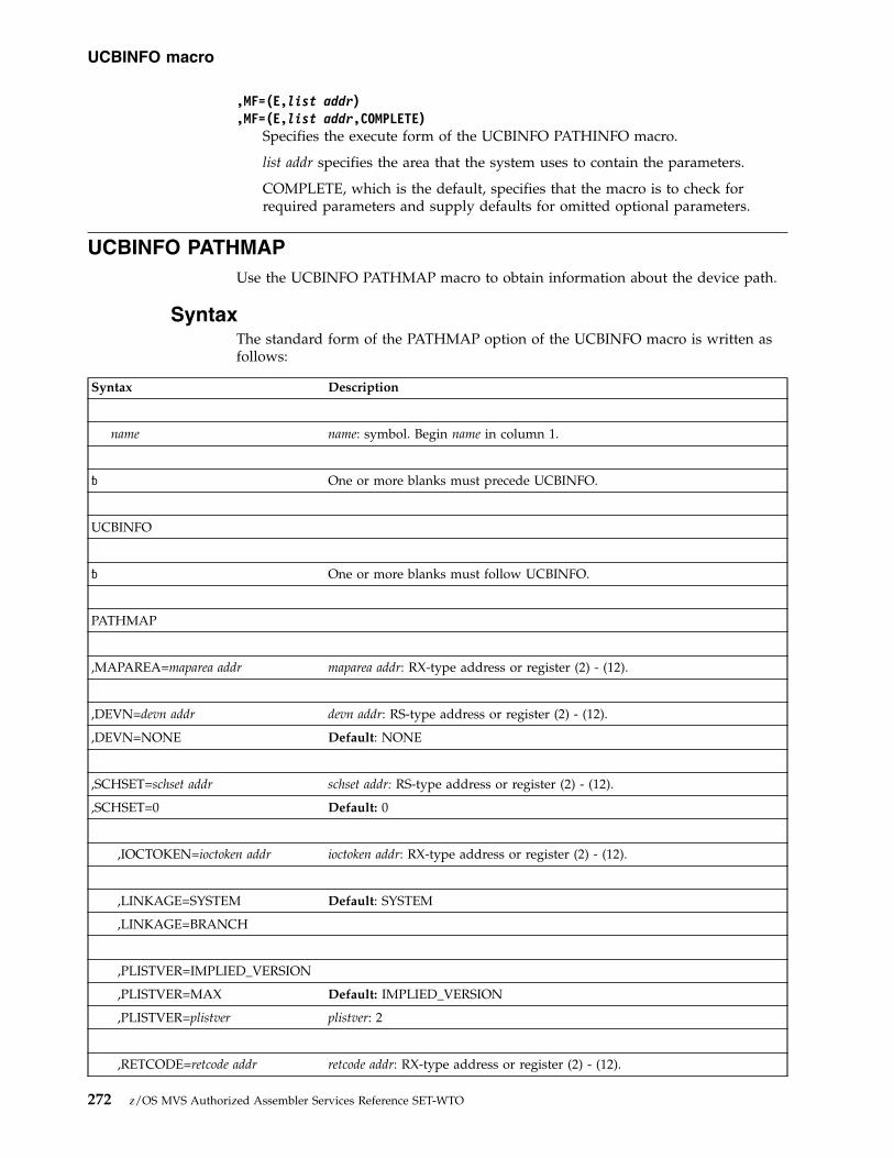
,MF=(E,list addr),MF=(E,list addr,COMPLETE)
Specifies the execute form of the UCBINFO PATHINFO macro.
list addr specifies the area that the system uses to contain the parameters.
COMPLETE, which is the default, specifies that the macro is to check forrequired parameters and supply defaults for omitted optional parameters.
UCBINFO PATHMAPUse the UCBINFO PATHMAP macro to obtain information about the device path.
SyntaxThe standard form of the PATHMAP option of the UCBINFO macro is written asfollows:
Syntax Description
name name: symbol. Begin name in column 1.
� One or more blanks must precede UCBINFO.
UCBINFO
� One or more blanks must follow UCBINFO.
PATHMAP
,MAPAREA=maparea addr maparea addr: RX-type address or register (2) - (12).
,DEVN=devn addr devn addr: RS-type address or register (2) - (12).
,DEVN=NONE Default: NONE
,SCHSET=schset addr schset addr: RS-type address or register (2) - (12).
,SCHSET=0 Default: 0
,IOCTOKEN=ioctoken addr ioctoken addr: RX-type address or register (2) - (12).
,LINKAGE=SYSTEM Default: SYSTEM
,LINKAGE=BRANCH
,PLISTVER=IMPLIED_VERSION
,PLISTVER=MAX Default: IMPLIED_VERSION
,PLISTVER=plistver plistver: 2
,RETCODE=retcode addr retcode addr: RX-type address or register (2) - (12).
UCBINFO macro
272 z/OS MVS Authorized Assembler Services Reference SET-WTO

Syntax Description
,RSNCODE=rsncode addr rsncode addr: RX-type address or register (2) - (12).
ParametersThe parameters are explained as follows:
PATHMAPSpecifies that the system is to return information about the device path for thespecified device.
,MAPAREA=maparea addrSpecifies a required 40-byte field into which the system is to return informationabout the device path for the specified device. This field is mapped by themapping macro IOSDMAP.
,DEVN=devn addr,DEVN=NONE
Specifies the address of a halfword that contains, in binary form, the devicenumber of the device.
If the caller does not specify an address on the DEVN parameter, or specifiesDEVN=NONE, the caller must place the address of the UCB common segmentinto the fullword field within the MAPAREA DSECT that is assigned the nameMAPUCB by mapping macro IOSDMAP. See z/OS MVS Programming:Authorized Assembler Services Guide for information about using UCBSCAN toobtain the address of the UCB.
If the caller codes the DEVN parameter, the MAPUCB field containshexadecimal zeros when control returns to the caller.
,SCHSET=schset addr,SCHSET=0
Specifies the name (RS-type), or address in register (2)-(12), of an optional byteinput that specifies a subchannel set for which the information about thedevice path is to be returned. DEFAULT: 0.
,IOCTOKEN=ioctoken addrSpecifies the address of a 48-character storage area that contains the MVS I/Oconfiguration token. The caller can obtain this token by issuing the IOCINFOmacro, which is described in z/OS MVS Programming: Assembler ServicesReference ABE-HSP. If the I/O configuration token that is current whenUCBINFO is invoked does not match the token whose address is suppliedhere, the system issues a return code to the caller.
If you set the input IOCTOKEN (specified by ioctoken addr) to binary zeros,UCBINFO sets IOCTOKEN to the current I/O configuration token.
,LINKAGE=SYSTEM,LINKAGE=BRANCH
Specifies the type of call that the system is to generate:v SYSTEM: Specifies a Program Call (PC)v BRANCH: Specifies a Branch entry
LINKAGE=BRANCH is intended for performance-sensitive programs.
,PLISTVER=IMPLIED_VERSION
UCBINFO macro
Chapter 24. UCBINFO — Return information from a UCB 273
|
|

,PLISTVER=MAX,PLISTVER=plistver
Specifies the version of the macro. PLISTVER determines which parameter listthe system generates. PLISTVER is an optional input parameter on all forms ofthe macro, including the list form. When using PLISTVER, specify it on allmacro forms used for a request and with the same value on all of the macroforms. The values are:v IMPLIED_VERSION, which is the lowest version that allows all parameters
specified on the request to be processed. If you omit the PLISTVERparameter, IMPLIED_VERSION is the default.
v MAX, if you want the parameter list to be the largest size currently possible.This size might grow from release to release and affect the amount ofstorage that your program needs.If you can tolerate the size change, IBM recommends that you alwaysspecify PLISTVER=MAX on the list form of the macro. Specifying MAXensures that the list-form parameter list is always long enough to hold allthe parameters you might specify on the execute form; in this way, MAXensures that the parameter list does not overwrite nearby storage.
v 2, if you use the currently available parameters.
To code, specify in this input parameter one of the following:v IMPLIED_VERSIONv MAXv A decimal value of 2
,RETCODE=retcode addrSpecifies the address of a fullword field into which the system copies thereturn code from GPR 15.
,RSNCODE=rsncode addrSpecifies the address of a fullword field into which the system copies thereason code from GPR 0.
Return and reason codesWhen the UCBINFO PATHMAP macro returns control to your program, GPR 15(or retcode addr, if you coded RETCODE) contains a return code, and GPR 0 (orrsncode addr, if you coded RSNCODE) contains a reason code.
Hexadecimal ReturnCode
Hexadecimal ReasonCode Meaning and Action
00 None Meaning: The PATHMAP function completedsuccessfully.
Action: None.
04 None Meaning: Program error. No UCB exists for thedevice number specified in the DEVN parameter.
Action: Correct the device number and reissuethe macro.
08 01 Meaning: Program error. A caller in AR modespecified an ALET that was not valid.
Action: Correct the ALET and reissue the macro.
UCBINFO macro
274 z/OS MVS Authorized Assembler Services Reference SET-WTO

Hexadecimal ReturnCode
Hexadecimal ReasonCode Meaning and Action
08 02 Meaning: Program error. An error occurred whenthe system tried to access the caller's parameterlist. This might be due to using a keyword thatrequires authorization but the caller was notauthorized, that is the Supervisor state or PSWkey 0 - 7.
Action: Ensure that you have met theenvironmental requirements for the macro, andreissue the macro.
08 03 Meaning: Program error. The UCB addressprovided by the caller does not represent a validUCB.
Action: Correct the UCB address and reissue themacro.
08 05 Meaning: Program error. An error occurred whenthe system referenced the caller-supplied areaspecified in the IOCTOKEN parameter. Thisreason code is valid only for callers using theIOCTOKEN parameter.
Action: Correct the IOCTOKEN parameter.
08 06 Meaning: Program error. An error occurred whenthe system attempted to reference the areaspecified by the MAPAREA parameter.
Action: Correct the address specified forMAPAREA and reissue the macro.
08 0B Meaning: The value specified on the SCHSETkeyword is not valid.
Action: Enter a valid value.
0C None Meaning: Environmental error. The I/Oconfiguration token supplied through theIOCTOKEN parameter is not current. This returncode is valid only for callers using theIOCTOKEN parameter.
Action: Obtain the current I/O configurationtoken by issuing an IOCINFO macro or bysetting the input IOCTOKEN parameter in theUCBINFO macro to zero.
10 04 Meaning: System error. The subchannel is inpermanent error and cannot be accessed.
Action: Supply the return and reason code to theappropriate IBM support personnel.
10 08 Meaning: Environmental error. The UCB is notconnected to a subchannel.
Action: Correct the UCB address supplied, andreissue the macro.
20 None Meaning: System error. An unexpected erroroccurred.
Action: Supply the return code to the appropriateIBM support personnel.
ExampleTo invoke UCBINFO to return device path information, code:
UCBINFO macro
Chapter 24. UCBINFO — Return information from a UCB 275
||||

UCBINFO PATHMAP,MAPAREA=INFOAREA,DEVN=DEVNUM, XRETCODE=INFORTCD...
DS 0DINFOAREA DS CL256INFORTCD DS FDEVNUM DS H
UCBINFO PATHMAP - List formUse the list form of the PATHMAP option of the UCBINFO macro together withthe execute form for applications that require reentrant code. The list form of themacro defines an area of storage that the execute form uses to contain theparameters.
This macro is an alternative list form macro, and requires a different technique forusing the list form as compared to the conventional list form macros. See“Alternative list form macros” on page 13 for further information.
The list form of the PATHMAP option of the UCBINFO macro is written asfollows:
Syntax Description
name name: symbol. Begin name in column 1.
� One or more blanks must precede UCBINFO.
UCBINFO
� One or more blanks must follow UCBINFO.
,PLISTVER=IMPLIED_VERSION
,PLISTVER=MAX Default: IMPLIED_VERSION
,PLISTVER=plistver plistver: 2
MF=(L,list addr) list addr: RX-type address
MF=(L,list addr, attr) attr: 1- to 60-character input string
MF=(L,list addr,0D) Default: 0D
ParametersThe parameters are explained under the standard form of UCBINFO PATHMAPwith the following exceptions:
MF=(L,list addr)MF=(L,list addr,attr)
UCBINFO macro
276 z/OS MVS Authorized Assembler Services Reference SET-WTO

MF=(L,list addr,0D)Specifies the list form of the UCBINFO PATHMAP macro.
list addr is the name of a storage area to contain the parameters.
attr is an optional 1- to 60-character input string, which can contain any valuethat is valid on an assembler DS pseudo-op. You can use this parameter toforce boundary alignment of the parameter list. If you do not code attr, thesystem provides a value of 0D, which forces the parameter list to adoubleword boundary.
UCBINFO PATHMAP - Execute formUse the execute form of the PATHMAP option of the UCBINFO macro togetherwith the list form of the macro for applications that require reentrant code. Theexecute form of the macro stores the parameters into the storage area defined bythe list form.
The execute form of the PATHMAP option of the UCBINFO macro is written asfollows:
Syntax Description
name name: symbol. Begin name in column 1.
� One or more blanks must precede UCBINFO.
UCBINFO
� One or more blanks must follow UCBINFO.
PATHMAP
,MAPAREA=maparea addr maparea addr: RX-type address or register (2) - (12).
,DEVN=devn addr devn addr: RX-type address or register (2) - (12).
,DEVN=NONE Default: NONE
,SCHSET=schset addr schset addr: RS-type address or register (2) - (12).
,SCHSET=0 Default: 0
,IOCTOKEN=ioctoken addr ioctoken addr: RX-type address or register (2) - (12).
,LINKAGE=SYSTEM Default: SYSTEM
,LINKAGE=BRANCH
,PLISTVER=IMPLIED_VERSION
,PLISTVER=MAX Default: IMPLIED_VERSION
UCBINFO macro
Chapter 24. UCBINFO — Return information from a UCB 277

Syntax Description
,PLISTVER=plistver plistver: 2
,RETCODE=retcode addr retcode addr: RX-type address or register (2) - (12).
,RSNCODE=rsncode addr rsncode addr: RX-type address or register (2) - (12).
,MF=(E,list addr) list addr: RX-type address or address in register (2) - (12).
,MF=(E,list addr,COMPLETE) Default: COMPLETE
ParametersThe parameters are explained under the standard form of the UCBINFOPATHMAP macro with the following exceptions:
,MF=(E,list addr),MF=(E,list addr,COMPLETE)
Specifies the execute form of the UCBINFO PATHMAP macro.
list addr specifies the area that the system uses to contain the parameters.
COMPLETE, which is the default, specifies that the macro is to check forrequired parameters and supply defaults for omitted optional parameters.
UCBINFO PAVINFOUse the UCBINFO PAVINFO macro to obtain selected information applicable toeach exposure (base and alias) of a Parallel Access Volume (PAV).
If using a UCB copy, the user must pass the device number in DEVN. The callercan obtain the address of the UCB common segment by a UCBPTR parameter on aUCBLOOK macro. The use of UCBPTR is restricted to callers in Supervisor state orPSW key 0 - 7.
SyntaxThe standard form of the PAVINFO option of the UCBINFO macro is written asfollows:
Syntax Description
name name: symbol. Begin name in column 1.
� One or more blanks must precede UCBINFO.
UCBINFO
� One or more blanks must follow UCBINFO.
PAVINFO
UCBINFO macro
278 z/OS MVS Authorized Assembler Services Reference SET-WTO

Syntax Description
PAVINFOSUM=NO Default: NO
PAVINFOSUM=YES
,PAVAREA=pavarea addr pavarea addr: RX-type address or register (2) - (12).
,PAVLEN=pavarea addr pavarea addr: RX-type address or register (2) - (12).
,SCHINFO=NO Default: NO
,SCHINFO=YES
,EXTFORMAT=NO Default: NO
,EXTFORMAT=YES
,OUTVERSION=outver Default: 3
,DEVN=devn addr devn addr: RS-type address or register (2) - (12).
Note: Specify either DEVN or UCBPTR, but not both.
,SCHSET=schset addr schset addr: RS-type address or register (2) - (12).
,SCHSET=0 Default: 0
,UCBPTR=ucbptr ucbptr: RX-type address.
Note: Specify either DEVN or UCBPTR, but not both.
,IOCTOKEN=ioctoken addr ioctoken addr: RX-type address or register (2) - (12).
,LINKAGE=SYSTEM Default: SYSTEM
,LINKAGE=BRANCH
,PLISTVER=IMPLIED_VERSION
,PLISTVER=MAX Default: IMPLIED_VERSION
,PLISTVER=plistver plistver: 2
,RETCODE=retcode addr retcode addr: RX-type address or register (2) - (12).
,RSNCODE=rsncode addr rsncode addr: RX-type address or register (2) - (12).
ParametersThe parameters are explained as follows:
UCBINFO macro
Chapter 24. UCBINFO — Return information from a UCB 279

PAVINFOObtain selected information that applies to each exposure of a Parallel AccessVolume (PAV) device. The data returned by this function is mapped by themapping macro IOSDPAVA and consists of a header and one or more entries.Depending on the input device, the following is returned:v When the input device is a PAV-base, the first entry represents the base and
each subsequent entry represents each of the bound PAV-alias devicesassociated with the base. Note that if the base has no bound PAV-aliases,then only the first entry is filled in.
v When the input is a non-PAV DASD device, only the first entry is filled in.v When the input device is a PAV-alias or a non-DASD, a non-zero return code
is returned.
PAVINFOSUM=NOPAVINFOSUM=YES
Specifies whether to retrieve only a sum of channel measurement data andmodel dependent subchannel data for the base device and all of its aliases.
Note: The model dependent subchannel data is only retrieved ifSCHINFO=YES.
NO Do not just retrieve a total of channel measurement data and modeldependent subchannel data for the base device and all of its aliases.This option causes a PAVA entry to be created for the base device andeach of its aliases.
YES Retrieve only a sum of channel measurement data and modeldependent subchannel data for the base device and all of its aliases.This option causes the first PAVA entry to contain information on thebase device, however, the measurement-related fields (such asPAVACMB, PAVASMDB, and PAVAECMB) will contain totals for thebase and all of its aliases.
,PAVAREA=pavarea addrSpecifies the address of a required output field into which the system willreturn information about the alias UCBs for the specified base device numberor base UCB address. This field is mapped by the mapping macro IOSDPAVA.
,PAVLEN=pavarea addrSpecifies the address or a register containing the length of the areaspecified by the PAVAREA parameter.
,SCHINFO=NO,SCHINFO=YES
This parameter specifies whether or not to retrieve model-dependentsubchannel data (control unit busy time, switch busy time, and devicebusy time) for the device. If you issue this request from a system runningon a z990 or higher processor, the system ignores the SCHINFO parameter,but still returns the device busy time.
NO Do not retrieve model-dependent subchannel data for the device.Note that even if you specify NO on a z990 or higher processor,the service will still return the device busy time.
YES Retrieve model-dependent subchannel data for the device, whichincludes control unit busy time, switch busy time, and device busytime. If you specify YES on a z990 or higher processor, the servicewill still return the device busy time.
,EXTFORMAT=NO
UCBINFO macro
280 z/OS MVS Authorized Assembler Services Reference SET-WTO

,EXTFORMAT=YESThis parameter specifies whether an extended format PAV area should becreated. An extended format PAV area contains a length field in each entrythat defines the actual length of the entry. This allows the PAV entry to beextended compatibly to add new information. A non-extended format PAVarea contains entries which are fixed in size (60 bytes) and cannot beextended to contain new data. See the mapping macro IOSDPAVA for moreinformation.
Note: The value specified for the EXTFORMAT keyword on the UCBINFOPAVINFO macro must match the value specified on the IOSDPAVA macro.Otherwise, your program may not work correctly.
NO Create the non-extended format PAV area.
YES Create the extended format PAV area.
,OUTVERSION=outverSpecifies the output version to be used when creating an extendedformat PAV area. The output version controls the size of the PAVentries that are returned. This parameter is used only ifEXTFORMAT(YES) is specified; it is ignored for EXTFORMAT(NO)requests. If an output version that is less than 3 is specified, version 3is used. If an output version that is higher than the currentlysupported version is specified, the highest supported version is used.
Note: Currently, version 3 is the only supported value.
,DEVN=devn addrSpecifies the address of a halfword that contains the base device number inbinary form. The DEVN and UCBPTR parameters are mutually exclusive.
,SCHSET=schset addr,SCHSET=0
Specifies the name (RS-type), or address in register (2)-(12), of an optional byteinput that specifies a subchannel set for which the information that applies toeach exposure of a Parallel Access Volume (PAV) device is to be obtained.DEFAULT: 0.
,UCBPTR=ucbptr addrSpecifies the address of a fullword that contains the address of the UCBcommon segment. The DEVN and UCBPTR parameters are mutually exclusive.The use of UCBPTR is restricted to callers in Supervisor state or PSW key 0 - 7.
,IOCTOKEN=ioctoken addrSpecifies the address of a 48-character storage area that contains the MVS I/Oconfiguration token. The caller can obtain this token by issuing the IOCINFOmacro, which is described in z/OS MVS Programming: Assembler ServicesReference ABE-HSP. If the I/O configuration token that is current whenUCBINFO is invoked does not match the token whose address is suppliedhere, the system issues a return code to the caller.
If you set the input IOCTOKEN (specified by ioctoken addr) to binary zeros,UCBINFO sets IOCTOKEN to the current I/O configuration token.
,LINKAGE=SYSTEM,LINKAGE=BRANCH
Specifies the type of call that the system is to generate:v SYSTEM: Specifies a program call (PC)v BRANCH: Specifies a branch entry
UCBINFO macro
Chapter 24. UCBINFO — Return information from a UCB 281
|

LINKAGE=BRANCH is intended for performance sensitive programs.
,PLISTVER=IMPLIED_VERSION,PLISTVER=MAX,PLISTVER=plistver
Specifies the version of the macro. PLISTVER determines which parameter listthe system generates. PLISTVER is an optional input parameter on all forms ofthe macro, including the list form. When using PLISTVER, specify it on allmacro forms used for a request and with the same value on all of the macroforms. The values are:v IMPLIED_VERSION, which is the lowest version that allows all parameters
specified on the request to be processed. If you omit the PLISTVERparameter, IMPLIED_VERSION is the default.
v MAX, if you want the parameter list to be the largest size currently possible.This size might grow from release to release and affect the amount ofstorage that your program needs.If you can tolerate the size change, IBM recommends that you alwaysspecify PLISTVER=MAX on the list form of the macro. Specifying MAXensures that the list-form parameter list is always long enough to hold allthe parameters you might specify on the execute form; in this way, MAXensures that the parameter list does not overwrite nearby storage.
v 2, if you use the currently available parameters.
To code, specify in this input parameter one of the following:v IMPLIED_VERSIONv MAXv A decimal value in the range of 1 - 3.
,RETCODE=retcode addrSpecifies the address of a fullword field into which the system copies thereturn code from GPR 15.
,RSNCODE=rsncode addrSpecifies the address of a fullword field into which the system copies thereason code from GPR 0.
Return and reason codesWhen the UCBINFO PAVINFO macro returns control to your program, GPR 15 (orretcode addr, if you coded RETCODE) contains a return code, and GPR 0 (or rsncodeaddr, if you coded RSNCODE) contains a reason code.
Hexadecimal ReturnCode
Hexadecimal ReasonCode Meaning and Action
00 None Meaning: The PAVINFO function completedsuccessfully.
Action: None.
04 None Meaning: Program error. No UCB exists for thedevice number specified in the DEVN parameter.
Action: Correct the device number and reissuethe macro.
08 01 Meaning: Program error. A caller in AR modespecified an ALET that was not valid.
Action: Correct the ALET and reissue the macro.
UCBINFO macro
282 z/OS MVS Authorized Assembler Services Reference SET-WTO
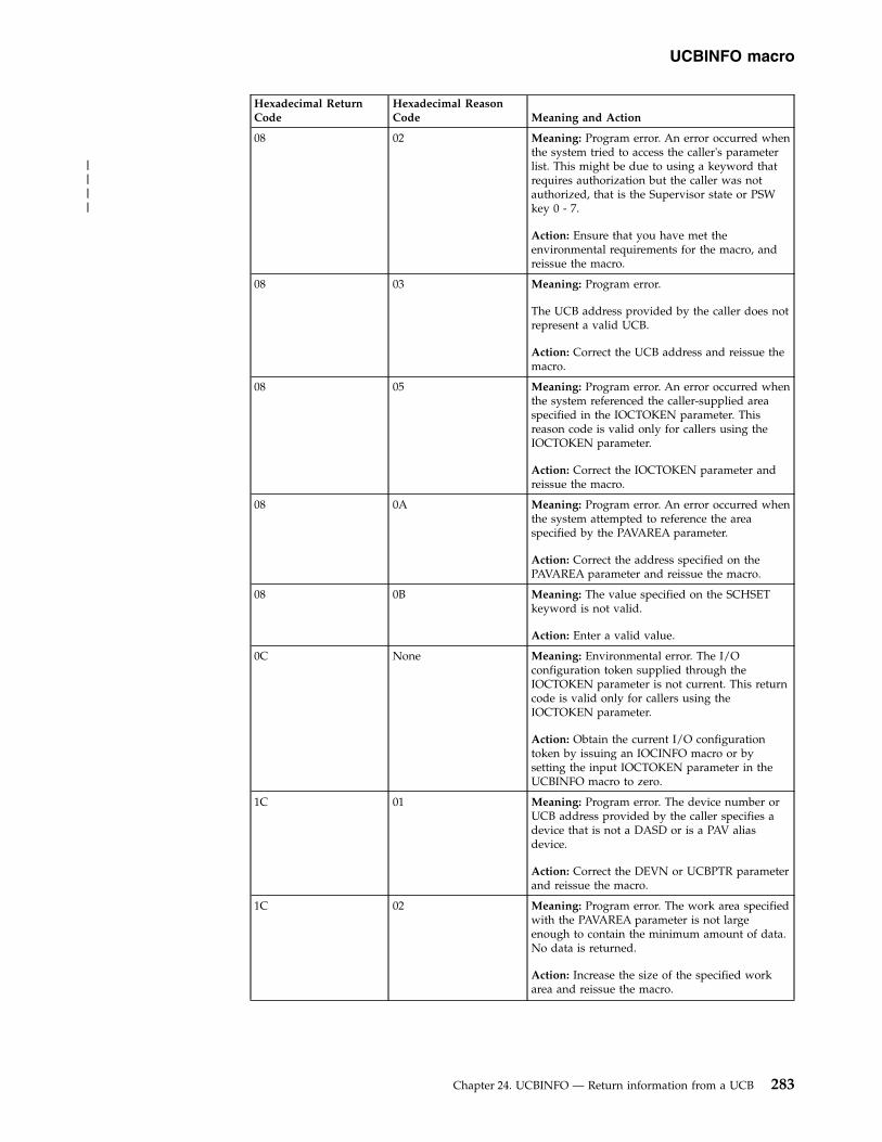
Hexadecimal ReturnCode
Hexadecimal ReasonCode Meaning and Action
08 02 Meaning: Program error. An error occurred whenthe system tried to access the caller's parameterlist. This might be due to using a keyword thatrequires authorization but the caller was notauthorized, that is the Supervisor state or PSWkey 0 - 7.
Action: Ensure that you have met theenvironmental requirements for the macro, andreissue the macro.
08 03 Meaning: Program error.
The UCB address provided by the caller does notrepresent a valid UCB.
Action: Correct the UCB address and reissue themacro.
08 05 Meaning: Program error. An error occurred whenthe system referenced the caller-supplied areaspecified in the IOCTOKEN parameter. Thisreason code is valid only for callers using theIOCTOKEN parameter.
Action: Correct the IOCTOKEN parameter andreissue the macro.
08 0A Meaning: Program error. An error occurred whenthe system attempted to reference the areaspecified by the PAVAREA parameter.
Action: Correct the address specified on thePAVAREA parameter and reissue the macro.
08 0B Meaning: The value specified on the SCHSETkeyword is not valid.
Action: Enter a valid value.
0C None Meaning: Environmental error. The I/Oconfiguration token supplied through theIOCTOKEN parameter is not current. This returncode is valid only for callers using theIOCTOKEN parameter.
Action: Obtain the current I/O configurationtoken by issuing an IOCINFO macro or bysetting the input IOCTOKEN parameter in theUCBINFO macro to zero.
1C 01 Meaning: Program error. The device number orUCB address provided by the caller specifies adevice that is not a DASD or is a PAV aliasdevice.
Action: Correct the DEVN or UCBPTR parameterand reissue the macro.
1C 02 Meaning: Program error. The work area specifiedwith the PAVAREA parameter is not largeenough to contain the minimum amount of data.No data is returned.
Action: Increase the size of the specified workarea and reissue the macro.
UCBINFO macro
Chapter 24. UCBINFO — Return information from a UCB 283
||||

Hexadecimal ReturnCode
Hexadecimal ReasonCode Meaning and Action
1C 03 Meaning: Program error. The work area specifiedwith the PAVAREA parameter is not largeenough to contain an entry for each alias device.
Action: Increase the size of the specified workarea and reissue the macro.
20 None Meaning: System error. An unexpected erroroccurred.
Action: Supply the return code to the appropriateIBM support personnel.
28 None Meaning: Program error. The device number orUCB address provided by the caller represents analias UCB of a parallel access volume. The callermust specify the base device number or baseUCB.
Action: Correct the DEVN or UCBPTR parameterand reissue the macro.
ExampleTo invoke UCBINFO to return information about alias UCBs for a base devicenumber, code:
UCBINFO PAVINFO,DEVN=DEVNUM,PAVAREA=INFOAREA,PAVLEN=AREALEN, XRETCODE=INFORTCD
.
.
.DS 0D
DEVNUM DS HINFOAREA DS CL256AREALEN DS FINFORTCD DS F
To invoke UCBINFO to return information about alias UCBs for a base UCB, code:UCBINFO PAVINFO,UCBPTR=UCBP,PAVAREA=INFOAREA,PAVLEN=AREALEN, X
RETCODE=INFORTCD...DS 0D
UCBP DS AINFOAREA DS CL256AREALEN DS FINFORTCD DS F
UCBINFO PAVINFO - List formUse the list form of the PAVINFO option of the UCBINFO macro together with theexecute form for applications that require reentrant code. The list form of themacro defines an area of storage that the execute form uses to contain theparameters.
The list form of the PAVINFO option of the UCBINFO macro is written as follows:
Syntax Description
UCBINFO macro
284 z/OS MVS Authorized Assembler Services Reference SET-WTO

Syntax Description
name name: symbol. Begin name in column 1.
� One or more blanks must precede UCBINFO.
UCBINFO
� One or more blanks must follow UCBINFO.
,PLISTVER=IMPLIED_VERSION
,PLISTVER=MAX Default: IMPLIED_VERSION
,PLISTVER=plistver plistver: 2
MF=(L,list addr) list addr: RX-type address
MF=(L,list addr, attr) attr: 1- to 60-character input string
MF=(L,list addr,0D) Default: 0D
ParametersThe parameters are explained under the standard form of UCBINFO PAVINFOwith the following exceptions:
MF=(L,list addr)MF=(L,list addr,attr)MF=(L,list addr,0D)
Specifies the list form of the UCBINFO PAVINFO macro.
list addr is the name of a storage area to contain the parameters.
attr is an optional 1- to 60-character input string, which can contain any valuethat is valid on an assembler DS pseudo-op. You can use this parameter toforce boundary alignment of the parameter list. If you do not code attr, thesystem provides a value of X'0D', which forces the parameter list to adoubleword boundary.
UCBINFO PAVINFO - Execute formUse the execute form of the PAVINFO option of the UCBINFO macro together withthe list form of the macro for applications that require reentrant code. The executeform of the macro stores the parameters into the storage area defined by the listform.
The execute form of the PAVINFO option of the UCBINFO macro is written asfollows:
Syntax Description
name name: symbol. Begin name in column 1.
� One or more blanks must precede UCBINFO.
UCBINFO macro
Chapter 24. UCBINFO — Return information from a UCB 285

Syntax Description
UCBINFO
� One or more blanks must follow UCBINFO.
PAVINFO
PAVINFOSUM=NO Default: NO
PAVINFOSUM=YES
,PAVAREA=pavarea addr pavarea addr: RX-type address or register (2) - (12).
,PAVLEN=pavlen addr pavlen addr: RX-type address or register (2) - (12).
,SCHINFO=NO Default: NO
,SCHINFO=YES
,EXTFORMAT=NO Default: NO
,EXTFORMAT=YES
,OUTVERSION=outver Default: 3
,DEVN=devn addr devn addr: RX-type address or register (2) - (12).
Note: Specify either DEVN or UCBPTR, but not both.
,SCHSET=schset addr schset addr: RS-type address or register (2) - (12).
,SCHSET=0 Default: 0
,UCBPTR=ucbptr addr ucbptr addr:: RX-type address.
Note: Specify either DEVN or UCBPTR, but not both.
,IOCTOKEN=ioctoken addr ioctoken addr: RX-type address or register (2) - (12).
,LINKAGE=SYSTEM Default: SYSTEM
,LINKAGE=BRANCH
,PLISTVER=IMPLIED_VERSION
,PLISTVER=MAX Default: IMPLIED_VERSION
,PLISTVER=plistver plistver: 2
,RETCODE=retcode addr retcode addr: RX-type address or register (2) - (12).
UCBINFO macro
286 z/OS MVS Authorized Assembler Services Reference SET-WTO

Syntax Description
,RSNCODE=rsncode addr rsncode addr: RX-type address or register (2) - (12).
,MF=(E,list addr) list addr: RX-type address or address in register (2) - (12).
,MF=(E,list addr,COMPLETE) Default: COMPLETE
ParametersThe parameters are explained under the standard form of UCBINFO PAVINFOwith the following exceptions:
,MF=(E,list addr),MF=(E,list addr,COMPLETE)
Specifies the execute form of the UCBINFO PAVINFO macro.
list addr specifies the area that the system uses to contain the parameters.
COMPLETE, which is the default, specifies that the macro is to check forrequired parameters and supply defaults for omitted optional parameters.
UCBINFO PRFXDATAUse the UCBINFO PRFXDATA macro to obtain a copy of the UCB prefix extensionsegment.
If using a UCB copy, the user must pass the device number in DEVN. The callercan obtain the address of the UCB common segment by a UCBPTR parameter on aUCBLOOK macro. The use of UCBPTR is restricted to callers in Supervisor state orPSW key 0 - 7.
SyntaxThe standard form of the PRFXDATA option of the UCBINFO macro is written asfollows:
Syntax Description
name name: symbol. Begin name in column 1.
� One or more blanks must precede UCBINFO.
UCBINFO
� One or more blanks must follow UCBINFO.
PRFXDATA
,DEVN=devn addr devn addr: RS-type address or register (2) - (12).
Note: Specify either DEVN or UCBPTR, but not both.
UCBINFO macro
Chapter 24. UCBINFO — Return information from a UCB 287

Syntax Description
,SCHSET=schset addr schset addr: RS-type address or register (2) - (12).
,SCHSET=0 Default: 0
,UCBPTR=ucbptr addr ucbptr addr: RS-type address or register (2) - (12).
Note: Specify either DEVN or UCBPTR, but not both.
,UCBPAREA=ucbparea addr ucbparea addr: RX-type address or register (2) - (12).
,IOCTOKEN=ioctoken addr ioctoken addr: RX-type address or register (2) - (12).
,LINKAGE=SYSTEM Default: SYSTEM
,LINKAGE=BRANCH
,PLISTVER=IMPLIED_VERSION
,PLISTVER=MAX Default: IMPLIED_VERSION
,PLISTVER=plistver plistver: 2
,RETCODE=retcode addr retcode addr: RX-type address or register (2) - (12).
,RSNCODE=rsncode addr rsncode addr: RX-type address or register (2) - (12).
ParametersThe parameters are explained as follows:
PRFXDATASpecifies that the system is to obtain information from the UCB prefixextension segment.
,DEVN=devn addrSpecifies the address of a halfword that contains, in binary form, the devicenumber of the device. The DEVN and UCBPTR parameters are mutuallyexclusive.
,SCHSET=schset addr,SCHSET=0
Specifies the name (RS-type), or address in register (2)-(12), of an optional byteinput that specifies a subchannel set for which the information from the UCBprefix extension segment is to be obtained. DEFAULT: 0.
,UCBPTR=ucbptr addrSpecifies the address of a fullword that contains the address of the UCBcommon segment. The use of UCBPTR is restricted to callers in Supervisorstate or PSW key 0 - 7. The DEVN and UCBPTR parameters are mutuallyexclusive.
UCBINFO macro
288 z/OS MVS Authorized Assembler Services Reference SET-WTO
||
|||

,UCBPAREA=ucbparea addrSpecifies the address of a 48-character storage area into which the systemcopies the UCB prefix extension segment. The IOSDUPI mapping macro mapsthe area.
,IOCTOKEN=ioctoken addrSpecifies the address of a 48-character storage area that contains the MVS I/Oconfiguration token. The caller can obtain this token by issuing the IOCINFOmacro, which is described in z/OS MVS Programming: Assembler ServicesReference ABE-HSP. If the I/O configuration token that is current whenUCBINFO is invoked does not match the token whose address is suppliedhere, the system issues a return code to the caller.
If you set the input IOCTOKEN (specified by ioctoken addr) to binary zeros,UCBINFO sets IOCTOKEN to the current I/O configuration token.
,LINKAGE=SYSTEM,LINKAGE=BRANCH
Specifies the type of call that the system is to generate:v SYSTEM: Specifies a Program Call (PC)v BRANCH: Specifies a Branch entry
LINKAGE=BRANCH is intended for performance-sensitive programs.
,PLISTVER=IMPLIED_VERSION,PLISTVER=MAX,PLISTVER=plistver
Specifies the version of the macro. PLISTVER determines which parameter listthe system generates. PLISTVER is an optional input parameter on all forms ofthe macro, including the list form. When using PLISTVER, specify it on allmacro forms used for a request and with the same value on all of the macroforms. The values are:v IMPLIED_VERSION, which is the lowest version that allows all parameters
specified on the request to be processed. If you omit the PLISTVERparameter, IMPLIED_VERSION is the default.
v MAX, if you want the parameter list to be the largest size currently possible.This size might grow from release to release and affect the amount ofstorage that your program needs.If you can tolerate the size change, IBM recommends that you alwaysspecify PLISTVER=MAX on the list form of the macro. Specifying MAXensures that the list-form parameter list is always long enough to hold allthe parameters you might specify on the execute form; in this way, MAXensures that the parameter list does not overwrite nearby storage.
v 2, if you use the currently available parameters.
To code, specify in this input parameter one of the following:v IMPLIED_VERSIONv MAXv A decimal value of 2
,RETCODE=retcode addrSpecifies the address of a fullword field into which the system copies thereturn code from GPR 15.
,RSNCODE=rsncode addrSpecifies the address of a fullword field into which the system copies thereason code from GPR 0.
UCBINFO macro
Chapter 24. UCBINFO — Return information from a UCB 289

Return and reason codesWhen the UCBINFO PRFXDATA macro returns control to your program, GPR 15(or retcode addr, if you coded RETCODE) contains a return code, and GPR 0 (orrsncode addr, if you coded RSNCODE) contains a reason code.
Hexadecimal ReturnCode
Hexadecimal ReasonCode Meaning and Action
00 None Meaning: The PRFXDATA function completedsuccessfully.
Action: None.
04 None Meaning: Program error. No UCB exists for thedevice number specified in the DEVN parameter.
Action: Correct the device number and reissuethe macro.
08 01 Meaning: Program error. A caller in AR modespecified an ALET that was not valid.
Action: Correct the ALET and reissue the macro.
08 02 Meaning: Program error. An error occurred whenthe system tried to access the caller's parameterlist. This might be due to using a keyword thatrequires authorization but the caller was notauthorized, that is the Supervisor state or PSWkey 0 - 7.
Action: Ensure that you have met theenvironmental requirements for the macro, andreissue the macro.
08 03 Meaning: Program error.
The UCB address provided by the caller does notrepresent a valid UCB.
Action: Correct the UCB address and reissue themacro.
08 05 Meaning: Program error. An error occurred whenthe system referenced the caller-supplied areaspecified in the IOCTOKEN parameter. Thisreason code is valid only for callers using theIOCTOKEN parameter.
Action: Correct the IOCTOKEN parameter.
08 0B Meaning: The value specified on the SCHSETkeyword is not valid.
Action: Enter a valid value.
0C None Meaning: Environmental error. The I/Oconfiguration token supplied through theIOCTOKEN parameter is not current. This returncode is valid only for callers using theIOCTOKEN parameter.
Action: Obtain the current I/O configurationtoken by issuing an IOCINFO macro or bysetting the input IOCTOKEN parameter in theUCBINFO macro to zero.
20 None Meaning: System error. An unexpected erroroccurred.
Action: Supply the return code to the appropriateIBM support personnel.
UCBINFO macro
290 z/OS MVS Authorized Assembler Services Reference SET-WTO
||||

ExampleTo invoke UCBINFO to obtain a copy of the UCB prefix extension segment, code:
UCBINFO PRFXDATA,DEVN=DEVNUM,UCBPAREA=UAREA, XRETCODE=INFORTCD...
DS 0DDEVNUM DS HUAREA DS CL48INFORTCD DS F
UCBINFO PRFXDATA - List formUse the list form of the PRFXDATA option of the UCBINFO macro together withthe execute form for applications that require reentrant code. The list form of themacro defines an area of storage that the execute form uses to contain theparameters.
This macro is an alternative list form macro, and requires a different technique forusing the list form as compared to the conventional list form macros. See“Alternative list form macros” on page 13 for further information.
The list form of the PRFXDATA option of the UCBINFO macro is written asfollows:
Syntax Description
name name: symbol. Begin name in column 1.
� One or more blanks must precede UCBINFO.
UCBINFO
� One or more blanks must follow UCBINFO.
,PLISTVER=IMPLIED_VERSION
,PLISTVER=MAX Default: IMPLIED_VERSION
,PLISTVER=plistver plistver: 2
MF=(L,list addr) list addr: RX-type address
MF=(L,list addr, attr) attr: 1- to 60-character input string
MF=(L,list addr,0D) Default: 0D
ParametersThe parameters are explained under the standard form of UCBINFO PRFXDATAwith the following exceptions:
UCBINFO macro
Chapter 24. UCBINFO — Return information from a UCB 291

MF=(L,list addr)MF=(L,list addr,attr)MF=(L,list addr,0D)
Specifies the list form of the UCBINFO PRFXDATA macro.
list addr is the name of a storage area to contain the parameters.
attr is an optional 1- to 60-character input string, which can contain any valuethat is valid on an assembler DS pseudo-op. You can use this parameter toforce boundary alignment of the parameter list. If you do not code attr, thesystem provides a value of 0D, which forces the parameter list to adoubleword boundary.
UCBINFO PRFXDATA - Execute formUse the execute form of the PRFXDATA option of the UCBINFO macro togetherwith the list form of the macro for applications that require reentrant code. Theexecute form of the macro stores the parameters into the storage area defined bythe list form.
The execute form of the PRFXDATA option of the UCBINFO macro is written asfollows:
Syntax Description
name name: symbol. Begin name in column 1.
� One or more blanks must precede UCBINFO.
UCBINFO
� One or more blanks must follow UCBINFO.
PRFXDATA
,DEVN=devn addr devn addr: RS-type address or register (2) - (12).
Note: Specify either DEVN or UCBPTR, but not both.
,SCHSET=schset addr schset addr: RS-type address or register (2) - (12).
,SCHSET=0 Default: 0
,UCBPTR=ucbptr addr ucbptr addr: RS-type address or register (2) - (12).
Note: Specify either DEVN or UCBPTR, but not both.
,UCBPAREA=ucbparea addr ucbparea addr: RX-type address or register (2) - (12).
,IOCTOKEN=ioctoken addr ioctoken addr: RX-type address or register (2) - (12).
UCBINFO macro
292 z/OS MVS Authorized Assembler Services Reference SET-WTO
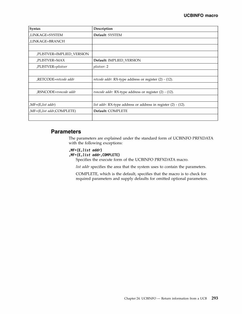
Syntax Description
,LINKAGE=SYSTEM Default: SYSTEM
,LINKAGE=BRANCH
,PLISTVER=IMPLIED_VERSION
,PLISTVER=MAX Default: IMPLIED_VERSION
,PLISTVER=plistver plistver: 2
,RETCODE=retcode addr retcode addr: RX-type address or register (2) - (12).
,RSNCODE=rsncode addr rsncode addr: RX-type address or register (2) - (12).
,MF=(E,list addr) list addr: RX-type address or address in register (2) - (12).
,MF=(E,list addr,COMPLETE) Default: COMPLETE
ParametersThe parameters are explained under the standard form of UCBINFO PRFXDATAwith the following exceptions:
,MF=(E,list addr),MF=(E,list addr,COMPLETE)
Specifies the execute form of the UCBINFO PRFXDATA macro.
list addr specifies the area that the system uses to contain the parameters.
COMPLETE, which is the default, specifies that the macro is to check forrequired parameters and supply defaults for omitted optional parameters.
UCBINFO macro
Chapter 24. UCBINFO — Return information from a UCB 293

UCBINFO macro
294 z/OS MVS Authorized Assembler Services Reference SET-WTO

Chapter 25. UCBLOOK — Obtain addresses of UCB segments
DescriptionThe UCBLOOK macro obtains the address of the following for a given devicenumber or volume serial number:v The UCB common segmentv The UCB common extension segmentv The UCB prefix extension segment
The input device number may be specified as binary or EBCDIC, and may be a3-digit or 4-digit number.
You can use UCBLOOK to locate any UCB segment, including a segment for adynamic UCB. The caller must pin the UCB by means of the PIN parameter unlessone of the following is true:v The caller is running in an environment where dynamic I/O configuration
changes cannot occur.v The caller can otherwise guarantee that the UCB will not be deleted.
After the system returns the address of the UCB segment, and the caller is doneprocessing the UCB, the caller must unpin the UCB. The caller can unpin the UCBby using the UCBPIN macro with the UNPIN parameter.
Note: The caller can optionally restrict the search to UCBs that are static andinstallation-static, have 3 digit device numbers, or are below 16 megabytes.
EnvironmentThe requirements for the caller are:
Environmental factor RequirementMinimum authorization: Supervisor state or PKM keys 0-7
For LINKAGE=BRANCH, all of the following:
v Supervisor state with PSW key 0
v 31-bit addressing mode
v Primary ASC mode
v Parameter list and any data areas it points to must be infixed storage or, if the caller is disabled, in disabledreference (DREF) storage
Dispatchable unit mode: Task or SRBCross memory mode: Any PASN, any HASN, any SASNAMODE: 24- or 31-bitASC mode: Primary or access register (AR)Interrupt status: Enabled or disabled for I/O and external interruptsLocks: No requirementControl parameters: Must be in the primary address space or be in an
address/data space that is addressable through a publicentry on the caller's dispatchable unit access list (DU-AL)
© Copyright IBM Corp. 1988, 2017 295

Programming requirementsIf in AR mode, specify SYSSTATE ASCENV=AR before invoking the macro.
RestrictionsNone.
Input register informationBefore issuing the UCBLOOK macro, the caller does not have to place anyinformation into any register unless using it in register notation for a particularparameter, or using it as a base register.
Output register informationWhen control returns to the caller, the general purpose registers (GPRs) contain:
RegisterContents
0 Reason code if GPR 15 contains a return code of 08; otherwise, used as awork register by the system
1 Used as a work register by the system
2-13 Unchanged
14 Used as a work register by the system
15 Return code
When control returns to the caller, the access registers (ARs) contain:
RegisterContents
0-1 Used as work registers by the system
2-13 Unchanged
14-15 Used as work registers by the system
Performance implicationsNone.
SyntaxThe standard form of the UCBLOOK macro is written as follows:
Syntax Description
name name: Symbol. Begin name in column 1.
� One or more blanks must precede UCBLOOK
UCBLOOK
� One or more blanks must follow UCBLOOK
UCBLOOK macro
296 z/OS MVS Authorized Assembler Services Reference SET-WTO

Syntax Description
DEVN=devn addr devn addr: RS-type address or register (2) - (12).
,SCHSET=xschset xschset RS-type address or register (2) - (12).
,SCHSET=0 Default: 0
LDEVNCHAR=xldevnchar xldevnchar: RS-type address or register (2) - (12).
DEVNCHAR=devnchar addr devnchar addr: RS-type address or register (2) - (12).
VOLSER=volser addr volser addr: RS-type address or register (2) - (12).
,UCBPTR=ucbptr addr ucbptr addr: RS-type address or register (2) - (12).
,UCBCXPTR=ucbcxptr addr ucbcxptr addr: RS-type address or register (2) - (12).
,UCBPXPTR=ucbpxptr addr ucbpxptr addr: RS-type address or register (2) - (12).
,UCBPAREA=ucbparea addr ucbparea addr: RX-type address or register (2) - (12).
,UCBPAREA=NONE Default: NONE
,LOC=BELOW Default: BELOW
,LOC=ANY
SPECIAL=NO Default: NO
SPECIAL=YES
,PIN
,NOPIN Note: TEXT and PTOKEN are required with PIN and are not valid withNOPIN.
,TEXT=text addr text addr: RX-type address
,PTOKEN=ptoken addr ptoken addr: RS-type address or register (2) - (12).
,LASTING Note: Optional with PIN; not valid with NOPIN.
,UNBOUND_ALIAS=NO Default: NO
,UNBOUND_ALIAS=YES
,DEVCLASS=DASD Note: DEVCLASS is valid only with VOLSER=volser addr
,DEVCLASS=DASDTAPE Default: DASDTAPE
,DEVCLASS=TAPE
,DYNAMIC=NO Default: NO
,DYNAMIC=YES
UCBLOOK macro
Chapter 25. UCBLOOK — Obtain addresses of UCB segments 297
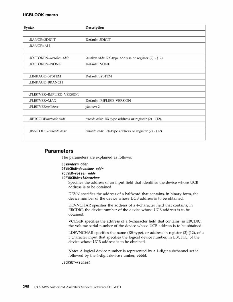
Syntax Description
,RANGE=3DIGIT Default: 3DIGIT
,RANGE=ALL
,IOCTOKEN=ioctoken addr ioctoken addr: RX-type address or register (2) - (12).
,IOCTOKEN=NONE Default: NONE
,LINKAGE=SYSTEM Default SYSTEM
,LINKAGE=BRANCH
,PLISTVER=IMPLIED_VERSION
,PLISTVER=MAX Default: IMPLIED_VERSION
,PLISTVER=plistver plistver: 2
,RETCODE=retcode addr retcode addr: RX-type address or register (2) - (12).
,RSNCODE=rsncode addr rsncode addr: RX-type address or register (2) - (12).
ParametersThe parameters are explained as follows:
DEVN=devn addrDEVNCHAR=devnchar addrVOLSER=volser addrLDEVNCHAR=xldevnchar
Specifies the address of an input field that identifies the device whose UCBaddress is to be obtained.
DEVN specifies the address of a halfword that contains, in binary form, thedevice number of the device whose UCB address is to be obtained.
DEVNCHAR specifies the address of a 4-character field that contains, inEBCDIC, the device number of the device whose UCB address is to beobtained.
VOLSER specifies the address of a 6-character field that contains, in EBCDIC,the volume serial number of the device whose UCB address is to be obtained.
LDEVNCHAR specifies the name (RS-type), or address in register (2)-(12), of a5 character input that specifies the logical device number, in EBCDIC, of thedevice whose UCB address is to be obtained.
Note: A logical device number is represented by a 1-digit subchannel set idfollowed by the 4-digit device number, sdddd.
,SCHSET=xschset
UCBLOOK macro
298 z/OS MVS Authorized Assembler Services Reference SET-WTO
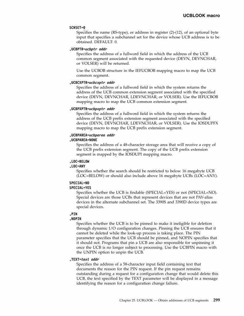
SCHSET=0Specifies the name (RS-type), or address in register (2)-(12), of an optional byteinput that specifies a subchannel set for the device whose UCB address is to beobtained. DEFAULT: 0.
,UCBPTR=ucbptr addrSpecifies the address of a fullword field in which the address of the UCBcommon segment associated with the requested device (DEVN, DEVNCHAR,or VOLSER) will be returned.
Use the UCBOB structure in the IEFUCBOB mapping macro to map the UCBcommon segment.
,UCBCXPTR=ucbcxptr addrSpecifies the address of a fullword field in which the system returns theaddress of the UCB common extension segment associated with the specifieddevice (DEVN, DEVNCHAR, LDEVNCHAR, or VOLSER). Use the IEFUCBOBmapping macro to map the UCB common extension segment.
,UCBPXPTR=ucbpxptr addrSpecifies the address of a fullword field in which the system returns theaddress of the UCB prefix extension segment associated with the specifieddevice (DEVN, DEVNCHAR, LDEVNCHAR, or VOLSER). Use the IOSDUPFXmapping macro to map the UCB prefix extension segment.
,UCBPAREA=ucbparea addr,UCBPAREA=NONE
Specifies the address of a 48-character storage area that will receive a copy ofthe UCB prefix extension segment. The copy of the UCB prefix extensionsegment is mapped by the IOSDUPI mapping macro.
,LOC=BELOW,LOC=ANY
Specifies whether the search should be restricted to below 16 megabyte UCB(LOC=BELOW) or should also include above 16 megabyte UCBs (LOC=ANY).
SPECIAL=NOSPECIAL=YES
Specifies whether the UCB is findable (SPECIAL=YES) or not (SPECIAL=NO).Special devices are those UCBs that represent devices that are not PAV-aliasdevices in the alternate subchannel set. The 3390S and 3390D device types arespecial devices.
,PIN,NOPIN
Specifies whether the UCB is to be pinned to make it ineligible for deletionthrough dynamic I/O configuration changes. Pinning the UCB ensures that itcannot be deleted while the look-up process is taking place. The PINparameter specifies that the UCB should be pinned, and NOPIN specifies thatit should not. Programs that pin a UCB are also responsible for unpinning itonce the UCB is no longer subject to processing. Use the UCBPIN macro withthe UNPIN option to unpin the UCB.
,TEXT=text addrSpecifies the address of a 58-character input field containing text thatdocuments the reason for the PIN request. If the pin request remainsoutstanding during a request for a configuration change that would delete thisUCB, the text specified by the TEXT parameter will be displayed in a messageidentifying the reason for a configuration change failure.
UCBLOOK macro
Chapter 25. UCBLOOK — Obtain addresses of UCB segments 299

,PTOKEN=ptoken addrSpecifies the address of an 8-character area that is to receive the pin token forthe UCB. The caller must use the pin token when unpinning the UCB throughthe UCBPIN service.
,LASTINGSpecifies that the UCB will not be unpinned automatically by the system at thetime of termination of the task or address space with which the pin isassociated.
When you code LASTING, the system cannot dynamically delete the UCB untilyour program issues UCBPIN with the UNPIN parameter.
,UNBOUND_ALIAS=NO,UNBOUND_ALIAS=YES
Specifies whether the scan should include unbound alias UCBs.
YES Include unbound alias UCBs
NO Do not include unbound alias UCBs
Note: The UNBOUND_ALIAS function is intended for IOS use only.
,DEVCLASS=DASD,DEVCLASS=DASDTAPE,DEVCLASS=TAPE
Specifies the device class that is to be searched for the VOLSER look-up.
DASDSearches UCBs for direct access device class
DASDTAPESearches UCBs for DASD and tape classes
TAPE Searches UCBs for tape class
,DYNAMIC=NO,DYNAMIC=YES
Specifies if static or dynamic UCBs are to be looked at:
NO Only static and installation-static UCBs
YES Static, installation-static, and dynamic UCBs
,RANGE=3DIGIT,RANGE=ALL
Specifies whether the look-up should be restricted to UCBs with 3-digit devicenumbers (3DIGIT) or should include all UCBs (ALL).
,IOCTOKEN=ioctoken addr,IOCTOKEN=NONE
Specifies the address of a 48-character area that contains the MVS I/Oconfiguration token that the caller supplies to UCBLOOK. Obtain this token byissuing the IOCINFO macro, which is described in z/OS MVS Programming:Assembler Services Reference ABE-HSP. If the I/O configuration token that iscurrent when UCBLOOK is invoked does not match the token whose addressis supplied as input by ioctoken addr, the caller will be notified through a returncode.
If the input IOCTOKEN (specified by ioctoken addr) is set to binary zeros,UCBLOOK will set IOCTOKEN to the current I/O configuration token.
,LINKAGE=SYSTEM
UCBLOOK macro
300 z/OS MVS Authorized Assembler Services Reference SET-WTO

,LINKAGE=BRANCHSpecifies the type of call that should be generated:v SYSTEM: Specifies a Program Call (PC)v BRANCH: Specifies a branch entry
LINKAGE=BRANCH is intended for performance-sensitive programs.
,PLISTVER=IMPLIED_VERSION,PLISTVER=MAX,PLISTVER=plistver
Specifies the version of the macro. PLISTVER determines which parameter listthe system generates. PLISTVER is an optional input parameter on all forms ofthe macro, including the list form. When using PLISTVER, specify it on allmacro forms used for a request and with the same value on all of the macroforms. The values are:v IMPLIED_VERSION, which is the lowest version that allows all parameters
specified on the request to be processed. If you omit the PLISTVERparameter, IMPLIED_VERSION is the default.
v MAX, if you want the parameter list to be the largest size currently possible.This size might grow from release to release and affect the amount ofstorage that your program needs.If you can tolerate the size change, IBM recommends that you alwaysspecify PLISTVER=MAX on the list form of the macro. Specifying MAXensures that the list-form parameter list is always long enough to hold allthe parameters you might specify on the execute form; in this way, MAXensures that the parameter list does not overwrite nearby storage.
v 2, if you use the currently available parameters.
To code, specify in this input parameter one of the following:v IMPLIED_VERSIONv MAXv A decimal value of 2
,RETCODE=retcode addrSpecifies the fullword location where the system is to store the return code.The return code is also in GPR 15.
,RSNCODE=rsncode addrSpecifies the fullword location where the system is to store the reason code.The reason code is also in GPR 0.
ABEND codesNone.
Return and reason codesWhen control returns from UCBLOOK, GPR 15 (and retcode addr, if you codedRETCODE) contains a return code and, for return code X'08', GPR 0 (and rsncodeaddr, if you coded RSNCODE) contains a reason code.
Hexadecimal ReturnCode
Hexadecimal ReasonCode
Meaning and Action
00 None Meaning: Completed successfully.
Action: None.
UCBLOOK macro
Chapter 25. UCBLOOK — Obtain addresses of UCB segments 301
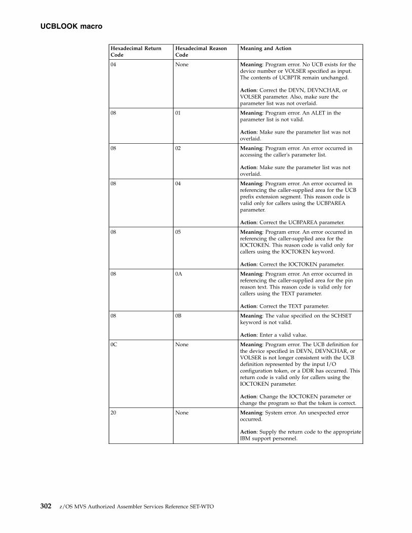
Hexadecimal ReturnCode
Hexadecimal ReasonCode
Meaning and Action
04 None Meaning: Program error. No UCB exists for thedevice number or VOLSER specified as input.The contents of UCBPTR remain unchanged.
Action: Correct the DEVN, DEVNCHAR, orVOLSER parameter. Also, make sure theparameter list was not overlaid.
08 01 Meaning: Program error. An ALET in theparameter list is not valid.
Action: Make sure the parameter list was notoverlaid.
08 02 Meaning: Program error. An error occurred inaccessing the caller's parameter list.
Action: Make sure the parameter list was notoverlaid.
08 04 Meaning: Program error. An error occurred inreferencing the caller-supplied area for the UCBprefix extension segment. This reason code isvalid only for callers using the UCBPAREAparameter.
Action: Correct the UCBPAREA parameter.
08 05 Meaning: Program error. An error occurred inreferencing the caller-supplied area for theIOCTOKEN. This reason code is valid only forcallers using the IOCTOKEN keyword.
Action: Correct the IOCTOKEN parameter.
08 0A Meaning: Program error. An error occurred inreferencing the caller-supplied area for the pinreason text. This reason code is valid only forcallers using the TEXT parameter.
Action: Correct the TEXT parameter.
08 0B Meaning: The value specified on the SCHSETkeyword is not valid.
Action: Enter a valid value.
0C None Meaning: Program error. The UCB definition forthe device specified in DEVN, DEVNCHAR, orVOLSER is not longer consistent with the UCBdefinition represented by the input I/Oconfiguration token, or a DDR has occurred. Thisreturn code is valid only for callers using theIOCTOKEN parameter.
Action: Change the IOCTOKEN parameter orchange the program so that the token is correct.
20 None Meaning: System error. An unexpected erroroccurred.
Action: Supply the return code to the appropriateIBM support personnel.
UCBLOOK macro
302 z/OS MVS Authorized Assembler Services Reference SET-WTO

UCBLOOK - List formUse the list form of the UCBLOOK macro together with the execute form forapplications that require reentrant code. The list form of the macro defines an areaof storage that the execute form uses for storing the parameters.
SyntaxThis macro is an alternative list form macro, and requires a different technique forusing the list form as compared to the conventional list form macros.
The list form of the UCBLOOK macro is written as follows:
Syntax Description
name name: Symbol. Begin name in column 1.
� One or more blanks must precede UCBLOOK
UCBLOOK
� One or more blanks must follow UCBLOOK
,PLISTVER=IMPLIED_VERSION
,PLISTVER=MAX Default: IMPLIED_VERSION
,PLISTVER=plistver plistver: 2
MF=(L,list addr) list addr: symbol.
MF=(L,list addr,attr) attr: 1- to 60-character input string.
MF=(L,list addr,0D) Default: 0D
ParametersThe parameters are explained under the standard form of the UCBLOOK macrowith the following exceptions:
MF=(L,list addr)MF=(L,list addr,attr)MF=(L,list addr,0D)
Specifies the list form of the UCBLOOK macro.
The list addr parameter specifies the address of the storage area for theparameter list.
attr is an optional 1- to 60-character input string, which can contain any valuethat is valid on an assembler DS pseudo-op. You can use this parameter toforce boundary alignment of the parameter list. If you do not code attr, thesystem provides a value of 0D, which forces the parameter list to adoubleword boundary.
UCBLOOK macro
Chapter 25. UCBLOOK — Obtain addresses of UCB segments 303

UCBLOOK - Execute formUse the execute form of the UCBLOOK macro together with the list form forapplications that require reentrant code. The execute form of the macro stores theparameters into the storage area defined by the list form.
SyntaxThe execute form of the UCBLOOK macro is written as follows:
Syntax Description
name name: Symbol. Begin name in column 1.
� One or more blanks must precede UCBLOOK
UCBLOOK
� One or more blanks must follow UCBLOOK
,SCHSET=xschset xschset RS-type address or register (2) - (12).
,SCHSET=0 Default: 0
DEVN=devn addr devn addr: RS-type address or register (2) - (12).
DEVNCHAR=devnchar addr devnchar addr: RS-type address or register (2) - (12).
VOLSER=volser addr volser addr: RS-type address or register (2) - (12).
LDEVNCHAR=xldevnchar xldevnchar RS-type address or register (2) - (12).
,UCBPTR=ucbptr addr ucbptr addr: RS-type address or register (2) - (12).
,UCBCXPTR=ucbcxptr addr ucbcxptr addr: RS-type address or register (2) - (12).
,UCBPXPTR=ucbpxptr addr ucbpxptr addr: RS-type address or register (2) - (12).
,UCBPAREA=ucbparea addr ucbparea addr: RX-type address or register (2) - (12).
,UCBPAREA=NONE Default: NONE
,LOC=BELOW Default: BELOW
,LOC=ANY
,PIN
,NOPIN Note: TEXT and PTOKEN are required with PIN and are not valid withNOPIN.
,TEXT=text addr text addr: RX-type address
UCBLOOK macro
304 z/OS MVS Authorized Assembler Services Reference SET-WTO
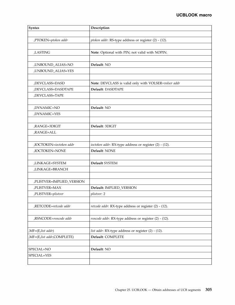
Syntax Description
,PTOKEN=ptoken addr ptoken addr: RS-type address or register (2) - (12).
,LASTING Note: Optional with PIN; not valid with NOPIN.
,UNBOUND_ALIAS=NO Default: NO
,UNBOUND_ALIAS=YES
,DEVCLASS=DASD Note: DEVCLASS is valid only with VOLSER=volser addr
,DEVCLASS=DASDTAPE Default: DASDTAPE
,DEVCLASS=TAPE
,DYNAMIC=NO Default: NO
,DYNAMIC=YES
,RANGE=3DIGIT Default: 3DIGIT
,RANGE=ALL
,IOCTOKEN=ioctoken addr ioctoken addr: RX-type address or register (2) - (12).
,IOCTOKEN=NONE Default: NONE
,LINKAGE=SYSTEM Default SYSTEM
,LINKAGE=BRANCH
,PLISTVER=IMPLIED_VERSION
,PLISTVER=MAX Default: IMPLIED_VERSION
,PLISTVER=plistver plistver: 2
,RETCODE=retcode addr retcode addr: RX-type address or register (2) - (12).
,RSNCODE=rsncode addr rsncode addr: RX-type address or register (2) - (12).
,MF=(E,list addr) list addr: RX-type address or register (2) - (12).
,MF=(E,list addr,COMPLETE) Default: COMPLETE
SPECIAL=NO Default: NO
SPECIAL=YES
UCBLOOK macro
Chapter 25. UCBLOOK — Obtain addresses of UCB segments 305

ParametersThe parameters are explained under the standard form of the UCBLOOK macrowith the following exceptions:
,MF=(E,list addr),MF=(E,list addr,COMPLETE)
Specifies the execute form of the UCBLOOK macro.
The list addr parameter specifies the address of the storage area for theparameter list. COMPLETE specifies that the system is to check for requiredparameters and supply defaults for optional parameters that were notspecified.
UCBLOOK macro
306 z/OS MVS Authorized Assembler Services Reference SET-WTO

Chapter 26. UCBPIN — Pinning or unpinning a UCB
DescriptionPinning a UCB ensures that the UCB cannot be deleted while a program is in theprocess of looking at a UCB. Programs that pin a UCB are also responsible forunpinning it once the UCB is no longer subject to processing.
Authorized programs that obtain UCB addresses, either through UCB services orother means, can use the UCBPIN macro to pin and unpin UCBs. Pinning andunpinning should be done any time a UCB is used, unless one of the following istrue:v The caller is running in an environment where dynamic configuration changes
cannot occur.v The caller can otherwise guarantee that the UCB will not be deleted. (The device
is allocated.)
EnvironmentThe requirements for the caller are:
Environmental factor RequirementMinimum authorization: Supervisor state or PKM keys 0-7.
For LINKAGE=BRANCH, all of the following:
v Supervisor state with key 0
v 31-bit addressing mode
v Primary ASC mode
v Parameter list and any data areas it points to must be infixed storage or, if the caller is disabled, in disabledreference (DREF) storage.
Dispatchable unit mode: Task or SRBCross memory mode: PASN=HASN=SASN or PASN¬=HASN¬=SASNAMODE: 24- or 31-bitASC mode: Primary or access register (AR)Interrupt status: Enabled or disabled for I/O and external interruptsLocks: No requirementControl parameters: Must be in the primary address space or be in an
address/data space that is addressable through a publicentry on the caller's dispatchable unit access list (DU-AL)
Programming requirementsIf the program is in AR mode, issue the SYSSTATE ASCENV=AR macro beforeUCBPIN. SYSSTATE ASCENV=AR tells the system to generate code appropriatefor AR mode.
RestrictionsNone.
© Copyright IBM Corp. 1988, 2017 307

Register informationAfter the caller issues the macro, the system might use some registers as workregisters or might change the contents of some registers. When the system returnscontrol to the caller, the contents of these registers are not the same as they werebefore the macro was issued. Therefore, if the caller depends on these registerscontaining the same value before and after issuing the macro, the caller must savethese registers before issuing the macro and restore them after the system returnscontrol.
When control returns to the caller, the general purpose registers (GPRs) contain:
RegisterContents
0 Reason code if GPR 15 contains a return code of 08; otherwise, used as awork register by the system
1 Used as a work register by the system
2-13 Unchanged
14 Used as a work register by the system
15 Return code
When control returns to the caller, the access registers (ARs) contain:
RegisterContents
0-1 Used as work registers by the system
2-13 Unchanged
14-15 Used as work registers by the system
Performance implicationsNone.
SyntaxThe standard form of the UCBPIN macro is written as follows:
Syntax Description
name name: Symbol. Begin name in column 1.
� One or more blanks must precede UCBPIN
UCBPIN
� One or more blanks must follow UCBPIN
PIN
UNPIN Note: See the table following this diagram for valid parametercombinations.
UCBPIN macro
308 z/OS MVS Authorized Assembler Services Reference SET-WTO

Syntax Description
,PTOKEN=ptoken addr ptoken addr: RS-type address or register (2) - (12).
,UCBPTR=ucbptr addr ucbptr addr: RS-type address or register (2) - (12).
,TEXT=text addr text addr: RX-type address
,LASTING
,IOCTOKEN=ioctoken addr ioctoken addr: RX-type address or register (2) - (12).
,RETCODE=retcode addr retcode addr: RX-type address or register (2) - (12).
,RSNCODE=rsncode addr rsncode addr: RX-type address or register (2) - (12).
,LINKAGE=SYSTEM Default: SYSTEM
,LINKAGE=BRANCH
,TO=xto xto: RS-type address or register (2) - (12).
,FROM=xfrom xfrom: RS-type address or register (2) - (12).
,RETCODE=retcode addr retcode addr: RX-type address or register (2) - (12).
,RSNCODE=rsncode addr rsncode addr: RX-type address or register (2) - (12).
,LINKAGE=SYSTEM Default: SYSTEM
,LINKAGE=BRANCH
The following table shows how other parameters may be used with PIN andUNPIN.
Parameters PIN UNPIN
PTOKEN required required
UCBPTR required not valid
TEXT required not valid
LASTING optional not valid
IOCTOKEN optional not valid
LINKAGE optional optional
RETCODE optional optional
UCBPIN macro
Chapter 26. UCBPIN — Pinning or unpinning a UCB 309

Parameters PIN UNPIN
RSNCODE optional optional
Parameters PIN UNPIN
PTOKEN required required
UCBPTR required not valid
TEXT required not valid
LASTING optional not valid
IOCTOKEN optional not valid
LINKAGE optional optional
RETCODE optional optional
RSNCODE optional optional
TO not valid not valid
FROM not valid not valid
ParametersThe parameters are explained as follows:
PIN UNPIN
Specifies whether the UCB is to be pinned or unpinned.
,PTOKEN=ptoken addrSpecifies the address of an 8-character field used to contain the pin token. ForPIN requests, PTOKEN specifies an output field that receives the pin token forthe UCB that is to be pinned. For UNPIN requests, PTOKEN specifies an inputfield that contains the pin token for the UCB that is to be unpinned; this tokenmust match the one that was returned on the corresponding PIN request.UCBPIN will reset PTOKEN to binary zeros if the UNPIN function issuccessful.
,UCBPTR=ucbptr addrSpecifies the address of a pointer containing the address of the UCB commonsegment for the UCB that is to be pinned.
,TEXT=text addrSpecifies the address of a 58-character input field containing text thatdocuments the reason for the PIN request. If the pin request remainsoutstanding during a request for a configuration change that would delete thisUCB, the text specified by the TEXT parameter will be displayed in a messageidentifying the reason for a configuration change failure.
,LASTINGSpecifies that the UCB will not be unpinned automatically by the system at thetime of termination of the task or address space with which the pin isassociated.
When you code LASTING, the system cannot dynamically delete the UCB untilyour program issues UCBPIN with the UNPIN parameter.
,IOCTOKEN=ioctoken addrSpecifies the address of a 48-character area that contains the MVS I/Oconfiguration token that you supply to UCBPIN. You can obtain this token by
UCBPIN macro
310 z/OS MVS Authorized Assembler Services Reference SET-WTO

issuing the IOCINFO macro, which is described in z/OS MVS Programming:Assembler Services Reference ABE-HSP. If the I/O configuration token that iscurrent when UCBPIN is invoked does not match the token specified as inputby ioctoken addr, the caller will be notified through a return code.
If the input IOCTOKEN (specified by ioctoken addr) is set to binary zeros,UCBPIN will set IOCTOKEN to the current I/O configuration token.
,RETCODE=retcode addrSpecifies the fullword location where the system is to store the return code.The return code is also in GPR 15.
,RSNCODE=rsncode addrSpecifies the fullword location where the system is to store the reason code.The reason code is also in GPR 0 if the return code is X'08'.
,LINKAGE=SYSTEM,LINKAGE=BRANCH
Specifies the type of call that the system is to generate:v SYSTEM: Specifies a Program Call (PC)v BRANCH: Specifies a Branch entry
LINKAGE=BRANCH is intended for performance-sensitive programs.
Return and reason codesWhen control returns from UCBPIN, GPR 15 (and retcode addr, if you codedRETCODE) contains one of the following return codes:
Table 41. Return Codes for the UCBPIN Macro
Hexadecimal ReturnCode
Meaning
00 Meaning: UCBPIN completed successfully. For PIN requests, the UCB hasbeen pinned and the pin token has been returned in PTOKEN. For UNPINrequests, the UCB has been unpinned and PTOKEN has been reset tobinary zeros.
08 Meaning: There is an error in the caller's parameters, as explained by thehexadecimal reason code that accompanies this return code. The reasoncode is in GPR 0 (and in rsncode addr, if you coded RSNCODE).
Reason CodeMeaning
01 An ALET in the parameter list is not valid; the caller might haveinadvertently written over an area in the parameter list.
02 An error occurred in accessing the caller's parameter list.
03 The UCB address provided by the caller does not represent avalid UCB.
04 The PTOKEN supplied as input on an UNPIN request does notrepresent a valid pin token.
05 An error occurred in referencing the user-supplied work area forthe IOCTOKEN. This reason code is valid only for callers usingthe IOCTOKEN keyword.
0A An error occurred in referencing the user-supplied work area forthe pin reason text. This reason code is valid only for callersusing the TEXT keyword.
0C Meaning: The UCB definition is not consistent with the input configurationtoken, or a DDR has occurred. This return code is valid only for callersusing the IOCTOKEN keyword.
20 Meaning: An unexpected error occurred.
UCBPIN macro
Chapter 26. UCBPIN — Pinning or unpinning a UCB 311

UCBPIN - List formUse the list form of the UCBPIN macro together with the execute form forapplications that require reentrant code. The list form of the macro defines an areaof storage that the execute form uses for storing the parameters.
SyntaxThis macro is an alternative list form macro, and requires a different technique forusing the list form as compared to the conventional list form macros.
The list form of the UCBPIN macro is written as follows:
Syntax Description
name name: Symbol. Begin name in column 1.
� One or more blanks must precede UCBPIN
UCBPIN
� One or more blanks must follow UCBPIN
MF=(L,list addr) list addr: Symbol.
MF=(L,list addr,attr) attr: 1- to 60-character input string.
MF=(L,list addr,0D) Default: 0D
ParametersThe parameters are explained as follows:
MF=(L,list addr)MF=(L,list addr,attr)MF=(L,list addr,0D)
Specifies the list form of the UCBPIN macro.
The list addr parameter specifies the address of the storage area for theparameter list.
attr is an optional 1- to 60-character input string, which can contain any valuethat is valid on an assembler DS pseudo-op. You can use this parameter toforce boundary alignment of the parameter list. If you do not code attr, thesystem provides a value of 0D, which forces the parameter list to adoubleword boundary.
UCBPIN - Execute formUse the execute form of the UCBPIN macro together with the list form forapplications that require reentrant code. The execute form of the macro stores theparameters into the storage area defined by the list form.
UCBPIN macro
312 z/OS MVS Authorized Assembler Services Reference SET-WTO

SyntaxThe execute form of the UCBPIN macro is written as follows:
Syntax Description
name name: Symbol. Begin name in column 1.
� One or more blanks must precede UCBPIN
UCBPIN
� One or more blanks must follow UCBPIN
PIN
UNPIN Note: See the table following this diagram for valid parametercombinations.
,PTOKEN=ptoken addr ptoken addr: RS-type address or register (2) - (12).
,UCBPTR=ucbptr addr ucbptr addr: RS-type address or register (2) - (12).
,TEXT=text addr text addr: RX-type address
,LASTING
,IOCTOKEN=ioctoken addr ioctoken addr: RX-type address or register (2) - (12).
,TO=xto xto: RS-type address or register (2) - (12).
,FROM=xfrom xfrom: RS-type address or register (2) - (12).
,RETCODE=retcode addr retcode addr: RX-type address or register (2) - (12).
,RSNCODE=rsncode addr rsncode addr: RX-type address or register (2) - (12).
,LINKAGE=SYSTEM Default: SYSTEM
,LINKAGE=BRANCH
,RETCODE=retcode addr retcode addr: RX-type address or register (2) - (12).
,RSNCODE=rsncode addr rsncode addr: RX-type address or register (2) - (12).
,LINKAGE=SYSTEM Default: SYSTEM
UCBPIN macro
Chapter 26. UCBPIN — Pinning or unpinning a UCB 313

Syntax Description
,LINKAGE=BRANCH
,MF=(E,list addr) list addr: RX-type address or register (2) - (12).
,MF=(E,list addr,COMPLETE) Default: COMPLETE
The following table shows how other parameters may be used with PIN andUNPIN.
Parameters PIN UNPIN
PTOKEN required required
UCBPTR required not valid
TEXT required not valid
LASTING optional not valid
IOCTOKEN optional not valid
LINKAGE optional optional
RETCODE optional optional
RSNCODE optional optional
MF required required
TO not valid not valid
FROM not valid not valid
ParametersThe parameters are explained under the standard form of the UCBPIN macro withthe following exceptions:
,MF=(E,list addr),MF=(E,list addr,COMPLETE)
Specifies the execute form of the UCBPIN macro.
The list addr parameter specifies the address of the storage area for theparameter list. COMPLETE specifies that the system is to check for requiredparameters and supply defaults for optional parameters that were notspecified.
UCBPIN macro
314 z/OS MVS Authorized Assembler Services Reference SET-WTO

Chapter 27. UCBSCAN — Scan UCBs
DescriptionUse the UCBSCAN macro to scan unit control blocks (UCBs) and return a copy ofa UCB or a UCB address on each invocation.
Two types of scans are available with UCBSCAN: A scan of all UCBs, and a scanof all UCBs within a particular device class. For each type of scan, the caller mayoptionally:v Restrict the scan to UCBs defined as static or installation-static.v Restrict the scan to UCBs with 3-digit device numbers.v Restrict the scan to addresses of below 16 megabyte UCBsv Request alias UCBs for a parallel access volume.v Specify the device number with which the scan should begin.
UCBSCAN presents the UCBs in ascending device number order. UCBSCANprovides two options as follows:
COPY On each invocation, UCBSCAN returns a copy of requested UCB segmentsand data in caller-supplied areas.
AddressOn each invocation, UCBSCAN returns the address of the UCB, theaddress of requested UCB segments, and, optionally, a copy of the UCBprefix extension segment. The caller can specify whether the scan includesabove 16 megabyte UCBs or only below 16 megabyte UCBs. The callermust pin and unpin the UCB unless one of the following is true:v The caller is running in an environment where dynamic configuration
changes cannot occurv The caller can otherwise guarantee that the UCB will not be deleted.
See z/OS MVS Programming: Authorized Assembler Services Guide forinformation on pinning UCBs.
LINKAGE=BRANCH is intended for performance-sensitive programs.
© Copyright IBM Corp. 1988, 2017 315

EnvironmentThe requirements for the caller are:
Environmental factor RequirementMinimum authorization: For the COPY parameter: Problem state with any PSW key
For the ADDRESS parameter: Supervisor state or PKMallowing key 0-7
For the LINKAGE=BRANCH parameter, all of the following:
v Supervisor state with key 0
v 31-bit addressing mode
v Primary ASC mode
v Parameter list and any data areas it points to must be infixed storage or, if the caller is disabled, in disabledreference (DREF) storage.
Dispatchable unit mode: Task or SRBCross memory mode: Any PASN, any HASN, any SASN.AMODE: 24- or 31-bit.ASC mode: Primary or access register (AR).Interrupt status: Enabled or disabled for I/O and external interrupts
Locks: The caller may hold locks, but is not required to hold any.Control parameters: Must be in the primary address space or, for AR-mode
callers, must be in an address/data space that is addressablethrough a public entry on the caller's dispatchable unitaccess list (DU-AL).
Programming requirementsIf in AR mode, issue SYSSTATE ASCENV=AR before issuing UCBSCAN.
RestrictionsNone.
Input register informationBefore issuing the UCBSCAN macro, the caller does not have to place anyinformation into any register unless using it in register notation for a particularparameter, or using it as a base register.
Output register informationWhen control returns to the caller, the general purpose registers (GPRs) contain:
RegisterContents
0 Reason code if GPR 15 contains a return code of 04 or 08; otherwise, usedas a work register by the system
1 Used as a work register by the system
2-13 Unchanged
14 Used as a work register by the system
15 Return code
UCBSCAN macro
316 z/OS MVS Authorized Assembler Services Reference SET-WTO

When control returns to the caller, the access registers (ARs) contain:
RegisterContents
0-1 Used as work registers by the system
2-13 Unchanged
14-15 Used as work registers by the system
Performance implicationsNone.
ParametersThe parameters are explained as follows:
COPYSpecifies that a copy of the UCB is to be obtained. See z/OS HCD Planning fora list of the MVS services that accept a UCB copy.
Note: When you issue UCBSCAN to obtain a UCB copy, the UCBID field inthe copy is set to x‘CC’.
,WORKAREA=workarea addrSpecifies the address of a 100-character work area used by the UCBSCANservice. The caller must initialize this work area to binary zeros before startinga UCB scan. On subsequent invocations of UCBSCAN within the same scan,the caller must leave the contents of this work area unchanged.
,UCBAREA=ucbarea addrSpecifies the address of a 48-character storage area that will receive a copy ofthe UCB common segment and the UCB device-dependent segment. See z/OSHCD Planning for a list of the MVS services that accept a UCB copy.
The caller does not need to initialize this area. Use the IEFUCBOB mappingmacro to map the area. The contents of certain fields in the copy are:v The UCBEXTP field contains either:
– The address of the CMXTAREA, if CMXTAREA is below 16 MB– 0, if CMXTAREA is above 16 MB or if the CMXTAREA parameter is not
specifiedv The UCBNXUCB field is 0, because this field is not valid in the UCB copy.v Address fields in the copy might not contain valid addresses, so do not use
these addresses to reference the data areas they point to.
,CMXTAREA=cmxtarea addr,CMXTAREA=NONE
Specifies the address of a 32-character storage area that will receive a copy ofthe UCB common extension segment. See z/OS HCD Planning for a list of theMVS services that accept a UCB copy and require this segment as part of aUCB copy.
Use the UCBCMEXT DSECT in the IEFUCBOB mapping macro to map thearea. If the CMXTAREA area is below 16 MB, the UCBEXTP field in theUCBAREA area contains the address of the CMXTAREA area, If theCMXTAREA area is above 16 MB, the caller must explicitly supply the addressof the CMXTAREA area because the UCBEXTP field will contain 0.
The UCBIEXT field contains 0 because this field is not valid in the UCB copy.
UCBSCAN macro
Chapter 27. UCBSCAN — Scan UCBs 317

The UCBCLEXT field contains the address of the DCEAREA if the UCB has adevice class extension and the caller specified the DCEAREA parameter.Otherwise, the field contains 0.
,UCBPAREA=ucbparea addr,UCBPAREA=NONE
Specifies the address of a 48-character storage area that will receive a copy ofthe UCB prefix extension segment. This keyword is required ifSUBCHANNELSET=ALL is specified. The area can be mapped by theIOSDUPI mapping macro.
,DCEAREA=dcearea addr,DCEAREA=NONE
Specifies the address of a storage area that will receive a copy of the UCBdevice class extension segment. See z/OS HCD Planning for a list of the MVSservices that accept a UCB copy and require this segment as part of a UCBcopy.
Note: If DCEAREA=NONE is coded, then DCELEN=0 must be coded. IfDCEAREA=NONE is defaulted, then DCELEN does not have to be coded.
,DCELEN=length addrSpecifies the address of a 2-byte field that contains the length of the areaspecified by DCEAREA. The length specified must be 1 through 256 bytes.DCELEN is required with DCEAREA.
,VOLSER=volser addr,VOLSER=NONE
Specifies the address of a 6-character field that indicates, in EBCDIC, thevolume serial number of the device for which a UCB copy is to be obtained.
,DEVNCHAR=devnchar addrSpecifies the address of a 4-character field that is to receive the EBCDIC devicenumber associated with the UCB copy.
,DEVN=devn addr,DEVN=0
Specifies (DEVN=devn addr) an input halfword that contains, in binary form,the device number with which the scan is to begin. The default, DEVN=0,starts the scan with the first UCB.
,SUBCHANNELSET=ID,SUBCHANNELSET=ALL
,SUBCHANNELSET=IDIndicates the UCB scan is based on one subchannel set. DEFAULT: ID
,SCHSET=xschsetSCHSET=0
Specifies the name (RS-type), or address in register (2)-(12), of an optionalbyte input that specifies a subchannel set for which the UCB scan is to beperformed. DEFAULT: 0.
,SUBCHANNELSET=ALLIndicates the UCB scan is based on all subchannel sets. DEFAULT: ID
,LDEVNCHAR=xldevncharIndicates the name (RS-type), or address in register (2)-(12), of an optional 5character output which is to contain the EBCDIC logical device numberassociated with the UCB copy.
UCBSCAN macro
318 z/OS MVS Authorized Assembler Services Reference SET-WTO

Note: A logical device number is represented by the 1-digit subchannel set idfollowed by a 4-digit device number, sdddd.
,DYNAMIC=NO,DYNAMIC=YES
Specifies whether the scan should be restricted to static and installation-staticUCBs (DYNAMIC=NO) or should also include dynamic UCBs(DYNAMIC=YES).
,RANGE=3DIGIT,RANGE=ALL
Specifies whether the scan should be restricted to UCBs with 3-digit devicenumbers (3DIGIT) or should also include UCBs with 4-digit device numbers(ALL).
,UNBOUND_ALIAS=NO,UNBOUND_ALIAS=YES,UNBOUND_ALIAS=ONLY
Specifies whether the scan should include unbound alias UCBs.
YES Include unbound alias UCBs
NO Do not include unbound alias UCBs
ONLY Include only unbound alias UCBs
Note: The UNBOUND_ALIAS function is intended for IOS use only.
SPECIAL=NOSPECIAL=YESSPECIAL=ONLY
Specifies whether the UCB is findable (SPECIAL=YES) or not (SPECIAL=NO).SPECIAL=ONLY should be used to scan for only special devices. Specialdevices are those UCBs that represent devices that are not PAV-alias devices inthe alternate subchannel set. The 3390S and 3390D device types are specialdevices.
,DEVCLASS=ALL,DEVCLASS=CHAR,DEVCLASS=COMM,DEVCLASS=CTC,DEVCLASS=DASD,DEVCLASS=DISP,DEVCLASS=TAPE,DEVCLASS=UREC
Specifies the device class that is to be scanned:
ALL Scans UCBs for all device classes
CHARScans UCBs for character reader device class
COMMScans UCBs for communications device class
CTC Scans UCBs for channel to channel device class
DASDScans UCBs for direct access device class
DISP Scans UCBs for display device class
TAPE Scans UCBs for tape device class
UCBSCAN macro
Chapter 27. UCBSCAN — Scan UCBs 319

UREC Scans UCBs for unit record device class
,DEVCID=devcid addrSpecifies the address of an 8-bit input field that contains the device class ID ofthe device class to be scanned. The value in this byte represents the third bytein the UCBTYP field of each device in the class.
If you specify DEVCID, only UCBs of the particular device class specified willbe presented, and the DEVCLASS parameter is ignored.
,IOCTOKEN=ioctoken addr,IOCTOKEN=NONE
Specifies the address of a 48-character storage area that contains the MVS I/Oconfiguration token. The caller can obtain this token by issuing the IOCINFOmacro, which is described in z/OS MVS Programming: Assembler ServicesReference ABE-HSP. If the I/O configuration token that is current whenUCBSCAN is invoked does not match the token whose address is supplied asinput by ioctoken addr, the caller will be notified through a return code.
If the input IOCTOKEN (specified by ioctoken addr) is set to binary zeros,UCBSCAN will set IOCTOKEN to the current I/O configuration token at thestart of the scan.
,LINKAGE=SYSTEM,LINKAGE=BRANCH
Specifies the type of call that should be generated:v SYSTEM: Specifies a Program Call (PC)v BRANCH: Specifies a Branch entry
LINKAGE=BRANCH is intended for performance-sensitive programs.
,PLISTVER=IMPLIED_VERSION,PLISTVER=MAX,PLISTVER=plistver
Specifies the version of the macro. PLISTVER determines which parameter listthe system generates. PLISTVER is an optional input parameter on all forms ofthe macro, including the list form. When using PLISTVER, specify it on allmacro forms used for a request and with the same value on all of the macroforms. The values are:v IMPLIED_VERSION, which is the lowest version that allows all parameters
specified on the request to be processed. If you omit the PLISTVERparameter, IMPLIED_VERSION is the default.
v MAX, if you want the parameter list to be the largest size currently possible.This size might grow from release to release and affect the amount ofstorage that your program needs.If you can tolerate the size change, IBM recommends that you alwaysspecify PLISTVER=MAX on the list form of the macro. Specifying MAXensures that the list-form parameter list is always long enough to hold allthe parameters you might specify on the execute form; in this way, MAXensures that the parameter list does not overwrite nearby storage.
v 1, if you use the currently available parameters.
To code, specify in this input parameter one of the following:v IMPLIED_VERSIONv MAXv A decimal value of 1
UCBSCAN macro
320 z/OS MVS Authorized Assembler Services Reference SET-WTO

,RETCODE=retcode addrSpecifies the fullword location where the system is to store the return code.The return code is also in GPR 15.
,RSNCODE=rsncode addrSpecifies the fullword location where the system is to store the reason code.The reason code is also in GPR 0.
Return and reason codesWhen control returns from USBSCAN, GPR 15 (and retcode addr, if you codedRETCODE) contains a return code and, for some return codes, GPR 0 (or rsncodeaddr, if you coded RSNCODE) contains a reason code.
Hexadecimal ReturnCode
Hexadecimal ReasonCode Meaning and Action
00 None Meaning: UCBSCAN completed successfully.
Action: None.
04 01 Meaning: UCBSCAN processing ended. All UCBsthat met the search criteria have been presentedto the caller. The contents of UCBAREA areunchanged, and WORKAREA has been reset tobinary zeros.
Action: None.
08 01 Meaning: Program error. A caller in AR modespecified an ALET that was not valid.
Action: Correct the ALET and reissue the macro.Possibly the caller wrote over an area in theparameter list; look for this error.
08 02 Meaning: Program error. An error occurred whenthe system tried to access the caller's parameterlist.
Action: Ensure that you have met theenvironmental requirements for the macro, andreissue the macro.
08 03 Meaning: Program error. An error occurred inreferencing the caller-supplied area for the UCBcopy; the area was specified in the UCBAREAparameter.
Action: Correct the UCBAREA parameter.
08 04 Meaning: Program error. An error occurred inreferencing the caller-supplied area for the UCBprefix extension segment data. This reason codeis valid only for callers using the UCBPAREAparameter.
Action: Correct the UCBPAREA parameter.
08 05 Meaning: Program error. An error occurred whenthe system referenced the caller-supplied areaspecified in the IOCTOKEN parameter. Thisreason code is valid only for callers using theIOCTOKEN parameter.
Action: Correct the IOCTOKEN parameter.
UCBSCAN macro
Chapter 27. UCBSCAN — Scan UCBs 321

Hexadecimal ReturnCode
Hexadecimal ReasonCode Meaning and Action
08 08 Meaning: Program error. An error occurred inreferencing the caller-supplied work areaspecified in the WORKAREA parameter.
Action: Correct the WORKAREA parameter.
08 09 Meaning: Program error. An error occurred inreferencing the caller-supplied CMXTAREA area.This reason code is valid only for callers usingthe CMXTAREA parameter.
Action: Correct the CMXTAREA parameter.
08 0B Meaning: Program error. An error occurred inreferencing the caller-supplied DCEAREA area.This reason code is valid only for callers usingthe DCEAREA parameter.
Action: Correct the DCEAREA parameter.
08 0C Meaning: Program error. The caller specified avolume serial number that is not valid. (Note thatbinary zeros are not considered valid.) Thisreason code is valid only for callers using theVOLSER parameter.
Action: Correct the VOLSER parameter.
08 0D Meaning: Program error. For the DCEAREAtoken, the caller specified a length that isnegative, is zero, or exceeds 256 bytes. Thisreason code is valid only for callers using theDCELEN parameter.
Action: Correct the DCELEN parameter.
08 0E Meaning: The value specified on the SCHSETkeyword is not valid.
Action: Correct the SCHSET value.
0C None Meaning: Environmental error. The I/Oconfiguration has changed, so that the I/Oconfiguration token supplied through theIOCTOKEN parameter is not current. This returncode is valid only for callers using theIOCTOKEN parameter.
Action: Obtain the current I/O configurationtoken by issuing an IOCINFO macro or bysetting the input IOCTOKEN parameter in theUCBINFO macro to zero. Start the scan from thebeginning.
20 None Meaning: System error. An unexpected erroroccurred.
Action: Supply the return code to the appropriateIBM support personnel.
UCBSCAN COPY
SyntaxThe standard form of the COPY function of the UCBSCAN macro is written asfollows:
UCBSCAN macro
322 z/OS MVS Authorized Assembler Services Reference SET-WTO

Syntax Description
name name: Symbol. Begin name in column 1.
� One or more blanks must precede UCBSCAN.
UCBSCAN
� One or more blanks must follow UCBSCAN.
COPY Default: COPY
,WORKAREA=workarea addr workarea addr: RX-type address or register (2) - (12).
,UCBAREA=ucbarea addr ucbarea addr: RX-type address or register (2) - (12).
,CMXTAREA=cmxtarea addr cmxtarea addr: RX-type address or register (2) - (12).
,CMXTAREA=NONE Default: NONE
,UCBPAREA=ucbparea addr ucbparea addr: RX-type address or register (2) - (12).
,UCBPAREA=NONE Default: NONE
,DCEAREA=dcearea addr dcearea addr: RX-type address or register (2) - (12).
,DCEAREA=NONE Default: NONE
,DCELEN=length addr length addr: RS-type address or register (2) - (12).
Note: DCELEN is valid only with DCEAREA and is required withDCEAREA.
,VOLSER=volser addr volser addr: RS-type address or register (2) - (12).
,VOLSER=NONE Default: NONE
,DEVNCHAR=devnchar addr devnchar addr: RS-type address or register (2) - (12).
,LDEVNCHAR=xldevnchar xldevnchar: RS-type address or register (2) - (12).
,DEVN=devn addr devn addr: RS-type address or register (2) - (12).
,DEVN=0 Default: 0
,SUBCHANNELSET=ID
,SCHSET=xschset xschset RS-type address or register (2) - (12).
,SCHSET=0 Default: 0
,SUBCHANNELSET=ALL
UCBSCAN macro
Chapter 27. UCBSCAN — Scan UCBs 323

Syntax Description
,DYNAMIC=NO Default: NO
,DYNAMIC=YES
,RANGE=3DIGIT Default: 3DIGIT
,RANGE=ALL
,UNBOUND_ALIAS=NO Default: NO
,UNOUND_ALIAS=YES
,DEVCLASS=ALL Default: ALL
,DEVCLASS=CHAR
,DEVCLASS=COMM
,DEVCLASS=CTC
,DEVCLASS=DASD
,DEVCLASS=DISP
,DEVCLASS=TAPE
,DEVCLASS=UREC
,DEVCID=devcid addr devcid addr: RS-type address
,DEVCID=0 Default: 0
,IOCTOKEN=ioctoken addr ioctoken addr: RX-type address or register (2) - (12).
,IOCTOKEN=NONE Default: NONE
,LINKAGE=SYSTEM Default: LINKAGE=SYSTEM
,LINKAGE=BRANCH
,PLISTVER=IMPLIED_VERSION
,PLISTVER=MAX Default: IMPLIED_VERSION
,PLISTVER=plistver plistver: 1
,RETCODE=retcode addr retcode addr: RX-type address or register (2) - (12).
,RSNCODE=rsncode addr rsncode addr: RX-type address or register (2) - (12).
UCBSCAN COPY - List formUse the list form of the UCBSCAN macro together with the execute form forapplications that require reentrant code. The list form of the macro defines an areaof storage that the execute form uses for storing the parameters.
UCBSCAN macro
324 z/OS MVS Authorized Assembler Services Reference SET-WTO

SyntaxThis macro is an alternative list form macro, and requires a different technique forusing the list form as compared to the conventional list form macros. See“Alternative list form macros” on page 13 for further information.
The list form of the COPY function of the UCBSCAN macro is written as follows:
Syntax Description
name name: Symbol. Begin name in column 1.
� One or more blanks must precede UCBSCAN.
UCBSCAN
� One or more blanks must follow UCBSCAN.
,PLISTVER=IMPLIED_VERSION
,PLISTVER=MAX Default: IMPLIED_VERSION
,PLISTVER=plistver plistver: 1
MF=(L,list addr) list addr: Symbol.
MF=(L,list addr,attr) attr: 1- to 60-character input string.
MF=(L,list addr,0D) Default: 0D
ParametersThe parameters are explained under that standard form of the UCBSCAN macrowith the following exceptions:
MF=(L,list addr)MF=(L,list addr,attr)MF=(L,list addr,0D)
Specifies the list form of the UCBSCAN macro.
The list addr parameter specifies the address of the storage area for theparameter list.
attr is an optional 1- to 60-character input string, which can contain any valuethat is valid on an assembler DS pseudo-op. You can use this parameter toforce boundary alignment of the parameter list. If you do not code attr, thesystem provides a value of 0D, which forces the parameter list to adoubleword boundary.
UCBSCAN COPY - Execute formUse the execute form of the UCBSCAN macro together with the list form forapplications that require reentrant code. The execute form of the macro stores theparameters into the storage area defined by the list form.
UCBSCAN macro
Chapter 27. UCBSCAN — Scan UCBs 325

SyntaxThe execute form of the COPY function of the UCBSCAN macro is written asfollows:
Syntax Description
name name: Symbol. Begin name in column 1.
� One or more blanks must precede UCBSCAN.
UCBSCAN
� One or more blanks must follow UCBSCAN.
COPY Default: COPY
,WORKAREA=workarea addr workarea addr: RX-type address or register (2) - (12).
,UCBAREA=ucbarea addr ucbarea addr: RX-type address or register (2) - (12).
,CMXTAREA= cmxtarea addr cmxtarea addr: RX-type address or register (2) - (12).
,CMXTAREA=NONE Default: NONE
,UCBPAREA=ucbparea addr ucbparea addr: RX-type address or register (2) - (12).
,UCBPAREA=NONE Default: NONE
,DCEAREA= dcearea addr dcearea addr: RX-type address or register (2) - (12).
,DCEAREA=NONE Default: NONE
,DCELEN=length addr length addr: RS-type address or register (2) - (12).
Note: DCELEN is valid only with DCEAREA and is required withDCEAREA.
,VOLSER=volser addr volser addr: RS-type address or register (2) - (12).
,VOLSER=NONE Default: NONE
,DEVNCHAR=devnchar addr devnchar addr: RS-type address or register (2) - (12).
,DEVN=devn addr devn addr: RS-type address or register (2) - (12).
,DEVN=0 Default: 0
,SUBCHANNELSET=ID
UCBSCAN macro
326 z/OS MVS Authorized Assembler Services Reference SET-WTO

Syntax Description
,SCHSET=xschset xschset RS-type address or register (2) - (12).
,SCHSET=0 Default: 0
,SUBCHANNELSET=ALL
,DYNAMIC=NO Default: NO
,DYNAMIC=YES
,RANGE=3DIGIT Default: 3DIGIT
,RANGE=ALL
,UNBOUND_ALIAS=NO Default: NO
,UNBOUND_ALIAS=YES
,UNBOUND_ALIAS=ONLY
,DEVCLASS=ALL Default: ALL
,DEVCLASS=CHAR
,DEVCLASS=COMM
,DEVCLASS=CTC
,DEVCLASS=DASD
,DEVCLASS=DISP
,DEVCLASS=TAPE
,DEVCLASS=UREC
,DEVCID=devcid addr devcid addr: RS-type address
,DEVCID=0 Default: 0
,IOCTOKEN=ioctoken addr ioctoken addr: RX-type address or register (2) - (12).
,IOCTOKEN=NONE Default: NONE
,LINKAGE=SYSTEM Default: LINKAGE=SYSTEM
,LINKAGE=BRANCH
,PLISTVER=IMPLIED_VERSION
,PLISTVER=MAX Default: IMPLIED_VERSION
,PLISTVER=plistver plistver: 1
,RETCODE=retcode addr retcode addr: RX-type address or register (2) - (12).
,RSNCODE=rsncode addr rsncode addr: RX-type address or register (2) - (12).
,MF=(E,list addr) list addr: RX-type address or register (2) - (12).
UCBSCAN macro
Chapter 27. UCBSCAN — Scan UCBs 327

Syntax Description
,MF=(E,list addr,COMPLETE) Default: COMPLETE
ParametersThe parameters are explained under the standard form of the COPY function ofthe UCBSCAN macro with the following exceptions:
,MF=(E,list addr),MF=(E,list addr,COMPLETE)
Specifies the execute form of the UCBSCAN macro.
The list addr parameter specifies the address of the storage area for theparameter list.
COMPLETE specifies that the system is to check for required parameters andsupply defaults for optional parameters that were not specified.
UCBSCAN ADDRESS
SyntaxThe standard form of the ADDRESS function of the UCBSCAN macro is written asfollows:
Syntax Description
name name: Symbol. Begin name in column 1.
� One or more blanks must precede UCBSCAN.
UCBSCAN
� One or more blanks must follow UCBSCAN.
ADDRESS Note: COPY is the default.
,WORKAREA=workarea addr workarea addr: RX-type address or register (2) - (12).
,UCBPTR=ucbptr addr ucbptr addr: RS-type address or register (2) - (12).
,UCBCXPTR=ucbcxptr addr ucbcxptr: RX-type address or register (2) - (12).
,UCBPXPTR=ucbpxptr addr ucbpxptr: RX-type address or register (2) - (12).
,LOC=BELOW Default: BELOW
,LOC=ANY
UCBSCAN macro
328 z/OS MVS Authorized Assembler Services Reference SET-WTO

Syntax Description
,PIN Note: TEXT and PTOKEN are required with PIN
,NOPIN
,TEXT=text addr: text addr: RX-type address
Note: Required with PIN, not valid with NOPIN.
,PTOKEN=ptoken addr: ptoken addr: RS-type address or register (2) - (12).
Note: Required with PIN, not valid with NOPIN.
,UCBPAREA=ucbparea addr ucbparea addr: RX-type address or register (2) - (12).
,UCBPAREA=NONE Default: NONE
,DEVN=devn addr devn addr: RS-type address or register (2) - (12).
,DEVN=0 Default: 0
,SUBCHANNELSET=ID
,SCHSET=xschset xschset RS-type address or register (2) - (12).
,SCHSET=0 Default: 0
,SUBCHANNELSET=ALL
,DYNAMIC=NO Default: NO
,DYNAMIC=YES
,RANGE=3DIGIT Default: 3DIGIT
,RANGE=ALL
,UNBOUND_ALIAS=NO Default: NO
,UNBOUND_ALIAS=YES
,UNBOUND_ALIAS=ONLY
,DEVCLASS=ALL Default: ALL
,DEVCLASS=CHAR
,DEVCLASS=COMM
,DEVCLASS=CTC
,DEVCLASS=DASD
,DEVCLASS=DISP
,DEVCLASS=TAPE
,DEVCLASS=UREC
,DEVCID=devcid addr devcid addr: RS-type address
UCBSCAN macro
Chapter 27. UCBSCAN — Scan UCBs 329

Syntax Description
,IOCTOKEN=ioctoken addr ioctoken addr: RX-type address or register (2) - (12).
,IOCTOKEN=NONE Default: NONE
,LINKAGE=SYSTEM Default: LINKAGE=SYSTEM
,LINKAGE=BRANCH
,PLISTVER=IMPLIED_VERSION
,PLISTVER=MAX Default: IMPLIED_VERSION
,PLISTVER=plistver plistver: 1 - 2
,RETCODE=retcode addr retcode addr: RX-type address or register (2) - (12).
,RSNCODE=rsncode addr rsncode addr: RX-type address or register (2) - (12).
ParametersThe parameters are explained as follows:
ADDRESSSpecifies that a UCB address is to be obtained.
,WORKAREA=workarea addrSpecifies the address of a 100-character work area that will be used by theUCBSCAN service. The caller must initialize this work area to binary zerosbefore starting a UCB scan. On subsequent invocations of UCBSCAN withinthe same scan, the caller must leave the contents of this work area unchanged.
,UCBPTR=ucbptr addrSpecifies the address of a pointer in which the address of the UCB commonsegment for the next UCB that meets the search criteria will be returned.
Use the UCBOB structure in the IEFUCBOB mapping macro to map the UCBcommon segment.
,UCBCXPTR=ucbcxptr addrSpecifies the address of a fullword field in which the system will return theaddress of the UCB common extension. Use the IEFUCBOB mapping macro tomap the UCB common extension segment.
,UCBPXPTR=ucbpxptr addrSpecifies the address of a fullword field in which the system will return theaddress of the UCB prefix extension. Use the IOSDUPFX mapping macro tomap the UCB prefix extension segment.
,LOC=BELOW,LOC=ANY
Specifies whether the scan should be restricted to below 16 megabyte UCBs(LOC=BELOW) or should also include above 16 megabyte UCBs (LOC=ANY).
,PIN
UCBSCAN macro
330 z/OS MVS Authorized Assembler Services Reference SET-WTO
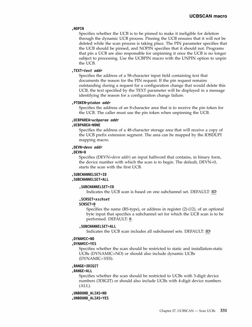
,NOPINSpecifies whether the UCB is to be pinned to make it ineligible for deletionthrough the dynamic UCB process. Pinning the UCB ensures that it will not bedeleted while the scan process is taking place. The PIN parameter specifies thatthe UCB should be pinned, and NOPIN specifies that it should not. Programsthat pin a UCB are also responsible for unpinning it once the UCB is no longersubject to processing. Use the UCBPIN macro with the UNPIN option to unpinthe UCB.
,TEXT=text addrSpecifies the address of a 58-character input field containing text thatdocuments the reason for the PIN request. If the pin request remainsoutstanding during a request for a configuration change that would delete thisUCB, the text specified by the TEXT parameter will be displayed in a messageidentifying the reason for a configuration change failure.
,PTOKEN=ptoken addrSpecifies the address of an 8-character area that is to receive the pin token forthe UCB. The caller must use the pin token when unpinning the UCB.
,UCBPAREA=ucbparea addr,UCBPAREA=NONE
Specifies the address of a 48-character storage area that will receive a copy ofthe UCB prefix extension segment. The area can be mapped by the IOSDUPImapping macro.
,DEVN=devn addr,DEVN=0
Specifies (DEVN=devn addr) an input halfword that contains, in binary form,the device number with which the scan is to begin. The default, DEVN=0,starts the scan with the first UCB.
,SUBCHANNELSET=ID,SUBCHANNELSET=ALL
,SUBCHANNELSET=IDIndicates the UCB scan is based on one subchannel set. DEFAULT: ID
,SCHSET=xschsetSCHSET=0
Specifies the name (RS-type), or address in register (2)-(12), of an optionalbyte input that specifies a subchannel set for which the UCB scan is to beperformed. DEFAULT: 0.
,SUBCHANNELSET=ALLIndicates the UCB scan includes all subchannel sets. DEFAULT: ID
,DYNAMIC=NO,DYNAMIC=YES
Specifies whether the scan should be restricted to static and installation-staticUCBs (DYNAMIC=NO) or should also include dynamic UCBs(DYNAMIC=YES).
,RANGE=3DIGIT,RANGE=ALL
Specifies whether the scan should be restricted to UCBs with 3-digit devicenumbers (3DIGIT) or should also include UCBs with 4-digit device numbers(ALL).
,UNBOUND_ALIAS=NO,UNBOUND_ALIAS=YES
UCBSCAN macro
Chapter 27. UCBSCAN — Scan UCBs 331

,UNBOUND_ALIAS=ONLYSpecifies whether the scan should include unbound alias UCBs.
YES Include unbound alias UCBs
NO Do not include unbound alias UCBs
ONLY Include only unbound alias UCBs
Note: The UNBOUND_ALIAS function is intended for IOS use only.
,DEVCLASS=ALL,DEVCLASS=CHAR,DEVCLASS=COMM,DEVCLASS=CTC,DEVCLASS=DASD,DEVCLASS=DISP,DEVCLASS=TAPE,DEVCLASS=UREC
Specifies the device class that is to be scanned:
ALL Scans UCBs for all device classes
CHARScans UCBs for character reader device class
COMMScans UCBs for communications device class
CTC Scans UCBs for channel to channel device class
DASDScans UCBs for direct access device class
DISP Scans UCBs for display device class
TAPE Scans UCBs for TAPE device class
UREC Scans UCBs for unit record device class
,DEVCID=devcid addrSpecifies an 8-bit input field used to supply the hexadecimal device class ID ofthe device class to be scanned. devcid addr specifies the address of the field.
If you specify DEVCID, only UCBs of the particular device class specified willbe presented, and the DEVCLASS parameter is ignored.
,IOCTOKEN=ioctoken addr,IOCTOKEN=NONE
Specifies the address of a 48-character area that contains the MVS I/Oconfiguration token that you supply to UCBSCAN. You can obtain this tokenby issuing the IOCINFO macro, which is described in z/OS MVS Programming:Assembler Services Reference ABE-HSP. If the I/O configuration token that iscurrent when UCBSCAN is invoked does not match the token whose addressis supplied as input by ioctoken addr, the caller will be notified through a returncode.
If the input IOCTOKEN (specified by ioctoken addr) is set to binary zeros,UCBSCAN will set IOCTOKEN to the current I/O configuration token at thestart of the scan.
,LINKAGE=SYSTEM,LINKAGE=BRANCH
Specifies the type of call that should be generated:
UCBSCAN macro
332 z/OS MVS Authorized Assembler Services Reference SET-WTO

v SYSTEM: Specifies a Program Call (PC)v BRANCH: Specifies a Branch entry
LINKAGE=BRANCH is intended for performance-sensitive programs.
,PLISTVER=IMPLIED_VERSION,PLISTVER=MAX,PLISTVER=plistver
Specifies the version of the macro. PLISTVER determines which parameter listthe system generates. PLISTVER is an optional input parameter on all forms ofthe macro, including the list form. When using PLISTVER, specify it on allmacro forms used for a request and with the same value on all of the macroforms. The values are:v IMPLIED_VERSION, which is the lowest version that allows all parameters
specified on the request to be processed. If you omit the PLISTVERparameter, IMPLIED_VERSION is the default.
v MAX, if you want the parameter list to be the largest size currently possible.This size might grow from release to release and affect the amount ofstorage that your program needs.If you can tolerate the size change, IBM recommends that you alwaysspecify PLISTVER=MAX on the list form of the macro. Specifying MAXensures that the list-form parameter list is always long enough to hold allthe parameters you might specify on the execute form; in this way, MAXensures that the parameter list does not overwrite nearby storage.
v 1, if you use only the following parameters:– ADDRESS– DEVCID– DEVCLASS– DEVN– DYNAMIC– IOCTOKEN– LINKAGE– LOC– MF– NOPIN– PIN– PLISTVER– PTOKEN– RANGE– RETCODE– RSNCODE– TEXT– UCBPAREA– UCBPTR– WORKAREA
v 2, if you use any of the following parameters and parameters from plistver 1.– UCBCXPTR– UCBPXPTR
To code, specify in this input parameter one of the following:
UCBSCAN macro
Chapter 27. UCBSCAN — Scan UCBs 333
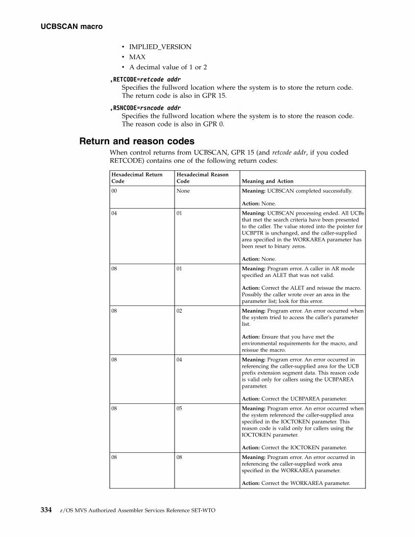
v IMPLIED_VERSIONv MAXv A decimal value of 1 or 2
,RETCODE=retcode addrSpecifies the fullword location where the system is to store the return code.The return code is also in GPR 15.
,RSNCODE=rsncode addrSpecifies the fullword location where the system is to store the reason code.The reason code is also in GPR 0.
Return and reason codesWhen control returns from UCBSCAN, GPR 15 (and retcode addr, if you codedRETCODE) contains one of the following return codes:
Hexadecimal ReturnCode
Hexadecimal ReasonCode Meaning and Action
00 None Meaning: UCBSCAN completed successfully.
Action: None.
04 01 Meaning: UCBSCAN processing ended. All UCBsthat met the search criteria have been presentedto the caller. The value stored into the pointer forUCBPTR is unchanged, and the caller-suppliedarea specified in the WORKAREA parameter hasbeen reset to binary zeros.
Action: None.
08 01 Meaning: Program error. A caller in AR modespecified an ALET that was not valid.
Action: Correct the ALET and reissue the macro.Possibly the caller wrote over an area in theparameter list; look for this error.
08 02 Meaning: Program error. An error occurred whenthe system tried to access the caller's parameterlist.
Action: Ensure that you have met theenvironmental requirements for the macro, andreissue the macro.
08 04 Meaning: Program error. An error occurred inreferencing the caller-supplied area for the UCBprefix extension segment data. This reason codeis valid only for callers using the UCBPAREAparameter.
Action: Correct the UCBPAREA parameter.
08 05 Meaning: Program error. An error occurred whenthe system referenced the caller-supplied areaspecified in the IOCTOKEN parameter. Thisreason code is valid only for callers using theIOCTOKEN parameter.
Action: Correct the IOCTOKEN parameter.
08 08 Meaning: Program error. An error occurred inreferencing the caller-supplied work areaspecified in the WORKAREA parameter.
Action: Correct the WORKAREA parameter.
UCBSCAN macro
334 z/OS MVS Authorized Assembler Services Reference SET-WTO

Hexadecimal ReturnCode
Hexadecimal ReasonCode Meaning and Action
08 0A Meaning: Program error. An error occurred inreferencing the caller-supplied area for the pinreason text (TEXT). This reason code is valid onlyfor callers using the TEXT parameter.
Action: Correct the TEXT parameter.
08 0D Meaning: The value specified on the SCHSETkeyword is not valid.
Action: Correct the SCHSET value.
0C None Meaning: Environmental error. The I/Oconfiguration has changed, so that the I/Oconfiguration token supplied through theIOCTOKEN parameter is not current. This returncode is valid only for callers using theIOCTOKEN parameter.
Action: Obtain the current I/O configurationtoken by issuing an IOCINFO macro or bysetting the input IOCTOKEN parameter in theUCBINFO macro to zero. Start the scan from thebeginning.
20 None Meaning: System error. An unexpected erroroccurred.
Action: Supply the return code to the appropriateIBM support personnel.
UCBSCAN ADDRESS - List formUse the list form of the UCBSCAN macro together with the execute form forapplications that require reentrant code. The list form of the macro defines an areaof storage that the execute form uses for storing the parameters.
SyntaxThis macro is an alternative list form macro, and requires a different technique forusing the list form as compared to the conventional list form macros. See“Alternative list form macros” on page 13 for further information.
The list form of the ADDRESS function of the UCBSCAN macro is written asfollows:
Syntax Description
name name: Symbol. Begin name in column 1.
� One or more blanks must precede UCBSCAN.
UCBSCAN
� One or more blanks must follow UCBSCAN.
,PLISTVER=IMPLIED_VERSION
UCBSCAN macro
Chapter 27. UCBSCAN — Scan UCBs 335

Syntax Description
,PLISTVER=MAX Default: IMPLIED_VERSION
,PLISTVER=plistver plistver: 1 - 2
MF=(L,list addr) list addr: symbol.
MF=(L,list addr,attr) attr: 1- to 60-character input string.
MF=(L,list addr,0D) Default: 0D
ParametersThe parameters are explained under the standard form of the ADDRESS functionof the UCBSCAN macro with the following exceptions:
MF=(L,list addr)MF=(L,list addr,attr)MF=(L,list addr,0D)
Specifies the list form of the UCBSCAN macro.
The list addr parameter specifies the address of the storage area for theparameter list.
attr is an optional 1- to 60-character input string, which can contain any valuethat is valid on an assembler DS pseudo-op. You can use this parameter toforce boundary alignment of the parameter list. If you do not code attr, thesystem provides a value of 0D, which forces the parameter list to adoubleword boundary.
UCBSCAN ADDRESS - Execute formUse the execute form of the UCBSCAN macro together with the list form forapplications that require reentrant code. The execute form of the macro stores theparameters into the storage area defined by the list form.
SyntaxThe execute form of the ADDRESS function of the UCBSCAN macro is written asfollows:
Syntax Description
name name: Symbol. Begin name in column 1.
� One or more blanks must precede UCBSCAN.
UCBSCAN
� One or more blanks must follow UCBSCAN.
ADDRESS Note: COPY is the default.
UCBSCAN macro
336 z/OS MVS Authorized Assembler Services Reference SET-WTO

Syntax Description
,WORKAREA=workarea addr workarea addr: RX-type address or register (2) - (12).
,UCBPTR=ucbptr addr ucbptr addr: RS-type address or register (2) - (12).
,UCBCXPTR=ucbcxptr addr ucbcxptr: RX-type address or register (2) - (12).
,UCBPXPTR=ucbpxptr addr ucbpxptr: RX-type address or register (2) - (12).
,LOC=BELOW Default: BELOW
,LOC=ANY
,PIN Note: TEXT and PTOKEN are required with PIN
,NOPIN
,TEXT=text addr: text addr: RX-type address
Note: Required with PIN, not valid with NOPIN.
,PTOKEN=ptoken addr: ptoken addr: RS-type address or register (2) - (12).
Note: Required with PIN, not valid with NOPIN.
,UCBPAREA=ucbparea addr ucbparea addr: RX-type address or register (2) - (12).
,UCBPAREA=NONE Default: NONE
,DEVN=devn addr devn addr: RS-type address or register (2) - (12).
,DEVN=0 Default: 0
,SUBCHANNELSET=ID
,SCHSET=xschset xschset RS-type address or register (2) - (12).
,SCHSET=0 Default: 0
,SUBCHANNELSET=ALL
,DYNAMIC=NO Default: NO
,DYNAMIC=YES
,RANGE=3DIGIT Default: 3DIGIT
,RANGE=ALL
,UNBOUND_ALIAS=NO Default: NO
,UNBOUND_ALIAS=YES
,UNBOUND_ALIAS=ONLY
UCBSCAN macro
Chapter 27. UCBSCAN — Scan UCBs 337

Syntax Description
,DEVCLASS=ALL Default: ALL
,DEVCLASS=CHAR
,DEVCLASS=COMM
,DEVCLASS=CTC
,DEVCLASS=DASD
,DEVCLASS=DISP
,DEVCLASS=TAPE
,DEVCLASS=UREC
,DEVCID=devcid addr devcid addr: RS-type address
,IOCTOKEN=ioctoken addr ioctoken addr: RX-type address or register (2) - (12).
,IOCTOKEN=NONE Default: NONE
,LINKAGE=SYSTEM Default: LINKAGE=SYSTEM
,LINKAGE=BRANCH
,PLISTVER=IMPLIED_VERSION
,PLISTVER=MAX Default: IMPLIED_VERSION
,PLISTVER=plistver plistver: 1 - 2
,RETCODE=retcode addr retcode addr: RX-type address or register (2) - (12).
,RSNCODE=rsncode addr rsncode addr: RX-type address or register (2) - (12).
,MF=(E,list addr) list addr: RX-type address or register (2) - (12).
,MF=(E,list addr,COMPLETE) Default: COMPLETE
SPECIAL=NO Default: NO
SPECIAL=YES
SPECIAL=ONLY
ParametersThe parameters are explained under the standard form of the ADDRESS functionof the UCBSCAN macro with the following exceptions:
,MF=(E,list addr),MF=(E,list addr,COMPLETE)
Specifies the execute form of the UCBSCAN macro.
UCBSCAN macro
338 z/OS MVS Authorized Assembler Services Reference SET-WTO

The list addr parameter specifies the address of the storage area for theparameter list. COMPLETE specifies that the system is to check for requiredparameters and supply defaults for optional parameters that were notspecified.
UCBSCAN macro
Chapter 27. UCBSCAN — Scan UCBs 339

UCBSCAN macro
340 z/OS MVS Authorized Assembler Services Reference SET-WTO

Chapter 28. VSMLIST — List virtual storage map
DescriptionThe VSMLIST macro provides information about the allocation of virtual storage.The information is returned in a work area that you specify. The format of thework area is described under “Virtual Storage Management” in z/OS MVSProgramming: Authorized Assembler Services Guide.
The following information can be requested:v The ranges of virtual storage allocated to the SQA, by subpool, and the free
space within those rangesv The ranges of virtual storage allocated to the CSA, by subpool, and the free
space within those rangesv The ranges of CSA space that are unallocatedv The ranges of virtual storage allocated to the LSQA in the current address space,
by subpool, and the free space within those rangesv The ranges of virtual storage allocated to private area subpools, by TCB, and the
free space within those rangesv The ranges of private area that are unallocated.
For detailed information about virtual storage subpools, see “Virtual StorageManagement” in z/OS MVS Programming: Authorized Assembler Services Guide.
EnvironmentThe requirements for the caller are:
Environmental factor RequirementMinimum authorization: For LINKAGE=SYSTEM, problem state and PSW key 8-15.
For LINKAGE=BRANCH, supervisor state and PSW key 0.Dispatchable unit mode: Task or SRB.Cross memory mode: Any PASN, any HASN, any SASN.AMODE: 24- or 31-bit. All addresses must be 31-bit addresses.ASC mode: Primary.Interrupt status: Enabled or disabled for I/O and external interrupts.Locks: v For LINKAGE=SYSTEM, the caller may not hold a lock
higher than the local lock.
v For LINKAGE=BRANCH, see the LINKAGE parameterdescription for locking requirements.
Control parameters: Must be in the primary address space. All input parameters,except for the TCB, can reside above 16 megabytes if thecaller is running in 31-bit addressing mode. The TCB residesbelow 16 megabytes.
Programming requirementsAll addresses are associated with the current address space.
You must set bytes 0-3 of the work area to zero before the first invocation of themacro for a given request.
© Copyright IBM Corp. 1988, 2017 341

RestrictionsNone.
Input register informationThe VSMLIST macro is sensitive to the SYSSTATE macro with the OSRELparameterv If the caller has issued the SYSSTATE macro with the OSREL=ZOSV1R6
parameter (Version 1 Release 6 of z/OS or later) before issuing the VSMLISTmacro, the caller does not have to place any information into any generalpurpose register (GPR) unless using it in register notation for a particularparameter, or using it as a base register.
v Otherwise, the caller must ensure that the following general purpose registercontains the specified information:
RegisterContents
13 The address of an 18-word save area
Output register informationWhen control returns to the caller, the GPRs contain:
RegisterContents
0-1 Used as work registers by the system
2-13 Unchanged
14 Used as a work register by the system
15 Return code
When control returns to the caller, the ARs contain:
RegisterContents
0-1 Used as work registers by the system
2-13 Unchanged
14-15 Used as work registers by the system
Some callers depend on register contents remaining the same before and afterissuing a service. If the system changes the contents of registers on which the callerdepends, the caller must save them before issuing the service, and restore themafter the system returns control.
Performance implicationsNone.
SyntaxThe VSMLIST macro is written as follows:
Syntax Description
name name: Symbol. Begin name in column 1.
VSMLIST macro
342 z/OS MVS Authorized Assembler Services Reference SET-WTO

Syntax Description
� One or more blanks must precede VSMLIST.
VSMLIST
� One or more blanks must follow VSMLIST.
SP=SQA
SP=CSA
SP=LSQA
SP=PVT
SP=sp list addr sp list addr: RX-type address or register (0), (2) - (12)
,WKAREA=(addr,length) addr: RX-type address or register (1) - (12)
length: Symbol, decimal digit, or register (0), (2) - (12).
,TCB=(tcb addr) Default: TCB address in PSATOLD.
,TCB=(tcb addr,ALL) tcb addr: RX-type address or register (0), (2) - (12).
,TCB=(, ALL) Note: The TCB parameter is required only for SRB routines, if SP=PVT orSP=sp list addr and the list contains private area subpools.
,SPACE=ALLOC Default: SPACE=ALLOC
,SPACE=FREE Note: SPACE=UNALLOC can be specified only for SP=CSA or SP=PVT.
,SPACE=UNALLOC
,LOC=24 Default: LOC=31
,LOC=31
,REAL31 Default: REAL31
,REAL64
,REALPGFMSZ
,LINKAGE=SYSTEM Default: LINKAGE=SYSTEM
,LINKAGE=BRANCH
,PVTSP=ALL Default: PVTSP=ALL
,PVTSP=OWNED
VSMLIST macro
Chapter 28. VSMLIST — List virtual storage map 343

ParametersThe parameters are explained as follows:
SP=SQASP=CSASP=LSQASP=PVTSP=sp list addr
Specifies the storage areas for which information is requested. The followingsubpools are listed for the specified storage areas:v SQA: 226, 239, 245, 247, 248v CSA: 227, 228, 231, 241v LSQA: 205, 215, 225, 255v PVT: 0-127, 129–132, 229, 230, 236, 237, 244, 249, 251, 252
GETMAIN/FREEMAIN/STORAGE processing translates the original subpoolnumbers that were specified on the GETMAIN, FREEMAIN, or STORAGEmacros to different subpool numbers as shown below:
Original Subpool Number Translated Subpool Number203-205 205213-215 215223-225 225233-235, 253-255 2550, 240, 250 0
VSMLIST reports the translated subpool numbers, not the original subpoolnumbers. In addition, VSMLIST does not report incorrect subpool numbers(subpool numbers greater than 255) or undefined subpool numbers.
If SP=sp list addr is specified, the user must supply the address of a subpoollist. The first halfword of the list contains the number of entries in the list.Each of the following halfwords in the list contains a subpool number. If avalid subpool number appears more than once in the subpool list, it isreported only once.
,WKAREA=(addr,length)Indicates the address and length of a user-supplied work area. The system usesthis work area to hold the parameter list, control information, and data that isto be returned to the caller. The work area should begin on a word boundaryand be a minimum of 4K bytes in length.
You must set bytes 0-3 of this work area to zero before the first invocation ofVSMLIST for a specific request. See “Virtual Storage Management” in z/OSMVS Programming: Authorized Assembler Services Guide for a description of thework area.
,TCB=(tcb addr),TCB=(tcb addr,ALL),TCB=(,ALL)
Specifies the TCB associated with the virtual storage allocated to the privatearea subpools. The TCB must be located in the currently addressable addressspace. If ALL is specified, the storage associated with the TCB and all of itssubtasks is reported.
Note:
VSMLIST macro
344 z/OS MVS Authorized Assembler Services Reference SET-WTO

1. If ALL is specified and the TCB is high in the task structure (for example,the TCB for RCT), more than one region could be listed. The regions in theprivate area are the RCT region, the V=V region, and the V=R region (forV=R jobs).
2. The TCB resides in storage below 16 megabytes.
,SPACE=ALLOC,SPACE=FREE,SPACE=UNALLOC
Specifies whether allocated, allocated and free, or unallocated storage is to bereported.
ALLOC indicates that the virtual addresses and lengths of blocks of storageallocated to the specific area are to be listed.
FREE indicates that in addition to the information supplied by ALLOC, thevirtual addresses and lengths of free space within the allocated blocks are to belisted.
UNALLOC indicates that the virtual addresses and lengths of unallocatedblocks of storage are to be listed. Both TCB and REAL are ignored whenUNALLOC is specified.
Note: An allocated block of storage is a block that is a multiple of 4K in sizeand contains some storage that has been allocated via a GETMAIN orSTORAGE macro. The free storage is the storage within an allocated block thathas not been allocated via a GETMAIN or STORAGE macro. An unallocatedblock of storage is a block that is a multiple of 4K in size and contains noallocated storage.
,LOC=24,LOC=31
Indicates whether information should be returned about virtual storage areasresiding above and below 16 megabytes or only those residing below 16megabytes. If LOC=31 is specified, information is returned for all storage areasbelow 2 gigabytes. If LOC=24 is specified, information is returned only forstorage areas below 16 megabytes.
Note: Specifying LOC=BELOW is the same as specifying LOC=24. SpecifyingLOC=ANY is the same as specifying LOC=31. The old values are stillsupported, but IBM recommends using the newer values instead.
,REAL31,REAL64,REALPGFMSZ
Indicates that the high order bit and the 2 lower order bits of the address fieldof the allocated block descriptor should be set to show the value specified onthe LOC parameter of the GETMAIN, STORAGE, or CPOOL macro invocationused to obtain that storage area. If the storage block was allocated using anyLOC specification of GETMAIN or STORAGE, except for LOC=(*,24), one ormore of these indicators are turned on. If the storage block was allocated usingthe LOC=(*,24) specification of GETMAIN or STORAGE, the indicators areturned off.
Note: The asterisk character (*) indicates that any of the allowable values forthe first suboperand of the LOC keyword.
REAL31If the storage block is backed in real 31-bit or 64-bit storage, the high
VSMLIST macro
Chapter 28. VSMLIST — List virtual storage map 345

bit indicator is on (one). If the storage block is backed in real 24-bitstorage, the high bit indicator is off (zero). The low bit and secondlowest bit indicators are always off.
REAL64If the storage block is backed in real 64-bit storage, the low bitindicator is on (one) and the high bit indicator is off (zero). If thestorage block is backed in real 31-bit storage, the high bit indicator ison (one) and the low bit indicator is off (zero). If the storage block isbacked in real 24-bit storage, the high bit indicators are off (zero). The2nd lowest bit indicator is always off (zero).
REALPGFMSZSpecifies the following indicators:v If the storage block was obtained with the PAGEFRAMESIZE1MB
parameter, the second lowest bit indicator is on (one), the low bitindicator is on (one) and the high bit indicator is off (zero).
v If the storage block is backed in real 64-bit storage but was notobtained with the PAGEFRAMESIZE1MB parameter, the low bitindicator is on (one), the 2nd lowest bit indicator is off (zero) andthe high bit indicator is off (zero).
v If the storage block is backed in real 31-bit storage, the high bitindicator is on (one), the low bit indicator is off (zero) and the 2ndlowest bit indicator is off (zero).
v If the storage block is backed in real 24-bit storage, the high bitindicator, the low bit indicator and the second lowest bit indicatorsare off (zero).
Note:
1. If REAL31, REAL64 and REALPGFMSZ are not specified, then none ofthese indicators are turned on.
2. The REAL31 parameter provides the same function as the deprecated REALparameter, which is still supported by VSMLIST.
,LINKAGE=SYSTEM,LINKAGE=BRANCH
Indicates whether the VSMLIST routine uses a PC instruction(LINKAGE=SYSTEM) or branch entry (LINKAGE=BRANCH) for linkage andwhether the VSMLIST routine provides serialization and recovery.
If LINKAGE=SYSTEM is specified, the VSMLIST routine provides linkageusing a PC instruction and also provides recovery and serialization.
The caller's secondary ASID is preserved when a PC is issued.
Note: Serialization is not provided across calls to VSMLIST.
If LINKAGE=BRANCH is specified, the VSMLIST routine uses branch entryfor linkage and does not provide recovery or serialization. Before issuingVSMLIST, provide serialization as follows:v For LSQA or PVT requests, obtain the LOCAL lock.v For SQA or CSA requests, issue the SETLOCK macro right before and right
after the VSMLIST request, as follows:SETLOCK OBTAIN,TYPE=VSMFIX,MODE=UNCONDVSMLIST requestSETLOCK RELEASE,TYPE=VSMFIX
VSMLIST macro
346 z/OS MVS Authorized Assembler Services Reference SET-WTO

If your program is covered by a functional recovery routine (FRR) and theFRR receives control after SETLOCK OBTAIN has been issued and beforeSETLOCK RELEASE has been issued, your FRR must either issue SETLOCKRELEASE,TYPE=VSMFIX or must issue the SETLOCK and SETRP macros asfollows:
SETLOCK TEST,TYPE=VSMFIX,BRANCH=(NOTHELD,NOVSMFIX)SETRP FRELOCK=VSMFIX
NOVSMFIX DS 0H
Note:
1. Your program will be disabled for I/O and external interrupts from thetime the SETLOCK OBTAIN completes until the SETLOCK RELEASEcompletes. See the descriptions of the SETLOCK and SETRP macros foradditional usage information.
2. Your program and your FRR must not issue any of the following macrosbefore issuing SETLOCK RELEASE,TYPE=VSMFIX:– GETMAIN– FREEMAIN– STORAGE
,PVTSP=ALL,PVTSP=OWNED
Indicates for each task, which subpool information will be returned.
ALL indicates that information is returned for subpools which are owned orshared by the task.
OWNED indicates that information is returned only for the subpools which areowned by the task.
ABEND codesThe VSMLIST macro might issue abend code X'C78'. For detailed abend codeinformation, see z/OS MVS System Codes.
Return and reason codesWhen the VSMLIST macro returns control to your program, GPR 15 contains oneof the following hexadecimal return codes:
Table 42. Return Codes for the VSMLIST Macro
Return Code Meaning and Action
0 Meaning: Successful completion.
Action: None.
4 Meaning: Partially successful completion. More information remains to bereturned in the work area.
Action: Reissue the macro to obtain additional information until a returncode of 0 is returned in register 15. Do not change the value of bytes 0-3 ofthe work area before reissuing the macro.
VSMLIST macro
Chapter 28. VSMLIST — List virtual storage map 347

Table 42. Return Codes for the VSMLIST Macro (continued)
Return Code Meaning and Action
8 Meaning: System error. The system encountered an error while scanningvirtual storage management data areas. The information in the data area isvalid, but incomplete. This return code is obtained only by users whospecify LINKAGE=SYSTEM.
Action: Notify system support personnel that there might be an error invirtual storage management's control structure. If there is a problem withVSM's control structure, the entire system will be adversely affected andyou might need to wait until the problem is identified and resolved bysupport personnel. Support personnel should take a dump of the virtualstorage management control structure to help identify the cause of theproblem. If the problem appears to involve common storage, the contentsof common storage should be dumped to view the VSM control structure.If the problem appears to involve private storage, private storage should bedumped.
C Meaning: Program error. The system detected one of the following errors:
v The work area was too small.
v An incorrect parameter was specified.
v Incorrect control information was in the work area.
This return code is obtained only by users who specifyLINKAGE=BRANCH. Users who specify LINKAGE=SYSTEM receive aX'C78' abend for these errors.
Action: Ensure that the work area is at least 4096 bytes long. Verify that thework area is correctly defined and initialized and that parameters arespecified properly. Verify that your program has not inadvertently modifiedthe VSMLIST work area.
Example 1List the ranges of the allocated and free storage in the SQA. Specify the address ofthe VSM work area in register 2 and the length of the work area in register 3.VSMLIST SP=SQA,SPACE=FREE,WKAREA=((2),(3))
Example 2List the ranges of the allocated storage in the CSA. Specify the address of the workarea in register 2 and the length of the work area in register 3. Provide branchentry linkage.VSMLIST SP=CSA,SPACE=ALLOC,WKAREA=((2),(3)),LINKAGE=BRANCH
Example 3List the ranges of unallocated storage in the private area. The variable X containsthe address of the work area, which has a length of 4096 bytes.VSMLIST SP=PVT,SPACE=UNALLOC,WKAREA=(X,4096)
Example 4List the ranges of allocated storage, below 16 megabytes, in each of the subpoolsspecified in the subpool list at location Y. The variable X contains the address ofthe work area, which has a length of 4096 bytes.VSMLIST SP=Y,SPACE=ALLOC,WKAREA=(X,4096),LOC=BELOW
VSMLIST macro
348 z/OS MVS Authorized Assembler Services Reference SET-WTO

Chapter 29. VSMLOC — Verify virtual storage allocation
DescriptionThe VSMLOC macro verifies that a given storage area has been allocated using theGETMAIN or STORAGE macros.
EnvironmentThe requirements for the caller are:
Environmental factor RequirementMinimum authorization: For LINKAGE=SYSTEM, problem state and PSW key 8-15.
For LINKAGE=BRANCH, supervisor state and PSW key 0.Dispatchable unit mode: Task or SRB.Cross memory mode: Any PASN, any HASN, any SASN.AMODE: 24- or 31-bit. All addresses passed to VSMLOC must be
31-bit addresses.ASC mode: Primary.Interrupt status: For LINKAGE=SYSTEM, enabled or disabled for I/O and
external interrupts. For LINKAGE=BRANCH, interruptstatus depends on the area of storage for which informationis requested. See the LINKAGE=BRANCH parameter forcomplete information.
Locks: v For LINKAGE=SYSTEM with LSQA, PVT, or CPOOLLCLspecified, you may hold only the local lock.
v For LINKAGE=BRANCH, see the LINKAGE=BRANCHparameter for locking requirements.
Control parameters: Must be in the primary address space
Programming requirementsv All addresses are associated with the current address space.v The VSMLOC service does not provide serialization or recovery for callers
specifying LINKAGE=BRANCH. Callers must provide serialization and recoveryas described under the LINKAGE parameter description.
v The VSMLOC service provides serialization and recovery for callers specifyingLINKAGE=SYSTEM.
RestrictionsNone.
Input register information for LINKAGE=SYSTEMThe VSMLOC macro is sensitive to the SYSSTATE macro with theOSREL=ZOSV1R6 parameterv If the caller has issued the SYSSTATE macro with the OSREL=ZOSV1R6
parameter (Version 1 Release 6 of z/OS or later) before issuing the VSMLOCmacro, the caller does not have to place any information into any generalpurpose register (GPR) unless using it in register notation for a particularparameter, or using it as a base register.
v Otherwise, the caller must ensure that the following general purpose registercontains the specified information:
© Copyright IBM Corp. 1988, 2017 349

RegisterContents
13 The address of an 18-word save area
Output register information for LINKAGE=SYSTEMWhen control returns to the caller, the GPRs contain:
RegisterContents
0 If GPR15 contains a value of zero, byte 3 contains the number of thesubpool from which the specified storage area was obtained. Bytes 0-2 donot contain any relevant information.
If GPR15 contains a nonzero value, contains zero.
For detailed information about virtual storage subpools, see “VirtualStorage Management” in z/OS MVS Programming: Authorized AssemblerServices Guide.
1 Used as a work register by the system.
2-13 Unchanged.
14 Used as a work register by the system.
15 Return code.
When control returns to the caller, the access registers (ARs) contain:
RegisterContents
0-1 Used as work registers by the system
2-13 Unchanged
14-15 Used as work registers by the system
Input register information for LINKAGE=BRANCHThe caller must ensure that the following general purpose register (GPR) containsthe specified information:
RegisterContents
13 The address of an 18-word save area
Output register information for LINKAGE=BRANCHWhen control returns to the caller, the GPRs contain:
RegisterContents
0 If GPR15 contains a value of 0, byte 3 contains the number of the subpoolfrom which the specified storage area was obtained. Bytes 0-2 do notcontain any relevant information.
If GPR15 contains a nonzero value, contains zero.
For detailed information about virtual storage subpools, see “VirtualStorage Management” in z/OS MVS Programming: Authorized AssemblerServices Guide.
VSMLOC macro
350 z/OS MVS Authorized Assembler Services Reference SET-WTO

1-2 Used as work registers by the system
3-13 Unchanged.
14 Used as a work register by the system.
15 Return code.
When control returns to the caller, the ARs contain:
RegisterContents
0-1 Used as work registers by the system
2-13 Unchanged
14-15 Used as work registers by the system
Some callers depend on register contents remaining the same before and afterissuing a service. If the system changes the contents of registers on which the callerdepends, the caller must save them before issuing the service, and restore themafter the system returns control.
Performance implicationsNone.
SyntaxThe VSMLOC macro is written as follows:
Syntax Description
name name: Symbol. Begin name in column 1.
� One or more blanks must precede VSMLOC.
VSMLOC
� One or more blanks must follow VSMLOC.
SQA
CSA
LSQA
PVT
CPOOLFIX
CPOOLPAG
CPOOLLCL
,AREA=(addr,length) addr: RX-type address or register (0) - (12).
length: Symbol, decimal digit or register (0), (2) - (12). Use only with SQA,CSA, LSQA, and PVT.
VSMLOC macro
Chapter 29. VSMLOC — Verify virtual storage allocation 351

Syntax Description
,AREA=(addr) addr: RX-type address or register (0) - (12). Use only with CPOOLFIX,CPOOLPAG, and CPOOLLCL.
,TCB=addr
addr: RX-type address or register (0) - (12). Can only be specified with PVT.
,LINKAGE=SYSTEM Default: LINKAGE=SYSTEM
,LINKAGE=BRANCH
ParametersThe parameters are explained as follows:
SQA CSA LSQA PVT CPOOLFIX CPOOLPAG CPOOLLCL
Used to verify that storage has been allocated.
SQA, CSA, LSQA, and PVT are used to verify that storage for SQA, CSA,LSQA, or PVT (private area storage) has been allocated in the current addressspace.
CPOOLFIX is used to verify that storage for a global fixed cell pool has beenallocated. Users who obtain their storage from subpool 226, 227, 228, 239, or245 should specify this keyword.
CPOOLPAG is used to verify that storage for a global pageable cell pool hasbeen allocated. Users who obtain storage from subpool 231, 241, 247, or 248should specify this keyword.
CPOOLLCL is used to verify that storage for a local cell pool has beenallocated. Users who obtain storage from subpool 0-127, 129-132, 203-205,213-215, 223-225, 229, 230, 233-237, 240, 249, or 250-255 should specify thiskeyword.
,AREA=(addr,length)Indicates the start of the virtual storage area (addr) and the length of the virtualstorage area (length) to be verified.
,AREA=(addr)Indicates the start of the virtual storage area (addr) to be verified.
,TCB=addrIndicates that VSMLOC is to place the address of the TCB associated with theverified storage in the register or storage area specified by the TCB parameter.If the return code from VSMLOC is not zero, the register or storage areaspecified by the TCB parameter is set to zero. The TCB parameter can bespecified only with PVT.
,LINKAGE=SYSTEM
VSMLOC macro
352 z/OS MVS Authorized Assembler Services Reference SET-WTO

,LINKAGE=BRANCHIndicates the type of linkage that VSMLOC is to use.
If LINKAGE=SYSTEM is specified, the VSMLOC routine uses a basic PCinstruction for linkage.
The caller's secondary ASID is preserved when a basic PC is issued.
If LINKAGE=BRANCH is specified, the VSMLOC routine uses branch entrylinkage. Before issuing VSMLOC, provide serialization as follows:v For LSQA, CPOOLLCL, and PVT requests, obtain the LOCAL lock.v For CSA, SQA, and CPOOLFIX requests, issue the SETLOCK macro right
before and right after the VSMLOC request, as follows:SETLOCK OBTAIN,TYPE=VSMFIX,MODE=UNCONDVSMLOC requestSETLOCK RELEASE,TYPE=VSMFIX
If your program is covered by a functional recovery routine (FRR) and theFRR receives control after SETLOCK OBTAIN has been issued and beforeSETLOCK RELEASE has been issued, your FRR must either issue SETLOCKRELEASE,TYPE=VSMFIX or must issue the SETLOCK and SETRP macros asfollows:
SETLOCK TEST,TYPE=VSMFIX,BRANCH=(NOTHELD,NOVSMFIX)SETRP FRELOCK=VSMFIX
NOVSMFIX DS 0H
Note:
1. Your program will be disabled for I/O and external interrupts from thetime the SETLOCK OBTAIN completes until the SETLOCK RELEASEcompletes. See the descriptions of the SETLOCK and SETRP macros foradditional usage information.
2. Your program and your FRR must not issue any of the following macrosbefore issuing SETLOCK RELEASE,TYPE=VSMFIX:– GETMAIN– FREEMAIN– STORAGE
v For CPOOLPAG requests, issue the SETLOCK macro right before and rightafter the VSMLOC request, as follows:SETLOCK OBTAIN,TYPE=VSMPAG,MODE=UNCONDVSMLOC requestSETLOCK RELEASE,TYPE=VSMPAG
If your program is covered by a functional recovery routine (FRR) and theFRR receives control after SETLOCK OBTAIN has been issued and beforeSETLOCK RELEASE has been issued, your FRR must either issue SETLOCKRELEASE,TYPE=VSMPAG or must issue SETLOCK and SETRP macros asfollows:
SETLOCK TEST,TYPE=VSMPAG,BRANCH=(NOTHELD,NOVSMPAG)SETRP FRELOCK=VSMPAG
NOVSMPAG DS 0H
Note:
1. Your program will be disabled for I/O and external interrupts from thetime the SETLOCK OBTAIN completes until the SETLOCK RELEASEcompletes. See the descriptions of the SETLOCK and SETRP macros foradditional usage information.
VSMLOC macro
Chapter 29. VSMLOC — Verify virtual storage allocation 353

2. Your program and your FRR must not issue any of the following macrosbefore issuing SETLOCK RELEASE,TYPE=VSMPAG:– GETMAIN– FREEMAIN– STORAGE
ABEND codesThe VSMLOC macro might issue abend code X'C78'. For detailed abend codeinformation, see z/OS MVS System Codes.
Return and reason codesWhen the VSMLOC macro returns control to your program, GPR 15 contains oneof the following hexadecimal return codes:
Table 43. Return Codes for the VSMLOC Macro
Return Code Meaning and Action
0 Meaning: Successful completion. The specified virtual storage area isallocated.
Action: None.
4 Meaning: Possible program error. The specified virtual storage area is:
v Not allocated.
v Overlaps free space.
v Overlaps other subpools.
Action: This return code is not a program error if you have issuedVSMLOC to determine whether the storage at the specified address iscurrently allocated and the system indicates that it is not. This return codesignifies a program error if you expected the specified storage area to beallocated and the system reports one of the conditions listed above. If thisis an error, you need to determine why the storage area is in the indicatedstate. Possible reasons include:
v The storage area address or length is not valid.
v The storage has been freed by another program.
v The storage was in a subpool that is automatically freed by the systemand the system has freed the storage.
8 Meaning: System error. The system encountered an error while scanningvirtual storage management data areas. This return code is obtained onlyby users who specify LINKAGE=SYSTEM.
Action: Notify system support personnel that there might be an error invirtual storage management's control structure. If there is a problem withVSM's control structure, the entire system will be adversely affected andyou might have to wait until the problem is identified and resolved. Systemsupport personnel should request a dump of the virtual storagemanagement control structure and contact IBM support. If the problemappears to involve common storage, the contents of common storageshould be dumped to view the VSM control structure. If the problemappears to involve private storage, private storage should be dumped.
C Meaning: Program error. You have specified a parameter incorrectly. Thisreturn code is obtained only by users who specify LINKAGE=BRANCH.Users who specify LINKAGE=SYSTEM receive a X'C78' abend for thiserror.
Action: Ensure that the virtual storage area you have specified does notexceed 2 gigabytes. Verify that you have coded the parameters as required.
10 Meaning: System error. Internal system error.
Action: Record the return code and notify IBM support personnel.
VSMLOC macro
354 z/OS MVS Authorized Assembler Services Reference SET-WTO

Example 1Verify that the virtual storage, starting at the address given in register 2 andhaving a length specified in register 3, has been allocated in the SQA.VSMLOC SQA,AREA=((2),(3))
Example 2Verify that the 8-bytes of virtual storage starting at X have been allocated in theCSA. Use a PC instruction for linkage and let VSMLOC provide recovery andserialization.VSMLOC CSA,AREA=(X,8),LINKAGE=SYSTEM
Example 3Verify that the 8-bytes of virtual storage starting at the address specified in register2 have been allocated in the LSQA. Use branch entry for linkage.VSMLOC LSQA,AREA=((2),8),LINKAGE=BRANCH
Example 4Verify that the virtual storage, starting at X and having a length specified inregister 3, has been allocated in private area storage. Use branch entry for linkage.VSMLOC PVT,AREA=(X,(3)),LINKAGE=BRANCH
Example 5Verify that the 100 bytes of virtual storage starting at the address specified inregister 1 have been allocated in private area storage. The address of the TCBassociated with the storage verified is returned in register 4.VSMLOC PVT,AREA=((1),100),TCB=(4),LINKAGE=BRANCH
VSMLOC macro
Chapter 29. VSMLOC — Verify virtual storage allocation 355

VSMLOC macro
356 z/OS MVS Authorized Assembler Services Reference SET-WTO

Chapter 30. VSMREGN — Obtain private area region size
DescriptionThe VSMREGN macro provides the virtual starting address and sizes of the privatearea user regions associated with a given TCB in the current address space. Formore information about the user region, see z/OS MVS Initialization and TuningGuide.
EnvironmentThe requirements for the caller are:
Environmental factor RequirementMinimum authorization: Problem state and PSW key 8-15.Dispatchable unit mode: Task or SRB.Cross memory mode: Any PASN, any HASN, any SASN.AMODE: 24- or 31-bit.
All addresses passed to VSMREGN must be 31-bitaddresses.
ASC mode: Primary.Interrupt status: Enabled or disabled for I/O and external interrupts.Locks: v If obtaining user region information for the currently
active task by specifying its TCB address or by taking thedefault value for the TCB keyword, the caller is notrequired to hold any locks.
v Otherwise, the caller must hold the local lock of thecurrently addressable address space.
Control parameters: Must be in the primary address space. All input parametersexcept for the TCB address can reside above 16 megabytes ifthe caller is running in 31-bit addressing mode. The TCBresides below 16 megabytes.
Programming requirementsNone.
RestrictionsNone.
Input register informationBefore issuing the VSMREGN macro, the caller must ensure that the followinggeneral purpose registers (GPRs) contain the specified information:
RegisterContents
13 Address of a standard 72-byte save area
Output register informationWhen control returns to the caller, the GPRs contain:
© Copyright IBM Corp. 1988, 2017 357

RegisterContents
0-1 Used as work registers by the system
2-13 Unchanged
14 Used as a work register by the system
15 Return code
When control returns to the caller, the ARs contain:
RegisterContents
0-1 Used as work registers by the system
2-13 Unchanged
14-15 Used as work registers by the system
Some callers depend on register contents remaining the same before and afterissuing a service. If the system changes the contents of registers on which the callerdepends, the caller must save them before issuing the service, and restore themafter the system returns control.
Performance implicationsNone.
SyntaxThe VSMREGN macro is written as follows:
Syntax Description
name name: Symbol. Begin name in column 1.
� One or more blanks must precede VSMREGN.
VSMREGN
� One or more blanks must follow VSMREGN.
WKAREA=addr addr: RX-type address or register (0) - (12).
,TCB=tcb addr tcb addr: RX-type address or register (0), (2) - (12).
Default: (except for SRB routines) TCB address in PSATOLD.
ParametersThe parameters are explained as follows:
VSMREGN macro
358 z/OS MVS Authorized Assembler Services Reference SET-WTO

WKAREA=addrIndicates the virtual address of a 16-byte work area, which is used byVSMREGN to return the requested information. The format of the work areais:
Bytes Meaning
0-3 Virtual address of the region below 16 megabytes
4-7 Length of the region below 16 megabytes
8-11 Virtual address of the region above 16 megabytes
12-15 Length of the region above 16 megabytes
,TCB=tcb addrIndicates the virtual address of the TCB to be used to identify the region (theregion control task (RCT) region, the V=V region, or the V=R region). SRBroutines and routines whose currently addressable address space is not thehome address space must specify the TCB operand. They cannot use thedefault value.
ABEND codesNone.
Return and reason codesWhen control returns from VSMREGN, GPR 15 always contains a return code ofzero, indicating successful completion.
Example 1Find the virtual address and length of the private area of the TCB whose addressis in PSATOLD. Return the information in the work area whose address is given inregister 2.VSMREGN WKAREA=(2)
Example 2Find the virtual address and length of the private area of the TCB specified inregister 3. Return this information in the work area whose address is given inregister 2.VSMREGN WKAREA=(2),TCB=(3)
Example 3Find the virtual address and length of the private area of the TCB whose addressis X. Return this information in the work area whose address is given in register 2.VSMREGN WKAREA=(2),TCB=X
Example 4Find the virtual address and length of the private area of the TCB whose addressis given in register 3. Return this information in the work area whose address is X.VSMREGN WKAREA=X,TCB=(3)
VSMREGN macro
Chapter 30. VSMREGN — Obtain private area region size 359

VSMREGN macro
360 z/OS MVS Authorized Assembler Services Reference SET-WTO

Chapter 31. WAIT — Wait for one or more events
DescriptionThe WAIT macro is used to tell the system that performance of the active taskcannot continue until one or more specific events, each represented by a differentevent control block (ECB), have occurred. Bit 0 and bit 1 of each ECB must be setto zero before it is used.
The system takes the following action:v For each event that has already occurred (each ECB is already posted), the count
of the number of events is decreased by one.v If the number of events is zero by the time the last event control block is
checked, control is returned to the instruction following the WAIT macro.v If the number of events is not zero by the time the last ECB is checked, control
is not returned to the issuing program until sufficient ECBs are posted to bringthe number to zero. Control is then returned to the instruction following theWAIT macro.
See z/OS MVS Programming: Authorized Assembler Services Guide for information onhow to use the WAIT macro to serialize resources.
EnvironmentThe requirements for callers of WAIT are:
Environmental factor RequirementMinimum authorization: Supervisor state or problem state, with any PSW keyDispatchable unit mode: TaskCross memory mode: One of the following:
v For LINKAGE=SVC: PASN=HASN=SASN
v For LINKAGE=SYSTEM: PASN=HASN=SASN orPASN¬=HASN¬=SASN
AMODE: 24- or 31- or 64-bitRMODE: Includes 64-bitASC mode: PrimaryInterrupt status: Enabled for I/O and external interruptionsLocks: v For LINKAGE=SYSTEM: No locks held
v For LINKAGE=SVC: No locks held, and no enabledunlocked task (EUT) functional recovery routines (FRR)established
Control parameters: ECB and ECBLIST must be in the home address space.
Programming requirementsNone.
RestrictionsWhen using LINKAGE=SVC (the default), the caller cannot have an EUT FRRestablished.
© Copyright IBM Corp. 1988, 2017 361
|
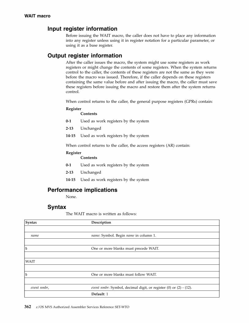
Input register informationBefore issuing the WAIT macro, the caller does not have to place any informationinto any register unless using it in register notation for a particular parameter, orusing it as a base register.
Output register informationAfter the caller issues the macro, the system might use some registers as workregisters or might change the contents of some registers. When the system returnscontrol to the caller, the contents of these registers are not the same as they werebefore the macro was issued. Therefore, if the caller depends on these registerscontaining the same value before and after issuing the macro, the caller must savethese registers before issuing the macro and restore them after the system returnscontrol.
When control returns to the caller, the general purpose registers (GPRs) contain:
RegisterContents
0-1 Used as work registers by the system
2-13 Unchanged
14-15 Used as work registers by the system
When control returns to the caller, the access registers (AR) contain:
RegisterContents
0-1 Used as work registers by the system
2-13 Unchanged
14-15 Used as work registers by the system
Performance implicationsNone.
SyntaxThe WAIT macro is written as follows:
Syntax Description
name name: Symbol. Begin name in column 1.
� One or more blanks must precede WAIT.
WAIT
� One or more blanks must follow WAIT.
event nmbr, event nmbr: Symbol, decimal digit, or register (0) or (2) - (12).
Default: 1
WAIT macro
362 z/OS MVS Authorized Assembler Services Reference SET-WTO

Syntax Description
Value range: 0-255
ECB=ecb addr ecb addr: RX-type address, or register (1) or (2) - (12).
ECBLIST=ecb list addr ecb list addr: RX-type address, or register (1) or (2) - (12).
,LONG=NO Default: LONG=NO
,LONG=YES
,LINKAGE=SVC Default: LINKAGE=SVC
,LINKAGE=SYSTEM
,EUT=NOSAVE Default: EUT=NOSAVE
,EUT=SAVE
,RELATED=value value: Any valid macro keyword specification.
ParametersThe parameters are explained as follows:
event nmbr,Specifies the number of events waiting to occur.
ECB=ecb addrECBLIST=ecb list addr
Specifies the address of an ECB on a fullword boundary or the address of avirtual storage area containing one or more consecutive fullwords on afullword boundary. Each fullword contains the address of an ECB; the highorder bit in the last fullword must be set to one to indicate the end of the list.
The ECB parameter is valid only if the number of events is specified as one oris omitted. The number of ECBs in the list specified by the ECBLIST form mustbe equal to or greater than the specified number of events.
If you specify ECBLIST, ecb list addr and all ECBs on the list must be in thehome address space.
,LONG=NO,LONG=YES
Specifies whether the task is entering a long wait (YES) or a regular wait (NO).
,LINKAGE=SVC,LINKAGE=SYSTEM
Specifies whether the caller is in cross memory mode (LINKAGE=SYSTEM) ornot (LINKAGE=SVC).
When the caller is not in cross memory mode (the primary, secondary, andhome address spaces are the same), use LINKAGE=SVC. With this parameter,linkage is through an SVC instruction.
WAIT macro
Chapter 31. WAIT — Wait for one or more events 363
When the caller is in cross memory mode (the primary, secondary, and homeaddress spaces are not the same), use LINKAGE=SYSTEM. With thisparameter, linkage is through a PC instruction. Note that the ECB must be inthe home address space.
,EUT=NOSAVE,EUT=SAVE
Specifies whether enabled unlocked task (EUT) FRRs, if present, should bepreserved around the WAIT processing. Specify this keyword only if youspecify LINKAGE=SYSTEM.
,RELATED=valueSpecifies information used to self-document macros by “relating” functions orservices to corresponding functions or services. The format and contents of theinformation specified are at the discretion of the user, and may be any validcoding values.
The RELATED parameter is available on macros that provide opposite services(for example, ATTACH/DETACH, GETMAIN/FREEMAIN, andLOAD/DELETE), and on macros that relate to previous occurrences of thesame macros (for example, CHAP and ESTAE).
The RELATED parameter may be used, for example, as follows:WAIT1 WAIT 1,ECB=ECB,RELATED=(RESUME1,
’WAIT FOR EVENT’)...
RESUME1 POST ECB,0,RELATED=(WAIT1,’RESUME WAITER’)
Note: Each of these macros will fit on one line when coded, so there is noneed for a continuation indicator.
CAUTION:A job step with all of its tasks in a WAIT condition is terminated uponexpiration of the time limits that apply to it.
ExampleYou have previously initiated one or more activities to be completedasynchronously to your processing. As each activity was initiated, you set up anECB in which bits 0 and 1 were set to zero. You now wish to suspend your taskvia the WAIT macro until a specified number of these activities have beencompleted.
Completion of each activity must be made known to the system via the POSTmacro. POST causes an addressed ECB to be marked complete. If completion ofthe event satisfies the requirements of an outstanding WAIT, the waiting task ismarked ready and will be executed when its priority allows.
ABEND codesThe caller of WAIT might encounter one of the following abend codes:v 101v 201v 301v 401
WAIT macro
364 z/OS MVS Authorized Assembler Services Reference SET-WTO

See z/OS MVS System Codes for explanations and responses for these codes.
Return and reason codesNone.
Example 1Wait for one event to occur (with a default count).
WAIT ECB=WAITECB..
WAITECB DC F’0’
Example 2Wait for two events to occur.
WAIT 2,ECBLIST=LISTECBS..
LISTECBS DC A(ECB1)DC A(ECB2)DC X’80’DC AL3(ECB3)
Example 3Enter a long wait for a task.
WAIT 1,ECBLIST=LISTECBS,LONG=YES...
LISTECBS DC A(ECB1)DC A(ECB2)DC X’80’DC AL3(ECB3)
WAIT macro
Chapter 31. WAIT — Wait for one or more events 365

WAIT macro
366 z/OS MVS Authorized Assembler Services Reference SET-WTO
Chapter 32. WTL — Write to log
Description
Note: IBM recommends that you use the WTO macro with theMCSFLAG=HRDCPY parameter instead of WTL, because WTO supplies more datathan WTL.
The WTL macro causes a message to be written to the system log (SYSLOG) or theoperations log (OPERLOG) log stream depending on which one of these logs, orboth, is active. The message can include any character that can be used in a C-type(character) DC statement, and is assembled as a variable-length record.
Note: When a message is recorded in SYSLOG, the exact format of the output ofthe WTL macro varies depending on the job entry subsystem (JES2 or JES3) that isbeing used, the output class that is assigned to the log at system initialization, andwhether DLOG is in effect for JES3. See the z/OS MVS System Messages manuals forinformation on the format of logged messages.
z/OS JES3 Commands also contains information about the format of loggedmessages.
The description of the WTL macro follows. The WTL macro is also described inz/OS MVS Programming: Assembler Services Reference IAR-XCT (with the exception ofthe OPTION parameter).
EnvironmentThe requirements for the caller are:
Environmental factor RequirementMinimum authorization: Problem state and any PSW key. For OPTION,
APF-authorized with PSW key 0-7, or supervisor stateDispatchable unit mode: TaskCross memory mode: PASN=HASN=SASNAMODE: 24- or 31-bitASC mode: PrimaryInterrupt status: Enabled for I/O and external interruptsLocks: No locks heldControl parameters: Must be in the primary address space
Programming requirementsNone.
RestrictionsMessage text cannot exceed 126 characters. If the message text exceeds 126characters, truncation occurs after the 126th character.
© Copyright IBM Corp. 1988, 2017 367

Input register informationBefore issuing the WTL macro, the caller does not have to place any informationinto any register unless using it in register notation for a particular parameter, orusing it as a base register.
Output register informationWhen control returns to the caller, the GPRs contain:
RegisterContents
0 Reason code
1-14 Unchanged
15 Return code
When control returns to the caller, the access registers (ARs) contain:
RegisterContents
0-1 Used as work registers by the system
2-13 Unchanged
14-15 Used as work registers by the system
Some callers depend on register contents remaining the same before and afterissuing a service. If the system changes the contents of registers on which the callerdepends, the caller must save them before issuing the service, and restore themafter the system returns control.
Performance implicationsNone.
SyntaxThe standard form of the WTL macro is written as follows:
Syntax Description
name name: Symbol. Begin name in column 1.
� One or more blanks must precede WTL.
WTL
� One or more blanks must follow WTL.
‘msg’ msg: Up to 126 characters if OPTION=NOPREFIX is specified. Up to 128characters if OPTION=PREFIX is specified.
,OPTION=PREFIX Default: OPTION=NOPREFIX
,OPTION=NOPREFIX
WTL macro
368 z/OS MVS Authorized Assembler Services Reference SET-WTO

Syntax Description
ParametersThe parameters are explained as follows:
‘msg’Specifies the message to be written to the system log and/or the operationslog. The message must be enclosed in apostrophes, which will not appear inthe log. The message can include any character that can be used in a C-type(character) DC statement, and is assembled as a variable-length record. See“Timing and Communication” in z/OS MVS Programming: Assembler ServicesGuide for a list of the printable EBCDIC characters passed to display devices orprinters.
,OPTION=PREFIX,OPTION=NOPREFIX
Specifies whether the WTL text contains a prefix identifying the system logrecord. If PREFIX is specified, the text already contains a prefix. If NOPREFIXis specified or if this parameter is omitted, a two-character prefix will be addedby the system. The OPTION keyword is ignored by any program running inthe JES3 primary address space.
ABEND codesNone.
Return and reason codesWhen the WTL macro returns control to your program, GPR 15 contains ahexadecimal return code and GPR 0 contains a hexadecimal reason code. WTLissues a return code (either 00 or 04), with multiple reason codes for each. Thereturn codes indicate the following:v 00 - WTL wrote the message to the system log, the operations log, or both.v 04 - WTL could not write the message to either the system log or the operations
log.
Table 44. Return and Reason Codes for the WTL Macro
Return Code Reason Code Meaning and Action
00 00 Meaning: WTL processing completed successfully. Thesystem logged the message in SYSLOG, and if OPERLOGwas requested, the system logged the message inOPERLOG.
Action: None.
00 04 Meaning: WTL processing completed successfully. Themessage was logged in the operations log (OPERLOGlogstream). The system log was not active.
Action: If you want the message logged in the system log,start the system log and rerun the program.
WTL macro
Chapter 32. WTL — Write to log 369

Table 44. Return and Reason Codes for the WTL Macro (continued)
Return Code Reason Code Meaning and Action
00 08 Meaning: WTL processing completed, but the message wasonly logged in the operations log because the WTL systemlog buffers are full.
Action: Do one of the following, if you want subsequentmessages logged in the system log:
v Enter a CONTROL M,LOGLIM command to change theallocated number of WTL system log buffersdynamically.
v Change the LOGLIM value specifying the number ofWTL system log buffers on the INIT statement in theCONSOLxx parmlib member. This value will take effectat the next IPL.
00 0C Meaning: WTL processing completed, but the message wasonly logged in the system log because the operations logwas not active.
Action: If you want the message logged in the operationslog, start the operations log and rerun the program. Thiswill also place the message in the system log.
00 10 Meaning: WTL processing completed, but the message wasonly logged in the system log. The message was not loggedin the operations log stream because of a storage problem.
Action: If you want the message logged in the operationslog, retry the request. This will also place the message inthe system log. If the problem persists, contact the IBMSupport Center. Provide the return and reason code.
04 04 Meaning: System error. WTL processing was notsuccessful. Recovery could not be established.
Action: Retry the request. If the problem persists, recordthe return and reason code and supply it to the appropriateIBM support personnel.
04 08 Meaning: Environmental error. The system log and theoperations log are not active.
Action: Start the logs and rerun your program.
04 0C Meaning: Environmental error. The WTL limit has beenreached.
Action: Do one of the following:
1. Retry the request when the shortage is relieved.
2. Issue a CONTROL M,LOGLIM command to change theallocated number of WTL SYSLOG buffers.
3. Change the LOGLIM value on the INIT statement inthe CONSOLxx member of SYS1.PARMLIB. This newvalue will take effect at the next IPL.
Note: If the problem is persistent, you might want toperform step 2 first and step 3 at the next IPL.
04 10 Meaning: System error. An internal error occurred. Thesystem issues message IEE390I.
Action: Contact the IBM Support Center. Provide the returnand reason code.
04 14 Meaning: System error. The system encountered a (VSM)error. The system issues message IEE390I.
Action: Contact the IBM Support Center. Provide the returnand reason code.
WTL macro
370 z/OS MVS Authorized Assembler Services Reference SET-WTO

Table 44. Return and Reason Codes for the WTL Macro (continued)
Return Code Reason Code Meaning and Action
04 18 Meaning: Environmental error. The message was notlogged in either the system log or the operations log,because neither log is active.
Action: Do one of the following:
v If you want to log the message in the operations log,start the operations log with the VARYOPERLOG,HARDCPY command and rerun the program.
v If you want the message logged in the system log, startthe system log (SYSLOG) with the VARYSYSLOG,HARDCPY command and rerun the program.
04 1C Meaning: Environmental error. The message was notlogged in the system log, as requested, because the WTLlimit has been reached. The operation log was not active atthe time, so the message was not logged there either.
Action: To log the message in the system log, do thefollowing:
v Retry the request when the storage shortage has beenrelieved.
v Issue a CONTROL M,LOGLIM command to change theallocated number of WTL SYSLOG buffers.
v Change the LOGLIM value on the INIT statement in theCONSOLxx member of SYS1.PARMLIB. This new valuewill take effect at initialization.
If the problem persists, issue the CONTROL M,LOGLIMcommand first, and change the LOGLIM value inCONSOLxx at your next IPL.
To log the message in the operations log, start theoperations log and rerun the program.
04 20 Meaning: Environment error. The message was not loggedin the operations log, as requested, because of storageproblems. The system log was not active.
Action: To log the message in the operations log, retry therequest. If the problem persists, contact the IBM SupportCenter, providing the return and reason codes.
To log the message in the system log also, start the systemlog and rerun the program.
04 24 Meaning: Environment error. The message was not loggedin the system log because the WTL limit has been reached,and was not logged in the operation log because of storageproblems.
Action: To log the message in the operations log, retry therequest. If the problem persists, contact the IBM SupportCenter, providing the return and reason codes.
To log the message in the system log also, start the systemlog and rerun the program.
Example 1Write a message to the system log.WTL ’THIS IS THE STANDARD FORMAT FOR THE WTL MACRO’
WTL macro
Chapter 32. WTL — Write to log 371

Example 2Write a message to the system log specifying a prefix to identify the system logrecord.WTL ’QL THIS FORMAT OF THE WTL USES THE OPTION KEYWORD’,OPTION=PREFIX
Example 3Build a parameter list for a message to be written to the system log.LOGMSG WTL ’FUNCTION XXX COMPLETE’,MF=L
Example 4Write a message constructed in the list form of WTL.WTL MF=(E,LOGMSG)
WTL - List formThe list form of the WTL macro is used to construct a control program parameterlist. The message parameter must be provided in the list form of the macro. TheOPTION keyword is not permitted on the list form of the WTL macro.
SyntaxThe list form of the WTL macro is written as follows:
Syntax Description
name name: Symbol. Begin name in column 1.
� One or more blanks must precede WTL.
WTL
� One or more blanks must follow WTL.
‘msg’ msg: Up to 126 characters.
,MF=L
ParametersThe parameters are explained under the standard form of the WTL macro with thefollowing exception:
,MF=LSpecifies the list form of the WTL macro.
WTL macro
372 z/OS MVS Authorized Assembler Services Reference SET-WTO

WTL - Execute formThe execute form of the WTL macro uses a remote control program parameter list.The parameter list can be generated by the list form of WTL. You cannot modifythe message in the execute form.
SyntaxThe execute form of the WTL macro is written as follows:
Syntax Description
name name: Symbol. Begin name in column 1.
� One or more blanks must precede WTL.
WTL
� One or more blanks must follow WTL.
MF=(E,list addr) list addr: RX-type address, or register (1) or (2) - (12).
,OPTION=PREFIX Default: OPTION=NOPREFIX
,OPTION=NOPREFIX
ParametersThe parameters are explained under the standard form of the WTL macro with thefollowing exception:
MF=(E,list addr)Specifies the execute form of the WTL macro.
list addr is the name of a storage area to contain the parameters.
WTL macro
Chapter 32. WTL — Write to log 373

WTL macro
374 z/OS MVS Authorized Assembler Services Reference SET-WTO

Chapter 33. WTO — Write to operator
DescriptionUse the WTO macro to write a message to one or more operator consoles. See theinformation on communication in z/OS MVS Programming: Authorized AssemblerServices Guide for more information on using WTO. z/OS MVS Programming:Assembler Services Reference IAR-XCT also contains information on WTO, with theexception of the AREAID, MSGTYP, CONNECT, SYSNAME, JOBID, JOBNAME,LINKAGE, SYNCH, and WSPARM parameters.
EnvironmentIf you code LINKAGE=SVC, the requirements for the caller are:
Environmental factor RequirementMinimum authorization: v If you specify routing codes in the range 41-128, or
specify more than 10 lines of text, or code the CONNECT,SYSNAME, JOBID, and JOBNAME parameters, you needa minimum authorization of either supervisor state withPSW key 0-7 or APF-authorized.
v For all other cases, you need a minimum authorization ofproblem state and any key.
Dispatchable unit mode: TaskCross memory mode: PASN=HASN=SASNAMODE: 24- or 31- or 64-bitASC mode: PrimaryInterrupt status: Enabled for I/O and external interruptsLocks: No locks heldControl parameters: Must be in the primary address space.
If you code LINKAGE=BRANCH, the requirements for the caller are:
Environmental factor RequirementMinimum authorization: One of the following, depending on the parameters you
code:
v Supervisor state and PSW key 0 - 7.
v If you code the WSPARM parameter, supervisor state withPSW key 0.
Dispatchable unit mode: Task or SRB.Cross memory mode: Any PASN, any HASN, any SASNAMODE: 24- or 31-bitASC mode: PrimaryInterrupt status: Enabled or disabled for I/O and external interruptsLocks: The caller may hold locks, but is not required to hold any.Control parameters: Must be in the primary address space.
Programming requirementsBe aware of the following when coding the WTO macro:
© Copyright IBM Corp. 1988, 2017 375

v For a multiple-line message, you must clear register 0 on the first WTO issuanceif the WTO is being issued from an authorized program. For WTOs issued fromproblem programs, any data in register 0 is ignored.
v You must clear register 0 before issuing a multiple-line WTO. The only exceptionis when you are using register 0 to pass a message identifier to connectmultiple-line messages. However, in this case, IBM suggests you use theCONNECT parameter rather than register 0.
v If the caller is disabled or issues WTO with the WSPARM parameter, the WTOand LOADWAIT parameter lists must be in fixed storage.
v When using any parameter with an address, the data being referenced must beaccessible by the caller issuing the WTO.
v If the list and execute forms of the WTO macro are in separate modules, bothmodules must be assembled or compiled with the same level of WTO.
v When you're coding a reentrant program, make sure the WTO parameter list isgenerated correctly. To ensure this, you must code the same parameters on bothforms, only when you code one or more of the following parameters:– TEXT=(text addr)– CONNECT– CONSID– CONSNAME– SYSNAME– CART– KEY– TOKEN– JOBNAME– JOBID– LINKAGE– WSPARMOn the list form, code only the parameter and the equal sign; do not code aparameter value as well. For example:WTO ’text’,CONSID=,MF=L
If you specify parameter values on the list form, the system issues an MNOTEand ignores the data.
v For any WTO parameters that allow a register specification, the value must beright-justified in the register.
v If WSPARM is not equal to zero, the wait state is loaded whether or not themessage could be displayed or queued for hardcopy.
v If you specify the TEXT keyword for a multi-line WTO on the list form, youmust omit text addr for each line, but include line type. If you specify text addr,the system ignores the data and issues an MNOTE. On the execute form, omitline type for each line, but include text addr.
v As of z/OS 1.4.2, to prevent parameter lists that are not valid from causingsystem errors, the WTO service records the errors as symptom records inLOGREC. One example of an invalid parameter list is an invalid combination ofWTO parameters. The system may also issue a D23 abend for diagnosticpurposes only; the program issuing the WTO will not be abended. Messageprocessing will continue as far as possible using the invalid parameter list.These invalid parameter list errors means that some messages you once wereable to process can no longer be processed; your program might also receivedifferent return codes. However, in these cases, the symptom record will always
WTO macro
376 z/OS MVS Authorized Assembler Services Reference SET-WTO

be issued, and the diagnostic D23 abend will be issued if possible. IBMrecommends that you correct all WTO errors, regardless of whether or not themessage is actually displayed. For an example LOGREC symptom record, see“Example 3” on page 392.If a dump is needed along with the diagnostic D23 abend to debug the problem,the following SLIP can be set to cause dumps to be taken:SLIP SET,ENABLE,COMP=D23,ACTION=SVCD,END
Restrictionsv If an SRB-mode or cross-memory mode caller issues WTO without the JOBID or
JOBNAME parameter, the resulting message may not contain a job ID or jobname.
v You should issue a synchronous message only in serious system emergencies.
Important: Use caution when specifying SYNCH=YES. If your installation hasnot specified a SYNCHDEST console group in the CNGRPxx member ofparmlib, the system will display the WTO on the system console, located in theOperating System Messages task on the Hardware Management Console. Themessage will be displayed for up to ten seconds and then control will return tothe WTO issuer. All of the system’s CPs may be stopped while the message isbeing displayed.
v There are two ways for authorized callers (supervisor state with PSW key 0-7) toissue multiple-line messages:1. You can issue a multiple-line WTO message of up to 255 lines with one WTO
macro. If you are coding more than one multiple-line message, and you wantto connect the messages (and you are not using the recommendedCONNECT keyword on the WTO macro), you must ensure that the left-mostthree bytes of register 0 are set correctly:– For the first request (of up to 255 lines), these three bytes must be zero.– For subsequent requests, register 0 can contain the message identifier that
the WTO service routine returns in register 1 after the first request. Notethat you must left-justify the 24-bit identifier when you load it intoregister 0.
2. The CONNECT parameter provides a way to connect multiple-line WTOmessages. Therefore, an authorized caller actually can issue connect messagesthat total more than 255 lines.
v A WTO message with ROUTCDE=11 is sent to the JES2 or JES3 system messagedata set (SYSMSG) unless LINKAGE=BRANCH is specified. In this case, themessage is not sent. If you want the WTO to go to SYSMSG, useLINKAGE=SVC with ROUTCDE=11. Whether you issue LINKAGE=BRANCH orLINKAGE=SVC with ROUTCDE=11, the message appears in the JES2 or JES3joblog.
v The caller cannot have an EUT FRR established with LINKAGE=SVC. The callercan have an EUT FRR established with LINKAGE=BRANCH.
v When using the LINKAGE=BRANCH parameter, the system does notautomatically delete a WTO issued by a caller in SRB mode. A caller in SRBmode must issue the DOM macro to explicitly delete any action message whenthe calling program ends.
v If you specify LINKAGE=BRANCH, WTO ignores any data in register 0.Therefore, if you are connecting lines of a multi-line WTO, and you specifiedLINKAGE=BRANCH, you cannot put the CONNECT ID in register 0. You mustuse the CONNECT keyword.
WTO macro
Chapter 33. WTO — Write to operator 377

v If you are connecting lines of a multi-line WTO, and the end line is not receivedwithin a certain time interval from the most recent connect request (the defaultset by IBM is 30 seconds), the message will be truncated and displayed. Furtherattempts to connect to the message will be rejected.
v If you are connecting lines of a multi-line WTO, there is a limit of 65533 totallines allowed in the multi-line message. If you attempt to send more than 65533total lines, an ABEND X'D23', reason code X'0051' occurs.
Input register informationBefore issuing the WTO macro, the caller does not have to place any informationinto any register unless using it in register notation for a particular parameter, orusing it as a base register.
Output register informationWhen control returns to the caller, the general purpose registers (GPRs) contain:
RegisterContents
0 Used as a work register by the system.
1 Message identification number if the macro completed normally. You canuse this number to delete the message when it is no longer needed. If youare using the CONNECT parameter to connect WTO messages, store thisvalue in the 4-byte CONNECT field and set register 0 to zero beforeissuing the next WTO. Otherwise, register 1 is used as a work register bythe system.
2-13 Unchanged.
14 Used as a work register by the system.
15 Return code.
When control returns to the caller, the access registers (ARs) contain:
RegisterContents
0-1 Used as work registers by the system
2-13 Unchanged
14-15 Used as work registers by the system
Some callers depend on register contents remaining the same before and afterissuing a service. If the system changes the contents of registers on which the callerdepends, the caller must save them before issuing the service, and restore themafter the system returns control.
Performance implicationsSYNCH=YES causes the system to display the message, disable the issuingprogram and system, wait for up to ten seconds, and then synchronously return tothe program. If your installation has not specified a SYNCHDEST console group inthe CNGRPxx member of parmlib, the system will display the WTO on the systemconsole, located in the Operating System Messages task on the HardwareManagement Console. All of the system’s CPs may be stopped while the message isbeing displayed (for up to ten seconds).
WTO macro
378 z/OS MVS Authorized Assembler Services Reference SET-WTO

SyntaxThe standard form of the WTO macro is written as follows:
Syntax Description
name name: Symbol. Begin name in column 1.
⌂ One or more blanks must precede WTO.
WTO
⌂ One or more blanks must follow WTO.
'msg' msg: Up to 126 characters.
('text') text: Up to 126 characters.
('text',line type) text addr: RX-type address or register (2) - (12).
('text',line type)...,('text',line type) If you code ’msg’ or (’text’...), it must be the first parameter you code.
TEXT=text addr
TEXT=(text addr,line type)
TEXT=((text addr,line type),...(textaddr,line type))
The permissible line type values, text lengths, and maximum numbers ofeach line type are:
line type text maximum numberC 35 char 1 C typeL 71 char 2 L typeD 71 char 255 D typeDE 71 char 1 DE type
orE None 1 E type
The maximum total number of lines that can be coded in one instruction is255.
,ROUTCDE=(routing code) routing code: Decimal digit from 1 to 128. The routing code is one or morecodes, separated by commas, or a hyphen to indicate a range.
,DESC=(descriptor code) descriptor code: Decimal digit from 1 to 13. The descriptor code is one or morecodes, separated by commas.
,AREAID=id char id char: Alphabetic character A - K, Z.
WTO macro
Chapter 33. WTO — Write to operator 379

Syntax Description
,MSGTYP=(msg type) msg type: Any of the following
N SESS,JOBNAMES
Y SESS,STATUS
SESS JOBNAMES,STATUS
JOBNAMESSESS,JOBNAMES,STATUS
STATUS
Note: IBM recommends that you do not use MSGTYP=Y. See the MSGTYPexplanation on page “,MSGTYP=(msg type)” on page 386 for moreinformation.
,MCSFLAG=(flag name) flag name: Any combination of the following, separated by commas:
CMD HRDCPY
RESP NOCPY
REPLY NOTIME
BRDCST
,CONNECT=connect field connect field: RX-type address or register (2) - (12).Note: CONNECT is mutually exclusive with the CONSID, CONSNAME,SYSNAME, and SYNCH=YES parameters.
,CONSID=console id console id: RX-type address or register (2) - (12).
,CONSNAME=console name console name: RX-type address or register (2) - (12).
,SYSNAME=system name system name: RX-type address or register (2) - (12).
,CART=cmd/resp token cmd/resp token: RX-type address or register (2) - (12).
,KEY=key key: RX-type address or register (2) - (12).
,TOKEN=token token: RX-type address or register (2) - (12).
,JOBID=job id job id: RX-type address or register (2) - (12).
,JOBNAME=jobname jobname: RX-type address or register (2) - (12).
,LINKAGE=SVC Default: SVC
,LINKAGE=BRANCH
,SYNCH=NO Default: NO
,SYNCH=YES
WTO macro
380 z/OS MVS Authorized Assembler Services Reference SET-WTO
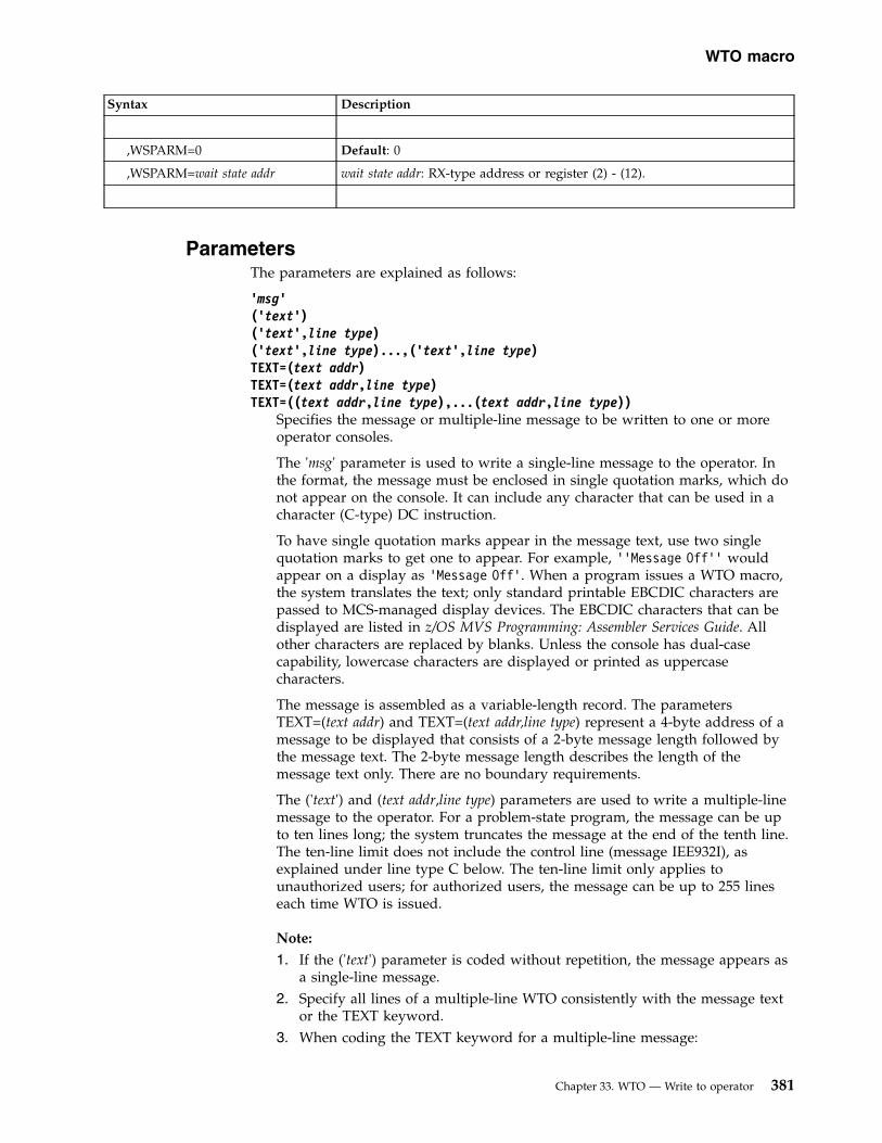
Syntax Description
,WSPARM=0 Default: 0
,WSPARM=wait state addr wait state addr: RX-type address or register (2) - (12).
ParametersThe parameters are explained as follows:
'msg'('text')('text',line type)('text',line type)...,('text',line type)TEXT=(text addr)TEXT=(text addr,line type)TEXT=((text addr,line type),...(text addr,line type))
Specifies the message or multiple-line message to be written to one or moreoperator consoles.
The 'msg' parameter is used to write a single-line message to the operator. Inthe format, the message must be enclosed in single quotation marks, which donot appear on the console. It can include any character that can be used in acharacter (C-type) DC instruction.
To have single quotation marks appear in the message text, use two singlequotation marks to get one to appear. For example, ’’Message Off’’ wouldappear on a display as ’Message Off’. When a program issues a WTO macro,the system translates the text; only standard printable EBCDIC characters arepassed to MCS-managed display devices. The EBCDIC characters that can bedisplayed are listed in z/OS MVS Programming: Assembler Services Guide. Allother characters are replaced by blanks. Unless the console has dual-casecapability, lowercase characters are displayed or printed as uppercasecharacters.
The message is assembled as a variable-length record. The parametersTEXT=(text addr) and TEXT=(text addr,line type) represent a 4-byte address of amessage to be displayed that consists of a 2-byte message length followed bythe message text. The 2-byte message length describes the length of themessage text only. There are no boundary requirements.
The ('text') and (text addr,line type) parameters are used to write a multiple-linemessage to the operator. For a problem-state program, the message can be upto ten lines long; the system truncates the message at the end of the tenth line.The ten-line limit does not include the control line (message IEE932I), asexplained under line type C below. The ten-line limit only applies tounauthorized users; for authorized users, the message can be up to 255 lineseach time WTO is issued.
Note:
1. If the ('text') parameter is coded without repetition, the message appears asa single-line message.
2. Specify all lines of a multiple-line WTO consistently with the message textor the TEXT keyword.
3. When coding the TEXT keyword for a multiple-line message:
WTO macro
Chapter 33. WTO — Write to operator 381

v Do not exceed the 71-character limit for the macro parameter value.v You can use the CONNECT parameter to connect subsequent lines of a
multiple-line message if you cannot fit them into one macro invocation.4. For a multiple-line message, you must clear register 0 on the first WTO
issuance.
The line type defines the type of information contained in the 'text' field ofeach line of the message:
C Indicates that the 'text' parameter is the text to be contained in thecontrol line of the message. The control line normally contains amessage title. C may only be coded for the first line of a multiple-linemessage. If this parameter is omitted and descriptor code 9 is coded,the system generates a control line (message IEE932I) containing only amessage identification number. The control line remains static whileyou scroll through all the lines of a multi-line message displayed on anMCS console (provided that the message is displayed in an out-of-linedisplay area). Control lines are optional.
L Indicates that the 'text' parameter is a label line. Label lines containmessage heading information; they remain static while you scrollthrough all the lines of a multi-line message displayed on an MCSconsole (provided that the message is displayed in an out-of-linedisplay area). Label lines are optional. If coded, lines must eitherimmediately follow the control line or another label line, or be the firstline of the multiple-line message if there is no control line. Only twolabel lines may be coded per message. See “Embedding Label Lines ina Multi-line Message” in z/OS MVS Programming: Authorized AssemblerServices Guide for additional information about how to include multiplelabel lines within a message.
D Indicates that the 'text' parameter contains the information to beconveyed to the operator by the multiple-line message. The data linesare paged while you scroll through all the lines of a multi-line messagedisplayed on an MCS console (provided that the message is displayedin an out-of-line display area).
DE Indicates that the 'text' parameter contains the last line of informationto be passed to the operator. Specify DE on the last line of text of theWTO. If there is no text on the last line, specify E.
E Indicates that the previous line of text was the last line of text to bepassed to the operator. The 'text' parameter, if any, coded with a linetype of E is ignored. Specify E on the last line of the WTO if that linehas no text. If the last line has text, specify DE.
,ROUTCDE=(routing code)Specifies the routing code or codes to be assigned to the message.
The routing codes are:
Code Meaning
1 Operator Action
The message indicates a change in the system status. It demands actionby the primary operator.
2 Operator Information
WTO macro
382 z/OS MVS Authorized Assembler Services Reference SET-WTO
The message indicates a change in system status. It does not demandaction; rather, it alerts the primary operator to a condition that mightrequire action.
This routing code is used for any message that indicates job statuswhen the status is not requested specifically by an operator inquiry. Itis also used to route processor and problem program messages to thesystem operator.
3 Tape Pool
The message gives information about tape devices, such as the statusof a tape unit or reel, the disposition of a tape reel, or a request tomount a tape.
4 Direct Access Pool
The message gives information about direct access storage devices(DASD), such as the status of a direct access unit or volume, thedisposition of a volume, or a request to mount a volume.
5 Tape Library
The message gives tape library information, such as a request byvolume serial numbers for tapes for system or problem program use.
6 Disk Library
The message gives disk library information, such as a request byvolume serial numbers for volumes for system or problem programuse.
7 Unit Record Pool
The message gives information about unit record equipment, such as arequest to mount a printer train.
8 Teleprocessing Control
The message gives the status or disposition of teleprocessingequipment, such as a message that describes line errors.
9 System Security
The message gives information about security checking, such as arequest for a password.
10 System/Error Maintenance
The message gives problem information for the system programmer,such as a system error, an uncorrectable I/O error, or informationabout system maintenance.
11 Programmer Information
This is commonly referred to as write to programmer (WTP). Themessage is intended for the problem programmer. This routing code isused when the program issuing the message cannot route the messageto the programmer through a system output (SYSOUT) data set. Themessage appears in the JESYSMSG data set. If the message is issued bya TSO user, the message is also sent to the TSO user's screen.
12 Emulation
The message gives information about emulation. (These messageidentifiers are not included in this publication.)
WTO macro
Chapter 33. WTO — Write to operator 383

13-20 For customer use only.
21-28 For subsystem use only.
29 Disaster recovery.
30-40 For IBM use only.
41 The message gives information about JES3 job status.
42 The message gives general information about JES2 or JES3.
43-64 For JES use only.
65-96 Messages associated with particular processors.
97-128 Messages associated with particular devices.
If you omit the ROUTCDE, DESC, and CONSID or CONSNAME keywords,the system uses the routing code specified on the ROUTCODE keyword on theDEFAULT statement in the CONSOLxx member of SYS1.PARMLIB.
Note: Routing codes 1, 2, 3, 4, 7, 8, 10, and 42 cause hard copy of the messagewhen display consoles are used, or more than one console is active. All otherrouting codes may go to hard copy as a PARMLIB option or as a result of aVARY HARDCPY command.
,DESC=(descriptor code)Specifies the message descriptor code or codes to be assigned to the message.Descriptor codes 1 through 6, 11 and descriptor code 12 are mutually exclusive.Codes 7 through 10, and 13, can be assigned in combination with any othercode.
The descriptor codes are:
Code Meaning
1 System Failure
The message indicates an error that disrupts system operations. Tocontinue, the operator must reIPL the system or restart a majorsubsystem. This causes the audible alarm to be issued.
2 Immediate Action Required
The message indicates that the operator must perform an actionimmediately. The message issuer could be in a wait state until theaction is performed or the system needs the action as soon as possibleto improve performance. The task waits for the operator to completethe action. This causes the audible alarm to be issued.
Note: When an authorized program issues a message with descriptorcode 2, a DOM macro must be issued to delete the message after therequested action is performed.
3 Eventual Action Required
The message indicates that the operator must perform an actioneventually. The task does not wait for the operator to complete theaction.
If the task can determine when the operator has performed the action,the task should issue a DOM macro to delete the message when theaction is complete.
4 System Status
WTO macro
384 z/OS MVS Authorized Assembler Services Reference SET-WTO

The message indicates the status of a system task or of a hardwareunit.
5 Immediate Command Response
The message is issued as an immediate response to a systemcommand. The response does not depend on another system action ortask.
6 Job Status
The message indicates the status of a job or job step.
7 Task-Related
The message is issued by an application or system program. Messageswith this descriptor code are deleted when the job step that issuedthem ends.
8 Out-of-Line
The message, which is one line of a group of one or more lines, is to bedisplayed out-of-line. If a message cannot be displayed out-of-linebecause of the device being used, descriptor code 8 is ignored, and themessage is displayed in-line with the other messages.
Note: Multiline messages directed at an OOL area and routed by eitherthe UNKNIDS or INTIDS attributes will be forced "inline".
9 Operator's Request
The message is written in response to an operator's request forinformation by a DEVSERV, DISPLAY, or MONITOR command.
10 Not defined
Descriptor code 10 is not currently in use.
11 Critical Eventual Action Required
The message indicates that the operator must perform an actioneventually, and the action is important enough for the message toremain on the display screen until the action is completed. The taskdoes not wait for the operator to complete the action. This causes theaudible alarm to be issued.
Avoid using this descriptor code for non-critical messages because thedisplay screen could become filled.
If the task can determine when the operator has performed the action,the task should issue a DOM macro to delete the message when theaction is complete.
12 Important Information
The message contains important information that must be displayed ata console, but does not require any action in response.
13 Automation Information
Indicates that this message was previously automated.
Action messages many have an * sign or @ sign displayed before the first characterof the message. The * sign indicates that the WTO was issued by an authorizedprogram. The @ sign indicates that the WTO was issued by an unauthorizedprogram.
WTO macro
Chapter 33. WTO — Write to operator 385

All WTO messages with descriptor codes 1, 2, or 11 are action messages that havean asterisk (*) sign displayed before the first character of the message. Thisindicates a need for operator action. These action messages will cause the audiblealarm to sound on operator consoles so-equipped. On operator consoles thatsupport color, descriptor codes determine the color in which a message should bedisplayed. Colors can indicate the type of action you need to take depending onyour installation setup. The colors used for different descriptor codes are describedin z/OS MVS System Commands.
The system holds messages with descriptor codes 1, 2, 3, or 11 until you deletethem. When you no longer need messages with descriptor codes 1, 2, 3, or 11, youshould delete those messages using the DOM macro. If messages with descriptorcodes 1, 2, 3, or 11 also have descriptor code 7, the system deletes themautomatically at task termination. For unauthorized issuers of WTOs, the systemadds descriptor code 7 to all messages with descriptor code 1 or 2. The system alsoadds descriptor code 7 to all WTORs.
If descriptor code 7 is specified, the system deletes the message automaticallywhen the job step that issued it ends.
The message processing facility (MPF) can suppress messages. For MPF tosuppress messages, the hardcopy log must be active. The suppressed messages donot appear on any console; they do appear on the hardcopy log.
,AREAID=id charSpecifies a display area of the console screen on which a multiple-line messageis to be written.
Valid area IDs are A through K and Z. A through K refer to out-of-line areasdefined on an MCS console by the CONTROL A command. The character Zdesignates the message area (the screen's general message area, rather than adefined display area); it is assumed if nothing is specified. The areas areexplained in z/OS MVS System Commands.
Note:
1. WTO ignores this keyword on single-line invocations.2. When you specify AREAID, you must specify descriptor codes 8 and 9.3. If you specify this parameter, the area could be overlaid by a currently
running dynamic display. Support for queuing messages with descriptorcode 8 is by console ID only. You must specify a console explicitly using theCONSID or CONSNAME parameters on WTO.
4. You can use the CONVCON macro to syntactically validate an area ID.
,MSGTYP=(msg type)Specifies how the message is to be routed to consoles on which the MONITORcommand is active. If you specify anything other than MSGTYP=N, which isthe default, your message will be routed according to your specification onMSGTYP.
For SESS, JOBNAMES, or STATUS, the message is to be routed to the consolethat issued the MONITOR SESS, MONITOR JOBNAMES, or MONITORSTATUS command, respectively. When the message type is identified by theoperating system, the message is routed to those consoles that requested theinformation.
For Y, the message type describes what functions (MONITOR SESS, MONITORJOBNAMES, and MONITOR STATUS) are desired. N, or omission of the
WTO macro
386 z/OS MVS Authorized Assembler Services Reference SET-WTO

MSGTYP parameter, indicates that the message is to be routed as specified inthe ROUTCDE parameter. Y creates an area in the WTO parameter list inwhich you can set message type information if you are coding a WTO withoutany of the following parameters:v KEYv TOKENv CONSIDv CONSNAMEv TEXTv CARTv LINKAGEv SYNCH
IBM recommends that you do not use MSGTYP=Y.
,MCSFLAG=(flag name)Specifies one or more flags whose meanings are shown below:
Table 45. MCSFLAG Flag Names
Flag Name Meaning
RESP The WTO is an immediate command response.
REPLY This WTO is a reply to a WTOR.
BRDCST Broadcast the message to all active consoles.
HRDCPY Queue the message for hard copy only.
NOTIME Do not append time to the message.
NOCPY Do not queue the message for hard copy.
CMD The WTO is a recording of a system command issued for hardcopy logpurposes.
Note:
1. MCSFLAG=HRDCPY and SYNCH=YES are mutually exclusive.2. Use DESC=5 rather than specifying MCSFLAG=RESP for WTO messages that
are immediate command response.
Note:
,CONNECT=connect fieldSpecifies a field containing the 4-byte message ID of the previous WTO towhich this WTO is to be connected. This message ID is obtained as an outputparameter (returned in register 1) from the previous WTO. If a register is used,it contains the address of the message ID.
CONNECT is valid only for continuation of multiple-line messages. When youspecify this parameter in the list form, code it as CONNECT= with nothingafter the equal sign.
This parameter is mutually exclusive with the CONSID, CONSNAME, andSYSNAME parameters.
Note: If you specify LINKAGE=SVC, you can still use register 0, as mentionedat the beginning of the WTO macro description, to connect WTO messages. Ifyou specify both register 0 and CONNECT, however, the system uses theCONNECT parameter. IBM suggests that you use the CONNECT parameter.
WTO macro
Chapter 33. WTO — Write to operator 387

,CONSID=console idSpecifies a 4-byte field containing the ID of the console to receive a message.
Note:
1. If you code the CONSID parameter using a register, the register mustcontain the console ID itself, rather than the address of the console ID.
2. When you code CONSID on the list form of WTO, code it as CONSID=with nothing after the equal sign.
3. CONSID is mutually exclusive with the CONNECT, CONSNAME, andSYSNAME parameters.
,CONSNAME=console nameSpecifies an 8-byte field containing a 2- through 8-character name, left-justifiedand padded with blanks, of the console to receive a message. When youspecify this parameter in the list form, code it as CONSNAME= with nothingafter the equal sign.
This parameter is mutually exclusive with the CONSID, CONNECT, andSYSNAME parameters.
,SYSNAME=system nameSpecifies an 8-byte input field containing a system name to be associated withthis message. You should left-justify SYSNAME and pad with blanks.
The system name is that of the system from which the caller issues the WTO.When you specify this parameter in the list form, code it as SYSNAME= withnothing after the equal sign. If SYSNAME is omitted, the system uses the nameof the system where the WTO is issued. IBM suggests that you avoid using theSYSNAME parameter.
This parameter is mutually exclusive with the CONNECT parameter.
,CART=cmd/resp tokenSpecifies an 8-character input field containing a command and response tokento be associated with this message. The command and response token is usedto associate user information with a command and its command response. Youcan supply any value as a command and response token. When you specifythis parameter in the list form, code it as CART= with nothing after the equalsign.
,KEY=keySpecifies an input field containing an 8-byte key to be associated with thismessage. The key must be EBCDIC if used with the MVS DISPLAY Rcommand for retrieval purposes, but it must not be ‘*’. The key must beleft-justified, and padded on the right with blanks. If a register is used, itcontains the address of the key. When you specify this parameter in the listform, code it as KEY= with nothing after the equal sign.
,TOKEN=tokenSpecifies an input field containing a 4-byte token to be associated with thismessage. This field is used to identify a group of messages that can be deletedby a DOM macro that includes TOKEN. The token must be unique within anaddress space and can be any value. When you specify this parameter in thelist form, code it as TOKEN= with nothing after the equal sign.
Note: When you code the TOKEN parameter using a register, the register mustcontain the token itself, rather than the address of the token.
,JOBID=job idSpecifies an 8-byte input field containing an ID that identifies the issuer of the
WTO macro
388 z/OS MVS Authorized Assembler Services Reference SET-WTO

WTO message. When you specify this parameter in the list form, code it asJOBID= with nothing after the equal sign.
,JOBNAME=jobnameSpecifies an 8-byte input field containing a name that identifies the issuer ofthe WTO message. You should left-justify JOBNAME and pad with blanks.When you specify this parameter in the list form, code it as JOBNAME= withnothing after the equal sign.
,LINKAGE=SVC,LINKAGE=BRANCH
Specifies how control is to pass to the WTO service.
LINKAGE=SVC indicates that the linkage is by a supervisor call. If LINKAGEis not specified, this is the default.
LINKAGE=BRANCH indicates that the linkage is by a branch-and-link. Thisparameter is used by programs that run at times when an SVC cannot beissued, and by programs that require the WTO request to be handledsynchronously.
When you specify this parameter in the list form, code it as LINKAGE= withnothing after the equal sign.
If you specify LINKAGE=BRANCH, you cannot put the CONNECT value inregister 0. You must use the CONNECT keyword.
,SYNCH=NO,SYNCH=YES
Specifies whether the WTO request processes synchronously with the caller.
SYNCH=NO, the default, indicates that the request is not processedsynchronously.
SYNCH=YES indicates that the request is to be processed synchronously. Thisparameter is used in error and recovery environments, when normal messageprocessing cannot be used. The message is sent to a console, where it is heldon the screen for up to ten seconds, before control is returned to the caller. Acopy of the message is queued for transcription to the hardcopy log.
If you specify SYNCH=YES:v You must specify the parameter LINKAGE=BRANCH.v The message text must be 14 lines or less.v The following parameters are mutually exclusive: CONNECT, AREAID, and
MCSFLAG=HRDCPY.
Important: Use caution when specifying SYNCH=YES. If your installation hasnot specified a SYNCHDEST console group in the CNGRPxx member ofparmlib, the system will display the WTO on the system console, located in theOperating System Messages task on the Hardware Management Console. All ofthe system’s CPs may be stopped while the message is being displayed (for upto ten seconds). See the “Display of Synchronous Messages” topic in z/OS MVSPlanning: Operations for more information about how z/OS displays thesemessages.
Your installation can determine which consoles can receive synchronousmessages by using the SYNCHDEST parameter in the CONSOLxx member ofSYS1.PARMLIB. For additional information on the SYNCHDEST parameter, seez/OS MVS Initialization and Tuning Reference.
,WSPARM=0
WTO macro
Chapter 33. WTO — Write to operator 389

,WSPARM=wait state addrSpecifies whether a wait state is associated with this message.
A value of zero indicates that there is no wait state associated with thismessage. If you do not specify WSPARM, this is the default.
A nonzero value indicates either the address of a LOADWAIT parameter list ora register containing a pointer to the parameter list. The LOADWAIT macrogenerates the LOADWAIT parameter list. When you specify this parameter inthe list form, code it as WSPARM= with nothing after the equal sign.
This parameter requires the SYNCH=YES and LINKAGE=BRANCHparameters.
ABEND codesWTO might abnormally terminate with abend code X’D23’. See z/OS MVS SystemCodes for an explanation and programmer response for this code.
Return and reason codesWhen the WTO macro returns control to your program, GPR 15 contains one of thefollowing hexadecimal return codes.
Table 46. Return codes for the WTO macro
Return Code Meaning and Action
00 Meaning: Processing completed successfully.
Action: None.
02 Meaning: Processing was not completely successful. This could be due toinconsistent parameters given to WTO, or it could be an environmental problem.
Action: A D23 abend has been issued for diagnostic purposes only. No dumphas been taken; if a dump is needed, you must set a SLIP trap. Correct anyinconsistencies in the WTO invocation.
04 Meaning: Program error. The length of text for a message line was not correct.
Action:
v Make sure your text is properly referenced. If you are using the TEXTparameter, make sure it is pointing to valid data.
v Make sure your message text is defined correctly. If you are using the TEXTparameter, make sure the first two bytes of data in the area pointed to by theTEXT parameter value contain the length of the message text.
In all cases, correct the problem and retry the request.
08 Meaning: Program error. The connecting message ID (passed in register 0 or asspecified by the CONNECT parameter value) does not match any on the queue.The request was ignored.
Action: Verify the connect ID value, correct the problem, and retry the request.
18 Meaning: Program error. The WPL was invalid and a symptom record waswritten to LOGREC to describe the error. The message was not processed.
Action: Correct the WPL.
30 Meaning: Environmental error. For routing code 11, the required resource wasnot available and the request was ignored. For any other routing code, therequest was processed.
Action: Retry the request when the resource you need is available.
WTO macro
390 z/OS MVS Authorized Assembler Services Reference SET-WTO

Table 46. Return codes for the WTO macro (continued)
Return Code Meaning and Action
40 Meaning: Environmental error. WTO was issued with LINKAGE=BRANCH;insufficient storage was available to queue the message for delayed issue. IfSYNCH=NO was specified, the message was not queued for delayed issue. IfSYNCH=YES was specified, the message was delivered for display, but notqueued for hardcopy.
Action: If you want the message to be delivered to the destination yourequested, reissue the request. If the message was an action message that wasnot displayed, a DOM request is not required.
44 Meaning: Environmental error. WTO was issued with LINKAGE=BRANCH,SYNCH=YES, or was issued during IPL processing; no usable console wasavailable. The message was only queued for hardcopy.
Action: If the message was issued during IPL, do not reissue the message. Ifafter IPL and you want the message to be delivered to the destination yourequested, reissue the request. If the message was an action message that wasnot displayed, a DOM request is not required.
48 Meaning: Environmental error. WTO was issued with LINKAGE=BRANCH,SYNCH=YES, or was issued during IPL processing; no usable console wasavailable and insufficient storage was available to queue the message fordelayed issue. The message was not delivered for display, nor queued forhardcopy.
Action: If the message was issued during IPL, do not reissue the message. Ifafter IPL and you want the message to be delivered to the destination yourequested, reissue the request. If the message was an action message that wasnot displayed, a DOM request is not required.
4C Meaning: Environmental error. WTO was issued with LINKAGE=BRANCH; nostorage was available for the use of WTO processing. If WSPARM=0, noprocessing was done. If WSPARM does not equal zero, WTO loaded the waitstate, but performed no other processing.
Action: If you want the message to be delivered to the destination yourequested, reissue the request. If the message was an action message that wasnot displayed, a DOM request is not required.
50 Meaning: Environmental error. The message could not be fully processedbecause of insufficient space. The message might not appear in the hardcopy logand it might not be displayed on any consoles.
Action: Retry the request.
54 Meaning: Environmental error. The message could not be fully processedbecause of a hardcopy failure. The message might not appear in the hardcopylog.
Action: Issue a D C,HC to display any active hardcopy mediums. Verify thatSYSLOG and OPERLOG are active and functioning correctly and then retry therequest.
58 Meaning: Environmental error. The message could not be fully processedbecause of an error that occurred while sending it. The message might notappear in the hardcopy log and it might not be displayed on any consoles.
Action: Retry the request.
5C Meaning: Environmental error. The message could not be fully processedbecause of a failure freeing storage. The message might not appear in thehardcopy log and it might not be displayed on any consoles.
Action: Retry the request.
60 Meaning: Environmental error. The message could not be fully processedbecause of an error that occurred while calculating its size. The message mightnot appear in the hardcopy log and it might not be displayed on any consoles.
Action: Retry the request.
WTO macro
Chapter 33. WTO — Write to operator 391

Table 46. Return codes for the WTO macro (continued)
Return Code Meaning and Action
64 Meaning: Environmental error. The message could not be fully processedbecause of an error that occurred while building the message. The messagemight not appear in the hardcopy log and it might not be displayed on anyconsoles.
Action: Retry the request.
68 Meaning: The WTO environment is not yet available. The message was notdelivered for display, nor was it queued for hardcopy.
Action: Issue the request again when WTO processing is available.
Example 1Issue an important information message to a console whose name is defined infield MYCONS. This message is issued using the branch-entry option.
WTO ’USR123I DO NOT SUBMIT JOBS REQUESTING THREE OR MORE TAPXES DURING FIRST SHIFT’,DESC=(12),CONSNAME=MYCONS,LINKAGE=BRANCH,SYNCH=NO
.
.
.MYCONS DC CL8’SCHDCONS’
Example 2Issue a multi-line message using the TEXT parameter. This is an importantinformation message which does not have a time stamp and is not sent to thehardcopy log.
WTO TEXT=((REMIND1,D),(REMIND2,D),(REMIND3,DE)), XDESC=(12),MCSFLAG=(NOTIME,NOCPY)
.
.
.REMIND1 DC AL2(L’RMD1TXT)RMD1TXT DC C’USR003I REMINDER: THE SYSTEM IS NOT AVAILABLE FOR USEX
ON THIRD SHIFT’REMIND2 DC AL2(L’RMD2TXT)RMD2TXT DC C’FOR SPECIAL REQUESTS CONTACT SYSTEM SUPPORT’REMIND3 DC AL2(L’RMD3TXT)RMD3TXT DC C’CALL THE STATUS DESK FOR FURTHER INFORMATION’
Example 3To prevent parameter lists that are not valid from causing system errors, the WTOservice records the errors as symptom records in LOGREC. Here is a samplesymptom record:THE SYMPTOM RECORD DOES NOT CONTAIN A SECONDARY SYMPTOM STRING.FREE FORMAT COMPONENT INFORMATION:
KEY = F000 LENGTH = 000024 (0018)+000 C9D5C3D6 D9D9C5C3 E340E6E3 D640C9D5 |INCORRECT WTO IN|+010 E5D6C3C1 E3C9D6D5 |VOCATION |KEY = F000 LENGTH = 000010 (000A)+000 C1E4E3C8 D6D9C9E9 C5C4 |AUTHORIZED |KEY = F000 LENGTH = 000009 (0009)+000 C1E2C9C4 61F0F0F0 F1 |ASID/0001 |KEY = F000 LENGTH = 000016 (0010)+000 D1D6C2D5 C1D4C561 5CD4C1E2 E3C5D95C |JOBNAME/*MASTER*|KEY = F000 LENGTH = 000025 (0019)+000 C9D5E5D6 D2C5D961 C9C5C5C3 C2F9F9F9 |INVOKER/IEECB999|+010 4EF0F0F0 F0F4C5C4 F2 |+00004ED2 |
WTO macro
392 z/OS MVS Authorized Assembler Services Reference SET-WTO

KEY = F000 LENGTH = 000032 (0020)+000 C5D5C4D3 C9D5C540 C4C5E3C5 C3E3C5C4 |ENDLINE DETECTED|+010 40C2C5C6 D6D9C540 E6D7D3D3 C9D5C5E2 | BEFORE WPLLINES|KEY = F000 LENGTH = 000017 (0011)+000 C3E4D9D9 C5D5E340 D3C9D5C5 61F0F0F0 |CURRENT LINE/000|+010 F2 |2 |KEY = F000 LENGTH = 000003 (0003)+000 E6D7D3 |WPL |KEY = FF00 LENGTH = 000216 (00D8)+000 00480050 F0F0F2F2 40C5D5C1 C2D3C5C4 |...&0022 ENABLED|+010 4040F0F0 F2F340C5 D5C1C2D3 C5C44040 | 0023 ENABLED |+020 F0F0F2F4 40C5D5C1 C2D3C5C4 4040F0F0 |0024 ENABLED 00|+030 F2F540C5 D5C1C2D3 C5C44040 F0F0F2F6 |25 ENABLED 0026|+040 40C5D5C1 C2D3C5C4 0400007C 10000000 | ENABLED...@....|+050 00000000 00000000 000004D2 00000000 |...........K....|+060 LENGTH(0048) ==> ALL BYTES CONTAIN X’00’.+090 00000000 40404040 40404040 00000000 |.... ....|+0A0 LENGTH(0032) ==> ALL BYTES CONTAIN X’00’.+0C0 00000000 2000C103 00103000 F0F0F2F7 |......A.....0027|+0D0 40C5D5C1 C2D3C5C4 | ENABLED |KEY = F000 LENGTH = 000010 (000A)+000 D4C1D1D6 D940E3C5 E7E3 |MAJOR TEXT |KEY = F000 LENGTH = 000034 (0022)+000 40C9C5C5 F7F3F5C9 40F1F74B F2F74BF3 | IEE000I 17.27.3|+010 F940C4E4 D4D4E840 C4C9E2D7 D3C1E840 |9 DUMMY DISPLAY |+020 F2F3F4 |234 |
This symptom record indicates that this is a WTO error. It also indicates whetherthe WTO issuer was authorized. The symptom record also contains the followinginformation:v The ASID, job name, program name, and an offset into the program that issued
the WTO. You can use this information to help identify the issuerv A description of the errorv The message line number where the error was detectedv The text of the first line, if the message is a multi-line WTO
Once you diagnose the reason for the error, correct the WTO invocation to issuethe message properly, or contact the owner of the application that is issuing theWTO to have it corrected.
WTO - List formUse the list form of the WTO macro together with the execute form of the macrofor applications that require reentrant code. The list form of the macro defines anarea of storage, which the execute form of the macro uses to store the parameters.
SyntaxThe list form of the WTO macro is written as follows:
Syntax Description
name name: Symbol. Begin name in column 1.
⌂ One or more blanks must precede WTO.
WTO
WTO macro
Chapter 33. WTO — Write to operator 393

Syntax Description
⌂ One or more blanks must follow WTO.
'msg' msg: Up to 126 characters.
('text') text: Up to 126 characters.
('text',line type) Note:
1. If you code 'msg' or ('text'...), it must be the first parameter you code.
2. For a single-line WTO, the parameter value is not required on TEXT forthe list form. Code only TEXT=. Then code TEXT=(text addr) on theexecute form.
TEXT=
TEXT=((,line type),(,line type),...(,linetype))
The permissible line types, text lengths, and maximum numbers of each linetype are shown below:
line type text maximum numberC 35 char 1 C typeL 71 char 2 L typeD 71 char 255 D typeDE 71 char 1 DE type
orE None 1 E type
The maximum total number of lines that can be coded in one instruction is255.
,ROUTCDE=(routing code) routing code: Decimal digit from 1 to 128. The routing code is one or morecodes, separated by commas, or a hyphen to indicate a range.
,DESC=(descriptor code) descriptor code: Decimal digit from 1 to 13. The desc code is one or morecodes, separated by commas.
,AREAID=id char id char: Alphabetic character A - K, Z.
,MSGTYP=(msg type) msg type: Any of the following
N SESS,JOBNAMES
Y SESS,STATUS
SESS JOBNAMES,STATUS
JOBNAMESSESS,JOBNAMES,STATUS
STATUS
Note: IBM recommends that you do not use MSGTYP=Y. See the MSGTYPexplanation on page “,MSGTYP=(msg type)” on page 386 for moreinformation.
WTO macro
394 z/OS MVS Authorized Assembler Services Reference SET-WTO

Syntax Description
,MCSFLAG=(flag name) flag name: Any combination of the following, separated by commas:
CMD HRDCPY
RESP NOCPY
REPLY NOTIME
BRDCST
,CONNECT= Parameter value not required for list form. Code only ,CONNECT=. If youcode CONNECT on the execute form of WTO, you must code the sameparameter on the list form.
,CONSID= Parameter value not required for list form. Code only ,CONSID= (or,CONSNAME=). If you code CONSID (or CONSNAME) on the executeform of WTO, you must code the same parameter on the list form.
,CONSNAME=
,SYSNAME= Parameter value not required for list form. Code only ,SYSNAME=. If youcode SYSNAME on the execute form of WTO, you must code the sameparameter on the list form.
,CART= Parameter value not required for list form. Code only ,CART=. If you codeCART on the list form of WTO, you must code CART on the execute form.
,KEY= Parameter value not required for list form. Code only ,KEY=. If you codeKEY on the list form of WTO, you must code KEY on the execute form.
,TOKEN= Parameter value not required for list form. Code only ,TOKEN=. If you codeTOKEN on the list form of WTO, you must code TOKEN on the executeform.
,JOBID= Parameter value not required for list form. Code only ,JOBID=. If you codeJOBID on the list form of WTO, you must code JOBID on the execute form.
,JOBNAME= Parameter value not required for list form. Code only ,JOBNAME=. If youcode JOBNAME on the list form of WTO, you must code JOBNAME on theexecute form.
,LINKAGE= Parameter value not required for list form. Code only ,LINKAGE=. If youcode LINKAGE on the list form of WTO, you must code LINKAGE on theexecute form.
,SYNCH=NO Default: NO
,SYNCH=YES
WTO macro
Chapter 33. WTO — Write to operator 395

Syntax Description
,WSPARM= Parameter value not required for list form. Code only ,WSPARM=. If youcode WSPARM on the list form of WTO, you must code WSPARM on theexecute form.
,MF=L
ParametersThe parameters are explained under the standard form of the WTO macro with thefollowing exception:
,MF=LSpecifies the list form of the WTO macro.
WTO - Execute formUse the execute form of the WTO macro together with the list form of the macrofor applications that require reentrant code. The execute form of the macro storesthe parameters into the storage area defined by the list form.
The message cannot be modified on the execute form of the macro if you codeinline text (‘msg’ or (‘text’...)) on the list form.
SyntaxThe execute form of the WTO macro is written as follows:
Syntax Description
name name: Symbol. Begin name in column 1.
⌂ One or more blanks must precede WTO.
WTO
⌂ One or more blanks must follow WTO.
TEXT=(text addr)
TEXT=((text addr,),(text addr,),...(text addr,))
text addr: RX-type address or register (2) - (12).Note:
1. If you code TEXT=(text addr) on the execute form ofWTO, you must code TEXT= on the list form.
2. If you specify inline text on the list form (‘msg’ or(‘text’...)), do not code the TEXT keyword on theexecute form.
WTO macro
396 z/OS MVS Authorized Assembler Services Reference SET-WTO

Syntax Description
,CONNECT=connect field connect field: RX-type address or register (2) - (12). If youcode CONNECT on the execute form of WTO, you mustcode the same parameter on the list form.
,CONSID=console id console id: RX-type address or register (2) - (12).
,CONSNAME=console name console name: RX-type address or register (2) - (12).
If you code CONSID (or CONSNAME) on the executeform of WTO, you must code the same parameter on thelist form.
,SYSNAME=system name system name: RX-type address or register (2) - (12). If youcode SYSNAME on the execute form of WTO, you mustcode the same parameter on the list form.
,CART=cmd/resp token cmd/resp token: RX-type address or register (2) - (12). Ifyou code CART on the execute form of WTO, you mustcode CART on the list form.
,KEY=key key: RX-type address or register (2) - (12). If you codeKEY on the execute form of WTO, you must code KEYon the list form.
,TOKEN=token token: RX-type address or register (2) - (12). If you codeTOKEN on the execute form of WTO, you must codeTOKEN on the list form.
,JOBID=job id job id: RX-type address or register (2) - (12). If you codeJOBID on the execute form of WTO, you must codeJOBID on the list form.
,JOBNAME=jobname jobname: RX-type address or register (2) - (12). If youcode JOBNAME on the execute form of WTO, you mustcode JOBNAME on the list form.
,LINKAGE=SVC Default: SVC
,LINKAGE=BRANCH If you code LINKAGE on the execute form of WTO, youmust code LINKAGE on the list form.
,SYNCH=NO Default: NO
,SYNCH=YES
,WSPARM=0 Default: 0
,WSPARM=wait state addr wait state addr: RX-type address or register (2) - (12).
If you code WSPARM on the execute form of WTO, youmust code WSPARM on the list form.
WTO macro
Chapter 33. WTO — Write to operator 397

Syntax Description
,MF=(E,list addr) list addr: RX-type address, or register (1) - (12).
ParametersThe parameters are explained under the standard form of the WTO macro, withthe following exception:
,MF=(E, list addr)Specifies the execute form of the WTO macro.
list addr specifies the area that the system uses to store the parameters.
ExampleWrite a message with a prebuilt parameter list pointed to by register 1.WTO MF=(E,(1))
WTO macro
398 z/OS MVS Authorized Assembler Services Reference SET-WTO

Chapter 34. WTOR — Write to operator with reply
DescriptionThe WTOR macro causes a message requiring a reply to be written to one or moreoperator consoles and the hardcopy log. The macro also provides the informationrequired by the system to return the reply to the issuing program. See z/OS MVSProgramming: Authorized Assembler Services Guide for more information on using theWTOR macro.
The description of the WTOR macro follows. The WTOR macro is also described inz/OS MVS Programming: Assembler Services Reference IAR-XCT, with the exception ofthe MSGTYP, SYSNAME, JOBID, JOBNAME, LINKAGE, and SYNCH parameters.
EnvironmentIf you code LINKAGE=SVC, the requirements for the caller are:
Environmental factor RequirementMinimum authorization: One of the following, depending on the parameters you
code:
v Problem state and PSW key 0-7.
v If you code the MSGTYP, SYSNAME, JOBID, JOBNAME,and SYNCH parameters, one of the following:
– Supervisor state with PSW key 0-7
– APF-authorizedDispatchable unit mode: TaskCross memory mode: PASN=HASN=SASNAMODE: 24- or 31- or 64-bitASC mode: PrimaryInterrupt status: Enabled for I/O and external interrupts.Locks: No locks heldControl parameters: Must be in the primary address space
If you code LINKAGE=BRANCH, the requirements for the caller are:
Environmental factor RequirementMinimum authorization: Supervisor state with PSW key 0-7Dispatchable unit mode: Task or SRBCross memory mode: Any PASN, any HASN, any SASNAMODE: 24- or 31-bitASC mode: PrimaryInterrupt status: Enabled or disabled for I/O and external interrupts.Locks: The caller may hold locks, but is not required to hold any.Control parameters: Must be in the primary address space.
Programming requirementsBe aware of the following when coding the WTOR macro:v IBM recommends that you begin the parameter list for WTOR on a fullword
boundary.
© Copyright IBM Corp. 1988, 2017 399

v If the caller is disabled, the WTOR parameter list, reply area, and reply ECBmust be in fixed storage. In this case, LINKAGE=BRANCH and SYNCH=YESmust be specified.
v If the list and execute forms of the WTOR macro are in separate modules, bothmodules must be assembled or compiled with the same level of WTOR.
v When you're coding a reentrant program, make sure the WTOR parameter list isgenerated correctly. To ensure this, you must code the same parameters on bothforms, only when you code one or more of the following parameters:– RPLYISUR– CONSID– CONSNAME– SYSNAME– CART– KEY– TOKEN– JOBNAME– JOBID– LINKAGEOn the list form, code only the parameter and the equal sign; do not code aparameter value as well. If you specify parameter values on the list form, thesystem issues an MNOTE and ignores the data.
v For any WTOR keywords that allow a register specification, the value must beright-justified in the register.
v If you specify the TEXT keyword for a multi-line WTOR, you must code itsparameters in the following way:– On the list form, omit text addr for each line, but include line type. If you
specify text addr, the system ignores the data and issues an MNOTE.– On the execute form, omit line type for each line, but include text addr.
v To prevent parameter lists that are not valid from causing system errors, theWTOR service records the errors as symptom records in LOGREC. One exampleof an invalid parameter list is an invalid combination of WTOR parameters. Thesystem may also issue a D23 abend for diagnostic purposes only; the programissuing the WTOR will not be abended. Message processing will continue as faras possible using the invalid parameter list.Because of these invalid parameter list errors, you might notice that somemessages that you once were able to process can no longer be processed; yourprogram may also receive different return codes. However, in these cases, thesymptom record will always be issued, and the diagnostic D23 abend will beissued if possible. IBM suggests that you correct all WTOR errors, regardless ofwhether or not the message is actually displayed. For an example LOGRECsymptom record, see “Example 3” on page 392 in the WTO description.If a dump is needed along with the diagnostic D23 abend to debug the problem,the following SLIP can be set to cause dumps to be taken:SLIP SET,ENABLE,COMP=D23,ACTION=SVCD,END
Restrictionsv The caller cannot have an EUT FRR established.v If the LINKAGE=BRANCH parameter is specified, the SYNCH=YES parameter
is required.
WTOR macro
400 z/OS MVS Authorized Assembler Services Reference SET-WTO

v You can issue a multi-line WTOR only if you specify LINKAGE=BRANCH,SYNCH=YES.
v Issue a synchronous message only if your program is in a state in which itcannot issue an ordinary WTOR (LINKAGE=SVC), and you must receiveoperator input before continuing.
Important: Use caution when specifying SYNCH=YES. If your installation has notspecified a SYNCHDEST console group in the CNGRPxx member of parmlib, thesystem will display the WTOR on the system console, located in the OperatingSystem Messages task on the Hardware Management Console. All of the system’sCPs may be stopped while waiting for the operator to reply. See the “Display ofSynchronous Messages” topic in z/OS MVS Planning: Operations for moreinformation about how z/OS displays these messages.
Input register informationBefore issuing the WTOR macro, the caller does not have to place any informationinto any register unless using it in register notation for a particular parameter, orusing it as a base register.
Output register informationWhen control returns to the caller, the general purpose registers (GPRs) contain:
RegisterContents
0 Used as a work register by the system
1 Message identification number if the macro completed normally (you canuse this number to delete the message when it is no longer needed);otherwise, used as a work register by the system
2-13 Unchanged
14 Used as a work register by the system
15 Return code
When control returns to the caller, the access registers (ARs) contain:
RegisterContents
0-1 Used as work registers by the system
2-13 Unchanged
14-15 Used as work registers by the system
Some callers depend on register contents remaining the same before and afterissuing a service. If the system changes the contents of registers on which the callerdepends, the caller must save them before issuing the service, and restore themafter the system returns control.
Performance implicationsSYNCH=YES causes the system to display the message, disable the issuingprogram and system, and then synchronously provide the reply to the program. Ifyour installation has not specified a SYNCHDEST console group in the CNGRPxxmember of parmlib, the system will display the WTOR on the system console,
WTOR macro
Chapter 34. WTOR — Write to operator with reply 401

located in the Operating System Messages task on the Hardware ManagementConsole. All of the system’s CPs may be stopped while waiting for the operator toreply.
SyntaxThe standard form of the WTOR macro is written as follows:
Syntax Description
name name: Symbol. Begin name in column 1.
⌂ One or more blanks must precede WTOR.
WTOR
⌂ One or more blanks must follow WTOR.
‘msg’,reply addr,reply length,ecb addr
(‘text’,reply addr,reply length,ecb addr)
((‘text’,line type),...(‘text’,line type)),reply addr, replylength,ecb addr
TEXT=(text addr,reply addr,reply length,ecb addr)
TEXT=((text addr,line type),reply addr, reply length,ecb addr)
TEXT=(((text addr,line type),...(text addr, line type)), replyaddr,reply length,ecb addr)
Note: If you code ‘msg’... or (‘text’...), it must be the firstparameter you code.
msg: Up to 122 characters.
text: Up to 122 characters.
text addr: RX-type address or register (2) - (12).
reply addr: A-type address, or register (2) - (12).
reply length: Symbol, decimal digit, or register (2) - (12).The minimum length is 1; the maximum length is 119.
ecb addr: A-type address, or register (2) - (12).
The permissible line types, text lengths, and maximumnumbers are shown below:
line type text maximum numberC 31 char 1 C typeL 66 char 2 L typeD 66 char 14 D typeDE 66 char 1 DE type
orE None 1 E type
The maximum total of lines that can be coded in oneinstruction is 14.
WTOR macro
402 z/OS MVS Authorized Assembler Services Reference SET-WTO

Syntax Description
,ROUTCDE=(routing code) routing code: Decimal digit from 1 to 128. The routing codeis one or more codes, separated by commas, or a hyphento indicate a range.
,DESC=(descriptor code) descriptor code: Decimal number 7 or 13. If you code both7 and 13, separate them with commas.
,MSGTYP=(msg type) msg type: Any of the following:
N SESS,JOBNAMES
Y SESS,STATUS
SESS JOBNAMES,STATUS
JOBNAMESSESS,JOBNAMES,STATUS
STATUS
Note: IBM recommends that you do not use MSGTYP=Y.See the MSGTYP explanation on page “,MSGTYP=(msgtype)” on page 407 for more information.
,MCSFLAG=(flag name) flag name: Any combination of the following, separatedby commas:
NOCPYHRDCPY
RESP BRDCST
REPLY NOTIME
,RPLYISUR=reply console reply console: RX-type address or register (2) - (12).
,CONSID=console id console id: RX-type address or register (2) - (12).
,CONSNAME=console name console name: RX-type address or register (2) - (12).
,SYSNAME=system name system name: RX-type address or register (2) - (12).
,CART=cmd/resp token cmd/resp token: RX-type address or register (2) - (12).
,KEY=key key: RX-type address or register (2) - (12).
,TOKEN=token token: RX-type address or register (2) - (12).
,JOBID=job id job id: RX-type address or register (2) - (12).
,JOBNAME=jobname jobname: RX-type address or register (2) - (12).
WTOR macro
Chapter 34. WTOR — Write to operator with reply 403

Syntax Description
,LINKAGE=SVC Default: SVC
,LINKAGE=BRANCH
,SYNCH=NO Default: NO
,SYNCH=YES
ParametersThe parameters are explained as follows:
‘msg’,reply addr,reply length,ecb addr(‘text’,reply addr,reply length,ecb addr)((‘text’,line type,...‘text’,line type),reply addr,reply length,ecb addr)TEXT=(text addr,reply addr,reply length,ecb addr)TEXT=((text addr,line type),reply addr,reply length,ecb addr)TEXT=(((text addr,line type),...(text addr, line type)),reply addr,replylength,ecb addr)
Specifies the message or multiple-line message to be written to one or moreoperator consoles.
Use the ‘msg’ parameter to write a single-line message to the operator. Enclosethe message in apostrophes. The apostrophes do not appear on the console.You can include any character that can be used in a character (C-type) DCinstruction.
To have apostrophes appear in the message text, use two apostrophes to getone to appear. For example, ''Message Off'' would appear on a display as'Message Off'. When a program issues a WTOR macro, the system translatesthe text; only standard printable EBCDIC characters are passed toMCS-managed display devices. The EBCDIC characters that can be displayedare listed in “Timing and Communication” in z/OS MVS Programming:Assembler Services Guide. All other characters are replaced by blanks. Unless theconsole has dual-case capability, lowercase characters are displayed or printedas uppercase characters.
The message is assembled as a variable-length record. text addr represents a4-byte address of a message to be displayed that consists of a 2-byte messagelength followed by the message text. The 2-byte message length describes thelength of the message text only. There are no boundary requirements.
Use the parameters (‘text’) and (text addr,line type) to write a multiple-linemessage to the operator. For an authorized program, the message can be up tofourteen lines long; the system truncates the message at the end of thefourteenth line. The fourteen-line limit does not include the control line(message IEE932I), as explained under line type C below.
Note:
1. You can issue a multi-line WTOR only if you specify SYNCH=YES. See theSYNCH parameter description for information about its use.
2. If you code the parameter (‘text’) without repetition, the message appearsas a single-line message.
WTOR macro
404 z/OS MVS Authorized Assembler Services Reference SET-WTO

3. Specify all lines of a multiple-line WTOR consistently with the message textor the TEXT keyword. When coding the TEXT keyword for a multiple-linemessage, do not exceed the 66-character limit for the macro parametervalue.
The line type defines the type of information contained in the ‘text’ field ofeach line of the message:
C Indicates that the ‘text’ parameter is the text to be contained in thecontrol line of the message. The control line normally contains amessage title. C may be coded only for the first line of a multiple-linemessage. Control lines are optional.
L Indicates that the 'text' parameter is a label line. Label lines containmessage heading information. Label lines are optional. If coded, linesmust either immediately follow the control line or another label line orbe the first line of the multiple-line message if there is no control line.Only two label lines may be coded per message.
D Indicates that the ‘text’ parameter contains the information to beconveyed to the operator by the multiple-line message.
DE Indicates that the ‘text’ parameter contains the last line of informationto be passed to the operator. Specify DE on the last line of text of theWTOR. If there is no text on the last line, specify E.
E Indicates that the previous line of text was the last line of text to bepassed to the operator. The ‘text’ parameter, if any, coded with a linetype of E is ignored. Specify E on the last line of the WTOR if that linehas no text. If the last line has text, specify DE.
Note: All WTOR messages are action messages. An indicator (* for authorizedissuers or @ for unauthorized issuers) appears before the first character of anaction message to indicate a need for operator action. Action messages willcause the audible alarm to sound on operator consoles so-equipped.
reply addr specifies the address in virtual storage of the area into which thesystem is to place the reply. The reply is left-justified at this address.
reply length specifies the maximum length, in bytes, of the reply message.
ecb addr specifies the address of the event control block (ECB) to be used by thesystem to indicate the completion of the reply. The ECB address must point toa fullword boundary. After the system receives the reply, the ECB appears asfollows:Offset Length(bytes) Contents0 1 Completion code
Note: Use RPLYISUR to obtain the 4-byte console ID and console name of theconsole issuing the reply.
,ROUTCDE=(routing code)Specifies the routing code or codes to be assigned to the message.
The routing codes are:
Code Meaning
1 Operator Action
The message indicates a change in the system status. It demands actionby the primary operator.
WTOR macro
Chapter 34. WTOR — Write to operator with reply 405

2 Operator Information
The message indicates a change in system status. It does not demandaction; rather, it alerts the primary operator to a condition that mightrequire action.
This routing code is used for any message that indicates job statuswhen the status is not requested specifically by an operator inquiry. Itis also used to route processor and problem program messages to thesystem operator.
3 Tape Pool
The message gives information about tape devices, such as the statusof a tape unit or reel, the disposition of a tape reel, or a request tomount a tape.
4 Direct Access Pool
The message gives information about direct access storage devices(DASD), such as the status of a direct access unit or volume, thedisposition of a volume, or a request to mount a volume.
5 Tape Library
The message gives tape library information, such as a request byvolume serial numbers for tapes for system or problem program use.
6 Disk Library
The message gives disk library information, such as a request byvolume serial numbers for volumes for system or problem programuse.
7 Unit Record Pool
The message gives information about unit record equipment, such as arequest to mount a printer train.
8 Teleprocessing Control
The message gives the status or disposition of teleprocessingequipment, such as a message that describes line errors.
9 System Security
The message gives information about security checking, such as arequest for a password.
10 System/Error Maintenance
The message gives problem information for the system programmer,such as a system error, an uncorrectable I/O error, or informationabout system maintenance.
11 Programmer Information
This is commonly referred to as write to programmer (WTP). Themessage is intended for the problem programmer. This routing code isused when the program issuing the message cannot route the messageto the programmer through a system output (SYSOUT) data set. Themessage appears in the JESYSMSG data set. If the message issuer is aTSO user, the message is also displayed on the TSO user's screen.
12 Emulation
WTOR macro
406 z/OS MVS Authorized Assembler Services Reference SET-WTO

The message gives information about emulation. (These messageidentifiers are not included in this publication.)
13-20 For customer use only.
21-28 For subsystem use only.
29 Disaster recovery.
30-40 For IBM use only.
41 The message gives information about JES3 job status.
42 The message gives general information about JES2 or JES3.
43-64 For JES use only.
65-96 Messages associated with particular processors.
97-128 Messages associated with particular devices.
If you omit the ROUTCDE, and CONSID or CONSNAME keywords, thesystem uses the routing code specified on the ROUTCODE keyword on theDEFAULT statement in the CONSOLxx member of SYS1.PARMLIB. See z/OSMVS Initialization and Tuning Reference for information about CONSOLxx.
,DESC=(descriptor code)Specifies the message descriptor code or codes to be assigned to the message.Valid descriptor codes for the WTOR macro are:
7 Retain action message for life-of-task
13 Message previously automated
All WTOR messages are action messages that have an asterisk (*) signdisplayed before the first character (WTORs for unauthorized users have an"@" sign displayed before the first character). This indicates a need for operatoraction.
The system adds descriptor code 7 to all WTOR messages. The system holdsall WTOR messages until one of the following events occurs:v The system deletes the WTOR message when the reply is received.v You delete the WTOR message using the DOM macro. You should delete
any unanswered WTOR messages that are no longer current.v The system deletes the WTOR message at task termination.
The message processing facility (MPF) can suppress messages. For MPF tosuppress messages, the hardcopy log must be active. The suppressed messagesdo not appear on any console; they do appear on the hardcopy log.
,MSGTYP=(msg type)Specifies how the message is to be routed to consoles on which the MONITORcommand is active. If you specify anything other than MSGTYP=N, which isthe default, your message is routed according to your specification onMSGTYP.
For SESS, JOBNAMES, or STATUS, the message is to be routed to the consolethat issued the MONITOR SESS, MONITOR JOBNAMES, or MONITORSTATUS command, respectively. When the message type is identified by theoperating system, the message is routed to only those consoles that requestedthe information.
For Y or N, the message type describes what functions (MONITOR SESS,MONITOR JOBNAMES, and MONITOR STATUS) are desired. N, or omissionof the MSGTYP parameter, indicates that the message is to be routed as
WTOR macro
Chapter 34. WTOR — Write to operator with reply 407

specified in the ROUTCDE parameter. Y creates an area in the WTO parameterlist in which you can set message type information if you are coding a WTORwithout any of the following parameters:v KEYv TOKENv CONSIDv CONSNAMEv TEXTv RPLYISURv CARTv LINKAGEv SYNCH
IBM recommends that you do not use MSGTYP=Y.
,MCSFLAG=(flag name)Specifies one or more flag names whose meanings are shown below:
Table 47. MCSFLAG Flag Names
Flag Name Meaning
RESP The WTOR is an immediate command response.
REPLY This is a reply to a WTOR.
BRDCST Broadcast the message to all active consoles.
HRDCPY Queue the message for hard copy only.
NOTIME Do not append time to the message.
NOCPY Do not queue the message for hard copy.
,RPLYISUR=reply consoleSpecifies a 12-byte field where the system will place the 8-byte console nameand the 4-byte console ID of the console through which the operator replies tothis message. When you specify this keyword in the list form, code it asRPLYISUR= with nothing after the equal sign.
,CONSID=console idSpecifies a 4-byte field containing the ID of the console to receive a message.
Note:
1. If you code the CONSID parameter using a register, the register mustcontain the console ID itself, rather than the address of the console ID.
2. When you code CONSID on the list form of WTOR, code it as CONSID=with nothing after the equal sign.
3. CONSID is mutually exclusive with the CONSNAME parameter.
,CONSNAME=console nameSpecifies an 8-byte field containing a 2- through 8-character name, left-justifiedand padded with blanks, of the console to receive a message. This parameter ismutually exclusive with the CONSID parameter. When you specify thiskeyword in the list form, code it as CONSNAME= with nothing after the equalsign.
,SYSNAME=system nameSpecifies an 8-byte input field containing a system name to be associated withthis message. You should left-justify SYSNAME and pad with blanks.
WTOR macro
408 z/OS MVS Authorized Assembler Services Reference SET-WTO

The system name is that of the system from which the caller issues the WTORmessage. When you specify this parameter in the list form, code it asSYSNAME= with nothing after the equal sign. The system will, by default, setthe system name to the system where the message is issued. IBM suggests thatyou avoid specifying SYSNAME.
,CART=cmd/resp tokenSpecifies an 8-byte field containing a command and response token to beassociated with this message. You can specify any value as a command andresponse token. The command and response token is used to associate userinformation with a command and its command response. When you specifythis keyword in the list form, code it as CART= with nothing after the equalsign.
,KEY=keySpecifies a field containing an 8-byte key to be associated with this message.The key must be EBCDIC if used with the MVS DISPLAY R command forretrieval purposes, but it must not be ‘*’. The key must be left-justified andpadded on the right with blanks. If a register is used, it contains the address ofthe key. When this keyword is specified in the list form, it must be coded asKEY= with nothing after the equal sign.
,TOKEN=tokenSpecifies a field containing a 4-byte token to be associated with this message.This field is used to identify a group of messages that can be deleted by aDOM macro that includes TOKEN. The token must be unique within anaddress space, and can be any value. When you specify this keyword on thelist form, code it as TOKEN= with nothing after the equal sign.
Note: When you code the TOKEN parameter using a register, the register mustcontain the token itself, rather than the address of the token.
,JOBID=job idSpecifies an 8-byte input field containing an ID that specifies the issuer of theWTOR message. When you specify this parameter in the list form, code it asJOBID= with nothing after the equal sign.
,JOBNAME=jobnameSpecifies an 8-byte input field containing a name that specifies the issuer of theWTOR message. You should left-justify JOBNAME and pad with blanks. Whenyou specify this parameter in the list form, code it as JOBNAME= with nothingafter the equal sign.
,LINKAGE=SVC,LINKAGE=BRANCH
Specifies how control is to pass to the WTOR service.
LINKAGE=SVC indicates the linkage is by a supervisor call. If LINKAGE isnot specified, this is the default.
LINKAGE=BRANCH indicates the linkage is by a branch-and-link. You mustuse SYNCH=YES with this parameter. This parameter is used by programs thatrequire the WTOR request to be handled synchronously.
When you specify this keyword in the list form, code it as LINKAGE= withnothing after the equal sign.
,SYNCH=NO,SYNCH=YES
Specifies whether the WTOR request processes synchronously with the caller.
WTOR macro
Chapter 34. WTOR — Write to operator with reply 409

SYNCH=NO, the default, indicates that the request is not processedsynchronously.
SYNCH=YES indicates the request is to be processed synchronously. Thisparameter is used in error and recovery environments, when normal messageprocessing cannot be used. The message is sent to the console, and the reply isobtained immediately, before control is returned to the caller. Before return, thereply and reply length are moved to the areas specified by the caller, and the ecbmarked “complete.” Copies of the message and reply are queued fortranscription to the hardcopy log.
If you specify SYNCH=YES:v You must specify the parameter LINKAGE=BRANCH.v Do not specify MCSFLAG=HRDCPY.v Do not specify RPLYISUR
Important: Use caution when specifying SYNCH=YES. If your installation hasnot specified a SYNCHDEST console group in the CNGRPxx member ofparmlib, the system will display the WTOR on the system console, located inthe Operating System Messages task on the Hardware Management Console.All of the system’s CPs may be stopped while waiting for the operator to reply.See the “Display of Synchronous Messages” topic in z/OS MVS Planning:Operations for more information about how z/OS displays these messages.
Your installation can determine which consoles can receive synchronousmessages by using the SYNCHDEST parameter in the CONSOLxx member ofSYS1.PARMLIB. For additional information on the SYNCHDEST parameter, seez/OS MVS Initialization and Tuning Reference.
ABEND codesWTOR might abnormally terminate with abend code X'D23'. See z/OS MVS SystemCodes for an explanation and programmer response for this code.
Return and reason codesWhen the WTOR macro returns control to your program, GPR 15 contains one ofthe following hexadecimal return codes.
Table 48. Return Codes for the WTOR Macro
Return Code Meaning and Action
00 Meaning: Processing completed successfully.
Action: None. Be sure to delete the message by issuing the DOM macro (if thisis an action message or a WTOR).
02 Meaning: Processing was not completely successful. This might be caused byinconsistent parameters given to WTOR, or it could be an environmentalproblem.
Action: A D23 abend has been issued for diagnostic purposes only. No dumphas been taken; if a dump is needed, you must set a SLIP trap. Correct anyinconsistencies in the WTOR invocation.
WTOR macro
410 z/OS MVS Authorized Assembler Services Reference SET-WTO

Table 48. Return Codes for the WTOR Macro (continued)
Return Code Meaning and Action
04 Meaning: Program error. The length of text for a message line was not correct.
Action:
v Make sure your text is properly referenced. If you are using the TEXTparameter, make sure it is pointing to valid data.
v Make sure your message text is defined correctly. If you are using the TEXTparameter, make sure the first two bytes of data in the area pointed to by theTEXT parameter value contain the length of the message text.
In all cases, correct the problem and retry the request.
08 Meaning: Program error. The connecting message ID (passed in register 0 orspecified in the CONNECT parameter) does not match any on the queue. Therequest was ignored.
Action: Verify the CONNECT ID value, correct the problem, and retry.
18 Meaning: Program error. The WPL was invalid and a symptom record waswritten to LOGREC to describe the error. The message was not processed.
Action: Correct the WPL.
30 Meaning: Environmental error. For routing code 11, the required resource wasnot available; the request was ignored. For any other routing code, the requestwas processed.
Action: Retry the request when the resource you need is available.
40 Meaning: Environmental error. WTOR was issued with LINKAGE=BRANCH;insufficient storage was available to queue the message for delayed issue. IfSYNCH=NO was specified, the message was not queued for delayed issue. IfSYNCH=YES was specified, the message was delivered for display, but notqueued for hardcopy.
Action: If you want the message to be delivered to the destination yourequested, reissue the request. If the message was not displayed, a DOM requestis not required.
44 Meaning: Environmental error. WTOR was issued with LINKAGE=BRANCH,SYNCH=YES, or was issued during IPL processing; no usable console wasavailable. The message was only queued for hardcopy.
Action: If the message was issued during IPL, do not reissue the message. Ifafter IPL and you want the message to be delivered to the destination yourequested, reissue the request. If the message was not displayed, a DOM requestis not required.
48 Meaning: Environmental error. WTOR was issued with LINKAGE=BRANCH,SYNCH=YES, or was issued during IPL processing; no usable console wasavailable and insufficient storage was available to queue the message fordelayed issue. The message was not delivered for display, nor queued forhardcopy.
Action: If the message was issued during IPL, do not reissue the message. Ifafter IPL and you want the message to be delivered to the destination yourequested, reissue the request. If the message was not displayed, a DOM requestis not required.
4C Meaning: Environmental error. WTOR was issued with LINKAGE=BRANCH;no storage was available for the use of WTOR processing.
Action: If you want the message to be delivered to the destination yourequested, reissue the request. If the message was not displayed, a DOM requestis not required.
WTOR macro
Chapter 34. WTOR — Write to operator with reply 411

Table 48. Return Codes for the WTOR Macro (continued)
Return Code Meaning and Action
50 Meaning: Environmental error. The message could not be fully processedbecause of insufficient space. The message might not appear in the hardcopy logand it might not be displayed on any consoles.
Action: Retry the request.
54 Meaning: Environmental error. The message could not be fully processedbecause of a hardcopy failure. The message might not appear in the hardcopylog.
Action: Issue a D C,HC to display any active hardcopy mediums. Verify thatSYSLOG and OPERLOG are active and functioning correctly and then retry therequest.
58 Meaning: Environmental error. The message could not be fully processedbecause of an error that occurred while sending it. The message might notappear in the hardcopy log and it might not be displayed on any consoles.
Action: Retry the request.
5C Meaning: Environmental error. The message could not be fully processedbecause of a failure freeing storage. The message might not appear in thehardcopy log and it might not be displayed on any consoles.
Action: Retry the request.
60 Meaning: Environmental error. The message could not be fully processedbecause of an error that occurred while calculating its size. The message mightnot appear in the hardcopy log and it might not be displayed on any consoles.
Action: Retry the request.
64 Meaning: Environmental error. The message could not be fully processedbecause of an error that occurred while building the message. The messagemight not appear in the hardcopy log and it might not be displayed on anyconsoles.
Action: Retry the request.
68 Meaning: The WTO environment is not yet available. The message was notdelivered for display, nor was it queued for hardcopy.
Action: Issue the request again when WTO processing is available.
Example 1Issue a WTOR to the primary operator.L8 EQU 8
.
.
.WTOR ’USR902A REPLY YES OR NO TO CONTINUE.’,REPLY,L8,REPECB, X
ROUTCDE=(1),RPLYISUR=CONINFO...
REPLY DS CL8REPECB DS FCONINFO DS CL12
Example 2Issue a WTOR with the TEXT parameter. The message is to go to a specific consolewhose name is in field TOCON.
WTOR macro
412 z/OS MVS Authorized Assembler Services Reference SET-WTO

R4 EQU 4R5 EQU 5LENG12 EQU 12
.
.
.LA R4,CATMSGLA R5,TAPEAREAWTOR TEXT=((R4),REPAREA,LENG12,TAPEECB), X
CONSNAME=TOCON, XRPLYISUR=(R5)
.
.
.CATMSG DC AL2(L’REP64) 00011800REP64 DC C’USR922A INDICATE NUMBER OF TAPE DRIVES REQUIRED.’TOCON DC CL8’TAPECON ’REPAREA DS CL12TAPEECB DS FTAPEAREA DS CL12
Example 3Issue a branch-entry WTOR.C80 EQU 80
.
.
.WTOR ’USR940I ENTER THE NAMES OF AFFECTED JOBS:’,REPAR6,C80,JX
OBSECB,RPLYISUR=JOBCONS, XROUTCDE=(1),LINKAGE=BRANCH,SYNCH=YES
.
.
.REPAR6 DS CL80JOBSECB DS FJOBCONS DS CL12
Example 4Issue a WTOR using the TEXT parameter with the list and execute forms of themacro. The console ID to which the message is to be queued is assumed to be infield MYCONID. On the TEXT parameter for the execute form, commas mark thepositions of reply addr and ecb addr; for the list form, a comma marks the positionof reply length.R12 EQU 12C50 EQU 50 LENGTH OF REPLY AREA
USING *,R12...WTOR MF=(E,M2,EXTENDED),TEXT=(MESSAGE,,C50,),CONSID=MYCONID, X
RPLYISUR=MYCONAR...
M2 DS 0FWTOR TEXT=(,RAREA,,MYECB),CONSID=,ROUTCDE=(2),RPLYISUR=,MF=L
MYCONID DS FRAREA DS CL50MYECB DS FMYCONAR DS CL12MESSAGE DC AL2(L’MTEXT)MTEXT DC C’USR930A REQUEST IS AMBIGUOUS. RESPECIFY DEVICE.’
END
WTOR macro
Chapter 34. WTOR — Write to operator with reply 413

WTOR - List formUse the list form of the WTOR macro together with the execute form of the macrofor applications that require reentrant code. The list form of the macro defines anarea of storage, which the execute form of the macro uses to store the parameters.
SyntaxThe list form of the WTOR macro is written as follows:
Syntax Description
name name: Symbol. Begin name in column 1.
� One or more blanks must precede WTOR.
WTOR
� One or more blanks must follow WTOR.
‘msg’,reply addr,reply length,ecb addr
(‘text’,reply addr,reply length,ecb addr)
((‘text’,line type,...,‘text’,line type),reply addr, reply length,ecbaddr)
TEXT=(,reply addr,reply length,ecb addr)
TEXT=(((,line type),(,line type),...,(,line type)), replyaddr,reply length,ecb addr)
msg: Up to 122 characters.
text: Up to 122 characters.
reply addr: A-type address.
reply length: Symbol, decimal digit. The minimum lengthis 1; the maximum length is 119.
ecb addr: A-type address.
The permissible line types, text lengths, and maximumnumbers are shown below:
line type text maximum numberC 31 char 1 C typeL 66 char 2 L typeD 66 char 14 D typeDE 66 char 1 DE type
orE None 1 E type
The maximum total of lines that can be coded in oneinstruction is 14.
WTOR macro
414 z/OS MVS Authorized Assembler Services Reference SET-WTO

Syntax Description
Note:
1. If you code ‘msg’... or (‘text’...), it must be the firstparameter you code.
2. If you do not code reply addr on the list form ofWTOR, mark its position with a comma, and codereply addr on the execute form. The same is true forreply length and ecb addr.
,ROUTCDE=(routing code) routing code: Decimal digit from 1 to 128. The routing codeis one or more codes, separated by commas, or a hyphento indicate a range.
,DESC=(descriptor code) descriptor code: Decimal number 7 or 13. If you code both7 and 13, separate them with commas.
,MSGTYP=(msg type) msg type: Any of the following:
N SESS,JOBNAMES
Y SESS,STATUS
SESS JOBNAMES,STATUS
JOBNAMESSESS,JOBNAMES,STATUS
STATUS
Note: IBM recommends that you do not use MSGTYP=Y.See the MSGTYP explanation on page “,MSGTYP=(msgtype)” on page 386 for more information.
,MCSFLAG=(flag name) flag name: Any combination of the following, separatedby commas:
NOCPYHRDCPY
RESP BRDCST
REPLY NOTIME
,RPLYISUR= Parameter value not required for list form. Code only,RPLYISUR=. If you code RPLYISUR on the list form ofWTOR, you must code RPLYISUR on the execute form.
,CONSID= Parameter value not required for list form. Code only,CONSID= (or ,CONSNAME=). If you code CONSID (orCONSNAME) on the list form of WTOR, you must codeCONSID (or CONSNAME) on the execute form.
,CONSNAME=
,SYSNAME= Parameter value not required for list form. Code only,SYSNAME=. If you code SYSNAME on the list form ofWTOR, you must code SYSNAME on the execute form.
WTOR macro
Chapter 34. WTOR — Write to operator with reply 415

Syntax Description
,CART= Parameter value not required for list form. Code only,CART=. If you code CART on the list form of WTOR,you must code CART on the execute form.
,KEY= Parameter value not required for list form. Code only,KEY=. If you code KEY on the list form of WTOR, youmust code KEY on the execute form.
,TOKEN= Parameter value not required for list form. Code only,TOKEN=. If you code TOKEN on the list form ofWTOR, you must code TOKEN on the execute form.
,JOBID= Parameter value not required for list form. Code only,JOBID=. If you code JOBID on the list form of WTOR,you must code JOBID on the execute form.
,JOBNAME= Parameter value not required for list form. Code only,JOBNAME=. If you code JOBNAME on the list form ofWTOR, you must code JOBNAME on the execute form.
,LINKAGE= Parameter value not required for list form. Code only,LINKAGE=. If you code LINKAGE on the list form ofWTOR, you must code LINKAGE on the execute form.
,SYNCH=NO Default: NO
,SYNCH=YES
,MF=L
ParametersThe parameters are explained under the standard form of the WTOR macro withthe following exception:
,MF=LSpecifies the list form of the WTOR macro.
WTOR - Execute formUse the execute form of the WTOR macro together with the list form of the macrofor applications that require reentrant code. The execute form of the macro storesthe parameters into the storage area defined by the list form.
The message cannot be modified on the execute form of the macro if you codeinline text (‘msg’... or (‘text’...)) on the list form.
WTOR macro
416 z/OS MVS Authorized Assembler Services Reference SET-WTO

SyntaxThe execute form of the WTOR macro is written as follows:
Syntax Description
name name: Symbol. Begin name in column1.
� One or more blanks must precedeWTOR.
WTOR
� One or more blanks must followWTOR.
,reply addr,reply length,ecb addr
TEXT=(text addr,reply addr,reply length,ecb addr)
TEXT=(((text addr,),(text addr,),...(text addr,)),reply addr,reply length,ecb addr)
reply addr: RX-type address, or register(2) - (12).
reply length: Symbol, decimal digit, orregister (2) - (12).
The minimum length is 1; themaximum length is 119.
ecb addr: RX-type address, or register(2) - (12).
text addr: RX-type address or register(2) - (12).
Note:
1. If you code reply addr,replylength,ecb addr, it must be the firstparameter you code and must bepreceded by a comma.
2. If you specify inline text on thelist form (‘msg’... or (‘text’...)), donot code the TEXT keyword onthe execute form.
3. If you do not code reply addr onthe execute form of WTOR, markits position with a comma, andcode reply addr on the list form.The same is true for reply lengthand ecb addr.
,RPLYISUR=reply console reply console: RX-type address orregister (2) - (12). If you codeRPLYISUR on the execute form ofWTOR, you must code RPLYISUR onthe list form.
WTOR macro
Chapter 34. WTOR — Write to operator with reply 417

Syntax Description
,CONSID=console id console id: RX-type address or register(2) - (12).
,CONSNAME=console name console name: RX-type address orregister (2) - (12).
If you code CONSID (orCONSNAME) on the execute form ofWTOR, you must code the sameparameter on the list form.
,SYSNAME=system name system name: RX-type address orregister (2) - (12).
If you code SYSNAME on the executeform of WTOR, you must code thesame parameter on the list form.
,CART=cmd/resp token cmd/resp token: RX-type address orregister (2) - (12).
If you code CART on the executeform of WTOR, you must code CARTon the list form.
,KEY=key addr key addr: RX-type address or register(2) - (12).
If you code KEY on the execute formof WTOR, you must code KEY on thelist form.
,TOKEN=token addr token addr: RX-type address or register(2) - (12).
If you code TOKEN on the executeform of WTOR, you must codeTOKEN on the list form.
,JOBID=job id job id: RX-type address or register (2) -(12).
If you code JOBID on the executeform of WTOR, you must code JOBIDon the list form.
,JOBNAME=jobname jobname: RX-type address or register(2) - (12).
If you code JOBNAME on the executeform of WTOR, you must codeJOBNAME on the list form.
,LINKAGE=SVC Default: SVC
WTOR macro
418 z/OS MVS Authorized Assembler Services Reference SET-WTO
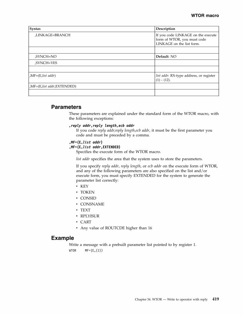
Syntax Description
,LINKAGE=BRANCH If you code LINKAGE on the executeform of WTOR, you must codeLINKAGE on the list form.
,SYNCH=NO Default: NO
,SYNCH=YES
,MF=(E,list addr) list addr: RX-type address, or register(1) - (12).
,MF=(E,list addr,EXTENDED)
ParametersThese parameters are explained under the standard form of the WTOR macro, withthe following exceptions:
,reply addr,reply length,ecb addrIf you code reply addr,reply length,ecb addr, it must be the first parameter youcode and must be preceded by a comma.
,MF=(E,list addr),MF=(E,list addr,EXTENDED)
Specifies the execute form of the WTOR macro.
list addr specifies the area that the system uses to store the parameters.
If you specify reply addr, reply length, or ecb addr on the execute form of WTOR,and any of the following parameters are also specified on the list and/orexecute form, you must specify EXTENDED for the system to generate theparameter list correctly:v KEYv TOKENv CONSIDv CONSNAMEv TEXTv RPLYISURv CARTv Any value of ROUTCDE higher than 16
ExampleWrite a message with a prebuilt parameter list pointed to by register 1.WTOR MF=(E,(1))
WTOR macro
Chapter 34. WTOR — Write to operator with reply 419

420 z/OS MVS Authorized Assembler Services Reference SET-WTO

Appendix. Accessibility
Accessible publications for this product are offered through IBM KnowledgeCenter (www.ibm.com/support/knowledgecenter/SSLTBW/welcome).
If you experience difficulty with the accessibility of any z/OS information, send adetailed message to the Contact z/OS web page (www.ibm.com/systems/z/os/zos/webqs.html) or use the following mailing address.
IBM CorporationAttention: MHVRCFS Reader CommentsDepartment H6MA, Building 7072455 South RoadPoughkeepsie, NY 12601-5400United States
Accessibility features
Accessibility features help users who have physical disabilities such as restrictedmobility or limited vision use software products successfully. The accessibilityfeatures in z/OS can help users do the following tasks:v Run assistive technology such as screen readers and screen magnifier software.v Operate specific or equivalent features by using the keyboard.v Customize display attributes such as color, contrast, and font size.
Consult assistive technologiesAssistive technology products such as screen readers function with the userinterfaces found in z/OS. Consult the product information for the specific assistivetechnology product that is used to access z/OS interfaces.
Keyboard navigation of the user interfaceYou can access z/OS user interfaces with TSO/E or ISPF. The followinginformation describes how to use TSO/E and ISPF, including the use of keyboardshortcuts and function keys (PF keys). Each guide includes the default settings forthe PF keys.v z/OS TSO/E Primer
v z/OS TSO/E User's Guide
v z/OS ISPF User's Guide Vol I
Dotted decimal syntax diagramsSyntax diagrams are provided in dotted decimal format for users who access IBMKnowledge Center with a screen reader. In dotted decimal format, each syntaxelement is written on a separate line. If two or more syntax elements are alwayspresent together (or always absent together), they can appear on the same linebecause they are considered a single compound syntax element.
Each line starts with a dotted decimal number; for example, 3 or 3.1 or 3.1.1. Tohear these numbers correctly, make sure that the screen reader is set to read out
© Copyright IBM Corp. 1988, 2017 421
punctuation. All the syntax elements that have the same dotted decimal number(for example, all the syntax elements that have the number 3.1) are mutuallyexclusive alternatives. If you hear the lines 3.1 USERID and 3.1 SYSTEMID, yoursyntax can include either USERID or SYSTEMID, but not both.
The dotted decimal numbering level denotes the level of nesting. For example, if asyntax element with dotted decimal number 3 is followed by a series of syntaxelements with dotted decimal number 3.1, all the syntax elements numbered 3.1are subordinate to the syntax element numbered 3.
Certain words and symbols are used next to the dotted decimal numbers to addinformation about the syntax elements. Occasionally, these words and symbolsmight occur at the beginning of the element itself. For ease of identification, if theword or symbol is a part of the syntax element, it is preceded by the backslash (\)character. The * symbol is placed next to a dotted decimal number to indicate thatthe syntax element repeats. For example, syntax element *FILE with dotted decimalnumber 3 is given the format 3 \* FILE. Format 3* FILE indicates that syntaxelement FILE repeats. Format 3* \* FILE indicates that syntax element * FILErepeats.
Characters such as commas, which are used to separate a string of syntaxelements, are shown in the syntax just before the items they separate. Thesecharacters can appear on the same line as each item, or on a separate line with thesame dotted decimal number as the relevant items. The line can also show anothersymbol to provide information about the syntax elements. For example, the lines5.1*, 5.1 LASTRUN, and 5.1 DELETE mean that if you use more than one of theLASTRUN and DELETE syntax elements, the elements must be separated by a comma.If no separator is given, assume that you use a blank to separate each syntaxelement.
If a syntax element is preceded by the % symbol, it indicates a reference that isdefined elsewhere. The string that follows the % symbol is the name of a syntaxfragment rather than a literal. For example, the line 2.1 %OP1 means that you mustrefer to separate syntax fragment OP1.
The following symbols are used next to the dotted decimal numbers.
? indicates an optional syntax elementThe question mark (?) symbol indicates an optional syntax element. A dotteddecimal number followed by the question mark symbol (?) indicates that allthe syntax elements with a corresponding dotted decimal number, and anysubordinate syntax elements, are optional. If there is only one syntax elementwith a dotted decimal number, the ? symbol is displayed on the same line asthe syntax element, (for example 5? NOTIFY). If there is more than one syntaxelement with a dotted decimal number, the ? symbol is displayed on a line byitself, followed by the syntax elements that are optional. For example, if youhear the lines 5 ?, 5 NOTIFY, and 5 UPDATE, you know that the syntax elementsNOTIFY and UPDATE are optional. That is, you can choose one or none of them.The ? symbol is equivalent to a bypass line in a railroad diagram.
! indicates a default syntax elementThe exclamation mark (!) symbol indicates a default syntax element. A dotteddecimal number followed by the ! symbol and a syntax element indicate thatthe syntax element is the default option for all syntax elements that share thesame dotted decimal number. Only one of the syntax elements that share thedotted decimal number can specify the ! symbol. For example, if you hear thelines 2? FILE, 2.1! (KEEP), and 2.1 (DELETE), you know that (KEEP) is the
422 z/OS MVS Authorized Assembler Services Reference SET-WTO

default option for the FILE keyword. In the example, if you include the FILEkeyword, but do not specify an option, the default option KEEP is applied. Adefault option also applies to the next higher dotted decimal number. In thisexample, if the FILE keyword is omitted, the default FILE(KEEP) is used.However, if you hear the lines 2? FILE, 2.1, 2.1.1! (KEEP), and 2.1.1(DELETE), the default option KEEP applies only to the next higher dotteddecimal number, 2.1 (which does not have an associated keyword), and doesnot apply to 2? FILE. Nothing is used if the keyword FILE is omitted.
* indicates an optional syntax element that is repeatableThe asterisk or glyph (*) symbol indicates a syntax element that can berepeated zero or more times. A dotted decimal number followed by the *symbol indicates that this syntax element can be used zero or more times; thatis, it is optional and can be repeated. For example, if you hear the line 5.1*data area, you know that you can include one data area, more than one dataarea, or no data area. If you hear the lines 3* , 3 HOST, 3 STATE, you knowthat you can include HOST, STATE, both together, or nothing.
Notes:
1. If a dotted decimal number has an asterisk (*) next to it and there is onlyone item with that dotted decimal number, you can repeat that same itemmore than once.
2. If a dotted decimal number has an asterisk next to it and several itemshave that dotted decimal number, you can use more than one item from thelist, but you cannot use the items more than once each. In the previousexample, you can write HOST STATE, but you cannot write HOST HOST.
3. The * symbol is equivalent to a loopback line in a railroad syntax diagram.
+ indicates a syntax element that must be includedThe plus (+) symbol indicates a syntax element that must be included at leastonce. A dotted decimal number followed by the + symbol indicates that thesyntax element must be included one or more times. That is, it must beincluded at least once and can be repeated. For example, if you hear the line6.1+ data area, you must include at least one data area. If you hear the lines2+, 2 HOST, and 2 STATE, you know that you must include HOST, STATE, orboth. Similar to the * symbol, the + symbol can repeat a particular item if it isthe only item with that dotted decimal number. The + symbol, like the *symbol, is equivalent to a loopback line in a railroad syntax diagram.
Appendix. Accessibility 423

424 z/OS MVS Authorized Assembler Services Reference SET-WTO

Notices
This information was developed for products and services that are offered in theUSA or elsewhere.
IBM may not offer the products, services, or features discussed in this document inother countries. Consult your local IBM representative for information on theproducts and services currently available in your area. Any reference to an IBMproduct, program, or service is not intended to state or imply that only that IBMproduct, program, or service may be used. Any functionally equivalent product,program, or service that does not infringe any IBM intellectual property right maybe used instead. However, it is the user's responsibility to evaluate and verify theoperation of any non-IBM product, program, or service.
IBM may have patents or pending patent applications covering subject matterdescribed in this document. The furnishing of this document does not grant youany license to these patents. You can send license inquiries, in writing, to:
IBM Director of LicensingIBM CorporationNorth Castle Drive, MD-NC119Armonk, NY 10504-1785United States of America
For license inquiries regarding double-byte character set (DBCS) information,contact the IBM Intellectual Property Department in your country or sendinquiries, in writing, to:
Intellectual Property LicensingLegal and Intellectual Property LawIBM Japan Ltd.19-21, Nihonbashi-Hakozakicho, Chuo-kuTokyo 103-8510, Japan
The following paragraph does not apply to the United Kingdom or any othercountry where such provisions are inconsistent with local law:INTERNATIONAL BUSINESS MACHINES CORPORATION PROVIDES THISPUBLICATION "AS IS" WITHOUT WARRANTY OF ANY KIND, EITHEREXPRESS OR IMPLIED, INCLUDING, BUT NOT LIMITED TO, THE IMPLIEDWARRANTIES OF NON-INFRINGEMENT, MERCHANTABILITY OR FITNESSFOR A PARTICULAR PURPOSE. Some states do not allow disclaimer of express orimplied warranties in certain transactions, therefore, this statement may not applyto you.
This information could include technical inaccuracies or typographical errors.Changes are periodically made to the information herein; these changes will beincorporated in new editions of the publication. IBM may make improvementsand/or changes in the product(s) and/or the program(s) described in thispublication at any time without notice.
© Copyright IBM Corp. 1988, 2017 425

This information could include missing, incorrect, or broken hyperlinks.Hyperlinks are maintained in only the HTML plug-in output for the KnowledgeCenters. Use of hyperlinks in other output formats of this information is at yourown risk.
Any references in this information to non-IBM websites are provided forconvenience only and do not in any manner serve as an endorsement of thosewebsites. The materials at those websites are not part of the materials for this IBMproduct and use of those websites is at your own risk.
IBM may use or distribute any of the information you supply in any way itbelieves appropriate without incurring any obligation to you.
Licensees of this program who wish to have information about it for the purposeof enabling: (i) the exchange of information between independently createdprograms and other programs (including this one) and (ii) the mutual use of theinformation which has been exchanged, should contact:
IBM CorporationSite Counsel2455 South RoadPoughkeepsie, NY 12601-5400USA
Such information may be available, subject to appropriate terms and conditions,including in some cases, payment of a fee.
The licensed program described in this document and all licensed materialavailable for it are provided by IBM under terms of the IBM Customer Agreement,IBM International Program License Agreement or any equivalent agreementbetween us.
Any performance data contained herein was determined in a controlledenvironment. Therefore, the results obtained in other operating environments mayvary significantly. Some measurements may have been made on development-levelsystems and there is no guarantee that these measurements will be the same ongenerally available systems. Furthermore, some measurements may have beenestimated through extrapolation. Actual results may vary. Users of this documentshould verify the applicable data for their specific environment.
Information concerning non-IBM products was obtained from the suppliers ofthose products, their published announcements or other publicly available sources.IBM has not tested those products and cannot confirm the accuracy ofperformance, compatibility or any other claims related to non-IBM products.Questions on the capabilities of non-IBM products should be addressed to thesuppliers of those products.
All statements regarding IBM's future direction or intent are subject to change orwithdrawal without notice, and represent goals and objectives only.
This information contains examples of data and reports used in daily businessoperations. To illustrate them as completely as possible, the examples include thenames of individuals, companies, brands, and products. All of these names arefictitious and any similarity to the names and addresses used by an actual businessenterprise is entirely coincidental.
426 z/OS MVS Authorized Assembler Services Reference SET-WTO

COPYRIGHT LICENSE:
This information contains sample application programs in source language, whichillustrate programming techniques on various operating platforms. You may copy,modify, and distribute these sample programs in any form without payment toIBM, for the purposes of developing, using, marketing or distributing applicationprograms conforming to the application programming interface for the operatingplatform for which the sample programs are written. These examples have notbeen thoroughly tested under all conditions. IBM, therefore, cannot guarantee orimply reliability, serviceability, or function of these programs. The sampleprograms are provided "AS IS", without warranty of any kind. IBM shall not beliable for any damages arising out of your use of the sample programs.
Terms and conditions for product documentationPermissions for the use of these publications are granted subject to the followingterms and conditions.
Applicability
These terms and conditions are in addition to any terms of use for the IBMwebsite.
Personal use
You may reproduce these publications for your personal, noncommercial useprovided that all proprietary notices are preserved. You may not distribute, displayor make derivative work of these publications, or any portion thereof, without theexpress consent of IBM.
Commercial use
You may reproduce, distribute and display these publications solely within yourenterprise provided that all proprietary notices are preserved. You may not makederivative works of these publications, or reproduce, distribute or display thesepublications or any portion thereof outside your enterprise, without the expressconsent of IBM.
Rights
Except as expressly granted in this permission, no other permissions, licenses orrights are granted, either express or implied, to the publications or anyinformation, data, software or other intellectual property contained therein.
IBM reserves the right to withdraw the permissions granted herein whenever, in itsdiscretion, the use of the publications is detrimental to its interest or, asdetermined by IBM, the above instructions are not being properly followed.
You may not download, export or re-export this information except in fullcompliance with all applicable laws and regulations, including all United Statesexport laws and regulations.
IBM MAKES NO GUARANTEE ABOUT THE CONTENT OF THESEPUBLICATIONS. THE PUBLICATIONS ARE PROVIDED "AS-IS" AND WITHOUTWARRANTY OF ANY KIND, EITHER EXPRESSED OR IMPLIED, INCLUDINGBUT NOT LIMITED TO IMPLIED WARRANTIES OF MERCHANTABILITY,
Notices 427

NON-INFRINGEMENT, AND FITNESS FOR A PARTICULAR PURPOSE.
IBM Online Privacy StatementIBM Software products, including software as a service solutions, (“SoftwareOfferings”) may use cookies or other technologies to collect product usageinformation, to help improve the end user experience, to tailor interactions withthe end user, or for other purposes. In many cases no personally identifiableinformation is collected by the Software Offerings. Some of our Software Offeringscan help enable you to collect personally identifiable information. If this SoftwareOffering uses cookies to collect personally identifiable information, specificinformation about this offering’s use of cookies is set forth below.
Depending upon the configurations deployed, this Software Offering may usesession cookies that collect each user’s name, email address, phone number, orother personally identifiable information for purposes of enhanced user usabilityand single sign-on configuration. These cookies can be disabled, but disablingthem will also eliminate the functionality they enable.
If the configurations deployed for this Software Offering provide you as customerthe ability to collect personally identifiable information from end users via cookiesand other technologies, you should seek your own legal advice about any lawsapplicable to such data collection, including any requirements for notice andconsent.
For more information about the use of various technologies, including cookies, forthese purposes, see IBM’s Privacy Policy at ibm.com/privacy and IBM’s OnlinePrivacy Statement at ibm.com/privacy/details in the section entitled “Cookies,Web Beacons and Other Technologies,” and the “IBM Software Products andSoftware-as-a-Service Privacy Statement” at ibm.com/software/info/product-privacy.
Policy for unsupported hardwareVarious z/OS elements, such as DFSMS, JES2, JES3, and MVS, contain code thatsupports specific hardware servers or devices. In some cases, this device-relatedelement support remains in the product even after the hardware devices pass theirannounced End of Service date. z/OS may continue to service element code;however, it will not provide service related to unsupported hardware devices.Software problems related to these devices will not be accepted for service, andcurrent service activity will cease if a problem is determined to be associated without-of-support devices. In such cases, fixes will not be issued.
Minimum supported hardwareThe minimum supported hardware for z/OS releases identified in z/OSannouncements can subsequently change when service for particular servers ordevices is withdrawn. Likewise, the levels of other software products supported ona particular release of z/OS are subject to the service support lifecycle of thoseproducts. Therefore, z/OS and its product publications (for example, panels,samples, messages, and product documentation) can include references tohardware and software that is no longer supported.v For information about software support lifecycle, see: IBM Lifecycle Support for
z/OS (www.ibm.com/software/support/systemsz/lifecycle)
428 z/OS MVS Authorized Assembler Services Reference SET-WTO

v For information about currently-supported IBM hardware, contact your IBMrepresentative.
Programming interface informationThis information is intended to help the customer to code macros that are availableto authorized assembler language programs. This information documents intendedprogramming interfaces that allow the customer to write programs to obtainservices of z/OS.
TrademarksIBM, the IBM logo, and ibm.com are trademarks or registered trademarks ofInternational Business Machines Corp., registered in many jurisdictions worldwide.Other product and service names might be trademarks of IBM or other companies.A current list of IBM trademarks is available on the Web at Copyright andTrademark information (www.ibm.com/legal/copytrade.shtml).
Linux is a registered trademark of Linus Torvalds in the United States, othercountries, or both.
Microsoft, Windows, Windows NT, and the Windows logo are trademarks ofMicrosoft Corporation in the United States, other countries, or both.
UNIX is a registered trademark of The Open Group in the United States and othercountries.
Notices 429

430 z/OS MVS Authorized Assembler Services Reference SET-WTO

Index
Aaccessibility 421
contact IBM 421features 421
addressing mode and the services 2ALET qualification
of parameters 4AR () mode
description 3ASC (address space control) mode
defining 3assistive technologies 421authorization
testing caller 221
Ccallable service
coding 16caller
testing authorization 221coding the callable services 16coding the macros 13contact
z/OS 421continuation line 16control access to a serially reusable
resource 35CPU time
obtaining accumulated 225
Eevent
waiting for one or more 361
Ffeedback xviifunctional recovery routine
setting up 29
IIHATRBPL mapping macro 192IHATREPL mapping macro 193
Kkeyboard
navigation 421PF keys 421shortcut keys 421
Llog
writing 367
Mmacro
coding 13forms 12level
selecting 1sample 14selecting level 1user parameter, passing 4X-macros
using 11
Nnavigation
keyboard 421
Pparameter
setting return 47process
putting in process-must-completemode 107
process-must-complete mode 107
Qquery virtual server 207QVS 207
RRETRIEVE service
reason codes 171return codes 171
Ssending to IBM
reader comments xviiservice
ALET qualification 4summary 18
servicesaddressing mode 2ASC mode
defining 3using 1
SETFRR macro 29SETLOCK macro 35SETRP macro 47shortcut keys 421SJFREQ macro 57
RETRIEVE service 59, 63SWBTU_MERGE service 59, 67, 69TERMINATE service 60, 90VERIFY service 60, 76
SPIE macro 91SPOST macro 97SRB (service request block)
transferring control 219SRB status 99SRBSTAT macro 99SRBTIMER macro 103STATUS macro 107storage
obtaining and releasing 115STORAGE macro 115subtask
starting and stopping 107summary of changes
z/OS MVS Programming: AuthorizedAssembler Services ReferenceSET-WTO xix
Summary of changes xxSUSPEND macro for RBs 143, 145SUSPEND macro for SRBs 145SVC exit
type 6 233SVCUPDTE macro 151SWA manager
invoking in locate mode 161SWAREQ macro 161SWBTUREQ macro 167SYNCH and SYNCHX macros 177, 187synchronous exit
to a processing program 177SYSEVENT macro 187
TT6EXIT macro 233TCBTOKEN macro 211
description 211TCTL macro 219TESTAUTH macro 221time limit
establishing for system service 103TIMEUSED macro 225
UUCB (unit control block)
obtaining address 295pinning 307scanning 315unpinning 307
UCBINFO macro 235UCBLOOK macro 295UCBPIN macro 307UCBSCAN macro 315user interface
ISPF 421TSO/E 421
user parameterpassing 4
© Copyright IBM Corp. 1988, 2017 431

Vvector time
obtaining accumulated 225virtual storage
map 341obtaining private area region
size 357verifying allocation 349
VSMLIST macro 341VSMLOC macro 349VSMREGN macro 357
WWAIT macro 361WTL macro 367WTO macro 375WTOR macro 399
XX-macros
using 11
Zz/OS MVS Programming: Authorized
Assembler Services Reference SET-WTOsummary of changes xix
432 z/OS MVS Authorized Assembler Services Reference SET-WTO


IBM®
Product Number: 5650-ZOS
Printed in USA
SA23-1375-30