zimo: building cross-technology mimo to harmonize zigbee smog
TRANSCRIPT
ZIMO: Building Cross-Technology MIMO to HarmonizeZigBee Smog with WiFi Flash without Intervention
Yubo Yan1, Panlong Yang1,3, Xiang-Yang Li2,3, Yue Tao2, Lan Zhang3, Lizhao You4
1PLA University of Science and Technology, China2Department of Computer Science, Illinois Institute of Technology, USA
3School of Software and TNLIST, Tsinghua University, China4Department of Computer Science and Technology, Nanjing University, China
[email protected], [email protected], [email protected], [email protected],[email protected], [email protected]
ABSTRACTRecent studies show that WiFi interference has been a ma-jor problem for low power urban sensing technology ZigBeenetworks. Existing approaches for dealing with such inter-ferences often modify either the ZigBee nodes or WiFi nodes.However, massive deployment of ZigBee nodes and uncoop-erative WiFi users call for innovative cross-technology coex-istence without intervening legacy systems.In this work we investigate the WiFi and ZigBee coex-
istence when ZigBee is the interested signal. Mitigatingshort duration WiFi interference (called flash) in long du-ration ZigBee data (called smog) is challenging, especiallywhen we cannot modify the WiFi APs and the massivelydeployed sensor nodes. To address these challenges, we pro-pose ZIMO, a sink-based MIMO design for harmony coex-istence of ZigBee and WiFi networks with the goal of pro-tecting the ZigBee data packets. The key insight of ZIMOis to properly exploit opportunities resulted from differencesbetween WiFi and ZigBee, and bridge the gap between inter-ested data and cross technology signals. Also, extracting thechannel coefficient of WiFi and ZigBee will enhance other co-existence technologies such as TIMO [1]. We implement aprototype for ZIMO in GNURadio-USRP N200, and our ex-tensive evaluations under real wireless conditions show thatZIMO can improve up to 1.9× throughput for ZigBee net-work, with median gain of 1.5×, and 1.1× to 1.9× for WiFinetwork as byproduct in ZigBee signal recovery.
Categories and Subject DescriptorsC.2.1 [COMPUTER-COMMUNICATIONNETWORKS]: Network Architectureand Design—Wireless communication
General TermsDesign, Experimentation, Performance
Permission to make digital or hard copies of all or part of this work for personal orclassroom use is granted without fee provided that copies are not made or distributedfor profit or commercial advantage and that copies bear this notice and the full cita-tion on the first page. Copyrights for components of this work owned by others thanACM must be honored. Abstracting with credit is permitted. To copy otherwise, or re-publish, to post on servers or to redistribute to lists, requires prior specific permissionand/or a fee. Request permissions from [email protected]’13, September 30-October 4, Miami, FL, USA.Copyright 2013 ACM 978-1-4503-1999-7/13/09 ...$15.00.
KeywordsMIMO, Physical Layer, Sensor Networks
1. INTRODUCTIONUrban area wireless sensor networks are becoming vitally
important for nowadays“smart city”programs. These grandengineering work heavily depend on sensor nodes and effi-cient network connections for monitoring environment. Mostof the urban sensing systems are leveraging the COTS Zig-Bee, such as Urban sense [2], CitySee [3]. Unfortunately,in urban areas, WiFi interference is pervasive and possiblythe primary factor leading to ZigBee throughput degrada-tion [1, 4–7]. Meanwhile, it has been verified that the WiFinetwork performance can be affected by the ZigBee interfer-ence [8]. It is worth noting that, protecting ZigBee signaland extracting the interested data from the cross-technologynoise is not trivial. Previous studies [1, 8] indiscriminatelytake the ZigBee signal as cross-technology interference, espe-cially RF smog, which leaves a gap between WiFi and othercross-technologies for coexistence. Notably, ZigBee is similarto WiFi in sense of CSMA scheme, and apparently differentfrom RF technologies without communication functionality,such as microwave oven.
In summary, existing solutions can not reasonably work inurban sensing sensor networks. There are several specific re-quirements in building an efficient ZigBee system coexistingwith WiFi systems. Foremost, there should be no modi-fication or intervention on the end nodes in either ZigBeeor WiFi networks. For urban sensing, modifying the soft-ware and/or hardware on the sensor nodes is difficult andexpensive. Furthermore, WiFi AP holders are reluctant tomake any changes even when ZigBee nodes interfere them.Meanwhile, it is expected that the performance degradationcaused by coexistence should be minimized. In our case,ZigBee is interested signal, but the WiFi transmission is ex-pected to be pervasive. This is the key idea of harmonycoexistence, where two systems can share the conflicted net-work resource, without harming each other.
Fully considering these design requirements, we proposeZIMO, a cross-technology MIMO sink design to harmonizethe coexistence of ZigBee andWiFi networks. Different fromprevious studies, in our design, the sink node performs thecoexistence work, and the end nodes in WiFi and ZigBeenetworks need not do any further modification. Adding amodified sink is relatively easy and more affordable than re-
Receiver (1)
Transmitter (1)
Transmitter (2, 3)
Receiver (3)Receiver (2)
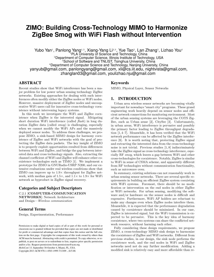
Figure 1: Indoor layout of the experiment.
programming all the deployed sensor nodes. In ZIMO, weleverage a 2-antenna MIMO system for WiFi and ZigBee in-terference resolution. To the best of our knowledge, ZIMOis the first implemented working system meeting the afore-mentioned requirements. There are several challenges thatneed to be addressed carefully in designing and implement-ing ZIMO, which are summarized as follows.First, unpredictable and uncooperative WiFi interference
will incur different interference patterns. WhenWiFi pream-ble is clear, the WiFi signal needs to be nullified first forZigBee signal decoding. Inevitably, the WiFi channel coef-ficient estimation will suffer unfavorable distortions due toZigBee interference, and will incur unsatisfiable ZigBee sig-nal recovery.Second, when WiFi flash is drowned in ZigBee smog, sig-
nals in two technologies are cross-affected in both time andfrequency domain. For WiFi signal, there is no clear ref-erence for accurate channel coefficient estimation. Evenworse, considering the low-power ZigBee signal, more ac-curate and thorough interference cancelation for WiFi sig-nal is needed. Thus, the CFO (Carrier Frequency Offset)estimation across receiving symbols are not negligible com-paring with conventional interference cancelation and align-ment schemes [9]. For ZigBee signal, the channel coefficientestimation should be carefully considered as the frequencyoffset can be possibly up to 200 KHz [10], which means accu-rate and fast enough synchronization should be done withinZigBee preamble time.ZIMO addresses these challenges with two innovative tech-
niques. For the first challenge, a blind recovery method forWiFi channel coefficient is presented, based on interpola-tion that exploits the continuous and steady feature in fre-quency domain. With this advantage, the second challengefor WiFi signal is addressed by a linear regression model usedfor fine frequency offset compensation across WiFi symbols.Also for ZigBee signal, an innovative ZigBee channel coeffi-cient estimation method is proposed, where large frequencyoffset is estimated and compensated through modulation-independent approach.In summary, our main contributions are as follows.We propose ZIMO, a sink based MIMO design for har-
mony coexistence of WiFi and ZigBee by protecting the Zig-Bee data from being interfered. Our design need not modifyand intervene on WiFi APs or ZigBee nodes. A key insightof the work is to properly handle the relationship betweenWiFi and ZigBee where opportunities in time, spectral andpower domain due to cross-technology can be leveraged. The
100
101
102
103
104
101 102 103 104
Fre
quen
cy (
Tim
es)
Duration (µs)
Channel 1Channel 6
Channel 11
(a) Duration of Corrupted
100
101
102
103
104
101 102 103 104 105 106
Fre
quen
cy (
Tim
es)
Interval (µs)
Channel 1Channel 6
Channel 11
(b) Interval between Corrupted
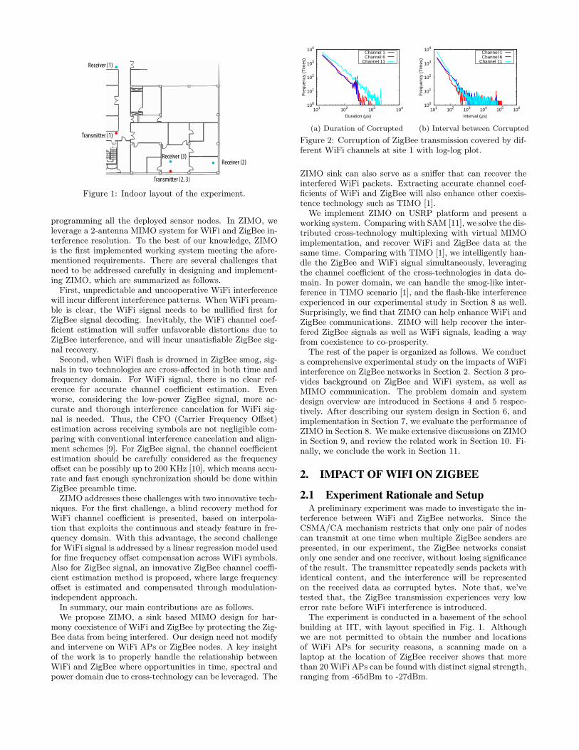
Figure 2: Corruption of ZigBee transmission covered by dif-ferent WiFi channels at site 1 with log-log plot.
ZIMO sink can also serve as a sniffer that can recover theinterfered WiFi packets. Extracting accurate channel coef-ficients of WiFi and ZigBee will also enhance other coexis-tence technology such as TIMO [1].
We implement ZIMO on USRP platform and present aworking system. Comparing with SAM [11], we solve the dis-tributed cross-technology multiplexing with virtual MIMOimplementation, and recover WiFi and ZigBee data at thesame time. Comparing with TIMO [1], we intelligently han-dle the ZigBee and WiFi signal simultaneously, leveragingthe channel coefficient of the cross-technologies in data do-main. In power domain, we can handle the smog-like inter-ference in TIMO scenario [1], and the flash-like interferenceexperienced in our experimental study in Section 8 as well.Surprisingly, we find that ZIMO can help enhance WiFi andZigBee communications. ZIMO will help recover the inter-fered ZigBee signals as well as WiFi signals, leading a wayfrom coexistence to co-prosperity.
The rest of the paper is organized as follows. We conducta comprehensive experimental study on the impacts of WiFiinterference on ZigBee networks in Section 2. Section 3 pro-vides background on ZigBee and WiFi system, as well asMIMO communication. The problem domain and systemdesign overview are introduced in Sections 4 and 5 respec-tively. After describing our system design in Section 6, andimplementation in Section 7, we evaluate the performance ofZIMO in Section 8. We make extensive discussions on ZIMOin Section 9, and review the related work in Section 10. Fi-nally, we conclude the work in Section 11.
2. IMPACT OF WIFI ON ZIGBEE
2.1 Experiment Rationale and SetupA preliminary experiment was made to investigate the in-
terference between WiFi and ZigBee networks. Since theCSMA/CA mechanism restricts that only one pair of nodescan transmit at one time when multiple ZigBee senders arepresented, in our experiment, the ZigBee networks consistonly one sender and one receiver, without losing significanceof the result. The transmitter repeatedly sends packets withidentical content, and the interference will be representedon the received data as corrupted bytes. Note that, we’vetested that, the ZigBee transmission experiences very lowerror rate before WiFi interference is introduced.
The experiment is conducted in a basement of the schoolbuilding at IIT, with layout specified in Fig. 1. Althoughwe are not permitted to obtain the number and locationsof WiFi APs for security reasons, a scanning made on alaptop at the location of ZigBee receiver shows that morethan 20WiFi APs can be found with distinct signal strength,ranging from -65dBm to -27dBm.
100
101
102
103
104
105
101 102 103 104
Fre
quen
cy (
Tim
es)
Length (Byte)
(a) Length statistics
10-1
100
101
102
103
100 101 102 103 104 105 106 107 108
Fre
quen
cy (
Tim
es)
Interval (µs)
(b) Interval statistics
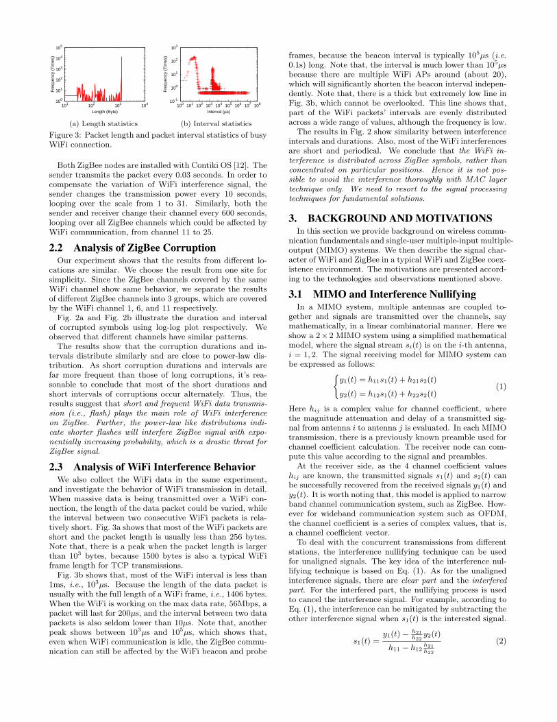
Figure 3: Packet length and packet interval statistics of busyWiFi connection.
Both ZigBee nodes are installed with Contiki OS [12]. Thesender transmits the packet every 0.03 seconds. In order tocompensate the variation of WiFi interference signal, thesender changes the transmission power every 10 seconds,looping over the scale from 1 to 31. Similarly, both thesender and receiver change their channel every 600 seconds,looping over all ZigBee channels which could be affected byWiFi communication, from channel 11 to 25.
2.2 Analysis of ZigBee CorruptionOur experiment shows that the results from different lo-
cations are similar. We choose the result from one site forsimplicity. Since the ZigBee channels covered by the sameWiFi channel show same behavior, we separate the resultsof different ZigBee channels into 3 groups, which are coveredby the WiFi channel 1, 6, and 11 respectively.Fig. 2a and Fig. 2b illustrate the duration and interval
of corrupted symbols using log-log plot respectively. Weobserved that different channels have similar patterns.The results show that the corruption durations and in-
tervals distribute similarly and are close to power-law dis-tribution. As short corruption durations and intervals arefar more frequent than those of long corruptions, it’s rea-sonable to conclude that most of the short durations andshort intervals of corruptions occur alternately. Thus, theresults suggest that short and frequent WiFi data transmis-sion (i.e., flash) plays the main role of WiFi interferenceon ZigBee. Further, the power-law like distributions indi-cate shorter flashes will interfere ZigBee signal with expo-nentially increasing probability, which is a drastic threat forZigBee signal.
2.3 Analysis of WiFi Interference BehaviorWe also collect the WiFi data in the same experiment,
and investigate the behavior of WiFi transmission in detail.When massive data is being transmitted over a WiFi con-nection, the length of the data packet could be varied, whilethe interval between two consecutive WiFi packets is rela-tively short. Fig. 3a shows that most of the WiFi packets areshort and the packet length is usually less than 256 bytes.Note that, there is a peak when the packet length is largerthan 103 bytes, because 1500 bytes is also a typical WiFiframe length for TCP transmissions.Fig. 3b shows that, most of the WiFi interval is less than
1ms, i.e., 103µs. Because the length of the data packet isusually with the full length of a WiFi frame, i.e., 1406 bytes.When the WiFi is working on the max data rate, 56Mbps, apacket will last for 200µs, and the interval between two datapackets is also seldom lower than 10µs. Note that, anotherpeak shows between 103µs and 105µs, which shows that,even when WiFi communication is idle, the ZigBee commu-nication can still be affected by the WiFi beacon and probe
frames, because the beacon interval is typically 105µs (i.e.0.1s) long. Note that, the interval is much lower than 105µsbecause there are multiple WiFi APs around (about 20),which will significantly shorten the beacon interval indepen-dently. Note that, there is a thick but extremely low line inFig. 3b, which cannot be overlooked. This line shows that,part of the WiFi packets’ intervals are evenly distributedacross a wide range of values, although the frequency is low.
The results in Fig. 2 show similarity between interferenceintervals and durations. Also, most of the WiFi interferencesare short and periodical. We conclude that the WiFi in-terference is distributed across ZigBee symbols, rather thanconcentrated on particular positions. Hence it is not pos-sible to avoid the interference thoroughly with MAC layertechnique only. We need to resort to the signal processingtechniques for fundamental solutions.
3. BACKGROUND AND MOTIVATIONSIn this section we provide background on wireless commu-
nication fundamentals and single-user multiple-input multiple-output (MIMO) systems. We then describe the signal char-acter of WiFi and ZigBee in a typical WiFi and ZigBee coex-istence environment. The motivations are presented accord-ing to the technologies and observations mentioned above.
3.1 MIMO and Interference NullifyingIn a MIMO system, multiple antennas are coupled to-
gether and signals are transmitted over the channels, saymathematically, in a linear combinatorial manner. Here weshow a 2× 2 MIMO system using a simplified mathematicalmodel, where the signal stream si(t) is on the i-th antenna,i = 1, 2. The signal receiving model for MIMO system canbe expressed as follows:{
y1(t) = h11s1(t) + h21s2(t)
y2(t) = h12s1(t) + h22s2(t)(1)
Here hij is a complex value for channel coefficient, wherethe magnitude attenuation and delay of a transmitted sig-nal from antenna i to antenna j is evaluated. In each MIMOtransmission, there is a previously known preamble used forchannel coefficient calculation. The receiver node can com-pute this value according to the signal and preambles.
At the receiver side, as the 4 channel coefficient valueshij are known, the transmitted signals s1(t) and s2(t) canbe successfully recovered from the received signals y1(t) andy2(t). It is worth noting that, this model is applied to narrowband channel communication system, such as ZigBee. How-ever for wideband communication system such as OFDM,the channel coefficient is a series of complex values, that is,a channel coefficient vector.
To deal with the concurrent transmissions from differentstations, the interference nullifying technique can be usedfor unaligned signals. The key idea of the interference nul-lifying technique is based on Eq. (1). As for the unalignedinterference signals, there are clear part and the interferedpart. For the interfered part, the nullifying process is usedto cancel the interference signal. For example, according toEq. (1), the interference can be mitigated by subtracting theother interference signal when s1(t) is the interested signal.
s1(t) =y1(t)− h21
h22y2(t)
h11 − h12h21h22
(2)
3.2 Preliminary Observations for IEEE 802.11and 802.15.4 Signals
Time (ms)
Fre
quen
cy (
GH
z)
0.2 0.4 0.6 0.8 1
2.425
2.427
2.430
2.432
2.434
2.437
2.439
−30dB
−25dB
−20dB
−15dB
−10dB
−5dB
0dB
ZigBee
WiFi
(a) Spectral and time domain
Time (ms)
Fre
quen
cy (
GH
z)
0.2 0.4 0.6 0.8 1
2.425
2.427
2.430
2.432
2.434
2.437
2.439
−30dB
−25dB
−20dB
−15dB
−10dB
−5dB
0dB
ZigBee
WiFi Signal after Cancelation
(b) After WiFi Cancelation
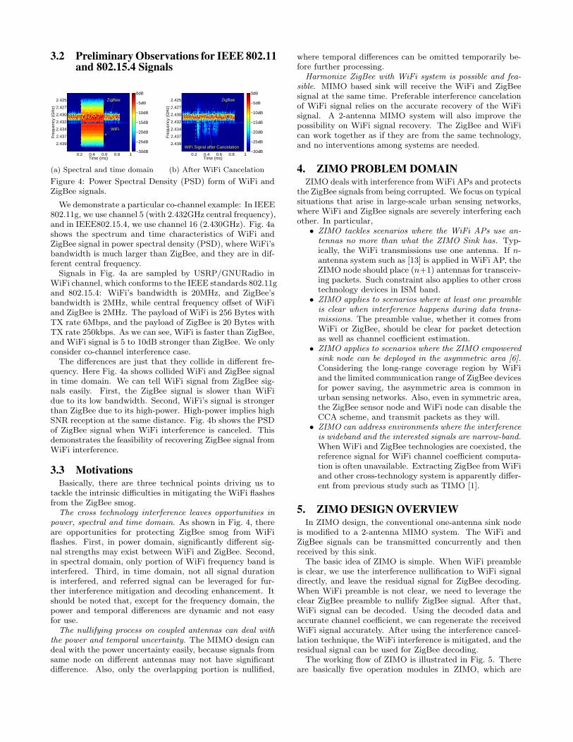
Figure 4: Power Spectral Density (PSD) form of WiFi andZigBee signals.
We demonstrate a particular co-channel example: In IEEE802.11g, we use channel 5 (with 2.432GHz central frequency),and in IEEE802.15.4, we use channel 16 (2.430GHz). Fig. 4ashows the spectrum and time characteristics of WiFi andZigBee signal in power spectral density (PSD), where WiFi’sbandwidth is much larger than ZigBee, and they are in dif-ferent central frequency.Signals in Fig. 4a are sampled by USRP/GNURadio in
WiFi channel, which conforms to the IEEE standards 802.11gand 802.15.4: WiFi’s bandwidth is 20MHz, and ZigBee’sbandwidth is 2MHz, while central frequency offset of WiFiand ZigBee is 2MHz. The payload of WiFi is 256 Bytes withTX rate 6Mbps, and the payload of ZigBee is 20 Bytes withTX rate 250kbps. As we can see, WiFi is faster than ZigBee,and WiFi signal is 5 to 10dB stronger than ZigBee. We onlyconsider co-channel interference case.The differences are just that they collide in different fre-
quency. Here Fig. 4a shows collided WiFi and ZigBee signalin time domain. We can tell WiFi signal from ZigBee sig-nals easily. First, the ZigBee signal is slower than WiFidue to its low bandwidth. Second, WiFi’s signal is strongerthan ZigBee due to its high-power. High-power implies highSNR reception at the same distance. Fig. 4b shows the PSDof ZigBee signal when WiFi interference is canceled. Thisdemonstrates the feasibility of recovering ZigBee signal fromWiFi interference.
3.3 MotivationsBasically, there are three technical points driving us to
tackle the intrinsic difficulties in mitigating the WiFi flashesfrom the ZigBee smog.The cross technology interference leaves opportunities in
power, spectral and time domain. As shown in Fig. 4, thereare opportunities for protecting ZigBee smog from WiFiflashes. First, in power domain, significantly different sig-nal strengths may exist between WiFi and ZigBee. Second,in spectral domain, only portion of WiFi frequency band isinterfered. Third, in time domain, not all signal durationis interfered, and referred signal can be leveraged for fur-ther interference mitigation and decoding enhancement. Itshould be noted that, except for the frequency domain, thepower and temporal differences are dynamic and not easyfor use.The nullifying process on coupled antennas can deal with
the power and temporal uncertainty. The MIMO design candeal with the power uncertainty easily, because signals fromsame node on different antennas may not have significantdifference. Also, only the overlapping portion is nullified,
where temporal differences can be omitted temporarily be-fore further processing.
Harmonize ZigBee with WiFi system is possible and fea-sible. MIMO based sink will receive the WiFi and ZigBeesignal at the same time. Preferable interference cancelationof WiFi signal relies on the accurate recovery of the WiFisignal. A 2-antenna MIMO system will also improve thepossibility on WiFi signal recovery. The ZigBee and WiFican work together as if they are from the same technology,and no interventions among systems are needed.
4. ZIMO PROBLEM DOMAINZIMO deals with interference fromWiFi APs and protects
the ZigBee signals from being corrupted. We focus on typicalsituations that arise in large-scale urban sensing networks,where WiFi and ZigBee signals are severely interfering eachother. In particular,
• ZIMO tackles scenarios where the WiFi APs use an-tennas no more than what the ZIMO Sink has. Typ-ically, the WiFi transmissions use one antenna. If n-antenna system such as [13] is applied in WiFi AP, theZIMO node should place (n+1) antennas for transceiv-ing packets. Such constraint also applies to other crosstechnology devices in ISM band.
• ZIMO applies to scenarios where at least one preambleis clear when interference happens during data trans-missions. The preamble value, whether it comes fromWiFi or ZigBee, should be clear for packet detectionas well as channel coefficient estimation.
• ZIMO applies to scenarios where the ZIMO empoweredsink node can be deployed in the asymmetric area [6].Considering the long-range coverage region by WiFiand the limited communication range of ZigBee devicesfor power saving, the asymmetric area is common inurban sensing networks. Also, even in symmetric area,the ZigBee sensor node and WiFi node can disable theCCA scheme, and transmit packets as they will.
• ZIMO can address environments where the interferenceis wideband and the interested signals are narrow-band.When WiFi and ZigBee technologies are coexisted, thereference signal for WiFi channel coefficient computa-tion is often unavailable. Extracting ZigBee fromWiFiand other cross-technology system is apparently differ-ent from previous study such as TIMO [1].
5. ZIMO DESIGN OVERVIEWIn ZIMO design, the conventional one-antenna sink node
is modified to a 2-antenna MIMO system. The WiFi andZigBee signals can be transmitted concurrently and thenreceived by this sink.
The basic idea of ZIMO is simple. When WiFi preambleis clear, we use the interference nullification to WiFi signaldirectly, and leave the residual signal for ZigBee decoding.When WiFi preamble is not clear, we need to leverage theclear ZigBee preamble to nullify ZigBee signal. After that,WiFi signal can be decoded. Using the decoded data andaccurate channel coefficient, we can regenerate the receivedWiFi signal accurately. After using the interference cancel-lation technique, the WiFi interference is mitigated, and theresidual signal can be used for ZigBee decoding.
The working flow of ZIMO is illustrated in Fig. 5. Thereare basically five operation modules in ZIMO, which are
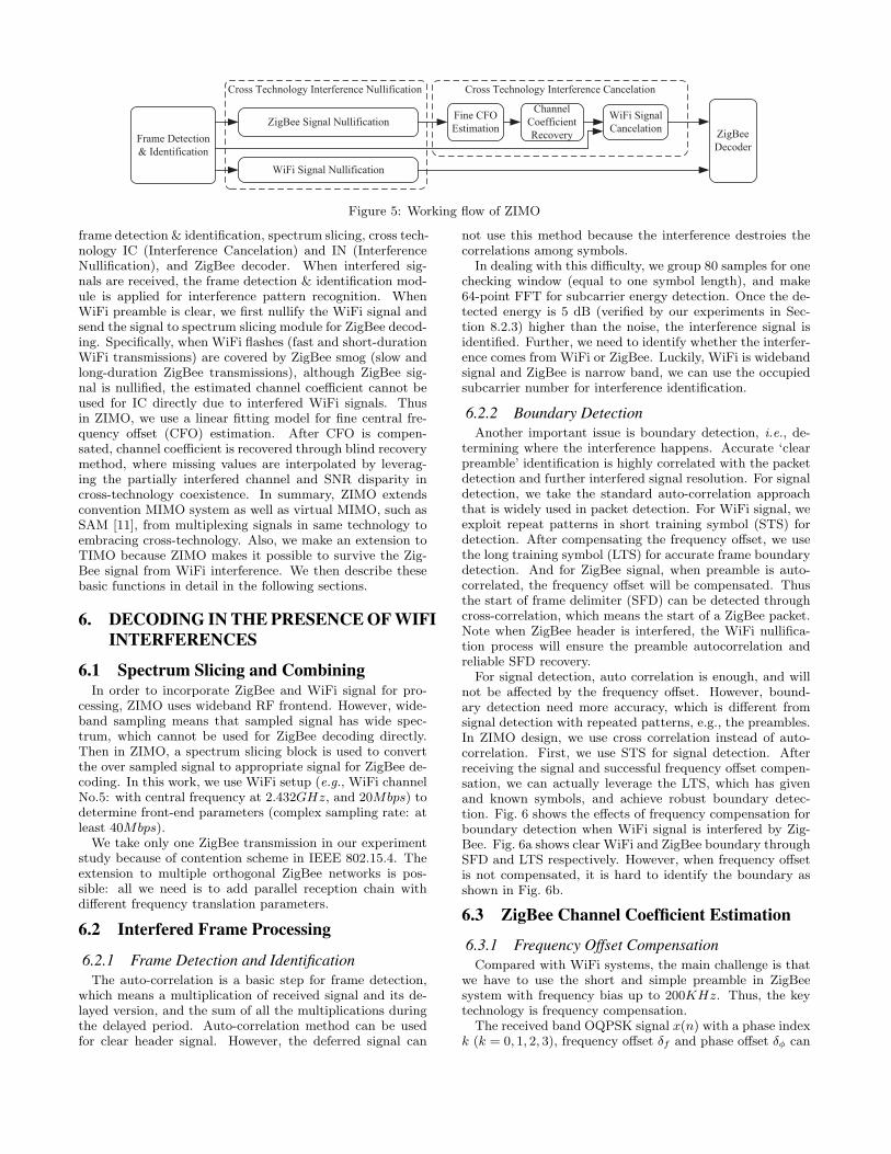
Frame Detection
& Identification
ZigBee Signal NullificationZigBee
Decoder
WiFi Signal
Cancelation
WiFi Signal Nullification
Cross Technology Interference Nullification Cross Technology Interference Cancelation
Channel
Coefficient
Recovery
Fine CFO
Estimation
Figure 5: Working flow of ZIMO
frame detection & identification, spectrum slicing, cross tech-nology IC (Interference Cancelation) and IN (InterferenceNullification), and ZigBee decoder. When interfered sig-nals are received, the frame detection & identification mod-ule is applied for interference pattern recognition. WhenWiFi preamble is clear, we first nullify the WiFi signal andsend the signal to spectrum slicing module for ZigBee decod-ing. Specifically, when WiFi flashes (fast and short-durationWiFi transmissions) are covered by ZigBee smog (slow andlong-duration ZigBee transmissions), although ZigBee sig-nal is nullified, the estimated channel coefficient cannot beused for IC directly due to interfered WiFi signals. Thusin ZIMO, we use a linear fitting model for fine central fre-quency offset (CFO) estimation. After CFO is compen-sated, channel coefficient is recovered through blind recoverymethod, where missing values are interpolated by leverag-ing the partially interfered channel and SNR disparity incross-technology coexistence. In summary, ZIMO extendsconvention MIMO system as well as virtual MIMO, such asSAM [11], from multiplexing signals in same technology toembracing cross-technology. Also, we make an extension toTIMO because ZIMO makes it possible to survive the Zig-Bee signal from WiFi interference. We then describe thesebasic functions in detail in the following sections.
6. DECODING IN THE PRESENCE OF WIFIINTERFERENCES
6.1 Spectrum Slicing and CombiningIn order to incorporate ZigBee and WiFi signal for pro-
cessing, ZIMO uses wideband RF frontend. However, wide-band sampling means that sampled signal has wide spec-trum, which cannot be used for ZigBee decoding directly.Then in ZIMO, a spectrum slicing block is used to convertthe over sampled signal to appropriate signal for ZigBee de-coding. In this work, we use WiFi setup (e.g., WiFi channelNo.5: with central frequency at 2.432GHz, and 20Mbps) todetermine front-end parameters (complex sampling rate: atleast 40Mbps).We take only one ZigBee transmission in our experiment
study because of contention scheme in IEEE 802.15.4. Theextension to multiple orthogonal ZigBee networks is pos-sible: all we need is to add parallel reception chain withdifferent frequency translation parameters.
6.2 Interfered Frame Processing
6.2.1 Frame Detection and IdentificationThe auto-correlation is a basic step for frame detection,
which means a multiplication of received signal and its de-layed version, and the sum of all the multiplications duringthe delayed period. Auto-correlation method can be usedfor clear header signal. However, the deferred signal can
not use this method because the interference destroies thecorrelations among symbols.
In dealing with this difficulty, we group 80 samples for onechecking window (equal to one symbol length), and make64-point FFT for subcarrier energy detection. Once the de-tected energy is 5 dB (verified by our experiments in Sec-tion 8.2.3) higher than the noise, the interference signal isidentified. Further, we need to identify whether the interfer-ence comes from WiFi or ZigBee. Luckily, WiFi is widebandsignal and ZigBee is narrow band, we can use the occupiedsubcarrier number for interference identification.
6.2.2 Boundary DetectionAnother important issue is boundary detection, i.e., de-
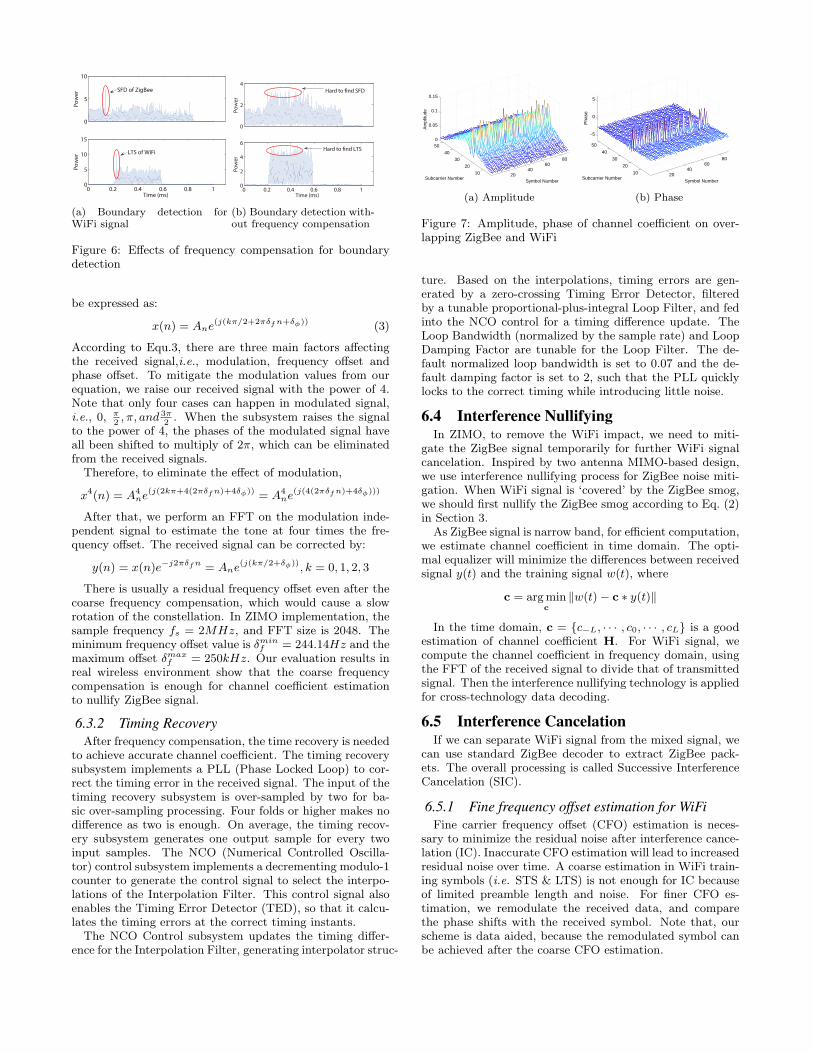
termining where the interference happens. Accurate ‘clearpreamble’ identification is highly correlated with the packetdetection and further interfered signal resolution. For signaldetection, we take the standard auto-correlation approachthat is widely used in packet detection. For WiFi signal, weexploit repeat patterns in short training symbol (STS) fordetection. After compensating the frequency offset, we usethe long training symbol (LTS) for accurate frame boundarydetection. And for ZigBee signal, when preamble is auto-correlated, the frequency offset will be compensated. Thusthe start of frame delimiter (SFD) can be detected throughcross-correlation, which means the start of a ZigBee packet.Note when ZigBee header is interfered, the WiFi nullifica-tion process will ensure the preamble autocorrelation andreliable SFD recovery.
For signal detection, auto correlation is enough, and willnot be affected by the frequency offset. However, bound-ary detection need more accuracy, which is different fromsignal detection with repeated patterns, e.g., the preambles.In ZIMO design, we use cross correlation instead of auto-correlation. First, we use STS for signal detection. Afterreceiving the signal and successful frequency offset compen-sation, we can actually leverage the LTS, which has givenand known symbols, and achieve robust boundary detec-tion. Fig. 6 shows the effects of frequency compensation forboundary detection when WiFi signal is interfered by Zig-Bee. Fig. 6a shows clear WiFi and ZigBee boundary throughSFD and LTS respectively. However, when frequency offsetis not compensated, it is hard to identify the boundary asshown in Fig. 6b.
6.3 ZigBee Channel Coefficient Estimation
6.3.1 Frequency Offset CompensationCompared with WiFi systems, the main challenge is that
we have to use the short and simple preamble in ZigBeesystem with frequency bias up to 200KHz. Thus, the keytechnology is frequency compensation.
The received band OQPSK signal x(n) with a phase indexk (k = 0, 1, 2, 3), frequency offset δf and phase offset δϕ can
0
5
10P
ow
er
0 0.2 0.4 0.6 0.8 10
5
10
15
Time (ms)
Po
we
r
SFD of ZigBee
LTS of WiFi
(a) Boundary detection forWiFi signal
0
2
4
Po
we
r
0 0.2 0.4 0.6 0.8 10
2
4
6
Time (ms)
Po
we
r
Hard to !nd SFD
Hard to !nd LTS
(b) Boundary detection with-out frequency compensation
Figure 6: Effects of frequency compensation for boundarydetection
be expressed as:
x(n) = Ane(j(kπ/2+2πδfn+δϕ)) (3)
According to Equ.3, there are three main factors affectingthe received signal,i.e., modulation, frequency offset andphase offset. To mitigate the modulation values from ourequation, we raise our received signal with the power of 4.Note that only four cases can happen in modulated signal,i.e., 0, π
2, π, and 3π
2. When the subsystem raises the signal
to the power of 4, the phases of the modulated signal haveall been shifted to multiply of 2π, which can be eliminatedfrom the received signals.Therefore, to eliminate the effect of modulation,
x4(n) = A4ne
(j(2kπ+4(2πδfn)+4δϕ)) = A4ne
(j(4(2πδfn)+4δϕ)))
After that, we perform an FFT on the modulation inde-pendent signal to estimate the tone at four times the fre-quency offset. The received signal can be corrected by:
y(n) = x(n)e−j2πδfn = Ane(j(kπ/2+δϕ)), k = 0, 1, 2, 3
There is usually a residual frequency offset even after thecoarse frequency compensation, which would cause a slowrotation of the constellation. In ZIMO implementation, thesample frequency fs = 2MHz, and FFT size is 2048. Theminimum frequency offset value is δmin
f = 244.14Hz and themaximum offset δmax
f = 250kHz. Our evaluation results inreal wireless environment show that the coarse frequencycompensation is enough for channel coefficient estimationto nullify ZigBee signal.
6.3.2 Timing RecoveryAfter frequency compensation, the time recovery is needed
to achieve accurate channel coefficient. The timing recoverysubsystem implements a PLL (Phase Locked Loop) to cor-rect the timing error in the received signal. The input of thetiming recovery subsystem is over-sampled by two for ba-sic over-sampling processing. Four folds or higher makes nodifference as two is enough. On average, the timing recov-ery subsystem generates one output sample for every twoinput samples. The NCO (Numerical Controlled Oscilla-tor) control subsystem implements a decrementing modulo-1counter to generate the control signal to select the interpo-lations of the Interpolation Filter. This control signal alsoenables the Timing Error Detector (TED), so that it calcu-lates the timing errors at the correct timing instants.The NCO Control subsystem updates the timing differ-
ence for the Interpolation Filter, generating interpolator struc-
2040
6080
10
20
30
40
500
0.05
0.1
0.15
Symbol NumberSubcarrier Number
Am
plitu
de
(a) Amplitude
2040
6080
10
20
30
40
50
−5
0
5
Symbol NumberSubcarrier Number
Pha
se
(b) Phase
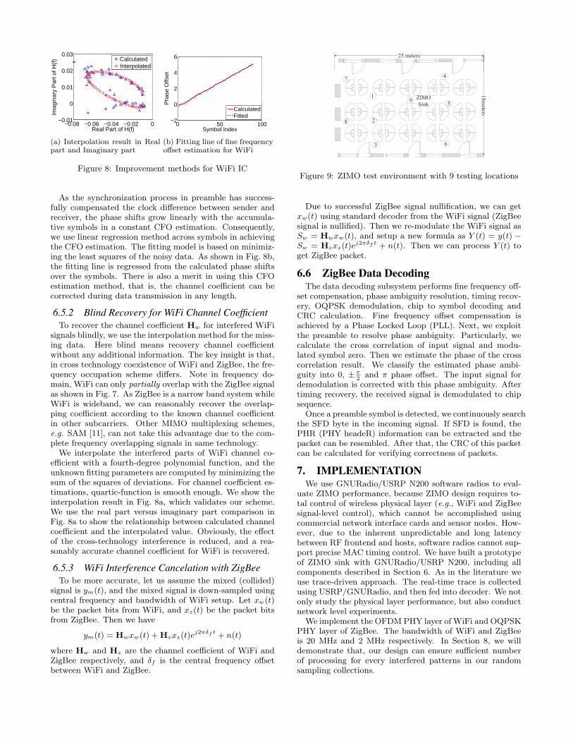
Figure 7: Amplitude, phase of channel coefficient on over-lapping ZigBee and WiFi
ture. Based on the interpolations, timing errors are gen-erated by a zero-crossing Timing Error Detector, filteredby a tunable proportional-plus-integral Loop Filter, and fedinto the NCO control for a timing difference update. TheLoop Bandwidth (normalized by the sample rate) and LoopDamping Factor are tunable for the Loop Filter. The de-fault normalized loop bandwidth is set to 0.07 and the de-fault damping factor is set to 2, such that the PLL quicklylocks to the correct timing while introducing little noise.
6.4 Interference NullifyingIn ZIMO, to remove the WiFi impact, we need to miti-
gate the ZigBee signal temporarily for further WiFi signalcancelation. Inspired by two antenna MIMO-based design,we use interference nullifying process for ZigBee noise miti-gation. When WiFi signal is ‘covered’ by the ZigBee smog,we should first nullify the ZigBee smog according to Eq. (2)in Section 3.
As ZigBee signal is narrow band, for efficient computation,we estimate channel coefficient in time domain. The opti-mal equalizer will minimize the differences between receivedsignal y(t) and the training signal w(t), where
c = argminc
∥w(t)− c ∗ y(t)∥
In the time domain, c = {c−L, · · · , c0, · · · , cL} is a goodestimation of channel coefficient H. For WiFi signal, wecompute the channel coefficient in frequency domain, usingthe FFT of the received signal to divide that of transmittedsignal. Then the interference nullifying technology is appliedfor cross-technology data decoding.
6.5 Interference CancelationIf we can separate WiFi signal from the mixed signal, we
can use standard ZigBee decoder to extract ZigBee pack-ets. The overall processing is called Successive InterferenceCancelation (SIC).
6.5.1 Fine frequency offset estimation for WiFiFine carrier frequency offset (CFO) estimation is neces-
sary to minimize the residual noise after interference cance-lation (IC). Inaccurate CFO estimation will lead to increasedresidual noise over time. A coarse estimation in WiFi train-ing symbols (i.e. STS & LTS) is not enough for IC becauseof limited preamble length and noise. For finer CFO es-timation, we remodulate the received data, and comparethe phase shifts with the received symbol. Note that, ourscheme is data aided, because the remodulated symbol canbe achieved after the coarse CFO estimation.
−0.08 −0.06 −0.04 −0.02 0−0.01
0
0.01
0.02
0.03
Real Part of H(f)
Imag
inar
y P
art o
f H(f
)
CalculatedInterpolated
(a) Interpolation result in Realpart and Imaginary part
0 50 100−2
0
2
4
6
Symbol Index
Pha
se O
ffset
CalculatedFitted
(b) Fitting line of fine frequencyoffset estimation for WiFi
Figure 8: Improvement methods for WiFi IC
As the synchronization process in preamble has success-fully compensated the clock difference between sender andreceiver, the phase shifts grow linearly with the accumula-tive symbols in a constant CFO estimation. Consequently,we use linear regression method across symbols in achievingthe CFO estimation. The fitting model is based on minimiz-ing the least squares of the noisy data. As shown in Fig. 8b,the fitting line is regressed from the calculated phase shiftsover the symbols. There is also a merit in using this CFOestimation method, that is, the channel coefficient can becorrected during data transmission in any length.
6.5.2 Blind Recovery for WiFi Channel CoefficientTo recover the channel coefficient Hw for interfered WiFi
signals blindly, we use the interpolation method for the miss-ing data. Here blind means recovery channel coefficientwithout any additional information. The key insight is that,in cross technology coexistence of WiFi and ZigBee, the fre-quency occupation scheme differs. Note in frequency do-main, WiFi can only partially overlap with the ZigBee signalas shown in Fig. 7. As ZigBee is a narrow band system whileWiFi is wideband, we can reasonably recover the overlap-ping coefficient according to the known channel coefficientin other subcarriers. Other MIMO multiplexing schemes,e.g. SAM [11], can not take this advantage due to the com-plete frequency overlapping signals in same technology.We interpolate the interfered parts of WiFi channel co-
efficient with a fourth-degree polynomial function, and theunknown fitting parameters are computed by minimizing thesum of the squares of deviations. For channel coefficient es-timations, quartic-function is smooth enough. We show theinterpolation result in Fig. 8a, which validates our scheme.We use the real part versus imaginary part comparison inFig. 8a to show the relationship between calculated channelcoefficient and the interpolated value. Obviously, the effectof the cross-technology interference is reduced, and a rea-sonably accurate channel coefficient for WiFi is recovered.
6.5.3 WiFi Interference Cancelation with ZigBeeTo be more accurate, let us assume the mixed (collided)
signal is ym(t), and the mixed signal is down-sampled usingcentral frequency and bandwidth of WiFi setup. Let xw(t)be the packet bits from WiFi, and xz(t) be the packet bitsfrom ZigBee. Then we have
ym(t) = Hwxw(t) +Hzxz(t)ej2πδf t + n(t)
where Hw and Hz are the channel coefficient of WiFi andZigBee respectively, and δf is the central frequency offsetbetween WiFi and ZigBee.
25 meters
18meters
7
2
5
4
1
6
ZIMO
Sink
8
3
9
Figure 9: ZIMO test environment with 9 testing locations
Due to successful ZigBee signal nullification, we can getxw(t) using standard decoder from the WiFi signal (ZigBeesignal is nullified). Then we re-modulate the WiFi signal asSw = Hwxw(t), and setup a new formula as Y (t) = y(t) −Sw = Hzxz(t)e
j2πδf t + n(t). Then we can process Y (t) toget ZigBee packet.
6.6 ZigBee Data DecodingThe data decoding subsystem performs fine frequency off-
set compensation, phase ambiguity resolution, timing recov-ery, OQPSK demodulation, chip to symbol decoding andCRC calculation. Fine frequency offset compensation isachieved by a Phase Locked Loop (PLL). Next, we exploitthe preamble to resolve phase ambiguity. Particularly, wecalculate the cross correlation of input signal and modu-lated symbol zero. Then we estimate the phase of the crosscorrelation result. We classify the estimated phase ambi-guity into 0, ±π
2and π phase offset. The input signal for
demodulation is corrected with this phase ambiguity. Aftertiming recovery, the received signal is demodulated to chipsequence.
Once a preamble symbol is detected, we continuously searchthe SFD byte in the incoming signal. If SFD is found, thePHR (PHY headeR) information can be extracted and thepacket can be resembled. After that, the CRC of this packetcan be calculated for verifying correctness of packets.
7. IMPLEMENTATIONWe use GNURadio/USRP N200 software radios to eval-
uate ZIMO performance, because ZIMO design requires to-tal control of wireless physical layer (e.g., WiFi and ZigBeesignal-level control), which cannot be accomplished usingcommercial network interface cards and sensor nodes. How-ever, due to the inherent unpredictable and long latencybetween RF frontend and hosts, software radios cannot sup-port precise MAC timing control. We have built a prototypeof ZIMO sink with GNURadio/USRP N200, including allcomponents described in Section 6. As in the literature weuse trace-driven approach. The real-time trace is collectedusing USRP/GNURadio, and then fed into decoder. We notonly study the physical layer performance, but also conductnetwork level experiments.
We implement the OFDMPHY layer of WiFi and OQPSKPHY layer of ZigBee. The bandwidth of WiFi and ZigBeeis 20 MHz and 2 MHz respectively. In Section 8, we willdemonstrate that, our design can ensure sufficient numberof processing for every interfered patterns in our randomsampling collections.
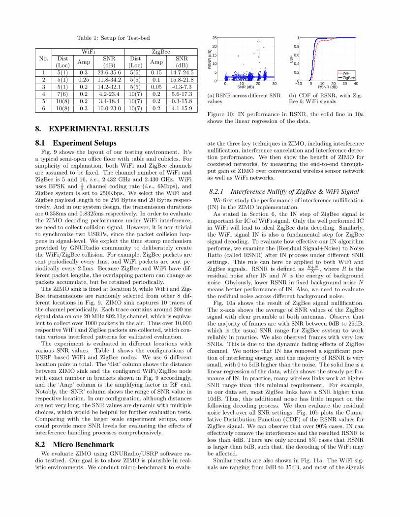
Table 1: Setup for Test-bed
No.WiFi ZigBee
DistAmp
SNR DistAmp
SNR(Loc) (dB) (Loc) (dB)
1 5(1) 0.3 23.6-35.6 5(5) 0.15 14.7-24.52 5(1) 0.25 11.8-34.2 5(5) 0.1 15.8-21.83 5(1) 0.2 14.2-32.1 5(5) 0.05 -0.3-7.34 7(6) 0.2 4.2-23.4 10(7) 0.2 5.6-17.35 10(8) 0.2 3.4-18.4 10(7) 0.2 0.3-15.86 10(8) 0.3 10.0-23.0 10(7) 0.2 4.1-15.9
8. EXPERIMENTAL RESULTS
8.1 Experiment SetupsFig. 9 shows the layout of our testing environment. It’s
a typical semi-open office floor with table and cubicles. Forsimplicity of explanation, both WiFi and ZigBee channelsare assumed to be fixed. The channel number of WiFi andZigBee is 5 and 16, i.e., 2.432 GHz and 2.430 GHz. WiFiuses BPSK and 1
2channel coding rate (i.e., 6Mbps), and
ZigBee system is set to 250Kbps. We select the WiFi andZigBee payload length to be 256 Bytes and 20 Bytes respec-tively. And in our system design, the transmission durationsare 0.358ms and 0.8325ms respectively. In order to evaluatethe ZIMO decoding performance under WiFi interference,we need to collect collision signal. However, it is non-trivialto synchronize two USRPs, since the packet collision hap-pens in signal-level. We exploit the time stamp mechanismprovided by GNURadio community to deliberately createthe WiFi/ZigBee collision. For example, ZigBee packets aresent periodically every 1ms, and WiFi packets are sent pe-riodically every 2.5ms. Because ZigBee and WiFi have dif-ferent packet lengths, the overlapping pattern can change aspackets accumulate, but be retained periodically.The ZIMO sink is fixed at location 9, while WiFi and Zig-
Bee transmissions are randomly selected from other 8 dif-ferent locations in Fig. 9. ZIMO sink captures 10 traces ofthe channel periodically. Each trace contains around 200 mssignal data on one 20 MHz 802.11g channel, which is equiva-lent to collect over 1000 packets in the air. Thus over 10,000respective WiFi and ZigBee packets are collected, which con-tain various interfered patterns for validated evaluation.The experiment is evaluated in different locations with
various SNR values. Table 1 shows the configurations ofUSRP based WiFi and ZigBee nodes. We use 6 differentlocation pairs in total. The ‘dist’ column shows the distancebetween ZIMO sink and the configured WiFi/ZigBee nodewith exact number in brackets shown in Fig. 9 accordingly,and the ‘Amp’ column is the amplifying factor in RF end.Notably, the ‘SNR’ column shows the range of SNR value inrespective location. In our configuration, although distancesare not very long, the SNR values are dynamic with multiplechoices, which would be helpful for further evaluation tests.Comparing with the larger scale experiment setups, ourscould provide more SNR levels for evaluating the effects ofinterference handling processes comprehensively.
8.2 Micro BenchmarkWe evaluate ZIMO using GNURadio/USRP software ra-
dio testbed. Our goal is to show ZIMO is plausible in real-istic environments. We conduct micro-benchmark to evalu-
0 10 20 300
5
10
15
20
25
SNR (dB)
RS
NR
(dB
)
(a) RSNR across different SNRvalues
−10 0 10 20 30 400
0.2
0.4
0.6
0.8
1
RSNR (dB)
CD
F
WiFiZigBee
(b) CDF of RSNR, with Zig-Bee & WiFi signals
Figure 10: IN performance in RSNR, the solid line in 10ashows the linear regression of the data.
ate the three key techniques in ZIMO, including interferencenullification, interference cancelation and interference detec-tion performance. We then show the benefit of ZIMO forcoexisted networks, by measuring the end-to-end through-put gain of ZIMO over conventional wireless sensor networkas well as WiFi networks.
8.2.1 Interference Nullify of ZigBee & WiFi SignalWe first study the performance of interference nullification
(IN) in the ZIMO implementation.As stated in Section 6, the IN step of ZigBee signal is
important for IC of WiFi signal. Only the well performed ICin WiFi will lead to ideal ZigBee data decoding. Similarly,the WiFi signal IN is also a fundamental step for ZigBeesignal decoding. To evaluate how effective our IN algorithmperforms, we examine the (Residual Signal+Noise) to NoiseRatio (called RSNR) after IN process under different SNRsettings. This rule can here be applied to both WiFi andZigBee signals. RSNR is defined as R+N
N, where R is the
residual noise after IN and N is the energy of backgroundnoise. Obviously, lower RSNR in fixed background noise Nmeans better performance of IN. Also, we need to evaluatethe residual noise across different background noise.
Fig. 10a shows the result of ZigBee signal nullification.The x-axis shows the average of SNR values of the ZigBeesignal with clear preamble at both antennas. Observe thatthe majority of frames are with SNR between 0dB to 25dB,which is the usual SNR range for ZigBee system to workreliably in practice. We also observed frames with very lowSNRs. This is due to the dynamic fading effects of ZigBeechannel. We notice that IN has removed a significant por-tion of interfering energy, and the majority of RSNR is verysmall, with 0 to 5dB higher than the noise. The solid line is alinear regression of the data, which shows the steady perfor-mance of IN. In practice, many wireless links work at higherSNR range than this minimal requirement. For example,in our data set, most ZigBee links have a SNR higher than10dB. Thus, this additional noise has little impact on thefollowing decoding process. We then evaluate the residualnoise level over all SNR settings. Fig. 10b plots the Cumu-lative Distribution Function (CDF) of the RSNR values forZigBee signal. We can observe that over 90% cases, IN caneffectively remove the interference and the resulted RSNR isless than 4dB. There are only around 5% cases that RSNRis larger than 5dB, such that, the decoding of the WiFi maybe affected.
Similar results are also shown in Fig. 11a. The WiFi sig-nals are ranging from 0dB to 35dB, and most of the signals
0 10 20 30 40
0
10
20
30
40
SNR (dB)
RS
NR
(dB
)
(a) RSNR of WiFi Nullification
−25 −20 −15 −10 −5 0−10
0
10
20
CSINR (dB)
CS
INR
(dB
)
(b) CSINR of WiFi Cancelation
−20 −10 0 10 200
0.2
0.4
0.6
0.8
1
CSINR (dB)
CD
F
(c) CDF of WiFi Cancelation
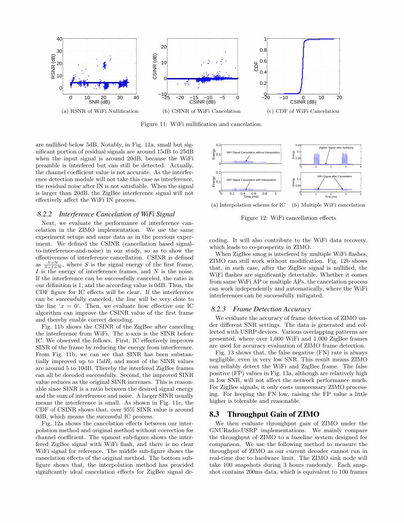
Figure 11: WiFi nullification and cancelation.
are nullified below 5dB. Notably, in Fig. 11a, small but sig-nificant portion of residual signals are around 15dB to 25dBwhen the input signal is around 20dB, because the WiFipreamble is interfered but can still be detected. Actually,the channel coefficient value is not accurate. As the interfer-ence detection module will not take this case as interference,the residual noise after IN is not satisfiable. When the signalis larger than 20dB, the ZigBee interference signal will noteffectively affect the WiFi IN process.
8.2.2 Interference Cancelation of WiFi SignalNext, we evaluate the performance of interference can-
celation in the ZIMO implementation. We use the sameexperiment setups and same data as in the previous exper-iment. We defined the CSINR (cancellation based signal-to-interference-and-noise) in our study, so as to show theeffectiveness of interference cancellation. CSINR is definedas S+N
S+I+N, where S is the signal energy of the first frame,
I is the energy of interference frames, and N is the noise.If the interference can be successfully canceled, the ratio inour definition is 1, and the according value is 0dB. Thus, theCDF figure for IC effects will be clear. If the interferencecan be successfully canceled, the line will be very close tothe line ‘x = 0’. Then, we evaluate how effective our ICalgorithm can improve the CSINR value of the first frameand thereby enable correct decoding.Fig. 11b shows the CSINR of the ZigBee after canceling
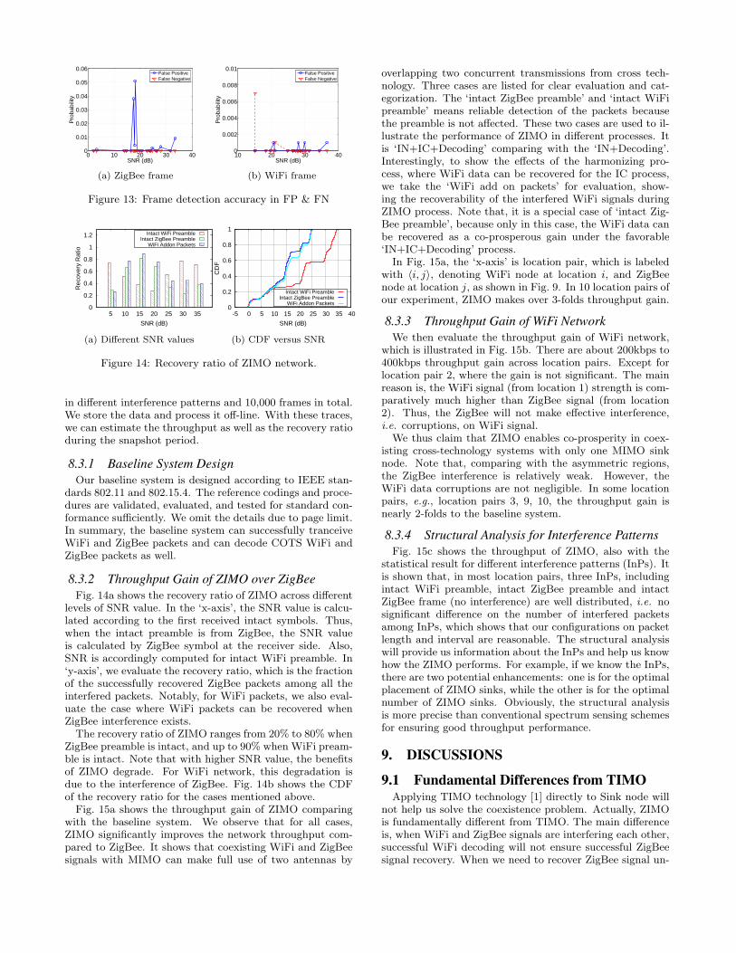
the interference from WiFi. The x-axis is the SINR beforeIC. We observed the follows. First, IC effectively improvesSINR of the frame by reducing the energy from interference.From Fig. 11b, we can see that SINR has been substan-tially improved up to 15dB, and most of the SINR valuesare around 5 to 10dB. Thereby the interfered ZigBee framescan all be decoded successfully. Second, the improved SINRvalue reduces as the original SINR increases. This is reason-able since SINR is a ratio between the desired signal energyand the sum of interference and noise. A larger SINR usuallymeans the interference is small. As shown in Fig. 11c, theCDF of CSINR shows that, over 95% SINR value is around0dB, which means the successful IC process.Fig. 12a shows the cancelation effects between our inter-
polation method and original method without correction forchannel coefficient. The upmost sub-figure shows the inter-fered ZigBee signal with WiFi flash, and there is no clearWiFi signal for reference. The middle sub-figure shows thecancelation effects of the original method. The bottom sub-figure shows that, the interpolation method has providedsignificantly ideal cancelation effects for ZigBee signal de-
0 0.2 0.4 0.6 0.8 10
0.1
0.2
Time (ms)
Ene
rgy
WiFi Signal Cancelation with Interpolation
0
0.1
0.2
Ene
rgy
WiFi Signal Cancelation without Interpolation
(a) Interpolation scheme for IC
0 1 2 3 40
0.05
0.1
0.15
Ene
rgy
ZigBee Signal after Nullifying
0 1 2 3 40
0.05
0.1
Ene
rgy
Time (ms)
WiFi Signal after Cancelation
(b) Multiple WiFi cancelation
Figure 12: WiFi cancellation effects
coding. It will also contribute to the WiFi data recovery,which leads to co-prosperity in ZIMO.
When ZigBee smog is interfered by multiple WiFi flashes,ZIMO can still work without modification. Fig. 12b showsthat, in such case, after the ZigBee signal is nullified, theWiFi flashes are significantly detectable. Whether it comesfrom sameWiFi AP or multiple APs, the cancelation processcan work independently and automatically, where the WiFiinterferences can be successfully mitigated.
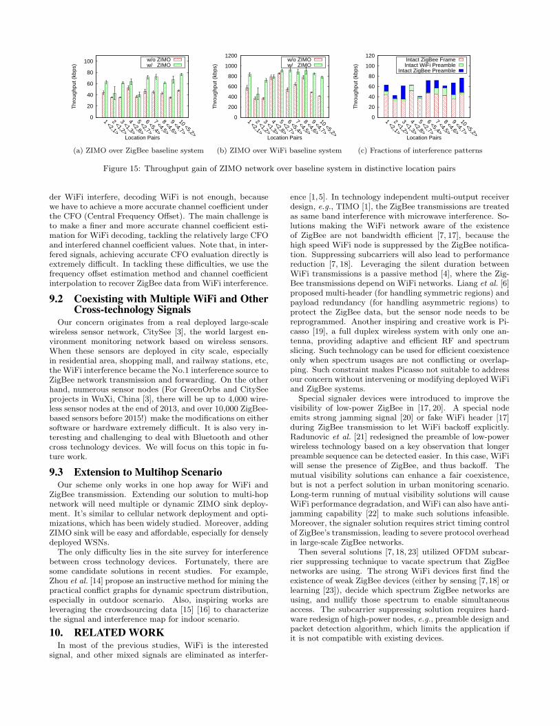
8.2.3 Frame Detection AccuracyWe evaluate the accuracy of frame detection of ZIMO un-
der different SNR settings. The data is generated and col-lected with USRP devices. Various overlapping patterns arepresented, where over 1,000 WiFi and 1,000 ZigBee framesare used for accuracy evaluation of ZIMO frame detection.
Fig. 13 shows that, the false negative (FN) rate is alwaysnegligible, even in very low SNR. This result means ZIMOcan reliably detect the WiFi and ZigBee frame. The falsepositive (FP) values in Fig. 13a, although are relatively highin low SNR, will not affect the network performance much.For ZigBee signals, it only costs unnecessary ZIMO process-ing. For keeping the FN low, raising the FP value a littlehigher is tolerable and reasonable.
8.3 Throughput Gain of ZIMOWe then evaluate throughput gain of ZIMO under the
GNURadio-USRP implementations. We mainly comparethe throughput of ZIMO to a baseline system designed forcomparison. We use the following method to measure thethroughput of ZIMO as our current decoder cannot run inreal-time due to hardware limit. The ZIMO sink node willtake 100 snapshots during 3 hours randomly. Each snap-shot contains 200ms data, which is equivalent to 100 frames
0 10 20 30 400
0.01
0.02
0.03
0.04
0.05
0.06
SNR (dB)
Pro
babi
lity
False PositiveFalse Negative
(a) ZigBee frame
10 20 30 400
0.002
0.004
0.006
0.008
0.01
SNR (dB)
Pro
babi
lity
False PositiveFalse Negative
(b) WiFi frame
Figure 13: Frame detection accuracy in FP & FN
0
0.2
0.4
0.6
0.8
1
1.2
5 10 15 20 25 30 35
Rec
over
y R
atio
SNR (dB)
Intact WiFi PreambleIntact ZigBee Preamble
WiFi Addon Packets
(a) Different SNR values
0
0.2
0.4
0.6
0.8
1
-5 0 5 10 15 20 25 30 35 40
CD
F
SNR (dB)
Intact WiFi PreambleIntact ZigBee Preamble
WiFi Addon Packets
(b) CDF versus SNR
Figure 14: Recovery ratio of ZIMO network.
in different interference patterns and 10,000 frames in total.We store the data and process it off-line. With these traces,we can estimate the throughput as well as the recovery ratioduring the snapshot period.
8.3.1 Baseline System DesignOur baseline system is designed according to IEEE stan-
dards 802.11 and 802.15.4. The reference codings and proce-dures are validated, evaluated, and tested for standard con-formance sufficiently. We omit the details due to page limit.In summary, the baseline system can successfully tranceiveWiFi and ZigBee packets and can decode COTS WiFi andZigBee packets as well.
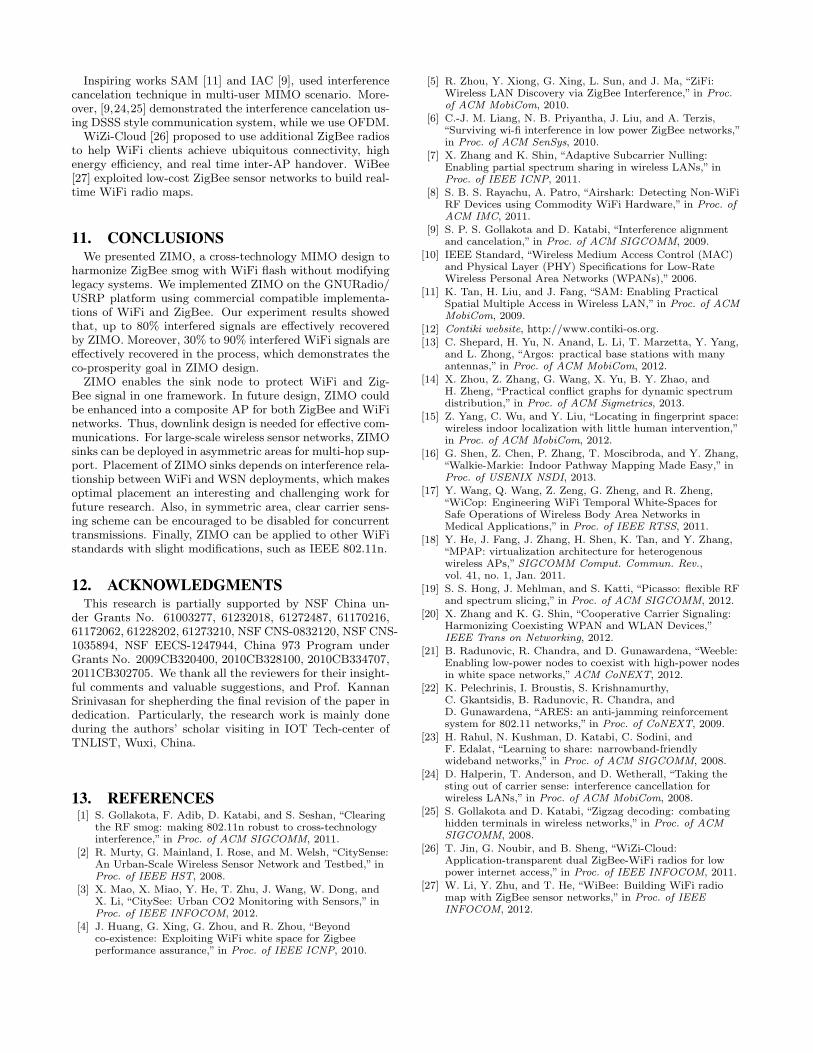
8.3.2 Throughput Gain of ZIMO over ZigBeeFig. 14a shows the recovery ratio of ZIMO across different
levels of SNR value. In the ‘x-axis’, the SNR value is calcu-lated according to the first received intact symbols. Thus,when the intact preamble is from ZigBee, the SNR valueis calculated by ZigBee symbol at the receiver side. Also,SNR is accordingly computed for intact WiFi preamble. In‘y-axis’, we evaluate the recovery ratio, which is the fractionof the successfully recovered ZigBee packets among all theinterfered packets. Notably, for WiFi packets, we also eval-uate the case where WiFi packets can be recovered whenZigBee interference exists.The recovery ratio of ZIMO ranges from 20% to 80% when
ZigBee preamble is intact, and up to 90% when WiFi pream-ble is intact. Note that with higher SNR value, the benefitsof ZIMO degrade. For WiFi network, this degradation isdue to the interference of ZigBee. Fig. 14b shows the CDFof the recovery ratio for the cases mentioned above.Fig. 15a shows the throughput gain of ZIMO comparing
with the baseline system. We observe that for all cases,ZIMO significantly improves the network throughput com-pared to ZigBee. It shows that coexisting WiFi and ZigBeesignals with MIMO can make full use of two antennas by
overlapping two concurrent transmissions from cross tech-nology. Three cases are listed for clear evaluation and cat-egorization. The ‘intact ZigBee preamble’ and ‘intact WiFipreamble’ means reliable detection of the packets becausethe preamble is not affected. These two cases are used to il-lustrate the performance of ZIMO in different processes. Itis ‘IN+IC+Decoding’ comparing with the ‘IN+Decoding’.Interestingly, to show the effects of the harmonizing pro-cess, where WiFi data can be recovered for the IC process,we take the ‘WiFi add on packets’ for evaluation, show-ing the recoverability of the interfered WiFi signals duringZIMO process. Note that, it is a special case of ‘intact Zig-Bee preamble’, because only in this case, the WiFi data canbe recovered as a co-prosperous gain under the favorable‘IN+IC+Decoding’ process.
In Fig. 15a, the ‘x-axis’ is location pair, which is labeledwith ⟨i, j⟩, denoting WiFi node at location i, and ZigBeenode at location j, as shown in Fig. 9. In 10 location pairs ofour experiment, ZIMO makes over 3-folds throughput gain.
8.3.3 Throughput Gain of WiFi NetworkWe then evaluate the throughput gain of WiFi network,
which is illustrated in Fig. 15b. There are about 200kbps to400kbps throughput gain across location pairs. Except forlocation pair 2, where the gain is not significant. The mainreason is, the WiFi signal (from location 1) strength is com-paratively much higher than ZigBee signal (from location2). Thus, the ZigBee will not make effective interference,i.e. corruptions, on WiFi signal.
We thus claim that ZIMO enables co-prosperity in coex-isting cross-technology systems with only one MIMO sinknode. Note that, comparing with the asymmetric regions,the ZigBee interference is relatively weak. However, theWiFi data corruptions are not negligible. In some locationpairs, e.g., location pairs 3, 9, 10, the throughput gain isnearly 2-folds to the baseline system.
8.3.4 Structural Analysis for Interference PatternsFig. 15c shows the throughput of ZIMO, also with the
statistical result for different interference patterns (InPs). Itis shown that, in most location pairs, three InPs, includingintact WiFi preamble, intact ZigBee preamble and intactZigBee frame (no interference) are well distributed, i.e. nosignificant difference on the number of interfered packetsamong InPs, which shows that our configurations on packetlength and interval are reasonable. The structural analysiswill provide us information about the InPs and help us knowhow the ZIMO performs. For example, if we know the InPs,there are two potential enhancements: one is for the optimalplacement of ZIMO sinks, while the other is for the optimalnumber of ZIMO sinks. Obviously, the structural analysisis more precise than conventional spectrum sensing schemesfor ensuring good throughput performance.
9. DISCUSSIONS
9.1 Fundamental Differences from TIMOApplying TIMO technology [1] directly to Sink node will
not help us solve the coexistence problem. Actually, ZIMOis fundamentally different from TIMO. The main differenceis, when WiFi and ZigBee signals are interfering each other,successful WiFi decoding will not ensure successful ZigBeesignal recovery. When we need to recover ZigBee signal un-
0
20
40
60
80
100
1 <2,1>
2 <1,2>
3 <1,3>
4 <2,8>
5 <2,7>
6 <5,4>
7 <4,5>
8 <4,6>
9 <4,7>
10 <5,2>
Thr
ough
put (
kbps
)
Location Pairs
w/o ZIMOw/ ZIMO
(a) ZIMO over ZigBee baseline system
0
200
400
600
800
1000
1200
1 <2,1>
2 <1,2>
3 <1,3>
4 <2,8>
5 <2,7>
6 <5,4>
7 <4,5>
8 <4,6>
9 <4,7>
10 <5,2>
Thr
ough
put (
kbps
)
Location Pairs
w/o ZIMOw/ ZIMO
(b) ZIMO over WiFi baseline system
0
20
40
60
80
100
120
1 <2,1>
2 <1,2>
3 <1,3>
4 <2,8>
5 <2,7>
6 <5,4>
7 <4,5>
8 <4,6>
9 <4,7>
10 <5,2>
Thr
ough
put (
kbps
)
Location Pairs
Intact ZigBee FrameIntact WiFi Preamble
Intact ZigBee Preamble
(c) Fractions of interference patterns
Figure 15: Throughput gain of ZIMO network over baseline system in distinctive location pairs
der WiFi interfere, decoding WiFi is not enough, becausewe have to achieve a more accurate channel coefficient underthe CFO (Central Frequency Offset). The main challenge isto make a finer and more accurate channel coefficient esti-mation for WiFi decoding, tackling the relatively large CFOand interfered channel coefficient values. Note that, in inter-fered signals, achieving accurate CFO evaluation directly isextremely difficult. In tackling these difficulties, we use thefrequency offset estimation method and channel coefficientinterpolation to recover ZigBee data from WiFi interference.
9.2 Coexisting with Multiple WiFi and OtherCross-technology Signals
Our concern originates from a real deployed large-scalewireless sensor network, CitySee [3], the world largest en-vironment monitoring network based on wireless sensors.When these sensors are deployed in city scale, especiallyin residential area, shopping mall, and railway stations, etc,the WiFi interference became the No.1 interference source toZigBee network transmission and forwarding. On the otherhand, numerous sensor nodes (For GreenOrbs and CitySeeprojects in WuXi, China [3], there will be up to 4,000 wire-less sensor nodes at the end of 2013, and over 10,000 ZigBee-based sensors before 2015!) make the modifications on eithersoftware or hardware extremely difficult. It is also very in-teresting and challenging to deal with Bluetooth and othercross technology devices. We will focus on this topic in fu-ture work.
9.3 Extension to Multihop ScenarioOur scheme only works in one hop away for WiFi and
ZigBee transmission. Extending our solution to multi-hopnetwork will need multiple or dynamic ZIMO sink deploy-ment. It’s similar to cellular network deployment and opti-mizations, which has been widely studied. Moreover, addingZIMO sink will be easy and affordable, especially for denselydeployed WSNs.The only difficulty lies in the site survey for interference
between cross technology devices. Fortunately, there aresome candidate solutions in recent studies. For example,Zhou et al. [14] propose an instructive method for mining thepractical conflict graphs for dynamic spectrum distribution,especially in outdoor scenario. Also, inspiring works areleveraging the crowdsourcing data [15] [16] to characterizethe signal and interference map for indoor scenario.
10. RELATED WORKIn most of the previous studies, WiFi is the interested
signal, and other mixed signals are eliminated as interfer-
ence [1,5]. In technology independent multi-output receiverdesign, e.g., TIMO [1], the ZigBee transmissions are treatedas same band interference with microwave interference. So-lutions making the WiFi network aware of the existenceof ZigBee are not bandwidth efficient [7, 17], because thehigh speed WiFi node is suppressed by the ZigBee notifica-tion. Suppressing subcarriers will also lead to performancereduction [7, 18]. Leveraging the silent duration betweenWiFi transmissions is a passive method [4], where the Zig-Bee transmissions depend on WiFi networks. Liang et al. [6]proposed multi-header (for handling symmetric regions) andpayload redundancy (for handling asymmetric regions) toprotect the ZigBee data, but the sensor node needs to bereprogrammed. Another inspiring and creative work is Pi-casso [19], a full duplex wireless system with only one an-tenna, providing adaptive and efficient RF and spectrumslicing. Such technology can be used for efficient coexistenceonly when spectrum usages are not conflicting or overlap-ping. Such constraint makes Picasso not suitable to addressour concern without intervening or modifying deployed WiFiand ZigBee systems.
Special signaler devices were introduced to improve thevisibility of low-power ZigBee in [17, 20]. A special nodeemits strong jamming signal [20] or fake WiFi header [17]during ZigBee transmission to let WiFi backoff explicitly.Radunovic et al. [21] redesigned the preamble of low-powerwireless technology based on a key observation that longerpreamble sequence can be detected easier. In this case, WiFiwill sense the presence of ZigBee, and thus backoff. Themutual visibility solutions can enhance a fair coexistence,but is not a perfect solution in urban monitoring scenario.Long-term running of mutual visibility solutions will causeWiFi performance degradation, andWiFi can also have anti-jamming capability [22] to make such solutions infeasible.Moreover, the signaler solution requires strict timing controlof ZigBee’s transmission, leading to severe protocol overheadin large-scale ZigBee networks.
Then several solutions [7, 18, 23] utilized OFDM subcar-rier suppressing technique to vacate spectrum that ZigBeenetworks are using. The strong WiFi devices first find theexistence of weak ZigBee devices (either by sensing [7,18] orlearning [23]), decide which spectrum ZigBee networks areusing, and nullify those spectrum to enable simultaneousaccess. The subcarrier suppressing solution requires hard-ware redesign of high-power nodes, e.g., preamble design andpacket detection algorithm, which limits the application ifit is not compatible with existing devices.
Inspiring works SAM [11] and IAC [9], used interferencecancelation technique in multi-user MIMO scenario. More-over, [9,24,25] demonstrated the interference cancelation us-ing DSSS style communication system, while we use OFDM.WiZi-Cloud [26] proposed to use additional ZigBee radios
to help WiFi clients achieve ubiquitous connectivity, highenergy efficiency, and real time inter-AP handover. WiBee[27] exploited low-cost ZigBee sensor networks to build real-time WiFi radio maps.
11. CONCLUSIONSWe presented ZIMO, a cross-technology MIMO design to
harmonize ZigBee smog with WiFi flash without modifyinglegacy systems. We implemented ZIMO on the GNURadio/USRP platform using commercial compatible implementa-tions of WiFi and ZigBee. Our experiment results showedthat, up to 80% interfered signals are effectively recoveredby ZIMO. Moreover, 30% to 90% interfered WiFi signals areeffectively recovered in the process, which demonstrates theco-prosperity goal in ZIMO design.ZIMO enables the sink node to protect WiFi and Zig-
Bee signal in one framework. In future design, ZIMO couldbe enhanced into a composite AP for both ZigBee and WiFinetworks. Thus, downlink design is needed for effective com-munications. For large-scale wireless sensor networks, ZIMOsinks can be deployed in asymmetric areas for multi-hop sup-port. Placement of ZIMO sinks depends on interference rela-tionship between WiFi and WSN deployments, which makesoptimal placement an interesting and challenging work forfuture research. Also, in symmetric area, clear carrier sens-ing scheme can be encouraged to be disabled for concurrenttransmissions. Finally, ZIMO can be applied to other WiFistandards with slight modifications, such as IEEE 802.11n.
12. ACKNOWLEDGMENTSThis research is partially supported by NSF China un-
der Grants No. 61003277, 61232018, 61272487, 61170216,61172062, 61228202, 61273210, NSF CNS-0832120, NSF CNS-1035894, NSF EECS-1247944, China 973 Program underGrants No. 2009CB320400, 2010CB328100, 2010CB334707,2011CB302705. We thank all the reviewers for their insight-ful comments and valuable suggestions, and Prof. KannanSrinivasan for shepherding the final revision of the paper indedication. Particularly, the research work is mainly doneduring the authors’ scholar visiting in IOT Tech-center ofTNLIST, Wuxi, China.
13. REFERENCES[1] S. Gollakota, F. Adib, D. Katabi, and S. Seshan, “Clearing
the RF smog: making 802.11n robust to cross-technologyinterference,” in Proc. of ACM SIGCOMM, 2011.
[2] R. Murty, G. Mainland, I. Rose, and M. Welsh, “CitySense:An Urban-Scale Wireless Sensor Network and Testbed,” inProc. of IEEE HST, 2008.
[3] X. Mao, X. Miao, Y. He, T. Zhu, J. Wang, W. Dong, andX. Li, “CitySee: Urban CO2 Monitoring with Sensors,” inProc. of IEEE INFOCOM, 2012.
[4] J. Huang, G. Xing, G. Zhou, and R. Zhou, “Beyondco-existence: Exploiting WiFi white space for Zigbeeperformance assurance,” in Proc. of IEEE ICNP, 2010.
[5] R. Zhou, Y. Xiong, G. Xing, L. Sun, and J. Ma, “ZiFi:Wireless LAN Discovery via ZigBee Interference,” in Proc.of ACM MobiCom, 2010.
[6] C.-J. M. Liang, N. B. Priyantha, J. Liu, and A. Terzis,“Surviving wi-fi interference in low power ZigBee networks,”in Proc. of ACM SenSys, 2010.
[7] X. Zhang and K. Shin, “Adaptive Subcarrier Nulling:Enabling partial spectrum sharing in wireless LANs,” inProc. of IEEE ICNP, 2011.
[8] S. B. S. Rayachu, A. Patro, “Airshark: Detecting Non-WiFiRF Devices using Commodity WiFi Hardware,” in Proc. ofACM IMC, 2011.
[9] S. P. S. Gollakota and D. Katabi, “Interference alignmentand cancelation,” in Proc. of ACM SIGCOMM, 2009.
[10] IEEE Standard, “Wireless Medium Access Control (MAC)and Physical Layer (PHY) Specifications for Low-RateWireless Personal Area Networks (WPANs),” 2006.
[11] K. Tan, H. Liu, and J. Fang, “SAM: Enabling PracticalSpatial Multiple Access in Wireless LAN,” in Proc. of ACMMobiCom, 2009.
[12] Contiki website, http://www.contiki-os.org.[13] C. Shepard, H. Yu, N. Anand, L. Li, T. Marzetta, Y. Yang,
and L. Zhong, “Argos: practical base stations with manyantennas,” in Proc. of ACM MobiCom, 2012.
[14] X. Zhou, Z. Zhang, G. Wang, X. Yu, B. Y. Zhao, andH. Zheng, “Practical conflict graphs for dynamic spectrumdistribution,” in Proc. of ACM Sigmetrics, 2013.
[15] Z. Yang, C. Wu, and Y. Liu, “Locating in fingerprint space:wireless indoor localization with little human intervention,”in Proc. of ACM MobiCom, 2012.
[16] G. Shen, Z. Chen, P. Zhang, T. Moscibroda, and Y. Zhang,“Walkie-Markie: Indoor Pathway Mapping Made Easy,” inProc. of USENIX NSDI, 2013.
[17] Y. Wang, Q. Wang, Z. Zeng, G. Zheng, and R. Zheng,“WiCop: Engineering WiFi Temporal White-Spaces forSafe Operations of Wireless Body Area Networks inMedical Applications,” in Proc. of IEEE RTSS, 2011.
[18] Y. He, J. Fang, J. Zhang, H. Shen, K. Tan, and Y. Zhang,“MPAP: virtualization architecture for heterogenouswireless APs,” SIGCOMM Comput. Commun. Rev.,vol. 41, no. 1, Jan. 2011.
[19] S. S. Hong, J. Mehlman, and S. Katti, “Picasso: flexible RFand spectrum slicing,” in Proc. of ACM SIGCOMM, 2012.
[20] X. Zhang and K. G. Shin, “Cooperative Carrier Signaling:Harmonizing Coexisting WPAN and WLAN Devices,”IEEE Trans on Networking, 2012.
[21] B. Radunovic, R. Chandra, and D. Gunawardena, “Weeble:Enabling low-power nodes to coexist with high-power nodesin white space networks,”ACM CoNEXT, 2012.
[22] K. Pelechrinis, I. Broustis, S. Krishnamurthy,C. Gkantsidis, B. Radunovic, R. Chandra, andD. Gunawardena, “ARES: an anti-jamming reinforcementsystem for 802.11 networks,” in Proc. of CoNEXT, 2009.
[23] H. Rahul, N. Kushman, D. Katabi, C. Sodini, andF. Edalat, “Learning to share: narrowband-friendlywideband networks,” in Proc. of ACM SIGCOMM, 2008.
[24] D. Halperin, T. Anderson, and D. Wetherall, “Taking thesting out of carrier sense: interference cancellation forwireless LANs,” in Proc. of ACM MobiCom, 2008.
[25] S. Gollakota and D. Katabi, “Zigzag decoding: combatinghidden terminals in wireless networks,” in Proc. of ACMSIGCOMM, 2008.
[26] T. Jin, G. Noubir, and B. Sheng, “WiZi-Cloud:Application-transparent dual ZigBee-WiFi radios for lowpower internet access,” in Proc. of IEEE INFOCOM, 2011.
[27] W. Li, Y. Zhu, and T. He, “WiBee: Building WiFi radiomap with ZigBee sensor networks,” in Proc. of IEEEINFOCOM, 2012.