zenoah g230pu petrol engine
TRANSCRIPT
8/11/2019 Zenoah G230PU Petrol Engine
http://slidepdf.com/reader/full/zenoah-g230pu-petrol-engine 1/4
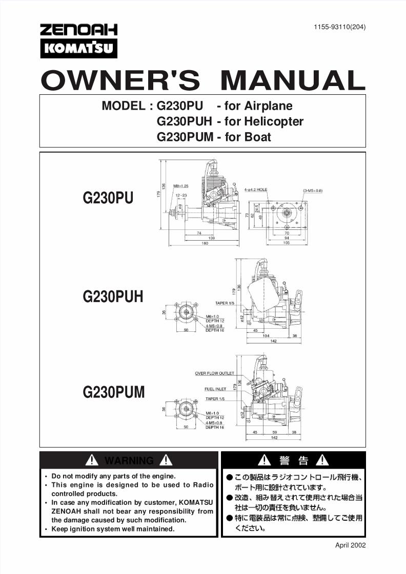
OWNER'S MANUALMODEL : G230PU - for Airplane
G230PUH - for Helicopter
G230PUM - for Boat
G230PU
G230PUH
G230PUM
April 2002
1155-93110(204)
• Do not modify any parts of the engine.
• This engine is designed to be used to Radio
controlled products.
• In case any modification by customer, KOMATSUZENOAH shall not bear any responsibility from
the damage caused by such modification.
• Keep ignition system well maintained.
WARNING
8/11/2019 Zenoah G230PU Petrol Engine
http://slidepdf.com/reader/full/zenoah-g230pu-petrol-engine 2/4
1. Propeller for airplaneThe recommended prop sizes are as shown in the table bellow.
This engine with a standard muffler produces the maximum
output when the engine is running at about 10,000rpm. Be sure
to use a propeller which makes the engine speed
approximately 7,000~9,500rpm while the airplane is flying.
[ NOTE ]
When mounting the spinner, set a pin on the hub with more
than 3mm of diameter, thus preventing slipping.
2. Rotor for helicopterAdjust the rotor-pitch to obtain 9,000~10,000 rpm of the engine
at full throttle operation.
3. Screw Propeller for boatThe exhaust system (e.g., muffler) is not equipped with as
standard. When you select the exhaust system for the engine,
check how many the engine speed (rpm) is required when the
maximum output is generated by using the muffler you select.
And then decide the appropriate the screw propeller that would
meet such engine speed (rpm) that the muffler required.
In general, standard size of the screw propeller (Surface prop
type) are as follows:
1. SAFETY PRECAUTIONS
2. MOUNTING G230PU
3. PROPELLER, ROTOR & SCREW PROPELLER
4. FUEL
5. OPERATION
Make sure that the G230PU is mounted on the aircraft grade
plywood with more than 6mm of thickness or a mount of
equivalent strength and is firmly fixed with 4 bolts.
[ NOTE ]1. Be sure to set flat washers or metal plate on the reverse side of
the mount to prevent bolts from sinking into the mount. Before
be sure to check for loose bolts.
2. Since the engine is equipped with a float-less carburetor with a
diaphragm pump, the direction of cylinder and position of fuel
tank can be freely selected .
Hand flip startSince the G230PU is equipped with the ultra compact C.D.I. type
flywheel magneto ignition system, it should be started according
to the following procedure;
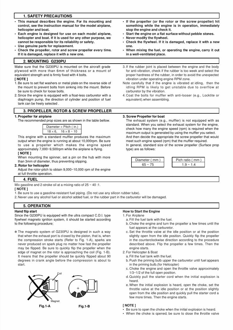
The magneto system of G230PU is designed in such a waythat when the exhaust port is closed by the piston, that is, when
the compression stroke starts (Refer to Fig. 1-A), sparks are
never produced on spark plug no matter how fast the propeller
may be flipped. Be sure to quickly flip the propeller when the
edge of magnet on the rotor is approaching the coil (Fig. 1-B).
It means that the propeller should be quickly flipped about 90
degrees in crank angle before the compression is about to
start.
How to Start the Engine1. For Airplane
a. FiII the fuel tank with the fuel.
b. Choke the engine and turn the propeller a few times until the
fuel appears at the carburetor.
c. Set the throttle valve at the idle position or at the positionslightly open from the idle position. Quickly flip the propeller
in the counterclockwise direction according to the procedure
described above. Flip the propeller a few times. Then the
engine starts.
2. For Helicopter & Boat
a. Fill the fuel tank with the fuel.
b. Push the priming bulb upper the carburetor until fuel appears
in the priming bulb.(for Helicopter)
c. Choke the engine and open the throttle valve approximately
1/3~1/2 of the full open position.
d.Quickly pull the starter cord when the initial explosion is
heard.
e. When the initial explosion is heard, open the choke, set the
throttle valve at the idle position or at the position slightlyopen from the idle position and quickly pull the starter cord a
few more times. Then the engine starts.
[ NOTE ]
• Be sure to open the choke when the initial explosion is heard.
• When the choke is opened, be sure to close the throttle valve
3. If the rubber joint is placed between the engine and the body
for anti-vibration, check if the rubber is too week and select the
proper hardness of the rubber, in order to avoid the unexpected
vibration under operating engine RPM zone.
Note carefully that if the engine is vibrated at idling, then the
idling RPM is likely to get unstable due to overflow at
carburetor by the vibration.
4.Coat the bolts for muffler with anti-looser (e.g., Locktite or
equivalent).when assembling.
• This manual describes the engine. For its mounting and
control, see the instruction manual for the model airplane,
helicopter and boat.
• Each engine is designed for use on each model airplane,
helicopter and boat. If it is used for any other purpose, we
cannot be responsible for its reliability or safety.
• Use genuine parts for replacement.
• Check the propeller, rotor and screw propeller every time.
If it is damaged, replace it with a new one.
• If the propeller (or the rotor or the screw propeller) hit
something while the engine is in operation, immediately
stop the engine and check it.
• Start the engine on a flat surface without pebble stones.
• Never modify the fIywheeI.
• Check the fIywheel. If it is damaged, replace it with a new
one.
• When mixing the fuel, or operating the engine, carry it out
in a well-ventilated place.
Magnet
Coil
Fig.1-A Fig.1-B
Diameter × Pitch ( in.)
18 × 6, 16 × 8 ~ 10
Diameter ( mm )
65 ~ 75
Pich ratio ( mm )
1.9 ~ 1.4
Mix gasoline and 2-stroke oil at a mixing ratio of 25 ~ 40 :1.
[ NOTE ]
1. Be sure to use a gasoline-resistant fuel piping. (Do not use any silicon rubber tube).
2. Never use any alcohol fuel or alcohol added fuel, or the rubber part in the carburetor will be damaged.
8/11/2019 Zenoah G230PU Petrol Engine
http://slidepdf.com/reader/full/zenoah-g230pu-petrol-engine 3/4
6. CARBURETOR ADJUSTMENT
7. ENGINE BREAK-IN
8. SERVICING
to a position near the idle position before starting the next flipping
(If the engine is started while the throttle is wide open, a great
thrusting force is produced, which is very dangerous).
• Be sure to wear a thick glove when flipping the propeller. Use all
fingers, except thumb, for the flipping operation.
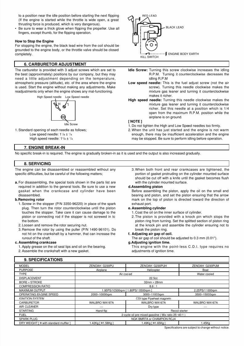
How to Stop the Engine
For stopping the engine, the black lead wire from the coil should be
grounded to the engine body, or the throttle valve should be closed
completely.
The carburetor is provided with 3 adjust screws which are set to
the best (approximately) positions by our company, but they may
need a litt le adjustment depending on the temperature,
atmospheric pressure (altitude), etc. of the area where the engine
is used. Start the engine without making any adjustments. Make
readjustments only when the engine shows any mal-functioning.
1. Standard opening of each needle as follows;
Low speed needle: 11 / 8 ± 1 / 4
High speed needle: 13 / 8 ± 1 / 4
Idle Screw: Turning this screw clockwise increases the idling
R.P.M. Turning it counterclockwise decreases the
idling R.P.M
Low speed needle: This is the fuel adjust screw (not the air
screw). Turning this needle clockwise makes the
mixture gas leaner and turning it counterclockwise
makes it richer.
High speed needle: Turning this needle clockwise makes the
mixture gas leaner and turning it counterclockwise
richer. Set this needle at a position which is 1/4
open from the maximum R.P.M. position while the
airplane is on ground.
[ NOTE ]1. Do not tighten the High and Low Speed needles too firmly.
2. When the unit has just started and the engine is not warm
enough, there may be insufficient acceleration and the engine
may be stopped. Be sure to perform idling before operation.
No specific break-in is required. The engine is gradually broken-in as it is used and the output is also increased gradually.
The engine can be disassembled or reassembled without any
specific difficulties, but be careful of the following matters;
a. For disassembling, the special tools shown in the parts list arerequired in addition to the general tools. Be sure to use a new
gasket when the crankcase and cylinder have been
disassembled.
b.Removing rotor1. Screw in the stopper (P/N 3350-96220) in place of the spark
plug. Then turn the rotor counterclockwise until the piston
touches the stopper. Take care it can cause damage to the
piston or connecting rod if the stopper is not screwed in to
the bottom.
2. Loosen and remove the rotor securing nut.
3. Remove the rotor by using the puller (P/N 1490-96101). Do
not hit on the crankshaft by a hammer, that can increase the
runout of the shaft.
c. Assembling crankcase1. Apply grease on the oil seal lips and oil on the bearing.
2. Assemble the crankshaft with a new gasket.
3.When both front and rear crankcases are tightened, the
portion of gasket protruding on the cylinder mounted surface
should be cut off with a knife until the gasket becomes flush
with the cylinder mounted surface.d.Assembling piston
Before assembling the piston, apply the oil on the small end
bearing and piston, and set the piston ensuring that the arrow
mark on the top of piston is directed toward the direction of
exhaust port.
e. Assembling cylinder
1. Coat the oil on the inner surface of cylinder.
2.The piston is provided with a knock pin which stops the
piston ring from turning. Set the splitted section of piston ring
at the knock pin and assemble the cylinder ensuring not to
break the piston ring.
f. Adjusting air gap of coil.
The air gap of coil should be adjusted to 0.3 mm (0.01").
g.Adjusting ignition time.This engine with the point-less C.D.I. type requires no
adjustments of ignition time.
Low Speed needleHigh Speed needle
Idle Screw
H L
KILL SWITCH
BLACK LEAD
RED LEAD
ENGINE BODY EARTH
9. SPECIFICATIONS
Specifications are subject to change without notice.
MODEL ZENOAH G230PU ZENOAH G230PUH ZENOAH G230PUM
PURPOSE Airplane Helicopter Boat
TYPE Air cooled Water cooled
DISPLACEMENT 22.5cc
BORE × STROKE 32mm × 28mm
COMPRESSION RATIO 8.6 : 1
MAXIMUM OUTPUT 1.95PS/10500rpm [ 1.80PS/10500rpm ] 2.25PS/11000rpm
OPERATING ENGINE SPEED 2000~10000rpm 3000~11000rpm 3500~15000rpm
IGNITION SYSTEM CDI type Flywheel magneto
CARBURETOR WALBRO WA197A WALBRO WA167A WALBRO WA167AAIR CLEANER Dry type
STARTING Hand flip Recoil starter
FUEL 2-cycle oil pre-mixed gasoline ( Mix ratio 25~40:1 )
SPARK PLUG NGK BMR7A or CHAMPION RCJ4
DRY WEIGHT [ with standard muffler ] 1.42Kg [ 1.58Kg ] 1.49Kg [ 1.65Kg ] 1.45Kg
8/11/2019 Zenoah G230PU Petrol Engine
http://slidepdf.com/reader/full/zenoah-g230pu-petrol-engine 4/4
Q' ty per unit
PU PUH PUMDescriptionParts No.
Index
No.
Q' ty per unit
PU PUH PUMDescriptionParts No.
Index
No.
Index Q’tyNo. Parts No. Description /Unit
Index Q’tyNo. Parts No. Description /Unit
Index Q’tyNo. Parts No. Description /Unit
Index Q’tyNo. Parts No. Description /Unit
1 1148-12112 CYLINDER 1 1 02 1160-12111 CYLINDER 0 0 13 1160-12210 JACKET 0 0 14 07851-00515 JOINT 0 0 25 07000-03038 O RING 3×38 0 0 16 1160-12320 O RING 1.5×19.5 0 0 17 1160-12330 BOLT M3×8 0 0 28 1140-13121 GASKET CYL 1 1 19 3310-12281 BOLT M5×20 4 4 4
10 1140-13151 GASKET INSU 1 1 111 1148-13161 INSULATOR 1 1 112 3330-14121 GASKET CARB 1 2 1
1155-21101 CRANKCASE COMP 1 1 113 CRANKCASE (R) 1 1 114 CRANKCASE (F) 1 1 115 2629-21130 PIN 3 3 316 1140-21141 GASKET CASE 1 1 117 2169-21210 SEAL 12×22×7 1 1 118 1155-21240 BEARING 2 2 219 04065-02812 RING SNAP 1 1 120 06034-06001 BEARING 1 1 0
21 1850-21220 SEAL OIL 0 0 122 01252-30530 BOLT M5×30 4 4 423 5600-41111 PISTON 1 1 124 1100-41210 RING PISTON 2 2 2
Head Office : 1-9 Minamidai, Kawagoe-city,
Saitama, 350-1192 Japan
Phone: (+81)492-43-1117 Fax: (+81)492-43-7197
Printed in Japan
25 1101-41310 PIN PISTON 1 1 126 1260-41320 RING SNAP 2 2 227 5500-41410 BEARING 1 1 128 1101-41340 WASHER THRUST 2 2 229 1155-42000 CRANKSHAFT C 1 1 130 1155-74110 PLATE MOUNT 1 1 131 0262-10516 SCREW CM5×16 3 3 332 1650-43230 NUT 1 0 033 1160-75210 PULLEY 0 1 134 1861-75101 RECOlL ASSY 0 1 135 0263-30414 SCREW M4×14 0 4 436 1000-43240 KEY 1 1 137 1140-43250 SHIM 0~2 0~2 0~238 2629-71210 COIL SO (GRAY) 1 0 039 1160-71211 COIL SO (RED) 0 1 140 2629-71311 COIL IG 1 1 141 0263-30414 SCREW M4×14 2 2 242 2629-72210 CAP PLUG (BLACK) 1 0 043 2850-72110 CAP PLUG (RED) 0 1 144 1400-72121 SPRING 1 1 145 0260-30422 SCREW M4×22 2 2 2
46-1 1148-73120 SPARKPLUG BMR7A 1 0 046-2 1155-73120 SPARKPLUG RCJ4 0 1 147 0263-90550 SCREW M5×50 2 0 248 0263-30555 SCREW M5×55 0 2 0
49 1142-83110 SPACER 5×10×I.6 2 0 250 1751-82002 AIRCREANER 0 1 051 1145-81002 CARBURETOR 197A 1 0 052 1148-81002 CARBURETOR 167A 0 1 153 0263-90520 SCREW M5X20 2 2 254 1155-71110 ROTOR 1 1 1
55-1 1155-15110 MUFFLER 1 0 055-2 1148-08010 MUFFLER 0 1 056 1140-13141 GASKET MUFF 1 2 0
57-1 01252-30550 BOLT M5×50 2 0 057-2 01252-30560 BOLT M5×60 0 2 058-1 0263-30408 SCREW M4×8 1 0 058-2 0263-90416 SCREW M4×16 0 1 059 1152-43260 HUB 1 0 060 1152-43281 STUD 1 0 061 1152-43290 WASHER HUB 1 0 062 3350-53410 NUT 1 0 063 3350-96220 STOPPER (OPT) 1 1 164 1490-96101 PULLER ASSY (OPT) 1 1 165 1110-91320 SOCKET 1 1 166 1145-15412 SPACER 0 1 0
67 1158-15420 SPACER 0 1 068 1101-96220 ROD-A (OPT) 1 1 1
Q' ty per unit
PU PUH PUMDescriptionParts No.
Index
No.
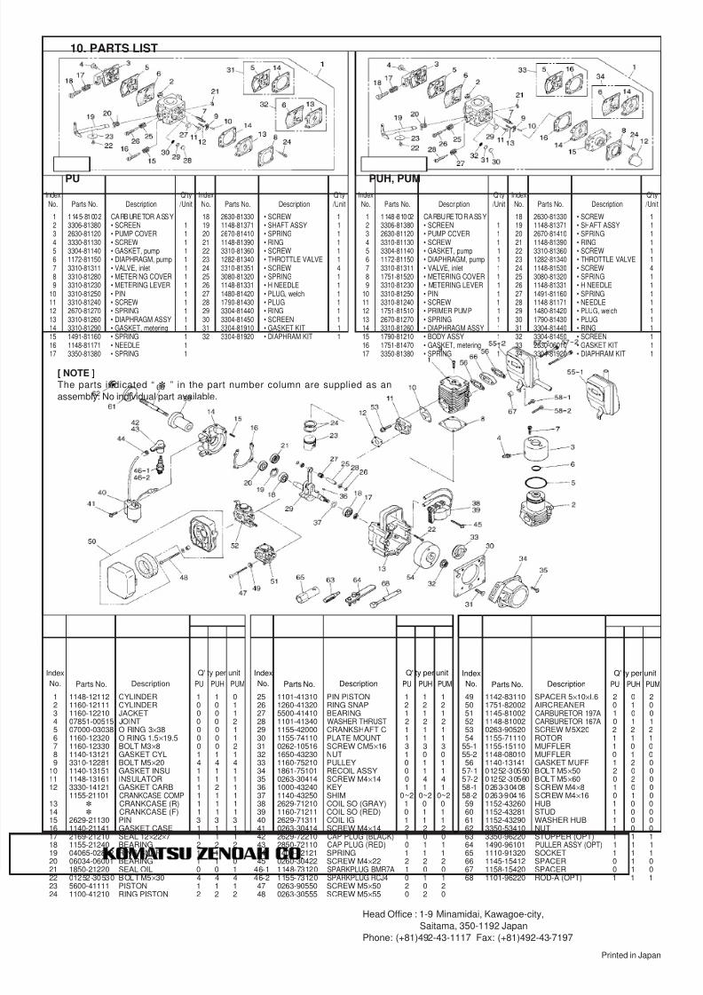
10. PARTS LIST
PUH, PUMPU
[ NOTE ]
The parts indicated “ ” in the part number column are supplied as an
assembly. No individual part available.
1 1145-81002 CARBURETOR ASSY2 3306-81380 • SCREEN 13 2630-81120 • PUMP COVER 14 3330-81130 • SCREW 15 3304-81140 • GASKET, pump 16 1172-81150 • DIAPHRAGM, pump 17 3310-81311 • VALVE, inlet 18 3310-81280 • METERING COVER 19 3310-81230 • METERING LEVER 1
10 3310-81250 • PIN 111 3310-81240 • SCREW 112 2670-81270 • SPRING 113 3310-81260 • DIAPHRAGM ASSY 114 3310-81290 • GASKET, metering 115 1491-81160 • SPRING 1
16 1148-81171 • NEEDLE 117 3350-81380 • SPRING 1
18 2630-81330 • SCREW 119 1148-81371 • SHAFT ASSY 120 2670-81410 • SPRING 121 1148-81390 • RING 122 3310-81360 • SCREW 123 1282-81340 • THROTTLE VALVE 124 3310-81351 • SCREW 425 3080-81320 • SPRING 126 1148-81331 • H NEEDLE 127 1480-81420 • PLUG, welch 128 1790-81430 • PLUG 129 3304-81440 • RING 130 3304-81450 • SCREEN 131 3304-81910 • GASKET KIT 132 3304-81920 • DIAPHRAM KIT 1
1 1148-81002 CARBURETOR ASSY2 3306-81380 • SCREEN 13 2630-81120 • PUMP COVER 14 3310-81130 • SCREW 15 3304-81140 • GASKET, pump 16 1172-81150 • DIAPHRAGM, pump 17 3310-81311 • VALVE, inlet 18 1751-81520 • METERING COVER 19 3310-81230 • METERING LEVER 1
10 3310-81250 • PIN 111 3310-81240 • SCREW 112 1751-81510 • PRIMER PUMP 113 2670-81270 • SPRING 114 3310-81260 • DIAPHRAGM ASSY 115 1790-81210 • BODY ASSY 1
16 1751-81470 • GASKET, metering 117 3350-81380 • SPRING 1
18 2630-81330 • SCREW 119 1148-81371 • SHAFT ASSY 120 2670-81410 • SPRING 121 1148-81390 • RING 122 3310-81360 • SCREW 123 1282-81340 • THROTTLE VALVE 124 1148-81530 • SCREW 425 3080-81320 • SPRING 126 1148-81331 • H NEEDLE 127 1491-81160 • SPRING 128 1148-81171 • NEEDLE 129 1480-81420 • PLUG, welch 130 1790-81430 • PLUG 131 3304-81440 • RING 132 3304-81450 • SCREEN 1
33 2630-06010 • GASKET KIT 134 3304-81920 • DIAPHRAM KIT 1