z-8550a instruction manual
TRANSCRIPT

Z-8550A Z-8560A
Please read this manual before using the machine. Please keep this manual within easy reach for quick reference.
ELECTRONIC DIRECT DRIVE ZIGZAG LOCK STITCHER ELECTRONIC DIRECT DRIVE ZIGZAG LOCK STITCHER WITH THREAD TRIMMER
INSTRUCTION MANUAL

Z-8550A, 8560A
Thank you very much for buying a BROTHER sewing machine. Before using your new machine, please read the safety instructions below and the explanations given in the instruction manual. With industrial sewing machines, it is normal to carry out work while positioned directly in front of moving parts such as the needle and thread take-up, and consequently there is always a danger of injury that can be caused by these parts. Follow the instructions from training personnel and instructors regarding safe and correct operation before operating the machine so that you will know how to use it correctly.

Z-8550A, 8560A i
SAFETY INSTRUCTIONS �
[1] Safety indications and their meanings This instruction manual and the indications and symbols that are used on the machine itself are provided in order to ensure safe operation of this machine and to prevent accidents and injury to yourself or other people.
Indications
DANGER The instructions which follow this term indicate situations where failure to follow the instructions will almost certainly result in death or severe injury.
CAUTION The instructions which follow this term indicate situations where failure to follow the instructions could cause injury when using the machine or physical damage to equipment and surroundings.
Symbols
· · · · · This symbol ( ) indicates something that you should be careful of. The picture inside the triangle indicates the nature of the caution that must be taken. (For example, the symbol at left means “beware of injury”.)
· · · · · This symbol ( ) indicates something that you must not do.
· · · · · This symbol ( ) indicates something that you must do. The picture inside the circle indicates the nature of the thing that must be done. (For example, the symbol at left means “you must make the ground connection”.)
Z-8550A, 8560A ii
[2] Notes on safety
DANGER Wait at least 5 minutes after turning off the power switch and disconnecting the power cord from the wall outlet
before opening the face plate of the control box. Touching areas where high voltages are present can result in severe injury.
CAUTION Environmental requirements
Use the sewing machine in an area which is free from sources of strong electrical noise such as high-frequency welders. Sources of strong electrical noise may cause problems with correct operation.
Any fluctuations in the power supply voltage should be within �10% of the rated voltage for the machine. Voltage fluctuations which are greater than this may cause problems with correct operation.
The power supply capacity should be greater than the requirements for the sewing machine's electrical consumption. Insufficient power supply capacity may cause problems with correct operation.
The ambient temperature should be within the range of 5�C to 35�C during use. Temperatures which are lower or higher than this may cause problems with correct operation.
The relative humidity should be within the range of 45% to 85% during use, and no dew formation should occur in any devices. Excessively dry or humid environments and dew formation may cause problems with correct operation.
In the event of an electrical storm, turn off the power and disconnect the power cord from the wall outlet. Lightning may cause problems with correct operation.
Installation
Machine installation should only be carried out by a qualified technician.
Contact your Brother dealer or a qualified electrician for any electrical work that may need to be done.
The sewing machine weighs more than 49 kg. The installation should be carried out by two or more people.
Do not connent the power cord until installation is complete. The machine may operate if the treadle is depressed by mistake, which could result in injury.
Turn off the power switch before inserting or removing the plug, otherwise damage to the control box could result.
Be sure to connect the ground. If the ground connection is not secure, you run a high risk of receiving a serious electric shock, and problems with correct operation may also occur.
When securing the cords, do not bend the cords excessively or fasten them too hard with staples, otherwise there is the danger that fire or electric shocks could occur.
If using a work table which has casters, the casters should be secured in such a way so that they cannot move.
Use both hands to hold the machine head when tilting it back or returning it to its original position. If only one hand is used, the weight of the machine head may cause your hand to slip, and your hand may get caught.
Be sure to wear protective goggles and gloves when handling the lubricating oil and grease, so that they do not get into your eyes or onto your skin, otherwise inflammation can result. Furthermore, do not drink the oil or eat the grease under any circumstances, as they can cause vomiting and diarrhea. Keep the oil out of the reach of children.

Z-8550A, 8560A iii
CAUTION Sewing
This sewing machine should only be used by operators who have received the necessary training in safe use beforehand.
The sewing machine should not be used for any applications other than sewing.
Be sure to wear protective goggles when using the machine. If goggles are not worn, there is the danger that if a needle breaks, parts of the broken needle may enter your eyes and injury may result.
Turn off the power switch at the following times. The machine may operate if the treadle is depressed by mistake, which could result in injury. ��When threading the needle ��When replacing the bobbin and needle ��When not using the machine and when leaving the
machine unattended
If the actuator is pressed by mistake when using the correction sewing function, the needle will move in a zigzag motion while the machine is operating, and injury may result.
If using a work table which has casters, the casters should be secured in such a way so that they cannot move.
Attach all safety devices before using the sewing machine. If the machine is used without these devices attached, injury may result.
Never touch the knife on the face plate when opening the thread takeup guard cover at times such as when taking up slack in the thread, otherwise injury may result.
Do not touch any of the moving parts or press any objects against the machine while sewing, as this may result in personal injury or damage to the machine.
Use both hands to hold the machine head when tilting it back or returning it to its original position. If only one hand is used, the weight of the machine head may cause your hand to slip, and your hand may get caught.
If an error occurs in machine, or if abnormal noises or smells are noticed, immediately turn off the power switch. Then contact your nearest Brother dealer or a qualified technician.
If the machine develops a problem, contact your nearest Brother dealer or a qualified technician.
Cleaning
Turn off the power switch before carrying out cleaning. The machine may operate if the treadle is depressed by mistake, which could result in injury.
Do not directly touch sharp objects such as the tip of the rotary hook when cleaning the rotary hook, otherwise injury may result.
When removing the needle plate, auxiliary needle plate and knife unit, use a screwdriver that matches the size of the screw heads. If a screwdriver with a size that does not match is used, it may damage the screw heads and cause personal injury or damage to the sewing articles.
Be sure to wear protective goggles and gloves when handling the lubricating oil and grease, so that they do not get into your eyes or onto your skin, otherwise inflammation can result. Furthermore, do not drink the oil or eat the grease under any circumstances, as they can cause vomiting and diarrhea. Keep the oil out of the reach of children.
Use both hands to hold the machine head when tilting it back or returning it to its original position. If only one hand is used, the weight of the machine head may cause your hand to slip, and your hand may get caught.
Use only the proper replacement parts as specified by Brother.

Z-8550A, 8560A iv
CAUTION
Maintenance and inspection
Maintenance and inspection of the sewing machine should only be carried out by a qualified technician.
Ask your Brother dealer or a qualified electrician to carry out any maintenance and inspection of the electrical system.
Turn off the power switch and disconnect the power cord from the wall outlet at the following times, otherwise the machine may operate if the treadle is depressed by mistake, which could result in injury. ��When carrying out inspection, adjustment and
maintenance ��When replacing consumable parts such as the
rotary hook Turn off the power switch before inserting or removing the plug, otherwise damage to the control box could result.
If the power switch needs to be left on when carrying out some adjustment, be extremely careful to observe all safety precautions.
Use both hands to hold the machine head when tilting it back or returning it to its original position. If only one hand is used, the weight of the machine head may cause your hand to slip, and your hand may get caught.
Never touch the knife on the face plate when opening the thread takeup guard cover, otherwise injury may result.
If any safety devices have been removed, be absolutely sure to re-install them to their original positions and check that they operate correctly before using the machine.
When removing the needle plate, auxiliary needle plate and knife unit, use a screwdriver that matches the size of the screw heads. If a screwdriver with a size that does not match is used, it may damage the screw heads and cause personal injury or damage to the sewing articles.
Use only the proper replacement parts as specified by Brother.
Any problems in machine operation which result from unauthorized modifications to the machine will not be covered by the warranty.
[3] Warning labels�
The following warning labels appear on the sewing machine. Please follow the instructions on the labels at all times when using the machine. If the labels have been removed or are difficult to read, please contact your nearest Brother dealer. 1
2 Safety devices: (A) Finger guard (B) Thread take-up guard cover
3
Be sure to connect the ground. If the ground connection is not secure, you run a high risk of receiving a serious electric shock, and problems with correct operation may also occur.

Z-8550A, 8560A v
4 Direction of operation
5 If the actuator is pressed by mistake when using the correction sewing function, the needle will move in a zigzag motion while the machine is operating, and injury may result.
6 Do not touch the thread take-up or the knife, otherwise injury may result.
3316M
Oil pan
3317M
(For Europe)

Z-8550A, 8560A
CONTENTS 1. NAMES OF MAJOR PARTS ................ 1
2. MACHINE SPECIFICATIONS............... 2
3. SEWING PATTERN TABLE................. 3
4. INSTALLATION.................................... 4 4-1. Table processing diagram ................................ 5 4-2. Installation......................................................... 6 4-3. Lubrication ........................................................ 9 4-4. Connecting the cords........................................ 10
4-4-1. Opening the control box cover .............. 10 4-4-2. Connecting the cords............................. 10
4-5. Test operation (Operating the treadle) ............. 13 4-5-1. Turning on the power............................. 13 4-5-2. Operating the treadle............................. 14
5. PREPARATION BEFORE SEWING.....15 5-1. Installing the needle.......................................... 15 5-2. Removing the bobbin case............................... 15 5-3. Winding the lower thread.................................. 16 5-4. Installing the bobbin case................................. 16 5-5. Threading the upper thread.............................. 17 5-6. Adjusting the stitch length................................. 18 5-7. Backtacking ...................................................... 19 5-8. Using the knee lifter.......................................... 20 5-9. Using the thread wiper (8560A only) ................ 20
6. USING THE OPERATION PANEL (BASIC OPERATIONS) .......................21 6-1. Names and functions........................................ 21 6-2. Pattern setting method ..................................... 25
6-2-1. Sewing pattern table.............................. 25 6-2-2. Setting the sewing pattern ..................... 26 6-2-3. Setting the zigzag width......................... 31 6-2-4. Setting the zigzag base line position ..... 32 6-2-5. Setting the zigzag stop position............. 33
6-2-6. Setting start backtacking (8560A, 8550A-A31 only) ...................... 34
6-2-7. Setting end backtacking (8560A, 855A-A31 only).........................35
6-2-8. Setting continuous backtacking (8560A and 8550A-A31 only) ................36
6-2-9. Setting fixed stitches/name label sewing (8560A, 8550A-A31 only) ..........37
6-3. Using the lower thread counter.........................39
7. USING THE OPERATION PANEL (ADVANCED OPERATIONS) ..............40 7-1. Names and functions ........................................40 7-2. Adjusting the needle up stop position ...............41 7-3. LOCK key..........................................................42 7-4. Resetting all settings to their defaults ...............42 7-5. Using user programs.........................................43
7-5-1. Recording sewing data ..........................43 7-5-2. Retrieving recorded sewing data ...........44
7-6. Setting the maximum sewing speed .................45
8. SEWING ...............................................46
9. THREAD TENSION ..............................47 9-1. Adjusting the thread tension .............................47 9-2. Adjusting the presser foot pressure ..................48
10. CLEANING .........................................49 10-1. Daily cleaning procedures ..............................49 10-2. Applying grease
(When “GrEASEUP” appears…) ...................52
11. REPLACING PARTS..........................55 11-1. Fixed knife and movable knife (8560A only)...55 11-2. Gauge parts
(presser foot, needle plate and feed dog)......56 11-2-1. Replacing the stopper.........................56
11-2-2. Changing the feed amount to long stitch specifications (from 2.0mm to 5.0mm)....57
11-2-3. Changing the maximum feed amount... 57
Z-8550A, 8560A
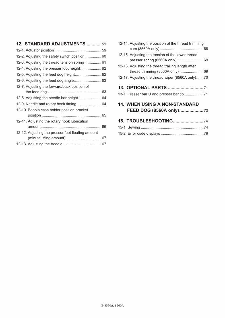
12. STANDARD ADJUSTMENTS ............59 12-1. Actuator position............................................. 59 12-2. Adjusting the safety switch position................ 60 12-3. Adjusting the thread tension spring................ 61 12-4. Adjusting the presser foot height.................... 62 12-5. Adjusting the feed dog height......................... 62 12-6. Adjusting the feed dog angle.......................... 63 12-7. Adjusting the forward/back position of
the feed dog.................................................... 63 12-8. Adjusting the needle bar height...................... 64 12-9. Needle and rotary hook timing ....................... 64 12-10. Bobbin case holder position bracket
position ......................................................... 65 12-11. Adjusting the rotary hook lubrication
amount.......................................................... 66 12-12. Adjusting the presser foot floating amount
(minute lifting amount) .................................. 67 12-13. Adjusting the treadle..................................... 67
12-14. Adjusting the position of the thread trimming cam (8560A only)..........................................68
12-15. Adjusting the tension of the lower thread presser spring (8560A only)..........................69
12-16. Adjusting the thread trailing length after thread trimming (8560A only) .......................69
12-17. Adjusting the thread wiper (8560A only).......70
13. OPTIONAL PARTS ............................71 13-1. Presser bar U and presser bar tip...................71
14. WHEN USING A NON-STANDARD FEED DOG (8560A only)...................73
15. TROUBLESHOOTING........................74 15-1. Sewing ............................................................74 15-2. Error code displays .........................................79
Z-8550A, 8560A
1. NAMES OF MAJOR PARTS
1
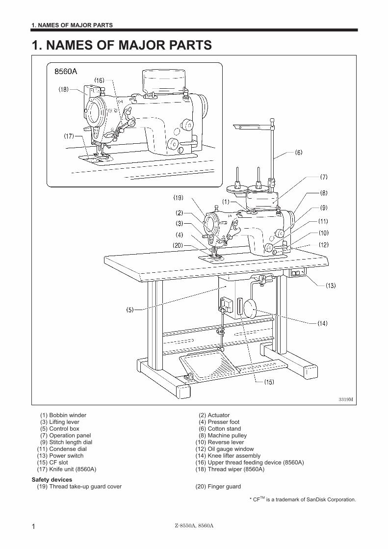
1. NAMES OF MAJOR PARTS
(1) Bobbin winder (2) Actuator (3) Lifting lever (4) Presser foot (5) Control box (6) Cotton stand (7) Operation panel (8) Machine pulley (9) Stitch length dial (10) Reverse lever (11) Condense dial (12) Oil gauge window (13) Power switch (14) Knee lifter assembly (15) CF slot (16) Upper thread feeding device (8560A) (17) Knife unit (8560A) (18) Thread wiper (8560A)
Safety devices (19) Thread take-up guard cover (20) Finger guard
* CFTM is a trademark of SanDisk Corporation.
3319M

Z-8550A, 8560A
2. MACHINE SPECIFICATIONS
2
2. MACHINE SPECIFICATIONS
8550A 8560A 0 A 4
Thread trimmer - - � Upper thread feeding device - - � Back tack/condense device *1 - � � Thread wiper - - �
8550A 8560A -031, -A31 -431 Use For light-weight materials-For medium- weight materials Max. stitch length 2.0 mm *2 Max. sewing speed 5,000 rpm *3
Sewing pattern 14 patterns of eight types built-in (Up to 99 different types of custom-made patterns can be added *4)
Max. zigzag width 10 mm (Factory default 8 mm) Thread take-up lever Rotary thread take-up Needle bar stroke 33.3 mm Feed dog height 1 mm
Lifting lever 6 mm Presser foot height Knee lifter 10 mm Presser foot pressure 10-30 N Needle Schmets 134SUK Nm70/10 Motor AC servo motor (4-pole, 450 W)
Power supply Single-phase: 110 V, 220 V, 230 V
3-phase: 220 V, 380 V, 400 V, 415 V Maximum electric power consumption: 400 VA
Control circuit Microprocessor
*1… Used for sewing condensed stitches and backtack stitches. *2… If replacing gauge parts and then changing the maximum feed amount setting, the maximum setting is 5 mm.
(Refer to pp. 18-19 and p. 57.) *3… At the time of shipment from the factory, the maximum sewing speed is set to 4,000 rpm.
If using a sewing speed higher than this, use the memory switches to change the setting. (Ask the place of purchase for details.) Furthermore, the maximum sewing speed may be limited by the type of sewing pattern and the zigzag width. (Refer to page 31.)
*4… The maximum number of custom-made patterns that can be stored is 99 patterns with a total of 49,500 stitches, at 500 stitches or less per pattern. (Custom patterns can be created using the PS-300B (option device) and are saved into the control box using commercially-available CF cards. Ask the place of purchase for details.)

Z-8550A, 8560A
3. SEWING PATTERN TABLE�
3
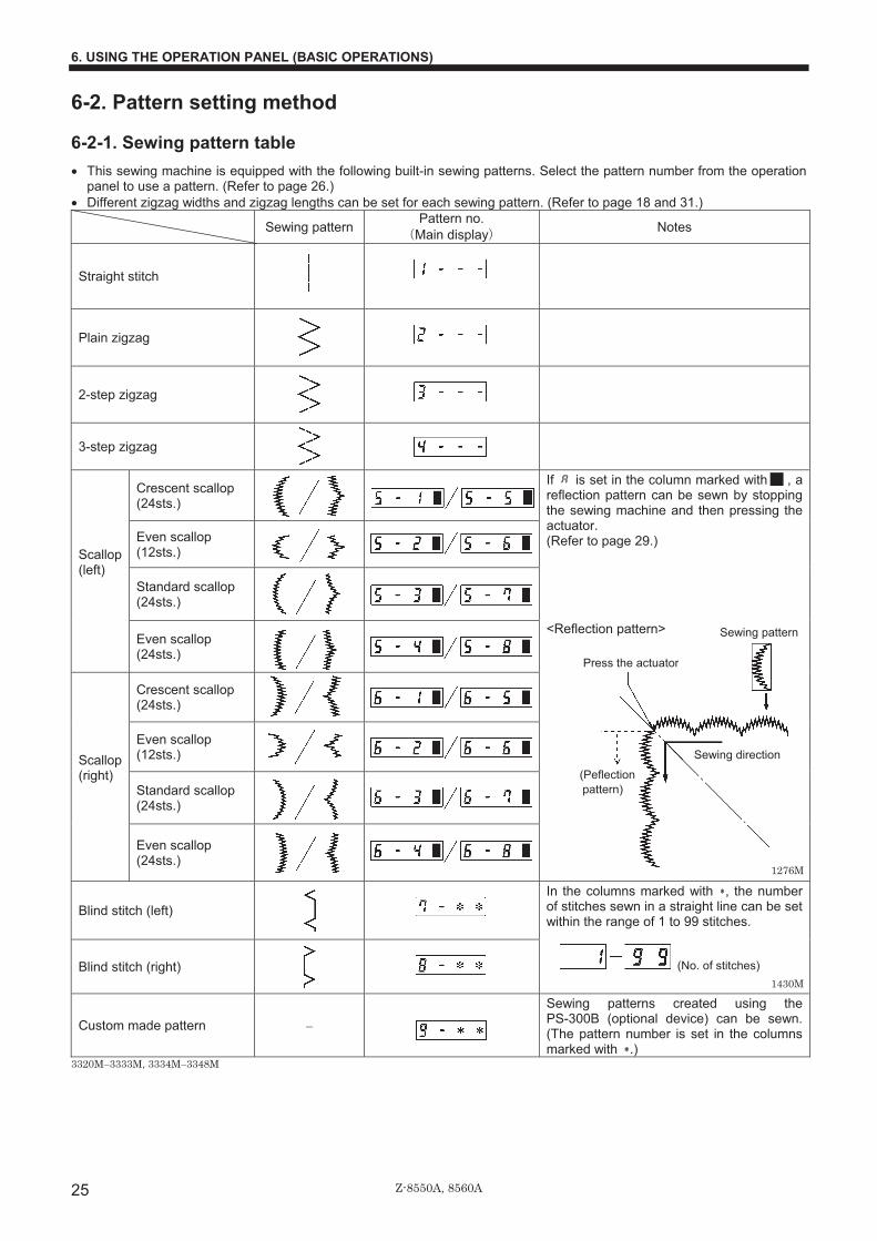
3. SEWING PATTERN TABLE • This sewing machine is equipped with the following built-in sewing patterns. Select the pattern number from the operation
panel to use a pattern. (Refer to page 26.) • Different zigzag widths and zigzag lengths can be set for each sewing pattern. (Refer to page 18 and 31.)
Sewing pattern Pattern no. �Main display� Notes
Straight stitch
Plain zigzag
2-step zigzag
3-step zigzag
Crescent scallop (24sts.)
Even scallop (12sts.)
If is set in the column marked with , a reflection pattern can be sewn by stopping the sewing machine and then pressing the actuator. (Refer to page 29.)
Standard scallop (24sts.)
Scallop (left)
Even scallop (24sts.)
<Reflection pattern>�
Crescent scallop (24sts.)
Even scallop (12sts.)
Standard scallop (24sts.)
Scallop (right)
Even scallop (24sts.)
Blind stitch (left)
Blind stitch (right)
In the columns marked with , the number of stitches sewn in a straight line can be set within the range of 1 to 99 stitches.
(No. of stitches)
Custom made pattern �
Sewing patterns created using the PS-300B (optional device) can be sewn. (The pattern number is set in the columns marked with .)
3320M—3333M 3334M—3348M
(Peflection pattern)
Sewing direction
Press the actuator
Sewing pattern
1430M
1276M

Z-8550A, 8560A
4. INSTALLATION
4
4. INSTALLATION CAUTION
Machine installation should only be carried out by a qualified technician. Contact your Brother dealer or a qualified electrician for any electrical work that may need to be done. The sewing machine weighs approximately 49 kg. The installation should be carried out by two or more people.
Do not connect the power cord until installation is complete. The machine may operate if the treadle is depressed by mistake, which could result in injury. Use both hands to hold the machine head when tilting it back or returning it to its original position. If only one hand is used, the weight of the machine head may cause your hand to slip, and your hand may get caught.
About the machine set-up location • Do not set up this sewing machine near other equipment
such as televisions, radios or cordless telephones, otherwise such equipment may be affected by electronic interference from the sewing machine.
• The sewing machine should be plugged directly into an AC wall outlet. Operation problems may result if extension cords are used.
Carrying the machine • The machine should be carried by the arm by two people as
shown in the illustration.
* Hold the motor cover (A) by hand also so that the pulley does not rotate.
Tilting back the machine head • Hold section (B) with your foot so that the table does not
move, and then push the arm with both hands to tilt back the machine head.
Returning the machine head to the upright position 1. Clear away any tools, etc. which may be near the table
holes. 2. While holding the arm with both hands, gently return the
machine head to the upright position.
3349M
3350M
3351M
3352M

Z-8550A, 8560A
4. INSTALLATION
5
4-1. Table processing diagram • The top of the table should be 40 mm in thickness and should be strong enough to hold the weight and with-stand the
vibration of the sewing machine. • Drill holes as indicated in the illustration below. • Select a method that is easy to carry out for the type of table used.
3354M
Cotton stand hole
Cord hole
Head rest hole Control box mounting hole
<Standard type>
3353M
Cotton stand hole
Cord hole
Head rest hole Control box mounting hole
<Wide type> This type has a wider front/back dimensions at the front of the sewing machine.

Z-8550A, 8560A
4. INSTALLATION
6
4-2. Installation 1. Control box (1) Control box (2) Bolts [4 pcs] (3) Nuts [4 pcs] (4) Spring washers [4 pcs] (5) Washers [4 pcs] 2. Connecting rod (6) Connecting rod (7) Nut
3. Power switch (1) Power switch (2) Screws [2 pcs] (3) Staples [5 pcs]
Secure the power cord (4) in a suitable place depending in the position of the wall outlet.
4. Oil pan (1) Head cushions [4 pcs] (2) Oil pan
3355M
3356M
Operator
3357M
Cord

Z-8550A, 8560A
4. INSTALLATION
7
5. Rubber cushions (1) Rubber cushions [2 pcs] (2) Nails [4 pcs] 6. Knee lifter complying bar (3) Knee lifter complying bar
7. Machine head (1) Hinges [2 pcs] (2) Machine head (3) Head rest NOTE:�
• Tap the head rest (3) securely into the table hole.�
• If the head rest (3) is not pushed in as far as it will go, the machine head will not be sufficiently stable when it is tilted back.
�
�
�
�
�
�
8. Operation panel (1) Operation panel (2) Screws [2 pcs]
(Use for tightening rear cover)
9. Sticker (Remove) (1) Sticker
3360M
3359M
3361M
3358M

Z-8550A, 8560A
4. INSTALLATION
8
10. Cotton stand (1) Cotton stand NOTE:
Securely tighten the nut (4) so that the two rubber cushions (2) and the washer (3) are securely clamped and so that the cotton stand (1) does not move.
11. Knee lifter plate (1) Knee lifter plate (2) Bolt * Loosen the bolt (3) and move the
knee lifter plate (1) to a position where it is easy to use.
<Knee lifter adjustment> 1. Turn the machine pulley so that the feed dog is below the
top of the needle plate.�2. Lower the presser foot (5) by using the lifting lever (4).��
�
�
�
�
�
3. Loosen the nut (6). 4. Turn the screw (8) to adjust so that the amount of play in
the knee lifter (7) is approximately 2 mm when the knee lifter plate (1) is gently pressed.
5. Securely tighten the nut (6). 6. Loosen the nut (9). 7. Turn the screw (10) until the distance between the end of
the screw (10) and the knee lifter (11) is approximately 4 mm.
8. Turn the adjusting screw (10) to adjust so that the presser foot (5) is at the desired position within a distance of 10 mm of the needle plate when the knee liter plate (1) is fully pressed.
9. After adjustment is completed, securely tighten the nut (9).
2098M
3362M
2101M
3789M
Within 10 mm 3790M

Z-8550A, 8560A
4. INSTALLATION
9
4-3. Lubrication
CAUTION Do not connect the power cord until lubrication has been completed, otherwise the machine may operate if the
treadle is depressed by mistake, which could result in injury. Be sure to wear protective goggles and gloves when handling the lubricating oil and grease, so that they do not get into your eyes or onto your skin, otherwise inflammation can result. Furthermore, do not drink the oil or eat the grease under any circumstances, as they can cause vomiting and diarrhea. Keep the oil out of the reach of children.
• The sewing machine should always be lubricated and the oil supply replenished before it is used for the first time, and also after long periods of non-use.
• Use only the lubricating oil (Nisseki Mitsubishi Sewing Lube 10N; VG10) specified by Brother. * If this type of lubricating oil is difficult to obtain, the
recommended oil to use is <Exxon Mobil Essotex SM10; VG10>.
1. Remove the rubber cap (1). 2. Use the accessory oiler (2) to add lubricating oil until
the oil gauge (4) comes to the top reference line of the oil gauge window (3).
NOTE:�• Pour in the lubricating oil slowly while checking the
position of the oil gauge (4). • Do not let the oil gauge (4) go higher than the top
reference line when adding the oil.
3. Replace the rubber cap (1).
* Be sure to add more oil if the oil gauge (4) is below the lower reference line.
3365M
Upper referenceline
Lower reference line

Z-8550A, 8560A
4. INSTALLATION
10
4-4. Connecting the cords
DANGER Wait at least 5 minutes after turning off the power switch and disconnecting the power cord from the wall outlet
before opening the face plate of the control box. Touching areas where high voltages are present can result in severe injury.
�
CAUTION Contact your Brother dealer or a qualified electrician for any electrical work that may need to be done.
Do not connect the power cord until all cords have been connected. The machine may operate if the treadle is depressed by mistake, which could result in injury. sure to connect the ground. If the ground connection is not secure, you run a high risk of receiving a serious electric shock, and problems with correct operation may also occur.
4-4-1. Opening the control box cover (1) Screw [6 pcs: With washer] (2) Cover
4-4-2. Connecting the cords 1. Sewing machine cords (1) Repeat cable tie
3366MLoosen
3367M
<Removal>
<Securing>
Press the tab.
Cords

Z-8550A, 8560A
4. INSTALLATION
11
Connector P.C. board indication Cord clamp (2) 4-pin motor connector Outside of control box (3) 5-pin zigzag motor connector P5 PM (10) (4) 7-pin head detector unit connector P6 HEAD-M (10) (12) (14) (15) (5) 14-pin machine connector P19 MACHINE (11) (13) (6) 14-pin encoder connector P13 ENC (10) (12) (7) 8-pin operating panel connector P21 PANEL (10) (12) (14) (15) (8) 5-pin zigzag motor encoder connector P3 NDL_ENC (10) (9) 3-pin DC fan connector (oil pan) P32 FAN2 (11) (13) (14) (15)
2. Closing the cord presser plate (1) Cord presser plate
NOTE:�• Loosen the cables outside the control box without
stretching them too much inside the control box. • If the cord presser plate (1) is not closed firmly, dust
will get inside the control box and may cause problems.
3369M
Push in securely until the tabs (16) engage.
<Removal> <Securing>
Press the tab.
Insert firmly until a click is heard.
Ground symbol
3368M
Close
Tighten
Loosen as much as possible.

Z-8550A, 8560A
4. INSTALLATION
12
3. Closing the cover (1) Screw [6 pcs: With washer] (2) Cover
4. Power cord (1) Power cord
<For single-phase specifications> Insert the power cord plug (2) into a wall outlet.
<For three-phase specifications> 1. Attach an appropriate plug to the
power cord (1). (The green and yellow wire is the ground wire.)
2. Insert the plug into a properly-grounded AC power supply.
NOTE:�Do not use extension cords, otherwise machine operation problems may result.
5. Ground wire (1) Ground wire (2) Spring washer [2 pcs] (3) Plain washer[2 pcs] (4) Screw [2 pcs]
3370M
3371M
Tighten
<Single-phase> <Three-phase>
Green and yellowwire (ground wire)
3372M
Ground symbol
Oil pan
Ground symbol

Z-8550A, 8560A
4. INSTALLATION
13
4-5. Test operation (Operating the treadle)
CAUTION Do not touch any of the moving parts or press any objects against the machine while sewing, as this may result in
personal injury or damage to the machine.
4-5-1. Turning on the power • Release the treadle when turning on the power.
(If the treadle is depressed, “Err 95” will appear in the main display. At this time, “PoFF” will appear when you take your foot off the treadle, so turn the power off and back on again.)
• After the power is turned on, the subsequent operation of the sewing machine will vary according to the needle bar position at that time.
<If the needle bar is at the needle up stop position> Turn on the POWER switch (1). The buzzer will sound for about one second, and then the needle bar will move horizontally to the sewing start position. Sewing will then be possible.
�
�
�
�
�
�
�
�
�
�
�
<If the needle bar is not at the needle up stop position> 1. Turn on the POWER switch(1). The buzzer will sound for
about one second, and then “UP” will appear in the main display (2).
2. Turn the machine pulley slowly to move the needle bar to the needle up stop position. (Align the reference line (3) on the sewing machine pulley within the indent (4) in the motor cover.) The needle bar will then move horizontally to the sewing start position and sewing will then be possible.
�
�
�
�
�
�
�Panel setting status�• The panel setting status will be the same status that was active at the time the power was last turned off. • The pattern number will appear in the main display while the buzzer is sounding, and after that the zigzag width and zigzag
base line position will appear.��
�
2114M
2114M 3374M
Illuminate
Illuminate
3373M

Z-8550A, 8560A
4. INSTALLATION
14
4-5-2. Operating the treadle 1. When the treadle (3) is gently depressed to position (B),
low-speed sewing is carried out. 2. If it is then depressed as far as (C), high-speed sewing is
carried out. 3. When the treadle (3) is pressed forward and then back to
the neutral position (A), the needle will stop below the needle plate (when needle down stop mode has been set). If the needle bar has been set to stop in the needle up position, the needle will stop at a position above the needle plate (needle up stop position).
4. When the treadle (3) is depressed all the way to position (D) (or if the treadle (3) is depressed to position (D) and then returned to the neutral position (A)), the mechanism will sew half a stitch or one stitch, and then the needle bar will stop at the needle up stop position. (With the 8560A, the thread will be trimmed at this point.) Furthermore, no needle zigzagging will be carried out at this time.
2116M
2117M

Z-8550A, 8560A
5. PREPARATION BEFORE SEWING
15
5. PREPARATION BEFORE SEWING 5-1. Installing the needle
CAUTION Turn off the power switch before installing the needle.
The machine may operate if the treadle is depressed by mistake, which could result in injury.
1. Turn the machine pulley to move the needle bar to its highest position.
2. Loosen the screw (1). 3. Insert the needle (2) in a straight line as far as it will go,
making sure that the long groove on the needle is toward the front, and then securely tighten the screw (1).
�
5-2. Removing the bobbin case
CAUTION Turn off the power switch before removing the bobbin case.
The machine may operate if the treadle is depressed by mistake, which could result in injury.
1. Turn the machine pulley to raise the needle until it is above the needle plate.�
2. Pull the latch (1) of the bobbin case upward and then remove the bobbin case.�
3. The bobbin (2) will come out when the latch (1) is released.�
�* Use bobbins (2) made of light alloy as specified by
BROTHER. �
�
�
�
�
�
�
�
8560A There is an anti-spin spring (3) inside the bobbin case. The anti-spin spring (3) prevents the bobbin from racing at times such as during thread trimming.
�
Front
Long groove
3378M
3792M3791M
3818M
<8560A>
3793M

Z-8550A, 8560A
5. PREPARATION BEFORE SEWING
16
5-3. Winding the lower thread
CAUTION Do not touch any of the moving parts or press any objects against the machine while winding the lower thread, as
this may result in personal injury or damage to the machine.
1. Turn on the power switch.�2. Place the bobbin (1) onto the bobbin winder shaft (2).�3. Wind the thread several times around the bobbin (1) in
the direction indicated by the arrow.�4. Push the bobbin presser arm (3) toward the bobbin(1).�5. Raise the presser foot with the lifting lever.�6. Depress the treadle. Lower thread winding will then start.�7. Once winding of the lower thread is completed, the
bobbin presser arm (3) will return automatically.�8. After the thread has been wound on, remove the bobbin
and cut the thread with the knife (4). * Loosen the screw (5) and move the bobbin presser (6) to
adjust the amount of thread wound onto the bobbin.
NOTE:�The amount of thread wound onto the bobbin should be a maximum of 80 % of the bobbin capacity.
5-4. Installing the bobbin case
CAUTION Turn off the power switch before installing the bobbin case.
The machine may operate if the treadle is depressed by mistake, which could result in injury.
1. Turn the sewing machine pulley to align the reference line on the pulley with the indent in the motor cover.�
2. Hold the bobbin so that the thread spools out counterclockwise, and place the bobbin into the bobbin case.�
3. Pass the thread through slot (1) and hook it under the tension spring (2).�
4. Pass the thread back through the slot (3) and then pull it out from the thread guide (4).
A and B on the thread guide (4) (guide to identification) A Normally A should be used.
BThe amount of lower thread feeding-out is greater than for A, so this is ideal for extremely stretchy materials and medium-weight materials.
5. Check that the bobbin rotate counterclockwise when the thread is pulled out.�
6. While holding the latch (5) of the bobbin case, insert the bobbin case into the rotary hook.
3381M
Less thread
More thread
3382M
3380M
2123M

Z-8550A, 8560A
5. PREPARATION BEFORE SEWING
17
5-5. Threading the upper thread
CAUTION Turn off the power switch before threading the upper thread.
The machine may operate if the treadle is dep ressed by mistake, which could result in injury. If the actuator is pressed by mistake when using the correction sewing function, the needle will move in a zigzag motion while the machine is operating, and injury may result.
Turn the sewing machine pulley to align the reference line (1) on the pulley with the indent (2) in the motor cover (needle up stop position). This will make threading easier and it will prevent the thread from coming out at the sewing start.
3794M
Wind around once.
Upper thread feeding device
Actuator
Leave a 50 mm thread leader.

Z-8550A, 8560A
5. PREPARATION BEFORE SEWING
18
5-6. Adjusting the stitch length Turn the stitch length dial (1) until the desired stitch length number is aligned with the index mark (2) above the dial. * The larger the number, the longer the stitch length will be. * The numbers on the dial are for use as a guide. The
length of the finished stitches may vary depending on the type and thickness of material being sewn. Adjust while looking at the finished stitches.
If the stitch length dial (1) is turned to a setting greater than 2.5 * In this case, replace gauge parts such as the feed dog
with parts for using with a feed amount of more than 2.0 mm. In addition, change the maximum feed amount setting while referring to page 57, and then adjust the stitch length dial (1) as described below.
1. Turn the stitch length dial (1) all the way to “2.5”. 2. After this, push the left lever (3) while turning the stitch
length dial (1) so that it can be turned a second time. When the stitch length dial (1) is turned a second time, the settings will be those on the inside of the scale (3�5).
* When turning the dial from a larger number to a smaller
number, it can be turned to the second time setting without pushing the left lever (3).
Setting for 1st turnSetting for 2nd turn
3384M
3470M(Zigzag width)
Stitch length

Z-8550A, 8560A
5. PREPARATION BEFORE SEWING
19
5-7. Backtacking � Backtack stitches with short stitch lengths can be sewn
easily during sewing just by pressing the reverse lever (1). This is useful for preventing fraying of the seam at the sewing end.
� Before sewing, turn the condense dial (2) to the left or right to set the stitch length for these shorter backtack stitches.
If using the 8560A, 8550A-A31 The actuator (3) can be used instead of the reverse lever (1).
< Sewing condensed stitches > � When the condense dial (2) is set to a positive number,
backtack stitches with a stitch length that matches the dial setting will be sewn in the normal sewing direction while the reverse lever is pressed.
� If the condense dial (2) is set to “0”, backtack stitches will be sewn without the material being fed while the reverse lever is pressed.
< Backtacking > When the condense dial (2) is set to a negative number, backtack stitches with a stitch length that matches the dial setting will be sewn in the reverse sewing direction while the reverse lever (1) is pressed.
* The numbers on the dial are for use as a guide. The length of the finished stitches may vary depending on the type and thickness of material being sewn. Adjust while looking at the finished stitches.
When the condense dial (2) is set to a number from -2 to -5 In this case, replace gauge parts such as the feed dog with parts for using with a feed amount of more than 2.0 mm. In addition, change the maximum feed amount setting while referring to page 57, and then adjust the condense dial (2) to a number from –2 to –5.
3385M
3386M
3387M
(Sewing direction)
When reverse lever is pressed
When reverse lever is pressed

Z-8550A, 8560A
5. PREPARATION BEFORE SEWING
20
5-8. Using the knee lifter The presser foot (2) can be raised by pressing the knee lifter plate (1).
5-9. Using the thread wiper (8560A only) Press the thread wiper switch (1) to the side. If this is done, the thread wiper (2) will operate after the thread is trimmed.
2209M
3388M
3795M
3796M

Z-8550A, 8560A
6. USING THE OPERATION PANEL (BASIC OPERATIONS)
21
6. USING THE OPERATION PANEL (BASIC OPERATIONS)
6-1. Names and functions • The operation panel keys cannot be operated while sewing is in progress.
Check the key selections and pattern settings before starting sewing.
Z-ST�8550A-031�
Z-40�8550A-A31, 8560A�
[Main display (3)]
Power indicator
3390MPower indicator
3391M
3392M

Z-8550A, 8560A
6. USING THE OPERATION PANEL (BASIC OPERATIONS)
22
The power indicator illuminates when the power switch is turned on. (1) Sewing speed control display
This shows the sewing speed when the treadle is depressed to the maximum amount. • If all bars are illuminated, it indicates that the maximum speed can be set. • If all bars are switched off, it indicates the minimum speed (220 rpm).
(2) Sewing speed control keys
These keys let you adjust the sewing speed that is used when the treadle is depressed to the maximum amount. The sewing speed can also be adjusted while sewing is in progress. • When the key is pressed, the sewing speed becomes faster. • When the key is pressed, the sewing speed becomes slower.
(3) Main display
Shows the zigzag width and zigzag base line position when normal sewing is in progress, Shows the current setting values for the zigzag width, zigzag base line position and the type of scallop stitch. • In start backtack display, AB illuminates and the number of stitches for A and B are
displayed. • In end backtack display, CD illuminates and the number of stitches for C and D are
displayed. • In continuous backtack display, ABCD illuminates and the number of stitches for A, B, C
and D are displayed. • In fixed-stich sewing/label sewing display, EF illuminates and the number of stitches for
E and F are displayed. If the number of stitches for F is “0”, fixed stitch sewing is carried out, and if it is any other setting, label sewing is carried out.
(4) Zigzag width/Zigzag base line position key
This key lets you change the zigzag width and move the sewing pattern to the left and right. • When this key is pressed, the indicator illuminates, and the currently-set zigzag width is
displayed in the four left columns and the zigzag base line position is displayed in the four right columns.
• A zigzag width display of [5.0 ] means that the zigzag width is 5.0 mm. • A zigzag base line position display of [ L2.0] means that the pattern is moved 2.0 mm
to the left, and a display of [ r2.0] means that the pattern is moved 2.0 mm to the right.
(5) Zigzag stop position key
This key is used to set the needle stop position to the left or the right of the zigzag when the sewing machine stops.�• Each time the zigzag stop position key i is pressed, the indicator display changes in the
order • • (OFF). • When is lit: the needle always moves to the left of the zigzag when the sewing
machine stops. • When is lit: the needle always moves to the right of the zigzag when the sewing
machine stops. • When both indicators are off, the needle stops at its current position when the sewing
machine stops.
(6) Lower thread counter display
This shows the lower thread counter value. • The counter is reduced by “1” for every ten stitches sewn.
(7) Lower thread counter keys
These keys are used to set the initial value for the lower thread counter.�Setting is only possible immediately after the lower thread counter has been reset.�• When the key is pressed, the value increases, and when it is held down, the value
increases more quickly. • When the key is pressed, the value decreases, and when it is held down, the value
decreases more quickly. �
2148M
2149M 2150M 2151M
3393M
2154M
3394M
3395M 3396M 3397M
2155M 2168M 2169M

Z-8550A, 8560A
6. USING THE OPERATION PANEL (BASIC OPERATIONS)
23
(8) RESET key
This key is used to return the lower thread counter to its initial value and to cancel warning conditions.�• If this key is pressed when the lower thread counter value is “0” or less, the value will
return to the initial value. • If this key is pressed for 2 seconds or more while the lower thread counter value is “1” or
more, the value will return to the initial value. (9) Half stitch key
When the sewing machine is stopped, the needle bar can be moved up and down by pressing this key.
(10) Plain zigzag key
When this key is pressed so that the indicator illuminates, a plain zigzag pattern is selected.�• When a plain zigzag pattern has been selected, the indicator illuminates.
(11) 3-step zigzag key
When this key is pressed so that the indicator illuminates, a 3-step zigzag pattern is selected. • When a 3-step zigzag pattern has been selected, the indicator illuminates.
(12) Scallop key
When this key is pressed so that the indicator illuminates, a scallop pattern is selected.�• Illumination switches between the left and right indicators each time this key is pressed. • When a scallop pattern has been selected, one of the indicators (left or right) illuminates.
(13) Straight stitch key
When this key is pressed so that the indicator illuminates, a straight stitch pattern is selected.�• When a straight stitch pattern has been selected, the indicator illuminates.�
(14) 2-step zigzag key�
When this key is pressed so that the indicator illuminates, a 2-step zigzag pattern is selected. • When a 2-step zigzag pattern has been selected, the indicator illuminates.
(15) Blind stitch key
When this key is pressed so that the indicator illuminates, a blind stitch pattern is selected.• Illumination switches between the left and right indicators each time this key is pressed. • When a blind stitch pattern has been selected, one of the indicators (left or right)
illuminates. (16) CF key�for option�
• This key is disabled when there is no custom pattern available. • If a custom pattern is available, the indicator will illuminate when this key is pressed and
the custom pattern will be selected. • When a custom pattern has been selected, the indicator illuminates.
(17) Setting keys
These keys are used to make settings for zigzag width, zigzag base line position and scallop stitching. [Z-40 only]: In addition, they are also used to make the settings for the number of backtack
stitches A, B, C and D and the number of fixed stitches E and F. • When the key is pressed, the value increases. • When the key is pressed, the value decreases.
3398M
2156M
3399M
3400M
3401M
3402M
3403M
3404M
3405M
2137M 2138M 2139M

Z-8550A, 8560A
6. USING THE OPERATION PANEL (BASIC OPERATIONS)
24
(18) Start backtack key [Z-40 only]
When this key is pressed so that the indicator illuminates, the number of start backtack stitches (0�99) in the A and B stitch number displays is sewn.
(19) End backtack key [Z-40 only]
When this key is pressed so that the indicator illuminates, the number of end backtack stitches (0�99) in the C and D stitch number displays is sewn. When the treadle is depressed backward, the end backtack stitches are sewn and then the thread is trimmed automatically. • If the treadle has not yet been depressed backward, the end backtack function can be
set to ON, the number of stitches can be changed and the function can be set back to OFF.
(20) Continuous backtack key [Z-40 only]
When this key is pressed so that the indicator illuminates, the number of backtack stitches (0�99) in the A, B, C and D stitch number displays is sewn continuously. After the sewing machine sews a full cycle of stitches set by A, B, C and D, the thread is trimmed automatically.
(21) Fixed stitch/name label key [Z-40 only]
When this key is pressed so that the indicator illuminates while the number of stitches set for F is “0”, the number of stitches set for E (1�250) that appears in the main display is sewn, and then sewing stops automatically.�When this key is pressed so that the indicator illuminates while the number of stitches set for F is something other than “0”, fixed stitch sewing is carried out repeatedly for the number of stitches set for E and F (1�250) that appears in the main display .
(22) AUTO key [Z-40 only]
This can only be used to make settings together with continuous backtack key (20) and fixed stitch/name label key (21).�• When this key is pressed so that the indicator illuminates, the set number of stitches
(start or end backtack stitches, fixed stitches or thread trimming) are sewn automatically simply by depressing the treadle once.
(23) TEST key
This key is used when adjusting the needle and rotary hook timing. icon�• When the TEST key is pressed, the TEST icon (25) illuminates. In this condition, the
sewing machine motor will not operate even if the treadle is depressed. Needle zigzag movement can be carried out by turning the machine pulley by hand.
• If the TEST key is pressed once more, the icon (25) will switch off and the sewing machine will return to the normal state of operation.
(24) Thread trimming lock key [Z-40 only]
When this key is pressed so that the indicator illuminates, the sewing machine stops in the needle up position without thread trimming being carried out even if the treadle is depressed backward. • If the AUTO key (22) is illuminated, the sewing machine stops in the needle up position
without thread trimming being carried out after the set number of stitches have been sewn.
(25) TEST icon
This illuminates when the TEST key (23) is pressed.
(26) Zigzag base line position icon
This illuminates when the zigzag base line position is being displayed in the main display.
(27) Backtack zigzag width icon
This illuminates when the backtack zigzag width is being displayed in the main display .
(28) Zigzag width icon
This illuminates when the zigzag width is being displayed in the main display .�
3406M
3407M
2142M
3408M
2147M
3409M
2152M
3410M
3411M
3412M
3413M
Z-8550A, 8560A
6. USING THE OPERATION PANEL (BASIC OPERATIONS)
25
6-2. Pattern setting method
6-2-1. Sewing pattern table • This sewing machine is equipped with the following built-in sewing patterns. Select the pattern number from the operation
panel to use a pattern. (Refer to page 26.) • Different zigzag widths and zigzag lengths can be set for each sewing pattern. (Refer to page 18 and 31.)
Sewing pattern Pattern no. �Main display� Notes
Straight stitch
Plain zigzag
2-step zigzag
3-step zigzag
Crescent scallop (24sts.)
� �
Even scallop (12sts.)
� �
If is set in the column marked with , a reflection pattern can be sewn by stopping the sewing machine and then pressing the actuator. (Refer to page 29.)
Standard scallop (24sts.)
� �
Scallop (left)
Even scallop (24sts.)
<Reflection pattern>�
Crescent scallop (24sts.)
Even scallop (12sts.)
Standard scallop (24sts.)
Scallop (right)
Even scallop (24sts.)
Blind stitch (left)
Blind stitch (right)
In the columns marked with , the number of stitches sewn in a straight line can be set within the range of 1 to 99 stitches.
(No. of stitches)
Custom made pattern �
Sewing patterns created using the PS-300B (optional device) can be sewn. (The pattern number is set in the columns marked with .)
3320M�3333M, 3334M�3348M
1276M
1430M
(Peflection pattern)
Sewing direction
Press the actuator
Sewing pattern

Z-8550A, 8560A
6. USING THE OPERATION PANEL (BASIC OPERATIONS)
26
6-2-2. Setting the sewing pattern Press the sewing pattern select keys ([1] to [7] in the illustration left) to select the sewing pattern. The indicator for the key that was pressed will illuminate and the pattern number that has been set for that key will appear in the main display. * When a sewing pattern has been set, be sure to set the
zigzag width. (Refer to page 31.)
[1] Plain zigzag �
�
�
�
�
�
�
�
[2] 2-step zigzag��
�
�
�
�
�
�
�
[3] 3-step zigzag �
�
�
�
�
�
�
�
[4] Straight stitching��
�
�
�
�
�
�
�
�Note:�
If the needle bar is at the needle up stop position, the needle bar will move to the sewing start position when the sewing pattern settings are changed. If the needle bar is not at the needle up stop position, the needle bar will move to the sewing start position after it next moves to the needle up stop position.
3417M
3415M
3418M
3416M
3414M

Z-8550A, 8560A
6. USING THE OPERATION PANEL (BASIC OPERATIONS)
27
[5] Blind stitching If selecting blind stitching, set the number of stitches to be sewn in a straight line.
1 Setting the sewing pattern When the blind stitch key is pressed, the indicator in the top-left corner of the key will illuminate and “left” blind stitching will be selected.
�
�
�
�
�
�
�
�If the key is pressed once more, the indicator in the top-right corner of the key will illuminate and “right” blind stitching will be selected.
�
�
�
�
�
�
�
� (The blind stitch selection switches between “left” and “right” each time the key is pressed.)
�* If no pattern number appears in the main display when blind
stitching is selected (an indicator in the blind stitch key is illuminated), the selected pattern number will appear when this key is pressed.
NOTE:�
If the needle bar is at the needle up stop position, the needle bar will move to the sewing start position when the sewing pattern settings are changed. If the needle bar is not at the needle up stop position, the needle bar will move to the sewing start position after it next moves to the needle up stop position.
2 Setting the number of straight stitches Use the keys (2) to set the number of straight stitches (1) appearing in the main display . (For example, if the number of straight stitches is 5, set to “7-5”, and if the number of straight stitches is 10, set to “7-10”.
�
3419M
3422M 3423M
3420M
3421M
Example: Pattern number [ 7-** ]
Example: [ 7-5 ]
5 stitches 10 stitches
Example: [ 7-10 ]
Z-8550A, 8560A
6. USING THE OPERATION PANEL (BASIC OPERATIONS)
28
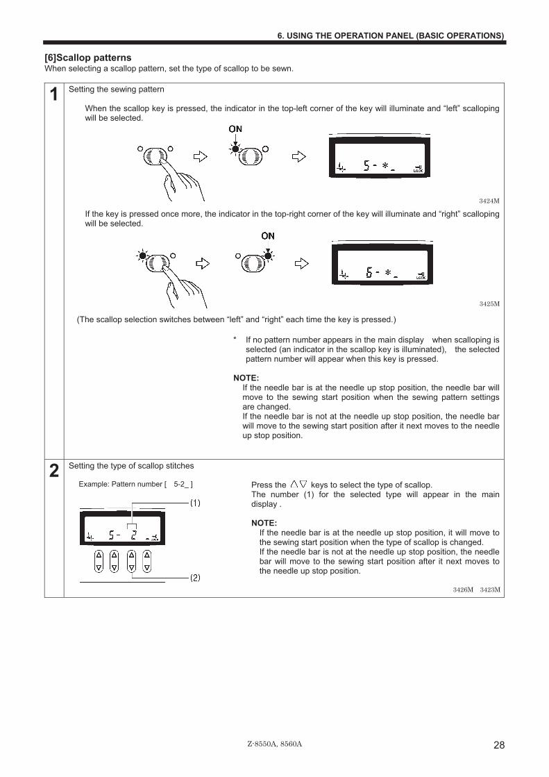
[6]Scallop patterns When selecting a scallop pattern, set the type of scallop to be sewn.
1 Setting the sewing pattern When the scallop key is pressed, the indicator in the top-left corner of the key will illuminate and “left” scalloping will be selected.
�
�
�
�
�
�
�
�If the key is pressed once more, the indicator in the top-right corner of the key will illuminate and “right” scalloping will be selected.
�
�
�
�
�
�
�
�(The scallop selection switches between “left” and “right” each time the key is pressed.)
�* If no pattern number appears in the main display when scalloping is
selected (an indicator in the scallop key is illuminated), the selected pattern number will appear when this key is pressed.
NOTE:�
If the needle bar is at the needle up stop position, the needle bar will move to the sewing start position when the sewing pattern settings are changed. If the needle bar is not at the needle up stop position, the needle bar will move to the sewing start position after it next moves to the needle up stop position.
2 Setting the type of scallop stitches Press the keys to select the type of scallop. The number (1) for the selected type will appear in the main display .
NOTE:�
If the needle bar is at the needle up stop position, it will move to the sewing start position when the type of scallop is changed. If the needle bar is not at the needle up stop position, the needle bar will move to the sewing start position after it next moves to the needle up stop position.
�
�
�
�
�
3424M
3425M
Example: Pattern number [ 5-2_ ]
3426M 3423M

Z-8550A, 8560A
6. USING THE OPERATION PANEL (BASIC OPERATIONS)
29
<Reflection patterns> Scallop patterns can be reflected while sewing.�
When selecting the type of scallop, press the or key (1) so that “A” (2) is displayed. (If you press the or key (1) once more, the “A” display will disappear and the reflection pattern setting will be cancelled.)
�
�
�
�
�
�
�
<Sewing reflection patterns>
1 While sewing, stop the sewing machine at the point where
you would like the reflection pattern to start being sewn.�
2
Press the actuator (3). [AAAA ] will appear in the main display (4) and the pattern sewn from that point will be a reflection pattern. * If you make a mistake and press the actuator (3) at the
wrong time, press the actuator (3) once more to clear the [AAAA ] display.
�
3
Reflection patterns can be sewn.�
�NOTE:�
• If the pattern number selected is [ 5-*A ] or [ 6-*A ], correction sewing using the actuator (3) will not be possible. • If the pattern number selected is [ 5-*_ ] or [ 6-*_ ], reflection patterns cannot be sewn, but correction sewing using the
actuator t will be possible instead. (Refer to page 40.) �
�
�
3427M 2138M 2139M
Example: Pattern number [ 5-1A ]
[ 5-1A ] When material is rotated 90° anda reflection pattern is sewn
(Reflection) Sewing direction
[ 5-1_ ] with no reflection
Sewing direction
3428M
2159M

Z-8550A, 8560A
6. USING THE OPERATION PANEL (BASIC OPERATIONS)
30
[7] T stitch Memory switch settings can be used to sew T stitches easily. (Refer to the service manual or ask the place of purchase for details on the memory switch setting method.)
[8] Custom-made patterns (option) For details, refer to the place of purchase. * Up to a maximum of 99 sewing patterns can be added by creating sewing patterns using the PS-300B (option).
(A maximum of 49,500 stitches can be stored, with each pattern having a maximum of 500 stitches.)
�
�
�
�
�
�
�
�
�
�
�
�
3429M
Example:
Pattern number
3595M

Z-8550A, 8560A
6. USING THE OPERATION PANEL (BASIC OPERATIONS)
31
6-2-3. Setting the zigzag width Set the zigzag width after selecting the pattern number. The zigzag width is defined as the distance between the leftmost needle drop point and the rightmost needle drop point. If the zigzag width is increased or reduced, the width of the sewing pattern is also increased or reduced by the same proportion. * The zigzag width will be automatically set to [0.0 ] only when the straight stitch has been selected as the sewing pattern. <Setting method> �
�
�
�
�
�
�
�
�
�
�
�Press the selection keys (3) to change the zigzag width. The standard setting range for the zigzag width is set to 0 - 8 mm at the factory.
�NOTE:�
• The zigzag width cannot be changed if the indicator is not illuminated, even when the zigzag width is being displayed in the main display . When changing the zigzag width, press the zigzag width/zigzag base line position key so that the indicator is illuminated, and then change the setting.
• If the needle bar is at the needle up stop position, the needle bar will move to the sewing start position when the zigzag width is changed. If the needle bar is not at the needle up stop position, the needle bar will move to the sewing start position after it next moves to the needle up stop position.
Sewing speed limits The sewing speed is limited by the amount of zigzag movement. Accordingly, the actual sewing speed may differ from the setting speed for the following sewing patterns as a result of the zigzag width setting. The speeds are controlled automatically as shown below. * For straight stitches and 3-step zigzag stitches, the sewing speed is not limited by the zigzag width setting. For plain zigzag and blind stitch�
Zigzag width 0-4 mm 4.1-5.0 mm 5.1-6.0 mm 6.1-9.0 mm 9.1-10.0 mm Sewing speed 5000 rpm 4000 rpm 3500 rpm 3000 rpm 2500 rpm
For 2-step zigzag�
Zigzag width 0-8 mm 8.1-10.0 mm Sewing speed 5000 rpm 4000 rpm
2162M
The currently-set zigzag widthwill appear in the main display(1). (For example, [5.0 ] represents 5.0 mm.) * When the zigzag width is
being displayed, the zigzagwidth icon (2) will illuminate.
Zigzag width
Zigzag width
Zigzag width
Zigzag width
1336M1335M
3430M3423M

Z-8550A, 8560A
6. USING THE OPERATION PANEL (BASIC OPERATIONS)
32
6-2-4. Setting the zigzag base line position The zigzag base line is the “center” of the zigzag stitch, or in other words, it is like a center line drawn through the sewing pattern. By moving the zigzag base line position, you can move the sewing pattern to the left and right within the maximum range for the pattern width. <Setting method> �
�
�
�
�
�
�
�
�
�
�
�Press the selection keys (3) to change the zigzag base line position. � If changing the setting from [ 0] first change the numerals, and then set “L” or “r”.
Use the 2nd keys (4) from the right to change the L and r settings. �NOTE:�• The zigzag base line position cannot be changed if the indicator is not illuminated, even when the zigzag base line position
is being displayed in the main display . When changing the zigzag base line position, press the zigzag width/zigzag base line position key so that the indicator is illuminated, and then change the setting.
• If the needle bar is at the needle up stop position, the needle bar will move to the sewing start position when the zigzag base line position is changed. If the needle bar is not at the needle up stop position, the needle bar will move to the sewing start position after it next moves to the needle up stop position.
Relationship between zigzag base line position and zigzag width (when the maximum zigzag width is 8 mm)
By way of example, consider a sewing pattern (Figure A) with a zigzag base line position set to [ 0] and a zigzagwidth set to [4.0 ]. If the zigzag base line position is set to [ L2.0], the pattern will be moved over toward the left edge (Figure B). The sewing pattern cannot move any further to the left even if a larger setting is made. (Even if the zigzag base line position is set to [ L3.0], the sewing pattern position will be the same as if the setting had been [ L2.0]. (Figure C.) However, in this case, if the zigzag width is set to [2.0 ], a sewing pattern such as that shown in Figure D will be produced.
3432M 3423M
The currently-set zigzag base lineposition will appear in the maindisplay (1). (For example, [ L2.0] indicatesthat the pattern position is 2.0 mmto the left, and [ r2.0] indicatesthat the pattern position is 2.0 mmto the right.) * When the zigzag base line
position is being displayed, thezigzag base line position icon.
Maximum zigzag width (8 mm) (8 mm) Zigzag width
Zigzag width
Zigzag width
Zigzag width
Base line Base line Base line Base line2 mm to the left
3431M1338MBase line 0
Base line 0
Base line [ L2.0]
Zigzag width 3 mm
Example
1341MBase line
Zigzag width

Z-8550A, 8560A
6. USING THE OPERATION PANEL (BASIC OPERATIONS)
33
6-2-5. Setting the zigzag stop position When the plain zigzag, 2-step zigzag, 3-step zigzag or scallop sewing patterns are selected, you can set whether the needle stops when it is at the right side or the left side of the sewing pattern. (If the right stopping has been set, the needle stop position will be the position shown by � in the illustration below.) * When the straight stitch, blind stitch or custom-made sewing patterns have been selected, the zigzag stop position setting
is ignored. <Sewing machine operation when sewing stops> When right stopping or left stopping is set, the sewing machine will keep running until the set position is reached, even if the treadle is returned to the neutral position or depressed backward. • For plain zigzag, 2-step zigzag and 3-step zigzag, the needle will stop at the stitch furthest to the right if right stopping has
been set, or at the stitch furthest to the left if left stopping has been set. • For the scallop sewing pattern, the needle will stop at the next right-side stitch if right stopping has been set, or at the next
left-side stitch if left stopping has been set. <Setting method> �
�
�
�
�
�
�
�
�
�
�
<Sewing start position after the treadle is depressed backward> When right stopping has been set, sewing starts from the right side. When left stopping has been set, sewing starts from the left side. • If the needle stops in the needle down stop position, the needle will be raised to the needle up stop position when the
treadle is depressed backward. (The workpiece can then be changed.) The next sewing operation starts from the same position.
NOTE:�Do not press the half stitch key or correction key or turn the machine pulley by hand to move the needle to the needle up stop position. Doing so will cancel the effect of the zigzag stop position function.
3433M
• The indicator illumination changes as shownin the illustration at left and the zigzag stopposition setting changes each time the zigzagstop position key is pressed.
• If right stopping or left stopping has been set,the indicator also illuminates during sewing sothat you can check the setting.
* When the needle stops in theneedle up stop position, thelast stitch does not form part ofthe seam. If the treadle is depressedbackward at this time, theseam is formed at thatposition.
Example: When right stopping has been set
Treadle stopped
(Stop)
Plain zigzag 3-step zigzag Scallop
No position specified
Left stopping
Right stopping
1342M

Z-8550A, 8560A
6. USING THE OPERATION PANEL (BASIC OPERATIONS)
34
6-2-6. Setting start backtacking (8560A, 8550A-A31 only) After thread trimming (or after the treadle has been depressed backward for the 8550A-A31), you can sew a set number of stitches to create start backtack stitches.
<Setting start backtacking>
1
NOTE:�This operation is possible after thread trimming has been carried out (after the treadle has been depressed backward for the 8550A-A31).
2 Depress the treadle to start sewing the start backtack stitches. After this, stitches will be sewn at the pitch set by the stitch length dial (1). NOTE:
• The sewing machine will continue operating until the set number of start backtack stitches has been sewn, even if the treadle is returned to the neutral position. (The sewing machine operates at a speed of 1,200 rpm when sewing start backtack stitches.)
• Stop in the needle up stop position at that point. (For the 8560A, the thread will be trimmed and then the needle will stop in the needle up stop position.) (If the zigzag stop position has been set, the needle will stop in the set position.)
<Turning the start backtack function on and off> The condition changes as shown below each time the start backtack key is pressed.
The stitch length for section A is adjusted by meansof the stitch length dial (1), and the stitch length forsection B is adjusted by means of the condense dial(2).
<When the condense dial isset to a "-" (minus) value>
<When number of stitchesfor section A is "00">
(2 stitches) (6 stitches)(6 stitches)
2159M
Example:�
3435M
3434M
(2 stitches)
(6 stitches)
<Example>
1445M 1446M
Off
Zigzag width/Zigzag base line position Zigzag width/Zigzag base line position Number of start backtack stitches
Illuminate
3436M

Z-8550A, 8560A
6. USING THE OPERATION PANEL (BASIC OPERATIONS)
35
6-2-7. Setting end backtacking (8560A, 855A-A31 only) After the treadle has been depressed backward, you can sew a set number of stitches to create end backtack stitches.
<Setting end backtacking>
1
2 When the treadle is depressed, the sttiches are sewn at the length that has been set using the stitch length dial (1).
3 When the treadle is depressed backward, end backtacking is carried out and then the sewing machine stops in the needle up position. (The sewing machine operates at a speed of 1,200 rpm when sewing end backtack stitches.) (For the 8560A, thread trimming is carried out automatically and then the sewing machine stops in the needle up position.) NOTE:
• If the treadle is depressed backward before sewing the number of start backtack stitches is complete, end backtacking will not be carried out.
• If the indicator of the thread trimming lock key is illuminated, the sewing machine will stop in the needle up position without thread trimming being carried out (for the 8560A).
<Turning the end backtack function on and off> The condition changes as shown below each time the end backtack key e is pressed.
The stitch length for section C is adjusted by means ofthe condense dial (2), and the stitch length for sectionD is adjusted by means of the stitch length dial (1).
<When the condense dial isset to a "-" (minus) value>
<When number of stitchesfor section D is "00">
((2 stitches)
(6 stitches)
(2 stitches)(6 stitches)
3438M
2160M
Off
Number of end backtack stitches Zigzag width/zigzag base line position Zigzag width/zigzag base line position
Illuminated
(6 stitches)
Example:
1458M3437M 1457M
2159M
3439M
<Example>
Z-8550A, 8560A
6. USING THE OPERATION PANEL (BASIC OPERATIONS)
36
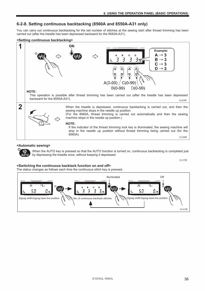
6-2-8. Setting continuous backtacking (8560A and 8550A-A31 only) You can carry out continuous backtacking for the set number of stitches at the sewing start after thread trimming has been carried out (after the treadle has been depressed backward for the 8550A-A31).
<Setting continuous backtacking>
1 NOTE:�
This operation is possible after thread trimming has been carried out (after the treadle has been depressed backward for the 8550A-A31).
2 When the treadle is depressed, continuous backtacking is carried out, and then the sewing machine stops in the needle up position. (For the 8560A, thread trimming is carried out automatically and then the sewing machine stops in the needle up position.)
NOTE:�If the indicator of the thread trimming lock key is illuminated, the sewing machine will stop in the needle up position without thread trimming being carried out (for the 8560A).
<Automatic sewing>�
When the AUTO key is pressed so that the AUTO function is turned on, continuous backtacking is completed just by depressing the treadle once, without keeping it depressed.
<Switching the continuous backtack function on and off> The status changes as follows each time the continuous stitch key is pressed.
No. of continuous backtack stitches
Off
Zigzag width/zigzag base line position Zigzag width/zigzag base line position
Illuminated
3440M
Example:
2159M
2147M
3441M

Z-8550A, 8560A
6. USING THE OPERATION PANEL (BASIC OPERATIONS)
37
6-2-9. Setting fixed stitches/name label sewing (8560A, 8550A-A31 only) You can carry out fixed stitch/name label sewing for the set number of stitches at the sewing start after thread trimming has been carried out (after the treadle has been depressed backward for the 8550A-A31).��
�
�
�
�
�
�
�
� <Setting fixed stitch sewing>
1
��� 1�250��� ��
2 After the set number of stitches in E (fixed stitches) have been sewn, the sewing machine stops in the needle position that has been set by the needle up/down key (refer to p.40). After this, normal sewing is carried out if the treadle is depressed.
3 After the thread is trimmed (after the treadle has been depressed backward for the 8550A-A31), fixed stitch sewing mode is enabled.
<Start and end backtack sewing> The start backtack key and end backtack key can be pressed to turn on the backtack sewing function.
<Automatic sewing> When the AUTO key is pressed to turn on the automatic sewing function, the fixed stitches are sewn simply by depressing the treadle once without needing to depress it continuously. After this the sewing machine stops in the needle up position. (For the 8560A, thread trimming is carried out automatically and then the sewing machine stops in the needle up position.)
<If using a solenoid-type presser lifter (Option)> When the AUTO function is set to ON, the number of stitches for E is sewn, and then the presser foot is also raised automatically.
Example:
3443M3442M
E = Number of fixed stitches (***) E = Number of fixed stitches (***)
Start point/end point
E
F = Number of second fixed stitches (***)
The sewing machine can be stopped automatically once the setnumber of stitches (***) have been sewn.
Name label sewing can be carried out for the set number of stitches (***). At the � points, sewing will stop at the needle positions that have been set using the needle up/down keys (refer to page 40).
F
3444M
2159M
2160M
3406M 3407M
2147M

Z-8550A, 8560A
6. USING THE OPERATION PANEL (BASIC OPERATIONS)
38
<Setting name label sewing>
1
2 After the set number of stitches in E (fixed stitches) have been sewn, the needle bar stops in the position that has been set by the needle up/down key (refer to p.40). After this, rotate the material.
3 After the set number of stitches in F (fixed stitches) have been sewn, the needle bar stops in the position that has been set by the needle up/down key (refer to p.40). After this, rotate the material.�
4
Repeat steps 2 and 3 above.
5 Thread trimming is carried out. (8560A)
<Start and end backtack sewing> The start backtack key and end backtack key can be pressed to turn on the backtack sewing function.
<Automatic sewing>
When the AUTO key is pressed to turn on the automatic sewing function, the fixed stitches in E and F are sewn respectively simply by depressing the treadle once without needing to depress it continuously. After the second number of F stitches is sewn, the sewing machine stops in the needle up position. (For the 8560A, after the second number of F stitches is sewn, the thread is trimmed automatically and then the sewing machine stops in the needle up position.)
<If using a solenoid-type presser lifter (Option)> After the fixed stitches in E and F are sewn, the presser foot is also lifted automatically. <Switching the fixed stitch/name label sewing function on and off>
From 1 to 250 stitches can be set for the E and F stitch numbers.
No. of fixed stitch/name label stitches
Off
Zigzag width/zigzag base line position Zigzag width/zigzag base line position
Illuminated
Example:
3445M
2159M
2159M
2159M
2160M
3406M 3407M
2147M
3446M

Z-8550A, 8560A
6. USING THE OPERATION PANEL (BASIC OPERATIONS)
39
6-3. Using the lower thread counter • The lower thread counter can be used to let you know approximately how much lower thread is remaining. • The value displayed by the lower thread counter display is reduced by 1 from the initial setting value each time the sewing
machine sews 10 stitches, and a warning is given when the counter reaches “-1”.
<Initial value setting>
1 ���
�
�
�
�
�
�
�
�(Press for 2 seconds or more)
After about 2 seconds, the buzzer will sound and the lower thread counter display will show the initial value which was set previously.��
�
�
�
�
�
�
�
2
• When the key is pressed, the setting increases. • When the key is pressed, the setting decreases. • If you hold down the keys, the setting will change more quickly. • If a value of “0” is set, the lower thread counter will not operate. • The initial setting value will be accepted when sewing starts.�
�
<Lower thread counter operation> �
�
�
�
�
�
�
�
�
�
�
�
�
�
�
�
�1. When sewing is carried out, the value shown in the lower thread counter display is reduced by 1 for every 10 stitches
sewn. (When the value becomes less than zero “0”, a minus sign appears and counting continues to a maximum of “-999”.)
2. When the value is less than “0”, a warning icon (1) illuminates and an electronic buzzer sounds for 10 seconds. 3. Sewing can continue until the treadle is depressed backward, even if the value becomes less than “0”. (After the treadle is
depressed backward, the sewing machine will not operate even when the treadle is depressed forward again.) • When the RESET key (2) is pressed, the warning icon (1) will switch off and the display will return to the initial value.
Sewing can then be carried out using the treadle. • Use the keys to change the initial value.
* If you would like to return the lower thread counter display to the initial value before it becomes less than “0”, press the RESET key (2) for 2 seconds or more.
2166M
2167M 2168M 2169M
3447M
Press theRESET key (2).
(Initial value) Reduces by 1 forevery 10 stitchessewn
3423M

Z-8550A, 8560A
7. USING THE OPERATION PANEL (ADVANCED OPERATIONS)
40
7. USING THE OPERATION PANEL (ADVANCED OPERATIONS)
The operations described in this section should only be carried out by a technician.
7-1. Names and functions
(29) Slow start key
• When this key is pressed so that the slow start icon (33) illuminates, the first three stitches sewn after the thread is trimmed are sewn at slow speed (220 rpm). After this, the sewing speed corresponds to the treadle depression amount.�
• If you press this key again while the icon (33) is illuminated, the icon (33) will turn off.
(30) Correction key�
• When this key is pressed so that the correction icon (34) illuminates, correction sewing can be carried out.�When the treadle is at the neutral position and the actuator is pressed once gently, one stitch is sewn and then sewing stops; when the actuator is pressed continuously, sewing is carried out at 220 rpm. NOTE:
• If you press the actuator while sewing is in progress, backtack stitches will be sewn.�
• If sewing pattern [ 5- *A] or [ 6- *A] is selected, the actuator can be used to switch to reflection patterns, so that correction sewing cannot be carried out. (Correction sewing is possible if the setting is [ 5- *_ ] or [ 6- *_ ].)
• If you press this key again while the icon (34) is illuminated, the icon (34) will turn off.
(31) Needle up/down key
Use this key to select whether the needle bar stops in the up position or the down position when the treadle is returned to the neutral position and sewing stops.�• When the needle up icon (35) is illuminated, the needle bar stops in the up position.• When the needle down icon (36) is illuminated, the needle bar stops in the down
position.
(32) P1key, P2key This key is used when retrieving user programs.�
• This key is disabled if no user programs are available.��
3449M
3450M
2207M 2208M 3451M
These are used for making advanced operating settings. They should only be used by a technician.
* The illustration shows the Z-ST (for 8550A-031).
3448M
3452M 3453M

Z-8550A, 8560A
7. USING THE OPERATION PANEL (ADVANCED OPERATIONS)
41
7-2. Adjusting the needle up stop position 1. While pressing the needle up/down key (1), turn on the
power switch. 2. “n.0 xx” will appear in the main display (2).
(“xx” is the setting value for the needle up stop position, and “0” is the default setting.)
3. Press the or key (3) to change the setting value for the needle up stop position.
• If you press the key, the setting value will increase up to 10 and the needle up stop position will become lower. • If you press the key, the setting value will decrease down to -10 and the needle up stop position will become higher.
4. Press the ENTER key (4) for two seconds or more. A long buzzer will sound and the main display (2) will change to stitch number display mode. (This completes the needle up stop position setting.)
* A setting value of “10” corresponds to an angle of rotation
of approximately 10° for the upper shaft. NOTE:�
If the needle bar is not at the needle up stop position, “UP” will be displayed.
2138M 2139M
3454M
3455M
Becomes higher
Becomes lower
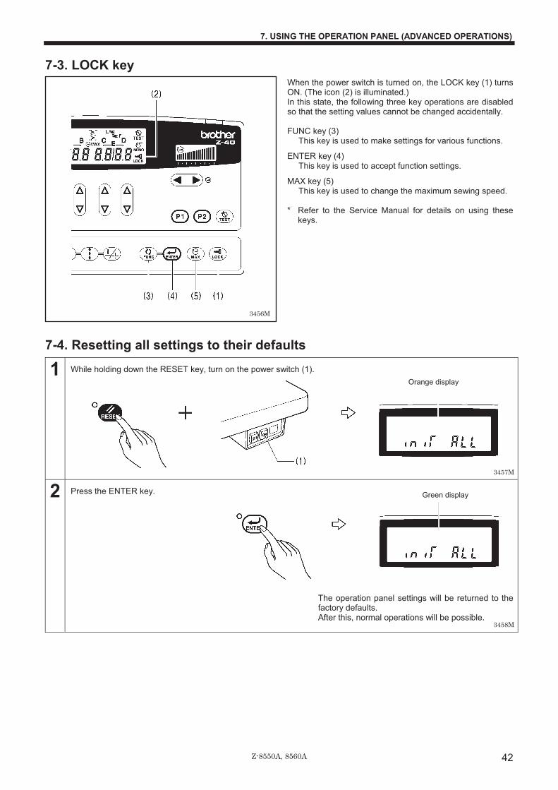
Z-8550A, 8560A
7. USING THE OPERATION PANEL (ADVANCED OPERATIONS)
42
7-3. LOCK key When the power switch is turned on, the LOCK key (1) turns ON. (The icon (2) is illuminated.) In this state, the following three key operations are disabled so that the setting values cannot be changed accidentally.
FUNC key (3)
This key is used to make settings for various functions.
ENTER key (4) This key is used to accept function settings.
MAX key (5) This key is used to change the maximum sewing speed.
* Refer to the Service Manual for details on using these keys.
7-4. Resetting all settings to their defaults
1 While holding down the RESET key, turn on the power switch (1).
2 Press the ENTER key.
The operation panel settings will be returned to the factory defaults. After this, normal operations will be possible.
Orange display
Green display
3456M
3457M
3458M

Z-8550A, 8560A
7. USING THE OPERATION PANEL (ADVANCED OPERATIONS)
43
7-5. Using user programs Sewing pattern, zigzag width, zigzag base line position and zigzag stop position settings can be combined and recorded in up to three different types of pattern (P1, P2 and P12). It can be useful for combinations of frequently-used settings such as sewing pattern and zigzag width (sewing data) are recorded into user programs, so that they can be easily retrieved and used. * For the 8560A and 8550A-A31, backtacking and fixed stitch/name label stitch settings can also be recorded into user
programs.
7-5-1. Recording sewing data
1 • Select the sewing pattern. (Refer to page 26.) • Set the zigzag width and zigzag base line position. (Refer to pages 31�32.) • If necessary, set the zigzag stop position. (Refer to page 33.)
Note: If any settings such as the zigzag stop position are not set, the current setting values will be recorded, so check all settings that can be recorded.
2 While pressing the TEST key, press the P1 key. [SEL. Pn] will appear in the main display and user program recording mode will be enabled.
NOTE:
If the TEST key is pressed at this time, the selection can be cleared.
�
�
�
�
3 Press the key(s) (P1, P2 or P1 + P2) to use for recording the sewing data. (For P1 + P2, press and hold P1 and then press P2.) The program number (P1, P2 or P12) will flash in the main display. (You can press the keys again to change the selection while the display is flashing.)
When selecting P1 to use for retrieving the program:
When selecting P2 to use for retrieving the program:
When pressing P1 and P2 together to retrieve the program:
4 When the ENTER key is pressed, the sewing data is recorded in the specified user program.
• The main display will stop flashing and illuminate steadily, and the recording will be complete.
• You can then sew the recorded data straight away.
To use sewing data that has been recorded in a user program for sewing after some other sewing data has been sewn, retrieve the sewing data while referring to the following page.
3460M
3452M 3453M 3461M 3462M�3464M
3465M

Z-8550A, 8560A
7. USING THE OPERATION PANEL (ADVANCED OPERATIONS)
44
7-5-2. Retrieving recorded sewing data Sewing data that has been recorded in a user program can be retrieved simply by pressing a key.
NOTE: A user program cannot be retrieved if it contains no sewing data. Record sewing data into a user program before carrying out this operation. (Refer to the previous page.)
1 Press the key (P1, P2 or P1 + P2) that was used to record the sewing data to be retrieved. (For P1 + P2, press and hold P1 and then press P2.) The program number (P1, P2 or P12) will appear in the main display.
When using P1 to retrieve the program:
When using P2 to retrieve the program:
When using P1 + P2 to retrieve the program:
2 The sewing data recorded in the user program will be sewn. The program number (P1, P2 or P12) will appear in the main display while sewing is in progress.
3452M 3453M 3461M 3462M—3464M
2159M

Z-8550A, 8560A
7. USING THE OPERATION PANEL (ADVANCED OPERATIONS)
45
7-6. Setting the maximum sewing speed
1 If the LOCK key icon (1) is illuminated, press the LOCK key for 2 seconds or more to cancel the lock.
• The icon (1) will switch off and the lock will be cancelled.
2 • The main display will change from an orange display to a green display.
3 • The maximum sewing speed can be set to a speed from 220 rpm to the maximum sewing speed that has been set for the head detector unit.
• If all numbers in the sewing speed control display (2) are illuminated, sewing will be carried out at the maximum speed that is set here when the treadle is fully depressed.
4 • The icon (1) will illuminate and the setting will be locked.
5 • When sewing starts, the sewing speed display disappears and returns to the orange display�zigzag width/zigzag base line position display)
�
3459M
2235M
2159M
3468M
Example:
3467M
Maximum sewing speed
Start backtack sewing speed
For the 8550A-A31 and 8560A, this shows thestart backtacking speed.
(Current setting)
(Press for 2 seconds or more)
(Press for 2 seconds or more)� 3469M

Z-8550A, 8560A
8. SEWING
46
8. SEWING CAUTION
Attach all safety devices before using the sewing machine. If the machine is used without these devices attached, injury may result. Turn off the power switch at the following times. The machine may operate if the treadle is depressed by mistake, which could result in injury. • When threading the needle • When replacing the bobbin and needle • When not using the machine and when leaving the machine unattended Do not touch any of the moving parts or press any objects against the machine while sewing, as this may result in personal injury or damage to the machine. Never touch the knife on the face plate when opening the thread takeup guard cover at times such as when taking up slack in the thread, otherwise injury may result. Use both hands to hold the machine head when tilting it back or returning it to its original position. If only one hand is used, the weight of the machine head may cause your hand to slip, and your hand may get caught.
1. Press the ON power switch. (Refer to page 13.)
2. Use the operation panel to make the necessary settings such as sewing pattern and zigzag width. (Refer to page 21.)
3. Set the stitch length using the stitch length dial. (Refer to page 18.)
4. Depress the treadle to start sewing.
3470M
Example: Pattern number [ 6-1 ]
Zigzag width (00.0) mm
Stitch length 0.0 mm
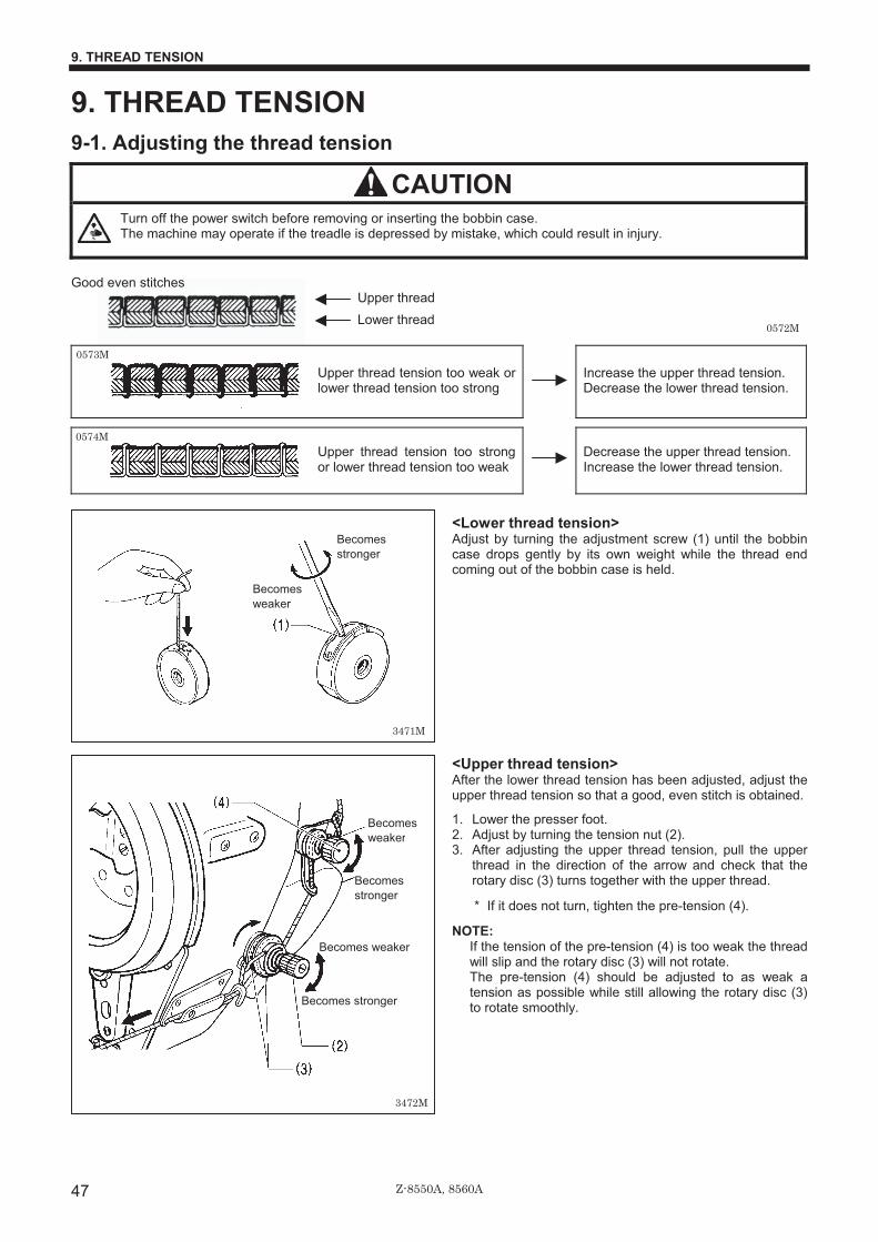
Z-8550A, 8560A
9. THREAD TENSION
47
9. THREAD TENSION 9-1. Adjusting the thread tension
CAUTION Turn off the power switch before removing or inserting the bobbin case.
The machine may operate if the treadle is depressed by mistake, which could result in injury.
Good even stitches
Upper thread Lower thread
Upper thread tension too weak or lower thread tension too strong
Increase the upper thread tension. Decrease the lower thread tension.
Upper thread tension too strong or lower thread tension too weak
Decrease the upper thread tension. Increase the lower thread tension.
<Lower thread tension> Adjust by turning the adjustment screw (1) until the bobbin case drops gently by its own weight while the thread end coming out of the bobbin case is held.
<Upper thread tension> After the lower thread tension has been adjusted, adjust the upper thread tension so that a good, even stitch is obtained.
1. Lower the presser foot.�2. Adjust by turning the tension nut (2). 3. After adjusting the upper thread tension, pull the upper
thread in the direction of the arrow and check that the rotary disc (3) turns together with the upper thread.
* If it does not turn, tighten the pre-tension (4).
NOTE: If the tension of the pre-tension (4) is too weak the thread will slip and the rotary disc (3) will not rotate. The pre-tension (4) should be adjusted to as weak a tension as possible while still allowing the rotary disc (3) to rotate smoothly.�
�
0573M
0574M
0572M
3471M
Becomes stronger
Becomes weaker
3472M
Becomes weaker
Becomes stronger
Becomes weaker
Becomes stronger

Z-8550A, 8560A
9. THREAD TENSION
48
9-2. Adjusting the presser foot pressure Correct stitches
Increase the pressure.
Skipped stitches occur
Uneven stitch length
Stitches are puckered
Decrease the pressure.
The presser foot pressure should be as weak as possible, but strong enough so that the material does not slip.
1. Loosen the adjusting nut (1).�2. Turn the presser adjusting screw (2) to adjust the
presser foot pressure. 3. Tighten the adjusting nut (1). �
�
�
�
�
�
�
�
�
0578M
0580M
0579M
3473M
Becomes stronger Becomes weaker
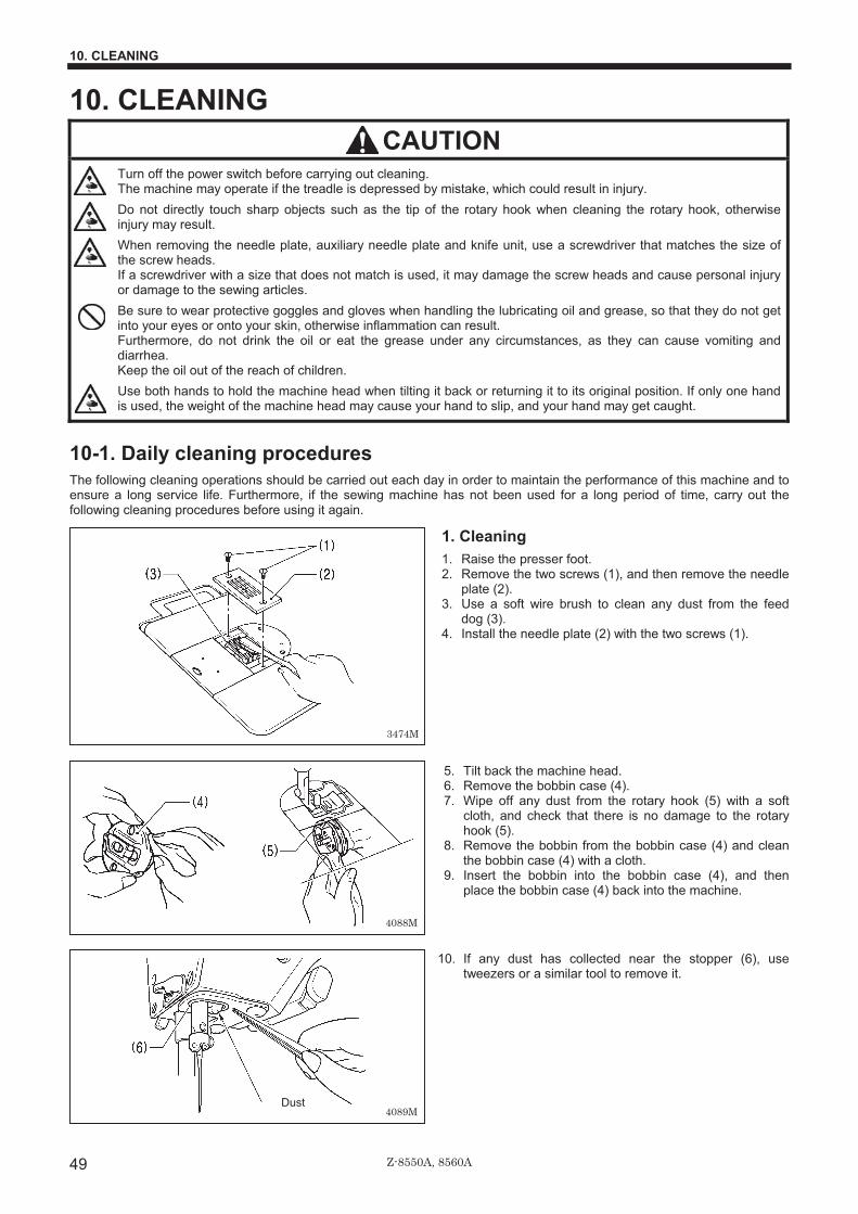
Z-8550A, 8560A
10. CLEANING
49
10. CLEANING CAUTION
Turn off the power switch before carrying out cleaning. The machine may operate if the treadle is depressed by mistake, which could result in injury. Do not directly touch sharp objects such as the tip of the rotary hook when cleaning the rotary hook, otherwise injury may result. When removing the needle plate, auxiliary needle plate and knife unit, use a screwdriver that matches the size of the screw heads. If a screwdriver with a size that does not match is used, it may damage the screw heads and cause personal injury or damage to the sewing articles. Be sure to wear protective goggles and gloves when handling the lubricating oil and grease, so that they do not get into your eyes or onto your skin, otherwise inflammation can result. Furthermore, do not drink the oil or eat the grease under any circumstances, as they can cause vomiting and diarrhea. Keep the oil out of the reach of children. Use both hands to hold the machine head when tilting it back or returning it to its original position. If only one hand is used, the weight of the machine head may cause your hand to slip, and your hand may get caught.
10-1. Daily cleaning procedures The following cleaning operations should be carried out each day in order to maintain the performance of this machine and to ensure a long service life. Furthermore, if the sewing machine has not been used for a long period of time, carry out the following cleaning procedures before using it again.
1. Cleaning�1. Raise the presser foot.�2. Remove the two screws (1), and then remove the needle
plate (2).�3. Use a soft wire brush to clean any dust from the feed
dog (3). 4. Install the needle plate (2) with the two screws (1).��
�
�
�
�
�
5. Tilt back the machine head. 6. Remove the bobbin case (4). 7. Wipe off any dust from the rotary hook (5) with a soft
cloth, and check that there is no damage to the rotary hook (5).
8. Remove the bobbin from the bobbin case (4) and clean the bobbin case (4) with a cloth.
9. Insert the bobbin into the bobbin case (4), and then place the bobbin case (4) back into the machine.
10. If any dust has collected near the stopper (6), use tweezers or a similar tool to remove it.
�
�
�
�
�
3474M
4088M
4089MDust

Z-8550A, 8560A
10. CLEANING
50
2.�Lubrication�A. Gearbox oil quantity NOTE:�
• Check the quantity of oil in the gearbox immediately after tilting back the machine head. When the machine head is left for long periods in the tilted-back position, the amount of oil in the felt inside the gearbox drops and the oil level seen from the oil window (1) rises, so that it becomes impossible to measure the actual oil level accurately.
• The position of the oil level in the oil window (1) will vary depending on the angle of the machine head. Tilt back the machine head while the head rest (2) is installed in the correct position as shown in the table processing diagram on page 4 (refer to page 7).
<Checking the oil quantity> The oil level should normally be approximately 1 mm above the center reference line in the oil window (1). (120 ml of lubricating oil is added to the gearbox at the time of shipment from the factory.)
1. Look at the oil window (1) from directly in front. 2. If the oil level is below the normal level, add more
lubricating oil as described in the following procedure.
<Lubrication> Use only the lubricating oil (Nisseki Mitsubishi Sewing Lube 10N; VG10) specified by Brother.�* If this type of lubricating oil is difficult to obtain, the
recommended oil to use is <Exxon Mobil Essotex SM10; VG10>.�
1. Remove the rubber cap (3). 2. Add lubricating oil until the oil level is approximately 1
mm above the center reference line in the oil window (1). Do not pour all of the lubricating oil in at once at this time. Pour the lubricating oil 10 ml at a time while checking the oil window (1). NOTE:�
Do not pour too much lubricating oil into the specified location. If too much oil is added, oil leaks may result.
3. Insert the rubber cap (3) securely. 4. Return the machine head to its original position.
NOTE:�
The rubber cap (3) has a hole in it for adjusting the air pressure. When replacing the rubber cap (3) use only the replacement part specified by Brother.
3477M
2188M
Approx. 1 mm
3476M
Approx. 1 mm
3478M

Z-8550A, 8560A
10. CLEANING
51
B.�Oil tank oil quantity�Check the oil gauge window (1), and add more oil if the oil gauge (2) is below the lower reference line. (Refer to page 9.)
3. Checking 1. Replace the needle if it is bent or if the tip is broken.�2. Check that the upper threads have been threaded
correctly. (Refer to page 17.) 3. Carry out a test sewing. �
�
�
�
�
�
�
�
�
�
�
�
�
�
�
�
�
3479M
Upper reference line
Lower reference line
3798M

Z-8550A, 8560A
10. CLEANING
52
10-2. Applying grease (When “GrEASEUP” appears…) If “GrEASEUP” flashes on the main display (1) and a buzzer sounds when the power switch is turned on, it means that grease needs to be applied. (The sewing machine will not operate at this time, even if the treadle is depressed.) Apply grease while referring to the following page.
< To continue sewing temporarily without applying grease > 1. Press the RESET key (2). 2. The main display (1) will switch to zigzag width/zigzag base line position display mode, and sewing can then start when
the treadle is depressed. (The power indicator (3) will flash.)
NOTE: • The “GrEASEUP” notification will continue to appear and the power indicator (3) will flash each time the power switch
is turned on until you apply grease and reset the cumulative operating time (refer to pages 53-54). • If you continue to use the sewing machine after the “GrEASEUP” notification appears without applying grease (or
without carrying out the reset procedure), “Err100” will appear after a certain period of time and the sewing machine will be forcibly prevented from operating for safety reasons. If this happens, apply grease and carry out the reset procedure.
* If you continue to use the sewing machine after carrying out the reset procedure but without applying grease, problems with the sewing machine may result.
3481M

Z-8550A, 8560A
10. CLEANING
53
<Applying grease> Use Brother-specified “Grease unit (SA8837-001)”.
1. Using the tube
2. Applying grease 1. Turn the power switch to “OFF”. 2. Apply grease in the places indicated by arrows [A]�[G] below.
1. Remove the screws 2. Apply grease to each of the
holes until the grease overflows slightly.
3. Tighten the screw to push inthe grease.
4. Turn the machine pulley byhand to move the needle barup and down several times inorder to disperse the grease�
5. Use a rag to wipe away any excess grease on and around the screws. NOTE:�
For screws (1) and (2), remove the screws oncemore and then wipe around the seats with therag. After doing this, securely tighten the screws(1) and (2).
3482M
3483M
3485M
3486M
3484M
Grease
3487M
Grease
4087M

Z-8550A, 8560A
10. CLEANING
54
After applying grease in the places indicated by arrows [A]�[G] above, carry out the reset operation described below.
<Resetting the cumulative operating time>
After the grease has been applied, carry out the following procedure to reset the cumulative time between grease applications. 1. Turn the power switch to “ON”. “GrEASEUP” will flash in
the main display (1) and the buzzer will sound. 2. Press the RESET key (2). The main display (1) will
switch to zigzag width/zigzag base line position display mode.
3. Press and hold the LOCK key (4) for 2 seconds or more. The lock icon (5) will switch off and the lock will be released.
4. Press the FUNC (Function) key (6). “n.134 xxx” will appear in green in the main display (1). (xxx represents the time between grease applications.)
5. Press the rightmost key (7). The “xxx” will change to “0”.
6. Press and hold the ENTER key (8) for two seconds or more. A long beep will sound, and then the main display (1) will switch to zigzag width/zigzag base line position display mode.
7. Depress the treadle to run the sewing machine for 1 second or more.
8. Turn the power switch to “OFF”. (This completes the reset procedure.)
3488M
3489M 2139M
Use the tip of a long brush or similar to applyapprox 1 g of grease to the places indicatedby arrows [E] to [G].
After applying approximately 1 g of grease tothe groove, move the needle bar (3) back andforth with your finger to spread the grease.
2. Apply approx 1 g of grease.
1. Pull the needle bar (3) forward with your finger.
3. Turn the machine pulley to gently apply the grease onto the felt.
4. Move the needle bar (3) back and forth with your finger to spread the grease.
Felt

Z-8550A, 8560A
11. REPLACING PARTS
55
11. REPLACING PARTS CAUTION
Replacement of parts should only be carried out by a qualified technician. Turn off the power switch and disconnect the power cord from the wall outlet before replacing any parts, otherwise the machine may operate if the treadle is pressed by mistake, which could result in injury. When removing the needle plate, auxiliary needle plate and knife unit, use a screwdriver that matches the size of the screw heads. If a screwdriver with a size that does not match is used, it may damage the screw heads and cause personal injury or damage to the sewing articles. Use only the proper replacement parts as specified by Brother.
11-1. Fixed knife and movable knife (8560A only) <Removal>
1. Remove the two screws (1), and then remove the knife unit (2).
2. Remove the four screws (3), and then remove the knife holder (4).
3. Remove the fixed knife (5) and the movable knife (6).
<Installation>
1. Install the fixed knife (5) and the movable knife (6) to the knife base plate (7).
2. Install the knife holder (4) with the four screws (3). 3. Install the needle plate (8) if it is not already installed. 4. Install the knife unit (2) securely to the edge of the
needle plate (8) with the two screws (1).
3491M
3799M

Z-8550A, 8560A
11. REPLACING PARTS
56
11-2. Gauge parts (presser foot, needle plate and feed dog)
11-2-1. Replacing the stopper If using the presser foot, needle plate and feed dog for a zigzag width of something other than 8 mm, needle breakages may occur when the sewing machine is operating, so be sure to limit the zigzag width and replace the stopper as described below.
For 8 mm (A=16.4mm) White Standard part (Installed to the sewing machine
at the time of purchase)
For 5 mm (A=13.4mm) Black Accessory part
For 3 mm (A=11.4mm) Blue Optional part
Stopper
For 10 mm (A=18mm) White Optional part
* Depending on specifications, some sewing machines may have a stopper for sizes other than 8 mm installed as a standard part. In such a case, check the size by means of dimension A and the color.
<Replacing the stopper> � If using the optional presser foot and needle plate for a zigzag width of 5 mm, replace the stopper with one for 5 mm
(black). � If using the special-order presser foot and needle plate for a zigzag width of 3 mm, replace the stopper with one for 3 mm
(blue). � If using the optional presser foot and needle plate for a zigzag width of 10 mm, replace the stopper with one for 10 mm
(white, A=18 mm)
1. Remove the two screws (1), and then remove the stopper plate (2).
2. Remove the stopper (3) which is inserted into the stopper plate (2), and then install the stopper (3) which matches the presser foot and needle plate.
3. Install the stopper plate (2) to the machine head, and then securely tighten the two screws (1).
4. Turn on the power. 5. Set the zigzag width to the maximum width for the gauge
parts. 6. Turn the machine pulley by hand and check that the
needle does not touch any of the needle holes in the gauge parts, and that the needle bar does not touch the stopper (3).
Limiting the zigzag width (added function using memory switches)
If using a presser foot and needle plate for a zigzag width of something other than 8 mm, problems such as the needle bar touching the stopper may occur if the zigzag width is set by mistake to be larger than the needle hole width of the presser foot and needle plate. In order to prevent operation panel setting errors such as this, change the memory switch settings to match the needle hole width of the presser foot and needle plate.
Press for 2 seconds or more. (The lock will be canceled.)
Select memory switch No. 101.
Set the zigzag width value to between 3.0�10.0mm.
The buzzer will sound for about 1 second (Complete)
Press for 2 seconds or more. (Lock will be applied.)
Notes when replacing gauge parts (Points which must be noted)
3493M 3494M 3495M
Memory switch
3496M
Example: zigzag width
3493M3497M
A 1388M
3817M

Z-8550A, 8560A
11. REPLACING PARTS
57
11-2-2. Changing the feed amount to long stitch specifications (from 2.0mm to 5.0mm) 1. Replace the feed dog (1) and needle plate (2) with the
ones for long stitches. 2. After this, change the maximum feed amount as
described below.
11-2-3. Changing the maximum feed amount If the feed dog has been replaced by one that does not match the feed amount that is currently being used, the feed dog may touch the needle plate if the stitch length dial or condense dial are mistakenly set to settings that are larger than the maximum feed amount for the feed dog, and this could cause problems such as damage or noise. In order to prevent dial setting errors such as this, change the maximum feed amount setting for the sewing machine to match the maximum feed amount for the feed dog.
1. Tilt back the machine head. 2. For models/specifications other than the 8550A-031,
loosen the two screws (1) so that the quick reverse solenoid (2) can be moved up and down.
3. Loosen the screws (3) and (4). 4. Move the stopper (5) down as far as possible, and move
the stopper (6) up as far as possible
5. Turn the stitch length dial (7) and the condense dial (8) to the maximum feed amount for the feed dog being used. (Set the condense dial (8) to a negative number.)
3498M
3499M
3500M
3501M

Z-8550A, 8560A
11. REPLACING PARTS
58
6. Check that the feed dog does not touch the needle plate both when the reverse lever (9) is not lowered and when it is lowered. If it touches, adjust the forward/back installation position (centering) of the feed dog.
7. Without lowering the reverse lever (9), move the stopper (5) up until it touches F-regulator connecting rod (10), and then tighten the screw (3). (Fig. A)
8. With the reverse lever (9) lowered all the way, move the stopper (6) down until it touches the F-regulator connecting rod (10), and then tighten the screw (4). (Fig. B)
9. For models/specifications other than the 8550A-031, with the reverse lever (9) lowered all the way (with the plunger (11) of the quick reverse solenoid moved to its highest position), touch the quick reverse solenoid (2) against section (A) of the plunger (11), and then tighten the two screws (1).
3502M
3503M
[A]
[B]
3504M
3505M

Z-8550A, 8560A
12. STANDARD ADJUSTMENTS
59
12. STANDARD ADJUSTMENTS �CAUTION
Maintenance and inspection of the sewing machine should only be carried out by a qualified technician. Ask your Brother dealer or a qualified electrician to carry out any maintenance and inspection of the electrical system.�Turn off the power switch and disconnect the power cord from the wall outlet at the following times, otherwise the machine may operate if the treadle is depressed by mistake, which could result in injury.�
• When carrying out inspection, adjustment and maintenance
• When replacing consumable parts such as the rotary hook�
If the power switch needs to be left on when carrying out some adjustment, be extremely careful to observe all safety precautions.
Use both hands to hold the machine head when tilting it back or returning it to its original position. If only one hand is used, the weight of the machine head may cause your hand to slip, and your hand may get caught. Never touch the knife on the face plate when opening the thread takeup guard cover, otherwise injury may result. If any safety devices have been removed, be absolutely sure to re-install them to their original positions and check that they operate correctly before using the machine. When removing the needle plate, auxiliary needle plate and knife unit, use a screwdriver that matches the size of the screw heads. If a screwdriver with a size that does not match is used, it may damage the screw heads and cause personal injury or damage to the sewing articles.
12-1. Actuator position The installation position of the actuator (1) can be adjusted as shown in the illustration. Adjust so that it is in a position where it is easy to operate. NOTE:�
If using a thread wiper device, adjust the position of the actuator (1) within the range of (A) so that it does not touch the thread wiper.
1. Loosen the two screws (2). 2. Move the switch installation plate (3) to move the
actuator (1) to the desired position. 3. Tighten the two screws (2).
3507M
<Rear side>
3800M

Z-8550A, 8560A
12. STANDARD ADJUSTMENTS
60
12-2. Adjusting the safety switch position The safety switch (1) is normally installed as shown in figure [A]. However, if the processing method used for the table leaves too much space between the machine head and the table hole, it may adversely affect the operation of the safety switch (1).
<Adjustment method> The standard amount of clearance between the machine head and the table hole is 1.5 mm. If the clearance is 3.5 mm or more, install the safety switch (1) so that the washer (2) is on the machine head side as shown in Figure [B].
* If the position cannot be satisfactorily adjusted in this way, add more washers of the same thickness.
<Safety switch operation>
3691M
3692M
By changing the position of the safety switch,the required spring stroke can be maintained.
Clearance is too large.
If the spring stroke is too small, the safetyswitch will not operate.
Reduce the clearance.
3.5 mm or more
3690M
Sewing machine
Table
3801M

Z-8550A, 8560A
12. STANDARD ADJUSTMENTS
61
12-3. Adjusting the thread tension spring <Thread tension spring position> The standard position of the thread tension spring (1) is 5-8 mm above the surface of the thread guide (3) when the presser foot (2) is lowered. 1. Lower the presser foot (2). 2. Loosen the set screw (4). 3. Turn the thread tension bracket (5) to adjust the spring
position. 4. Securely tighten the set screw (4).
<Thread tension spring tension> The standard tension of the thread tension spring (1) is 0.25 to 0.30 N. 1. Press the upper thread slightly above the thread tension
bracket (5) with a finger to stop the thread spooling out. 2. Pull the upper thread down until the thread tension spring
(1) starts to move down, and measure he tension of the thread tension spring (1) at this point.
3. Insert the tip of a screwdriver into the groove in the thread tension stud (6) and turn it to adjust the tension of the thread tension spring (1).
NOTE:�
If using a tension gauge (7) (sold separately) to measure the tension, take the reading from the scale on the side of the red line.
3512M
3513M
Becomes weaker
Scale
Becomes stronger
3802M

Z-8550A, 8560A
12. STANDARD ADJUSTMENTS
62
12-4. Adjusting the presser foot height The standard height of the presser foot (1) is 6 mm when the presser foot (1) is raised by means of the presser bar lifter (2). 1. Loosen the two screws (3) and then remove the thread
take-up guard (4). 2. Loosen the nut (5) of the adjustment screw (6), and then
turn the adjustment screw (6) so that there is no pressure applied to the presser foot.
3. Raise the presser bar lifter lever (2). The presser foot (1) will also rise.
4. Loosen the screw (7) and move the presser bar (8) up and down to adjust the height of the presser foot (1) to 6 mm.
5. Tighten the screw (7). 6. Adjust the presser foot pressure using the adjustment
screw (6), and then tighten the nut (5). 7. Install the thread take-up guard (4) with the two screws
(3).
12-5. Adjusting the feed dog height The standard height of the feed dog (1) when it is raised as far as possible above the surface of the needle plate is as given below. <8550A> 1 mm <8560A> At the front 1.1 mm At the back 0.9 mm
1. Turn the machine pulley to move the feed dog (1) to its
highest position above the needle plate. 2. Tilt back the machine head. 3. Loosen the screw (2). 4. Turn the pin (3) to move the feed bar (4) up and down in
order to adjust the height. 5. Securely tighten the screw (2).
3516M
Highest position Lowest position
3804M
<8550A>
<8560A>
3803M

Z-8550A, 8560A
12. STANDARD ADJUSTMENTS
63
12-6. Adjusting the feed dog angle The standard angle for the feed dog (1) is for the top of the needle plate to be parallel with the top of the feed dog (1) (for the 8550A) or raised slightly at the side closest to the operator (for the 8560A) when the feed dog (1) is raised to its highest position above the needle plate. (with the O mark on the feed bracket shaft (2) aligned with the mark on the feed rocker bracket arm (3)). 1. Turn the machine pulley to move the feed dog (1) its
highest position above the needle plate. 2. Tilt back the machine head. 3. Loosen the set screw (4). 4. Turn the feed bracket shaft (2) in the direction of the
arrow within a range of 90º with respect to the standard position. • In order to prevent puckering, lower the front of the
feed dog (1). (Figure A) • In order to prevent the material from slipping, raise
the front of the feed dog (1). (Figure B) 5. Securely tighten the set screws (4).
* When the angle of the feed dog (1) is adjusted, the height
and forward/back position of the feed dog (1) will also change and will need to be readjusted.
12-7. Adjusting the forward/back position of the feed dog The clearance between the feed dog (1) and the needle plate should be the same at the front and back of the feed dog (1) when the feed dog (1) is moved to its furthest forward and furthest back positions by turning the machine pulley. 1. Tilt back the machine head. 2. Loosen the two screws (2). 3. Turn the feed rocker bracket arm (3) to adjust the
forward/back position of the feed dog (1). 4. Securely tighten the two screws (2).
3518M
3517M
standard
Lower the front
Raise the front
(front)
3520M
3519M

Z-8550A, 8560A
12. STANDARD ADJUSTMENTS
64
12-8. Adjusting the needle bar height With the accessory needle bar height gauge (2) installed to the needle bar (1), adjust so that the needle bar height gauge (2) is touching the top of the needle plate (3) when the needle bar is at its lowest position. 1. Remove the needle (4) and the presser foot (5).
For the 8560A (Refer to Fig. A) 1) Remove the needle plate (3) and then auxiliary
needle plate (6). 2) Remove the spacer (7). 3) Place the needle plate (3) onto the needle plate
installation surface. 2. Install the accessory needle bar height gauge (2) to the
needle bar (1), and then tighten it with the set screw (8). 3. Loosen the screw (9). 4. Move the needle bar up or down to adjust so that the
needle bar height gauge (2) is touching the top of the needle plate (3) when the machine pulley is turned so that the needle bar (1) is at its lowest position.
5. Securely tighten the screw (9). 6. Remove the needle bar height gauge (2). 7. For the 8560A, install the spacer (7), needle plate (3)
and auxiliary needle plate (6). 8. Install the presser foot (5) and needle (4).
12-9. Needle and rotary hook timing 1. Turn on the power switch. 2. Press the TEST key (1) and check that the TEST icon (2)
is illuminated. (For safety purposes, be sure to carry out this step, as it prevents the motor from operating even if the treadle is depressed.)
3. Set both the zigzag width and the zigzag base line position to “0”. (Refer to pages 31-32.)
(Continued on next page)
3805M
For the 8560A (Fig. A)
3522M
3523M
Touching

Z-8550A, 8560A
12. STANDARD ADJUSTMENTS
65
4. Remove the presser foot (3), needle plate (4), auxiliary needle plate (5), feed dog (6) and spacer (7) (856A only).
5. Turn the machine pulley to raise the needle bar (8) from its lowest position until the reference line on the thread takeup (9) is aligned with the Ø mark on the face plate, and then check the following.
• The tip of the rotary hook (10) should be aligned with the center of the needle.
• The distance from the tip of the rotary hook (10) to the needle should be 0 to 0.05 mm.
6. If the above are not correct, loosen the two screws (11) and adjust the position of the rotary hook (12). After adjustment, securely tighten the two screws (11).
7. Set the zigzag width to the maximum setting (8 mm). 8. Turn the machine pulley to move the needle to its furthest
left position so that the tip of the rotary hook (10) is aligned with the center of the needle, and check that the distance from the upper edge of the needle hole to the tip of the rotary hook (10) is 0.2 to 0.5 mm at this time. * If the distance is not correct, adjust the height of the
needle bar. (Refer to page 64.) 9. If needle deflection occurs when sewing material with
joints, bend the needle guard (13) as shown in the illustration (A) so that it touches the needle. * After this, check that the clearance between the tip of
the rotary hook (10) and the needle is 0 to 0.05 mm. 10. Press the TEST key (1) so that the TEST icon (2)
switches off. (Normal sewing will then be possible.) Turn off the power to continue adjustment.
12-10. Bobbin case holder position bracket position Adjust so that the end of the bobbin case holder position bracket (1) is 0 to 0.5 mm back from end (A) of the inner rotary hook (2). * The end of the bobbin case holder position bracket (1)
must never extend to the right of end (A) of the inner rotary hook (2).
1. Loosen the screw (3) and adjust the position of the bobbin case holder position bracket (1).
2. Securely tighten the screw (3).
Maximum zigzag width
3526M 3527M
3525M
3528M
3806M

Z-8550A, 8560A
12. STANDARD ADJUSTMENTS
66
12-11. Adjusting the rotary hook lubrication amount
CAUTION Be careful not to touch your fingers or the lubrication amount check sheet against moving parts such as the rotary
hook or the feed mechanism when checking the amount of oil supplied to the rotary hook, otherwise injury may result.
Use the following procedure to check the amount of oil being supplied to the rotary hook after replacing the rotary hook or when changing the sewing speed. �
<Checking the lubrication amount> 1. Remove the thread from all points from the thread
take-up to the needle. 2. Use the lifting lever to lift the presser foot. 3. Run the machine at the normal sewing speed for
approximately 1 minute without sewing any material (following the same start/stop pattern as when actually sewing).
4. Place the lubrication amount check sheet (1) to the left of the rotary hook (2) and hold it there. Then run the sewing machine at the normal sewing speed for 10 seconds. (Any type of paper can be used as the lubrication amount check sheet (1).)
5. Check the amount of oil which has spattered onto the sheet.
�* Be sure to repeat this operation three to four times to
check average lubrication amounts. * If adjustment is necessary, carry out the following
operations in “Adjusting the lubrication amount”.
<Adjusting the lubrication amount> 1. Tilt back the machine head. 2. Turn the adjusting screw (3) to adjust the lubrication
amount. • If the rotary hook adjusting screw (3) is turned
clockwise, the lubrication amount becomes greater. • If the rotary hook adjusting screw (3) is turned
counterclockwise, the lubrication amount becomes smaller.
3. Check the lubrication amount again according to the procedure given in “Checking the lubrication amount” above. * Turn the adjusting screw (3) and check the lubrication
amount repeatedly until the lubrication amount is correct.
3529M
3530M
0611M
Approx.25 mm
Approx.50 mm
Less oil More oil
3531M
Spattered oil Too much Correct Too little

Z-8550A, 8560A
12. STANDARD ADJUSTMENTS
67
12-12. Adjusting the presser foot floating amount (minute lifting amount) When sewing stretch materials and materials with long pile, you can make minute adjustments to the floating amount for the presser foot (1) in accordance with the material. 1. Turn the sewing machine pulley by hand to move the
feed dog (2) below the needle plate (3). 2. Use the lifting lever to lower the presser foot (1). 3. Loosen the nut (4). 4. Use a screwdriver to turn the adjustment screw (5) to
adjust the floating amount. • To raise the presser foot (1) ...
Turn the adjusting screw (5) clockwise. • To lower the presser foot (1) ...
Turn the adjusting screw (5) counterclockwise 5. Tighten the nut (4).
* After making the adjustment, sew a piece of material to check the floating amount.
12-13. Adjusting the treadle <Forward depression sensitivity adjustment> If the machine starts running at low speed when your foot is simply resting on the treadle, or if the treadle pressure is felt to be too weak, adjust the position (a to c) at which the treadle spring (1) is hooked onto the treadle lever (2). * A is the weakest position, and it becomes gradually
stronger at b and c. respectively. <Backward depression sensitivity adjustment> 1. Loosen the nut (3) and turn the bolt (4).
* When the bolt (4) is tightened, the treadle operation becomes heavier, and when it is loosened, the operation becomes lighter.
2. Tighten the nut (3). <Adjusting the treadle stroke> Remove the nut (5), and then move the connecting rod joint (6) from the position in figure A to the position in figure B. The treadle stroke will then be increased by approximately 27 %. At this time, the treadle forward and backward depression sensitivity will change, so readjust if necessary.
3534M
2302M
3808M
Raise Lower
3807M
Floating amount

Z-8550A, 8560A
12. STANDARD ADJUSTMENTS
68
12-14. Adjusting the position of the thread trimming cam (8560A only) The knife unit (1) should already be installed in the correct way when the following adjustments are carried out.
<Horizontal position adjustment> 1. Tilt back the machine head. 2. Loosen the two screws (2). 3. Move the stopper (4) to adjust so that the edge of the
movable knife (3) is flush with the edge of the knife unit (1).
4. Securely tighten the two screws (2). 5. Loosen the two set screws (5) and the two set screws
(6). 6. While pushing the thread trimming driving rod (7) by
hand, adjust the horizontal position of the thread trimming cam (10) so that the roller (9) of the main lever (8) moves smoothly in and out of the unbevelled part (A) of the straight section of the groove in the thread trimming cam (10).
7. Provisionally tighten the two set screws (5). 8. Place the set screw collar (11) firmly against the thread
trimming cam (10), and then securely tighten the two set screws (6).
<Rotating direction adjustment> 1. While still pushing thread trimming driving rod (7) by
hand, turn the machine pulley slowly by hand toward you until the reference line on the thread take-up lever (12) is aligned with the T mark on the face plate. Adjust the position of the thread trimming cam (10) so that the knife begins to move at this point.
2. Securely tighten the two set screws (5). 3. While still pushing the thread trimming driving rod (7) by
hand, turn the machine pulley slowly by hand toward you until the reference line on the thread take-up lever (12) is aligned with the T mark on the face plate, and check that the knife begins to move at this point.
1166B
3538M
3809M
Flush
1157B3536M

Z-8550A, 8560A
12. STANDARD ADJUSTMENTS
69
12-15. Adjusting the tension of the lower thread presser spring (8560A only) Adjust the tension of the lower thread presser spring (1) so that the tension is 0.03 to 0.11 N when the lower thread presser spring (1) is pulling the lower thread (nylon thread: 100D 1 X 3 (Z)) after thread trimming. 1. Remove the knife unit (2). (Refer to page 55.) 2. Move the knob (3) to slide out the movable knife (4), and
then hook the thread as shown in the illustration. 3. Return the movable knife (4) to trim the thread. After this,
measure the tension of the lower thread presser spring (1) while it is pulling the lower thread.
4. Turn the screw (5) to adjust the tension of the lower thread presser spring (1) to 0.03 to 0.11 N.
NOTE: If using a tension gauge (sold separately) to
measure the tension, take the reading from the scale on the side of the red line.
12-16. Adjusting the thread trailing length after thread trimming (8560A only) <Standard position for upper thread feeding device> The standard position for the upper thread feeding device is as shown in the illustration. 1. Loosen the set screw (1). 2. Turn the base (2) so that the end of the wire (3) is at a
position 3 mm below the position where the upper thread (4) passes.
3. Tighten the set screw (1). * At this time, keep the end of the wire (3) 1 mm away
from surface (A) of the thread guide (5). 4. Loosen the two bolts (6). 5. Move the wire (3) to the left or right so that the end of the
wire (3) is 10 mm from the top-left edge of the thread guide (5).
6. Tighten the bolts (6).
3810M
3539M
3540M
3541M
Nylon thread
Weaker Stronger
Seen from direction B

Z-8550A, 8560A
12. STANDARD ADJUSTMENTS
70
<Adjusting the upper thread trailing amount> The standard trailing length for the upper thread is 50-60 mm. If adjustment is necessary, adjust the position of the wire e as described below. 1. Loosen the set screw (1). 2. Turn the base (2) to adjust the vertical position of the end
of the wire (3). • To increase the upper thread trailing amount, raise
the position of the wire (3) without letting it touch the upper thread (4).
• To decrease the upper thread trailing amount, lower the position of the wire (3) without letting it touch the thread guide (5).
3. After adjusting, tighten the set screw (1). * At this time, keep the end of the wire (3) 1 mm away
from surface (A) of the thread guide (5).
�
�
�
�
�
�
�
�
�
�
NOTE:�If the tension of the pre-tension (6) is too strong, it will be more difficult to adjust the upper thread trailing amount. The pre-tension (6) should be adjusted to as weak a tension as possible while still allowing the rotary disc (7) to rotate smoothly. * The thread tension will change at this time, so be sure to re-adjust the upper thread tension. (Refer to page 47.)
12-17. Adjusting the thread wiper (8560A only) <Horizontal position adjustment> • The front corner of the thread wiper (2) should be
positioned 9 mm away from the left edge of the needle hole of the presser foot (3) (or the needle hole of the needle plate (4)) when the solenoid plunger (1) is pushed up as far as it will go.
• Loosen the two screws (5) and move the setting plate (6) up or down to adjust.
<Height adjustment>
• Adjust so that the distance from the bottom edge of the thread wiper (2) to the top of the needle plate (4) is 5 mm.
• Loosen the screw (7) and move the thread wiper (2) up or down to adjust.
<Forward/back adjustment> • Adjust so that the edge of the thread wiper (2) is
positioned 1 mm forward of the needle tip (8). • Loosen the screw (7), and then turn the thread wiper (2)
to adjust.
3811M
Seen from direction (B)
Stronger
Should not touch
Longer Shorter
Weaker
3812M
<When seen from the rear> <When seen from the front>

Z-8550A, 8560A
13. OPTIONAL PARTS
71
13. OPTIONAL PARTS �CAUTION
Installation of optional parts should only be carried out by a qualified technician.�Turn off the power switch and disconnect the power cord before installing any optional parts, otherwise the machine will operate if the treadle is pressed by mistake, which could result in injury. If any safety devices have been removed, be absolutely sure to re-install them to their original positions and check that they operate correctly before using the machine.
Never touch the knife on the face plate when opening the thread takeup guard cover, otherwise injury may result. When removing the needle plate, auxiliary needle plate and knife unit, use a screwdriver that matches the size of the screw heads. If a screwdriver with a size that does not match is used, it may damage the screw heads and cause personal injury or damage to the sewing articles.
13-1. Presser bar U and presser bar tip <Removal> 1. Remove the presser foot (1). 2. Remove the two screws (2), and then remove the thread take-up guard (3). 3. Remove the seven screws (4) and the screw (5), and then remove the face plate (6). 4. Loosen the nut (7), and then unscrew and remove the adjustment screw (8). 5. Remove the spring guide (9), spring (10) and spring guide collar (11). 6. Loosen the screw (12), and then remove the guide bracket (13). 7. Pull the presser bar (14) up to remove it.
3813M 3814M
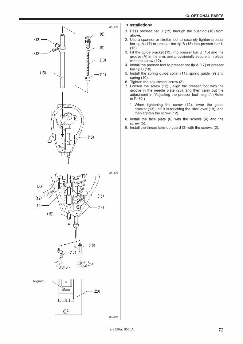
Z-8550A, 8560A
13. OPTIONAL PARTS
72
<Installation> 1. Pass presser bar U (15) through the bushing (16) from
above. 2. Use a spanner or similar tool to securely tighten presser
bar tip A (17) or presser bar tip B (18) into presser bar U (15).
3. Fit the guide bracket (13) into presser bar U (15) and the groove (A) in the arm, and provisionally secure it in place with the screw (12).
4. Install the presser foot to presser bar tip A (17) or presser bar tip B (18).
5. Install the spring guide collar (11), spring guide (9) and spring (10).
6. Tighten the adjustment screw (8). 7. Loosen the screw (12) , align the presser foot with the
groove in the needle plate (20), and then carry out the adjustment in “Adjusting the presser foot height”. (Refer to P. 62.) * When tightening the screw (12), lower the guide
bracket (13) until it is touching the lifter lever (19), and then tighten the screw (12).
8. Install the face plate (6) with the screws (4) and the screw (5).
9. Install the thread take-up guard (3) with the screws (2).
Aligned
3550M
3815M
3816M
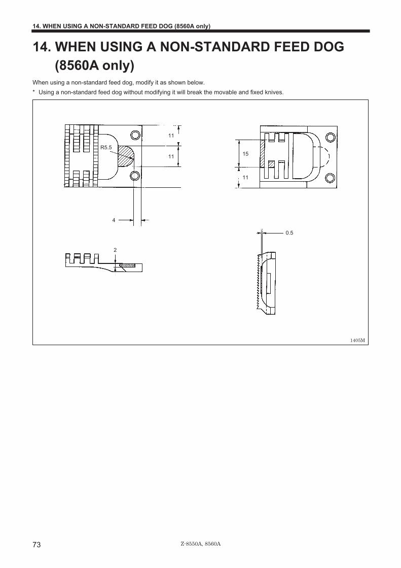
Z-8550A, 8560A
14. WHEN USING A NON-STANDARD FEED DOG (8560A only)
73
14. WHEN USING A NON-STANDARD FEED DOG (8560A only)
When using a non-standard feed dog, modify it as shown below. * Using a non-standard feed dog without modifying it will break the movable and fixed knives.
1405M
0.5
15R5.5
11
11
11
4
2
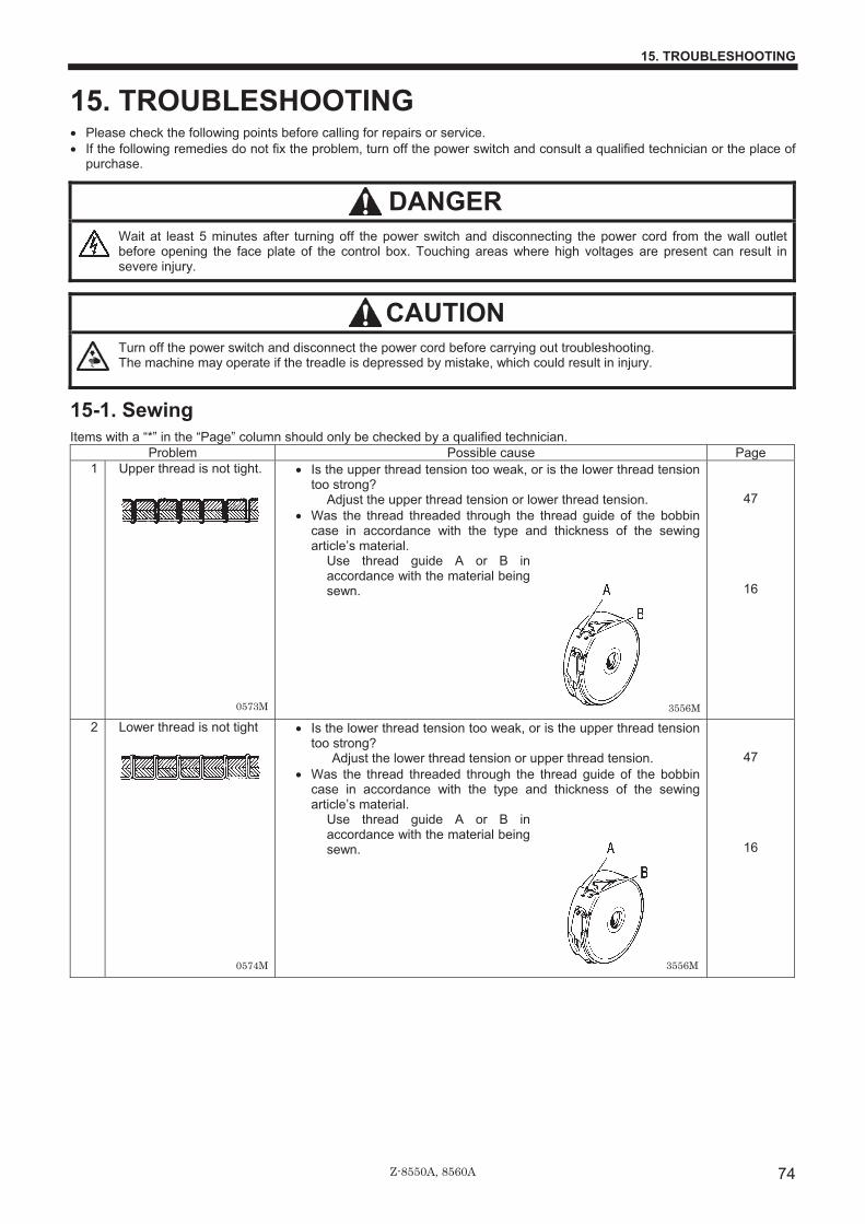
Z-8550A, 8560A
15. TROUBLESHOOTING
74
15. TROUBLESHOOTING • Please check the following points before calling for repairs or service. • If the following remedies do not fix the problem, turn off the power switch and consult a qualified technician or the place of
purchase.
DANGER Wait at least 5 minutes after turning off the power switch and disconnecting the power cord from the wall outlet
before opening the face plate of the control box. Touching areas where high voltages are present can result in severe injury.
CAUTION Turn off the power switch and disconnect the power cord before carrying out troubleshooting.
The machine may operate if the treadle is depressed by mistake, which could result in injury.
15-1. Sewing Items with a “*” in the “Page” column should only be checked by a qualified technician.
Problem Possible cause Page 1 Upper thread is not tight. • Is the upper thread tension too weak, or is the lower thread tension
too strong? Adjust the upper thread tension or lower thread tension.
• Was the thread threaded through the thread guide of the bobbin case in accordance with the type and thickness of the sewing article’s material.
Use thread guide A or B in accordance with the material being sewn.
47
16
2 Lower thread is not tight • Is the lower thread tension too weak, or is the upper thread tension too strong?
Adjust the lower thread tension or upper thread tension. • Was the thread threaded through the thread guide of the bobbin
case in accordance with the type and thickness of the sewing article’s material.
Use thread guide A or B in accordance with the material being sewn.
47
16
0573M
0574M
3556M
3556M

Z-8550A, 8560A
15. TROUBLESHOOTING
75
Problem Possible cause Page
3 Skipped stitches occur while sewing
• Is the needle tip bent? Is the needle tip blunt? If the needle tip is bent or broken, replace the needle.
• Is the needle properly installed? If it is incorrect, install the needle correctly.
• Is the machine properly threaded? If it is incorrect, thread the thread correctly.
• Is the presser foot pressure too weak? Adjust the presser foot pressure.
• Is the needle too thin? Replace the needle with a needle that is one rank thicker.
• Is the presser foot too high? Adjust the height of the presser foot.
• Is the needle and rotary hook timing incorrect? Adjust the height of the needle bar. Adjust the clearance between the needle and the rotary hook.
• Is the thread take-up spring too weak? Adjust the tension of the thread take-up spring.
15
17
48
62*
64* 64-65*
61*
4 Flattened zigzags appear in the stitch during intermittent sewing (8550A)
• Has the treadle been depressed backward? Do not press the treadle backward when the sewing machine is stopped. (When memory switch no. 109 is set to “1”, needle zigzagging also occurs when the treadle is depressed backward, in order to prevent a flattened zigzag from being sewn if the treadle is depressed backward by mistake.)
• Does the treadle move too easily when it is depressed backward? Adjust the force required to depress the treadle backward so that it is a bit heavier.
*
67*
5 Skipped stitches at sewing start Thread unravelling at sewing start
• Is the thread take-up spring tension too strong? Reduce the tension of the thread take-up spring.
• Is the thread take-up spring operating range too large? Lower the position of the thread take-up spring.
• Is the needle too thick? Try using a needle with a count that is one lower than the current needle.
<8550A> • Is the needle bar at the needle up stop position at the sewing start?
Set the needle bar to the needle up stop position at the sewing start.
• Is the length of the upper thread trailing from the needle hole too short?
Pull about 50 mm of thread through the needle hole at the sewing start.
<8560A> • Is the trailing length of the upper thread too short after thread
trimming? Adjust the upper thread feeding device.
• Are the threads not being trimmed cleanly? Sharpen the fixed knife with a whetstone, or replace the fixed knife. Replace the movable knife.
• Is the length of thread trailing out from the bobbin case after thread trimming too short?
If the bobbin is spinning loosely, replace the anti-spin spring in the bobbin case. Adjust the tension of the lower thread presser spring.
• Is the needle up stop position too high? Adjust the needle up stop position.
• Is the sewing speed too fast at the sewing start? Use the slow start feature.
61*
61*
40*
17
69*
55*
15 69*
41*
40*
0621M
1406M
0623M
Upper thread
0622M

Z-8550A, 8560A
15. TROUBLESHOOTING
76
Problem Possible cause Page
6 Uneven seam
• Is the presser foot pressure too weak? Adjust the presser foot pressure.
• Is the feed dog too low? Adjust the feed dog height.
• Is the bobbin scratched? If the bobbin is damaged, smooth it with an oiled grindstone or replace it.
48
62*
7 Horizontal thread tighten- ing not balanced
• Is the upper thread tension or lower thread tension too strong or too weak?
Adjust the upper thread tension or lower thread tension. • Does the rotary disc rotate smoothly?
Adjust the pre-tension. • Is the tension of the thread take-up spring correct?
Adjust the tension of the thread take-up spring. • Is the operating range of the thread take-up spring correct?
Adjust the position of the thread take-up spring. • Is the needle and rotary hook timing incorrect?
Adjust the height of the needle bar. Adjust the clearance between the needle and the rotary hook.
• Is the thread too thick for the needle? Use the correct needle or the correct thread.
• Is the rotary hook, bobbin case, thread take-up lever or some other part in the thread path damaged?
Repair the damage, or replace the part with a new one.
47
47
61*
61*
64* 64-65*
*
8 Large degree of puckering(excess tension)
• Is the upper thread tension too strong? Make the upper thread tension as weak as possible.
• Is the lower thread tension too strong? Make the lower thread tension as weak as possible.
• Is the point of the needle broken? If the point of the needle is broken, replace the needle.
• Is the needle too thick? Replace with as thin a needle as possible.
• Are the thread take-up spring tensions too strong? Make the thread take-up spring tension as weak as possible.
• Is the thread take-up spring operating range too large? Lower the position of the thread take-up spring to as low a position as possible.
• Is the presser foot pressure too strong? Adjust the presser foot pressure.
• Is the sewing speed too fast? Use the sewing speed control keys to gradually reduce the sewing speed.
• Is the angle of the feed dog incorrect? Tilt the front of the feed dog down slightly.
47
47
61*
61*
48
22
63*
0625M
0626M
Upper thread
Lower thread
0627M

Z-8550A, 8560A
15. TROUBLESHOOTING
77
Problem Possible cause Page
9 Lower thread is tangled at the sewing start. Spinning of bobbin during thread trimming
• Is the bobbin spinning direction correct when the lower thread is being pulled?
Set the bobbin so that it turns in the opposite direction to the rotary hook.
• Is there too much thread wound onto the bobbin?
The bobbin winding amount should not be more that 80 %.
• Is the anti-spin spring attached? (8560A) Attach the anti-spin spring.
• Is the bobbin turning smoothly? If the bobbin is not turning smoothly, replace the bobbin.
• Is a bobbin other that the light-alloy bobbins specified by Brother being used? (8560A)
Use only bobbins which are specified by Brother.
16
16
15
15
10 Upper and lower threads are breaking.
• Is the needle bent or is the needle tip broken? Replace the needle if it is bent or broken.
• Is the needle properly installed? If it is incorrect, install the needle correctly.
• Is the machine properly threaded? If it is incorrect, thread the thread correctly.
• Is the rotary hook sufficiently lubricated? If the oil gauge is down to the lower reference line in the oil gauge window, add more oil.
• Is the upper or lower thread tension too weak or too strong? Adjust the upper thread or lower thread tension.
• Is the upper thread may be loose because the thread take-up spring operating range is too small?
Adjust the position of the thread take-up spring. • Is the needle and rotary hook timing incorrect?
Adjust the height of the needle bar. Adjust the clearance between the needle and the rotary hook.
• Is the thread too thick for the needle? Use the correct needle or the correct thread.
• Is the rotary hook, bobbin case, thread take-up lever or some other part in the thread path damaged?
Repair the damage, or replace the part with a new one.
15
17 9
47
61*
64* 64-65*
*
11 Broken needles
• Is the material being pushed or pulled with excessive force during sewing?
• Is the needle properly installed? If it is incorrect, install the needle correctly.
• Is the needle bent, is the needle tip broken, or is the needle hole blocked?
Replace the needle. • Is the needle and rotary hook timing incorrect?
Adjust the height of the needle bar. Adjust the clearance between the needle and the rotary hook.
• It is extremely dangerous to leave any pieces of broken needle sticking in the material. If the needle breaks, search for all pieces until the whole of the needle is found again.�
• Furthermore, we recommend that through steps be taken to account for such needles to comply with product liability regulations.�
15
64* 64-65*
Lower thread
0628M 3557M
0471M
Caution
0469M

Z-8550A, 8560A
15. TROUBLESHOOTING
78
Problem Possible cause Page
12 Incorrect thread trimming (8560A) (Upper and lower threads are both not being trimmed)
• Is the fixed knife or movable knife damaged or worn? Replace the fixed knife or the movable knife.
• Is the thread trimming timing incorrect? Adjust the rotating direction of the thread trimming cam.
55*
68*
13 Incorrect thread trimming (8560A) (Upper thread or lower thread is not being trimmed)
• Is the needle properly installed? If it is incorrect, install the needle correctly.
• Is the fixed knife or movable knife blunt? Replace the fixed knife or the movable knife.
• Do skipped stitches occur during sewing? Refer to “Skipped stitches during sewing”.
15
55*
77*
14 The thread wiper does not wipe the thread. (8560A)
• Is the length of thread trailing from the needle hole too long after thread trimming?
Adjust the upper thread feeding device.
69*
15 Oil gauge (1) is not visible in oil gauge window.
• Is the oil tank empty? Fill the oil tank with oil.
9
16 Machine does not operate at high speed.
• Is the sewing speed setting or backtack speed setting incorrect? Use the sewing speed control keys to set the high speed.
22
17 Machine stops during sewing.
• Is the fixed stitch key turned on? Press the fixed stitch key so that the indicator turns off.
• Is the power supply voltage too low? Check the power supply. (If the power cord is too long or too many appliances are being run from a single outlet, this may cause voltage drops which will in turn cause the reset function to activate and stop the machine, even if the power supply itself is normal.)
37 *
18 Nothing appears on the
operation panel display. • Is the operation panel
connector 8P inside the control box disconnected?
Insert the connector securely.
11*
19 “GrEASEUP” flashes on the operation panel when the power is turned on.
• This display is to notify you that it is time to apply grease. Apply grease.
52
2195M
3558M

Z-8550A, 8560A
15. TROUBLESHOOTING
79
15-2. Error code displays 1. Make a note of the error code and then turn off the power. 2. After the operation panel display has turned off, eliminate the cause of the error and then
turn the power back on.
��Items with a “ * ” in the “Page” column should only be checked by a qualified technician. ��For items with “ ** ” appearing in the “Page” column, ask the place of purchase for advice.
Error code Possible cause Page
Err 50 (Safety switch operated)�
• Is the machine connector 14P inside the control box disconnected?
Insert the connector securely.
• Is the machine head tilted back? Return the machine head to its normal position.
11*
Err 65 (Panel key problem)
• Was the power switch turned on while a key on the operation panel was being pressed? Alternatively, there may be a malfunction of the operation panel that makes it seem like a key is still being pressed.
Press the power switch once more and check the operation panel. If the error still appears, contact the place of purchase.
*
Err 90 (Treadle unit not connected)�
• Is the treadle unit connector 4P inside the control box disconnected?
Insert the connector securely.
*
Err 91 (Treadle pedal position error)
• The settings in “Setting method for standard depression stroke” may be incorrect. Redo the settings in “Setting method for standard depression stroke”.
• Problem with treadle unit. Replace the treadle unit.
*
**
Err 95 (Treadle error)�
• Was the power turned on while the treadle was still depressed? Return the treadle to the neutral position, and then turn on the power switch.
Err 100 (GrEASEUP)
• This appears on the display when the sewing machine has continued to be used for a certain period after the “GREASEUP” notification appears without the grease being applied (without the reset procedure being carried out).
Apply grease and then carry out the reset procedure.
52*
3559M
3560M
3561M

Z-8550A, 8560A
15. TROUBLESHOOTING
80
Error code Possible cause Page
Err 101 (diP SW 4)
• Is DIP switch No.4 inside the control box set to ON?
Set DIP switch No.4 to OFF.
*
Err 111 (Needle up stop error)
• This appears on the display if the needle bar does not stop at the needle up stop position after the thread has been trimmed.
Check that the 14-pin encoder connector inside the control box is disconnected. Turn off the power and then turn the machine pulley by hand and check that it turns easily. Check that the thread is not tangled around the rotary hook or the thread trimming knife unit. Check if there is a problem with the thread trimming mechanism.
11* *
Err 130 (Sewing machine motor lock)
• Is the motor connector 4P disconnected from the control box?
Insert the connector securely.
• Has the machine locked up? Turn off the power and then turn the machine pulley by hand and check that it turns easily.
11*
Err 131 (Upper shaft encoder not connected)
• Is the encoder connector 14P inside the control box disconnected?
Insert the connector securely.
11*
3562M
3563M
3564M
3564M

Z-8550A, 8560A
15. TROUBLESHOOTING
81
Err 132 (Problem with sewing machine motor operation)
• Is the 14-pin encoder connector inside the control box disconnected?
Insert the connector securely.
• Problem with power P.C. board. Replace the control box.
11*
**
Err 150 (Sewing machine motor overheating abnormally)
• This appears on the display when the sewing machine motor becomes abnormally hot and the temperature protection has activated.
After the temperature has dropped, turn the power switch back on and operate the sewing machine as normal.
• Problem with sewing machine motor. Replace the sewing machine motor.
**
Err 151 (Problem with sewing machine motor overheating sensor)
• Is connector CN5 inside the sewing machine motor disconnected?
Insert the connector securely.
*
Err 190 (Over time)�
• This appears on the display when the sewing machine has been operating continuously for 3 minutes or more.
Turn the power switch off and then back on again, and then operate the sewing machine normally.
Err 191 (Thread trimming overtime error: 8560A)�
• This appears on the display if the needle bar does not move to the needle up stop position after the treadle is depressed backward.
Check that the thread is not tangled around the rotary hook or the knife unit. Check if there is a problem with the thread trimming mechanism.
*
Err 200 (Zigzag home position error)
• Is the 5-pin zigzag motor encoder connector or the 5-pin zigzag motor connector inside the control box disconnected?
Insert the connector securely.
11*
3565M
3564M
3116M
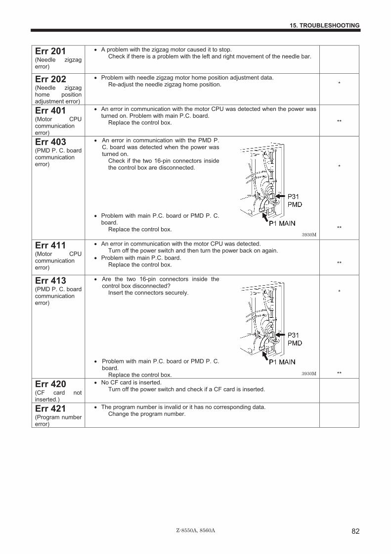
Z-8550A, 8560A
15. TROUBLESHOOTING
82
Err 201 (Needle zigzag error)
• A problem with the zigzag motor caused it to stop. Check if there is a problem with the left and right movement of the needle bar.
Err 202 (Needle zigzag home position adjustment error)
• Problem with needle zigzag motor home position adjustment data. Re-adjust the needle zigzag home position.
*
Err 401 (Motor CPU communication error)
• An error in communication with the motor CPU was detected when the power was turned on. Problem with main P.C. board.
Replace the control box.
**
Err 403 (PMD P. C. board communication error)
• An error in communication with the PMD P. C. board was detected when the power was turned on.
Check if the two 16-pin connectors inside the control box are disconnected.
• Problem with main P.C. board or PMD P. C. board.
Replace the control box.
*
**
Err 411 (Motor CPU communication error)
• An error in communication with the motor CPU was detected. Turn off the power switch and then turn the power back on again.
• Problem with main P.C. board. Replace the control box.
**
Err 413 (PMD P. C. board communication error)
• Are the two 16-pin connectors inside the control box disconnected?
Insert the connectors securely.
• Problem with main P.C. board or PMD P. C. board.
Replace the control box.
*
**
Err 420 (CF card not inserted.)
• No CF card is inserted. Turn off the power switch and check if a CF card is inserted.
Err 421 (Program number error)
• The program number is invalid or it has no corresponding data. Change the program number.
3930M
3930M

Z-8550A, 8560A
15. TROUBLESHOOTING
83
Error code Possible cause Page
Err 422 (CF card read error)
• Error occurred while reading CF card. Check the data on the CF card.
*
Err 424 (No free space on CF card)
• Insufficient free space on CF card. Use a different CF card.
Err 425 (CF card write error)
• Error occurred while writing to CF card. Use the specified type of CF card.
Err 430 (Flash memory error)
• Problem with flash memory on main P.C. board. Replace the control box.
**
Err 440 (EEPROM write error)
• Data cannot be backed up to the EEPROM on the main P. C. board. Replace the control box.
**
Err 441 (EEPROM read error)
• Data cannot be read from the EEPROM on the main P. C. board. Replace the control box.
**
Err 442 (EEPROM data error)
• Corrupt data in the EEPROM was initialized when the power was turned on. Turn off the power switch and then turn the power back on again.
Err 450 (Problem with machine head memory)
• Model selection could not been loaded from the machine head memory in the head detector unit.
Turn off the power switch and contact the place of purchase.
**
Err 452 (Machine head memory error)
• Is the 7-pin head detector unit connector inside the control box disconnected?
Insert the connector securely.
11*
Err 510 (Problem with sewing data)
• Invalid code in sewing data. For additional data, re-read the data from the CF card.
Err 512 (Number of stitches in sewing data is too great.)
• Number of stitches exceeds allowed maximum. Edit the sewing data so that it contains 500 stitches or less.
**
3566M

Z-8550A, 8560A
15. TROUBLESHOOTING
84
Error code Possible cause Page
Err 700 (Overvoltage)�
• Does the power supply voltage match the control box voltage specifications?
Check the voltage.
Err 701 (Sewing machine motor overvoltage)
• Abnormal rise in sewing machine motor drive voltage. Turn off the power switch and check the voltage.
*
Err 705 (Under voltage)
• Abnormal drop in power supply voltage. Check the input voltage.
*
Err 710 (Overcurrent)�
• Is the 9-pin or 11-pin connector inside the control box disconnected?
Insert the connector securely.
*
Err 711 (Needle zigzag motor overcurrent)
• Problem with PMD P.C. board. Replace the control box.
**
Err 740 (Cooling fan problem)
• The cooling fan (1) inside the control box is not working.
Check if it is blocked with thread scraps.
• Is the 3-pin connector inside the control box disconnected?
Insert the connector securely.
* *
3567M
Voltage rating label
3568M
3570M
3569M

Z-8550A, 8560A
15. TROUBLESHOOTING
85
Error code Possible cause Page
Err 790 (Solenoid power supply error)
• Is the solenoid fuse (8 A) inside the control box blown?
Replace the fuse.
*
Err 791 (Solenoid overcurrent)
• This is displayed when there is overcurrent in any of the solenoids (thread trimming, thread wiping, upper thread feeding, quick reverse or presser lifter).
Check the resistances of the solenoids. • Problem with main P.C. board.
Replace the control box.
**
**
If an error code that is not listed above appears or if carrying out the specified remedy does not solve the problem, contact the place of purchase.
3931M

Z-8550A, 8560A
MEMO
86

INSTRUCTION MANUAL 15-1, Naeshiro-cho, Mizuho-ku, Nagoya 467-8561, Japan. Phone: 81-52-824-2177
© 2005-2007 Brother Industries, Ltd. All Rights Reserved. Z-8550A ,8560ASA6035-201 E2007.10. B (1)
http://www.brother.com/