yzh-affinity-heat-pump-install-manual.pdf
TRANSCRIPT

501055-UIM-B-1009
R-410AOUTDOOR SPLIT-SYSTEM HEAT PUMP
MODELS: 18 SEER - YZH, HC8B, HL8B SERIES2 TO 5 TONS
INSTALLATION MANUALLISTED
ISO 9001Certified Quality
Management System
TABLE OF CONTENTSGENERAL . . . . . . . . . . . . . . . . . . . . . . . . . . . . . . . . . . . . . . . . . . . . . .1SAFETY . . . . . . . . . . . . . . . . . . . . . . . . . . . . . . . . . . . . . . . . . . . . . . . .1UNIT INSTALLATION . . . . . . . . . . . . . . . . . . . . . . . . . . . . . . . . . . . . .3SECTION IV: TXV INSTALLATIONS . . . . . . . . . . . . . . . . . . . . . . . . .6ELECTRICAL CONNECTIONS . . . . . . . . . . . . . . . . . . . . . . . . . . . . . .6
EVACUATION . . . . . . . . . . . . . . . . . . . . . . . . . . . . . . . . . . . . . . . . . 15SYSTEM CHARGE . . . . . . . . . . . . . . . . . . . . . . . . . . . . . . . . . . . . . 15SYSTEM OPERATION . . . . . . . . . . . . . . . . . . . . . . . . . . . . . . . . . . . 16INSTRUCTING THE OWNER . . . . . . . . . . . . . . . . . . . . . . . . . . . . . 16WIRING DIAGRAM . . . . . . . . . . . . . . . . . . . . . . . . . . . . . . . . . . . . . 18
LIST OF FIGURESTypical Installation with Required Clearances . . . . . . . . . . . . . . . . . . .3Tubing Hanger . . . . . . . . . . . . . . . . . . . . . . . . . . . . . . . . . . . . . . . . . . .4Underground Installation . . . . . . . . . . . . . . . . . . . . . . . . . . . . . . . . . . .4Heat Protection . . . . . . . . . . . . . . . . . . . . . . . . . . . . . . . . . . . . . . . . . .4Typical Field Wiring . . . . . . . . . . . . . . . . . . . . . . . . . . . . . . . . . . . . . . .6Communications Harness Connection . . . . . . . . . . . . . . . . . . . . . . . . .6CFM Selection Board . . . . . . . . . . . . . . . . . . . . . . . . . . . . . . . . . . . . . .7Communicating HP with Communicating Air Handler or Furnace . . . .7Communicating HP with Non-Communicating Air Handler or Furnace using Communicating Interface Control . . . . . . . . . . . . . . . . .7Thermostat Wiring – Two-Stage Heat Pumps - Two-Stage Variable Speed Furnaces . . . . . . . . . . . . . . . . . . . . . . . . .8
Thermostat Wiring – Two-Stage Heat Pumps - Two-Stage Variable Speed Furnaces . . . . . . . . . . . . . . . . . . . . . . . . . 9Thermostat Wiring – Two-Stage Heat Pumps - Variable Speed Air Handler . . . . . . . . . . . . . . . . . . . . . . . . . . . . . . . 10Thermostat Wiring – Two-Stage Heat Pumps - Variable Speed Air Handler . . . . . . . . . . . . . . . . . . . . . . . . . . . . . . . 11Thermostat Wiring – Two-Stage Heat Pumps - Variable Speed Modulating Furnaces . . . . . . . . . . . . . . . . . . . . . . . . 12Thermostat Wiring – Two-Stage Heat Pumps - Variable Speed Modulating Furnaces . . . . . . . . . . . . . . . . . . . . . . . . 13Heat Pump Flow Diagram . . . . . . . . . . . . . . . . . . . . . . . . . . . . . . . . . 14Wiring Diagram . . . . . . . . . . . . . . . . . . . . . . . . . . . . . . . . . . . . . . . . . 16
LIST OF TABLESDefrost Initiate Curves . . . . . . . . . . . . . . . . . . . . . . . . . . . . . . . . . . . .15 R-410A Saturation Properties . . . . . . . . . . . . . . . . . . . . . . . . . . . . . . 15
SECTION I: GENERALThe outdoor units are designed to be connected to a matching indoorcoil with sweat connect lines. Sweat connect units are factory chargedwith refrigerant for the smallest rated indoor coil plus 15 feet of fieldsupplied lines.
Matching indoor coils are available with a thermal expansion valve oran orifice liquid feed sized for the most common usage. The orifice sizeand/or refrigerant charge may need to be changed for some indoor-out-door unit combinations, elevation differences or total line lengths. Referto Application Data covering “General Piping Recommendations andRefrigerant Line Length” (Part Number 247077).
SECTION II: SAFETYThis is a safety alert symbol. When you see this symbol onlabels or in manuals, be alert to the potential for personalinjury.
Understand and pay particular attention to the signal words DANGER,WARNING, or CAUTION.
DANGER indicates an imminently hazardous situation, which, if notavoided, will result in death or serious injury.
WARNING indicates a potentially hazardous situation, which, if notavoided, could result in death or serious injury.
CAUTION indicates a potentially hazardous situation, which, if notavoided may result in minor or moderate injury. It is also used toalert against unsafe practices and hazards involving only property dam-age.
Improper installation may create a condition where the operation ofthe product could cause personal injury or property damage.Improper installation, adjustment, alteration, service or mainte-nance can cause injury or property damage. Refer to this manualfor assistance or for additional information, consult a qualified con-tractor, installer or service agency.
This product must be installed in strict compliance with theenclosed installation instructions and any applicable local, state,and national codes including, but not limited to building, electrical,and mechanical codes.
R-410A systems operate at higher pressures than R-22 systems.Do not use R-22 service equipment or components on R-410Aequipment. Service equipment Must Be Rated for R-410A.

501055-UIM-B-1009
2 Johnson Controls Unitary Products
INSPECTIONAs soon as a unit is received, it should be inspected for possible dam-age during transit. If damage is evident, the extent of the damageshould be noted on the carrier’s delivery receipt. A separate request forinspection by the carrier’s agent should be made in writing. See LocalDistributor for more information.
Requirements For Installing/Servicing R-410A Equipment• Gauge sets, hoses, refrigerant containers, and recovery system
must be designed to handle POE oils, and the higher pressuresof R-410A.
• Manifold sets should be 800 PSIG high side and 250 PSIG lowside with 550 PSIG low side restart.
• All hoses must have a 700 PSIG service pressure rating.
• Leak detectors should be designed to detect HFC refrigerant.
• Recovery equipment (including refrigerant recovery containers)must be specifically designed to handle R-410A.
• Do not use an R-22 TXV.
• A liquid-line filter drier is required on every unit.
LIMITATIONSThe unit should be installed in accordance with all National, State andLocal Safety Codes and the limitations listed below:
1. Limitations for the indoor unit, coil and appropriate accessoriesmust also be observed.
2. The outdoor unit must not be installed with any duct work in the airstream. The outdoor fan is the propeller type and is not designed tooperate against any additional external static pressure.
3. The maximum and minimum conditions for operation must beobserved to assure a system that will give maximum performancewith minimum service.
4. This unit is not designed to operate with a low ambient kit. Do notmodify the control system to operate with any kind of low ambientkit.
5. The maximum allowable line length for this product is 75 feet.
SECTION III: UNIT INSTALLATIONLOCATIONBefore starting the installation, select and check the suitability of thelocation for both the indoor and outdoor unit. Observe all limitations andclearance requirements.
The outdoor unit must have sufficient clearance for air entrance to thecondenser coil, for air discharge and for service access. See Figure 1.
NOTE: For multiple unit installations, units must be spaced a minimumof 18 inches apart. (Coil face to coil face.)
If the unit is to be installed on a hot sun exposed roof or a black-toppedground area, the unit should be raised sufficiently above the roof orground to avoid taking the accumulated layer of hot air into the outdoorunit.
Provide an adequate structural support.
ADD-ON REPLACEMENT/RETROFITWhen this unit is being used as a replacement for an R-22 unit, it isrequired that the outdoor unit, indoor coil, and metering device all bereplaced. The following steps should be performed in order to insureproper system operation and performance. Line-set change out is alsorecommended.
1. Change-out of the indoor coil to an approved R-410A coil/ condens-ing unit combination with the appropriate metering device.
2. Change-out of the line-set when replacing an R-22 unit with anR410-A unit is highly recommended to reduce cross-contaminationof oils and refrigerants.
3. If change-out of the line set is not practical, then the following pre-cautions should be taken.
• Inspect the line set for kinks, sharp bends, or other restrictions,and for corrosion.
• Determine if there are any low spots which might be serving asoil traps.
• Flush the line set with a commercially available flush kit toremove as much of the existing oil and contaminants as possi-ble.
• Install a suction line filter-drier to trap any remaining contami-nants, and remove after 50 hours of operation.
4. If the outdoor unit is being replaced due to a compressor burnout,then installation of a 100% activated alumina suction-line filter drierin the suction-line is required, in addition to the factory installed liq-uid-line drier. Operate the system for 10 hours. Monitor the suctiondrier pressure drop. If the pressure drop exceeds 3 psig, replaceboth the suction-line and liquid-line driers. After a total of 10 hoursrun time where the suction-line pressure drop has not exceeded 3psig, replace the liquid line drier, and remove the suction-line drier.Never leave a suction-line drier in the system longer than 50 hoursof run time.
AIR TEMPERATURE DB AT OUTDOOR COIL, °F
AIR TEMPERATURE AT INDOOR COIL, °F
Min. Max. Min. Max.
Cool Heat Cool HeatWB Cool
DB Heat
WB Cool
DB Heat
50 -10 115 75 57 501
1. Operation below this temperature is permissible for a short period of time, during morning warm-up.
72 80
501055-UIM-B-1009
Johnson Controls Unitary Products 3
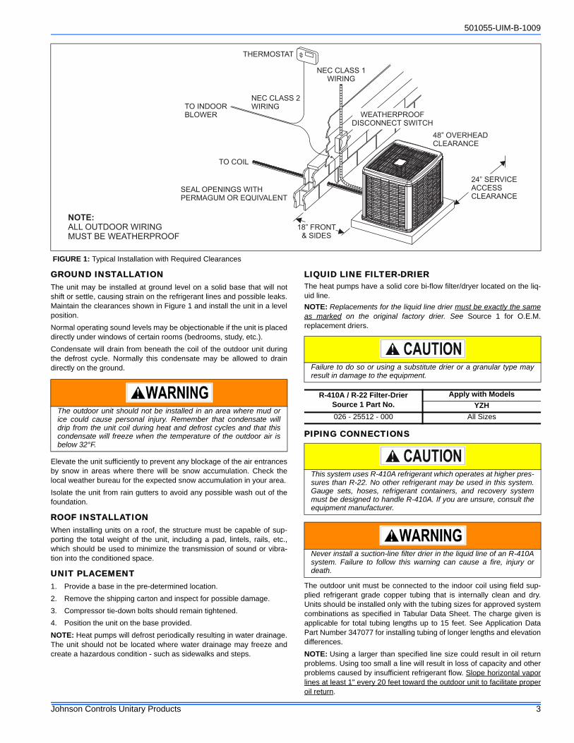
GROUND INSTALLATIONThe unit may be installed at ground level on a solid base that will notshift or settle, causing strain on the refrigerant lines and possible leaks.Maintain the clearances shown in Figure 1 and install the unit in a levelposition.
Normal operating sound levels may be objectionable if the unit is placeddirectly under windows of certain rooms (bedrooms, study, etc.).
Condensate will drain from beneath the coil of the outdoor unit duringthe defrost cycle. Normally this condensate may be allowed to draindirectly on the ground.
Elevate the unit sufficiently to prevent any blockage of the air entrancesby snow in areas where there will be snow accumulation. Check thelocal weather bureau for the expected snow accumulation in your area.
Isolate the unit from rain gutters to avoid any possible wash out of thefoundation.
ROOF INSTALLATIONWhen installing units on a roof, the structure must be capable of sup-porting the total weight of the unit, including a pad, lintels, rails, etc.,which should be used to minimize the transmission of sound or vibra-tion into the conditioned space.
UNIT PLACEMENT1. Provide a base in the pre-determined location.
2. Remove the shipping carton and inspect for possible damage.
3. Compressor tie-down bolts should remain tightened.
4. Position the unit on the base provided.
NOTE: Heat pumps will defrost periodically resulting in water drainage.The unit should not be located where water drainage may freeze andcreate a hazardous condition - such as sidewalks and steps.
LIQUID LINE FILTER-DRIERThe heat pumps have a solid core bi-flow filter/dryer located on the liq-uid line.
NOTE: Replacements for the liquid line drier must be exactly the sameas marked on the original factory drier. See Source 1 for O.E.M.replacement driers.
PIPING CONNECTIONS
The outdoor unit must be connected to the indoor coil using field sup-plied refrigerant grade copper tubing that is internally clean and dry.Units should be installed only with the tubing sizes for approved systemcombinations as specified in Tabular Data Sheet. The charge given isapplicable for total tubing lengths up to 15 feet. See Application DataPart Number 347077 for installing tubing of longer lengths and elevationdifferences.
NOTE: Using a larger than specified line size could result in oil returnproblems. Using too small a line will result in loss of capacity and otherproblems caused by insufficient refrigerant flow. Slope horizontal vaporlines at least 1" every 20 feet toward the outdoor unit to facilitate properoil return.
FIGURE 1: Typical Installation with Required Clearances
THERMOSTAT
NEC CLASS 1
WIRING
TO INDOOR
BLOWER
NEC CLASS 2
WIRING
TO COIL
WEATHERPROOF
DISCONNECT SWITCH
48” OVERHEAD
CLEARANCE
24” SERVICE
ACCESS
CLEARANCE
18” FRONT
& SIDES
NOTE:
ALL OUTDOOR WIRING
MUST BE WEATHERPROOF
SEAL OPENINGS WITH
PERMAGUM OR EQUIVALENT
The outdoor unit should not be installed in an area where mud orice could cause personal injury. Remember that condensate willdrip from the unit coil during heat and defrost cycles and that thiscondensate will freeze when the temperature of the outdoor air isbelow 32°F.
Failure to do so or using a substitute drier or a granular type mayresult in damage to the equipment.
R-410A / R-22 Filter-DrierSource 1 Part No.
Apply with Models
YZH
026 - 25512 - 000 All Sizes
This system uses R-410A refrigerant which operates at higher pres-sures than R-22. No other refrigerant may be used in this system.Gauge sets, hoses, refrigerant containers, and recovery systemmust be designed to handle R-410A. If you are unsure, consult theequipment manufacturer.
Never install a suction-line filter drier in the liquid line of an R-410Asystem. Failure to follow this warning can cause a fire, injury ordeath.
501055-UIM-B-1009
4 Johnson Controls Unitary Products
PRECAUTIONS DURING LINE INSTALLATION1. Install the lines with as few bends as possible. Care must be taken
not to damage the couplings or kink the tubing. Use clean harddrawn copper tubing where no appreciable amount of bendingaround obstruction is necessary. If soft copper must be used, caremust be taken to avoid sharp bends which may cause a restriction.
2. The lines should be installed so that they will not obstruct serviceaccess to the coil, air handling system or filter.
3. Care must also be taken to isolate the refrigerant lines to minimizenoise transmission from the equipment to the structure.
4. The vapor line must be insulated with a minimum of 1/2" foam rub-ber insulation (Armaflex or equivalent). Liquid lines that will beexposed to direct sunlight and/or high temperatures must also beinsulated.
Tape and suspend the refrigerant lines as shown. DO NOT allow tubemetal-to-metal contact. See Figure 2.
5. Use PVC piping as a conduit for all underground installations asshown in Figure 3. Buried lines should be kept as short as possibleto minimize the build up of liquid refrigerant in the vapor line duringlong periods of shutdown
6. Pack fiberglass insulation and a sealing material such as perma-gum around refrigerant lines where they penetrate a wall to reducevibration and to retain some flexibility.
7. See Form 690.01-AD1V for additional piping information.
PRECAUTIONS DURING BRAZING OF LINESAll outdoor unit and evaporator coil connections are copper-to-copperand should be brazed with a phosphorous-copper alloy material suchas Silfos-5 or equivalent. DO NOT use soft solder. The outdoor unitshave reusable service valves on both the liquid and vapor connections.The total system refrigerant charge is retained within the outdoor unitduring shipping and installation. The reusable service valves are pro-vided to evacuate and charge per this instruction.
Serious service problems can be avoided by taking adequate precau-tions to assure an internally clean and dry system.
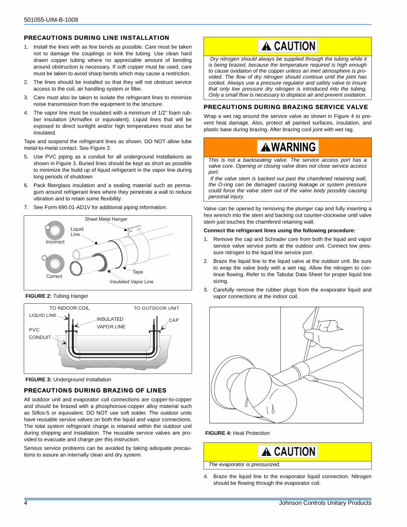
PRECAUTIONS DURING BRAZING SERVICE VALVEWrap a wet rag around the service valve as shown in Figure 4 to pre-vent heat damage. Also, protect all painted surfaces, insulation, andplastic base during brazing. After brazing cool joint with wet rag.
Valve can be opened by removing the plunger cap and fully inserting ahex wrench into the stem and backing out counter-clockwise until valvestem just touches the chamfered retaining wall.
Connect the refrigerant lines using the following procedure:
1. Remove the cap and Schrader core from both the liquid and vaporservice valve service ports at the outdoor unit. Connect low pres-sure nitrogen to the liquid line service port.
2. Braze the liquid line to the liquid valve at the outdoor unit. Be sureto wrap the valve body with a wet rag. Allow the nitrogen to con-tinue flowing. Refer to the Tabular Data Sheet for proper liquid linesizing.
3. Carefully remove the rubber plugs from the evaporator liquid andvapor connections at the indoor coil.
4. Braze the liquid line to the evaporator liquid connection. Nitrogenshould be flowing through the evaporator coil.
FIGURE 2: Tubing Hanger
FIGURE 3: Underground Installation
LiquidLine
Incorrect
CorrectTape
Sheet Metal Hanger
Insulated Vapor Line
TO INDOOR COIL TO OUTDOOR UNIT
LIQUID LINE
CAP
PVC
CONDUIT
INSULATED
VAPOR LINE
Dry nitrogen should always be supplied through the tubing while itis being brazed, because the temperature required is high enoughto cause oxidation of the copper unless an inert atmosphere is pro-vided. The flow of dry nitrogen should continue until the joint hascooled. Always use a pressure regulator and safety valve to insurethat only low pressure dry nitrogen is introduced into the tubing.Only a small flow is necessary to displace air and prevent oxidation.
This is not a backseating valve. The service access port has avalve core. Opening or closing valve does not close service accessport. If the valve stem is backed out past the chamfered retaining wall,the O-ring can be damaged causing leakage or system pressurecould force the valve stem out of the valve body possibly causingpersonal injury.
FIGURE 4: Heat Protection
The evaporator is pressurized.

501055-UIM-B-1009
Johnson Controls Unitary Products 5
5. Slide the grommet away from the vapor connection at the indoorcoil. Braze the vapor line to the evaporator vapor connection. Afterthe connection has cooled, slide the grommet back into originalposition. Refer to the Tabular Data Sheet for proper vapor line siz-ing.
6. Protect the vapor valve with a wet rag and braze the vapor line con-nection to the outdoor unit. The nitrogen flow should be exiting thesystem from the vapor service port connection. After this connec-tion has cooled, remove the nitrogen source from the liquid fittingservice port.
7. Replace the Schrader core in the liquid and vapor valves.
8. Go to “SECTION IV” for TXV installation.
9. Leak test all refrigerant piping connections including the serviceport flare caps to be sure they are leak tight. DO NOT OVER-TIGHTEN (between 40 and 60 inch - lbs. maximum).
10. Evacuate the vapor line, evaporator and the liquid line, to 500microns or less.
NOTE: Line set and indoor coil can be pressurized to 250 psig with drynitrogen and leak tested with a bubble type leak detector. Than releasethe nitrogen charge.
NOTE: Do not use the system refrigerant in the outdoor unit to purge orleak test.
11. Replace cap on service ports. Do not remove the flare caps fromthe service ports except when necessary for servicing the system.
12. Release the refrigerant charge into the system. Open both the liq-uid and vapor valves by removing the plunger cap and with an allenwrench back out counter-clockwise until valve stem just touches thechamfered retaining wall. See See - PRECAUTIONS DURINGBRAZING SERVICE VALVE.
13. Replace plunger cap finger tight, then tighten an additional 1/12turn (1/2 hex flat). Cap must be replaced to prevent leaks.
See "System Charge” section for checking and recording systemcharge.
SECTION IV: SECTION IV: TXV INSTALLATIONSThe following are the basic steps for installation. For detailed instruc-tions, refer to the Installation Instructions accompanying the TXV kit.
Install TXV kit as follows:
1. Relieve the holding charge by pulling off the rubber cap plug on thesuction manifold line of the coil.
2. After holding charge is completely discharged, loosen and removethe schraeder cap seal.
3. Loosen and remove distributor cap seal.
4. Install the thermal expansion valve to the orifice distributor assem-bly with supplied fittings. Hand tighten and turn an additional 1/4turn to seal. Do not overtighten fittings.
5. Install the liquid line to the top of the thermal expansion valve withfitting supplied with the liquid line. Hand modify the liquid line toalign with casing opening. Hand tighten the liquid line and an addi-tional 1/4 turn to seal.
6. Install the TXV equalizer line into the vapor line as follows:
a. Hand tighten the 1/4” SAE nut to the schraeder fitting and anadditional 1/3 turn to seal.
7. Install the TXV bulb to the vapor line near the equalizer line, usingthe bulb clamp(s) furnished with the TXV assembly. Ensure the bulbis making maximum contact.
a. Bulb should be installed on a horizontal run of the vapor line ifpossible. The bulb should be installed on top of the line.
b. If bulb installation is made on a vertical run, the bulb should belocated at least 16 inches from any bend, and on the tubingsides opposite the plane of the bend. The bulb should be posi-tioned with the bulb tail at the top, so that the bulb acts as a res-ervoir.
c. Bulb should be insulated using thermal insulation provided toprotect it from the effect of the surrounding ambient tempera-ture. Cover completely to insulate from air-stream.
All connections to be brazed are copper-to-copper and should bebrazed with a phosphorous-copper alloy material such as Silfos-5 orequivalent. DO NOT use soft solder.
Install the TXV bulb to the vapor line near the equalizer line, using thetwo bulb clamps furnished with the TXV assembly. Ensure the bulb ismaking maximum contact. Refer to TXV installation instruction for viewof bulb location.
SECTION V: ELECTRICAL CONNECTIONSGENERAL INFORMATION & GROUNDINGCheck the electrical supply to be sure that it meets the values specifiedon the unit nameplate and wiring label.
Power wiring, control (low voltage) wiring, disconnect switches and overcurrent protection must be supplied by the installer. Wire size should besized per NEC requirements.
The complete connection diagram and schematic wiring label is locatedon the inside surface of the unit service access panel and this instruc-tion.
Do not connect manifold gauges unless trouble is suspected.Approximately 3/4 ounce of refrigerant will be lost each time a stan-dard manifold gauge is connected.
Never attempt to repair any brazed connections while the system isunder pressure. Personal injury could result.
In all cases, mount the TXV bulb after vapor line is brazed and hashad sufficient time to cool.
Dry nitrogen should always be supplied through the tubing while itis being brazed, because the temperature required is high enoughto cause oxidation of the copper unless an inert atmosphere is pro-vided. The flow of dry nitrogen should continue until the joint hascooled. Always use a pressure regulator and safety valve to insurethat only low pressure dry nitrogen is introduced into the tubing.Only a small flow is necessary to displace air and prevent oxidation.
All field wiring must USE COPPER CONDUCTORS ONLY and bein accordance with Local, National Fire, Safety & Electrical Codes.This unit must be grounded with a separate ground wire in accor-dance with the above codes.

501055-UIM-B-1009
6 Johnson Controls Unitary Products
FIELD CONNECTIONS POWER WIRING1. Install the proper size weatherproof disconnect switch outdoors and
within sight of the unit.
2. Remove the screws at the bottom of the corner cover. Slide cornercover down and remove from unit. See Figure 5.
3. Run power wiring from the disconnect switch to the unit.
4. Remove the service access panel to gain access to the unit wiring.Route wires from disconnect through power wiring opening pro-vided and into the unit control box.
5. Install the proper size time-delay fuses or circuit breaker, and makethe power supply connections.
6. Energize the crankcase heater if equipped to save time by preheat-ing the compressor oil while the remaining installation is com-pleted.
FIELD CONNECTIONS CONTROL WIRING - CONVENTIONAL1. Route low voltage wiring into bottom of control box as shown in Fig-
ure 5. Make low voltage wiring connections inside the junction boxper Figures 10 - 15.
2. The complete connection diagram and schematic wiring label islocated on the inside surface of the unit service access panel.
3. Replace the corner cover and service access panel removed inSteps 2 and 4 of the “Field Connections Power Wiring” section.
NOTE: Ambient temperature sensor should extend below control boxby 1”.
4. All field wiring to be in accordance with national electrical codes(NEC) and/or local-city codes.
5. Mount the thermostat about 5 ft. above the floor, where it will beexposed to normal room air circulation. Do not place it on an out-side wall or where it is exposed to the radiant effect from exposedglass or appliances, drafts from outside doors or supply air grilles.
6. Route the 24-volt control wiring (NEC Class 2) from the outdoor unitto the indoor unit and thermostat.
NOTE: To eliminate erratic operation, seal the hole in the wall at thethermostat with permagum or equivalent to prevent air drafts affectingthe operation of in the thermostat.
FIELD CONNECTIONS CONTROL WIRING - COMMUNICATING1. The Communication Harness is provided with the communicating
thermostat.
2. Route low voltage four conductor shielded thermostat communica-tions harness into junction box and connect to communicationsport on control board. See Figure 6.
3. The complete connection diagram and schematic wiring label islocated on the inside surface of the unit service access panel.
4. Replace the corner cover and service access panel removed inSteps 2 and 4 of the “Field Connections Power Wiring” section.
NOTE: Ambient temperature sensor should extend below control boxby 1”.
5. Route the 24-volt control wiring (NEC Class 2) from the outdoor unitto the indoor unit and thermostat.
6. All field wiring to be in accordance with national electrical codes(NEC) and/or local-city codes.
7. Mount the thermostat about 5 ft. above the floor, where it will beexposed to normal room air circulation. Do not place it on an out-side wall or where it is exposed to the radiant effect from exposedglass or appliances, drafts from outside doors or supply air grilles.
NOTE: To eliminate erratic operation, seal the hole in the wall at thethermostat with permagum or equivalent to prevent air drafts affectingthe operation of in the thermostat.
FIGURE 5: Typical Field Wiring
Corner
Cover
Control
Wiring
Power
Wiring
Service
Access
Panel
Ambient
Temperature
Sensor
If unit is going to be setup as a communicating system, the conven-tional wiring must be removed from the Outdoor Control Board.
FIGURE 6: Communications Harness Connection
COMMUNICATIONS PORT CONTROL BOARD
COMMUNICATIONS
HARNESS
JUNCTION
BOX

501055-UIM-B-1009
Johnson Controls Unitary Products 7
DEHUMIDIFICATION CONTROLA dehumidification control accessory 2HU06700124 may be used withvariable speed air handlers or furnaces in high humidity areas. Thiscontrol works with the variable speed indoor unit to provide cooling at areduced air flow, lowering evaporator temperature and increasing latentcapacity. The humidistat in this control opens the humidistat contacts onhumidity rise. To install, refer to instructions packaged with the acces-sory and Figures 8 - 13. Prior to the installation of the dehumidificationcontrol, the jumper across the HUMIDISTAT terminals on the indoorvariable speed air handler or furnace CFM selection board must beremoved.
During cooling, if the relative humidity in the space is higher than thedesired set point of the dehumidification control, the variable speedblower motor will operate at lower speed until the dehumidification con-trol is satisfied. A 40-60% relative humidity level is recommended toachieve optimum comfort.
If a dehumidification control is installed, it is recommended that a mini-mum air flow of 325 cfm/ton be supplied at all times.
CFM SELECTION BOARD SETTINGS
For proper system operation the CFM Selection Board jumpers must beset properly.
Refer to the Tabular Data Sheet for the recommended air flow settingsfor each size condensing unit.
Set the cooling speed per the instructions for the air handler or furnaceby selecting the correct COOL and ADJ taps. Verify the airflow usingthe LED display on the CFM selection board.
The HUMIDISTAT jumper must also be removed if a dehumidistat isinstalled.
If installed as a communicating system (outdoor, indoor and thermo-stat), the system will automatically adjust to the optimal airflow settings.These parameters can also be modified using the communicating ther-mostat. Refer to the communicating thermostat owner’s manual for thisprocedure. Manual setting of the airflow jumpers on the ID equipmentis not necessary with the communicating thermostat.
FIGURE 7: CFM Selection Board
HE
AT
DE
LA
YC
OO
LA
DJU
ST
A B C D
A B C D
LE
D2
FIGURE 8: Communicating HP with Communicating Air Handler or Furnace
FIGURE 9: Communicating HP with Non-Communicating Air Handler or Furnace using Communicating Interface Control
R
C
Y1
Y2
Touch Control
Communicating
Control
Air Handler/Furnace
Communicating
Control
Heat Pump
Communicating
Control
GND
or C
GND
or C
B-
R
A+
GND
or C
GND
or C
B-
R
A+
GND
or C
GND
or C
B-
R
A+
R
C
Y1
Y2
HUM
W2
DHUM
W
G
C
R
O
Y
Y2
HUM
W2
DHUM
W
G
C
R
O
Y
Y2
Touch Control
Communicating
Control
Communicating
Indoor
Interface Control
Non-Communicating
Indoor Unit
Heat Pump
Communicating
Control
Wire per
non-comm.
installation
manual
Assume that
connections
are from
thermostat
GND
or C
GND
or C
B-
R
A+
GND
or C
GND
or C
B-
R
A+
GND
or C
GND
or C
B-
R
A+

501055-UIM-B-1009
8 Johnson Controls Unitary Products
FIGURE 10: Thermostat Wiring – Two-Stage Heat Pumps - Two-Stage Variable Speed Furnaces
HP 24A Two Stage Heat Pump – Two Stage Variable Speed Furnace (With Hot Heat Pump Operation)
OReversing Valve
Energized in Cool
C24 – Volt Common
R24 – Volt Hot
W1 OUTFirst Stage Heat
W2 OUTSecond Stage Heat
Y2 OUTSecond Stage Compressor
Y1Single Stage Compressor
X/LMalfunction Light
Y2Second Stage Compressor
WAuxiliary Heat
BSBonnet Sensor
BSGBonnet Sensor
TWO STAGEHEAT PUMP
Bonnet Sensor(Optional)
C24 – Volt Common
Y1First Stage Compressor
LMalfunction Light
Y2Second Stage Compressor
GFan
*PP32U71124*PP32U72124
THERMOSTAT
R24 – Volt Hot
E/W1First Stage Aux. Heat
W2Second Stage Aux. Heat
DHMDehumidistat
HMHumidistat
OReversing Valve
Energized in Cool
Change FFuel jumperon the heat pump control
to “ON”
Part Numbers:SAP = Legacy
126768 = 031-0913718395 = 031-01996340512 = 031-09178
1
1Part Numbers:SAP = Legacy
265904 = 031-09169
2
C24 – Volt Common
R24 – Volt Hot
Y1Single Stage Compressor
TWO STAGEVARIABLE SPEED
FURNACE CONTROL
GFan
TWO STAGEVARIABLE SPEED
FURNACE
W/W1First Stage Heat
Y/Y2 Second or Full
Stage Compressor
W2Second Stage Heat
OReversing Valve
X/LMalfunction Light
DHUMDehumidification
2
Move HEAT PUMPjumper to “YES”
Move DHUMjumper to “YES”
if humidistat is to be used.
PV(8/9)ID MODELS
(F/L)*(8/9)V
YORKGUARD VICONTROL
(G/L)(8/9)V
YZEOD MODELS
YZHH*5H*8
24VAC Humidifier(Optional)
Step 1 of the ThermostatInstaller Table must be
set to Heat Pump
E2/P Switch must be in theE2 position
Step 2 of the ThermostatInstaller Table must be
set to 2Step 5 of Thermostat UserConfiguration Menu must
be set to “ON” forDehumidification
Change Hot Heat Pumpjumper on the heat pump
control to “ON”

501055-UIM-B-1009
Johnson Controls Unitary Products 9
FIGURE 11: Thermostat Wiring – Two-Stage Heat Pumps - Two-Stage Variable Speed Furnaces
HP 24C Two Stage Heat Pump – Two Stage Variable Speed Furnace (With Hot Heat Pump Operation)
OReversing Valve
Energized in Cool
C24 – Volt Common
R24 – Volt Hot
W1 OUTFirst Stage Heat
W2 OUTSecond Stage Heat
Y2 OUTSecond Stage Compressor
Y1Single Stage Compressor
X/LMalfunction Light
Y2Second Stage Compressor
WAuxiliary Heat
BSBonnet Sensor
BSGBonnet Sensor
TWO STAGEHEAT PUMP
Bonnet Sensor(Optional)
Change FFuel jumperon the heat pump control
to “ON”
Part Numbers:SAP = Legacy
126768 = 031-0913718395 = 031-01996340512 = 031-09178
1
1Part Numbers:SAP = Legacy
265904 = 031-09169
2
C24 – Volt Common
R24 – Volt Hot
Y1Single Stage Compressor
TWO STAGEVARIABLE SPEED
FURNACE CONTROL
GFan
TWO STAGEVARIABLE SPEED
FURNACE
W/W1First Stage Heat
Y/Y2 Second or Full
Stage Compressor
W2Second Stage Heat
OReversing Valve
X/LMalfunction Light
DHUMDehumidification
2
Move HEAT PUMPjumper to “YES”
Move DHUMjumper to “YES”
if humidistat is to be used.
PV(8/9)ID MODELS
(F/L)*(8/9)V
YORKGUARD VICONTROL
(G/L)(8/9)V
YZEOD MODELS
YZHH*5H*8
C24 – Volt Common
R24 – Volt Hot
Y1First Stage Compressor
OReversing Valve
Energized in Cool
LMalfunction Light
Y2Second Stage Compressor
GFan
*DN22H00124*DP22U70124
THERMOSTAT
E/W1First Stage Aux. Heat
W2Second Stage Aux. Heat
C24 – Volt Common
YFirst Stage Compressor
O/BReversing Valve
LMalfunction Light
Y2Second Stage Compressor
GFan
*PP32U70124
THERMOSTAT
EEmergency Heat
R24 – Volt Hot(Heat XFMR)
RC24 – Volt Hot(Cool XFMR)
AUXAuxiliary Heat
Step 1 of ThermostatInstaller/Configuration
Menu must be set to “HP2”Selection of GAS/ELEC
switch on thermostat not necessary
Thermostat Installer Setup0170-System Type-must be set to 12
3 Heat/2 Heat PumpThermostat Installer Setup0190-Changeover Valve-
must be set to 0O/B terminal
Energized in CoolingThermostat Installer Setup0200-Backup Heat Source-
must be set to 1Heat Pump Backup Heat
Source is Fossil Fuel
External Humidistat(Optional)
Open on Humidity Rise
Thermostat Installer Setup0210-External Fossil Fuel
Kit- must be set to 1Heat Pump Control
is Controlling Heat PumpBackup Heat
Change Hot Heat Pumpjumper on the heat pump
control to “ON”
3
501055-UIM-B-1009
10 Johnson Controls Unitary Products
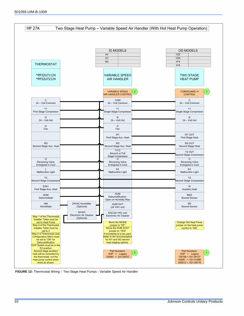
FIGURE 12: Thermostat Wiring – Two-Stage Heat Pumps - Variable Speed Air Handler
HP 27A Two Stage Heat Pump – Variable Speed Air Handler (With Hot Heat Pump Operation)
OReversing Valve
Energized in Cool
C24 – Volt Common
R24 – Volt Hot
W1 OUTFirst Stage Heat
W2 OUTSecond Stage Heat
Y2 OUTSecond Stage Compressor
Y1Single Stage Compressor
X/LMalfunction Light
Y2Second Stage Compressor
WAuxiliary Heat
BSBonnet Sensor
BSGBonnet Sensor
TWO STAGEHEAT PUMP
C24 – Volt Common
Y1First Stage Compressor
LMalfunction Light
Y2Second Stage Compressor
GFan
*PP32U71124*PP32U72124
THERMOSTAT
R24 – Volt Hot
E/W1First Stage Aux. Heat
W2Second Stage Aux. Heat
DHMDehumidistat
HMHumidistat
Step 1 of the ThermostatInstaller Table must be
set to Heat Pump
OReversing Valve
Energized in Cool
1
24VAC Humidifier(Optional)
Part Numbers:SAP = Legacy
159481 = 031-09157
2
COM24 – Volt Common
R24 – Volt Hot
W1First Stage Aux. Heat
W2Second Stage Aux. Heat
Y1Single Stage Compressor
Y/Y2Second or Full
Stage CompressorO
Reversing ValveEnergized in Cool
X/LMalfunction Light
HUMDehumidification-
Open on Humidity Rise
VARIABLE SPEEDAIR HANDLER CONTROL
GFan
Move the MODEjumper to “HP”
Move the HUM STATjumper to “YES”
if humidistat is to be used.
VARIABLE SPEEDAIR HANDLER
2
Part Numbers:SAP = Legacy
126768 = 031-0913718395 = 031-01996340512 = 031-09178
1
AVID MODELS
SVMV
YZEOD MODELS
YZHH*5
YORKGUARD VICONTROL
H*8
24VACElectronic Air Cleaner
(Optional)
E2/P Switch must be in theE2 position
Step 2 of the ThermostatInstaller Table must be
set to 2Step 5 of Thermostat UserConfiguration Menu must
be set to “ON” forDehumidification
EAC(24 VAC out)Electronic Air Cleaner
Refer to AH documentationfor W1 and W2 electricheat staging options.
HUM OUT(24 VAC out)
Second stage auxiliaryheat will be controlled by the thermostat, not the
heat pump control whenwired as shown.
Change Hot Heat Pumpjumper on the heat pump
control to “ON”

501055-UIM-B-1009
Johnson Controls Unitary Products 11
FIGURE 13: Thermostat Wiring – Two-Stage Heat Pumps - Variable Speed Air Handler
HP 27C Two Stage Heat Pump – Variable Speed Air Handler (With Hot Heat Pump Operation)
OReversing Valve
Energized in Cool
C24 – Volt Common
R24 – Volt Hot
W1 OUTFirst Stage Heat
W2 OUTSecond Stage Heat
Y2 OUTSecond Stage Compressor
Y1Single Stage Compressor
X/LMalfunction Light
Y2Second Stage Compressor
WAuxiliary Heat
BSBonnet Sensor
BSGBonnet Sensor
TWO STAGEHEAT PUMP
C24 – Volt Common
R24 – Volt Hot
Y1First Stage Compressor
OReversing Valve
Energized in Cool
LMalfunction Light
Y2Second Stage Compressor
GFan
*DN22H00124*DP22U70124
THERMOSTAT
E/W1First Stage Aux. Heat
W2Second Stage Aux. Heat
Step 1 of ThermostatInstaller/Configuration
Menu must be set to “HP2”Selection of GAS/ELEC
switch on thermostat not necessary
C24 – Volt Common
YFirst Stage Compressor
O/BReversing Valve
LMalfunction Light
Y2Second Stage Compressor
GFan
*PP32U70124
THERMOSTAT
EEmergency Heat
R24 – Volt Hot(Heat XFMR)
RC24 – Volt Hot(Cool XFMR)
Thermostat Installer Setup0170-System Type-must be set to 12
3 Heat/2 Heat PumpThermostat Installer Setup0190-Changeover Valve-
must be set to 0O/B terminal
Energized in CoolingThermostat Installer Setup0200-Backup Heat Source-
must be set to 0 Heat Pump Backup Heat
Source is Electric
AUXAuxiliary Heat
1
24VAC Humidifier(Optional)
Part Numbers:SAP = Legacy
159481 = 031-09157
2
COM24 – Volt Common
R24 – Volt Hot
W1First Stage Aux. Heat
W2Second Stage Aux. Heat
Y1Single Stage Compressor
Y/Y2Second or Full
Stage CompressorO
Reversing ValveEnergized in Cool
X/LMalfunction Light
HUMDehumidification-
Open on Humidity Rise
VARIABLE SPEEDAIR HANDLER CONTROL
GFan
Move the MODEjumper to “HP”
Move HUM STATjumper to “YES”
if humidistat is to be used.
VARIABLE SPEEDAIR HANDLER
2
Part Numbers:SAP = Legacy
126768 = 031-0913718395 = 031-01996340512 = 031-09178
1
AVID MODELS
SVMV
YZEYZHH*5
YORKGUARD VICONTROL
H*8
24VACElectronic Air Cleaner
(Optional)
EAC(24 VAC out)Electronic Air Cleaner
External Humidistat(Optional)
Open on Humidity RiseHUM OUT
(24 VAC out)
Refer to AH documentationfor W1 and W2 electricheat staging options.
Second stage auxiliaryheat will be controlled by the thermostat, not the
heat pump control whenwired as shown.
OD MODELS
Change Hot Heat Pumpjumper on the heat pump
control to “ON”
3
Part Number:S1-2HU16700124
3

501055-UIM-B-1009
12 Johnson Controls Unitary Products
FIGURE 14: Thermostat Wiring – Two-Stage Heat Pumps - Variable Speed Modulating Furnaces
HP 28A Two Stage Heat Pump – Variable Speed Modulating Furnace (With Hot Heat Pump Operation)
OReversing Valve
Energized in Cool
C24 – Volt Common
R24 – Volt Hot
W1 OUTFirst Stage Heat
W2 OUTSecond Stage Heat
Y2 OUTSecond Stage Compressor
Y1Single Stage Compressor
X/LMalfunction Light
Y2Second Stage Compressor
WAuxiliary Heat
BSBonnet Sensor
BSGBonnet Sensor
YORKGUARD VICONTROL
TWO STAGEHEAT PUMP
Bonnet Sensor(Optional)
C24 – Volt Common
Y1First Stage Compressor
LMalfunction Light
Y2Second Stage Compressor
GFan
*PP32U71124*PP32U72124
THERMOSTAT
R24 – Volt Hot
E/W1First Stage Aux. Heat
W2Second Stage Aux. Heat
DHMDehumidistat
HMHumidistat
OReversing Valve
Energized in Cool
C24 – Volt Common
R24 – Volt Hot
Y1Single Stage Compressor
VARIABLE SPEED MODULATING
FURNACE CONTROL
GFan
VARIABLE SPEEDMODULATING
FURNACE
Y/Y2Second or Full
Stage Compressor
HUMDehumidification-
Open on Humidity Rise
WModulating Heat
Change FFuel jumperon the heat pump control
to “ON”
1
Part Numbers:SAP = Legacy
171334 = 031-09153
2
2
Move HUMIDISTATjumper to “YES”
if humidistat is to be used.
Part Numbers:SAP = Legacy
126768 = 031-0913718395 = 031-01996340512 = 031-09178
1
PC(8/9)ID MODELS
FC(8/9)CFL(8/9)C
YZEOD MODELS
YZHH*5H*8
Step 1 of the ThermostatInstaller Table must be
set to Heat Pump
E2/P Switch must be in theE2 position
Step 2 of the ThermostatInstaller Table must be
set to 2Step 5 of Thermostat UserConfiguration Menu must
be set to “ON” forDehumidification
24VAC Humidifier(Optional)
Change Hot Heat Pumpjumper on the heat pump
control to “ON”

501055-UIM-B-1009
Johnson Controls Unitary Products 13
FIGURE 15: Thermostat Wiring – Two-Stage Heat Pumps - Variable Speed Modulating Furnaces
HP 28C Two Stage Heat Pump – Variable Speed Modulating Furnace (With Hot Heat Pump Operation)
OReversing Valve
Energized in Cool
C24 – Volt Common
R24 – Volt Hot
W1 OUTFirst Stage Heat
W2 OUTSecond Stage Heat
Y2 OUTSecond Stage Compressor
Y1Single Stage Compressor
X/LMalfunction Light
Y2Second Stage Compressor
WAuxiliary Heat
BSBonnet Sensor
BSGBonnet Sensor
YORKGUARD VICONTROL
TWO STAGEHEAT PUMP
Bonnet Sensor(Optional)
C24 – Volt Common
R24 – Volt Hot
Y1Single Stage Compressor
VARIABLE SPEED MODULATING
FURNACE CONTROL
GFan
VARIABLE SPEEDMODULATING
FURNACE
Y/Y2Second or Full
Stage Compressor
HUMDehumidification-
Open on Humidity Rise
WModulating Heat
Change FFuel jumperon the heat pump control
to “ON”
1
Part Numbers:SAP = Legacy
171334 = 031-09153
2
2
Move HUMIDISTATjumper to “YES”
if humidistat is to be used.
Part Numbers:SAP = Legacy
126768 = 031-0913718395 = 031-01996340512 = 031-09178
1
PC(8/9)ID MODELS
FC(8/9)CFL(8/9)C
YZEOD MODELS
YZHH*5H*8
C24 – Volt Common
R24 – Volt Hot
Y1First Stage Compressor
OReversing Valve
Energized in Cool
LMalfunction Light
Y2Second Stage Compressor
GFan
*DN22H00124*DP22U70124
THERMOSTAT
E/W1First Stage Aux. Heat
W2Second Stage Aux. Heat
C24 – Volt Common
YFirst Stage Compressor
O/BReversing Valve
LMalfunction Light
Y2Second Stage Compressor
GFan
*PP32U70124
THERMOSTAT
EEmergency Heat
R24 – Volt Hot(Heat XFMR)
RC24 – Volt Hot(Cool XFMR)
AUXAuxiliary Heat
Step 1 of ThermostatInstaller/Configuration
Menu must be set to “HP2”Selection of GAS/ELEC
switch on thermostat not necessary
Thermostat Installer Setup0170-System Type-must be set to 12
3 Heat/2 Heat PumpThermostat Installer Setup0190-Changeover Valve-
must be set to 0O/B terminal
Energized in CoolingThermostat Installer Setup0200-Backup Heat Source-
must be set to 1Heat Pump Backup Heat
Source is Fossil Fuel
External Humidistat(Optional)
Open on Humidity Rise
Thermostat Installer Setup0210-External Fossil Fuel
Kit- must be set to 1Heat Pump Control
is Controlling Heat PumpBackup Heat
Change Hot Heat Pumpjumper on the heat pump
control to “ON”
3

501055-UIM-B-1009
14 Johnson Controls Unitary Products
SECTION VI: EVACUATIONIt will be necessary to evacuate the system to 500 microns or less. If aleak is suspected, leak test with dry nitrogen to locate the leak. Repairthe leak and test again.
To verify that the system has no leaks, simply close the valve to the vac-uum pump suction to isolate the pump and hold the system under vac-uum. Watch the micron gauge for a few minutes. If the micron gaugeindicates a steady and continuous rise, it’s an indication of a leak. If thegauge shows a rise, then levels off after a few minutes and remainsfairly constant, its an indication that the system is leak free but still con-tains moisture and may require further evacuation if the reading isabove 500 microns.
SECTION VII: SYSTEM CHARGE
The factory charge in the outdoor unit includes enough charge for theunit, a 15 ft. line set and the smallest rated indoor coil match-up. Someindoor coil matches may require additional charge. See tabular datasheet provided in unit literature packet for charge requirements.
The “TOTAL SYSTEM CHARGE” must be permanently stamped on theunit data plate.
Total system charge is determined as follows:
1. Determine outdoor unit charge from tabular data sheet.
2. Determine indoor coil adjustment from tabular data sheet.
3. Calculate the line charge using the tabular data sheet if line lengthis greater than15 feet.
4. Total system charge = item 1 + item 2 + item 3.
5. Permanently stamp the unit data plate with the total amount ofrefrigerant in the system.
Use the following subcooling charging method whenever additionalrefrigerant is required for the system charge. A superheat chargingmethod is not suitable for TXV equipped systems.
Measurement Method
If a calibrated charging cylinder or accurate weighing device is avail-able, add refrigerant accordingly.
Check flare caps on service ports to be sure they are leak tight. DONOT OVERTIGHTEN (between 40 and 60 inch - lbs. maximum).
Subcooling Charging Method
For the heating operation, there is no accurate subcooling method forcharging the unit. If unit charging is required during heating operation,the unit must be evacuated and charge weighed-in per the marking onthe rating plate.
For the cooling operation, the recommended subcooling is typicallyaround 10°F. This may vary greatly based on each unique system.
1. Set the system running in the cooling mode by setting the thermo-stat at least 6°F below the room temperature.
2. Operate the system for a minimum of 15-20 minutes.
3. Refer to the tabular data sheet for the recommended airflow andverify this indoor airflow (it should be about 400 SCFM per ton).
4. Measure the liquid refrigerant pressure P and temperature T at theservice valve.
5. Calculate the saturated liquid temperature ST from Table 2.
6. Subcooling temperature TC = Saturated Temperature (ST) - LiquidTemp (T).
Add charge if the calculated subcooling temperature TC in Step 6 islower than the recommended level. Remove and recover the refrigerantif the subcooling TC is higher than the recommended level.
See rating plate for unit specific subcooling chart.
See Figure 16 to trace the flow of refrigerant through the system.
R-410A refrigerant cylinders are rose colored, and have a dip tubewhich allows liquid to flow out of the cylinder in the Upright Posi-tion. Always charge the system slowly with the tank in the uprightposition.
Do not leave the system open to the atmosphere. Unit damagecould occur due to moisture being absorbed by the POE oil in thesystem. This type of oil is highly susceptible to moisture absorp-tion.
Refrigerant charging should only be carried out by a qualified airconditioning contractor.
Compressor damage will occur if system is improperly charged. Onnew system installations, charge system per tabular data sheet forthe matched coil and follow guidelines in this instruction.
Example: The pressure P and temperature T measured at the liquid service port is 360 Psig and 93°F. From Table 13, the saturated tem-perature for 360 Psig is 109°. The subcooling temperature TC = 109°-93°=16°F
FIGURE 16: Heat Pump Flow Diagram
.
TXV(Cooling)
SHOWN IN COOLING POSITION.COOLING CYCLE FLOW
HEATING CYCLE FLOW
INDOOR COIL
4-WAYREVERSINGVALVE
SUCTIONACCUMULATOR
COMPRESSOR
OUTDOORCOIL
FIELD CONNECTED LINE
FILTER DRYER(Solid core)
LIQUIDSENSOR
FIELD CONNECTED LINE
TXV(Heating)

501055-UIM-B-1009
Johnson Controls Unitary Products 15
SECTION VIII: SYSTEM OPERATIONFor more information on the control operation, refer to “OperationInstructions - DEMAND DEFROST CONTROL BOARD in this Booklet.
REQUIRED CONTROL SETUP
1. Consult system wiring diagram to determine proper thermostat wir-ing for your system.
2. If hot heat pump configuration is desired, change HOT HEATPUMP jumper to ON position. This setting MUST be set on thedefrost board.
3. If installation includes a fossil fuel furnace, change FUEL jumper toON position. This setting MUST be set on the defrost board.
4. Set low temperature cutout (LTCO), balance point (BP), switchpoint (SP), and Y2 Lock jumpers as desired. These settings may bemodified by communicating thermostat.
5. Verify proper system functionality. Confirm room thermostat opera-tion including fault code display capability.
6. Upon completion of installation, verify that no fault codes are storedin memory. Clear the fault code memory if necessary.
DEFROST OPERATIONThe following defrost curve selection jumper positions are set from fac-tory.
INDICATIONS OF PROPER OPERATIONCoolingCooling operation is the same as any conventional air conditioning unit.
1. The outdoor fan should be running, with warm air being dischargedfrom the top of the unit.
2. The indoor blower (furnace or air handler) will be operating, dis-charging cool air from the ducts. Coils or other parts in the air cir-cuit should be cleaned as often as necessary to keep the unitclean. Use a brush, vacuum cleaner attachment, or other suitablemeans.
3. The vapor line at the outdoor unit will feel cool to the touch.
4. The liquid line at the outdoor unit will feel warm to the touch.
HeatingIndications of proper Heating operation is as follows:
1. The outdoor fan should be running, with cool air being dischargedfrom the top of the unit.
2. The indoor blower (furnace or air handler) will be operating, dis-charging warm air from the ducts.
3. The vapor line at the outdoor unit will feel warm to the touch.
4. The liquid line at the outdoor unit will feel cool to the touch.
SECTION IX: INSTRUCTING THE OWNERAssist owner with processing warranty cards and/or online registration.Review Owners Guide and provide a copy to the owner and guidanceon proper operation and maintenance. Instruct the owner or the opera-tor how to start, stop and adjust temperature setting.
When applicable, instruct the owner that the compressor is equippedwith a crankcase heater to prevent the migration of refrigerant to thecompressor during the “OFF” cycle. The heater is energized only whenthe unit is not running. If the main switch is disconnected for long peri-ods of shut down, do not attempt to start the unit until 8 hours after theswitch has been connected. This will allow sufficient time for all liquidrefrigerant to be driven out of the compressor.
The installer should also instruct the owner on proper operation andmaintenance of all other system components.
MAINTENANCE1. Dirt should not be allowed to accumulate on the outdoor coils or
other parts in the air circuit. Clean as often as necessary to keepthe unit clean. Use a brush, vacuum cleaner attachment, or othersuitable means.
2. The outdoor fan motor is permanently lubricated and does notrequire periodic oiling.
3. If the coil needs to be cleaned, it should be washed with CalgonCoilclean (mix one part Coilclean to seven parts water). Allow solu-tion to remain on coil for 30 minutes before rinsing with clean water.Solution should not be permitted to come in contact with paintedsurfaces.
4. Refer to the furnace or air handler instructions for filter and blowermotor maintenance.
5. The indoor coil and drain pan should be inspected and cleaned reg-ularly to prevent odors and assure proper drainage.
The following steps must be taken at the time of installation toinsure proper system operation.
TABLE 1: Defrost Initiate Curves
Defrost Curve Selection Jumper Position
1 2 3 4
Heat Pump Model2-Ton
2.5-Ton4-Ton5-Ton
3-Ton3.5-Ton
1.5-Ton
IT IS UNLAWFUL TO KNOWINGLY VENT, RELEASE OR DIS-CHARGE REFRIGERANT INTO THE OPEN AIR DURINGREPAIR, SERVICE, MAINTENANCE OR THE FINAL DISPOSALOF THIS UNIT.
TABLE 2: R-410A Saturation Properties
TEMP. °FPRESSURE
PSIGTEMP. °F
PRESSURE PSIG
TEMP. °FPRESSURE
PSIGTEMP. °F
PRESSURE PSIG
TEMP. °FPRESSURE
PSIG45 129.70 60 169.60 75 217.40 90 274.10 105 340.5046 132.20 61 172.60 76 220.90 91 278.20 106 345.3047 134.60 62 175.50 77 224.40 92 282.30 107 350.1048 137.10 63 178.50 78 228.00 93 286.50 108 355.0049 139.60 64 181.60 79 231.60 94 290.80 109 360.0050 142.20 65 184.60 80 235.30 95 295.10 110 365.0051 144.80 66 187.70 81 239.00 96 299.40 111 370.0052 147.40 67 190.90 82 242.70 97 303.80 112 375.1053 150.10 68 194.10 83 246.50 98 308.20 113 380.2054 152.80 69 197.30 84 250.30 99 312.70 114 385.4055 155.50 70 200.60 85 254.10 100 317.20 115 390.7056 158.20 71 203.90 86 258.00 101 321.80 116 396.0057 161.00 72 207.20 87 262.00 102 326.40 117 401.3058 163.90 73 210.60 88 266.00 103 331.00 118 406.7059 166.70 74 214.00 89 270.00 104 335.70 119 412.20

Subject to change without notice. Published in U.S.A. 501055-UIM-B-1009Copyright © 2009 by Johnson Controls, Inc. All rights reserved. Supersedes: 501055-uIM-A-0909
Johnson Controls Unitary Products5005 York Drive
Norman, OK 73069
SECTION X: WIRING DIAGRAM
FIGURE 17: Wiring Diagram